INTEGRATED AIRBORNE IFSAR MAPPING SYSTEM - … · INTRODUCTION Airborne Interferometric Synthetic...
6
INTEGRATED AIRBORNE IFSAR MAPPING SYSTEM Ming Wei and Tim Coyne Intermap Technologies Corp., 1200, 555-4th Avenue S.W., Calgary, Alberta, Canada T2P 3E7 - [email protected] and [email protected] Commission I, WG I/2 KEYWORDS: Synthetic Aperture Radar (SAR), Interferometry, IFSAR, DEM, GPS/INS, Airborne gravity system, Geoid ABSTRACT: A Digital Elevation Model (DEM) is fundamental information for the geo-spatial data infrastructure framework. Many applications require three-dimensional (3-D) geo-spatial data with high spatial resolution and accuracy. One leading technology of the nationwide 3-D mapping is airborne interferometric SAR mapping system due to its all-weather acquisition capability. Compared to other airborne mapping systems, the other advantage of the IFSAR mapping system is the efficiency. Flying at an altitude of 10 km, the Intermap IFSAR system can map an area of 10000 to 20000 km2 per flight. The airborne IFSAR system consists of synthetic aperture radar sensor with two radar antennas and the GPS/INS components. The radar pulse signals are collected from two radar antennas and compressed by digital match filtering to extract the interferometric phase information. The GPS/INS system can provide highly accurate position and orientation information. Combining the SAR interferometric information and the GPS/INS navigation results the ortho-rectified radar image with 3-D information can be obtained. Based on the GPS/INS components of the IFSAR system a new airborne gravity and geoid mapping system is developed by Intermap. The regional geoid undulation can be determined by the airborne gravity system and the ellipsoid height is transformed to the orthometric height directly from the integrated IFSAR system. Thus the integrated IFSAR system can simultaneously provide both sea level referenced DEM data and gravity field information. This opens the application of IFSAR DEM mapping in the rural and mountain areas where accurate gravity data and geoid are not available. 1. INTRODUCTION Airborne Interferometric Synthetic Aperture Radar (IFSAR or INSAR) technology attracts much attention in the geospatial community over the last decade. Advantages associated with airborne IFSAR mapping include flexibility of system deployment, near weather-independent operation, cloud penetrating capability, versatile map products, and quick turn- around time. Leaders in the geospatial community are gradually realizing that airborne IFSAR is emerging as a complementary or competitive cost-effective 3-D mapping technology which mainly provides digital surface models (DSM), digital terrain models (DTM), and orthorectified radar imagery (ORI). The new development of Intermap IFSAR system focuses on the two major issues: enhance the system efficiency and improve the mapping accuracy. This can be achieved by improving the data acquisition process, the IFSAR processing algorithm including GPS/INS integration algorithm and the calibration method. For the 3-D mapping applications, accuracy is one of the most important performance indicators of the IFSAR system. In this paper, a detailed error model of 3-D SAR image and DEM is presented for an analytic assessment. The comparison of the IFSAR DEM to external DEM data demonstrates that the accuracy of 0.5 – 1.0 m of DEM can be achieved by the Intermap IFSAR mapping system. The DEM height based on the GPS solution is normally referred to the ellipsoid. To obtain the orthometric height the accurate geoid undulation is required. Based on the GPS and IMU components of the IFSAR system, Intermap has developed an airborne inertial gravity system to extract the gravity disturbance information from highly accurate IMU measurements. Using the gravity information the precise local or regional geoid over the flight area can be determined. By using a global geoid model, such as EGM96, the accurate absolute geoid with adequate resolution is determined and the ellipsoid height is transformed to the orthometric height. The mapping products of the Intermap IFSAR system can be directly referenced to the geoid without the external geoid information. In the paper, the algorithm of determination of the local or regional geoid from the integrated GPS/INS data is presented. The evaluation results show that an accuracy of 2-3 mGal for the airborne gravity measurement and 5-10 cm for the geoid, determined by Intermap IFSAR airborne gravity and geoid mapping system, can be achieved. The objective of this paper is to present the integrated airborne IFSAR mapping system, developed by Intermap, for both DEM and geoid mapping applications. An overview of the IFSAR mapping process including the principle of the geo-coding for 3-D mapping is given in the paper. Also, the concept of integrated airborne IFSAR mapping system will be introduced. The roll of GPS/INS as georeferencing for the 3-D mapping, the principle of airborne geoid mapping based on GPS/INS are also included in the paper. The characteristics and the accuracy of the integrated mapping system are discussed in detail. The critical issues in mapping rural and mountain areas with limited ground supports are included. The results from some test examples demonstrate the capability of the integrated IFSAR mapping system. 2. AIRBORNE IFSAR TECHNOLOGY 2.1 Principle of SAR Interferometry 3-D mapping using IFSAR system is typically based on the principle of interferometry of two SAR images. The radar pulse 367
Transcript of INTEGRATED AIRBORNE IFSAR MAPPING SYSTEM - … · INTRODUCTION Airborne Interferometric Synthetic...

INTEGRATED AIRBORNE IFSAR MAPPING SYSTEM
Ming Wei and Tim Coyne
Intermap Technologies Corp., 1200, 555-4th Avenue S.W., Calgary, Alberta, Canada T2P 3E7 - [email protected] and [email protected]
Commission I, WG I/2
KEYWORDS: Synthetic Aperture Radar (SAR), Interferometry, IFSAR, DEM, GPS/INS, Airborne gravity system, Geoid ABSTRACT: A Digital Elevation Model (DEM) is fundamental information for the geo-spatial data infrastructure framework. Many applications require three-dimensional (3-D) geo-spatial data with high spatial resolution and accuracy. One leading technology of the nationwide 3-D mapping is airborne interferometric SAR mapping system due to its all-weather acquisition capability. Compared to other airborne mapping systems, the other advantage of the IFSAR mapping system is the efficiency. Flying at an altitude of 10 km, the Intermap IFSAR system can map an area of 10000 to 20000 km2 per flight. The airborne IFSAR system consists of synthetic aperture radar sensor with two radar antennas and the GPS/INS components. The radar pulse signals are collected from two radar antennas and compressed by digital match filtering to extract the interferometric phase information. The GPS/INS system can provide highly accurate position and orientation information. Combining the SAR interferometric information and the GPS/INS navigation results the ortho-rectified radar image with 3-D information can be obtained. Based on the GPS/INS components of the IFSAR system a new airborne gravity and geoid mapping system is developed by Intermap. The regional geoid undulation can be determined by the airborne gravity system and the ellipsoid height is transformed to the orthometric height directly from the integrated IFSAR system. Thus the integrated IFSAR system can simultaneously provide both sea level referenced DEM data and gravity field information. This opens the application of IFSAR DEM mapping in the rural and mountain areas where accurate gravity data and geoid are not available.
1. INTRODUCTION
Airborne Interferometric Synthetic Aperture Radar (IFSAR or INSAR) technology attracts much attention in the geospatial community over the last decade. Advantages associated with airborne IFSAR mapping include flexibility of system deployment, near weather-independent operation, cloud penetrating capability, versatile map products, and quick turn-around time. Leaders in the geospatial community are gradually realizing that airborne IFSAR is emerging as a complementary or competitive cost-effective 3-D mapping technology which mainly provides digital surface models (DSM), digital terrain models (DTM), and orthorectified radar imagery (ORI). The new development of Intermap IFSAR system focuses on the two major issues: enhance the system efficiency and improve the mapping accuracy. This can be achieved by improving the data acquisition process, the IFSAR processing algorithm including GPS/INS integration algorithm and the calibration method. For the 3-D mapping applications, accuracy is one of the most important performance indicators of the IFSAR system. In this paper, a detailed error model of 3-D SAR image and DEM is presented for an analytic assessment. The comparison of the IFSAR DEM to external DEM data demonstrates that the accuracy of 0.5 – 1.0 m of DEM can be achieved by the Intermap IFSAR mapping system. The DEM height based on the GPS solution is normally referred to the ellipsoid. To obtain the orthometric height the accurate geoid undulation is required. Based on the GPS and IMU components of the IFSAR system, Intermap has developed an airborne inertial gravity system to extract the gravity disturbance information from highly accurate IMU
measurements. Using the gravity information the precise local or regional geoid over the flight area can be determined. By using a global geoid model, such as EGM96, the accurate absolute geoid with adequate resolution is determined and the ellipsoid height is transformed to the orthometric height. The mapping products of the Intermap IFSAR system can be directly referenced to the geoid without the external geoid information. In the paper, the algorithm of determination of the local or regional geoid from the integrated GPS/INS data is presented. The evaluation results show that an accuracy of 2-3 mGal for the airborne gravity measurement and 5-10 cm for the geoid, determined by Intermap IFSAR airborne gravity and geoid mapping system, can be achieved. The objective of this paper is to present the integrated airborne IFSAR mapping system, developed by Intermap, for both DEM and geoid mapping applications. An overview of the IFSAR mapping process including the principle of the geo-coding for 3-D mapping is given in the paper. Also, the concept of integrated airborne IFSAR mapping system will be introduced. The roll of GPS/INS as georeferencing for the 3-D mapping, the principle of airborne geoid mapping based on GPS/INS are also included in the paper. The characteristics and the accuracy of the integrated mapping system are discussed in detail. The critical issues in mapping rural and mountain areas with limited ground supports are included. The results from some test examples demonstrate the capability of the integrated IFSAR mapping system.
2. AIRBORNE IFSAR TECHNOLOGY
2.1 Principle of SAR Interferometry
3-D mapping using IFSAR system is typically based on the principle of interferometry of two SAR images. The radar pulse
367

data are simultaneously collected by two antennas of the radar system. The SAR images are obtained by using the digital compression process. The range difference of two antennas to the scene is estimated by the interferogram of two coherent SAR images. The onboard-integrated Global Positioning System (GPS) and Inertial Measurement Unit (IMU) provide the navigation measurements. The system platform position and orientation are obtained by the GPS/INS integration post-processing. Combining the accurate GPS/INS navigation solution and the interferogram measurements the orthorectified SAR image and DEM can be obtained by applying the geo-referencing algorithm. Figure 1 illustrates the geometry relevant to the height extraction based on the interferometric observations of SAR images.
Figure 1: Geometry of IFSAR height extraction Considering the attitude of antenna platform the height difference can be determined by the following equations: )]cos()[sin( βαϕρ −⋅−= PT hh (1)
φλπ
ρϕBB
Δ41cos −== (2)
where
Ph … the altitude of the antenna center , 0Aα , β ... the roll and pitch of antenna platform, ρ … the slant range between antenna and the target,
ϕ ... the angle between the baseline and the line of sight l , ˆ
ρΔ ... the range difference, φ ... the phase difference between two SAR antennas,
B ... the baseline length of the vector between two antennas, bλ … the wavelength of SAR pulse signal. In the equation (1) wavelength λ and the baseline length B are predetermined. The position of the antenna center and the orientation of antenna platform are normally obtained by the precise GPS/INS navigation solution. The slant range between antenna and the target ρ is calculated by the time delay of SAR image pixel and the orientation angle ϕ of the line of sight can be determined by the phase difference φ of interferometric measurements. Thus combing the highly accurate GPS/INS navigation solution with the SAR Interferometric measurement makes 3-D mapping using IFSAR technology possible. The
detailed description of the interferometric process of SAR image data can be found in Rodriguez and Martin (1992). 2.2 Intermap’s Airborne IFSAR System: STAR System
Intermap has developed and currently operates five advanced airborne IFSAR systems. All systems are single-pass, side-looking interferometric SAR system. The first of these systems Star-3i® was originally developed by the Environmental Research Institute of Michigan (ERIM) and has been operated commercially by Intermap since 1996. In 2001 Intermap has re-designed and modified the system to improve the operational efficiency and product quality. Based on the newly modified and upgraded system Intermap has developed a new interferometric SAR architecture, called STAR technology, see Keith et al (2003) for details. In last few years Intermap has developed other IFSAR systems: Star-4, Star-5 and Star-6, based on the STAR technology in order to increase the production capacity to meet the requirement of Intermap worldwide MEXTMap program. The details of NEXTMap program can be found in Bryan, 2007. The last system, TopoSAR was upgraded from the Aes-1 IFSAR system and is currently used mainly as a research and development platform for new system, such as repeat-pass P-band sensor and single-pass polarized L-band system. Table 1 summarizes the specifications of the four STAR systems used in the NEXTMap program, more details of STAR systems can be found in Tennant et al, 2003, Li et al, 2004, Bryan, 2007. The major advantages of the newly developed Intermap’s STAR systems are summarized as follows:
• High resolution SAR images with signal bandwidth of 135 or 270 MHz,
• High accuracy of DEM with RMS of 0.5 ~ 1.0 meter for the SAR data collected at altitude of 10000 meter,
• Operational efficiency: single-pass SAR system with capability of collecting data from either left or right looking direction,
• Considerably effective acquisition rate by optimal acquisition procedure: 10000 to 20000 km2/flight.
These advantages provide effective technology to generate DEM products with higher accuracy and greater spatial detail.
System/ Parameter Star-3i Star-4 Star-5 Star-6
Operational year 1996/2001 2004 2007 2007
Platform Learjet 36A
King Air 200
King Air 200
Learjet 36A
Typical speed
(km/hr.) 720-750 400-
430 400-430
720-750
Typical flight
altitude (km)6 - 12 4 – 8.5 4 –7.5 6-12
Ground swath width
(km)* 8 - 15 6 - 11 8 - 15 6 - 11
Center frequency
(GHz) 9.605 9.605 9.605 9.605
Range bandwidth
(MHz) 135 135/270 135/270 135
Polarization HH HH HH HH
ρρρ Δ+= 01
l̂
α ϕ
b
A0
A1 h
0ρ
y
368
The International Archives of the Photogrammetry, Remote Sensing and Spatial Information Sciences. Vol. XXXVII. Part B1. Beijing 2008

Baseline length (m) 0.93 0.96 0.93 0.94
Look direction
left or right
left or right
left or right
left or right
Best image solution (m) 1.25 1.25/0.6 1.25/0/6 1.25/0.6
Table 1: System Parameters of Intermap’s STAR Systems (*
Terrain dependent) 2.3 Airborne IFSAR Mapping Products
IFSAR mapping is essentially a process of producing 3-D map products by processing raw radar data collected by airborne IFSAR systems. Ground thematic information is derived from the synthetic aperture radar (SAR) images. Height information is obtained by using the phase difference between two coherent SAR images simultaneously obtained by two antennas separated by an across-track baseline in a single-pass mode. The major steps of the operation and production workflow of a typical airborne IFSAR mission are summarized as follows:
• Mission planning and acquisition, • Field QC and Navigation process, • SAR image formation, • Interferometric process and geo-coding, • Editing and post-process.
Figure 2 illustrates the mapping process of the STAR technology, see Li et al, 2004 and Bryan, 2007 for the details of the STAR system operation and production process.
Figure 2: Illustration of STAR system process flow
The direct products of Intermap’s IFSAR systems are the Orthorectified Radar Image (ORI) and the Digital Surface Model (DSM) that represents the surface visible to the radar sensor. With the Intermap’s proprietary bare-earth processing methodology a bare-earth Digital Terrain Model (DTM) is derived for many terrain types in order to deliver the topographic surface of the Earth. ORI, DSM and DTM are three core products of Intermap’s airborne IFSAR mapping system. Table lists the major parameters of three core products.
STAR Product
Post Spacing
RMSE Accuracy
Datum Coordinate
Systems*
DSM 5m (nominal)
Type I: 0.5m Type II: 1.0m Type III: 3.0m
WGS84/ EGM96/
Geographic
DTM 5m (nominal)
Type I: 0.7m Type II: 1.0m
WGS84/ EGM96/
Geographic
ORI 1.25m or
2.5 m (nominal)
2.0m WGS84/ Geographic
Table 2: Specifications of Intermap's Core Products
(* - Other datum, projections and coordinate systems are also supported depending on the area and requirements.)
2.4 Image Quality and DEM Accuracy
2.4.1 Image Quality: In general the image quality of SAR image is measured by following three parameters of the system impulse response:
• Image resolution (mainlobe -3dB width) • Peak side-lobe ratio (PSLR) • Integrated side-lobe ratio (ISLR)
Table 3 lists the image quality parameters of STAR systems with different bandwidth. As indicated in Table 3 Intermap’s STAR systems can provide the image with spatial range resolution of 1.25 and 0.65 m for the pulse bandwidth of 135 and 270 MHz.
STAR system
Image resolution (m) PSLR (dB) ISLR (dB)
135 MHz 1.26~1.3 -18.3~-22.3 -35.7~-40.2
270 MHz 0.65~0.68 -22.2~-24.2 -36.7~-38.8
Table 3: Image quality of STAR system
N
Figure 3 shows the comparison of images with different resolution (pulse bandwidth) for the same area. As demonstrated in Figure 3 the edge definition of the roads and the edge of buildings are noticeably improved by the high resolution images of STAR systems with 135 MHz band width. 2.4.2 DEM Accuracy: Applying the error propagation to equations (1) and (2) for geocoding using interferometric process results the height error, in terms of standard deviation, can be expressed by
ote: STAR-3i uses differential GPSsolution with ground stations or Precise Point Positioning (PPP) solution without ground control
(3) ρσβαϕσ ⋅−= cos)sin(1
h
bh Bσ
ϕβαϕϕρσ
sincos)cos(cos2 −
= (4)
φσϕβαϕρ
πλσ
sincos)cos(
43
Bh−
= (5)
(6) ασβαϕρσ ⋅−⋅= cos)cos(4h
(7) βσβαϕρσ ⋅−⋅= sin)sin(5h
In equation (3) to (7) the time delay and the bias of the baseline length can be precisely estimated by the calibration. Since the pitch error is not sensitive to the height error, the interferometric phase error and the roll error of the SAR antenna platform are the dominating error sources of the DTE heights. Figure 4 shows the histogram of typical height errors compared to the reference DEM with the statistics of DEM errors: mean = 0.012 m and standard deviation = ±0774 m. Figure 5 shows the height errors compared to external ground control points (GCP)
369
The International Archives of the Photogrammetry, Remote Sensing and Spatial Information Sciences. Vol. XXXVII. Part B1. Beijing 2008

where the GCP coordinates are determined by GPS. Both DEMs are generated by the airborne data at flight altitude of 30,000 ft. They demonstrate the achievable accuracy of DEM using STAR systems.
(a) Image of low resolution from original Star-3i system
(b). High resolution image from Star3i system (135 MHz
bandwidth) Figure 3: Comparison of different image resolution
Figure 4: Histogram of height error of Star3i system
3. AIRBORNE GRAVITY MAPPING SYSTEM
3.1 System Overview
Utilizing the GPS/INS components of the STAR system, Intermap Technologies joint with the University of Calgary has developed a new airborne gravity system called Airborne Inertial Gravity System (AIGS). The STAR AIGS consists of the Honeywell H-770 strapdown system with the output rate of
1200 Hz and differential GPS. The major functions of the AIGS process are described in Figure 6. Using the airborne gravimetry system the gravity measurements can be quickly and homogenously collected over large areas. This is a significant improvement over conventional gravity measurement techniques which are time consuming, laborious, and logistically difficult.
Figure 5: Height errors at GCP’s
Attitude
IMU
DGPS
bf Δg
-
-
+
+
+
+
lbR lf
uv
E鰐v鰏Correction
γ
Figure 6: Diagram of Airborne Inertial Gravity System The gravity anomaly determined by the airborne inertial gravity system contains long-term errors due to INS measurement biases and drifts. To eliminate the long-term errors of airborne gravity anomaly estimates, a crossover adjustment technique is applied using the least-squares adjustment for the crossover points. One major function of the airborne gravimetry is to determine the geoid surface. Intermap has developed the gravity and geoid process software STARGRAV for precise geoid determination using the airborne gravity measurements combined with a global gravity model and terrain data. For more general applications, STARGRAV can process either the gravity anomaly or the gravity disturbance at the acquisition height or on the ground. The airborne gravity-derived geoid can be used as a precise vertical reference for orthometric heights. Figure 7 shows the process diagram of geoid determination using airborne gravity measurements by STARGRAV. For geoid determination, the gravity anomalies along the flight trajectory are interpolated at grid points of the flight area and then continued downward to the geoid surface by using the
370
The International Archives of the Photogrammetry, Remote Sensing and Spatial Information Sciences. Vol. XXXVII. Part B1. Beijing 2008

downward continuation process. Using Stokes' formula, the geoid undulation is determined from the downward continued gravity anomaly . The downward continuation can be applied to either the airborne gravity anomaly or the disturbing potential at the acquisition altitude. As shown in Figure 7, the global geopotential model is used as a reference for the local gravity while the airborne gravity measurements from the airborne inertial gravity system are used to densify the local gravity information, i.e. provide the high frequency gravity variations. For the geoid determination, the terrain correction to the gravity anomaly is needed. This can be done either using available terrain models or from the interferometric DTE. The details of Intermap airborne gravity and geoid mapping system can be found in Wei and Tennant, 1999&2000.
gΔ
AIGS Crossoveradjustment
GravityInterpolation
Terrainmodel
Terraincorrection
Dow nw ardcontinuation
Geopotentialmodel Geoid model Geoid
determination
Figure 7: Diagram of STARGRAV process
3.2 Airborne Gravity and Geoid Mapping Results
To assess the accuracy of the airborne gravity anomaly estimates, independent upward continued ground gravity data were compared to the airborne gravity anomaly at the flight altitude. Independent ground gravity anomalies in the Washington DC area are available through the NGS US and are terrain corrected free air anomalies of 2'x2' grid. Figure 8 shows the survey site in the Washington area. To evaluate the performance of the Intermap AIGS solution, the NGS ground gravity anomaly is first upward continued to the flight altitude by using the Poisson’s integral. The terrain correction is applied to the airborne gravity data.
D
D
E
F
G
H
A
B
C
712345 8 456
C
B
Global Terrain DataCountry: United States
Area: Washington D.C., Baltimore Area
3
DelawareDistrict Of ColumbiaMaryland
79°00'00"W
79°00'00"W
79°00'00"W
79°00'00"W
79°00'00"W
79°00'00"W
79°00'00"W
79°00'00"W79
° 00
' 00"
W
78°30'00"W
78°30'00"W
78°30'00"W
78°30'00"W
78°30'00"W
78°30'00"W
78°30'00"W
78°30'00"W78
° 30
' 00"
W
78°00'00"W
78°00'00"W
78°00'00"W
78°00'00"W
78°00'00"W
78°00'00"W
78°00'00"W
78°00'00"W78
° 00
' 00"
W
77°30'00"W
77°30'00"W
77°30'00"W
77°30'00"W
77°30'00"W
77°30'00"W
77°30'00"W
77°30'00"W77
° 30
' 00"
W
76°30'00"W
76°30'00"W
76°30'00"W
76°30'00"W
76°30'00"W
76°30'00"W
76°30'00"W76
° 30
' 00"
W
76°30'00"W
75°00'00"W
75°00'00"W
75°00'00"W
75°00'00"W
75°00'00"W
75°00'00"W
75°00'00"W
75°00'00"W75
° 00
' 00"
W
38° 00' 00" N38° 00' 00" N38° 00' 00" N38° 00' 00" N38° 00' 00" N38° 00' 00" N38° 00' 00" N38° 00' 00" N38° 00' 00" N
38° 30' 00" N38° 30' 00" N38° 30' 00" N38° 30' 00" N38° 30' 00" N38° 30' 00" N38° 30' 00" N38° 30' 00" N38° 30' 00" N
38° 45' 00" N38° 45' 00" N38° 45' 00" N38° 45' 00" N38° 45' 00" N38° 45' 00" N38° 45' 00" N38° 45' 00" N38° 45' 00" N
39° 00' 00" N39° 00' 00" N39° 00' 00" N39° 00' 00" N39° 00' 00" N39° 00' 00" N39° 00' 00" N39° 00' 00" N39° 00' 00" N
39° 30' 00" N39° 30' 00" N39° 30' 00" N39° 30' 00" N39° 30' 00" N39° 30' 00" N39° 30' 00" N39° 30' 00" N39° 30' 00" N
40° 00' 00" N40° 00' 00" N40° 00' 00" N40° 00' 00" N40° 00' 00" N40° 00' 00" N40° 00' 00" N40° 00' 00" N40° 00' 00" N
Figure 8: Airborne gravimetry test area
Figure 9 shows the airborne gravity anomaly filtered by a 120-second filtering compared to the upward continued ground gravity anomaly. The standard deviations of the differences between the measured airborne gravity anomaly and the upward continued gravity anomaly are about 1 - 2 mGal (1σ ) for 16 flight lines. Similar airborne gravity results from the STAR AIGS in other survey areas can be found in Wei and Tennant (1999).
Using Stokes’ integral the residual geoid undulation is computed from the downward continued residual gravity anomaly. The precise geoid undulation is determined by applying the restore procedure to the residual geoid undulation. The local geoid determined by the airborne gravity data is compared to the geoid G96SSS from NGS. Figure 10 shows the difference of the local geoid determined by the airborne gravity data and the geoid G96SSS from NGS. The standard deviation of the difference of the geoid undulation is 5.6 cm, as shown in Table 3.
Figure 9: Comparison to upward continued ground gravity data
70
Figure 10: Difference of geoid undulation (m)
Type of Comparison Mean Std.
Airborne gravity anomaly (mGal) -0.33 2.86
Ground gravity anomaly (mGal) -0.16 2.63
Geoid undulation (meter) -0.164 0.056
Table 3: Statistics of airborne gravity and geoid results
3.3 Integrated Airborne Mapping System
Using IFSAR technology, Intermap's STAR systems provide a new generation of digital elevation models (DEMs) and orthorectified radar image (ORRI) maps. Because the Global Positioning System (GPS) is used as the position reference for STAR system, the terrain heights provided by STAR system are referenced to an ellipsoid. They must then be referenced to an orthometric or mean sea level height, to be consistent with
0 1000 2000 3000 4000 5000 6000 7000-30
-20
-10
0
10
20
30
40
50
60
number of data
grav
ity a
nom
aly
(mG
al)
G ravity Anomaly Comparison (mission 0181)
airborne gravity anomalyupward cont. gravity data
371
The International Archives of the Photogrammetry, Remote Sensing and Spatial Information Sciences. Vol. XXXVII. Part B1. Beijing 2008
The International Archives of the Photogrammetry, Remote Sensing and Spatial Information Sciences. Vol. XXXVII. Part B1. Beijing 2008
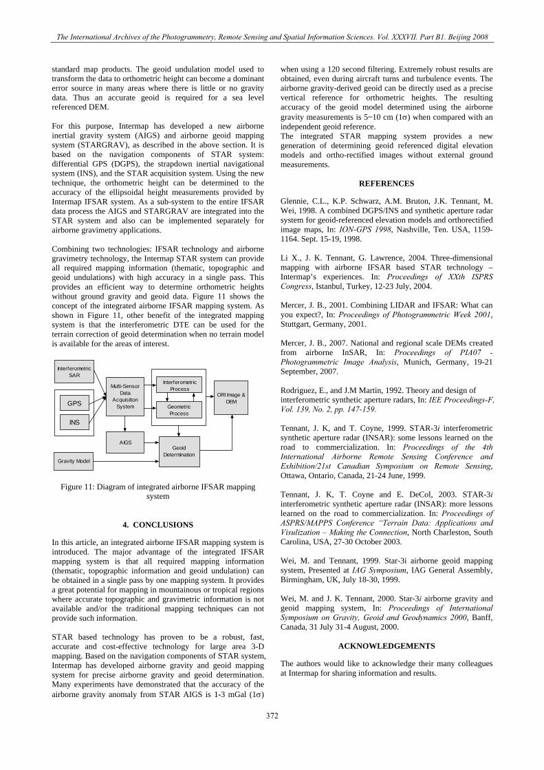
standard map products. The geoid undulation model used to transform the data to orthometric height can become a dominant error source in many areas where there is little or no gravity data. Thus an accurate geoid is required for a sea level referenced DEM. For this purpose, Intermap has developed a new airborne inertial gravity system (AIGS) and airborne geoid mapping system (STARGRAV), as described in the above section. It is based on the navigation components of STAR system: differential GPS (DGPS), the strapdown inertial navigational system (INS), and the STAR acquisition system. Using the new technique, the orthometric height can be determined to the accuracy of the ellipsoidal height measurements provided by Intermap IFSAR system. As a sub-system to the entire IFSAR data process the AIGS and STARGRAV are integrated into the STAR system and also can be implemented separately for airborne gravimetry applications. Combining two technologies: IFSAR technology and airborne gravimetry technology, the Intermap STAR system can provide all required mapping information (thematic, topographic and geoid undulations) with high accuracy in a single pass. This provides an efficient way to determine orthometric heights without ground gravity and geoid data. Figure 11 shows the concept of the integrated airborne IFSAR mapping system. As shown in Figure 11, other benefit of the integrated mapping system is that the interferometric DTE can be used for the terrain correction of geoid determination when no terrain model is available for the areas of interest.
GeoidDetermination
AIGS
Gravity Model
Multi-SensorData
AcquisitionSystem
InterferometricSAR
GPS
INS
ORI Image &DEM
InterferometricProcess
GeometricProcess
Figure 11: Diagram of integrated airborne IFSAR mapping system
4. CONCLUSIONS
In this article, an integrated airborne IFSAR mapping system is introduced. The major advantage of the integrated IFSAR mapping system is that all required mapping information (thematic, topographic information and geoid undulation) can be obtained in a single pass by one mapping system. It provides a great potential for mapping in mountainous or tropical regions where accurate topographic and gravimetric information is not available and/or the traditional mapping techniques can not provide such information. STAR based technology has proven to be a robust, fast, accurate and cost-effective technology for large area 3-D mapping. Based on the navigation components of STAR system, Intermap has developed airborne gravity and geoid mapping system for precise airborne gravity and geoid determination. Many experiments have demonstrated that the accuracy of the airborne gravity anomaly from STAR AIGS is 1-3 mGal (1σ)
when using a 120 second filtering. Extremely robust results are obtained, even during aircraft turns and turbulence events. The airborne gravity-derived geoid can be directly used as a precise vertical reference for orthometric heights. The resulting accuracy of the geoid model determined using the airborne gravity measurements is 5~10 cm (1σ) when compared with an independent geoid reference. The integrated STAR mapping system provides a new generation of determining geoid referenced digital elevation models and ortho-rectified images without external ground measurements.
REFERENCES
Glennie, C.L., K.P. Schwarz, A.M. Bruton, J.K. Tennant, M. Wei, 1998. A combined DGPS/INS and synthetic aperture radar system for geoid-referenced elevation models and orthorectified image maps, In: ION-GPS 1998, Nashville, Ten. USA, 1159-1164. Sept. 15-19, 1998. Li X., J. K. Tennant, G. Lawrence, 2004. Three-dimensional mapping with airborne IFSAR based STAR technology – Intermap’s experiences. In: Proceedings of XXth ISPRS Congress, Istanbul, Turkey, 12-23 July, 2004. Mercer, J. B., 2001. Combining LIDAR and IFSAR: What can you expect?, In: Proceedings of Photogrammetric Week 2001, Stuttgart, Germany, 2001. Mercer, J. B., 2007. National and regional scale DEMs created from airborne InSAR, In: Proceedings of PIA07 - Photogrammetric Image Analysis, Munich, Germany, 19-21 September, 2007. Rodriguez, E., and J.M Martin, 1992. Theory and design of interferometric synthetic aperture radars, In: IEE Proceedings-F, Vol. 139, No. 2, pp. 147-159. Tennant, J. K, and T. Coyne, 1999. STAR-3i interferometric synthetic aperture radar (INSAR): some lessons learned on the road to commercialization. In: Proceedings of the 4th International Airborne Remote Sensing Conference and Exhibition/21st Canadian Symposium on Remote Sensing, Ottawa, Ontario, Canada, 21-24 June, 1999. Tennant, J. K, T. Coyne and E. DeCol, 2003. STAR-3i interferometric synthetic aperture radar (INSAR): more lessons learned on the road to commercialization. In: Proceedings of ASPRS/MAPPS Conference “Terrain Data: Applications and Visulization – Making the Connection, North Charleston, South Carolina, USA, 27-30 October 2003. Wei, M. and Tennant, 1999. Star-3i airborne geoid mapping system, Presented at IAG Symposium, IAG General Assembly, Birmingham, UK, July 18-30, 1999. Wei, M. and J. K. Tennant, 2000. Star-3i airborne gravity and geoid mapping system, In: Proceedings of International Symposium on Gravity, Geoid and Geodynamics 2000, Banff, Canada, 31 July 31-4 August, 2000.
ACKNOWLEDGEMENTS
The authors would like to acknowledge their many colleagues at Intermap for sharing information and results.
372