Integral Asymmetric Isoporous Membrane Formation From ...
166
Integral Asymmetric Isoporous Membrane Formation From Novel Block Copolymers Dissertation Dissertation submitted in partial fulfillment of the requirements for the Degree of Doctor of Science (Dr. rer. nat.) To The University of Hamburg, Institute of Physical Chemistry, Department of Chemistry, MIN Faculty Submitted by Sarah Saleem Hamburg, 2020
Transcript of Integral Asymmetric Isoporous Membrane Formation From ...

Integral Asymmetric Isoporous Membrane
Formation From Novel Block Copolymers
Dissertation
Dissertation submitted in partial fulfillment of the requirements for the
Degree of Doctor of Science (Dr. rer. nat.)
To
The University of Hamburg,
Institute of Physical Chemistry, Department of Chemistry, MIN Faculty
Submitted by
Sarah Saleem
Hamburg, 2020

ii
Reviewer 1: Prof. Dr. Volker Abetz
Reviewer 2: Prof. Dr. Gerrit A. Luinstra
Date of Defense: 27.11.2020
Examiner 1: Prof. Dr. Volker Abetz
Examiner 2: Prof. Dr. Hans-Ulrich Moritz
Examiner 3: Priv. Doz. Dr. Christoph Wutz

iii
The work presented in this dissertation was conducted from June, 2015-October, 2019 at the
Institute of Polymer Research, Helmholtz-Zentrum Geesthacht (HZG) under the supervision
of Prof. Dr. Volker Abetz.

iv
List of Publications
1. Block Copolymer Membranes from Polystyrene-b-poly(solketal methacrylate) (PS-b-
PSMA) and Amphiphilic Polystyrene-b-poly(glyceryl methacrylate) (PS-b-PGMA). Sarah
Saleem, Sofia Rangou, Clarissa Abetz, Brigitte Lademann, Volkan Filiz, Volker Abetz,
Polymers 2017, 9(6), 216.
2. Isoporous Membranes from Novel Polystyrene-b-poly(4-vinylpyridine)-b-poly(solketal
methacrylate) (PS-b-P4VP-b-PSMA) Triblock Terpolymers and Their Post-Modification.
Sarah Saleem, Sofia Rangou, Clarissa Abetz, Volkan Filiz, Volker Abetz, Polymers 2020,
12(1), 41.

v
Table of Contents
List of Figures ix List of Schemes xiii
List of Tables xiii
List of Symbols xiv
List of Abbreviations xv
Chapter 1: Introduction .................................................................................. 1
1.1 Objective ....................................................................................................................................... 6
1.2 Strategy of work and layout of the thesis ..................................................................................... 6
Chapter 2: Theoretical background ................................................................ 8
2.1 Anionic polymerization .................................................................................................................. 8
2.1.1 Mechanism of anionic polymerization ....................................................................................... 9
2.1.2 Molar mass distribution in living polymerizations ................................................................... 14
2.2 Block copolymers ........................................................................................................................ 15
2.2.1 Self-assembly of block copolymers and phase separation behavior ....................................... 16
2.2.2 Block copolymers in solution.................................................................................................... 20
2.3 Types of membranes ................................................................................................................... 23
2.3.1 Phase separation membranes .................................................................................................. 24
2.3.2 Isoporous block copolymer membranes via SNIPS .................................................................. 25
Chapter 3: Experimental work ....................................................................... 31
3.1. Materials ..................................................................................................................................... 31
3.1.1 Cleaning of chemicals ............................................................................................................... 31
3.1.2 Anionic polymerization of block copolymers ........................................................................... 32
3.1.3 Synthesis of poly(solketal methacrylate) (PSMA) homopolymer ............................................ 32
3.1.4 Synthesis of poly(glycidyl methacrylate) (PGM) homopolymer ............................................... 33
3.1.5 Synthesis of polystyrene-block-poly(4-vinylpyridine) (PS-b-P4VP) diblock copolymer ........... 34
3.1.6 Synthesis of polystyrene-block-poly(solketal methacrylate) (PS-b-PSMA) diblock copolymer 35
3.2 Modification of PS-b-PSMA diblock copolymers ......................................................................... 37
3.2.1 Acidic hydrolysis of PS-b-PSMA ................................................................................................ 37

vi
3.2.2 Synthesis of polystyrene-block-poly(glycidyl methacrylate) (PS-b-PGM) diblock copolymer . 37
3.3 Synthesis of triblock terpolymers by anionic polymerization ..................................................... 39
3.3.1 Synthesis of polystyrene-block-poly(4-vinylpyridine)-block-poly(solketal methacrylate) (PS-b-
P4VP-b-PSMA) triblock terpolymer ................................................................................................... 39
3.3.2 Acidic hydrolysis of triblock terpolymers ................................................................................. 40
3.3.3 Synthesis of polystyrene-block-poly(4-vinylpyridine)-block-poly(glycidyl methacrylate) (PS-b-
P4VP-b-PGM) triblock terpolymer..................................................................................................... 41
3.4 Membrane formation .................................................................................................................. 43
3.4.1 Hand casting ............................................................................................................................. 43
3.4.2 Machine casting ....................................................................................................................... 43
3.4.3 Spin coating of polymer film .................................................................................................... 44
3.4.4 Post modification of triblock terpolymer membranes ............................................................. 44
3.4.5 Preparation of GO/PGO-PS-b-PGMA membranes ................................................................... 44
3.5 Characterization techniques ....................................................................................................... 45
3.5.1 Size exclusion chromatography (SEC) ...................................................................................... 45
3.5.2 Nuclear magnetic resonance spectroscopy (NMR) .................................................................. 46
3.5.3 Scanning electron microscopy (SEM) ....................................................................................... 47
3.5.4 Transmission electron microscopy (TEM) ................................................................................ 49
3.5.5 Atomic force microscopy (AFM) ............................................................................................... 50
3.5.6 Contact angle measurements .................................................................................................. 51
3.5.7 Water flux measurements ........................................................................................................ 52
3.5.8 Static protein adsorption.......................................................................................................... 53
3.5.9 Retention measurements ......................................................................................................... 54
3.5.10 X-ray photoelectron spectroscopy (XPS) ................................................................................ 55
Chapter 4: Results and discussion ................................................................. 56
Synthesis of polystyrene-b-poly(solketal methacrylate) (PS-b-PSMA) and formation of membranes
via SNIPS ............................................................................................................................................ 56
4.1. Brief introduction ....................................................................................................................... 56
4.1.1 Synthesis and characterization of poly(solketal methacrylate) (PSMA) .................................. 56
4.1.2 Synthesis and characterization of polystyrene-block-poly(4-vinylpyridine) (PS-b-P4VP) diblock
copolymer .......................................................................................................................................... 58
4.1.3 Synthesis and characterization of polystyrene-block-poly(solketal methacrylate) (PS-b-PSMA)
diblock copolymer ............................................................................................................................. 59
4.1.4 Bulk Morphology of the PS-b-PSMA diblock copolymers ........................................................ 63
4.1.5 Membrane fabrication via SNIPS .............................................................................................. 65
4.2. A comparative study of amphiphilic polystyrene-b-poly(glyceryl methacrylate) (PS-b-PGMA)
and hydrophobic polystyrene-b-poly(solketal methacrylate) (PS-b-PSMA) membranes ................. 70

vii
4.2.1 Brief Introduction ..................................................................................................................... 70
4.2.2 Acidic hydrolysis of PS-b-PSMA and formation of PS-b-PGMA diblock copolymer ................. 70
4.2.3 Protection of hydroxyl groups (-OH) of PGMA ......................................................................... 72
4.2.4 Benzoylation of polystyrene-block-poly(glyceryl methacrylate) (PS-b-PGMA) ........................ 72
4.2.5 Silylation of polystyrene-block-poly(glyceryl methacrylate) (PS-b-PGMA) .............................. 73
4.2.6 Analysis of bulk morphology of the PS-b-PGMA by TEM ......................................................... 75
4.2.7 Fabrication of PS-b-PGMA membranes via SNIPS .................................................................... 77
4.2.8 Addition of nano-fillers ............................................................................................................. 81
4.2.9 Addition of PDEA-GO to the PS-b-PGMA polymer solution ..................................................... 85
4.2.10 Membrane morphology and functional group characterization ........................................... 86
4.2.11 Comparison of static adsorption of proteins/antifouling behavior ....................................... 91
4.2.12 Comparison of dynamic contact angle measurements .......................................................... 93
4.2.13 Water flux measurements ...................................................................................................... 94
Chapter 5 ...................................................................................................... 97
Isoporous membranes from novel polystyrene-b-poly(4-vinylpyridine)-b-poly(solketal
methacrylate) (PS-b-P4VP-b-PSMA) triblock terpolymers and their post-modification ................... 97
5.1. Brief Introduction ....................................................................................................................... 97
5.1.1 Synthesis and characterization of polystyrene-block-poly(4-vinylpyridine)-block-poly(solketal
methacrylate) (PS-b-P4VP-b-PSMA) triblock terpolymer .................................................................. 98
5.1.2 Bulk morphology of the triblock terpolymers ........................................................................ 101
5.1.3 Preparation of the membrane by SNIPS ................................................................................ 103
5.1.4 Post-modification of PS71-b-P4VP17-b-PSMA1291 triblock terpolymer ..................................... 107
5.1.5 Membrane fabrication after post-modification of triblock terpolymer ................................ 109
5.1.6 Post-modification of PS71-b-P4VP26-b-PSMA3145 membranes. ................................................ 110
5.2 Comparison of the performance of membranes ...................................................................... 110
5.2.1 Comparison of contact angle measurements ........................................................................ 111
5.2.2 Water permeation and pH responsive behavior .................................................................... 112
5.2.3 BSA retention measurements ................................................................................................ 114
5.2.4 Static adsorption of hemoglobin ............................................................................................ 115
Chapter 6: Summary and outlook ................................................................ 118
6.1. Summary and outlook .............................................................................................................. 118
6.2. Zusammenfassung und Ausblick .............................................................................................. 120
Chapter 7: References ................................................................................. 122
Chapter 8: Appendix ................................................................................... 137
8.1.Toxicity of chemicals ................................................................................................................. 137
8.2. Calculation of the solubility parameters according to HOY method........................................ 139

viii
8.3. Synthesis and characterization of poly(glycidyl methacrylate) (PGM) homopolymer ............. 141
8.3.1 Synthesis and characterization of polystyrene-block-poly(glycidyl methacrylate) (PS-b-PGM)
diblock copolymer ........................................................................................................................... 142
8.3.2 Synthesis and characterization of polystyrene-block-poly(4-vinylpyridine)-block-poly(glycidyl
methacrylate) (PS-b-P4VP-b-PGM) triblock terpolymer ................................................................. 144
Acknowledgements 147
Curriculum Vitae 148
Declaration of Oath 149

ix
List of Figures
Figure 1. 1. Membrane separation processes for water purification and desalination based on
the size of solute. Reprinted with permission from ref [7] ......................................................... 2
Figure 1. 2. Schematic illustration of a wide range of target applications where block
copolymer membranes with well-controlled functional pore wall chemistries could be
utilized. Reprinted with permission from ref [19] ...................................................................... 3
Figure 2. 1. Molecular weight conversion curves for various kinds of polymerization methods
(A) living polymerization (B) free radical polymerization and (C) condensation
polymerization. Reprinted with permission from ref [55] ......................................................... 9
Figure 2. 2. Typical structures of block copolymers containing A, B and C block ................ 15
Figure 2. 3. Theoretical phase diagram of a linear diblock copolymer by self-consistent mean
field theory. Body-centered cubic (BCC), hexagonally packed cylinder (HEX), minimal
surfaces (gyroid (GYR) and alternating simple lamellar phase (LAM). Reprinted with
permission from ref [84]. ......................................................................................................... 18
Figure 2. 4. Ternary phase diagram of polystyrene-block-polybutadiene-block-poly(methyl
methacrylate) (SBM) triblock terpolymers. Reprinted with permission from ref [102]. ......... 20
Figure 2. 5. Basic morphologies of (AB) block copolymer aggregates in solution. Reprinted
with permission from ref [106, 107] ........................................................................................ 21
Figure 2. 6. Schematic representation of different types of micelles formed by ABC triblock
terpolymers. Core-shell-corona micelles with a compartmentalized core (a), micelles with a
mixed corona (no chain segregation) (b), core-shell-corona micelles with a compartmentalized
corona (radial chain segregation) (c), Janus micelles with an asymmetric corona (lateral chain
segregation) (d), and vesicles (e). Reprinted with permission from ref [99]. .......................... 22
Figure 2. 7. Schematic illustration of symmetric and asymmetric membrane structure.
Reprinted with permission from ref [112] ................................................................................ 24
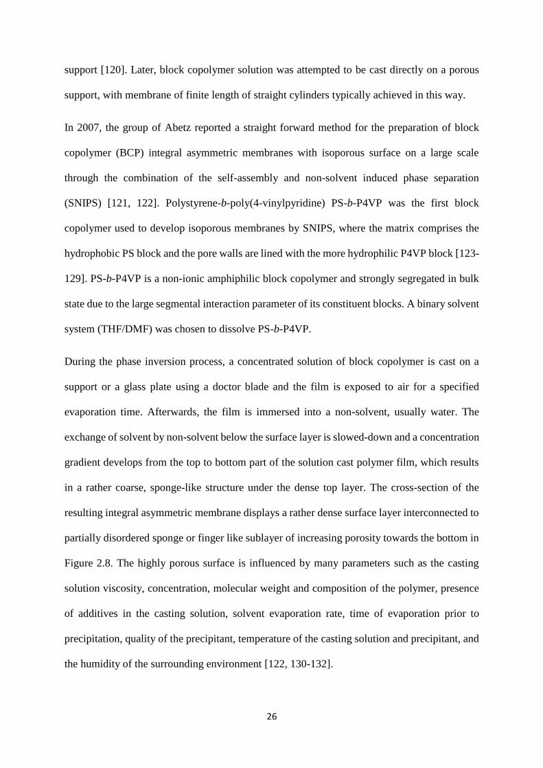
Figure 2. 8. Scanning electron microscopy (SEM) images of the surface and cross-section of
the integral asymmetric isoporous PS-b-P4VP diblock copolymer film following SNIPS. The
scale bar correspond to 500 nm. The evaporation time before immersion into non-solvent bath
is 10 s. Reprinted with permission from ref [121] ................................................................... 27
Figure 2. 9. Schematic illustration of the structure formation of isoporous membrane from the
solution: i) Disordered or weakly segregated diblock copolymer in mixed selective solvents (
polystyrene rich domains, poly(4-vinylpyridine) rich domains ii) microphase
separation with polystyrene rich matrix after film casting; iii) solidification of the matrix due
to solvent evaporation; iv) open pores in the poly(4-vinylpyridine) rich domains after non-
solvent induced phase separation; v) Porous structure of dried membrane. This figure is
reprinted from reference.[122] ................................................................................................. 27
Figure 2. 10. Representation of possible hydrogen bonding between PS-b-P4VP as hydrogen
bond acceptor and carbohydrate molecule. Reprinted with permission from ref [139]. .......... 29

x
Figure 3. 1. Schematic representation (a) and (b) of the in-house built casting machine used
for fabrication of membrane via SNIPS. Reprinted with permission from ref [123]. .............. 44
Figure 3. 2. Illustration of separation principle of size exclusion chromatography.[145] ...... 46
Figure 3. 3. Representative image of key components of Scanning Electron Microscope
(SEM).[148] ............................................................................................................................. 48
Figure 3. 4. Schematic illustration of the primary electron interaction with sample and
generation of secondary electrons, back scattered electrons and X-ray radiation.[149] .......... 48
Figure 3. 5. Main components of Transmission Electron Microscopy.[150] .......................... 49
Figure 3. 6. Schematic illustration of contact angle ................................................................ 51
Figure 3. 7. Classification of surfaces based on contact angle with water .............................. 52
Figure 3. 8. Test cell EMD MilliporeTM XFUF04701 ............................................................. 54
Figure 4.1.1. 1H-NMR spectra of PSMA homopolymer in CDCl3 ......................................... 57
Figure 4.1.2. 1H-NMR spectra of PS85-b-P4VP15166 in CDCl3 ................................................ 58
Figure 4.1.3. 1H-NMR spectrum of PS81-b-PSMA19170 in CDCl3 ........................................... 60
Figure 4.1.4. SEC traces of PS homopolymer and PS81-b-PSMA19170 diblock copolymer
(measurement in THF at 30 °C using PS standards) ................................................................ 61
Figure 4.1.5. TEM image of an ultrathin section of PS81-b-PSMA19170, film cast from 5 wt%
polymer solution in THF, the diameter of the brighter spheres is approximately 25-30 nm ... 64
Figure 4.1.6. SEM images of the top surface of cast membranes from 24 wt% PS76-b-
PSMA24
200 from (left) THF/DMF 50/50 wt%, (right) THF/DMF 40/60 wt%. The time of
evaporation before the immersion into the precipitant was 10 s. ............................................. 66
Figure 4.1.7. SEM topography images of the surface of the generated membrane from 25
wt% PS76-b-PSMA24200 in THF/DMF 30/70 wt% with evaporation time 10 s (left) and 20 s
(right) ........................................................................................................................................ 67
Figure 4.1.8. SEM images of surfaces of the membranes made from 24 wt% PS81-b-
PSMA19170 in THF/DMF 50/50 wt%. Evaporation time before immersion: (a) 5 s, (b) 10 s, (c)
20 s, (d) 25 s. ............................................................................................................................ 68
Figure 4.1. 9. SEM images of the cross-section of the membrane prepared from 24 wt% PS81-
b-PSMA19170 in THF/DMF 50/50 wt% at (a) 5 s, (b) 25 s time of evaporation ....................... 69
Figure 4.2.1. 1H-NMR spectrum of PS-b-PGMA after the removal of 1, 3-dioxolane ring of
PSMA block ............................................................................................................................. 71
Figure 4.2.2. Structure of benzoylated PS-b-PGMA diblock copolymer ............................... 73
Figure 4.2.3. Silylation of PS-b-PGMA diblock copolymer ................................................... 74
Figure 4.2.4. TEM image of an ultrathin section of PS81-b-PSMA19170, film cast from 5 wt%
diblock copolymer solution in DMF, the diameter of the brighter spheres is approximately 30-
35 nm ........................................................................................................................................ 76
Figure 4.2.5. TEM image of an ultrathin section of PS82-b-PSMA18126, film cast from diblock
copolymer in THF and DMF solution, stained with RuO4 (20min) ......................................... 77

xi
Figure 4.2.6. SEM topography images of membranes prepared from (a) 23 wt% PS76-b-
PSMA24135 and (b) 23 wt% PS81-b-PGMA19
128 in THF/DMF 50/50 wt%. The corresponding
cross-section views for each case are shown in (c) and (d) images, respectively. The time of
evaporation was 10s. ................................................................................................................ 78
Figure 4.2.7. SEM images of surface of the membranes prepared from 22 wt % PS81-b-
PGMA19128 in THF/DMF/DOX (1:1:1); time of evaporation (a) 10 s (b) 20 s. ....................... 80
Figure 4.2.8. SEM images of surface of the membranes prepared from 23 wt% (left) PS82-b-
PGMA18126 (right) PS79-b-PGMA21
120 in THF/DMF/DOX (2:1:1); time of evaporation 20 s. 81
Figure 4.2.9. Structure of graphene oxide layer.[171] ............................................................ 82
Figure 4.2.10. SEM images of surface of the membranes prepared from 23 wt% PS82-b-
PGMA18126 (a) pristine membrane, time of evaporation 20 s. (b) 0.5 (c) 1 wt% GO nanosheets
in THF/DMF/DOX (2:1:1); time of evaporation 10 s. ............................................................. 83
Figure 4.2.11. Surface SEM images of the membranes prepared from 23 wt% PS82-b-
PGMA18126 1 wt% GO nanosheets in THF/DMF/DOX (2:1:1); time of evaporation 10 s. ..... 84
Figure 4.2.12. The cross-sectional SEM images of pristine (a) 23 wt% PS82-b-PGMA18126 (b)
1 wt% GO in PS82-b-PGMA18126 in THF/DMF/DOX (2:1:1). The evaporation time after
addition of GO was shifted to 10 s. .......................................................................................... 85
Figure 4.2.13. SEM images of surface and cross-section of the membranes prepared from 23
wt% PS82-b-PGMA18126 in THF/DMF/DOX (2:1:1); time of evaporation 20 s. ..................... 87
Figure 4.2.14. Scanning electron micrograph images of cross section and surface (from left to
right) with 1.5 % (w/w) PDEA-GO in THF/DMF/DOX (2:1:1). The evaporation time after
addition of PDEA-GO nanosheets was shifted to 10 s. ............................................................ 88
Figure 4.2.15. XPS analysis of PS-b-PGMA diblock copolymer membrane and hybrid
membranes of PS-b-PGMA/PDEA-GO nanosheets ................................................................ 89
Figure 4.2.16. Atomic force micrograph of the surface and three dimensional images of
membranes (a) PS-b-PGMA (b) 1.5 wt% PS-b-PGMA/PDEA-GO nanosheets ..................... 89
Figure 4.2.17. SEM topography and cross-section images of membranes prepared from (left)
23 wt% PS82-b-PGMA18126 in THF/DMF/DOX (2:1:1) and (right) 28 wt% PS81-P4VP19
123 in
THF/DMF 50/50 wt%. The corresponding cross-section views for each case are shown under
the surface images (left) and (right), respectively. The time of evaporation was 10 s (left) and
5 s (right) .................................................................................................................................. 92
Figure 4.2.18. Adsorbed amount of foulants bovine serum albumin (BSA), gamma globulin
(ϒ-Glob), hemoglobin (Hem) at pH 7.4 for PS82-b-PGMA18126 and PS81-b-P4VP19
123
membranes ............................................................................................................................... 93
Figure 4.2.19. Graphical representation of the dynamic contact angle measurement of water
droplets (5 µL) onto membrane surfaces developed from block copolymers PS76-b-PSMA24135
and PS81-b-PGMA19128 (previously shown in Figure 4.2.6 a, b) .............................................. 94
Figure 4.2.20. Time dependent water flux measurements of PS81-b-PGMA19128 membrane . 95
Figure 5.1.1. 1H-NMR spectra of PS71-b-P4VP26-b-PSMA3145 in CDCl3 ............................... 98
Figure 5.1.2. SEC chromatogram of PS homopolymer, PS-b-P4VP and PS72-b-P4VP17-b-
PSMA1191 triblock terpolymer (measurement in THF at 30 °C using PS standards) ............... 99

xii
Figure 5.1.3. TEM micrographs of PS-b-P4VP-b-PSMA triblock terpolymer cast from
chloroform (a) PS71-b-P4VP17-b-PSMA1291 stained with RuO4 (b), with RuO4 and I2 ......... 102
Figure 5.1. 4. (a) TEM image of PS71-b-P4VP26-b-PSMA3145 stained with I2 (b) AFM height
image (in tapping mode) of the film surface of the asymmetric PS71-b-P4VP26-b-PSMA3145
triblock terpolymer ................................................................................................................. 102
Figure 5.1.5. SEM images of PS71-b-P4VP26-b-PSMA3145 membrane surfaces prepared from
different solutions: 22 wt% copolymer at 10 sec evaporation time in (a) 60/40 THF/DMF; (b)
50/50 THF/DMF; (c) 70/30 THF/DMF ................................................................................. 103
Figure 5.1.6. SEM images of the PS71-b-P4VP26-b-PSMA3145 membranes cast from a 22 wt%
copolymer solution in (a) THF/DMF/DOX 1/1/1 (b) THF/DMF/DOX 40/30/30. The
evaporation time before immersion into the precipitant was 10 seconds. ............................. 104
Figure 5.1.7. SEM images of (a) top view and (b) cross-section of PS71-b-P4VP26-b-
PSMA3145 membranes cast from 22 wt% solution in a THF/DMF/acetone: 50/30/20 wt%.
Evaporation time was 10 seconds before immersion in water ............................................... 105
Figure 5.1.8. Surface SEM images of PS71-b-P4VP26-b-PSMA3145 membranes cast from
solutions THF/DMF/Acetone: 50/30/20 wt%. (a) 20 seconds (b) 30 seconds evaporation time
before immersion into non-solvent bath. ................................................................................ 106
Figure 5.1.9. Surface SEM images of PS71-b-P4VP26-b-PSMA3145 membranes cast from 21
wt%, 23 wt%, and 24 wt% terpolymer solutions in THF/DMF/Acetone: 50/30/20 wt%. The
evaporation time before immersion into the precipitant was 10 s. ......................................... 107
Figure 5.1.10. 1H-NMR spectrum of the linear triblock terpolymer PS71-b-P4VP17-b-
PGMA1291 in DMF-d7 ............................................................................................................ 108
Figure 5.1.11. SEM images of (a) PS71-b-P4VP17-b-PSMA1291 membrane (b) PS71-b-P4VP17-
b-PGMA1291 membrane obtained after acidic hydrolysis. The evaporation time before
immersion into water bath was 10 s. ...................................................................................... 110
Figure 5.2.1. Dynamic contact angle measurements of water droplets (2µL each) onto the
PS71-b-P4VP26-b-PSMA3145 (black squares) and PS71-b-P4VP26-b-PGMA3
145 (red circles)
membranes ............................................................................................................................. 111
Figure 5.2.2. SEM images of pristine PS71-b-P4VP26-b-PSMA3145 membrane before acidic
hydrolysis and (b) PS71-b-P4VP26-b-PGMA3145 membrane................................................... 112
Figure 5.2.3. Water permeability of PS71-b-P4VP26-b-PGMA3145 membrane measured at
various pH, at pH ˃ 4 high water permeability was observed, due to deswelling of the
deprotonated P4VP blocks at larger pH, leading to their collapse on the pore walls ............ 113
Figure 5.2.4. Protein adsorption of hemoglobin of PS74-b-P4VP26162, PS71-b-P4VP26-b-
PSMA3145and PS71-b-P4VP26-b-PGMA3
145 membranes at pH 7.4 ........................................ 116
Figure 8. 1. 1H-NMR spectra of PGMA homopolymer in CDCl3 ........................................ 142
Figure 8. 2. 1H-NMR spectrum of PS79.5-b-PGM20.5112 in CDCl3 ......................................... 143
Figure 8. 3. SEC chromatogram of PS homopolymer and PS79.5-b-PGM20.5112 diblock
copolymer ............................................................................................................................... 144
Figure 8. 4. 1H-NMR spectra of PS-b-P4VP-b-PGM in CDCl3 ............................................ 145

xiii
List of Schemes
Scheme 2. 1. Attachment of anion to monomer and delocalization of charge .......................... 8
Scheme 2. 2. General way to initiate styrene with (a) mono and (b) di-functional initiators .. 11
Scheme 2. 3. Side reactions in the polymerization of methyl methacrylate, (a) initiator attack
on the monomer ester group (b) backbiting reaction of enolate anion ..................................... 12
Scheme 2. 4. Ion pairs in a polar solvent for different concentrations.[61-63] ....................... 13
Scheme 3. 1. Synthesis of PSMA homopolymer ..................................................................... 33
Scheme 3. 2. Synthesis of PGM homopolymer ....................................................................... 34
Scheme 3. 3. Synthesis of PS-b-P4VP ..................................................................................... 35
Scheme 3. 4. Synthetic route leading to PS-b-PSMA by sequential anionic polymerization of
styrene and solketal methacrylate ............................................................................................ 36
Scheme 3. 5. Acidic hydrolysis of PS-b-PSMA ...................................................................... 37
Scheme 3. 6. Synthetic route leading to PS-b-PGM by sequential anionic polymerization of
styrene and glycidyl methacrylate (GM) .................................................................................. 38
Scheme 3. 7. General reactions for the synthesis of PS-b-P4VP-b-PSMA triblock terpolymer
via sequential anionic polymerization. ..................................................................................... 40
Scheme 3. 8. Deprotection reaction of the ketal-PSMA moiety .............................................. 41
Scheme 3. 9. General reactions for the synthesis of linear triblock terpolymer PS-b-P4VP-b-
PGM by following anionic polymerization technique. ............................................................ 42
List of Tables
Table 4. 1. Molecular weight and dispersity index of the PSMA homopolymer .................... 57
Table 4. 2. Molecular weight, weight percentage of P4VP and dispersity index of PS-b-P4VP
.................................................................................................................................................. 59
Table 4. 3. Characterization data of PS-b-PSMA diblock copolymers ................................... 61
Table 4. 4. Hansen solubility parameters (δ) of homopolymers, solvents and non-solvents
[157] ......................................................................................................................................... 63
Table 4. 5. Characterization data of PS-b-PGMA diblock copolymers .................................. 75
Table 4. 6. Roughness parameters for membranes PS-b-PGMA and PS-b-PGMA/PDEA-GO
nanosheets ................................................................................................................................ 91
Table 5. 1. Composition and molecular weights of PS-b-P4VP-b-PSMA triblock terpolymer
................................................................................................................................................ 100
Table 5. 2. Retention results from experiments in a 1 mg/1 mL BSA solution in (PBS buffer
pH = 7.4). ............................................................................................................................... 114

xiv
Table 8. 1. Molecular weight and dispersity index of the PGM homopolymer .................... 142
Table 8. 2. Characterization data of PS-b-PGM block copolymers ...................................... 143
Table 8. 3. Characterization data of PS-b-P4VP-b-PGM triblock terpolymer ...................... 146
List of Symbols
α Molecular aggregation number
b Grafting distance
δD Dispersion solubility parameter
δP Polar solubility parameter,
δH Hydrogen Bonding solubility parameter
m0 Mass of the protein before the adsorption
m1 Mass of the protein after the adsorption
𝛥t Time between two mass measurements
𝛥𝑝 Trans-membrane pressure
λ Wavelength
A Active surface area of the membrane
AB Diblock copolymer with A and B block
ABC Triblock terpolymer with A, B and C block
Ð Dispersity index
Ft Molar attraction function
Fp Polar component
N Degree of polymerization
Ra Mean surface roughness
Rq Root mean square
V Molar volume

xv
List of Abbreviations
AFM Atomic Force Microscopy
BCP Block copolymer
BSA Bovine Serum Albumin
C or C’ Cylinder
CaH2 Calcium Hydride
CDCl3 Deuterated chloroform
DMAc Dimethylacetamide
DMF N,N-dimethylformamide
DOX Dioxane
DPE 1,1-Diphenylethylene
EtAlCl2 Ethylaluminium dichloride
G or G’ Gyroid
GO Graphene oxide
ϒ-Glob Gamma-Globulin
1H-NMR Proton nuclear magnetic resonance spectroscopy
HCl Hydrochloric acid
Hem Hemoglobin
IPGMA Iso-propylglyceryl methacrylate
IEP Isoelectric point
L Lamellar
LiCl Lithium chloride
MeOH Methanol
MgBu2 Dibutylmagnesium
Mn Number average molecular wight

xvi
Mw Weight average molecular weight
MWCO Molecular weight cut-off
MWD Molecular weight distribution
NaOH Sodium hydroxide
NH Amine
NIPS Non-solvent induced phase separation
PDEAEMA Poly(2-(diethylamino)ethyl methacrylate
PGM Poly(glycidyl methacrylate)
PGMA Poly(glyceryl methacrylate)
PS Polystyrene
PSF Polysulfone
PSMA Poly(solketal methacrylate)
PS-b-P4VP Polystyrene-block-poly(4-vinylpyridine)
PS-b-PGM Polystyrene-block-poly(glycidyl methacrylate)
PS-b-PGMA Polystyrene-block-poly(glyceryl methacrylate)
PS-b-PSMA Polystyrene-block-poly(solketal methacrylate)
PS-b-P4VP-b-PSMA Polystyrene-block-poly(4-vinylpyridine)-block-
poly(solketal methacrylate)
PS-b-P4VP-b-PGMA Polystyrene-block-poly(4-vinylpyridine)-block-
poly(glyceryl methacrylate)
PS-b-PQ4VP-b-PGMA Polystyrene-block-quarternized poly(4-vinylpyridine)-
block- poly(glyceryl methacrylate
PS-b-P4VP-b-PGM Polystyrene-block-poly(4-vinylpyridine)-block-
poly(glycidyl methacrylate)
PVDF Poly(vinylidene fluoride)
RuO4 Rutheniumtetraoxide

xvii
S or S’ Spherical
sec-BuLi sec-butyl lithium
SEC Size-exclusion Chromatography
SEM Scanning Electron Microscopy
SH Thiol
SNIPS Self-assembly and non-solvent induced phase separation
SSL Strong segregation limit
TEM Transmission Electron Microscopy
THF Tetrahydrofuran
TMS Tetramethylsilane
4VP 4-vinyl pyridine
WSL Weak segregation limit
XPS X-ray Photoelectron Spectroscopy

1
Chapter 1: Introduction
Water is one of the most precious resources for life. Although there are many sources of water
on the planet but most of them are dispensable or have inadequate quality for human
consumption or chemical and pharmaceutical industry/agricultural purposes. Increasing
demands of industrialization, urbanization and climate change are major factors on the way to
access clean water. It becomes one of the biggest challenges of our time to access fresh water.
The world population is rapidly increasing overall and over one third of world’s population
lives in the developing countries, where the economic impact of poor water and sanitation
ability is devastating. The contamination of drinking water resources by flowing streams of
wastewater (e.g., industrial, municipal and agricultural wastewater) is a worldwide problem. To
address this challenge, there is an important need for the development of energetically efficient,
low cost and sustainable methods for decontamination of water [1-3].
Membrane-based technologies are currently used in various processes for gas separation,
bioprocessing, biomedical applications, chemical productions, and considered inherently more
energy efficient than thermal separation approaches [4]. In the field of water, reverse osmosis
(RO) membranes of satisfactory flux and salt rejection are well-established for seawater
desalination [5]. With the development of modern science and technologies, various materials
have been applied for the fabrication of polymeric hemodialysis membranes [6].
Size based separation of particles through membrane technology can be divided according to
the size of solutes in four types: microfiltration (MF) (0.1-10 µm), ultrafiltration (UF) (2-100
nm), nanofiltration (NF) (1-10 nm) and reverse osmosis (RO) (less than 1 nm), a process as
shown in Figure 1.1.

2
Figure 1. 1. Membrane separation processes for water purification and desalination based on
the size of solute. Reprinted with permission from ref [7].
MF and UF membranes separation are based on the size of the solute, In specie solutes larger
than the membrane pore size are rejected/retained on the membrane surface [8] [9]. RO
membranes are dense (non-porous) membranes that can remove salts from water through
solution-diffusion mechanism [10]. NF membranes are using a combination of diffusive,
convective and electrostatic models for separation of multivalent ions [11, 12]. MF and UF
membranes are useful for removing large colloids, microbes and viruses from the feed. In the
field of biomedicines, membrane technology plays a vital role in the hemodialysis (purifying
blood) to treat chronic kidney failure which saves the lives of more than 2.5 million patients
worldwide [13]. For the targeted separations, well-defined nanostructure and surface properties
of block copolymer membranes can be modified chemically to the specific demands, considered
an emerging area of study [14, 15]. Self-assembled membranes with specific functional moieties
have been achieved in several ways, including the incorporation of the desired chemistry into
the precursor block copolymer material during synthesis with the purpose of the fabrication of
porous membranes where the pore wall constitutes from the respective functional groups.
Polystyrene-block-poly(4-vinylpyridine) (PS-b-P4VP) block copolymers represent this type of

3
system due to the presence of the functional P4VP block which can, for example, form
complexes with metal salts. Apart from size-selective membranes decorated with specific
functionalities, advanced technologies also focus on charge-selective membranes that exhibit
preferential permeability for electrolytes and retain small nonionic molecules [16-18].
Figure 1. 2. Schematic illustration of a wide range of target applications where block copolymer
membranes with well-controlled functional pore wall chemistries could be utilized. Reprinted
with permission from ref [19].
In the field of water purification and protein separation, block copolymer filtration membranes
attracted immense attention [20-23]. To date, majority of the membranes have been modified
using chemistries aimed at reducing the deleterious effects of fouling. Foulants like proteins,
emulsified oils, microorganisms, and a fraction of natural organic matters can be separated by
many polymeric membranes, as a higher affinity for adhesion is observed for hydrophobic than
hydrophilic membranes. Poor antifouling properties are mainly caused by the hydrophobic
behavior of membranes surfaces. Therefore, many surface modifications focus on
hydrophilizing a hydrophobic membrane surface, as it is hypothesized that surfaces with these
chemical properties are prone to tightly bind a thin layer of water, providing a steric or energetic
barrier to adhesion [24-26]. Hydrophilic surfaces which do not contain hydrogen bond donor
but only acceptor functions or are neutral, tend to be best at resisting protein adhesion [4, 27-
31].

4
Block copolymer membranes fabrication with a focus on reducing the fouling propensity
involves different approaches from simple coating, to radiation and photochemical grafting of
hydrophilic polymers [32, 33] , or using directly synthesized appropriate block copolymers for
the membrane formation. Block copolymer membranes may be directly coated with another
material that is simply adsorbed to the membrane surface through (e.g., van der Waals or
electrostatic interactions) [34, 35] or covalently coupled to the membrane polymer to afford
enhanced stability [36]. One of the earliest published works to improve the biocompatibility of
block copolymer membranes was performed by Matsuda and Ito. They coated a hydrophobic
polyacrylonitrile hemodialyser membrane with block copolymers of poly(methyl methacrylate)
and a hydrophilic segment of either poly(methoxy polyethylene glycol methacrylate) or
poly(dimethyl acrylamide) [37].
Another approach was to tailor the surface chemistry of membranes by the addition of surface
modifying macromolecules/additives in the membrane casting solution. In related studies,
hydrophilic surface modifying macromolecules of polyurethanes end-capped with
poly(ethylene glycol) (PEG) were incorporated in the poly(ether sulfone) (PES) casting
solution. The resulting membranes showed high water flux and lower contact angle
measurements than the PES membranes [38]. Blending of block copolymers was shown to be
a facile way to tune the pore size of isoporous membranes [39] and to alter in parallel the
transport properties of the membranes. Ma and co-workers reported high protein adsorption
resistant ultrafiltration membranes by blending an amphiphilic copolymer PS-b-PEG with PES
membranes [40, 41]. More specific it was reported that during the process of the pore formation,
the hydrophilic block was prone to come to the surface of the membrane, decreasing the contact
angle.
Rather than incorporating a material into the casting solution or coating the membrane surface
to impart desirable properties, our aim was to design new functional block copolymers with

5
improved hydrophilic and thus also antifouling properties, and furthermore to find ways to
design the chemical properties of the pores in the new membrane. The most-studied hydrophilic
segments in the field of amphiphilic block copolymers are poly(ethylene oxide) [42],
poly(methacrylic acid) [43], and poly(2-hydroxy ethyl methacrylate) [44]. In our group for the
first time, a series of triblock terpolymers of PS-b-P2VP-b-PEO was synthesized and integral
asymmetric membranes with pH responsive pores were developed via SNIPS. The presence of
a water-soluble short poly(ethylene oxide) (PEO) end block offers possibilities for post-
modification [45].
Poly(isopropylidene glycerol methacrylate)—commonly known as poly(solketal methacrylate)
acts as a precursor polymer of poly(glyceryl methacrylate) (PGMA) which was reported for the
first time in 1990. Mori et al. reported the sequential anionic polymerization of styrene and
solketal methacrylate (polystyrene-b-poly(solketal methacrylate)), (PS-b-PSMA) followed by
the deprotection of acetonide groups to obtain PS-b-PGMA [46]. Poly(glyceryl methacrylate)
(PGMA) is a potential alternative for the less hydrophilic 2-hydroxyethyl methacrylate
(HEMA) due to the presence of one extra hydroxyl group (–OH) per repeating unit of the
polymer in products such as contact lenses, drug delivery, and hydrogels. Zhang et al. used a
combination of living anionic polymerization of allyl methacrylate (PAMA) and afterwards
functionalization of the allyl side groups with osmium tetroxide to achieve PGMA [47]. It has
also been reported as a material for ultrafiltration barriers mimicking the natural membranes in
kidneys [48]. The first attempt to prepare a membrane from this diblock copolymer was reported
by Hahn et al. who used PS-b-PSMA for air brush spraying on a PVDF support membrane [49].
Poly(isopropylidene glycerol methacrylate) is one of those polymers not yet studied widely in
the context of block copolymer membranes produced via the SNIPS process.

6
1.1 Objective
Based on this background the main objective of the present work is to prepare integral
asymmetric isoporous membrane via self-assembly and non-solvent induced phase separation
process. In this regard, synthesis of a series of novel diblock and triblock terpolymers performs
via sequential anionic polymerization of AB and ACB architecture. In the second step of this
investigation, different parameters concentration of the polymer, (mixed) solvent interactions
to different blocks, evaporation time, composition of the solvents are optimized to obtain
integral asymmetric isoporous membranes from diblock and triblock terpolymers by following
self-assembly and non-solvent induced phase separation (SNIPS) process. In the third step,
post-modification of membranes is performed in a non-solvent while the isoporous structure of
the membrane is preserved. Finally, a comparative analysis is conducted to compare the
performance of membranes before and after modification.
1.2 Strategy of work and layout of the thesis
The present doctoral work is organized as follows:
-In Chapter 2, theoretical background briefly presenting the mechanism of anionic
polymerization, the principles of non-solvent induced phase separation (NIPS), the role of self-
assembly, the phase separation of block copolymers and the formation of isoporous membrane
via SNIPS.
-In Chapter 3, the materials used in this work are presented and the experimental procedures
employed for the synthesis and post-modification of polymers are explained. Later, it deals with
the characterization techniques used in this study.
-Chapter 4 is subdivided in two topics as follows: (i) Chapter 4.1 portrays the results of (PS-
b-PSMA) diblock copolymers synthesized by anionic polymerization and description of
optimization of different parameters to obtain isoporous membranes. (ii) Chapter 4.2 deals

7
with the modification of (PS-b-PSMA) diblock copolymers whereas a comparative analysis of
(PS-b-PGMA) with (PS-b-PSMA) and (PS-b-P4VP) diblock copolymer membranes is
demonstrated in the second part of this chapter.
-Chapter 5 is divided in two sub chapters as follows (i) Chapter 5.1 describes the results
obtained from synthesis of linear triblock terpolymers by anionic polymerization and the
optimization of the triblock terpolymers solutions to obtain integral asymmetric membranes
with an isoporous surface by SNIPS. (ii) Chapter 5.2 deals with the performance of isoporous
membranes obtained from triblock terpolymers and additionally a comparative study before and
after the modification of membranes was performed.
-Chapter 6 depicts the summary and outlook of this work
-Chapter 7 and 8 are dedicated to references and appendix

8
Chapter 2: Theoretical background
2.1 Anionic polymerization
Anionic living polymerization is an established versatile approach for the synthesis of block
copolymers that proceeds in the absence of termination and chain transfer [50, 51]. In 1956,
Szwarc and coworkers demonstrated for the first time living anionic polymerization of
polydienyl-lithium and polystyryl sodium chains in hydrocarbon media [52]. The term ‘living’
defines systems where no irreversible chain transfers and terminations occur during the course
of polymerization [53]. This implies that polymerization proceeds until all the monomer is
consumed and further addition of monomer would continue the growth of chain, thus increasing
the degree of polymerization. Polymers with predetermined molar mass and very narrow
molecular weight distribution could be obtained if the rate of initiation (Ri) is much faster than
that of propagation (Rp). Only in the living anionic polymerization, molecular weight is directly
proportional to monomer conversion (see Figure 2.1). In anionic polymerization, monomers
that are capable of making stable carbanion, can be polymerized anionically, Scheme (2.1) [54].
Scheme 2. 1. Attachment of anion to monomer and delocalization of charge
The kinetics of rate of initiation in polar and non-polar solvents are highly dependent on the
reaction conditions. ki is the rate constant of the initiation step and kp is the rate constant for the
propagation step.
The chains will stay active unless there is a deliberate termination. Inert atmosphere or high
vacuum conditions are maintained throughout the polymerization to avoid rapid termination of

9
active living chains due to reaction with oxygen, moisture and carbon dioxide (CO2). Different
reaction products are made by such termination. The stability of propagating centers,
termination, transfer and other chain breaking reactions can be suppressed by reducing the
temperature during polymerization.
Figure 2. 1. Molecular weight conversion curves for various kinds of polymerization methods
(A) living polymerization (B) free radical polymerization and (C) condensation polymerization.
Reprinted with permission from ref [55].
Anionic polymerization is widely exploited in industry to create BCPs on a massive scale as
compared to radical polymerization, due to its remarkable control over the molecular weight,
composition and functionality [56].
2.1.1 Mechanism of anionic polymerization
According to M. Szwarc ‘polymeric molecules are born in an initiation process, they grow by
a propagation process, and finally they ‘die’ in a termination process’

10
The mechanism of anionic polymerization divided into three principal steps
(a) Initiation
(b) Propagation
(c) Termination
(a) Initiation
In anionic polymerization, the rate of initiation has to be faster than the rate of propagation if a
narrow molecular weight distribution is aimed for. Thus for a successful initiation, the reactivity
of monomer has to be matched with the appropriate initiating species. The rate of initiation
(where alkyl lithium compounds act as initiator) is strongly influenced by the aggregation state
of the anion and intermolecular interactions of ion pair formed after the opening of monomer
bonds. Different type of initiators are used to accomplish initiation of polymerization. In the
past alkali metals were used as initiators for the anionic polymerization of dienes through which
radical anions are generated in a heterogeneous state. The radical anions rapidly undergo
dimerization to form new dianions. The electron transfer initiators work more efficiently in
polar solvents as compared to non-polar solvents. Another important class of initiators are
organolithium compounds, obtained directly from the reaction of alkyl halides and lithium.
Butyl lithium and alkali metal naphthalenide are examples of some initiators used for anionic
polymerization where butyl lithium is a mono-functional initiator which forms one polymer
chain per initiator molecule, while sodium naphthalenide is a di-functional initiator which gives
a polymer with two reactive ends. A general way to initiate styrene is given in Scheme (2.2)

11
(a)
(b)
Scheme 2. 2. General way to initiate styrene with (a) mono and (b) di-functional initiators

12
In the case of alkyl (meth) acrylate polymerization classical anionic initiators such as metal
alkyls generally yield polymers with broad molecular weight distribution (MWD) with low
conversion. It is due to the probable attack of initiator on the polar ester group, which undergoes
many side reactions during initiation and propagation. Aggregation of the active chain ends,
having an ester enolate structure could be another reason (Scheme 2.3).
To avoid the attack of more reactive initiators on carbonyl groups of alkyl(meth)acrylate,
nucleophilicity of carbanions was reduced by end capping the macro-initiator [57]. 1,1-
diphenylhexyl [58] or triphenylmethyl anions or larger aromatic systems (e.g., fluorenyl anions)
are some of the examples where the charge distribution over two or three phenyl rings adjusts
the nucleophilicity enough [58, 59]. Although it is not the only operating factor, steric hindrance
appears to have a determining effect in maintaining the controlled living polymerization [60].
In short, the selection of an initiator for a particular monomer is very important in order to
obtain the control of the propagation.
Scheme 2. 3. Side reactions in the polymerization of methyl methacrylate, (a) initiator attack
on the monomer ester group (b) backbiting reaction of enolate anion

13
The behavior of carbanions in polar and nonpolar solvents is different due to different states of
solvation and aggregation. In case of a polar solvent, this is mostly dependent on the
intermolecular ionic interactions of the solvent, monomer, initiator and the size of the metallic
counter ion. The intermolecular interaction of anion/carbanion in polar solvents forms different
associated states called aggregates. The association of carbanion with the counter cation further
classified as contact ion pair and solvent separated ion-pairs due to the tight and loose
association of carbanion [61] (Scheme 2.4) At low concentration, solvent separated ion pairs
dissociate into free ions. This degree of association of different ion pairs exist at equilibrium
and is influenced by temperature. For example, the anionic polymerization of styrene and dienes
initiated by n-butyl lithium in hydrocarbon medium is incomplete due to the high aggregation.
In nonpolar solvents, electron transfer is inefficient due to the lack of solvation and significantly
more aggregation observed.
Scheme 2. 4. Ion pairs in a polar solvent for different concentrations.[61-63]
(b) Propagation
Reactive intermediates are continuously regenerated through a repeating cycle of elementary
steps during propagation as shown in Figure 2.1. The rate of propagation is always first order
with respect to monomer concentration and fractional orders with respect to chain end

14
concentrations in non-polar solvent. The fractional order supports the presence of inactive
aggregated species.
(c) Termination
Termination is the final step of anionic living polymerization where living anionic chains are
deactivated by addition of a terminating agent. Alcohols are usually used to deactivate the
polymerization reaction. The terminating agent should be degassed several times on the vacuum
line to remove impurities. The quality of a polymer is determined by molar mass distribution.
2.1.2 Molar mass distribution in living polymerizations
The number average molar mass (Mn) is a linear function of the conversion for a living
polymerization and anionic polymerization of styrene is precisely controlled by the
stoichiometry of the reaction in a wide range from 103 to even 106 g/mol.
Mn = grams of monomer/moles of initiator
Polymers with extremely narrow molecular weight distribution are attained where molecular
weight distribution is operationally defined as Mw/Mn ≤ 1.1 [64], for these systems Mw/Mn
values being 1.05 or even smaller. The expression [65], which correlates dispersity index (Ð)
and degree of polymerization for living anionic polymerization is given as
Ð = Xw / Xn = 1+ [ Xn / ( Xn + 1)2 ] ≈ 1 + [1 / Xn ]
In anionic polymerization, various functional groups like protic functionalities (-OH, -NH2)
are required to be protected during polymerization [66-68]. Well-defined block copolymers
with complex architectures such as star, comb, graft, dendritic, etc. were produced by anionic
polymerization in combination with linking chemistry [69-72]. In this study, anionic
polymerization was used for the formation of linear block copolymers.

15
2.2 Block copolymers
Anionic polymerization provides a way to the creation of well-defined block copolymers by
sequential addition of monomers. It is a notable class of soft matter constructed by linking
together discrete linear chains comprising dozens to hundreds of chemically identical repeating
units. Sequential addition of distinct monomers to an active polymer chain can generate
diblocks, A-B, triblocks, A-B-C or A-B-A, and more complex alternate multiblock structures.
Figure 2. 2. Typical structures of block copolymers containing A, B and C block
Each of the blocks can be prepared with controlled molecular weight and narrow molecular
weight distribution. A variety of ω-functionalized block copolymers have been synthesized by
controlled termination of living anionic chain ends using various electrophilic reagents.[73-75]
Where AB and ABA copolymers typically adopt four familiar microphase structures (lamellae,
double gyroid, cylinders and spheres), however introduction of a third block C, dramatically
expands the spectrum of nanostructured morphologies.
Monomers with similar reactivity can follow any addition order without any limitation. It is
difficult to synthesize a block copolymer from monomers of different reactivity by sequential

16
living polymerization, if the nucleophilcity of the living polymer anion does not match the
electrophilicity of the following monomer. Nevertheless, a large number of triblock terpolymers
and multiblock copolymers with more than four blocks were synthesized by sequential living
polymerization using monomers with different reactivities. PS-b-P2VP-b-PtBMA was the first
ABC triblock terpolymer reported by Stadler and Giebeler [76]. In recent years, synthesis of
ABC triblock terpolymers has received much attention due to novel characteristics and
complicated morphological behavior. The addition of chemically distinct blocks expands the
number of unique sequences each capable of producing different nanostructures. Polymers from
monomers with “active” protons (i.e., OH, SH, or NH groups) cannot be directly synthesized
through anionic polymerization, as these react immediately with the initiator anions or the
growing chain end [77]. To overcome this difficulty, either controlled radical polymerization
can be employed, or protective groups are introduced into the monomeric unit blocking the
reactive site during the course of anionic polymerization and these protected groups can be
easily and readily cleaved afterwards to get the required functional groups [46]. Functional
block copolymers have received extensive scientific and technological attention due to their
potential applications in electronics [78], fabrication of nanoporous membranes [79], drug
delivery, [80] nano-reactors, [81] and smart materials [82, 83].
2.2.1 Self-assembly of block copolymers and phase separation behavior
Block copolymers composed of incompatible blocks phase separated at macromolecular level
to a variety of three-dimensional nanostructures in bulk and also often in solution. However,
the final microphase separated morphologies depend on the architecture of the block
copolymer(s) involved, molecular weight, composition and thermodynamic properties. Diblock
copolymers with immiscible blocks can microphase separate into four different morphologies

17
including spheres (S), cylinders (C), bicontinuous gyroids (G), and lamellae (L), as shown in
Figure 2.3
Unfavorable mixing enthalpy coupled with entropy drives the process of self-assembly along
with the blocks connected by covalent bond for microscopic phase separation. The microphase
separation of (AB) block copolymers is determined by three experimentally controllable key
parameters: the degree of polymerization, N, the volume fractions of the blocks, ꬵ, and the Flory-
Huggins segmental interaction parameter, ꭓ. The first two factors influence the translational and
conformational entropy of the block copolymers and are regulated by the polymerization
stoichiometry, while ꭓ is a measure of the enthalpic interactions between two blocks, it specifies
the degree of incompatibility associated with linking the two dissimilar polymer chains, which
drives the phase separation. Phase behavior will further be influenced by the rigidity and
topology of the chains. Figure 2.3 shows the phase diagram of the equilibrium morphology of
diblock copolymers where ꭓ N is shown as a function of f. At the minimum value of ꭓ.N ~
10.495, a transition between ordered and disordered state occurs when f = 0.5.

18
Figure 2. 3. Theoretical phase diagram of a linear diblock copolymer by self-consistent mean
field theory. Body-centered cubic (BCC), hexagonally packed cylinder (HEX), minimal
surfaces (gyroid (GYR) and alternating simple lamellar phase (LAM). Reprinted with
permission from ref [84].
The Flory-Huggins interaction parameter ꭓAB, describes the driving force for microphase-
separation. The relationship between ꭓ and temperature (T) is given in the following equation
[85, 86].
ꭓAB = (z/kB T)
Where z is the number of nearest neighbors per repeat unit in the polymer and kB is the Boltzman
constant. The segregation product, ꭓABN, represents the interaction per chain and determines the
degree of microphase separation of diblocks. Temperature and ꭓN are two important parameters,
which influence the incompatibility between the constituents’ blocks. The incompatibility

19
between the blocks decreases with increasing temperature or decreasing ꭓN, the copolymers
show order-to-disorder transition (ODT). The strength of segregation of block is determined by
ꭓN and classified into two limiting regimes whereas volume fraction (f) defines micro-domain
geometry. When the values of 10 ≤ ꭓN ≤ 15 [87, 88], it represents the weak segregation limit
(WSL) and ꭓN ≥ 100 shows the strong segregation limit (SSL) [89, 90].
The number of possible morphologies of triblock terpolymers are higher as compared to diblock
copolymers due to the larger number of experimental parameters. Linear triblock terpolymers
have three different Flory-Huggins interaction parameters ꭓAB, ꭓBC, ꭓAC and two independent
volume fractions of blocks fA, fB. Together wioth the total degree of polymerization, N, these are
in total six independent parameters that determine the equilibrium structure of the given triblock
terpolymer. However, unlike diblock copolymers (AB) the sequence of a block in the triblock
terpolymers (ABC) affect the final phase diagram i.e., whether it is sequenced A-B-C, B-C-A
or C-A-B [91, 92].
A combination of very extensive theoretical and experimental studies illustrate the bulk
morphologies of triblock terpolymers and in this regard, Stadler et al. made significant
contributions. They studied polystyrene-block-polybutadiene-block-poly(methyl methacrylate)
(SBM) triblock terpolymers in detail to explore the morphological behavior [93-101]. The
ternary phase diagram of SBM is shown in Figure 2.4 with morphologies discovered so far at
room temperature.

20
Figure 2. 4. Ternary phase diagram of polystyrene-block-polybutadiene-block-poly(methyl
methacrylate) (SBM) triblock terpolymers. Reprinted with permission from ref [102].
2.2.2 Block copolymers in solution
Amphiphilic block copolymers can be dissolved in polar or non-polar solvents due to the
presence of hydrophilic and hydrophobic segments. However, the presence of solvents increase
the complexity of the system as compared to the bulk systems. The dissolution of block
copolymer in the selective solvent i.e. a solvent which is good solvent for one block but a
precipitant for another block, induces self-assembly into micelles of different shapes. Micelle
formation requires two opposing forces, attractive forces between the insoluble moieties that
leads to aggregation and the repulsion between soluble parts, which prevents unlimited growth
of the micelles.

21
The polymer chains spontaneously organize into domains of defined geometry like spheres,
cylinders or lamellar vesicles [103, 104] shown in Figure 2.5. The geometry of a system depends
on many factors and somehow can be predicted by following the approach of Israelachvili [105]
and coworkers who introduced the packing parameter (p) which is related to three parameters.
Nevertheless, changes in the morphological aggregates are also observed by other factors such
as solvent composition and temperature that affect the force balance.
p = 𝑣
𝑎𝑙
Where v is the volume occupied by the solvophobic segment, l its length and a represents the
contact area between the solvophobic and solvophilic segments.
Figure 2. 5. Basic morphologies of (AB) block copolymer aggregates in solution. Reprinted
with permission from ref [106, 107].

22
If p < 1/3, spherical micelles are expected, cylinders for 1/3 < p < 1/2, vesicles if 1/2 < p < 1,
lamellae if p = 1, and inverted structures if p > 1. However, a variety of other morphologies of
block copolymers in solution have been added and revised by scientists [108-111].
Also in solution, the number of possible self-assembled structures of triblock terpolymers are
higher as compared to diblock copolymers. Triblock terpolymers in which two incompatible
blocks are insoluble in the respective solvent form micelles with compartmentalized core and a
homogenous corona; however, a homogenous core is formed when only one block is insoluble
whereas the other two build the corona. Within the latter, no chain segregation (mixed corona)
or lateral chain segregation (Janus micelle) can take place, if the middle block is insoluble.
Radially segregated corona with AB diblock copolymer arms results, if one of the outer blocks
is the insoluble one. Triblock terpolymers can also form vesicles in solution [99]. Figure 2.6
shows all mentioned morphologies of micelles.
Figure 2. 6. Schematic representation of different types of micelles formed by ABC triblock
terpolymers. Core-shell-corona micelles with a compartmentalized core (a), micelles with a
mixed corona (no chain segregation) (b), core-shell-corona micelles with a compartmentalized
corona (radial chain segregation) (c), Janus micelles with an asymmetric corona (lateral chain
segregation) (d), and vesicles (e). Reprinted with permission from ref [99].

23
2.3 Types of membranes
Membrane, a discrete barrier with thin interface between two phases and can be completely
uniform in composition and structure, or may be chemically or physically heterogeneous [56,
112-114]. Membranes can be categorized on the basis of a number of parameters (geometry,
bulk structure, production method and separation regime etc.), however here we discuss about
the classification of membranes according to their physical structure. Two principal types of
membranes are isotropic (symmetric) and anisotropic (asymmetric) as shown in Figure 2.7.
Asymmetric porous membrane has a rigid, highly voided structure with randomly distributed
interconnected pores that is very similar in structure and function to a conventional filter.
However, pores diameter of these membranes are extremely small as compared to the
conventional filter (pore size larger than 10µm). In case of nonporous dense membranes, a
driving force in the form of pressure, concentration or electrical potential gradient is required
to transport permeants by diffusion. The relative transport rate is determined by diffusivity and
solubility of the component in the membrane material.
In contrast, asymmetric membranes contain an extremely thin surface layer with gradient in
pore sizes i.e. pore size get bigger from the surface to the bottom of the membrane. Loeb and
Sourirajan invented such integral asymmetric membranes in the early 1960s. The separation
performance of the asymmetric membrane is dependent exclusively on the surface layer and the
substructure provides mechanical support. Composite membranes, on the other hand, consist of
layers of different materials each performing a specific function and are usually used in
processes where permeation is controlled by solution-diffusion mechanism. The porous support
layer can be symmetric or asymmetric and provides support to the top thin layer.

24
Figure 2. 7. Schematic illustration of symmetric and asymmetric membrane structure.
Reprinted with permission from ref [112].
The morphology (pore size and distribution) of the membrane is the key factor to control the
performance and determines its field of application. Micro- and ultrafiltration membranes allow
size based separations of different components such as dissolved macromolecules of proteins
from solutions. Ultrafiltration membranes are usually anisotropic where the porous surface is
supported by the more open porous support. There are different types of anisotropic membranes
such as phase separation membranes, interfacial composite membranes and solution coated
composite membranes named after the fabrication method. In this work, the phase inversion
method was followed to fabricate the membranes and is explained in the following section.
2.3.1 Phase separation membranes
The technique introduced by Loeb-Sourirajan for the formation of reverse osmosis membranes
is now recognized as a phase separation process, also known as phase inversion process or
polymer precipitation process. This can be explained in simple words as changing of a one
phase casting solution into two separate phases where the matrix of the membrane forms by the
polymer rich phase and polymer poor phase forms the pores of the membrane. The precipitation
of cast polymer solution can be induced by several ways. The precipitation of the cast film can
be induced by immersing in non-solvent bath usually water (the Loeb-Sourirajan process)

25
where the exchange of solvent from the polymer solution with non-solvent (from the bath)
results into an asymmetric membrane. This process is also known as non-solvent induced phase
separation or NIPS.
The cast polymer film is placed in humid (vapor) atmosphere to induce precipitation to form
microporous structure. This is known as vapor induced phase separation (VIPS). A change in
temperature (usually cooling) can also cause precipitation of the polymeric solution and is
named as temperature induced phase separation (TIPS) or thermal gelation. In a solvent
evaporation process, evaporation of one of the good volatile solvents from the mixture of less
volatile solvents of the casting solution changes the solution composition and causes
precipitation, so called evaporation induced phase separation (EIPS) [115].
In this study ultrafiltration membranes from block copolymers were studied which fall in the
category of anisotropic membranes. These membranes have smaller surface pores (micro/nano-
porous structure) supported by the more open porous substructure. As typical for anisotropic
membranes, they should act as surface selective membranes. This means that particles which
needs to be excluded are rejected on the surface of these membranes [116].
2.3.2 Isoporous block copolymer membranes via SNIPS
Block copolymers can self-assemble into uniformly sized micro domains due to microphase
separation. Non-solvent induced phase separation (NIPS) is immensely popular technique for
the formation of permeable materials used in pervaporation, reverse osmosis and ultrafiltration
[117-119]. However, membranes prepared from the commercially available polymers (e.g.
polysulfone (PSF), poly(vinylidene fluoride) (PVDF), etc.) via NIPS, often suffer from a poor
control on membrane structure [1, 4]. In the earlier days solution casting was performed on a
dense solid substrate and required a transfer step of the block copolymer membrane on porous
26
support [120]. Later, block copolymer solution was attempted to be cast directly on a porous
support, with membrane of finite length of straight cylinders typically achieved in this way.
In 2007, the group of Abetz reported a straight forward method for the preparation of block
copolymer (BCP) integral asymmetric membranes with isoporous surface on a large scale
through the combination of the self-assembly and non-solvent induced phase separation
(SNIPS) [121, 122]. Polystyrene-b-poly(4-vinylpyridine) PS-b-P4VP was the first block
copolymer used to develop isoporous membranes by SNIPS, where the matrix comprises the
hydrophobic PS block and the pore walls are lined with the more hydrophilic P4VP block [123-
129]. PS-b-P4VP is a non-ionic amphiphilic block copolymer and strongly segregated in bulk
state due to the large segmental interaction parameter of its constituent blocks. A binary solvent
system (THF/DMF) was chosen to dissolve PS-b-P4VP.
During the phase inversion process, a concentrated solution of block copolymer is cast on a
support or a glass plate using a doctor blade and the film is exposed to air for a specified
evaporation time. Afterwards, the film is immersed into a non-solvent, usually water. The
exchange of solvent by non-solvent below the surface layer is slowed-down and a concentration
gradient develops from the top to bottom part of the solution cast polymer film, which results
in a rather coarse, sponge-like structure under the dense top layer. The cross-section of the
resulting integral asymmetric membrane displays a rather dense surface layer interconnected to
partially disordered sponge or finger like sublayer of increasing porosity towards the bottom in
Figure 2.8. The highly porous surface is influenced by many parameters such as the casting
solution viscosity, concentration, molecular weight and composition of the polymer, presence
of additives in the casting solution, solvent evaporation rate, time of evaporation prior to
precipitation, quality of the precipitant, temperature of the casting solution and precipitant, and
the humidity of the surrounding environment [122, 130-132].

27
Figure 2. 8. Scanning electron microscopy (SEM) images of the surface and cross-section of
the integral asymmetric isoporous PS-b-P4VP diblock copolymer film following SNIPS. The
scale bar correspond to 500 nm. The evaporation time before immersion into non-solvent bath
is 10 s. Reprinted with permission from ref [121].
Several studies have been carried out on the SNIPS ultrafiltraion membranes stucture formation
and block copolymer solution. Phillip et al. have described very well the mechanism of SNIPS.
According to that the micro/nanoporous surface structure of the cast film is formed by the
development of concentration gradient between the block copolymer and solvent composition
created by the the evaporation of solvents from the surface of the membrane. This variation
accompanies a change in the viscosity of the block copolymer solution cast film and causes a
change in incompatibility among different polymer segments. As a result of the concentration
gradient from top to bottom of the film, the length of the ordered microdomains is limited to a
few hundred nanometer with a random microphase separated structure underneath [133].
Figure 2. 9. Schematic illustration of the structure formation of isoporous membrane from the

28
solution: i) Disordered or weakly segregated diblock copolymer in mixed selective solvents (
polystyrene rich domains, poly(4-vinylpyridine) rich domains ii) microphase
separation with polystyrene rich matrix after film casting; iii) solidification of the matrix due to
solvent evaporation; iv) open pores in the poly(4-vinylpyridine) rich domains after non-solvent
induced phase separation; v) Porous structure of dried membrane. This figure is reprinted from
reference [122].
There are some studies that claims the formation of self-assembled oredered structure in the
solution whereas some other have proven no structure formation prior to casting [39]. Figure
2.9 illustrates the mechanism of SNIPS membrane structure formation proposed by Abetz in
the following steps [122].
Hahn and coworkers reported isoporous PtBS-b-P4VP and PTMSS-b-P4VP diblock copolymer
membranes of higher thermal stability as compared to PS-b-P4VP membranes by replacing the
matrix forming block of higher glass transition temperature Tg [134]. On the other hand,
William et al. improved the mechanical properties of the membrane by introducing a third soft
matrix forming PI block. The isoporous membranes of PI-b-PS-b-P4VP where PI-b-PS block
contributes in the formation of the matrix of the membrane, shows higher toughness than PS-
b-P4VP membranes [130, 135-137]. Jung and coworkers conducted a comparative study of PS-
b-P2VP diblock copolymer and PS-b-P2VP-b-PEO isoporous membranes where the addition
of a short water-soluble PEO block enhanced the hydrophilicity and antifouling properties of
the membrane. The presence of a stimuli responsive block can open the way to introduce
switchable functionalities in the isoporous block copolymer membranes by undergoing
swelling/de-swelling transition in response to a controlled environment (e.g., pH value, ionic
strength, light, temperature).

29
Integration of different additives into a block copolymer system (with functional groups e.g.,
nitrogen atoms of P2VP/P4VP chains of the pore forming block) may alter the dimensions of
microphase separated domains by forming supramolecular interactions.
A detailed study of the addition of metal ions/salts to the PS-b-P4VP block copolymer solution
demonstrated an increase in conformational changes and segmental interaction (ꭓ) via metal-
ligand coordination [125, 128, 138]. Later, Clodt et al. used biocompatible α-cyclodextrin, α-
(D)-glucose and saccharose as an additive for the pore formation in the PS-b-P4VP system
achieving membranes with higher porosity and narrow pore size distribution [139].
Additionally, less amount of the block copolymer was required for the fabrication of membranes
due to the viscosity increment (Figure 2.10).
Figure 2. 10. Representation of possible hydrogen bonding between PS-b-P4VP as hydrogen
bond acceptor and carbohydrate molecule. Reprinted with permission from ref [139].
In another approach, hybrid isoporous membranes were fabricated by incorporating highly
functional polymer-grafted graphene oxide (pGO) nanosheets into the block copolymer

30
solution. The new hybrid membranes showed improved antifouling and anti-bactericidal
capabilities [140].
Post-modification of the block copolymer membranes, while preserving the self-assembled
nanostructure offers a convenient way to introduce desired functionalities into the membranes
to overcome performance limitation such as fouling. Lee et al. reported the multifunctional
surface coating of a thin adherent reactive poly(dopamine) (PDA) onto a wide range of organic
and inorganic materials [141]. This coating in turn serve as a versatile platform for secondary
surface mediated reactions. Later, a novel double stimuli responsive membrane was fabricated
by integrating thermos-responsive moiety (e.g., amine terminated PNIPAM) into pH responsive
PS-b-P4VP isoporous membrane via a Michael addition reaction.

31
Chapter 3: Experimental work
3.1. Materials
Tetrahydrofuran (THF) and N,N-dimethylformamide (DMF) were ordered from Sigma Aldrich.
Styrene (Sigma-Aldrich, Schnelldorf, Germany, 99%), sec-butyllithium (sec-BuLi) (Sigma-
Aldrich, Schnelldorf, Germany, 1.4 M solution in cyclohexane) and triisobutylaluminium (1M
in hexane, Sigma-Aldrich, Darmstadt, Germany), 4-vinyl pyridine (4VP) (Sigma-Aldrich,
Munich, Germany), ethylaluminium dichloride (EtAlCl2, 1M in hexane) (Sigma-Aldrich,
Schnelldorf, Germany), Di-n-butylmagnesium (MgBu2) (Sigma-Aldrich, Schnelldorf,
Germany, 1.0 M solution in heptane), calcium hydride (CaH2) (Sigma-Aldrich, Munich,
Germany), 1,1-diphenylethylene (Sigma-Aldrich, Schnelldorf, Germany), bovine serum
albumin (BSA), hemoglobin (from bovine blood) were purchased from Sigma-Aldrich. iso-
propylglycidyl methacrylate (SMA) was received from BASF SE (Ludwigshafen, Germany).
3.1.1 Cleaning of chemicals
THF was purified by distillation and titration with sec-butyl lithium under argon (Argon 7.0,
linde AG, Pullach, Germany) atmosphere. To obtain highly pure THF, first distillation was
carried out and the residual protic impurities were neutralized by the addition of sec-BuLi at -
30°C, yellow color solution disappear after 15 minutes. THF was further left under the Schlenk
line for 15 h. Styrene (Sigma Aldrich, 99%) was purified via aluminum oxide column and
subsequently distilled from di-n-butylmagnesium under inert environment. 4-vinyl pyridine
was purified via distillation from calcium hydride and distilled twice again after treating with
ethyl aluminium dichloride. Solketal methacrylate (SMA) was cleaned by using calcium
hydride and triisobutlylaluminum. Glycidyl methacrylate was purified by distillation over
calcium hydride twice. 1,1-diphenylethylene was distilled over sec-BuLi. All the chemicals
were distilled under an inert atmosphere of high vacuum (10-7-10-8 mbar) and argon supply.

32
3.1.2 Anionic polymerization of block copolymers
The synthesis of block copolymers was carried out in a flask by using a Schleck line apparatus.
The synthesis was performed under inert environment of high vacuum supply and without
moisture. The temperature of the flask was maintained by the addition of liquid nitrogen /
ethanol bath. The reaction temperature was monitored by using a thermometer. Pressure inside
the reaction flask can also be controlled by a pressure gauge. The reactants were injected with
a dried syringe into the flask opening covered with rubber septum.
3.1.3 Synthesis of poly(solketal methacrylate) (PSMA) homopolymer
To understand the nature of solketal methacrylate (SMA), the experimental conditions were
optimized to obtain a homopolymer of PSMA by means of anionic polymerization. THF (Sigma
Aldrich) was used as polymerization solvent. To ensure the complete monomer conversion by
living anionic polymerization, sterically hindered initiators of moderate nucleophilicity were
used. The calculated volume of DPE (0.1 mL, 0.6 mmol) was introduced at once into the reactor
and was co-stirred with the initiator sec-BuLi (0.2 mL, 0.3 mmol). The solution became
immediately red. After 30 minutes stirring at -30 °C, 5 mL of purified SMA was transferred to
the reactor. The solution became colorless. The temperature was maintained around -80 °C and
the polymerization of SMA being completed within 2 h. The polymerization was terminated
with degassed methanol and the solution was concentrated under reduced pressure and
precipitated with n-hexane. The white solid was dried in vacuum at 40 °C for 48 h. The chemical
path for the synthesis of (PSMA) is shown in Scheme (3.1).

33
Scheme 3. 1. Synthesis of PSMA homopolymer
3.1.4 Synthesis of poly(glycidyl methacrylate) (PGM) homopolymer
Glycidyl methacrylate is an interesting monomer with three reactive functional groups, carbon-
carbon double bond, ester carbonyl group, and epoxy group. In this study, carbon-carbon double
bonds were utilized to synthesize poly(glycidyl methacrylate) via anionic polymerization
whereas the epoxy and carbonyl groups remained unaffected. The epoxy goups of poly(glycidyl
methacrylate) could be ring opened after polymerization to get hydroxyl groups containing
polymer like poly(glyceryl methacrylate) (PGMA).
A chosen amount of lithium chloride (LiCl) added to the reactor first and was submitted to
several argon/vacuum cycles. THF (Sigma Aldrich) was used as polymerization solvent.
Purification of THF was performed by following the same procedure mentioned in the Section
3.1.1. The calculated amount of linking agent DPE (0.25 mL, 1.4 mmol) and initiator (sec-
BuLi) (0.5 mL, 0.7 mmol) was introduced into the reactor at -30 °C. After 30 minutes,
temperature of the reactor was maintained at around -80 °C and purified glycidyl methacrylate
was added. The red color of the initiator solution vanishes at once and the polymerization was
quenched with degassed methanol after 2 h. The polymer was precipitated in a methanol/water

34
mixture (85/15 v/v) and dried at 50 °C. The synthetic route of poly(glycidyl methacrylate)
(PGM) polymerization is depicted in Scheme (3.2).
Scheme 3. 2. Synthesis of PGM homopolymer
3.1.5 Synthesis of polystyrene-block-poly(4-vinylpyridine) (PS-b-P4VP) diblock
copolymer
THF (Sigma Aldrich) was used as polymerization solvent and all the polymers were synthesized
under inert atmosphere of high vacuum (10-7–10-8 mbar) and argon supply (Argon 7.0, linde
AG, Pullach, Germany). . (19 mL) of styrene was transferred to the flask and initiated with
(0.07 mL, 0.1 mmol) sec-BuLi at -78°C. The solution turned yellow. An aliquot of polystyrene
was sampled out from the reactor after 2 h for molecular characterization of the first block
followed by the addition of (3 mL) 4VP. The solution was stirred overnight for ensure the
complete polymerization of 4VP. The polymerization was quenched with degassed
methanol/acetic acid (10:1 v/v) mixture. The polymer solution was concentrated under reduced
pressure and precipitated in water. The polymer was dried at 40 °C under vacuum. The synthetic
route of PS-b-P4VP polymerization is depicted in Scheme (3.3).

35
Scheme 3. 3. Synthesis of PS-b-P4VP
3.1.6 Synthesis of polystyrene-block-poly(solketal methacrylate) (PS-b-PSMA) diblock
copolymer
All diblock copolymers were synthesized via sequential anionic polymerization under an inert
atmosphere of high vacuum (10-7–10-8 mbar) and argon supply (Argon 7.0, linde AG, Pullach,
Germany). In the first step of polymerization, (28 mL) styrene was initiated with (0.1 mL, 0.15
mmol) sec-BuLi (1.4 M solution in hexane) at -78°C having THF as reactor solvent, and was
left for 2 h to make sure that its polymerization was complete. An aliquot of polystyrene was
sampled out from the reactor, terminated with degassed methanol for molecular characterization
of the first block. Methacrylic ester containing monomer exhibits high electron affinity as
compared to styrene, and was added last in the polymerization procedure. Prior to the second
monomer addition, (0.13 mL, 0.75 mmol) 1,1-diphenylethylene (DPE) was added to end-cap
the polystyrene macro-initiator and the temperature was maintained at -30 °C for half an hour.
The flask was cooled down to -78 °C before the addition of the purified SMA. The
polymerization of the second block was left to complete for 2 h. Degassed methanol was used

36
to terminate the polymerization. All diblock copolymers were precipitated from their THF
solution by a water/methanol mixture (80/20 v/v). The polymer was dried at 40 °C under
vacuum. The synthetic route of PS-b-PMA polymerization is depicted in Scheme (3.4).
Scheme 3. 4. Synthetic route leading to PS-b-PSMA by sequential anionic polymerization of
styrene and solketal methacrylate

37
3.2 Modification of PS-b-PSMA diblock copolymers
3.2.1 Acidic hydrolysis of PS-b-PSMA
To deprotect the isopropylidene acetal group of PSMA, 1g block copolymer was dissolved in
40 mL THF and 1 N HCl (20 mL) was added drop-wise to the polymer solution under
continuous stirring. After the complete addition of HCl, the mixture was stirred for 12 h and
then the polymer was precipitated in methanol. The hydrolyzed polymer was dried at 40°C
under vacuum and characterized by 1H-NMR. The complete chemical reaction is shown in
Scheme (3.5).
Scheme 3. 5. Acidic hydrolysis of PS-b-PSMA
3.2.2 Synthesis of polystyrene-block-poly(glycidyl methacrylate) (PS-b-PGM) diblock
copolymer
PS-b-PGM diblock copolymers were synthesized by sequential anionic polymerization as given
in Scheme (3.6). All the polymers were synthesized under inert atmosphere of high vacuum
(10-7–10-8 mbar) and argon supply (Argon 7.0, linde AG, Pullach, Germany). The required
amount of dried lithium chloride (LiCl) introduced into the reactor first and dried under vacuum
line for 4 h. THF was used as polymerization solvent. The temperature of reaction medium was

38
maintained around -80 °C. Purified styrene (8.8 mL) was then added into the reactor under
efficient stirring and was initiated with sec-BuLi (0.07 mL, 0.1 mmol). The solution turned
yellow and after three hours of stirring an aliquot was taken for SEC analysis. The high
nucleophilicity of polystyrene carbanion (as shown in Scheme (a) with orange color) was
reduced by adding 1,1-diphenylethylene (DPE) and the solution turned red shown in Scheme
(3.6). The temperature was maintained at -30 °C for half an hour. The solution becomes
immediately red after addition of DPE. Subsequently, the flask was cooled down to -78 °C,
before (1.85 mL) of purified glycidyl methacrylate (GM) were added. After 2 h the
polymerization was terminated with degassed methanol and precipitated from their THF
solution by a methanol/water mixture (85/15 v/v).
Scheme 3. 6. Synthetic route leading to PS-b-PGM by sequential anionic polymerization of
styrene and glycidyl methacrylate (GM)

39
3.3 Synthesis of triblock terpolymers by anionic polymerization
3.3.1 Synthesis of polystyrene-block-poly(4-vinylpyridine)-block-poly(solketal
methacrylate) (PS-b-P4VP-b-PSMA) triblock terpolymer
The linear triblock terpolymer PS-b-P4VP-b-PSMA was synthesized by sequential living
anionic polymerization in a Schlenk line apparatus using high vacuum (10-7-10-8 mbar) and
Argon supply (Argon 7.0, linde AG, Pullach, Germany). All the chemicals were purified
corresponding to the description before in Section 3.1.1The synthetic procedure involves first
the anionic polymerization of (17.1 mL) styrene in THF with (0.060 mL, 0.085 mmol) sec-BuLi
at -78 °C. After two hours an aliquot was taken for (SEC) analysis, followed by the addition of
(3.5 ml) 4-vinylpyridine and the solution was stirred overnight. Another aliquot was taken from
the polymerization reactor and was terminated with degassed methanol for molecular
characterization. PS-b-P4VP macro-initiator was end capped with 0.03 mL (0.17 mmol) 1,1-
diphenylethylene by maintaining the temperature at -30 °C for half an hour. Afterwards,
purified 1 mL solketal methacrylate was added to the mixture and temperature was decreased
again to -78 °C. Finally, the polymerization was quenched with degassed methanol/acetic acid
(10:1) after two hours. After removal of THF under reduced pressure, the polymer was
precipitated in water/methanol mixture (80/20 v/v). The final product was dried in a vacuum
oven for 48 h at 50°C to give a colorless powder. The polymerization route is depicted in
Scheme (3.7).

40
Scheme 3. 7. General reactions for the synthesis of PS-b-P4VP-b-PSMA triblock terpolymer
via sequential anionic polymerization.
3.3.2 Acidic hydrolysis of triblock terpolymers
The acidic hydrolysis of PS-b-P4VP-b-PSMA triblock terpolymer (crude polymer) was
performed following the same chemical route explained for triblock terpolymer membranes
post modification. The procedure was monitored by 1H-NMR to ensure the removal of the

41
isopropylidene acetal group. After each step, the crude polymer was re-dissolved in deuterated
solvents and spectra were recorded. The complete chemical process is shown in Scheme (3.8)
Scheme 3. 8. Deprotection reaction of the ketal-PSMA moiety
3.3.3 Synthesis of polystyrene-block-poly(4-vinylpyridine)-block-poly(glycidyl
methacrylate) (PS-b-P4VP-b-PGM) triblock terpolymer
500 ml of dry THF was treated as described in section and transfer to the reactor containing
dried lithium chloride (LiCl). Synthesis of PS-b-P4VP was carried out analogously as described
in Section 3.1.5. (8.26 mL, 71.3 mmol) of styrene and (2.05 mL, 19.2 mmol) of P4VP were
used for this purpose. After complete polymerization of the diblock copolymer, an aliquot was
taken out for (SEC) and 1H-NMR studies. Afterwards, (0.17 mL, 1 mmol) DPE is added to the
reactor under efficient stirring at 30°C for half an hour. The temperature of the reaction mixture
was maintained again to -80°C and (0.5 mL, 3.5 mmol) of glycidyl methacrylate added via a
syringe into the reactor. The polymerization was quenched with degassed methanol/acetic acid
(10:1 vol. %) after 2 h. After the removal of excess THF under reduced pressure, the polymer
was precipitated in methanol/water mixture (85/15 v/v). The polymer was dried at 40 °C under
vacuum. The polymerization route is depicted in Scheme (3.9).

42
Scheme 3. 9. General reactions for the synthesis of linear triblock terpolymer PS-b-P4VP-b-
PGM by following anionic polymerization technique.

43
3.4 Membrane formation
3.4.1 Hand casting
Different block copolymers were dissolved in a mixture of solvents to prepare solutions of
different concentrations and compositions. Block copolymer membranes were cast on a non-
woven support by using a doctor blade with a gap height of 200 µm. The gap height of the
doctor blade was adjustable and as a result the thickness of the film can be varied. The cast film
was exposed to air for a definite period for evaporation of the solvent and then immersed into a
non-solvent bath (water). For a complete transfer of non-solvent (water) and solvents, the
membranes were immersed in the precipitation bath for 6 h. The membrane obtained was
initially dried at room temperature for 24 h and then for 48 h at 50 °C in a vacuum oven.
3.4.2 Machine casting
For machine casting an automated casting machine was used which was equipped with
nonwoven support (polyester), doctor blade and coagulation bath (mostly water). The speed of
non-woven was adjusted according to the evaporation time required. The thickness of the cast
film can be changed by adjusting the height of doctor blade. The casting machine used in this
study is shown in Figure (3.1) [123].

44
Figure 3. 1. Schematic representation (a) and (b) of the in-house built casting machine used for
fabrication of membrane via SNIPS. Reprinted with permission from ref [123].
3.4.3 Spin coating of polymer film
PS71-b-P4VP26-b-PSMA3142 films were prepared by spin coating a solution of 2 wt% polymer
in chloroform on a silicon wafer for at 2000 rpm. The samples were dried under reduced
pressure at 60˚C. The dried film was analyzed by AFM.
3.4.4 Post modification of triblock terpolymer membranes
Isoporous membranes of triblock terpolymers were treated with 1M HCl solution at 50°C for 3
days to remove the acetonide moiety of PSMA blocks. The acid treated membranes were further
dipped in 0.1M NaOH solution for 45 minutes to completely deprotonate the quaternized P4VP
blocks. Finally, the membranes were rinsed with deionized water and dried in the vacuum oven
at 50 °C.
3.4.5 Preparation of GO/PGO-PS-b-PGMA membranes
The GO/PGO nanosheets (0.5, 1.0 and 1.5 wt% based on the weight of polymer) were added to
the ternary mixture of solvents THF-DMF-DOX (2:1:1 wt%) and sonicated for 20 min in an

45
ultrasound bath. After that PS-b-PGMA diblock copolymer was dissolved in GO/PGO
suspension by continuous stirring for 24h at room temperature. The resulting mixture was cast
onto a glass plate using a doctor blade with gap height of 200 µm. After doctor blading, the
volatile solvents were partially evaporated and the cast film immersed in water bath. The
prepared membranes were dried at room temperature for 12h and then in the vacuum oven at
50°C for 48h.
3.5 Characterization techniques
3.5.1 Size exclusion chromatography (SEC)
Size exclusion chromatography is a technique used to sort molecules by size and provides
information about the molecular weight of materials. Mostly synthetic polymers are composed
of hundreds to thousands of chains of different molecular weights (MW) that result in
characteristic molecular weight distributions. The molecular weight or molecular weight
distribution (MWD) plays a critical role for the determination of mechanical, bulk and solution
properties of polymeric materials. SEC has two basic versions. One is gel permeation
chromatography (GPC) which involves a non-aqueous mobile phase and hydrophobic column
packing material to separate, fractionate, or measure the molecular weight distribution of
synthetic polymers. On the other hand, in gel filtration chromatography hydrophilic packing
material and an aqueous mobile phase is used to separate the molecules. SEC is usually
performed within a column that consists of hollow tubes tightly packed with micron scale
polymer beads containing pores of different sizes. The polymer under analysis is dissolved in
an appropriate solvent which also acts as mobile phase and injected into a packed porous
column. High molecular weight material elutes first from an SEC column, followed by lower
molecular weight component with smaller hydrodynamic volume which effectively sorts the
molecules by size. After the separation of the polymers, retention time is recorded by different

46
detectors, most common is a differential refractometer which can detect the changes in
refraction index of the eluted solution [142-144].
Figure 3. 2. Illustration of separation principle of size exclusion chromatography.[145]
The molecular weights of the polystyrene-precursor and molecular weight distribution of the
block copolymer used in this study were determined by gel permeation chromatography
calibrated with PS standards. The measurements were performed at 50 °C in N,N-
dimethylacetamide with addition of lithium chloride using PSS GRAM columns [GRAM pre
column (dimension 8·50 mm), GRAM column (porosity 3000 A, dimension 8·300 mm, particle
size 10 μm) and GRAM column (porosity1000 A, dimension 8·300 mm, particle size 10 μm)],
at a flow rate of 1.0 mL min-1 (VWR-Hitachi 2130 pump). A Shodex RI-101 refractive index
detector with a polystyrene calibration was used.
3.5.2 Nuclear magnetic resonance spectroscopy (NMR)
The synthesized polymers and membranes were analyzed by proton nuclear magnetic resonance
spectroscopy (1H-NMR). 1H-NMR measurements were performed on a Bruker Ascend 300

47
NMR spectrometer (300 MHz) or Bruker Ascend 500 NMR spectrometer (500 MHz, Bruker)
using deuterated chloroform (CDCl3) and deuterated dimethyl formamide (DMF-d7) as solvent,
at room temperature. Tetramethylsilane (TMS) was used as an internal standard.
3.5.3 Scanning electron microscopy (SEM)
A scanning electron microscope (SEM) scans a focused electron beam over a surface in a raster
scan pattern to obtain information about surface topography and composition. It is one of the
versatile instruments that is available for the examination and analysis of the microstructure
morphology with a user friendly protocol. The main components of SEM are illustrated in
Figure 3.3. As the accelerated primary electrons interact with the surface of the sample,
secondary electrons, back scattered electrons and characteristic X-rays are produced as a result
of elastic or inelastic scattering. The penetration depth of the electron beam that hits the surface
of the sample depends on accelerating voltage and density of the sample. Low energy secondary
electrons are collected by a positively charged electron detector, which in turn gives a three-
dimensional image of the sample. The number of secondary electrons produced depends not
only on the atomic number of the specimen but also on the angle between the primary beam
and the surface of specimen. A sample analyzed by SEM has to be vacuum compatible and it
helps to be a conducting material. Non conducting specimens must be coated with a thin
conducting film of carbon, gold or some other metal [146, 147].

48
Figure 3. 3. Representative image of key components of Scanning Electron Microscope
(SEM).[148]
Figure 3. 4. Schematic illustration of the primary electron interaction with sample and
generation of secondary electrons, back scattered electrons and X-ray radiation.[149]
To analyze the structure of the membranes under study, samples were examined on a LEO
Gemini 1550 VP (Zeiss, Oberkochen, Germany) at a voltage of 3 or 5 kV. The samples were
coated with 2.0 nm platinum. Cross-sections of the membranes were prepared while dipping

49
the membranes in isopropanol, freezing in liquid nitrogen, and breaking. Average pore size
values were determined using the software Analysis (Olympus Soft Imaging Solutions GmbH,
Münster, Germany) based on the SEM results.
3.5.4 Transmission electron microscopy (TEM)
Transmission electron microscopy (TEM) is widely applied in the field of membrane science
to characterize the micro and nanoscale features of the membrane. It offers to examine some
fine features whose characteristic dimensions are less than 100nm in size. Based on high
resolution, it is suitable to characterize microphase separation of block copolymers in bulk. The
schematic illustration of TEM is shown in Figure 3.5.
Figure 3. 5. Main components of Transmission Electron Microscopy.[150]

50
TEM operates on the same basic principle as the light microscope but uses electron instead of
light. The optimal resolution of TEM images is many orders of magnitude better than that from
light microscope and can reveal finest details of internal structures. Electron beams are emitted
from the electron gun and transferred to the specimen with the help of magnetic lenses giving
either a broad beam or focused beam. The thickness of a TEM specimen usually should be
within 100 nm for electrons to pass through. The electrons are focused into a small thin coherent
beam by the use of condenser lenses that strike the specimen. Some parts of electron beam are
transmitted and focused by the objective lens into an image on phosphor screen or charged
couple camera. The darker areas of the image represent those areas of the sample where fewer
electrons are transmitted through (because of heavy atoms) whereas the lighter areas represent
those areas where more electrons are transmitted through. This is the so-called bright field
mode, which is used in this work exclusively. In the dark-field mode the strongly scattered
electrons are used for imaging, leading to an inverse contrast. [151].
The bulk microphase morphology of the block copolymers was investigated with a Tecnai G2
F20 (FEI, Eindhoven, The Netherlands) transmission electron microscope (TEM). It was
operated at acceleration voltage of 120 kV in bright-field mode. Thin sections (thin section
thickness: 50 nm) were cut using a Leica Ultra microtome EM UCT (Leica Microsystems,
Wetzlar, Germany) equipped with a diamond knife (Diatome AG, Biel, Switzerland).
3.5.5 Atomic force microscopy (AFM)
The surfaces of the membranes were imaged with a Bruker MultiMode 8 (Bruker, Karlsruhe,
Germany) in Peak Force QNM (Quantitative Nanomechanical Mapping) mode at room
temperature. For measurements in dry state ScanAsyst-Air probes and for measurements in
liquid ScanAsyst-Fluid+ probes in a liquid cell were used. For the analysis, the software
NanoScope Analysis 1.5 (Bruker, Karlsruhe, Germany) was used.

51
3.5.6 Contact angle measurements
The wettability of the membrane can be determined by water contact angle measurement which
is traditionally defined as the angle (θ) between the surface of the liquid and outline of the
contact surface. This is geometrically determined by drawing a tangent from the contact point
along the gas liquid interface as shown in Figure 3.6.
Figure 3. 6. Schematic illustration of contact angle
Contact angle can be large or small depending on the nature of the liquid as well as surface
properties of the solid being investigated. Based on the contact angle of water on a solid
interface is divided into three classes. If the contact angle between a liquid and solid surface is
< 90°, the solid surface is considered wettable (hydrophilic). When the contact angle is ≥ 90°,
the liquid will not spread over the surface and is considered not wettable (hydrophobic).
However, in case of superhydrophobic materials the value of contact angle approaches the limit
of 180° [152]. This is illustrated in the following Figure 3.7

52
Figure 3. 7. Classification of surfaces based on contact angle with water
In this study, Drop Shape Analyzer DSA 100 (KRUSS, Hamburg, Germany) was used for the
measurement of the dynamic contact angle of the membranes. For this piece of membrane was
cut out and fixed on a slide or directly fixed on the stage of the instrument. Subsequently, the
sessile droplet of 2 μL of ultrapure water at room temperature applied on the membrane surface
and immediately the process of the seeping droplet recorded until it disappears (in case of
hydrophilic surfaces). This is recorded according to the method shown in Figure 3.7.
3.5.7 Water flux measurements
Water flux was performed in dead-end mode at a trans-membrane pressure (TMP) of 2 bar at
room temperature using a homemade automatic test device. The instrument had three measuring
cells and a feed container with a volume of 4L. The membrane area was 1.8 cm². The
determination of the permeate volume (𝛥V) which penetrated the membrane per unit time 𝛥t
was done separately for each cell and using a digital scale (Kern EG 4200-2NM, Kern & Sohn,
Balingen, Germany). The transmembrane pressure (𝛥𝑝) was calculated from the values of two
digital pressure sensors of the type LEO3 ((Keller, Jestetten, Germany) which also recorded the
ambient temperature. All the parameters were recorded in LABVIEW program (National
Instruments, Austin, USA) at defined time intervals. These studies were conducted employing
demineralized water with an electrical conductivity of ≈ 0.055 µScm-1. The water flux (P) is
calculated as follows,

53
P = 𝛥V/𝐴⋅𝛥t⋅𝛥𝑝
Where 𝛥V is the volume of collected water between two mass measurements, A is the active
surface area of membrane, 𝛥t is the time between two mass measurements, and 𝛥𝑝 is the
transmembrane pressure.
3.5.8 Static protein adsorption
The protein adsorption capacity of the membranes was evaluated through static protein
adsorption experiments using hemoglobin solutions with a concentration of 1.0 g/L in a PBS-
buffer solution (10 mM PBS, 0.9 wt. % NaCl). To ensure a complete wetting of the membrane
structure with the protein solution, all membrane samples were immersed in PBS-Buffer and
washed twice. Subsequently, 2 mL of the protein solution was placed on each sample in a closed
vial. To reach equilibrium, the samples were shaken for 24 h at 90 rpm and at 25°C. After that,
each membrane sample was rinsed two times with 2 mL PBS-buffer for 10 min. The protein
adsorption values were calculated as follows
Protein adsorption = m0 – (m1+ mw1+mw2) / A membrane
Where
m0 is mass of the protein before the adsorption experiment
m1 is the protein mass after the adsorption experiment
mw1 and mw2 are the protein masses in the washing solutions.
The adsorption value is related to the membrane surface area (A membrane). The concentrations of
the protein were determined by UV/VIS spectroscopy at a wavelength of λ = 280 nm.

54
3.5.9 Retention measurements
PEG and proteins retention was measured by using a stirred test cell (EMD MilliporeTM
XFUF04701, effective membrane diameter 2.0 cm) proteins The molecular weight cutoff
(MWCO) (minimum molecular weight of the solute with 90% rejection), was checked using
PEG (PSS polymer standards Service GmbH, Germany). The retention experiments were done
in dead end mode using aqueous solutions of 0.02 wt. % of PEG.
Figure 3. 8. Test cell EMD MilliporeTM XFUF04701
First, pure water flux was measured for 1 h at 2 bar transmembrane pressure and then the feed
solution was supplied. A minimum of 3 membrane samples were utilized to finalize one
measurement. The solution of proteins in PBS buffer at a concentration of 1 g/L was employed
for the retention measurements. The concentrations of protein solutions were measured at the

55
wavelength of 280 nm with a UV–Vis spectrophotometer (GENESYS 10S, Thermo Fisher
Scientific, Bremen, Germany). The protein retention was calculated by the following equation:
R = (1 - c(p) / c(f)) × 100
where c(p) and c(f) represent the BSA concentrations (g/L) in the permeation and feed.
3.5.10 X-ray photoelectron spectroscopy (XPS)
The XPS analysis of the graphene oxide loaded membranes was carried out by using a Kratos
AXIS Ultra DLD spectrometer (Kratos, Manchester, United Kingdom) with an Al-Kα X-ray
source (monochromator) operated at 225 W and at vacuum of < 2.5×10⁻⁹ Torr. After degassing
in the ultra-high vacuum (UHV) pre-load chamber, membranes were positioned in the UHV
analytics chamber. The analyzed area was 700 μm x 300 μm. The acceleration depth was
approximately 5 nm. For the scanned region, the pass-energy was set to 20 eV while for survey
spectra a pass-energy of 160 eV was used. All of the spectra were calibrated to 284.5 eV binding
energy of the C1s signal. For all the samples charge neutralization was necessary. The
evaluation and validation of the data were carried out with the software CASA-XPS version
2.3.18. For deconvolution of the region files, background subtraction (linear or Shirley) was
performed before calculation.

56
Chapter 4: Results and discussion
Synthesis of polystyrene-b-poly(solketal methacrylate) (PS-b-PSMA) and formation of
membranes via SNIPS
4.1. Brief introduction
In this study our main goal was to synthesize protective groups containing diblock copolymers
via living anionic polymerization. Polymers resulting from monomers with “active” protons
(i.e., OH, SH, or NH2 groups) could not be directly synthesized through this technique, due to
their spontaneous reaction with the initiator anions or the growing chain end [77]. To overcome
this difficulty, either controlled radical polymerization can be employed, or protective groups
are introduced into the monomeric unit reactive site, blocking the “active” protons during the
course of anionic polymerization, which can be easily cleaved afterwards to get the required
functional groups [46].
4.1.1 Synthesis and characterization of poly(solketal methacrylate) (PSMA)
Poly(isopropylidene glycerol methacrylate), commonly known as poly(solketal methacrylate)
(PSMA), acts as a precursor polymer of poly(glyceryl methacrylate) (PGMA) which was
reported for the first time by Mori et al. [46]. In this work, solketal methacrylate monomer was
introduced to prepare diblock and triblock terpolymers by sequential living anionic
polymerization. First, to optimize the synthetic conditions of (SMA) monomer, homopolymer
was synthesized by living anionic polymerization. The composition of the diblock copolymer
was calculated from the 1H-NMR spectrum. The molecular weight and dispersity index (Ð)
were determined by (SEC) at 50°C using THF as solvent and polystyrene as standard. Figure
4.1.1 shows the characteristic peaks of poly(solketal methacrylate). The synthesized polymer
molecular characteristics are summarized in Table (4.1)

57
Figure 4.1.1. 1H-NMR spectra of PSMA homopolymer in CDCl3
1H-NMR (CDCl3, 20 °C, 300 MHz, TMS):
δ [ppm] = 7.3(m’, 10H, arom. H (DPE)), 4.31(m’, 1H, H-7), 4.07(t’, 1H, H-8a), 3.98(m’, 2H,
H-6), 3.75(m’, 1H, H-8b), 1.83(m’, 8H, H-1, H-2, H-3, H-4, H-5), 1,42(s’, 9H, 2× CH3 (s-BuLi),
CH3-a (PSMA)), 1.36(s’, 3H, CH3-a2 (PSMA)), 1.06(s’, 3H, CH3-a2 (PSMA)), 0.90(s’, 3H,
CH3-b2 (PSMA)).
Table 4. 1. Molecular weight and dispersity index of the PSMA homopolymer
Polymer Mn (kg/mol) a Ð a
PSMA 11 1.2
a. Molecular weight and dispersity index were determined with SEC.

58
4.1.2 Synthesis and characterization of polystyrene-block-poly(4-vinylpyridine) (PS-b-
P4VP) diblock copolymer
PS-b-P4VP block copolymers were synthesized by sequential living anionic polymerization
described in the literature before [123, 153, 154]. The synthetic route of PS-b-P4VP
polymerization is depicted in Section 3.1.5.
Figure 4.1.2 shows 1H-NMR spectrum of PS-b-P4VP where the peak labelled as ‘a’ was
ascribed to the two protons of (4-vinylpyridine).The synthesized polymers are summarized in
Table (4.2).
Figure 4.1.2. 1H-NMR spectra of PS85-b-P4VP15166 in CDCl3
1H-NMR (CDCl3, 20 °C, 300 MHz, TMS):
δ [ppm] = 8.32 (m’ , 2H, H-8), 7.07-6.45 (m’, 7H, H-7, H-9, H-10, H-11), 1,84-0.90 (m’, 16H,
H-1, H-2, H-3, H-4, H-5, H-6, 2x CH3).

59
Table 4. 2. Molecular weight, weight percentage of P4VP and dispersity index of PS-b-P4VP
Polymer Mn (kg/mol) a P4VP (wt%) Ð a
PS85-b-P4VP15 166 15 1.08
PS85-b-P4VP15.3 166 15.3 1.1
PS80.5-b-P4VP19.5 123 19.5 1.03
a. Molecular weight and dispersity index were determined with SEC.
4.1.3 Synthesis and characterization of polystyrene-block-poly(solketal methacrylate)
(PS-b-PSMA) diblock copolymer
PS-b-PSMA diblock copolymers were synthesized through sequential living anionic
polymerization as given in the scheme below. The complete process of polymerization was
optimized regarding monomer purification, monomer addition, block composition and
molecular weight. PS-b-PSMA diblock copolymers were characterized by 1H-NMR
spectroscopy by recording the spectra where tetramethylsilane (TMS) was used as internal
standard and deuterated chloroform (CDCl3) as a solvent. Figure 4.1.3 shows 1H-NMR spectra
of PS81-b-PSMA19170 where the peaks at 3.68-4.24 ppm (a, b, c) correspond to the five protons
of solketal methacrylate. Block copolymers featuring molecular weights of up to 319 kgmol-1
having a PSMA content between 17.2 and 26 wt% have been successfully polymerized. The
results of synthesized polymers are compiled in Table (4.3). As shown in Figure 4.1.4 SEC and
Table (4.3), all the diblock copolymers synthesized were free of their precursors and their
molecular weight distributions (Mw/Mn) were narrow (1.01-1.04) which proved the control over
the anionic polymerization.

60
Figure 4.1.3. 1H-NMR spectrum of PS81-b-PSMA19170 in CDCl3
1H-NMR (CDCl3, 20 °C, 300 MHz, TMS):
δ [ppm] = 7.07-6.57(m’, 15H, H-11, H-12, H-13, H-14, H-15, arom. H (DPE)), 5,4 (s’, DPE),
4.23 (m’, 1H, H-9), 4.03 (t’, 1H, H10-a), 3.92 (m’, 2H, H-8), 3.67 (m’, 1H, H-10b), 2.1-1.41(m’,
26H, H-1, H-2, H-3, H-4, H-5, H-6, H-7, 2x CH3 (s-BuLi), 3x CH3 (PSMA))
In this work, we focus on the synthesis of diblock copolymers with PSMA content of 17-26
wt% since the cylindrical nanostructures are intended to form in this range. An exemplary molar
mass distribution of a PS81-b-PSMA19170 derived from SEC measurements and the
corresponding 1H-NMR spectrum are given in Figure 4.1.3, 4.1.4.

61
Figure 4.1.4. SEC traces of PS homopolymer and PS81-b-PSMA19170 diblock copolymer
(measurement in THF at 30 °C using PS standards)
Table 4. 3. Characterization data of PS-b-PSMA diblock copolymers
Batch no Polymer Mn
(kg/mol)
PSMA
(wt%)
Ð
SS-220816 PS76-b-PSMA24 135 24 1.03
SS-301015 PS81-b-PSMA19 170 19 1.04
SS-280616 PS76-b-PSMA24 200 24 1.03

62
SS-240918 PS76.5-b-PSMA23.5 55 23.5 1.01
SS-120916-1 PS82.5-b-PSMA17.5 176 17.5 1.02
SS-120916-2 PS82.8-b-PSMA17.2 187 17.2 1.01
SS-290916-1 PS78-b-PSMA22 132 22 1.04
SS-290916-2 PS81.5-b-PSMA18.5 319 18.5 1.04
The subscripts show weight percentage of the individual blocks, whereas the total number-
averaged molecular weight Mn of the diblock copolymer was calculated from 1H-NMR and
molecular weights of PS-precursors obtained from gel permeation chromatography (SEC, in
THF calibrated with PS standards).
Very few kinetic and thermodynamic studies of PSMA and PGMA have been published. In this
study, the Hoy method [155] was used to measure solubility parameters of homopolymers of
PSMA and PGMA, as displayed in Table (4.4). Thermodynamic properties of polymer solution
are described in terms of free energy change which occurs when a polymer is mixed with a
solvent or mixture of solvents [156].
The equations used in Hoy’s system for estimation of the solubility parameter and its
components stated below where Ft is the molar attraction function, Fp is polar component, V is
the molar volume of the solvent molecule or the structural unit of the polymer. α is the molecular
aggregation number, describing the association of the molecule; n is the number of repeating
units per effective chain segment of the polymer and B is the base value.
δt = (Fi + B/n) / V
δp = δt (1 / α Fp / Ft + B)1/2
δh = δt [ (α -1) / α ]1/2
δd = (δ2t – δ2
p– δ2h)
1/2

63
Table 4. 4. Hansen solubility parameters (δ) of homopolymers, solvents and non-solvents [157]
Substance δd
(MPa0.5)a
δp
(MPa0.5)a
δh
(MPa0.5)a
δ =√ δd2 + δp
2 + δh2
(MPa0.5)a
PS 18.5 4.5 2.9 19.3
P4VP 18.1 7.2 6.8 19.0
THF 16.8 5.7 8.0 19.5
DMF 17.4 13.7 11.3 24.8
DOX 17.5 1.8 9.0 19.8
Acetone 15.5 10.4 7.0 19.9
Water 15.6 16.0 42.3 47.8
Solubility parameters by the Hoy method [155]
PSMA 16.76 9.35 5.54 19.9
PGMA 19.25 9.23 14.4 25.8
a) Dispersion solubility parameter δd, Polar solubility parameter δp, Hydrogen Bonding
solubility parameter δh. The Hansen solubility parameter is given from the equation δ =√ δd2
+ δp2 + δh
2
4.1.4 Bulk Morphology of the PS-b-PSMA diblock copolymers
The bulk morphology of the block copolymers was studied by transmission electron microscopy
following the commonly used preparation technique; i.e., the formation of thick films by slow
drying of a polymer solution and annealing at a temperature above the glass transition

64
temperatures of the blocks. Micelles of diblock copolymers were formed during film
preparation. For PS-b-PSMA diblock copolymer, THF was chosen as it is a suitable solvent for
both the blocks. Films were annealed very slowly from room temperature up to 120 °C (usually
films are annealed upto 20 °C above the highest Tg), and ultrathin sections of approximately 50
nm were obtained at room temperature by ultramicrotomy. Using solvent annealing method,
thin films of block copolymers exhibiting surface-parallel or surface-perpendicular morphology
or one with well-ordered hexagonally packed cylinders could be obtained [158, 159]. A TEM
micrograph of the PS81-b-PSMA19170 diblock copolymer film is shown in Figure 4.1.5. Due to
the sufficiently large electron density contrast between the two blocks, no staining was
necessary. In this case hexagonally packed cylinder morphology was expected, however due to
the smaller segregation strength parameter (ꭓN), where ꭓ is the Flory-Huggins segmental
interaction parameter and N is the total number of block copolymer segments, a phase-mixed
disordered morphology was observed.
Figure 4.1.5. TEM image of an ultrathin section of PS81-b-PSMA19170, film cast from 5 wt%
polymer solution in THF, the diameter of the brighter spheres is approximately 25-30 nm

65
4.1.5 Membrane fabrication via SNIPS
The formation of an intended integral asymmetric membrane with hexagonally oriented porous
cylinders on top of the spongy structure via the SNIPS process is influenced by different
parameters, such as the evaporation time, the solvent composition, and concentration of the
casting solution, all of which have to be optimized. Different compositions of PS-b-PSMA
block copolymers with varying concentration of solvents were studied and among them some
of the selected results are chosen to represent microporous structure. In PS-b-PSMA block
copolymer membranes, the PS blocks form the matrix of the membrane, whereas the inner
surface of the pores and cylindrical domains are formed by PSMA in PS-b-PSMA block
copolymer. The principle of this technique is based on the solidification of the already existing
micellar assemblies of the cast polymer film by its immersion in the non -solvent, in our study
water.
The cast film, and therefore membrane, morphology is partially driven from the tendency of
the block copolymer to undergo microphase separation. Polystyrene-b-poly(solketal
methacrylate) is an unknown system in the context of SNIPS process, so different compositions
of solvent mixtures were investigated. In Figure 4.1.6, the surface structure of membranes
prepared from 24 wt% PS76-b-PSMA24200 polymer solution in THF/DMF with solvent
compositions 50/50 wt% and 40/60 wt% shows in both cases a rather poor organization of pores.
The evaporation time before the immersion into the non-solvent bath was in both cases 10 s.

66
Figure 4.1.6. SEM images of the top surface of cast membranes from 24 wt% PS76-b-
PSMA24
200 from (left) THF/DMF 50/50 wt%, (right) THF/DMF 40/60 wt%. The time of
evaporation before the immersion into the precipitant was 10 s.
In one case, concentration of more volatile solvent was reduced in the binary solvent mixture
to check the effect on morphology. As shown in Figure 4.1.7 for an evaporation time of 10 s, a
macroporous spongy-like structure formed by casting block copolymer solution in THF/DMF
30/70 wt%, whereas the surface structure of the membrane is getting more open with
macropores which are not even interconnected at an evaporation time of 20 s.

67
Figure 4.1.7. SEM topography images of the surface of the generated membrane from 25 wt%
PS76-b-PSMA24200 in THF/DMF 30/70 wt% with evaporation time 10 s (left) and 20 s (right)
During the SNIPS process, the evaporation time before immersion into a non-solvent bath
affects the top surface structure of the membrane. Figure 4.1.8 depicts the surfaces of the
membranes prepared from a PS81-b-PSMA19170 solution in 50/50 wt% THF/DMF for different
evaporation times, namely 5, 10 and 20, 25 s. With an increase in evaporation time, the top
surface with a very small number of macropores appeared together with a rather dense structure.

68
Figure 4.1.8. SEM images of surfaces of the membranes made from 24 wt% PS81-b-PSMA19170
in THF/DMF 50/50 wt%. Evaporation time before immersion: (a) 5 s, (b) 10 s, (c) 20 s, (d) 25
s.
The substructure of the PS81-PSMA19170 membrane shown in Figure 4.1.9-a exhibits finger-like
structures through almost the entire substructure of the membrane. Open finger-like structure
with large voids appeared due to an instantaneous demixing of polymer-poor phase [160];
however, the substructure becomes more dense with increasing evaporation time, as shown in
Figure 4.1.9-b.

69
While increasing the evaporation time the casting solution becomes viscous before immersion
into the non-solvent bath, due to evaporation of the more volatile THF. In addition, a longer
evaporation time can lead to a decreasing concentration gradient of the diblock copolymer
perpendicular to the surface, which also favors a parallel alignment of cylinders rather than the
formation of standing cylindrical domains. An isoporous surface structure could not be obtained
in any case, even by increasing the viscosity of the diblock copolymer solution. It can be
concluded from surface and cross-sectional morphologies of these hydrophobic PS-b-PSMA
diblock copolymers that this system still needs to be optimized with regard to self-assembly in
combination with a non-solvent-induced phase separation process.
Figure 4.1. 9. SEM images of the cross-section of the membrane prepared from 24 wt% PS81-
b-PSMA19170 in THF/DMF 50/50 wt% at (a) 5 s, (b) 25 s time of evaporation
In this chapter, we presented the synthesis of double hydrophobic diblock copolymers of PS-b-
PSMA by anionic polymerization with low dispersity index (Ð). By utilizing the binary
THF/DMF and ternary THF/DMF/DOX solvent system, only dense membranes with some
macropores and dense sub-structure were obtained from PS-b-PSMA. Within this study, no

70
suitable solvents were found to prepare isoporous membranes from the hydrophobic PS-b-
PSMA diblock copolymers. This will require a more subtle choice of solvents, as the level of
selectivity of a solvent and also non-solvent is much less pronounced in a block copolymer
composed of similar polar (or nonpolar) blocks.
4.2. A comparative study of amphiphilic polystyrene-b-poly(glyceryl methacrylate) (PS-
b-PGMA) and hydrophobic polystyrene-b-poly(solketal methacrylate) (PS-b-PSMA)
membranes
4.2.1 Brief Introduction
In this chapter, poly(solketal methacrylate) (PSMA) containing diblock copolymers were post-
treated to gethydrophilic poly(glyceryl methacrylate) (PGMA). A comparative study of
amphiphilic PS-b-PGMA and hydrophobic PS-b-PSMA diblock copolymers for the
development of isoporous integral asymmetric membranes was conducted. In this way, the
expected increase in hydrophilicity of the membrane was characterized by different methods.
Moreover, the effect of addition of different nanofillers in the polymer solution was
demonstrated.
4.2.2 Acidic hydrolysis of PS-b-PSMA and formation of PS-b-PGMA diblock copolymer
As described in the previous chapter, a series of PS-b-PSMA diblock copolymers was employed
to cast membranes, however, due to the hydrophobic nature of both blocks macro-porous and
irregular structures were observed. The acidic hydrolysis of PS-b-PSMA was performed to
convert the hydrophobic system (PS-b-PSMA) into an amphiphilic system (PS-b-PSMA). To
deprotect the acetonide group of PSMA, 1N HCl was added drop-wise to a polymer dissolved
in THF under continuous stirring. The reaction was stirred gently for 12 h and was precipitated

71
in methanol. The hydrolyzed polymer was dried at 40 °C under vacuum and was characterized
by 1H-NMR spectroscopy as shown in Figure 4.2.1.
Figure 4.2.1. 1H-NMR spectrum of PS-b-PGMA after the removal of 1, 3-dioxolane ring of
PSMA block
1H-NMR (DMF-d7, 20 °C, 300 MHz, TMS):
δ [ppm] = 7.3-6.7(m’, 15H, H-13, H-14, H-15, H-16, H-17, arom. H (DPE)), 5,7 (s’, DPE), 5.2
(s’,1H, H-12), 4.9 (s’, 1H, H-11), 4.28-3.7 (m’, 5H, H-8, H-9, H-10), 2.1-1.41(m’, 25H, H-1,
H-2, H-3, H-4, H-5, H-6, H-7, 2x CH3 (s-BuLi), 1x CH3 (PGMA))
The amphiphilic nature of the block copolymers after hydrolysis did not permit SEC
measurements using THF as an eluent, however; DMF offers sufficient solubility for block

72
copolymers after hydrolysis. Narrow monomodal molecular weight distributions were revealed
by SEC using DMF as eluent. . This illustrates the completion of the reaction without any side
reactions. An increase in the number average molecular weight observed in PS-b-PGMA as
compared to PS-b-PSMA diblock copolymers by SEC—even though the acetonide moiety was
removed—confirmed similar results reported before by Frey et al. [161]. The hydrodynamic
volume of the chemically modified diblock copolymer PS-b-PGMA increases in comparison
with the starting diblock copolymer (PS-b-PSMA). This is due to the stronger microphase
separation tendency of the
PS-b-PGMA. In order to check the behavior of PS-b-PSMA and PS-b-PGMA in a common
solvent, the hydroxyl groups of a PS-b-PGMA diblock copolymer were protected by the
silylation reaction reported in literature by Hirao [162] described in the Section 4.2.5
4.2.3 Protection of hydroxyl groups (-OH) of PGMA
Due to the difference in solubility behavior of PS-b-PSMA and PS-b-PGMA (polystyrene-
block-poly(glyceryl methacrylate), the hydroxyl groups (-OH) of the PS-b-PGMA diblock
copolymers were protected by using two different chemical methods.
4.2.4 Benzoylation of polystyrene-block-poly(glyceryl methacrylate) (PS-b-PGMA)
0.25 g of PS-b-PGMA diblock copolymer in 3 mL dry pyridine was dissolved and later, 2.25
grams of benzoic anhydride at 0° C. The reaction mixture was stirred at room temperature for
48 h [163]. The reaction mixture was precipitated in methanol and dried at 40°C under vacuum.
The dried polymer was characterized by 1H-NMR.

73
Figure 4.2.2. Structure of benzoylated PS-b-PGMA diblock copolymer
1H-NMR (CDCl3, 20 °C, 300 MHz, TMS):
δ [ppm] = 8.1-7.4 (m’,10H, H-11), 7.07-6.45 (m’, 15H, H-13, H-14, H-15, H-16, H-17, arom.
H (DPE)), 5.5 (m’, 11H, H-9), 4.5-4,1 (m’, 5H, H-8, H-9, H-10), 2.1-1.41(m’, 23H, H-1, H-2,
H-3, H-4, H-5, H-6, H-7, 2x CH3 (s-BuLi), 1x CH3 (PSMA))
The results obtained from 1H-NMR showed that only one hydroxyl group was protected by
following this reaction path way. Therefore, an alternative method was used for complete
protection of hydroxyl groups.
4.2.5 Silylation of polystyrene-block-poly(glyceryl methacrylate) (PS-b-PGMA)
A mixture of polystyrene-block-poly(glyceryl methacrylate) PS-b-PGMA (0.1 g), imidazole
(0.46g), tert-butyldimethylsilylchloride (0.54 g) and DMF (5 mL) was stirred for 18h at room
temperature. The reaction was terminated with 5% NaOH solution and later polymer extracted
with n-hexane. Methanol was used to precipitate the silylated polymer [162]. The resulting
polymer was dried at 40°C under vacuum and characterized by 1H-NMR.

74
Figure 4.2.3. Silylation of PS-b-PGMA diblock copolymer
1H-NMR (CDCl3, 20 °C, 300 MHz, TMS):
δ [ppm] = 7.07-6.57(m’, 15H, H-13, H-14, H-15, H-16, H-17, arom. H (DPE)), 4.23 (m’, 1H,
H-9), 4.03-3.5 (m’, 5H, H-8, H-9, H-10), 2.1-1.41(m’, 23H, H-1, H-2, H-3, H-4, H-5, H-6, H-
7, 2x CH3 (s-BuLi), 1x CH3 (PSMA)), 0.91-0.1(m’, 30H, H-11, H-12)
The (-OH) hydroxyl groups of PS-b-PGMA diblock copolymer were completely protected by
following this procedure and the new polymer could be dissolved in THF.
The list of PS-b-PGMA diblock copolymers studied in this research work are shown in Table
(4.5).

75
Table 4. 5. Characterization data of PS-b-PGMA diblock copolymers
Batch no Polymer Mn
(kg/mol)
PGMA
(wt%)
Ð
SS-220816 PS81-b-PGMA19 128 19 1.06
SS-301015 PS85-b-PGMA15 163 15 1.04
SS-280616 PS76-b-PGMA19 190 19 1.03
SS-240918 PS88-b-PGMA12 51 12 1.1
SS-290916-1 PS82-b-PGMA18 126 18 1.1
SS-221118 PS79-b-PGMA21 120 21 1.1
SS-290916-2 PS85.2-b-PGMA14.8 307 14.8 1.1
4.2.6 Analysis of bulk morphology of the PS-b-PGMA by TEM
The bulk morphology of the block copolymers was studied by transmission electron microscopy
following the commonly used preparation technique as mentioned above in Section 4.1.4. An
ultrathin section of PS81-b-PGMA19128 film was also analyzed without staining due to the
sufficiently large difference in the electron density of the two blocks (Figure 4.2.4). In the case
of PS81-b-PGMA19128, a less-ordered morphology was observed with brighter spheres of PGMA
in the darker polystyrene matrix. This may be due to the fact that DMF is a more selective
solvent for PGMA, leading to a poorer solubility of the diblock copolymer.

76
Figure 4.2.4. TEM image of an ultrathin section of PS81-b-PSMA19170, film cast from 5 wt%
diblock copolymer solution in DMF, the diameter of the brighter spheres is approximately 30-
35 nm
In one particular case, PS82-b-PSMA18126 bulk morphology was analyzed by addition of binary
solvent THF/DMF where THF was used in excess. An ultrathin section of PS82-b-PSMA18126
film was analyzed by staining the polystyrene block with ruthenium tetraoxide (RuO4). In this
case a cylinder morphology was observed with very less distinguished contrast between the two
blocks (Figure 4.2.5)

77
Figure 4.2.5. TEM image of an ultrathin section of PS82-b-PSMA18126, film cast from diblock
copolymer in THF and DMF solution, stained with RuO4 (20min)
4.2.7 Fabrication of PS-b-PGMA membranes via SNIPS
In this work, amphiphilic PS-b-PGMA diblock copolymers were used for casting integral
asymmetric membranes via the SNIPS process. In Figure 4.2.6, SEM images of the surface of
a membrane prepared from 23 wt% PS81-b-PGMA19 128 in THF/DMF 50/50 wt% using a blade
height of 200 µm show a regular pattern of hexagonally-oriented open pores with a sponge-like
structure underneath.
The time of evaporation before immersion into the non-solvent bath was 10 s. The pore diameter
in this case was approximately 33 ± 2 nm. An ordered perpendicular cylindrical morphology
was observed for an evaporation time window from 5–15 s; however, the isoporous structure
of the block copolymer membrane disappeared after an evaporation time of 20 s.

78
Figure 4.2.6. SEM topography images of membranes prepared from (a) 23 wt% PS76-b-
PSMA24135 and (b) 23 wt% PS81-b-PGMA19
128 in THF/DMF 50/50 wt%. The corresponding
cross-section views for each case are shown in (c) and (d) images, respectively. The time of
evaporation was 10s.
At this point, it should be mentioned that the open porous membrane surface structure is a
combined result of the strongly amphiphilic character of the block copolymer, which is a
prerequisite to be very selective in the interaction with the involved solvents and the solvent-
induced phase separation. Specifically for a solution system with two solvents, the less volatile
but more polar solvent swells the polar minority block, while the more volatile but less polar
solvent is selective for the less polar matrix-forming block, which is the one which vitrifies at

79
the surface first due to the fast evaporation of this more volatile solvent. In the case we deal
with a double hydrophobic block copolymer and using the aforementioned solvent system, we
no longer have such a strong selectivity of the solvents, and therefore the formation of an
isoporous surface structure is unlikely to occur. The incompatibility of the different blocks is
the product of segmental interaction parameter and the degree of polymerization. Similarly it is
expected that a larger degree of polymerization would be required to give the same degree of
incompatibility for the unhydrolyzed diblock copolymer as compared to the hydrolyzed one.
Therefore, if for a given hydrolyzed diblock copolymer a hexagonally ordered porous
membrane structure can be obtained, for the unhydrolyzed diblock copolymer a micro-phase
separation is expected for higher degrees of polymerization. On the contrary, the viscosity
would increase due to the higher molecular weight and this would also lead to other
requirements for the evaporation time, again affecting the necessary solvent concentration
gradient which is built up by the evaporation of the faster-evaporating solvent.
It has been reported in the literature that the addition of dioxane (DOX) in the mixture of THF-
DMF reduces the solvent quality of the polar block [22]. Therefore, ternary solvent mixtures
THF/DMF/DOX for ratios 1/1/1 and 2/1/1, respectively, were studied for their effect on the
membrane formation of the PS81-b-PGMA19128 diblock copolymers.

80
Figure 4.2.7. SEM images of surface of the membranes prepared from 22 wt % PS81-b-
PGMA19128 in THF/DMF/DOX (1:1:1); time of evaporation (a) 10 s (b) 20 s.
In Figure 4.2.7, SEM images are shown of a membrane obtained from a block copolymer
solution in THF/DMF/DOX (1/1/1) cast by using a blade height of 200 μm. The viscosity of
the ternary solvent polymer solution was approximately comparable to the binary solvent
polymer solution, as a lower concentration of diblock copolymer was used. At an evaporation
time of 10 s, regular patterns of hexagonally oriented cylindrical pores were observed which
changes to thermodynamically more favorable laying cylindrical morphology by increasing
evaporation time for the same reasons as discussed before.
Several solutions of PS-b-PGMA diblock copolymers with different compositions were studied
and among them some of the representative results are chosen to demonstrate an isoporous
morphology. An increase in pore size of the membrane was observed from PS79-b-PGMA21120
diblock copolymer with higher PGMA content as shown in Figure 4.2.8 which was in agreement
with previous findings [123].

81
Figure 4.2.8. SEM images of surface of the membranes prepared from 23 wt% (left) PS82-b-
PGMA18126 (right) PS79-b-PGMA21
120 in THF/DMF/DOX (2:1:1); time of evaporation 20 s.
4.2.8 Addition of nano-fillers
As already mentioned many additives have been used to improve the membrane structure
formation. The kinetics of the phase separation and self-assembly is tremendously influenced
by the viscosity of the polymer solution and additives. Transition metals like (copper (II), nickel
(II), cobalt (II) and iron (II)) containing salts were utilized for stabilization of the PS-b-P4VP
micelles in solution and as a result pore order of the membranes was improved [125, 128, 164].
However, transition metals suffer clear disadvantages due to their toxic behavior in biological
membrane application. Similar positive effects were observed with magnesium acetate as an
additive in a PS-b-P4VP block copolymer membrane solution [164]. Biocompatible
carbohydrate (glucose and saccharose) were also reported as efficient additives for the
membrane formation from PS-b-P4VP polymeric solution. An increase in viscosity of the
polymeric solution was observed probably due to the hydrogen bonding interaction between
hydroxyl groups of carbohydrate and pyridine units of block copolymer [139]. In the same
context, during the last decade, graphene oxide (GO) based membranes have attracted a lot of

82
attention due to their fouling resistance and easy chemical functionalization behavior [165-167].
The combination of inherent physical and chemical properties sets up GO an excellent
nanofiller material for hybrid membranes. The incorporation of GO in the membrane solution
could change the morphology and enhanced the performance of the membranes [168-170].
In this study, GO nanosheets were prepared by Hummers method, as described previously [171,
172]. GO nanosheets contains poxides (C–O–C), phenolic hydroxyl (–OH), carboxylic (–
COOH) and other carbonyl functional groups (C=O) and is considered polar and hydrophilic.
Strong intermolecular hydrogen bonding is expected between PS-b-PGMA diblock copolymer
hydroxyl (–OH) and GO functional groups. The chemical structure of graphene oxide layers is
shown in Figure 4.2.9
Figure 4.2.9. Structure of graphene oxide layer.[171]

83
Figure 4.2.10. SEM images of surface of the membranes prepared from 23 wt% PS82-b-
PGMA18126 (a) pristine membrane, time of evaporation 20 s. (b) 0.5 (c) 1 wt% GO nanosheets
in THF/DMF/DOX (2:1:1); time of evaporation 10 s.
To investigate the effect of GO nanosheets on the structure of membranes, different GO
contents were added into the PS-b-PGMA block copolymer solution. A comparison of SEM
micrographs of pristine membrane of PS82-b-PGMA18126 and PS-b-PGMA/GO membranes with
0.5 and 1 wt% GO were given in Figure 4.2.10.
To conserve the isoporous morphology of membranes after the addition of additives (graphene
oxide) in the membrane solution is the greatest challenge. The addition of 1wt % GO nanosheets
in PS82-b-PGMA18126 membrane solution results into a typical isoporous membrane with larger
pores 30 ± 2 nm diameter as compared to the pristine membrane (19 ± 2 nm) present on top of
a sponge-like sublayer. The viscosity of the solution increases along with the added amount of
GO nanosheets. The evaporation time of isoporous membrane obtained from the addition of 1
wt% GO was shifted to 10 seconds due to an increase in the viscosity of the casting solution.
The difference in pore size can be interpreted as follows. The GO nanosheets as a hydrophilic
material accelerate the diffusion of non-solvent and solvents during phase separation process,
due to the existing interaction between components in the casting solution [168, 173]. However,
along with the porous structure some defects were observed on the membrane surface as shown

84
in Figure 4.2.11. The final membrane applications are affected by the presence of defects. The
dispersion of GO was hindered in the membrane solution due to hydrogen bonding interaction
between different functional groups on GO and water molecules within interlayer cavities, thus
restricting its solution process ability during membrane formation [174, 175].
Figure 4.2.11. Surface SEM images of the membranes prepared from 23 wt% PS82-b-
PGMA18126 1 wt% GO nanosheets in THF/DMF/DOX (2:1:1); time of evaporation 10 s.
The comparison of the cross-sectional morphology of membranes fabricated from PS82-b-
PGMA18126 and GO-PS82-b-PGMA18
126 is shown in Figure 4.2.12. Clusters or agglomerates of
the GO nanosheets were observed in the substructure of GO-PS82-b-PGMA18126 membranes,
supporting the assumption of low dispersion of the GO nanosheets in the casting solution.
Nevertheless, the length of cylindrical pores increased by the addition of hydrophilic 1 wt% GO
as compared to the pristine membrane.

85
Figure 4.2.12. The cross-sectional SEM images of pristine (a) 23 wt% PS82-b-PGMA18126 (b) 1
wt% GO in PS82-b-PGMA18126 in THF/DMF/DOX (2:1:1). The evaporation time after addition
of GO was shifted to 10 s.
4.2.9 Addition of PDEA-GO to the PS-b-PGMA polymer solution
The chemical functionalization of GO is expected to improve the poor dispersion of GO in
organic media. Numerous efforts have been made to increase the dispersibility or solubility of
GO nanosheets in common organic solvents [176-178]. In this context, surface initiated atom
transfer radical polymerization (SI-ATRP), “grafting from” technique, is considered convenient
as it allows the propagation of polymer chains of controlled molecular weights from various
substrates. Polymer brushes have been extensively used to modify the physical and chemical
properties of interfaces. In this work, 2-diethylaminoethyl methacrylate (DEAEMA) monomer
was selected for grafting on the surface of GO nanosheets via SI-ATRP [179]. PDEAEMA is
an example of weak polybasic polymer that demonstrates the pH responsive behavior due to
the presence of tertiary amine group [180-182]. It also demonstrates an antibacterial response
due to the spontaneous protonation of tertiary amine groups. PDEA brushes have received rather
less attention as compared to 2-dimethylaminoethyl methacrylate (DMA), therefore we begun

86
by experimenting with the growth of PDEA brushes by surface initiated ATRP, and further
decided to fabricate isoporous membrane impregnated with PDEA-grafted GO nanosheets to
check the enhanced performance of the hybrid isoporous membrane. Recently, the hydrophilic
poly(N,N-dimethylamino ethyl methacrylate) (PDMAEMA) was grafted on the GO surface.
The addition of these modified nanosheets into a PS-b-P4VP diblock copolymer solution
enhanced the hydrophilicity and antifouling behavior of the hybrid isoporous membranes [140].
4.2.10 Membrane morphology and functional group characterization
The formation of the intended integral asymmetric membranes with hexagonally oriented
porous cylinders on top of the spongy structure via SNIPS process is influenced by different
parameters, such as evaporation time, solvent composition, and polymer concentration of the
casting solution as mentioned before. At the same time, the addition of nanofillers in the block
copolymer solution has a great influence on the morphological and functional behavior of the
membrane. The functional groups of the PDEA-GO nanofiller are capable of making
supramolecular interactions with the PGMA block of the block copolymer (BC) in solution and
stabilizing the micellar assembly to conserve the isoporous morphology. A block copolymer
solution containing PDEA-GO nanosheets was prepared by following two steps; the calculated
amount of ternary solvents (THF/DMF/DOX) and PDEA-GO nanosheets were sonicated in the
ultra-sonication bath followed by the addition of the block copolymer to the suspension. The
prepared viscous solution was directly hand cast with a doctor blade (blade gap 200 µm) on a
glass plate.
To compare the influence of PDEA-GO nanosheets addition into the PS-b-PGMA block
copolymer solution with GO nanosheets, the same parameters (e.g., concentration of polymer
solution, evaporation window before immersion into the non-solvent bath, solvent composition)
were followed to cast the membrane via SNIPS. 0.5, 1.0 and 1.5 (w/w)% of PDEA-GO was
added separately to the block copolymer solution and the best reproducible results in the form

87
of the most uniform pores were obtained from 1.5 wt% at 10s evaporation time. The resulting
membrane showed vertically aligned nanochannels with a larger pore diameter of 27 ± 3 nm as
compared to the pristine membrane. Figure 4.2.13 shows surface and cross-sectional images of
pristine membrane.
Figure 4.2.13. SEM images of surface and cross-section of the membranes prepared from 23
wt% PS82-b-PGMA18126 in THF/DMF/DOX (2:1:1); time of evaporation 20 s.
The surface and cross sectional scanning electron microscope images revealed isoporous
morphology without defects or agglomeration of PDEA-GO nanosheets on the skin or sublayer.
Scanning electron micrograph images of cross section and surface (from left to right) with 1.5
% (w/w) PDEA-GO content are shown in Figure 4.2.14.

88
Figure 4.2.14. Scanning electron micrograph images of cross section and surface (from left to
right) with 1.5 % (w/w) PDEA-GO in THF/DMF/DOX (2:1:1). The evaporation time after
addition of PDEA-GO nanosheets was shifted to 10 s.
This indicates that the grafting of PDEAEMA to graphene oxide supports the well dispersion
of PDEA-GO nanosheets throughout the membrane solution and prevents aggregation in the
substructure. It is assumed that hydrogen bonding interaction between PDEA-GO nanosheets
and hydroxyl groups of PS-b-PGMA diblock copolymer stabilizes the micellar assembly.

89
Figure 4.2.15. XPS analysis of PS-b-PGMA diblock copolymer membrane and hybrid
membranes of PS-b-PGMA/PDEA-GO nanosheets
Figure 4.2.16. Atomic force micrograph of the surface and three dimensional images of
membranes (a) PS-b-PGMA (b) 1.5 wt% PS-b-PGMA/PDEA-GO nanosheets

90
Above 1.5 wt% PDEA-GO nanosheets concentration in the polymeric solution resulted in a
highly viscous solution and it was very difficult to cast membrane on a glass plate. The surface
chemistry of pristine PS-b-PGMA and hybrid PS-b-PGMA/PDEA-GO membranes were
characterized through X-ray photoelectron spectroscopy. Figure 4.2.15 shows comparison of
the results of pristine membrane and hybrid membrane impregnated with 1.5 wt% PDEA-GO
nanosheets. The appearance of a nitrogen signal in the hybrid membrane confirmed the presence
of PDEA grafted nanosheets on the surface of the membrane.
The roughness parameters of the hybrid membrane PS-b-PGMA/PDEA-GO nanosheets are
given in Table (4.6). Figure 4.2.16 shows a comparison of the three dimensional surface images
of PS-b-PGMA and PS-b-PGMA/PDEA-GO nanosheets membranes by atomic force
microscopy. The roughness parameters (Ra and Rq) were calculated from AFM analysis
software where (Ra) (mean roughness) stands for arithmetic average of the surface height
deviations measured from the mean value and (Rq) for root mean square average of height
deviations taken from the mean plane. It was observed that the roughness values of PS-b-
PGMA/PDEA-GO nanosheets membrane were larger than the pristine PS-b-PGMA membrane
(as shown in Table 4.6). The surface roughness of membrane influences its wettability and
fouling properties. According to the Wenzel model [183], an increase in surface roughness
improves hydrophilicity due to low water/polymer contact angle. At the same time an increase
in water permeance of 200 ± 20 L m-2 bar-1 h-1 was observed for PS-b-PGMA/PDEA-GO
nanosheets membranes than pristine PS-b-PGMA membrane 24 ±10 L m-2 bar-1. It is well
known that higher surface roughness of the membrane increases the surface area as well as
permeation. [184]. Another possible reason for the increase in the water flux values was larger
pore diameter of the hybrid membranes. The presence of tertiary amine groups of the
(PDEAEMA) grafted on the GO nanosheets are also capable of binding more water molecules
to form a stable hydration layer on the surface of the membrane.

91
Table 4. 6. Roughness parameters for membranes PS-b-PGMA and PS-b-PGMA/PDEA-GO
nanosheets
4.2.11 Comparison of static adsorption of proteins/antifouling behavior
The static protein adsorption behavior of an ultrafiltration membrane can be a valuable
indication of its fouling properties [185, 186]. The adsorption of protein on the membrane
surface causes a reduction in the effective pore diameter to a complete blocking which
influences the performance of the membrane negatively. To check the effect of the hydrophilic
nature of the membranes on the antifouling behavior, static proteins adsorption experiments
were conducted. For a comparison between two different systems, diblock copolymers PS82-b-
PGMA18126 and PS81-P4VP19
123 of relatively similar compositions were synthesized by anionic
polymerization. Afterwards, the polymers were employed to cast isoporous membranes via
SNIPS The membrane surface and their cross sectional view are shown in Figure 4.2.17. The
pore size of the PS82-b-PGMA18126, PS81-b-P4VP19
123 isoporous membranes is relatively
comparable 19 ± 2 nm and 18 ± 2nm, respectively.
Scanning Area Membranes Roughness
Ra (nm) Rq (nm)
3µm × 3 µm PS-b-PGMA 4.1 5.1
3µm × 3 µm PS-b-PGMA/PDEA-GO 5.8 7.3

92
Figure 4.2.17. SEM topography and cross-section images of membranes prepared from (left)
23 wt% PS82-b-PGMA18126 in THF/DMF/DOX (2:1:1) and (right) 28 wt% PS81-P4VP19
123 in
THF/DMF 50/50 wt%. The corresponding cross-section views for each case are shown under
the surface images (left) and (right), respectively. The time of evaporation was 10 s (left) and 5
s (right)
The change in adsorption behavior will not be affected by the topography of the membrane as
the pore size of both the membranes is quite similar, however the nature/chemistry of pore
forming block is different in both cases.
The adsorption of proteins was performed to evaluate the fouling resistant ability of both the
membranes. Figure 4.2.18 presents the protein adsorption amount of membranes using BSA,
ϒ-globulin and hemoglobin. The results demonstrated that the protein adsorption capacity of
the PS82-b-PGMA18126 diblock copolymer membrane exhibited a significant decline in
comparison to PS81-b-P4VP19123 membranes, which evidenced the more hydrophilic behavior
of the PS82-b-PGMA18126 block copolymer membrane. The presence of two hydroxyl groups (-

93
OH) per repeating unit of PGMA block, provides a strong hydration on the surface that prevents
fouling. It also indicates that more hydrophilic membrane surfaces hinder the attachment and
adsorption of foulants by developing strong interactions with the ambient water molecules
[187].
Figure 4.2.18. Adsorbed amount of foulants bovine serum albumin (BSA), gamma globulin
(ϒ-Glob), hemoglobin (Hem) at pH 7.4 for PS82-b-PGMA18126 and PS81-b-P4VP19
123
membranes
4.2.12 Comparison of dynamic contact angle measurements
Hydrophilic and hydrophobic surface properties of block copolymer membranes were
characterized by contact angle measurements. Figure 4.2.19 shows the variation of the dynamic
contact angle with time of 5 μL water droplets on the surface of PS81-b-PGMA19128 and PS76-b-
PSMA24135 membranes. In case of the PS81-b-PGMA19
128 membrane, the water droplet
penetrates into the membrane within 120 s, whereas PS76-b-PSMA24135 membranes showed no

94
sinking of a water droplet at all, even after 120 s. These results proved that the inner surface of
pores is covered by PGMA blocks in the case of PS81-b-PGMA19128 membranes, which are more
hydrophilic than PSMA.
Figure 4.2.19. Graphical representation of the dynamic contact angle measurement of water
droplets (5 µL) onto membrane surfaces developed from block copolymers PS76-b-PSMA24135
and PS81-b-PGMA19128 (previously shown in Figure 4.2.6 a, b)
4.2.13 Water flux measurements
To check the performance of the PS-b-PGMA membranes time-dependent water flux
measurements were carried out in dead-end mode at room temperature as shown in Figure
4.2.20. The isoporous membrane showed low but constant water flux, even after 15 h. This
indicates a rather fast swelling of the pore-forming hydrophilic blocks in water, which then
hinder the water flux. An additional reason for the low water flux may be the rather dense

95
substructure of the membrane. Membranes of PS-b-PSMA showed almost no flux due to a
completely closed morphology.
Figure 4.2.20. Time dependent water flux measurements of PS81-b-PGMA19128 membrane
In this chapter, a series of amphiphilic PS-b-PGMA diblock copolymers were prepared by
acidic hydrolysis of PSMA block and were employed to cast integral asymmetric membranes
via SNIPS. Different compositions of binary and ternary solvent systems were investigated to
find the optimum composition for the fabrication of isoporous membranes. The hydrophilic
behavior of PS-b-PGMA membranes was confirmed by contact angle measurements and the
measurement of static adsorption of proteins. Later, hybrid membranes of PS-b-PGMA/PDEA-
GO nanosheets were fabricated by the addition of nanofillers and were characterized through
SEM, AFM and XPS.

96

97
Chapter 5
Isoporous membranes from novel polystyrene-b-poly(4-vinylpyridine)-b-poly(solketal
methacrylate) (PS-b-P4VP-b-PSMA) triblock terpolymers and their post-modification
5.1. Brief Introduction
In this chapter, we report the synthesis of a series of amphiphilic triblock terpolymers PS-b-
P4VP-b-PSMA, by living anionic polymerization, followed by the exploration of triblock
terpolymer membrane formation in varying polymer concentrations, solvent compositions and
evaporation times. The motivation behind the synthesis of triblock terpolymer is as follows:
1) PS-b-PSMA/PS-b-PGMA diblock copolymers membranes were non-stimuli
responsive, however, introduction of PSMA to PS-b-P4VP could lead to pH responsive
membranes due to the 4-vinylpyridine (P4VP) block
2) PSMA is hydrophobic in nature and therefore the addition of this hydrophobic block to
PS-b-P4VP could possibly reduce the amphiphilicity of the whole system, consequently
affect the morphology of the membrane
3) Compared to PS-b-P4VP membranes, PS-b-P4VP-b-PGMA membranes could
potentially enhance the fouling resistance due to the presence of two additional hydroxyl
groups per repeating units present in poly(glyceryl methacrylate) (PGMA) block
4) The addition of third block could also enhance the structure formation of the membrane
as reported before [45].
5) The third functional block added to the PS-b-P4VP system could broaden the window
of possible post-modification

98
5.1.1 Synthesis and characterization of polystyrene-block-poly(4-vinylpyridine)-block-
poly(solketal methacrylate) (PS-b-P4VP-b-PSMA) triblock terpolymer
A three-step sequential living anionic copolymerization procedure was employed for the
synthesis of PS-b-P4VP-b-PSMA triblock terpolymers. The compositions of triblock
terpolymers were determined by 1H-NMR spectroscopy. The molecular weight and dispersity
index (Ð) determined by (SEC) using DMAc as solvent and polystyrene as standard.
Figure 5.1.1. 1H-NMR spectra of PS71-b-P4VP26-b-PSMA3145 in CDCl3
δ [ppm] = 8.3 (m’ 2H, H-14, H-15), 7.07-6.56 (m’, 18H, H-13, H16, H17, H-18, H-19, arom.
H(DPE)), 5.46 (s‘, DPE), 4.30 (m’, 1H, H-11), 4.08 (t’, 1H, H-12a), 3.98 (m’, 2H, H-10), 3.74
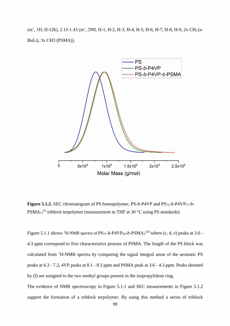
99
(m’, 1H, H-12b), 2.15-1.43 (m’, 29H, H-1, H-2, H-3, H-4, H-5, H-6, H-7, H-8, H-9, 2x CH3 (s-
BuLi), 3x CH3 (PSMA)).
Figure 5.1.2. SEC chromatogram of PS homopolymer, PS-b-P4VP and PS72-b-P4VP17-b-
PSMA1191 triblock terpolymer (measurement in THF at 30 °C using PS standards)
Figure 5.1.1 shows 1H-NMR spectra of PS71-b-P4VP26-b-PSMA3145 where (c, d, e) peaks at 3.6 -
4.3 ppm correspond to five characteristics protons of PSMA. The length of the PS block was
calculated from 1H-NMR spectra by comparing the signal integral areas of the aromatic PS
peaks at 6.3 - 7.2, 4VP peaks at 8.1 - 8.3 ppm and PSMA peak at 3.6 - 4.3 ppm. Peaks denoted
by (f) are assigned to the two methyl groups present in the isopropylidene ring.
The evidence of NMR spectroscopy in Figure 5.1.1 and SEC measurements in Figure 5.1.2
support the formation of a triblock terpolymer. By using this method a series of triblock

100
terpolymers with varying molecular weights and narrow molecular weight distributions were
successfully obtained as shown in Table 5.1. The yields range between 75-93 %. The polymers
are sorted in ascending order according to their PSMA content.
Table 5. 1. Composition and molecular weights of PS-b-P4VP-b-PSMA triblock terpolymer
Batch
number
Polymer Mn
(kg/mol)
P4VP
(wt%)
PSMA
(wt%)
Ð
300816-2 PS71-b-P4VP26-b-
PSMA3
145 26 3 1.05
190122 PS70-b-P4VP25-b-
PSMA
143 25 5 1.03
181128 PS69.3-b-P4VP25.5-b-
PSMA5.2
128 25.5 5.2 1.04
300816-1 PS73-b-P4VP20-b-
PSMA7
170 20 7 1.07
160816-2 PS73-b-P4VP19-b-
PSMA8
154 19 8 1.02
191015 PS71-b-P4VP17-b-
PSMA12
91 17 11 1.12
160816-1 PS69-b-P4VP20-b-
PSMA11
103 20 11 1.03
270716 PS64.8-b-P4VP23.6-b-
PSMA11.6
179 23.6 11.6 1.08

101
5.1.2 Bulk morphology of the triblock terpolymers
Annealed films obtained from solution casting were used to study the bulk morphology of the
triblock terpolymers. TEM analysis of PS-b-P4VP-b-PSMA triblock terpolymers (PS71-b-
P4VP26-b-PSMA3145, PS71-b-P4VP17-b-PSMA12
91) was performed by preparing ultrathin
sections of the respective triblock terpolymer film. For this purpose, a 7.5 wt% solution of
polymer was prepared in CHCl3, which is a common rather non-selective solvent for all the
three blocks. The solution dried for a week in a porcelain crucible under a constant vapor
atmosphere in a desiccator. The films were further annealed slowly from room temperature to
150˚C. Figure 5.1.3-a shows the TEM micrograph of a PS71-b-P4VP17-b-PSMA1291 triblock
terpolymer film in which only PS block was stained with RuO4. In this case, no typical or well-
defined block copolymer morphology could be evidenced, however, some bright domains of
PSMA could be observed in the darker PS matrix. Later the P4VP blocks of the same ultrathin
section were stained with iodine vapor. The result is depicted in Figure 5.1.3-b. In the presence
of iodine staining the PSMA block remains unstained, grey features demonstrate the PS block
which are distributed in the darker phase constituted by P4VP. Regular hexagonally packed
cylindrical structures predominate in PS71-b-P4VP26-b-PSMA3145 with no clear differentiation
of the phase composition as shown in Figure 5.1.4-a.
Figure 5.1.4-b shows an AFM image of a thin film of PS71-b-P4VP26-b-PSMA3145 prepared by
spin coated on a silicon wafer from a solution in chloroform and the long-range ordered
morphology was confirmed.

102
Figure 5.1.3. TEM micrographs of PS-b-P4VP-b-PSMA triblock terpolymer cast from
chloroform (a) PS71-b-P4VP17-b-PSMA1291 stained with RuO4 (b), with RuO4 and I2
Figure 5.1. 4. (a) TEM image of PS71-b-P4VP26-b-PSMA3145 stained with I2 (b) AFM height
image (in tapping mode) of the film surface of the asymmetric PS71-b-P4VP26-b-PSMA3145
triblock terpolymer

103
5.1.3 Preparation of the membrane by SNIPS
Among the parameters influencing the nanostructure of a membrane prepared by SNIPS the
(mixed) solvent interactions to different blocks and the concentration of the polymer are the
most important ones [188, 189].
Rational design of the selective solvent mixture plays a decisive role in the SNIPS process for
the desired morphology of block copolymer membranes. Solutions of block copolymer with
binary or ternary mixtures of solvents varying from volatile to non-volatile were prepared. The
volatile solvents THF and acetone are suitable for both PS and PSMA blocks, whereas DMF is
the preferred solvent for P4VP blocks according to the solubility parameters of the solvents and
blocks of the block copolymers.
Initially, we prepared membranes using different concentrations of binary solvent mixtures
THF/DMF: 50/50, 60/40, 70/30 wt%, however, the morphologies of the PS71-b-P4VP26-b-
PSMA3145 membranes did not show ordered pore structures, but rather dense regions with
random macropores were obtained (Figure 5.1.5).
Figure 5.1.5. SEM images of PS71-b-P4VP26-b-PSMA3145 membrane surfaces prepared from
different solutions: 22 wt% copolymer at 10 sec evaporation time in (a) 60/40 THF/DMF; (b)
50/50 THF/DMF; (c) 70/30 THF/DMF

104
Therefore, two types of ternary solvent mixtures THF/DMF/DOX and THF/DMF/acetone were
used for membrane casting. Self-assembly of the triblock terpolymer was not successful in
different compositions of THF/DMF/DOX (Figure 5.1.6).
Figure 5.1.6. SEM images of the PS71-b-P4VP26-b-PSMA3145 membranes cast from a 22 wt%
copolymer solution in (a) THF/DMF/DOX 1/1/1 (b) THF/DMF/DOX 40/30/30. The
evaporation time before immersion into the precipitant was 10 seconds.
However, the addition of acetone to the THF/DMF mixture directs the self-assembly of the
triblock terpolymer into highly ordered hexagonally packed cylinders with perpendicular
orientation. Different combinations of THF/DMF/acetone were examined, but only the mixture
of THF/DMF/acetone (50/30/20 wt%) leads to the desired nanostructure containing a narrow
pore size distribution with 10 s evaporation time as shown in Figure 5.1.7-a. THF and acetone
are selective volatile solvents for PS and PSMA while DMF is a more selective and much less
volatile solvent for P4VP. The abrupt change in the polymer solution concentration due to the
fast evaporation of acetone and THF favors the perpendicular ordering of the microdomains
and this differs from the solvent mixture containing less volatile DOX instead of acetone. Phillip
et al. [133] reported that fast evaporation conditions on the top layer can form perpendicular

105
cylinders templated by the copolymer self-assembly, while the underlying porous structure is
controlled by the polymer precipitation. The cross-section of the triblock terpolymer membrane
was imaged by SEM in Figure 5.1.7-b. The mean pore diameter of the integral asymmetric
membrane is 26 ± 3nm. It is advantageous to have a volatile co-solvent to study the effect of
evaporation time for PS71-b-P4VP26-b-PSMA3145 membranes.
Figure 5.1.7. SEM images of (a) top view and (b) cross-section of PS71-b-P4VP26-b-PSMA3145
membranes cast from 22 wt% solution in a THF/DMF/acetone: 50/30/20 wt%. Evaporation
time was 10 seconds before immersion in water
By increasing the evaporation time to 30 seconds, membrane regularity was partially destroyed
and a dense structure was formed predominately with only few open pores. Due to the longer
evaporation time the very well-ordered hexagonal cylindrical structure disappeared. The lying
cylindrical structure is much less porous and thus retards the solvent/non-solvent exchange.
(Figure 5.1.8)

106
Figure 5.1.8. Surface SEM images of PS71-b-P4VP26-b-PSMA3145 membranes cast from
solutions THF/DMF/Acetone: 50/30/20 wt%. (a) 20 seconds (b) 30 seconds evaporation time
before immersion into non-solvent bath.
It is observed that in-diffusion of non-solvent and out-diffusion of co-solvent becomes more
difficult by increasing the polymer concentration of the casting solution from 21-24 wt%. The
concentration of PS71-b-P4VP26-b-PSMA3145 was varied by keeping all the other parameters
constant. Membranes with a top isoporous layer (with cylindrical channels of approximately
220 nm length) followed by the spongy structure underneath, were obtained as shown in Figure
5.1.7 The high viscosity of the more concentrated casting solutions restricts the movement of
the polymeric chains due to the higher amount of the polymerand perhaps influences the final
membrane morphology. (Figure 5.1.9)

107
Figure 5.1.9. Surface SEM images of PS71-b-P4VP26-b-PSMA3145 membranes cast from 21
wt%, 23 wt%, and 24 wt% terpolymer solutions in THF/DMF/Acetone: 50/30/20 wt%. The
evaporation time before immersion into the precipitant was 10 s.
5.1.4 Post-modification of PS71-b-P4VP17-b-PSMA1291 triblock terpolymer
The triblock terpolymers synthesized in this study with a longer third hydrophobic block
(PSMA) suffer difficulties for membrane formation via SNIPS. Based on previous findings [45,
190], this is probably due to the shorter hydrophilic P4VP block, which cannot compensate for
the hydrophobic nature of the PSMA block.
The PS71-b-P4VP17-b-PSMA1291 triblock terpolymer was treated with 1M HCl solution at 50 °C
for 3 days to remove the acetonide moiety of PSMA blocks. The acid treated polymer was
stirred in 0.1M NaOH solution for 45 minutes to completely deprotonate the quaternized P4VP
blocks. Finally, the triblock terpolymer was treated with deionized water and dried in a vacuum
oven at 50 °C. The procedure was monitored by 1H-NMR to ensure the removal of the
isopropylidene acetal group. After each step the polymers were re-dissolved in deuterated
solvents and spectra were recorded. Quaternization of the P4VP was monitored by the solubility
of the polymer in CDCl3 (quaternized polymers were not dissolved in CDCl3). The complete
acidic hydrolysis of the ketal moiety of PSMA block shown in the Section 3.3.2.

108
1H-NMR spectra of PS71-b-P4VP17-b-PGMA1291 is shown in Figure 5.1.10 after acidic
hydrolysis of the PSMA block. The appearance of two signals at (f) corresponds to two hydroxyl
groups (-OH) of GMA units whereas peaks at c, d, e represent five protons of the solketal
moiety, which are shifted up field due to the replacement of the carbon atom with a hydrogen
atom. PS71-b-P4VP17-b-PGMA1291 was also protonated by HCL during the acidic hydrolysis of
the ketal moieties of the PSMA block, resulting in temporarily charged PS-b-PQ4VP-b-PGMA
(PQ4VP stands for quarternized P4VP) because of quaternization of the 4-vinyl pyridine
moiety. However, the temporary quarternized P4VP block was deprotonated successfully by
stirring the polymer in 0.1 M sodium hydroxide solution.
Figure 5.1.10. 1H-NMR spectrum of the linear triblock terpolymer PS71-b-P4VP17-b-PGMA1291
in DMF-d7

109
1H-NMR (DMF-d7, 20 °C, 300 MHz, TMS)
δ [ppm] = 8.3 (m’ 2H, H-14, H-15), 7.4-6.7 (m’, 18H, H-13, H16, H17, H-18, H-19, arom.
H(DPE)), 5.7 (s‘, DPE), 5.3 (s’, 1H, H-14), 5.04 (s’, 1H, H-13), 4.28-3.7 (m’, 5H, H-10, H-11,
H-12), 2.15-1.43 (m’, 23H, H-1, H-2, H-3, H-4, H-5, H-6, H-7, H-8, H-9, 2x CH3 (s-BuLi), 1
x CH3 (PGMA)).
5.1.5 Membrane fabrication after post-modification of triblock terpolymer
Apparently, the amphiphilic behavior plays a crucial role in the self-assembly and pore
formation during the phase inversion process. After the acidic hydrolysis of PS71-b-P4VP17-b-
PSMA1291 triblock terpolymer, the amphiphilicity of the whole polymer increased due to the
appearance of hydroxyl groups in PS71-b-P4VP17-b-PGMA1291, resulting into a hexagonally
oriented cylindrical porous membrane as shown in Figure 5.1.11. It is assumed that the
hydrophilic short block at the end of the pore-forming block (P4VP) enhances the formation of
a good membrane structure, while the addition of a hydrophobic block tends to suppress the
formation of a porous membrane structure. Only if the P4VP block is large enough it can
overcome the influence of the hydrophobic PSMA block and a membrane with highly oriented
pores can be obtained.

110
Figure 5.1.11. SEM images of (a) PS71-b-P4VP17-b-PSMA1291 membrane (b) PS71-b-P4VP17-
b-PGMA1291 membrane obtained after acidic hydrolysis. The evaporation time before
immersion into water bath was 10 s.
This is in agreement with our previous results for a PS-b-PSMA and the corresponding
hydrolyzed PS-b-PGMA diblock copolymer, where only the latter one yielded the isoporous
membranes by applying SNIPS [190].
5.1.6 Post-modification of PS71-b-P4VP26-b-PSMA3145 membranes.
The same procedure mentioned in Section 5.1.4 was followed for the post-modification of
PSMA block of PS71-b-P4VP26-b-PSMA3145 triblock terpolymer membranes (in solid state).
5.2 Comparison of the performance of membranes
In this chapter, a comparison of the performance of the membranes prepared before (PS-b-
P4VP-b-PSMA) and after acidic hydrolysis (PS-b-P4VP-b-PGMA) will be discussed.

111
5.2.1 Comparison of contact angle measurements
The hydrophilicity of the membrane is characterized by water contact angle. The sessile drop
method was used to investigate the dynamic contact angle of PS71-b-P4VP26-b-PSMA3145 and
PS71-b-P4VP26-b-PGMA3145 membranes. Figure 5.2.1 shows the contact angles or sinking of a
water droplet with time on/into the membrane surfaces before and after hydrolysis of PSMA
blocks. It can be seen that the water contact angle of PS71-b-P4VP26-b-PSMA3145 membrane
surface is definitely higher as compared to the PS71-b-P4VP26-b-PGMA3145 membranes. The
lower contact angle value for PS71-b-P4VP26-b-PGMA3145 membranes surfaces indicates the
presence of hydroxyl (–OH) groups.
Figure 5.2.1. Dynamic contact angle measurements of water droplets (2µL each) onto the PS71-
b-P4VP26-b-PSMA3145 (black squares) and PS71-b-P4VP26-b-PGMA3
145 (red circles)
membranes

112
5.2.2 Water permeation and pH responsive behavior
Block copolymer membranes with high porosity, homogeneous pore size, and tunable chemical
properties hold tremendous potential as robust, efficient, and highly selective separation
membranes. We tested the integral asymmetric PS71-b-P4VP26-b-PGMA3145 membrane for
ultrafiltration and analyzed the separation performance of the hexagonally organized isoporous
structure by comparing it with the pristine PS71-b-P4VP26-b-PSMA3145 membrane. The
permeance of the membranes before and after hydrolysis was measured in dead-end mode at 2
bar trans-membrane pressure. It is reported in the literature that improvement of hydrophilicity
has an influence on the pure water flux [191].
Figure 5.2.2. SEM images of pristine PS71-b-P4VP26-b-PSMA3145 membrane before acidic
hydrolysis and (b) PS71-b-P4VP26-b-PGMA3145 membrane.
The initial permeance of the pristine PS71-b-P4VP26-b-PSMA3145 and hydrolyzed PS71-b-
P4VP26-b-PGMA3145 membrane is 390 ± 25 L m-2 bar-1 h-1 and 485 ± 10 L m-2 bar-1 h-1,
respectively. Compared to the pristine membrane, the hydrolyzed membrane decorated with

113
hydrophilic PGMA not only has a higher flux, but also appears to have stable permeance. The
pore diameters of both the membranes before and after hydrolysis are rather similar (Figure
5.2.2). These increased permeability results are in accordance with the contact angle
measurements, the more hydrophilic surfaces lead to an increased wetting of the porous
structure [192].
The stimuli responsive behavior of the triblock terpolymer membrane PS71-b-P4VP26-b-
PGMA3145 was investigated by the influence of the pH value on water flux. Since P4VP can be
protonated at low pH, due to the swelling of the positively charged P4VP blocks, a decrease in
the size of the pores was observed whereas the highest water flux was observed at pH 7. The
P4VP block behaves like a polyelectrolyte at low pH (Figure 5.2.3).
Figure 5.2.3. Water permeability of PS71-b-P4VP26-b-PGMA3145 membrane measured at
various pH, at pH ˃ 4 high water permeability was observed, due to deswelling of the
deprotonated P4VP blocks at larger pH, leading to their collapse on the pore walls

114
5.2.3 BSA retention measurements
Ultrafiltration membranes suffer from organic and biological fouling, which impede the
performance in long-term use [41, 193, 194]. For studying the properties of our membranes,
retention and adsorption measurements were carried out. The retention measurements were
carried out by using 1 mg/1 mL bovine serum albumin (BSA, Sigma-Aldrich, USA) solution at
pH 7.4. The isoelectric point is at pH 5.2. BSA shows a negative overall charge at the given pH
when taking into account the isoelectric point of the protein. The hydrodynamic diameter of
BSA (7.6 nm as stated by the supplier) is much below the pore size; its retention depends mainly
on the interaction with the membrane, rather than being a size effect. The results in Table 5.2
show that the retention rate of BSA for PS71-b-P4VP26-b-PSMA3145 membrane was 90%
whereas only 24% retention was observed for hydrolyzed PS71-b-P4VP26-b-PGMA3145
membrane. The low retention rate to the protein demonstrates that increasing the membrane
hydrophilicity by incorporating hydroxyl groups containing PGMA results in a decreased
fouling [195].
Table 5. 2. Retention results from experiments in a 1 mg/1 mL BSA solution in (PBS buffer
pH = 7.4).
Membrane/BSA % BSA retention Average pore diameter/size
(nm)
PS71-b-P4VP26-b-PSMA3145
PS71-b-P4VP26-b-PGMA3145
BSA
90
24
_
26 ± 3 a
26 ± 4 a
7.6 [196]
a determined by using the software analysis (Olympus Soft Imaging Solutions) of the SEM
surface images

115
5.2.4 Static adsorption of hemoglobin
Further on, the high hydrophilicity and the antifouling behavior of PS-b-P4VP, pristine PS71-b-
P4VP26-b-PSMA3145, and modified PS71-b-P4VP26-b-PGMA3
145 membranes were confirmed by
static hemoglobin adsorption experiments at 25 ˚C in PBS buffer (pH 7.4). The hydrodynamic
diameter of hemoglobin (IEP = 6.8) is 6.4 nm as stated by the supplier. The results of the
adsorption experiments are shown in Figure 5.2.4.The modified surfaces were tested in
comparison to the untreated triblock terpolymer surfaces.
The highest hemoglobin adsorption found for PS74-b-P4VP26162 membranes can be attributed to
chelation of the iron ions from hemoglobin by the free electron pair of the P4VP nitrogen atom
[197, 198], whereas a decrease in adsorption value was observed when P4VP pores were
covered with a hydrophobic PSMA block. At the given pH value, hemoglobin is not
significantly charged (IEP = 6.8) and the membranes are also neutral, which allows the
adsorption of hemoglobin to occur because of the hydrophobic/hydrophilic balance of the
membranes. PS-b-P4VP-b-PGMA membranes decorated with hydrophilic PGMA block
showed the smallest hemoglobin adsorption among all tested membranes due to strong
hydration of the surface, which gives the surface an antifouling property [199]. This significant
improvement in the protein adsorption resistance has a profound effect on the long-term
filtration of proteins.

116
Figure 5.2.4. Protein adsorption of hemoglobin of PS74-b-P4VP26162, PS71-b-P4VP26-b-
PSMA3145and PS71-b-P4VP26-b-PGMA3
145 membranes at pH 7.4
In this chapter, a series of novel triblock terpolymers of PS-b-P4VP-b-PSMA with varying
compositions were synthesized by living sequential anionic polymerization with low dispersity
values (Ð =1.06 – 1.12). It was demonstrated that isoporous integral asymmetric membranes
could be prepared successfully via SNIPS, if the hydrophobic PSMA block was not too long
with respect to the P4VP block by using the ternary solvent system (THF/DMF/acetone) for
this novel PS-b-P4VP-b-PSMA triblock terpolymer. The conversion of PSMA into PGMA
block by acidic hydrolysis did not affect the membrane morphology. The amphiphilic PS-b-
P4VP-b-PGMA triblock terpolymer membranes showed a significant decrease in retention and
adsorption of proteins as compared to more hydrophobic PS-b-P4VP-b-PSMA membranes and
PS-b-P4VP membranes. The results of contact angle and water flux measurements also confirm
the more hydrophilic behavior of PS-b-P4VP-b-PGMA triblock terpolymer membranes. This

117
indicates the strong and positive influence of the third hydrophilic block on the membrane
properties.

118
Chapter 6: Summary and outlook
6.1. Summary and outlook
The aim of this work was to develop integral asymmetric membranes via self-assembly and
non-solvent induced phase inversion process from novel diblock and triblock copolymers.
Diblock copolymers of polystyrene-block-poly(solketal methacrylate) (PS-b-PSMA) of
different composition were successfully synthesized by sequential living anionic
polymerization whereas polystyrene-b-poly(glyceryl methacrylate) (PS-b-PGMA) were
obtained by acid hydrolysis of the acetonide groups of the poly(solketal methacrylate) (PSMA)
blocks into poly(glyceryl methacrylate) (PGMA). By utilizing the binary THF/DMF and ternary
THF/DMF/DOX solvent system, integral asymmetric membranes of PS-b-PGMA via self-
assembly and non-solvent-induced phase separation process could be achieved. Later, a
comparative study of amphiphilic PS-b-PGMA and hydrophobic PS-b-PSMA diblock
copolymers for the development of isoporous integral asymmetric membranes was presented.
Within this study, no suitable solvents were found to prepare isoporous membranes from the
PS-b-PSMA diblock copolymer. This will require a more subtle choice of solvents, as the level
of selectivity of a solvent and non-solvent is much less pronounced in a block copolymer
composed of similar polar (or nonpolar) blocks.
Further, static protein adsorption measurements were performed to analyze the increase in
hydrophilic behavior of isoporous membranes of PS-b-PGMA and were compared with a PS-
b-P4VP system of similar molecular weight and block ratio. Different nanofillers were added
to the PS-b-PGMA diblock copolymer system and the hybrid membranes fabricated via SNIPS.
For the first time, PS-b-P4VP-b-PSMA triblock terpolymers with varying compositions were
successfully synthesized by sequential living anionic polymerization. Composite membranes of
PS-b-P4VP-b-PSMA and PS-b-P4VP-b-PGMA triblock terpolymers with ordered hexagonally
packed cylindrical pores were developed. The morphology of the membranes was studied with

119
scanning electron microscopy (SEM) and atomic force microscopy (AFM). PS-b-P4VP-b-
PSMA triblock terpolymer membranes were further treated with acid to get polystyrene-b-
poly(4-vinylpyridine)-block-poly(glyceryl methacrylate) (PS-b-P4VP-b-PGMA). An increase
in the hydrophilicity was observed after treatment of isoporous membranes from PS-b-P4VP-
b-PSMA, through acidic hydrolysis of the hydrophobic poly(solketal methacrylate) PSMA
block into a hydrophilic poly(glyceryl methacrylate) PGMA block, which contains two
neighbored hydroxyl (–OH) groups per repeating unit. Notably, the pristine porous membrane
structure could be maintained even after acidic hydrolysis. The membrane properties were
analyzed further by contact angle, protein retention, and adsorption measurements. It was found
that membranes containing hydroxyl groups (PS-b-P4VP-b-PGMA) show a stable and higher
water permeance than membranes without hydroxyl groups (PS-b-P4VP-b-PSMA), what is due
to the increase in hydrophilicity.
The new functional triblock terpolymer PS-b-P4VP-b-PGMA showed significantly lower (cut
off) retention and fouling compared to the more hydrophobic PS-b-P4VP-b-PSMA precursor
membrane and also compared to a PS-b-P4VP membrane, indicating a strong and positive
influence of the third hydrophilic block on the membrane properties. Thus, the introduction of
a highly functional and hydrophilic block containing repeating units with two hydroxyl groups
could be carried out, which allows for a large variety of further post-modification reactions.

120
6.2. Zusammenfassung und Ausblick
Das Ziel dieser Arbeit war die Entwicklung integraler asymmetrischer Membranen durch Self-
assembly und nicht lösungsmittelinduzierte Phaseninversion aus neuartigen Diblock und
Triblockcopolymeren. Diblockcopolymere aus Polystyrol-block-poly(solketalmethacrylat)
(PS-b-PSMA) unterschiedlicher Zusammensetzung wurden erfolgreich durch sequentielle
lebende anionische Polymerisation synthetisiert, Polystyrol-b-poly(glyceryl methacrylat) (PS-
b-PGMA) wurde durch anschließende Säurehydrolyse der Acetonidgruppen der Polysolketal
methacrylat (PSMA)-Blöcke zu (PGMA) erhalten. Unter Verwendung des binären THF/DMF-
und ternären THF/DMF/DOX-Lösungsmittelsystems konnten integrale asymmetrische
Membranen von PS-b-PGMA mittels Self-assembly und Nicht-lösemittelinduzierten
Phaseninversionsprozess erfolgreich hergestellt werden. Im Folgenenden wurden amphiphiles
PS-b-PGMA und hydrophobes PS-b-PSMA Diblockcopolymere zur Entwicklung isoporöser
integraler asymmetrischer Membranen untersucht und charakterisiert. Innerhalb dieser Studie
wurden keine geeigneten Lösungsmittel gefunden, zur Herstelung von isoporösen Membranen
aus PS-b-PSMA-Diblockcopolymer. Dies erfordert weitere Untersuchungen, da die Wahl eines
passenden Lösemittels und eines Nichtlösemittels für ein nicht-amphiphiles Blockcopolymer,
das aus ähnlichen polaren (oder unpolaren) Blöcken besteht, wenig untersucht ist und eine
Vielzahl an möglichen Kombinationen aus Nicht- und Lösemitteln gibt.
Des Weiteren wurden statische Proteinadsorptionsmessungen durchgeführt, um die Zunahme
des hydrophilen Verhaltens von isoporösen Membranen von PS-b-PGMA zu analysieren, diese
Ergebnisse wurden mit dem PS-b-P4VP-System mit ähnlichem Molekulargewicht und
Blockverhältnis verglichen. Dem PS-b-PGMA-Diblockcopolymersystem und den über SNIPS
hergestellten Hybridmembranen wurden verschiedene Nanofüllstoffe zugesetzt. Erstmals
wurden PS-b-P4VP-b-PSMA-Triblockterpolymere mit unterschiedlichen Zusammensetzungen
erfolgreich durch sequentielle lebende anionische Polymerisation synthetisiert.

121
Verbundmembranen von PS-b-P4VP-b-PSMA und PS-b-P4VP-b-PGMA
Triblockterpolymeren mit geordneten hexagonal gepackten zylindrischen Poren konnten
erfolgreich hergestellt werden. Die Morphologie der Membranen wurde per
Rasterelektronenmikroskopie (REM) und Rasterkraftmikroskopie (AFM) untersucht. PS-b-
P4VP-b-PSMA Triblockterpolymer Membranen wurden zusätzlich mit Säure behandelt, um
Polystyrol-b-poly(4-vinylpyridin)-block-Poly(glyceryl methacrylat) (PS-b-P4VP-b-PGMA) zu
erhalten. Eine Zunahme der Hydrophilie wurde nach Behandlung von isoporösen Membranen
aus PS-b-P4VP-b-PSMA durch saure Hydrolyse des hydrophoben Poly(solketal methacrylat)
PSMA-Blocks zu einem hydrophilen Poly(glyceryl methacrylat) PGMA-Block beobachtet,
welches zwei benachbarte Hydroxylgruppen (-OH) pro Wiederholungseinheit enthält. Die
Membraneigenschaften wurden durch Kontaktwinkel-, Proteinrückhaltungs- und
Adsorptionsmessungen charakterisiert. Bemerkenswert ist, dass die isoporöse
Membranstruktur auch nach der sauren Hydrolyse beibehalten werden. Für Membranen mit
Hydroxylgruppen (PS-b-P4VP-b-PGMA) wurde eine stabilere und höhere Permeanz gemessen
im Vergleich zu Membranen ohne Hydroxylgruppen (PS-b-P4VP-b-PSMA), Dies kann auf die
Zunahme der Hydrophilie zurückgeführt werden.
Das neue funktionelle Triblockterpolymer PS-b-P4VP-b-PGMA zeigte im Vergleich zur
hydrophoberen PS-b-P4VP-b-PSMA-Vorläufermembran eine signifikant bessere Rückhaltung
und reduziertes Fouling, und im Vergleich zu einer PS-b-P4VP-Membran ebenfalls, was auf
den positiven Einfluss des dritten hydrophilen Blocks in die Membran zurückzuführen ist. Die
erfolgreiche Integration eines hochfunktionellen und hydrophilen Blocks, mit wiederholenden
Einheiten aus zwei Hydroxylgruppen, ermöglicht eine große Vielfalt weiterer
Postmodifizierungsreaktionen.

122
Chapter 7: References
[1] M.A. Shannon, P.W. Bohn, M. Elimelech, J.G. Georgiadis, B.J. Mariñas, A.M. Mayes, Science and
technology for water purification in the coming decades, Nature 452(7185) (2008) 301-310.
[2] M. Elimelech, The global challenge for adequate and safe water, Journal of Water Supply: Research
and Technology-Aqua 55(1) (2006) 3-10.
[3] G.M. Geise, H.-S. Lee, D.J. Miller, B.D. Freeman, J.E. McGrath, D.R. Paul, Water purification by
membranes: The role of polymer science, Journal of Polymer Science Part B: Polymer Physics 48(15)
(2010) 1685-1718.
[4] M. Elimelech, W.A. Phillip, The Future of Seawater Desalination: Energy, Technology, and the
Environment, Science 333(6043) (2011) 712-717.
[5] S.P. Nunes, P.Z. Culfaz-Emecen, G.Z. Ramon, T. Visser, G.H. Koops, W. Jin, M. Ulbricht, Thinking the
future of membranes: Perspectives for advanced and new membrane materials and manufacturing
processes, Journal of Membrane Science 598 (2020) 117761.
[6] X. Yu, Y. Zhu, C. Cheng, T. Zhang, X. Wang, B.S. Hsiao, Novel thin-film nanofibrous composite
membranes containing directional toxin transport nanochannels for efficient and safe hemodialysis
application, Journal of Membrane Science 582 (2019) 151-163.
[7] J.R. Werber, C.O. Osuji, M. Elimelech, Materials for next-generation desalination and water
purification membranes, Nature Reviews Materials 1(5) (2016) 16018.
[8] H.K. Lonsdale, U. Merten, R.L. Riley, Transport properties of cellulose acetate osmotic membranes,
Journal of Applied Polymer Science 9(4) (1965) 1341-1362.
[9] K.T. Sanders, M.E. Webber, Evaluating the energy consumed for water use in the United States,
Environmental Research Letters 7(3) (2012) 034034.
[10] U. Merten, Flow Relationships in Reverse Osmosis, Industrial & Engineering Chemistry
Fundamentals 2(3) (1963) 229-232.
[11] W.R. Bowen, A.W. Mohammad, Characterization and Prediction of Nanofiltration Membrane
Performance—A General Assessment, Chemical Engineering Research and Design 76(8) (1998) 885-
893.
[12] W.R. Bowen, A.W. Mohammad, N. Hilal, Characterisation of nanofiltration membranes for
predictive purposes — use of salts, uncharged solutes and atomic force microscopy, Journal of
Membrane Science 126(1) (1997) 91-105.
[13] R. van Reis, A. Zydney, Bioprocess membrane technology, Journal of Membrane Science 297(1)
(2007) 16-50.
[14] Y. Zhang, J.L. Sargent, B.W. Boudouris, W.A. Phillip, Nanoporous membranes generated from self-
assembled block polymer precursors: Quo Vadis?, Journal of Applied Polymer Science 132(21) (2015).

123
[15] C.G. Gamys, J.-M. Schumers, C. Mugemana, C.-A. Fustin, J.-F. Gohy, Pore-Functionalized
Nanoporous Materials Derived from Block Copolymers, Macromolecular Rapid Communications 34(12)
(2013) 962-982.
[16] M. Tasaka, T. Okano, T. Fujimoto, Mass transport through charge-micromosaic membranes,
Journal of Membrane Science 19(3) (1984) 273-288.
[17] Z. Zhang, M.M. Rahman, C. Abetz, A.-L. Höhme, E. Sperling, V. Abetz, Chemically Tailored
Multifunctional Asymmetric Isoporous Triblock Terpolymer Membranes for Selective Transport,
Advanced Materials n/a(n/a) 1907014.
[18] Z. Zhang, M.M. Rahman, C. Abetz, V. Abetz, High-performance asymmetric isoporous
nanocomposite membranes with chemically-tailored amphiphilic nanochannels, Journal of Materials
Chemistry A 8(19) (2020) 9554-9566.
[19] Y. Zhang, N.E. Almodovar-Arbelo, J.L. Weidman, D.S. Corti, B.W. Boudouris, W.A. Phillip, Fit-for-
purpose block polymer membranes molecularly engineered for water treatment, npj Clean Water 1(1)
(2018) 2.
[20] E.A. Jackson, M.A. Hillmyer, Nanoporous Membranes Derived from Block Copolymers: From Drug
Delivery to Water Filtration, ACS Nano 4(7) (2010) 3548-3553.
[21] J. Hahn, J.I. Clodt, V. Filiz, V. Abetz, Protein separation performance of self-assembled block
copolymer membranes, RSC Advances 4(20) (2014) 10252-10260.
[22] B. Sutisna, G. Polymeropoulos, E. Mygiakis, V. Musteata, K.V. Peinemann, D.M. Smilgies, N.
Hadjichristidis, S.P. Nunes, Artificial membranes with selective nanochannels for protein transport,
Polymer Chemistry 7(40) (2016) 6189-6201.
[23] M. Barboiu, A. Gilles, From Natural to Bioassisted and Biomimetic Artificial Water Channel
Systems, Accounts of Chemical Research 46(12) (2013) 2814-2823.
[24] D.J. Miller, D.R. Dreyer, C.W. Bielawski, D.R. Paul, B.D. Freeman, Surface Modification of Water
Purification Membranes, Angewandte Chemie International Edition 56(17) (2017) 4662-4711.
[25] W. Fu, T. Pei, Y. Mao, G. Li, Y. Zhao, L. Chen, Highly hydrophilic poly(vinylidene fluoride)
ultrafiltration membranes modified by poly(N-acryloyl glycinamide) hydrogel based on multi-hydrogen
bond self-assembly for reducing protein fouling, Journal of Membrane Science 572 (2019) 453-463.
[26] S. Rajesh, A. Jayalakshmi, S. Senthilkumar, H.S.H. Sankar, D.R. Mohan, Performance Evaluation of
Poly(amide-imide) Incorporated Cellulose Acetate Ultrafiltration Membranes in the Separation of
Proteins and Its Fouling Propensity by AFM Imaging, Industrial & Engineering Chemistry Research
50(24) (2011) 14016-14029.
[27] E. Ostuni, R.G. Chapman, R.E. Holmlin, S. Takayama, G.M. Whitesides, A Survey of
Structure−Property Relationships of Surfaces that Resist the Adsorption of Protein, Langmuir 17(18)
(2001) 5605-5620.

124
[28] S. Kang, A. Asatekin, A.M. Mayes, M. Elimelech, Protein antifouling mechanisms of PAN UF
membranes incorporating PAN-g-PEO additive, Journal of Membrane Science 296(1) (2007) 42-50.
[29] S. Saleem, S. Rangou, C. Abetz, V. Filiz, V. Abetz, Isoporous Membranes from Novel Polystyrene-b-
poly(4-vinylpyridine)-b-poly(solketal methacrylate) (PS-b-P4VP-b-PSMA) Triblock Terpolymers and
Their Post-Modification, Polymers 12(1) (2019).
[30] A. Lee, J.W. Elam, S.B. Darling, Membrane materials for water purification: design, development,
and application, Environmental Science: Water Research & Technology 2(1) (2016) 17-42.
[31] M. Ulbricht, Advanced functional polymer membranes, Polymer 47(7) (2006) 2217-2262.
[32] G. Tealdo, G. Castello, G. D'Amato, S. Munari, Water—glycerol permeation through styrene-
grafted and sulphonated PTFE membranes, Journal of Membrane Science 11(1) (1982) 3-9.
[33] H. Yamagishi, J.V. Crivello, G. Belfort, Development of a novel photochemical technique for
modifying poly (arylsulfone) ultrafiltration membranes, Journal of Membrane Science 105(3) (1995)
237-247.
[34] A.V.R. Reddy, D.J. Mohan, A. Bhattacharya, V.J. Shah, P.K. Ghosh, Surface modification of
ultrafiltration membranes by preadsorption of a negatively charged polymer: I. Permeation of water
soluble polymers and inorganic salt solutions and fouling resistance properties, Journal of Membrane
Science 214(2) (2003) 211-221.
[35] T.-H. Bae, T.-M. Tak, Preparation of TiO2 self-assembled polymeric nanocomposite membranes
and examination of their fouling mitigation effects in a membrane bioreactor system, Journal of
Membrane Science 266(1) (2005) 1-5.
[36] B.C. Johnson, İ. Yilgör, C. Tran, M. Iqbal, J.P. Wightman, D.R. Lloyd, J.E. McGrath, Synthesis and
characterization of sulfonated poly(acrylene ether sulfones), Journal of Polymer Science: Polymer
Chemistry Edition 22(3) (1984) 721-737.
[37] T. Matsuda, S. Ito, Surface coating of hydrophilic-hydrophobic block co-polymers on a
poly(acrylonitrile) haemodialyser reduces platelet adhesion and its transmembrane stimulation,
Biomaterials 15(6) (1994) 417-422.
[38] D. Rana, T. Matsuura, R.M. Narbaitz, Novel hydrophilic surface modifying macromolecules for
polymeric membranes: Polyurethane ends capped by hydroxy group, Journal of Membrane Science
282(1) (2006) 205-216.
[39] M. Radjabian, V. Abetz, Tailored Pore Sizes in Integral Asymmetric Membranes Formed by Blends
of Block Copolymers, Advanced Materials 27(2) (2015) 352-355.
[40] X. Ma, Y. Su, Q. Sun, Y. Wang, Z. Jiang, Preparation of protein-adsorption-resistant
polyethersulfone ultrafiltration membranes through surface segregation of amphiphilic comb
copolymer, Journal of Membrane Science 292(1) (2007) 116-124.

125
[41] L.F. Hancock, S.M. Fagan, M.S. Ziolo, Hydrophilic, semipermeable membranes fabricated with
poly(ethylene oxide)–polysulfone block copolymer, Biomaterials 21(7) (2000) 725-733.
[42] J. Hahn, V. Filiz, S. Rangou, J. Clodt, A. Jung, K. Buhr, C. Abetz, V. Abetz, Structure formation of
integral-asymmetric membranes of polystyrene-block-Poly(ethylene oxide), Journal of Polymer
Science Part B: Polymer Physics 51(4) (2013) 281-290.
[43] C. Burguière, C. Chassenieux, B. Charleux, Characterization of aqueous micellar solutions of
amphiphilic block copolymers of poly(acrylic acid) and polystyrene prepared via ATRP. Toward the
control of the number of particles in emulsion polymerization, Polymer 44(3) (2003) 509-518.
[44] S. Schöttner, H.-J. Schaffrath, M. Gallei, Poly(2-hydroxyethyl methacrylate)-Based Amphiphilic
Block Copolymers for High Water Flux Membranes and Ceramic Templates, Macromolecules 49(19)
(2016) 7286-7295.
[45] A. Jung, V. Filiz, S. Rangou, K. Buhr, P. Merten, J. Hahn, J. Clodt, C. Abetz, V. Abetz, Formation of
Integral Asymmetric Membranes of AB Diblock and ABC Triblock Copolymers by Phase Inversion,
Macromolecular Rapid Communications 34(7) (2013) 610-615.
[46] H. Mori, A. Hirao, S. Nakahama, K. Senshu, Synthesis and Surface Characterization of Hydrophilic-
Hydrophobic Block Copolymers Containing Poly(2,3-dihydroxypropyl methacrylate), Macromolecules
27(15) (1994) 4093-4100.
[47] H. Zhang, E. Ruckenstein, A Novel Successive Route to Well-Defined Water-Soluble Poly(2,3-
dihydroxypropyl methacrylate) and Amphiphilic Block Copolymers Based on an Osmylation Reaction,
Macromolecules 33(13) (2000) 4738-4744.
[48] M.F. Refojo, Glyceryl methacrylate hydrogels, Journal of Applied Polymer Science 9(9) (1965)
3161-3170.
[49] J. Hahn, J.I. Clodt, C. Abetz, V. Filiz, V. Abetz, Thin Isoporous Block Copolymer Membranes: It Is All
about the Process, ACS Applied Materials & Interfaces 7(38) (2015) 21130-21137.
[50] K. Hong, D. Uhrig, J.W. Mays, Living anionic polymerization, Current Opinion in Solid State and
Materials Science 4(6) (1999) 531-538.
[51] N. Hadjichristidis, H. Iatrou, S. Pispas, M. Pitsikalis, Anionic polymerization: High vacuum
techniques, Journal of Polymer Science Part A: Polymer Chemistry 38(18) (2000) 3211-3234.
[52] M. Szwarc, M. Levy, R. Milkovich, POLYMERIZATION INITIATED BY ELECTRON TRANSFER TO
MONOMER. A NEW METHOD OF FORMATION OF BLOCK POLYMERS1, Journal of the American
Chemical Society 78(11) (1956) 2656-2657.
[53] T.R. Darling, T.P. Davis, M. Fryd, A.A. Gridnev, D.M. Haddleton, S.D. Ittel, R.R. Matheson Jr., G.
Moad, E. Rizzardo, Living polymerization: Rationale for uniform terminology, Journal of Polymer
Science Part A: Polymer Chemistry 38(10) (2000) 1706-1708.
[54] R.P.Q. H.L. Hsieh, Anionic Polymerization: Principles and Practical Applications;, New York, 1996.

126
[55] O.W. Webster, Living Polymerization Methods, Science 251(4996) (1991) 887.
[56] K.V. Peinemann, Nunes. S.P, Membrane Technology in the Chemical Industry, WILEY-VCH verlag
GmbH & Co. KGaA, Weinheim, Germany, 2006.
[57] R.P. Quirk, B. Lee, Adducts of Polymeric Organolithiums with 1,1-Diphenylethylene. Rates of
Formation and Crossover to Styrene and Diene Monomers, Macromolecular Chemistry and Physics
204(14) (2003) 1719-1737.
[58] D.M. Wiles, S. Bywater, Polymerization of methyl methacrylate initiated by 1,1-diphenylhexyl
lithium, Transactions of the Faraday Society 61(0) (1965) 150-158.
[59] T. Fox, B. Garrett, W. Goode, S. Gratch, J. Kincaid, A, Spell and. J. D. Stroupe, J. Am. Chem. Soc 80
(1958) 1768.
[60] S. Antoun, P. Teyssié, R. Jérôme, Lithium Diisopropylamide as Initiator for the Anionic
Polymerization of Methacrylates, Macromolecules 30(6) (1997) 1556-1561.
[61] K.M. A.H.E. Müller, "Structure of Carbanion", in Controlled and Living Polymerizations, Wiley-VCH,
2009.
[62] R.M. Fuoss, Ionic Association. III. The Equilibrium between Ion Pairs and Free Ions, Journal of the
American Chemical Society 80(19) (1958) 5059-5061.
[63] S. Winstein, E. Clippinger, A.H. Fainberg, G.C. Robinson, SALT EFFECTS AND ION-PAIRS IN
SOLVOLYSIS1, Journal of the American Chemical Society 76(9) (1954) 2597-2598.
[64] C.A. Finch, Encyclopedia of polymer science and engineering, 2nd edition volume 2, anionic
polymerisation to cationic polymerisation editor-in-chief Jacqueline I. Kroschwitz, Editors H. F. Mark,
N. M. Bikales, C. G. Overberger and G. Menges, Wiley-Interscience, New York, 1985. , British Polymer
Journal 17(4) (1985) 377-377.
[65] P.J. Flory, Principles of Polymer Chemistry, Cornell University Press, Ithaca, London, 1953.
[66] S. Nakahama, A. Hirao, Protection and polymerization of functional monomers: Anionic living
polymerization of protected monomers, Progress in Polymer Science 15(2) (1990) 299-335.
[67] A. Hirao, S. Nakahama, Anionic living polymerization of monomers with functional silyl groups,
Progress in Polymer Science 17(3) (1992) 283-317.
[68] A. Hirao, S. Loykulnant, T. Ishizone, Recent advance in living anionic polymerization of
functionalized styrene derivatives, Progress in Polymer Science 27 (2002) 1399-1471.
[69] A. Matsuo, T. Watanabe, A. Hirao, Synthesis of Well-Defined Dendrimer-like Branched Polymers
and Block Copolymer by the Iterative Approach Involving Coupling Reaction of Living Anionic Polymer
and Functionalization, Macromolecules 37(17) (2004) 6283-6290.
[70] R. Advincula, Q. Zhou, M. Park, S. Wang, J. Mays, G. Sakellariou, S. Pispas, N. Hadjichristidis,
Polymer Brushes by Living Anionic Surface Initiated Polymerization on Flat Silicon (SiOx) and Gold
Surfaces: Homopolymers and Block Copolymers, Langmuir 18(22) (2002) 8672-8684.

127
[71] Q. Zhou, X. Fan, C. Xia, J. Mays, R. Advincula, Living Anionic Surface Initiated Polymerization (SIP)
of Styrene from Clay Surfaces, Chemistry of Materials 13(8) (2001) 2465-2467.
[72] Z. Wojnarowska, H. Feng, Y. Fu, S. Cheng, B. Carroll, R. Kumar, V.N. Novikov, A.M. Kisliuk, T. Saito,
N.-G. Kang, J.W. Mays, A.P. Sokolov, V. Bocharova, Effect of Chain Rigidity on the Decoupling of Ion
Motion from Segmental Relaxation in Polymerized Ionic Liquids: Ambient and Elevated Pressure
Studies, Macromolecules 50(17) (2017) 6710-6721.
[73] W.-B. Zhang, B. Sun, H. Li, X. Ren, J. Janoski, S. Sahoo, D.E. Dabney, C. Wesdemiotis, R.P. Quirk,
S.Z.D. Cheng, Synthesis of In-Chain-Functionalized Polystyrene-block-poly(dimethylsiloxane) Diblock
Copolymers by Anionic Polymerization and Hydrosilylation Using Dimethyl-[4-(1-
phenylvinyl)phenyl]silane, Macromolecules 42(19) (2009) 7258-7262.
[74] J. Kim, S. Kwak, K.U. Kim, K.H. Kim, J.C. Cho, W.H. Jo, D. Lim, D. Kim, Synthesis of a diphenylethylene
derivative carrying aromatic tertiary amine groups and its use in chain end functionalization of
alkyllithium-initiated polymerizations, Macromolecular Chemistry and Physics 199(10) (1998) 2185-
2191.
[75] A. Hanisch, H. Schmalz, A.H.E. Müller, A Modular Route for the Synthesis of ABC Miktoarm Star
Terpolymers via a New Alkyne-Substituted Diphenylethylene Derivative, Macromolecules 45(20)
(2012) 8300-8309.
[76] E. Giebeler, R. Stadler, ABC triblock polyampholytes containing a neutral hydrophobic block, a
polyacid and a polybase, Macromolecular Chemistry and Physics 198(12) (1997) 3815-3825.
[77] M. Szwarc, ‘Living’ Polymers, Nature 178(4543) (1956) 1168-1169.
[78] H.-C. Kim, S.-M. Park, W.D. Hinsberg, Block Copolymer Based Nanostructures: Materials,
Processes, and Applications to Electronics, Chemical Reviews 110(1) (2010) 146-177.
[79] J.K. Kim, S.Y. Yang, Y. Lee, Y. Kim, Functional nanomaterials based on block copolymer self-
assembly, Progress in Polymer Science 35(11) (2010) 1325-1349.
[80] A. Kishimura, A. Koide, K. Osada, Y. Yamasaki, K. Kataoka, Encapsulation of Myoglobin in PEGylated
Polyion Complex Vesicles Made from a Pair of Oppositely Charged Block Ionomers: A Physiologically
Available Oxygen Carrier, Angewandte Chemie International Edition 46(32) (2007) 6085-6088.
[81] M.T. Zarka, O. Nuyken, R. Weberskirch, Amphiphilic Polymer Supports for the Asymmetric
Hydrogenation of Amino Acid Precursors in Water, Chemistry – A European Journal 9(14) (2003) 3228-
3234.
[82] M.A.C. Stuart, W.T.S. Huck, J. Genzer, M. Müller, C. Ober, M. Stamm, G.B. Sukhorukov, I. Szleifer,
V.V. Tsukruk, M. Urban, F. Winnik, S. Zauscher, I. Luzinov, S. Minko, Emerging applications of stimuli-
responsive polymer materials, Nature Materials 9 (2010) 101.
[83] F.H. Schacher, P.A. Rupar, I. Manners, Functional Block Copolymers: Nanostructured Materials
with Emerging Applications, Angewandte Chemie International Edition 51(32) (2012) 7898-7921.

128
[84] X. Qiang, R. Chakroun, N. Janoszka, A.H. Gröschel, Self-Assembly of Multiblock Copolymers, Israel
Journal of Chemistry 59(10) (2019) 945-958.
[85] F.S. Bates, Polymer-Polymer Phase Behavior, Science 251(4996) (1991) 898.
[86] F.S. Bates, G.H. Fredrickson, Block copolymers--designer soft materials, Physics Today 52 (1999)
32-38.
[87] L. Leibler, Theory of Microphase Separation in Block Copolymers, Macromolecules 13(6) (1980)
1602-1617.
[88] G.H. Fredrickson, E. Helfand, Fluctuation effects in the theory of microphase separation in block
copolymers, The Journal of Chemical Physics 87(1) (1987) 697-705.
[89] F.S. Bates, J.H. Rosedale, G.H. Fredrickson, C.J. Glinka, Fluctuation-induced first-order transition of
an isotropic system to a periodic state, Physical Review Letters 61(19) (1988) 2229-2232.
[90] D.J. Meier, Theory of block copolymers. I. Domain formation in A-B block copolymers, Journal of
Polymer Science Part C: Polymer Symposia 26(1) (1969) 81-98.
[91] T.S. Bailey, H.D. Pham, F.S. Bates, Morphological Behavior Bridging the Symmetric AB and ABC
States in the Poly(styrene-b-isoprene-b-ethylene oxide) Triblock Copolymer System, Macromolecules
34(20) (2001) 6994-7008.
[92] T.S. Bailey, C.M. Hardy, T.H. Epps, F.S. Bates, A Noncubic Triply Periodic Network Morphology in
Poly(isoprene-b-styrene-b-ethylene oxide) Triblock Copolymers, Macromolecules 35(18) (2002) 7007-
7017.
[93] A. Wolf, A. Walther, A.H.E. Müller, Janus Triad: Three Types of Nonspherical, Nanoscale Janus
Particles from One Single Triblock Terpolymer, Macromolecules 44(23) (2011) 9221-9229.
[94] U. Breiner, U. Krappe, R. Stadler, Evolution of the “knitting pattern” morphology in ABC triblock
copolymers, Macromolecular Rapid Communications 17(8) (1996) 567-575.
[95] U. Breiner, U. Krappe, E.L. Thomas, R. Stadler, Structural Characterization of the “Knitting Pattern”
in Polystyrene-block-poly(ethylene-co-butylene)-block-poly(methyl methacrylate) Triblock
Copolymers, Macromolecules 31(1) (1998) 135-141.
[96] U. Krappe, R. Stadler, I. Voigt-Martin, Chiral Assembly in Amorphous ABC Triblock Copolymers.
Formation of a Helical Morphology in Polystyrene-block-polybutadiene-block-poly(methyl
methacrylate) Block Copolymers, Macromolecules 28(13) (1995) 4558-4561.
[97] U. Breiner, U. Krappe, V. Abetz, R. Stadler, Cylindrical morphologies in asymmetric ABC triblock
copolymers, Macromolecular Chemistry and Physics 198(4) (1997) 1051-1083.
[98] S. Brinkmann, R. Stadler, E.L. Thomas, New Structural Motif in Hexagonally Ordered Cylindrical
Ternary (ABC) Block Copolymer Microdomains, Macromolecules 31(19) (1998) 6566-6572.
[99] C.-A. Fustin, V. Abetz, J.-F. Gohy, Triblock terpolymer micelles: A personal outlooka, The European
Physical Journal E 16(3) (2005) 291-302.

129
[100] C. Auschra, R. Stadler, New ordered morphologies in ABC triblock copolymers, Macromolecules
26(9) (1993) 2171-2174.
[101] R. Stadler, C. Auschra, J. Beckmann, U. Krappe, I. Voight-Martin, L. Leibler, Morphology and
Thermodynamics of Symmetric Poly(A-block-B-block-C) Triblock Copolymers, Macromolecules 28(9)
(1995) 3080-3097.
[102] V. Abetz, T. Goldacker, Formation of superlattices via blending of block copolymers,
Macromolecular Rapid Communications 21(1) (2000) 16-34.
[103] D.E. Discher, A. Eisenberg, Polymer Vesicles, Science 297(5583) (2002) 967.
[104] P. Lim Soo, A. Eisenberg, Preparation of block copolymer vesicles in solution, Journal of Polymer
Science Part B: Polymer Physics 42(6) (2004) 923-938.
[105] J.N. Israelachvili, Intermolecular and surface forces, third ed., London, 1992.
[106] I.L. Atanase, G. Riess, Self-Assembly of Block and Graft Copolymers in Organic Solvents: An
Overview of Recent Advances, Polymers 10(1) (2018).
[107] Y. Mai, A. Eisenberg, Self-assembly of block copolymers, Chemical Society Reviews 41(18) (2012)
5969-5985.
[108] R.C. Hayward, D.J. Pochan, Tailored Assemblies of Block Copolymers in Solution: It Is All about
the Process, Macromolecules 43(8) (2010) 3577-3584.
[109] A.H. Gröschel, A.H.E. Müller, Self-assembly concepts for multicompartment nanostructures,
Nanoscale 7(28) (2015) 11841-11876.
[110] A. Blanazs, S.P. Armes, A.J. Ryan, Self-Assembled Block Copolymer Aggregates: From Micelles to
Vesicles and their Biological Applications, Macromolecular Rapid Communications 30(4‐5) (2009) 267-
277.
[111] A. Blanazs, J. Madsen, G. Battaglia, A.J. Ryan, S.P. Armes, Mechanistic Insights for Block
Copolymer Morphologies: How Do Worms Form Vesicles?, Journal of the American Chemical Society
133(41) (2011) 16581-16587.
[112] R.W. Baker, Overview of Membrane Science and Technology in, Membrane Technology and
Applications, 2nd ed., John Wiley & Sons, Ltd England2004.
[113] M. Mulder, Basic Principles of Membrane Technology, Springer Netherlands, Dordrecht, 1996.
[114] P.M. Bungay, Lonsdale, H.K., De Pinho,M.N, synthetic membranes: Science, Engineering and
Applications, D.reidel publishing Company, Dordrecht/Boston/Lancaster/Tokyo, 1983.
[115] R.W. Baker, Membranes and Modules in, Membrane Technology and Application, 2nd ed., John
Wiley & Sons, Ltd England2004.
[116] R.W. Baker, Membrane Transport Theory in, Membrane Technology and Applications, 2nd
edition ed., John Wiley & Sons Ltd England2004.

130
[117] H.J. Kim, M.-Y. Lim, K.H. Jung, D.-G. Kim, J.-C. Lee, High-performance reverse osmosis
nanocomposite membranes containing the mixture of carbon nanotubes and graphene oxides, Journal
of Materials Chemistry A 3(13) (2015) 6798-6809.
[118] D.-M. Wang, J.-Y. Lai, Recent advances in preparation and morphology control of polymeric
membranes formed by nonsolvent induced phase separation, Current Opinion in Chemical Engineering
2(2) (2013) 229-237.
[119] Q. Fu, A. Halim, J. Kim, J.M.P. Scofield, P.A. Gurr, S.E. Kentish, G.G. Qiao, Highly permeable
membrane materials for CO2 capture, Journal of Materials Chemistry A 1(44) (2013) 13769-13778.
[120] S.Y. Yang, I. Ryu, H.Y. Kim, J.K. Kim, S.K. Jang, T.P. Russell, Nanoporous Membranes with Ultrahigh
Selectivity and Flux for the Filtration of Viruses, Advanced Materials 18(6) (2006) 709-712.
[121] K.-V. Peinemann, V. Abetz, P.F.W. Simon, Asymmetric superstructure formed in a block
copolymer via phase separation, Nature Materials 6(12) (2007) 992-996.
[122] V. Abetz, Isoporous Block Copolymer Membranes, Macromolecular Rapid Communications 36(1)
(2015) 10-22.
[123] S. Rangou, K. Buhr, V. Filiz, J.I. Clodt, B. Lademann, J. Hahn, A. Jung, V. Abetz, Self-organized
isoporous membranes with tailored pore sizes, Journal of Membrane Science 451 (2014) 266-275.
[124] L. Oss-Ronen, J. Schmidt, V. Abetz, A. Radulescu, Y. Cohen, Y. Talmon, Characterization of Block
Copolymer Self-Assembly: From Solution to Nanoporous Membranes, Macromolecules 45(24) (2012)
9631-9642.
[125] S.P. Nunes, R. Sougrat, B. Hooghan, D.H. Anjum, A.R. Behzad, L. Zhao, N. Pradeep, I. Pinnau, U.
Vainio, K.-V. Peinemann, Ultraporous Films with Uniform Nanochannels by Block Copolymer Micelles
Assembly, Macromolecules 43(19) (2010) 8079-8085.
[126] J.I. Clodt, B. Bajer, K. Buhr, J. Hahn, V. Filiz, V. Abetz, Performance study of isoporous membranes
with tailored pore sizes, Journal of Membrane Science 495 (2015) 334-340.
[127] D.S. Marques, U. Vainio, N.M. Chaparro, V.M. Calo, A.R. Bezahd, J.W. Pitera, K.-V. Peinemann,
S.P. Nunes, Self-assembly in casting solutions of block copolymer membranes, Soft Matter 9(23) (2013)
5557-5564.
[128] S.P. Nunes, A.R. Behzad, B. Hooghan, R. Sougrat, M. Karunakaran, N. Pradeep, U. Vainio, K.-V.
Peinemann, Switchable pH-Responsive Polymeric Membranes Prepared via Block Copolymer Micelle
Assembly, ACS Nano 5(5) (2011) 3516-3522.
[129] J.I. Clodt, V. Filiz, S. Rangou, K. Buhr, C. Abetz, D. Höche, J. Hahn, A. Jung, V. Abetz, Double Stimuli-
Responsive Isoporous Membranes via Post-Modification of pH-Sensitive Self-Assembled Diblock
Copolymer Membranes, Advanced Functional Materials 23(6) (2013) 731-738.

131
[130] W.A. Phillip, R.M. Dorin, J. Werner, E.M.V. Hoek, U. Wiesner, M. Elimelech, Tuning Structure and
Properties of Graded Triblock Terpolymer-Based Mesoporous and Hybrid Films, Nano Letters 11(7)
(2011) 2892-2900.
[131] A. Jung, S. Rangou, C. Abetz, V. Filiz, V. Abetz, Structure Formation of Integral Asymmetric
Composite Membranes of Polystyrene-block-Poly(2-vinylpyridine) on a Nonwoven, Macromolecular
Materials and Engineering 297(8) (2012) 790-798.
[132] Y.M. Li, D. Srinivasan, P. Vaidya, Y. Gu, U. Wiesner, Asymmetric Membranes from Two Chemically
Distinct Triblock Terpolymers Blended during Standard Membrane Fabrication, Macromolecular Rapid
Communications 37(20) (2016) 1689-1693.
[133] W.A. Phillip, M.A. Hillmyer, E.L. Cussler, Cylinder Orientation Mechanism in Block Copolymer Thin
Films Upon Solvent Evaporation, Macromolecules 43(18) (2010) 7763-7770.
[134] J. Hahn, V. Filiz, S. Rangou, B. Lademann, K. Buhr, J.I. Clodt, A. Jung, C. Abetz, V. Abetz, PtBS-b-
P4VP and PTMSS-b-P4VP Isoporous Integral-Asymmetric Membranes with High Thermal and Chemical
Stability, Macromolecular Materials and Engineering 298(12) (2013) 1315-1321.
[135] R.M. Dorin, D.S. Marques, H. Sai, U. Vainio, W.A. Phillip, K.-V. Peinemann, S.P. Nunes, U. Wiesner,
Solution Small-Angle X-ray Scattering as a Screening and Predictive Tool in the Fabrication of
Asymmetric Block Copolymer Membranes, ACS Macro Letters 1(5) (2012) 614-617.
[136] R.M. Dorin, W.A. Phillip, H. Sai, J. Werner, M. Elimelech, U. Wiesner, Designing block copolymer
architectures for targeted membrane performance, Polymer 55(1) (2014) 347-353.
[137] R.M. Dorin, H. Sai, U. Wiesner, Hierarchically Porous Materials from Block Copolymers, Chemistry
of Materials 26(1) (2014) 339-347.
[138] P. Madhavan, K.-V. Peinemann, S.P. Nunes, Complexation-Tailored Morphology of Asymmetric
Block Copolymer Membranes, ACS Applied Materials & Interfaces 5(15) (2013) 7152-7159.
[139] J.I. Clodt, S. Rangou, A. Schröder, K. Buhr, J. Hahn, A. Jung, V. Filiz, V. Abetz, Carbohydrates as
Additives for the Formation of Isoporous PS-b-P4VP Diblock Copolymer Membranes, Macromolecular
Rapid Communications 34(2) (2013) 190-194.
[140] R. Shevate, M. Kumar, H. Cheng, P.-Y. Hong, A.R. Behzad, D. Anjum, K.-V. Peinemann, Rapid Size-
Based Protein Discrimination inside Hybrid Isoporous Membranes, ACS Applied Materials & Interfaces
11(8) (2019) 8507-8516.
[141] H. Lee, S.M. Dellatore, W.M. Miller, P.B. Messersmith, Mussel-Inspired Surface Chemistry for
Multifunctional Coatings, Science 318(5849) (2007) 426.
[142] Cutler.P, Size-Exclusion Chromatography in, Protein Purification Protocol, 2nd ed., Humana
press2004.
[143] K. Nagy, K. VÉKey, Chapter 5 - Separation methods, in: K. Vékey, A. Telekes, A. Vertes (Eds.),
Medical Applications of Mass Spectrometry, Elsevier, Amsterdam, 2008, pp. 61-92.

132
[144] S. Mori, Barth, G.H, Size Exclusion Chromatography, Springer-Verlag Berlin Heidelberg New
York1999.
[145] <https://chembam.com/definitions/size-exclusion-chromatography/>, (accessed 15 May,
2020.).
[146] C.R. Brundle, Evans, C. A. J., Wilson, S, Encyclopedia of Materials Characterization- Surfaces,
Interfaces, Thin Film, Elsevier, 2003.
[147] C. Ni, Scanning Electron Microscopy (SEM), in: Q.J. Wang, Y.-W. Chung (Eds.), Encyclopedia of
Tribology, Springer US, Boston, MA, 2013, pp. 2977-2982.
[148] <https://en.wikipedia.org/wiki/Scanning_electron_microscope>, (accessed 6 May, 2020.).
[149]
<https://www.gla.ac.uk/schools/ges/research/researchfacilities/isaac/services/scanningelectronmicr
oscopy/>).
[150] <http://www.nanoscience.gatech.edu/zlwang/research/tem.html>, (accessed 12.06.2020.).
[151] C.Y. Tang, Z. Yang, Chapter 8 - Transmission Electron Microscopy (TEM), in: N. Hilal, A.F. Ismail,
T. Matsuura, D. Oatley-Radcliffe (Eds.), Membrane Characterization, Elsevier2017, pp. 145-159.
[152] Contact Angle. <https://www.kruss-scientific.com/services/education-theory/glossary/contact-
angle/>, (accessed 27 April, 2020.).
[153] S. Förster, M. Zisenis, E. Wenz, M. Antonietti, Micellization of strongly segregated block
copolymers, The Journal of Chemical Physics 104(24) (1996) 9956-9970.
[154] M. Antonietti, S. Heinz, M. Schmidt, C. Rosenauer, Determination of the Micelle Architecture of
Polystyrene/Poly(4-vinylpyridine) Block Copolymers in Dilute Solution, Macromolecules 27(12) (1994)
3276-3281.
[155] D.W.N. Van Krevelen, K. T., Cohesive Properties and Solubility. In properties of Polymers, 4th ed.,
Elsevier, Amsterdam, The Netherlands, 2009.
[156] R.F. Blanks, J.M. Prausnitz, Thermodynamics of Polymer Solubility in Polar and Nonpolar Systems,
Industrial & Engineering Chemistry Fundamentals 3(1) (1964) 1-8.
[157] E.H.I. J. Brandrup, E. A. Grulke, A. Abe, D. R. Bloch, In Polymer Handbook, Wiley, New york, 1999.
[158] S.H. Kim, M.J. Misner, T.P. Russell, Solvent-Induced Ordering in Thin Film Diblock
Copolymer/Homopolymer Mixtures, Advanced Materials 16(23‐24) (2004) 2119-2123.
[159] Y. Xuan, J. Peng, L. Cui, H. Wang, B. Li, Y. Han, Morphology Development of Ultrathin Symmetric
Diblock Copolymer Film via Solvent Vapor Treatment, Macromolecules 37(19) (2004) 7301-7307.
[160] Q. Zhang, Y.M. Li, Y. Gu, R.M. Dorin, U. Wiesner, Tuning substructure and properties of supported
asymmetric triblock terpolymer membranes, Polymer 107 (2016) 398-405.

133
[161] F.K. Wolf, A.M. Hofmann, H. Frey, Poly(isoglycerol methacrylate)-b-poly(d or l-lactide)
Copolymers: A Novel Hydrophilic Methacrylate as Building Block for Supramolecular Aggregates,
Macromolecules 43(7) (2010) 3314-3324.
[162] T. Ishizone, A. Mochizuki, A. Hirao, S. Nakahama, Protection and Polymerization of Functional
Monomers. 24. Anionic Living Polymerizations of 5-Vinyl- and 4-Vinyl-1,3-benzodioxoles,
Macromolecules 28(11) (1995) 3787-3793.
[163] A. Hirao, H. Kato, K. Yamaguchi, S. Nakahama, Polymerization of monomers containing functional
groups protected by trialkylsilyl groups. 5. Synthesis of poly(2-hydroxyethyl methacrylate) with a
narrow molecular weight distribution by means of anionic living polymerization, Macromolecules 19(5)
(1986) 1294-1299.
[164] M. Gallei, S. Rangou, V. Filiz, K. Buhr, S. Bolmer, C. Abetz, V. Abetz, The Influence of Magnesium
Acetate on the Structure Formation of Polystyrene-block-poly(4-vinylpyridine)-Based Integral-
Asymmetric Membranes, Macromolecular Chemistry and Physics 214(9) (2013) 1037-1046.
[165] G. Gonalves, P.A.A.P. Marques, A. Barros-Timmons, I. Bdkin, M.K. Singh, N. Emami, J. Grácio,
Graphene oxide modified with PMMA via ATRP as a reinforcement filler, Journal of Materials Chemistry
20(44) (2010) 9927-9934.
[166] M. El Achaby, F.Z. Arrakhiz, S. Vaudreuil, E.M. Essassi, A. Qaiss, Piezoelectric β-polymorph
formation and properties enhancement in graphene oxide – PVDF nanocomposite films, Applied
Surface Science 258(19) (2012) 7668-7677.
[167] H. Zarrin, D. Higgins, Y. Jun, Z. Chen, M. Fowler, Functionalized Graphene Oxide Nanocomposite
Membrane for Low Humidity and High Temperature Proton Exchange Membrane Fuel Cells, The
Journal of Physical Chemistry C 115(42) (2011) 20774-20781.
[168] C. Zhao, X. Xu, J. Chen, F. Yang, Effect of graphene oxide concentration on the morphologies and
antifouling properties of PVDF ultrafiltration membranes, Journal of Environmental Chemical
Engineering 1(3) (2013) 349-354.
[169] G. He, C. Chang, M. Xu, S. Hu, L. Li, J. Zhao, Z. Li, Z. Li, Y. Yin, M. Gang, H. Wu, X. Yang, M.D. Guiver,
Z. Jiang, Tunable Nanochannels along Graphene Oxide/Polymer Core–Shell Nanosheets to Enhance
Proton Conductivity, Advanced Functional Materials 25(48) (2015) 7502-7511.
[170] X. Huang, K.L. Marsh, B.T. McVerry, E.M.V. Hoek, R.B. Kaner, Low-Fouling Antibacterial Reverse
Osmosis Membranes via Surface Grafting of Graphene Oxide, ACS Applied Materials & Interfaces 8(23)
(2016) 14334-14338.
[171] E. Aliyev, V. Filiz, M.M. Khan, Y.J. Lee, C. Abetz, V. Abetz, Structural Characterization of Graphene
Oxide: Surface Functional Groups and Fractionated Oxidative Debris, Nanomaterials 9(8) (2019) 1180.
[172] D.C. Marcano, D.V. Kosynkin, J.M. Berlin, A. Sinitskii, Z. Sun, A. Slesarev, L.B. Alemany, W. Lu, J.M.
Tour, Improved Synthesis of Graphene Oxide, ACS Nano 4(8) (2010) 4806-4814.

134
[173] V. Vatanpour, S.S. Madaeni, R. Moradian, S. Zinadini, B. Astinchap, Fabrication and
characterization of novel antifouling nanofiltration membrane prepared from oxidized multiwalled
carbon nanotube/polyethersulfone nanocomposite, Journal of Membrane Science 375(1) (2011) 284-
294.
[174] N.V. Medhekar, A. Ramasubramaniam, R.S. Ruoff, V.B. Shenoy, Hydrogen Bond Networks in
Graphene Oxide Composite Paper: Structure and Mechanical Properties, ACS Nano 4(4) (2010) 2300-
2306.
[175] C. Cha, S.R. Shin, X. Gao, N. Annabi, M.R. Dokmeci, X. Tang, A. Khademhosseini, Controlling
Mechanical Properties of Cell-Laden Hydrogels by Covalent Incorporation of Graphene Oxide, Small
10(3) (2014) 514-523.
[176] S. Niyogi, E. Bekyarova, M.E. Itkis, J.L. McWilliams, M.A. Hamon, R.C. Haddon, Solution Properties
of Graphite and Graphene, Journal of the American Chemical Society 128(24) (2006) 7720-7721.
[177] Y. Liang, D. Wu, X. Feng, K. Müllen, Dispersion of Graphene Sheets in Organic Solvent Supported
by Ionic Interactions, Advanced Materials 21(17) (2009) 1679-1683.
[178] D. Yu, L. Dai, Self-Assembled Graphene/Carbon Nanotube Hybrid Films for Supercapacitors, The
Journal of Physical Chemistry Letters 1(2) (2010) 467-470.
[179] E. Aliyev, S. Shishatskiy, C. Abetz, Y.J. Lee, S. Neumann, T. Emmler, V. Filiz, SI-ATRP Polymer-
Functionalized Graphene Oxide for Water Vapor Separation, Advanced Materials Interfaces n/a(n/a)
2000443.
[180] G.J. Dunderdale, J.P.A. Fairclough, Coupling pH-Responsive Polymer Brushes to Electricity:
Switching Thickness and Creating Waves of Swelling or Collapse, Langmuir 29(11) (2013) 3628-3635.
[181] L.A. Fielding, S. Edmondson, S.P. Armes, Synthesis of pH-responsive tertiary amine methacrylate
polymer brushes and their response to acidic vapour, Journal of Materials Chemistry 21(32) (2011)
11773-11780.
[182] J.-T. Sun, C.-Y. Hong, C.-Y. Pan, Fabrication of PDEAEMA-Coated Mesoporous Silica Nanoparticles
and pH-Responsive Controlled Release, The Journal of Physical Chemistry C 114(29) (2010) 12481-
12486.
[183] R.N. Wenzel, RESISTANCE OF SOLID SURFACES TO WETTING BY WATER, Industrial & Engineering
Chemistry 28(8) (1936) 988-994.
[184] L. Yan, Y.S. Li, C.B. Xiang, S. Xianda, Effect of nano-sized Al2O3-particle addition on PVDF
ultrafiltration membrane performance, Journal of Membrane Science 276(1) (2006) 162-167.
[185] J.H. Hanemaaijer, T. Robbertsen, T. van den Boomgaard, J.W. Gunnink, Fouling of ultrafiltration
membranes. The role of protein adsorption and salt precipitation, Journal of Membrane Science 40(2)
(1989) 199-217.

135
[186] C. Höhme, V. Filiz, C. Abetz, P. Georgopanos, N. Scharnagl, V. Abetz, Postfunctionalization of
Nanoporous Block Copolymer Membranes via Click Reaction on Polydopamine for Liquid Phase
Separation, ACS Applied Nano Materials 1(7) (2018) 3124-3136.
[187] B. Saini, S. Khuntia, M.K. Sinha, Incorporation of cross-linked poly(AA-co-ACMO) copolymer with
pH responsive and hydrophilic properties to polysulfone ultrafiltration membrane for the mitigation of
fouling behaviour, Journal of Membrane Science 572 (2019) 184-197.
[188] C. Stegelmeier, V. Filiz, V. Abetz, J. Perlich, A. Fery, P. Ruckdeschel, S. Rosenfeldt, S. Förster,
Topological Paths and Transient Morphologies during Formation of Mesoporous Block Copolymer
Membranes, Macromolecules 47(16) (2014) 5566-5577.
[189] M. Radjabian, C. Abetz, B. Fischer, A. Meyer, V. Abetz, Influence of Solvent on the Structure of an
Amphiphilic Block Copolymer in Solution and in Formation of an Integral Asymmetric Membrane, ACS
Applied Materials & Interfaces 9(37) (2017) 31224-31234.
[190] S. Saleem, S. Rangou, C. Abetz, B. Lademann, V. Filiz, V. Abetz, Block Copolymer Membranes from
Polystyrene-b-poly(solketal methacrylate) (PS-b-PSMA) and Amphiphilic Polystyrene-b-poly(glyceryl
methacrylate) (PS-b-PGMA), Polymers 9(6) (2017) 216.
[191] X. Niu, D. Li, Y. Chen, F. Ran, Modification of a polyethersulfone membrane with a block
copolymer brush of poly(2-methacryloyloxyethyl phosphorylcholine-co-glycidyl methacrylate) and a
branched polypeptide chain of Arg–Glu–Asp–Val, RSC Advances 9(44) (2019) 25274-25284.
[192] F. Yang, Y. Liu, Y. Zhang, B. Ren, J. Xu, J. Zheng, Synthesis and Characterization of Ultralow Fouling
Poly(N-acryloyl-glycinamide) Brushes, Langmuir 33(49) (2017) 13964-13972.
[193] Z.-K. Xu, F.-Q. Nie, C. Qu, L.-S. Wan, J. Wu, K. Yao, Tethering poly(ethylene glycol)s to improve the
surface biocompatibility of poly(acrylonitrile-co-maleic acid) asymmetric membranes, Biomaterials
26(6) (2005) 589-598.
[194] D. Lazos, S. Franzka, M. Ulbricht, Size-Selective Protein Adsorption to Polystyrene Surfaces by
Self-Assembled Grafted Poly(ethylene Glycols) with Varied Chain Lengths, Langmuir 21(19) (2005)
8774-8784.
[195] D.S. Wavhal, E.R. Fisher, Hydrophilic modification of polyethersulfone membranes by low
temperature plasma-induced graft polymerization, Journal of Membrane Science 209(1) (2002) 255-
269.
[196] B. Jachimska, M. Wasilewska, Z. Adamczyk, Characterization of Globular Protein Solutions by
Dynamic Light Scattering, Electrophoretic Mobility, and Viscosity Measurements, Langmuir 24(13)
(2008) 6866-6872.
[197] E. Tsuchida, K. Honda, H. Sata, Reversible oxygenation of heme bound to polyvinylpyridine and
polyvinylimidazole, Biopolymers 13(10) (1974) 2147-2159.

136
[198] E. Tsuchida, K. Honda, E. Hasegawa, Complexes between synthetic polymer ligands and ferri- and
ferro-protoporphyrin IX, Biochimica et Biophysica Acta (BBA) - Protein Structure 393(2) (1975) 483-
495.
[199] Y.-L. Su, W. Cheng, C. Li, Z. Jiang, Preparation of antifouling ultrafiltration membranes with
poly(ethylene glycol)-graft-polyacrylonitrile copolymers, Journal of Membrane Science 329(1) (2009)
246-252.
[200] G. Hild, J.P. Lamps, P. Rempp, Synthesis and characterization of anionic 2,3-epoxypropyl
methacrylate polymers and of related random and block copolymers with methyl methacrylate,
Polymer 34(13) (1993) 2875-2882.
[201] G. Hild, J.-P. Lamps, Diblock copolymers, triblock copolymers andmodel networks synthesized by
sequential anionic polymerization of styrene and 2,3-epoxypropyl methacrylate, Polymer 39(12) (1998)
2637-2649.

137
Chapter 8: Appendix
8.1. Toxicity of chemicals
All used chemicals with H- and P- data are given in the following Table
Substance GHS Symbol Hazard Statement Precautionary
statement
Acetic acid GHS02, GHS05 H226-H314 P280-P305 + P351 +
P338-P310
sec-Butyl lithium in
cyclohexane
GHS02, GHS05,
GHS07,
GHS08,
GHS09
H225, H250, H260
H304, H314 H336
H410
P210-P261-P273
P280-P301 + P310
P305 + P351 + P338
Calcium hydride GHS02 H260 P223-P231 + P232
P370 + P378-P422
Chloroform GHS07, GHS08 H302-H315-H351-
H373
P281
Chloroform-d1 GHS07, GHS08 H302-H315-H351-
H373
P281
Dimethylacetamide GHS07, GHS08 H312 + H332
+H319-H360D
P201-P280
P305 + P351+P338
P308 + P313
Dimethylformamide GHS02,GHS07
GHS08
H226-H312 + H332
H319-H360D
P201-P280
P305 + P351 + P338
P308 + P313

138
1,4-Dioxane GHS02, GHS07
GHS08
H225-H319-H335
H351
P210-P261-P281
P305 + P351 + P338
1,1-diphenylethylene GHS 07, GHS09- H411 P273 + P391 + P501
Dibutylmagnesium GHS02
GHS05
H260, H225, H304,
H314, H336, H410
P280,
P301 + P330 +
P331, P305 + P351
+ P338, P310, P261,
P301 + P310, P331,
P273, P402 + P404
Ethylaluminium
dichloride
GHS02, GHS05,
GHS07, GHS08
GHS09
H225-H250-H261
H304-H314-H336
H361-H373-H411
P210-P222
P231 + P232-P261
P273-P422
Ethanol GHS02, GHS07 H225, H319 P210, P240, P305 +
P351 + P338, P403
+ P233
n-hexane GHS02, GHS07
GHS08, GHS09
H225-H304-H315
H336-H361f-H373
H411
P210-P261-P273
P281-P301 + P310
P331
Hydrochloric acid GHS05, GHS07 H290, H314, H335 P280, P303 + P361+
P353, P304 + P340,
P305 + P351+ P338,
P310
Lithium chloride GHS07 H302-H315
H319-H335
P261-P305 + P351 +
P338
Methanol GHS02, GHS06, H225-H301-H311 P210-P260-P280

139
GHS08 H331-H370 P301 + P310-P311
Poly(4-vinylpyridine) GHS07 H315, H319, H335 P261,
P305 + P351 + P338
Sodium hydroxide GHS05 H314 P280-P305 + P351
+ P338-P310
Styrene GHS02
GHS07
GHS08
H226, H315, H319
H332, H361d, H372
P210, P302 + P352,
P305+ P351 + P338
P314
Tetramethylsilane GHS02 H224 P210
8.2. Calculation of the solubility parameters according to HOY method
𝐹𝑡 = ∑ 𝐹𝑡,𝑖 𝑁𝑖
𝐹𝑝 = ∑ 𝐹𝑝,𝑖 𝑁𝑖
𝑉 = ∑ 𝑉𝑖 𝑁𝑖
∆𝑇(𝑃)
= ∑ ∆𝑇,𝑖(𝑃)
𝑁𝑖
∝ (𝑃) =777 ∆𝑇
(𝑃)
𝑉
�̅� =0,5
∆𝑇(𝑃)

140
𝛿𝑡 =𝐹𝑡 +
𝐵�̅�
𝑉
𝛿𝑝 = 𝛿𝑡 (1
∝ (𝑃)
𝐹𝑝
𝐹𝑡 +𝐵�̅�
)
0,5
𝛿ℎ = 𝛿𝑡 (∝ (𝑃) − 1
∝ (𝑃))
0,5
𝛿𝑑 = (𝛿𝑡2 − 𝛿𝑝
2 − 𝛿ℎ2)
0,5
PSMA Ft ,i
((MJ/m3)0.5
/ mol )
Fp, i
((MJ/m3)0.5
/mol)
ΔT,i(P) Vi
(cm3
/mol)
3-CH3 910.5 - 0.066 64.65
1 >C> 65.5 - 0.040 3.56
2 -O- 470 432 0.036 12.9
3-CH2 807 0.060 46.65
1 -COO- 640 528 0.050 23.7
2 >CH- 352 - 0.026 19.12
Sum 3254 960 0.278 170.58
δt = 19.98 δ
p = 9.35 δd = 16.76 δ
h = 5.54

141
PGMA F t, i
((MJ/m3)0.5
/mol)
F p, i
((MJ/m3)0.5
/mol)
ΔT, i(P) Vi
(cm3
/mol)
1-CH3 303.5 - 0.022 21.55
3-CH2 807 - 0.060 46.65
1 -COO- 640 528 0.050 23.7
1-OH sec 591 591 0.049 12.45
1-OH pri 675 675 0.049 12.45
2 >CH- 352 - 0.026 19.12
Sum 3368.5 1794 0.256 135.92
δt = 25.8 δ
p = 9.2 δd = 19.2 δ
h = 14.5
8.3. Synthesis and characterization of poly(glycidyl methacrylate) (PGM) homopolymer
Glycidyl methacrylate (GM) was fractionally vacuum distilled from finely ground calcium
hydride (CaH2) under a highly pure argon atmosphere. The first fraction was discarded and just
before polymerization the pure monomer was distilled in high yield. The homopolymer was
synthesized through sequential living anionic polymerization described in the literature before
[200].
The synthesized polymer is summarized in Table (8.1).

142
Figure 8. 1. 1H-NMR spectra of PGMA homopolymer in CDCl3
Table 8. 1 Molecular weight and dispersity index of the PGM homopolymer
Polymers Mn (kg/mol) a Ð a
PGM 9.4 1.06
a) Molecular weights and dispersity index were determined with SEC
8.3.1 Synthesis and characterization of polystyrene-block-poly(glycidyl methacrylate)
(PS-b-PGM) diblock copolymer
PS-b-PGM diblock copolymers were synthesized through sequential living anionic
polymerization [201] as given in Scheme (3.2.2). The electron affinity of methacrylic esters
(GM) is higher than styrene, it was added last in the polymerization procedure to yield PS-b-
PGM.
As shown in Table 8.2 and Figure 8.3 the molar mass distribution of the diblock copolymer is
rather narrow which indicates the absence of any homopolymer contamination. PS-b-PGM
diblock copolymer was characterized by 1H-NMR spectroscopy by recording the spectra where

143
tetramethylsilane (TMS) was used as internal standard and deuterated chloroform (CDCl3) as a
solvent.
Five characteristics peaks at 2.6-4.3 ppm (c, d, e, f, g) responsible for five protons of GM was
shown in Figure 8.2 whereas the presence of e, f, g peaks confirms the oxyranyl protons of
epoxy rings of poly(GM). The two large peaks (a, b) characterize the aromatic protons of
poly(styrene and 1,1-diphenylethylene. The block copolymer composition was determined by
direct comparison between five characteristic protons of poly(glycidyl methacrylate) and five
aromatic protons of polystyrene by taking in account the aromatic protons of DPE.
Table 8. 2. Characterization data of PS-b-PGM block copolymers
Batch no Polymer Mn
(kg/mol) PGM
(wt%) Ð
130516-1 PS-b-PGM 112 20.5 1.08
Figure 8. 2. 1H-NMR spectrum of PS79.5-b-PGM20.5112 in CDCl3
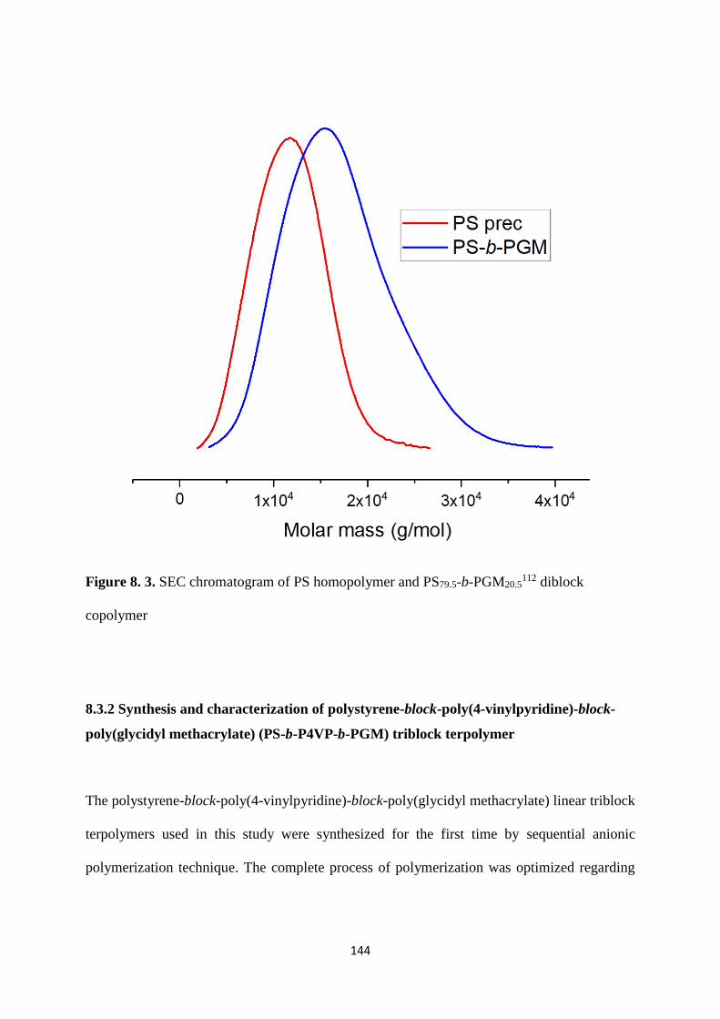
144
Figure 8. 3. SEC chromatogram of PS homopolymer and PS79.5-b-PGM20.5112 diblock
copolymer
8.3.2 Synthesis and characterization of polystyrene-block-poly(4-vinylpyridine)-block-
poly(glycidyl methacrylate) (PS-b-P4VP-b-PGM) triblock terpolymer
The polystyrene-block-poly(4-vinylpyridine)-block-poly(glycidyl methacrylate) linear triblock
terpolymers used in this study were synthesized for the first time by sequential anionic
polymerization technique. The complete process of polymerization was optimized regarding

145
the purification of monomers, initiation of monomers, end capping of carbanion and duration
to complete polymerization.
Figure 8. 4. 1H-NMR spectra of PS-b-P4VP-b-PGM in CDCl3
The first two blocks PS-b-P4VP were synthesized by following the method reported before in
literature [123]. As described earlier in Section 3.1.4 about the reactivity of (glycidyl
methacrylate) (GM) block, the reactivity of PS-b-P4VP macro initiator was reduced by the
addition of 1,1-diphenylethylene (DPE). After half an hour glycidyl methacrylate was added to
the polymer solution and maintained the temperature for 2 h. The polymer solution was
terminated and precipitated in methanol/water solution.

146
The triblock terpolymer characteristics were determined by a combination of size exclusion
chromatography (SEC) and 1H-NMR spectroscopy. Figure 8.4 shows 1H-NMR spectra of PS-
b-P4VP-b-PGM where peaks (c, d, e, f, g) corresponding to the five protons of glycidyl
methacrylate (GM).
The peaks at 8.3 ppm are responsible for the protons of 4-vinylpyridine whereas the rest of the
aromatic protons of styrene, 1,1-diphenylethylene (DPE) and 4-vinylpyridine lies under two
large peaks denoted as (a) in the NMR spectra. The molecular weight distribution of triblock
terpolymer is given in Table 8.3.
Table 8. 3. Characterization data of PS-b-P4VP-b-PGM triblock terpolymer
Batch no. Polymer Mn
(kg/mol)
P4VP
(wt%)
PGM
(wt%)
D
130416 PS-b-P4VP-b-PGM 235 21.5 29.5 1.1

147
Acknowledgement
I would like to express my gratitude to my supervisor Prof. Volker Abetz for providing me the
opportunity to conduct research at the institute of Polymer Research in Helmholtz-Zentrum
Geesthacht. I am grateful for all his insightful discussions and assistance about the research
throughout this project. I am thankful for allowing me to present my work in international
conferences.
I truly appreciate the guidance and support of Dr. Volkan Filiz, my immediate supervisor who
familiarized me with this topic. I truly admire his positive approach and providing a lot of space
to work freely.
I express my heartfelt gratitude to Dr. Sofia Rangou for her valuable input and continuous
interest in my research work.
I would like to thank Clarissa Abetz, Anke Lisa Höhme, Erik Schneider and Evgeni Sperling
for doing microscopic investigations and for all the discussions regarding microscopic analysis
throughout this period. I am greatly thankful to Brigitte Lademann for her tremendous support
in synthesizing the polymers. I am thankful to Silvio Neumann, Thomas Emmler, Maren
Brinkmann and Barbara Bajer for NMR, TGA, DSC, SEC and water flux measurements. I
would like to thank Elvin Aliyev for providing nanosheets to prepare hybrid membranes.
I cordially thank to all my fellow colleagues Dr. Muntazim Munir Khan, Dr. Karabi Halder, Dr.
Kirti Sankhala, Dr. Christian Höhme, David Meis, Jiali Wang and Zhenzhen Zhang.
I am deeply grateful to my brother Ahmed Faraz and my sisters Munnaza, Faiza, Ammara for
their endless love, care, faith and support throughout my life. I would like to thank my uncle
Rehan Aman Ullah for his continuous moral support.
Lastly, I cannot thank my husband enough whose eternal love, support and motivation helped
me turn this whole Ph.D. into a success.
I would like to thank Helmholtz Association for financial support during this whole period of
my Ph.D. research.
I would like to dedicate this thesis to my beloved mother (late) who always encouraged me to
dream big.

148
Curriculum Vitae
Contact details
Address: Querstraße 23, 21502 Geesthacht, Germany
E-mail: [email protected]
Mobile no.: +4915236295158
Education
06/2015 – 10/2019 Ph.D Student
University of Hamburg, Dept. of Physical Chemistry
Grindelallee 117, 20146 Hamburg, Germany
09/2010 - 07/2012 Master of Science
COMSATS University, Dept. of Chemistry Abbottabad,
Pakistan.
09/2008 - 08/2010 Master of Science
Institute of Chemistry, University of the Punjab, Institute of
Chemistry Lahore, Pakistan.
09/2006 - 08/2008 Bachelor of Science
Chemistry with Botany and Zoology, National Science College,
Gujranwala, Pakistan.
Personal information
Date of birth: 23.08.1986
Nationality Pakistani

149
Declaration of Oath
I hereby declare that this thesis on “Integral asymmetric isoporous membrane formation from
novel block copolymers” accommodates the original work of my Ph.D. Several parts of this
dissertation had been published in international peer reviewed journal and therefore, the
similarities with those published work exist. This dissertation is written by me and has not ever
been submitted to any other university or institution to pursue a degree.
Sarah Saleem


![Integral Membrane Proteins (IMPs) - NIST€¦ · Integral Membrane Proteins (IMPs) ... Ellipsometry Data: R’SSR’/[ MES] 2 0 0.5 1 1.5 2 2.5 3 3.5 4 4.5 5 5.5 6 0 10 20 30 40 50](https://static.fdocuments.in/doc/165x107/5af943b57f8b9ae92b8c2693/integral-membrane-proteins-imps-nist-integral-membrane-proteins-imps-.jpg)