Integra Balanced Flue - Cast Tec · Integra Balanced Flue ... (Gas Safe Engineer only) 14 ... This...
16
Integra Balanced Flue Inset Live Fuel Effect Room Sealed Fire Installation and Users Instructions These instructions should be read by the installer before installation and then should be handed to the end user when the installation is complete. This is an official requirement and is the responsibility of the fitter of this appliance. Having installed the appliance, the installer should take the necessary steps to ensure that the user fully understands how to operate the appliance and is also made aware of the fire’s basic cleaning and maintenance requirements.
Transcript of Integra Balanced Flue - Cast Tec · Integra Balanced Flue ... (Gas Safe Engineer only) 14 ... This...

Integra Balanced Flue
Inset Live Fuel Effect Room Sealed Fire
Installation andUsers Instructions
These instructions should be read by theinstaller before installation and then should behanded to the end user when the installationis complete.
This is an official requirement and is theresponsibility of the fitter of thisappliance.
Having installed the appliance, the installershould take the necessary steps to ensurethat the user fully understands how to operatethe appliance and is also made aware of thefire’s basic cleaning and maintenancerequirements.

SECTION PAGE
Notes for the Installer and End User 3
Appliance Data 4
Appliance Dimensions 4
Recess Dimensions 5
Installation Requirements 5
Terminal location 6
Site requirements 8
Ventilation 8
Preparing the Outside Wall 8
Installation Procedure - Standard 22” x 16” 9
Installation Procedure For Decorative Cast Surround 11
Commissioning 11
Modular Coal Layout Instructions 12
Trouble Shooting (Gas Safe Engineer only) 14
Replacement Parts 14
User Instructions 15
Cleaning and Maintenance 16
Guarantee 16
CONTENTS
2

Important notes before installation
This Balanced Flue product is a High Efficiency, Inset Live Fuel Effect appliance. This appliance will generateheat through both radiation and convection, using "room sealed" technology that requires no additionalventilation as it takes combustion air and deposits it's Flue gases outside the house using it's concentric fluesystem. The appliance has been designed to fit various installation situations, as detailed later in theseinstructions.
This appliance has been designed, tested and manufactured to BS EN 613: 2001 +A1: 2003 + C1: 2008 relatingto Balanced Flue Appliances and must be installed by a qualified Gas Safe Registered Installer in accordancewith the Gas Safety (installation and use) regulations 1994 and all other relevant standards.
This fire is a very effective heating appliance and must be fitted against a wall of non-combustible material asclassified in BS 476-4:1970 (2007)
The installation must be undertaken by a competent person in accordance with Gas Safety (Installation and Use)Regulations 1998. The person should be on the Gas Safe Register which is the official list of gas engineers whoare qualified to work safely and legally on gas appliances and are approved by the HSE under the aboveregulations. The installation must adhere to the requirements of the local and national Building regulations andnational standards. These instructions are to be fully read before commencing the installation and theinformation must be followed. After installation they must be left with the user for reference and safekeeping.This appliance must be installed in accordance with the rules in force and only used in a sufficiency ventilatedspace. No additional ventilation is required, as the appliance does not use air from the room for combustion oroperation of the Flue. However an adequate supply of fresh air to maintain temperatures within limits and acomfortable living environment is advised. This appliance is factory set for operation on the gas type andpressure as stated on the appliance data plate. No other gas or pressure should be used. Before installation,check that the local distribution conditions, nature of gas and pressure, and adjustment of the appliance arecompatible. The appliance is intended for use on a gas installation with a governed meter. Ensure that the FlueTerminal is not in any way obstructed and is clear of vegetation, i.e. trees, shrubs etc. and that no objects areleant against the terminal or guard. Only flue components approved by Legend Fires for this appliance may beused.
WARNING: Do not operate this appliance if the glass panel is broken (or cracked), removed or is open.Always clean the window panel before the fire is ignited. Any finger prints must be removed, as these will beburnt into the glass and will be un-removable.
This appliance is designed as a heating appliance, and as such will get very hot in operation, all surfaces(except the controls and access door) are considered to be working surfaces and as such not be touched. Thefront window and surround are not considered to be fully secure guards against accidental contact. It isrecommended that an approved fire screen be used if children, the elderly or persons with limited mobility are tobe present in the same area. Do not place curtains, laundry, furniture etc. within a safe distance of 600mm of thisappliance. Do not attempt to burn rubbish on this appliance.
If this appliance is extinguished, on purpose or other, no attempt to relight should be made within 3minutes.
NOTES FOR THE INSTALLER AND END USER
3

Gas Type and Category G20 Natural Gas Cat: I2H
Inlet Pressure 20 mbar
Max. Energy Input Gross 4.5 kW Nett 4.1 kW
Max. Gas Rate 0.43 m3/hr
Min. Energy Input Gross 1.5 kW Nett 1.4 kW
Min. Gas Rate 0.14 m3/hr
Burner Pressure (Hot) High 17.6 (±0.5) mbar Low 2.2 mbar
Efficiency Class 1
NOx Class 5
Injector Marking 280 Stereomatic [elbow]
Gas Inlet Connection 8mm
Ignition Piezo Spark
Spark Gap 3mm (±1.0mm)
Country of Destination (use) AT, CH, CY, CZ, DK, EE, ES, FI, GB, GR, HR, IE, IT,
LT, LV, NO, PT, RO, SE, Sl, SK, TR
APPLIANCE DATA
4
APPLIANCE DIMENSIONS
Fig. 1
150mm
450mm535mm
550mm616mm
195mm
519mm
400mm
258mm

This appliance has been designed to fit into two main categories of installation. The first is to fit into an openingcreated in the inner leaf of an external wall or secondly into a false chimney breast or extended fire surroundbuilt to conceal the appliance. The appliance can also be fitted into an unserviceable or inoperative fireplaceserved by a disused natural draught flue, provided that the requirements for terminal location and flue length canstill be successfully met. It is recommended that the old flue be sealed off. The Flue pipe must be able to passright through the outside wall to duct fresh air in to the appliance and exhaust gasses out correctly. The Flueterminal must be screwed to the outside wall, with both of the pipes of the flue fitting onto the spigot on the fire.
The appliance is to be installed onto a suitable non-combustible surface at least 12mm thick, which must coverthe entire base area of the box. The appliance must be installed with a fire surround and or back panel setcapable of withstanding 180°C. Any combustible materials directly behind the fire frame (or back panel) andclose to the appliance must be removed and replaced with noncombustible material such as cement, browning,"Superlux" board or equivalent materials.
The standard flue terminal length is 450mm, however this may be cut down using either tin snips or a grinder toa minimum length of 100mm.
The Flue terminal requires adequate clearance from other buildings, openings and obstructions to operatecorrectly and safely. Please refer to the Terminal Locations section. Terminals exhausting in passageways, overfootpaths etc. may be subject to local bye-laws, and must not create a nuisance. If in doubt contact your localcouncil for further advice. In some instances it may be necessary to fit a safety cage to ensure no problemsarise. Avoid locating the terminal outlet close to combustible materials e.g. drain pipes, fences etc. if it isunavoidable, a metal deflector must be used if the object is significantly heated. Covered areas such as car portsor covered walkways should be avoided, but if necessary, the following guidance may be used; the covered areashould have at least two open sides (i.e. it comprises roof and maximum one supporting wall). If more than onewall is filled, advice should be sought from Gas Safe on locations suitability. For minimum clearances see theterminal location section. Particular care should be taken with plastic roofs, if in any doubt the minimumdistance stated should be to the lowest part of the roof.
As with any flue outlet, some discoloration of the wall around the terminal may occur with light coloured walls.Always avoid locating the terminal in conspicuous positions on light walls. Terminal location guidance is given inthe next section but as a general rule avoid ledges, drain pipes, projections etc. The prevailing wind conditionscombined with such objects can combine to produce unexpected conditions around the terminal.
RECESS DIMENSIONS
5
INSTALLATION REQUIREMENTS
A - Opening Width min. 410mm max. 450mm
B - Opening Height min. 560mm max. 583mm
C - Recess Depth min 200mm

TERMINAL LOCATION
6
Dimension Terminal Position Minimum
A* Directly below an opening, air brick, window etc. 600mmB Directly above an opening, air brick, window etc. 300mmC Horizontally to an opening, air brick, window etc. 400mmD Below gutters, soil pipes or drain pipes 300mmE Below eaves 300mmF Below balconies or car port roof 600mmG From a vertical drain or soil pipe 300mmH From an internal or external corner or to a boundary
alongside the terminal 600mmI Above ground, roof or balcony level 300mmJ From a surface or boundary facing the terminal 600mmK From another terminal facing the terminal 600mmL From an opening in a car port 1200mmM Vertically from another terminal on the same wall 1500mmN Horizontally from another terminal on the same wall 300mm
* I addition, the terminal should not be nearer than 300mm to an opening in the building fabric formed for thepurpose of accommodating a built in element such as a window frame.
A
M
A
NHH
K
C
G
H
J
FL
I
I
DEB
Fig. 2
Fig. 3
Fig. 4
Boundary
Building
Building
Opening intobuilding
Terminal
600mm
2m
Boundary
Terminal
300mm
Building
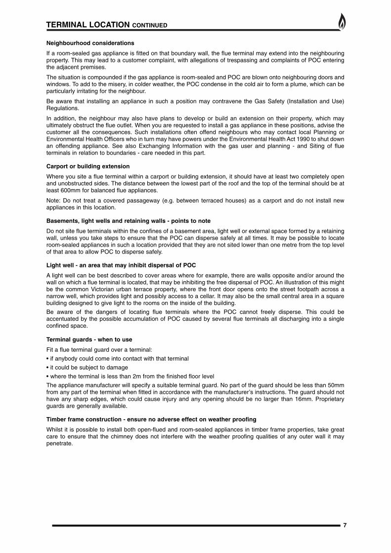
Neighbourhood considerations
If a room-sealed gas appliance is fitted on that boundary wall, the flue terminal may extend into the neighbouringproperty. This may lead to a customer complaint, with allegations of trespassing and complaints of POC enteringthe adjacent premises.
The situation is compounded if the gas appliance is room-sealed and POC are blown onto neighbouring doors andwindows. To add to the misery, in colder weather, the POC condense in the cold air to form a plume, which can beparticularly irritating for the neighbour.
Be aware that installing an appliance in such a position may contravene the Gas Safety (Installation and Use)Regulations.
In addition, the neighbour may also have plans to develop or build an extension on their property, which mayultimately obstruct the flue outlet. When you are requested to install a gas appliance in these positions, advise thecustomer all the consequences. Such installations often offend neighbours who may contact local Planning orEnvironmental Health Officers who in turn may have powers under the Environmental Health Act 1990 to shut downan offending appliance. See also Exchanging Information with the gas user and planning - and Siting of flueterminals in relation to boundaries - care needed in this part.
Carport or building extension
Where you site a flue terminal within a carport or building extension, it should have at least two completely openand unobstructed sides. The distance between the lowest part of the roof and the top of the terminal should be atleast 600mm for balanced flue appliances.
Note: Do not treat a covered passageway (e.g. between terraced houses) as a carport and do not install newappliances in this location.
Basements, light wells and retaining walls - points to note
Do not site flue terminals within the confines of a basement area, light well or external space formed by a retainingwall, unless you take steps to ensure that the POC can disperse safely at all times. It may be possible to locateroom-sealed appliances in such a location provided that they are not sited lower than one metre from the top levelof that area to allow POC to disperse safely.
Light well - an area that may inhibit dispersal of POC
A light well can be best described to cover areas where for example, there are walls opposite and/or around thewall on which a flue terminal is located, that may be inhibiting the free dispersal of POC. An illustration of this mightbe the common Victorian urban terrace property, where the front door opens onto the street footpath across anarrow well, which provides light and possibly access to a cellar. It may also be the small central area in a squarebuilding designed to give light to the rooms on the inside of the building.
Be aware of the dangers of locating flue terminals where the POC cannot freely disperse. This could beaccentuated by the possible accumulation of POC caused by several flue terminals all discharging into a singleconfined space.
Terminal guards - when to use
Fit a flue terminal guard over a terminal:
• if anybody could come into contact with that terminal
• it could be subject to damage
• where the terminal is less than 2m from the finished floor level
The appliance manufacturer will specify a suitable terminal guard. No part of the guard should be less than 50mmfrom any part of the terminal when fitted in accordance with the manufacturer’s instructions. The guard should nothave any sharp edges, which could cause injury and any opening should be no larger than 16mm. Proprietaryguards are generally available.
Timber frame construction - ensure no adverse effect on weather proofing
Whilst it is possible to install both open-flued and room-sealed appliances in timber frame properties, take greatcare to ensure that the chimney does not interfere with the weather proofing qualities of any outer wall it maypenetrate.
TERMINAL LOCATION CONTINUED
7

SITE REQUIREMENTS
8
This appliance may be installed by any of the following methods:
1. Fitting against the inside face of an external wall. A false chimney breast can then be suitably constructed or arebated fire surround fitted to enclose the depth of the fire. If the false chimney is to be of a woodenconstruction, then clearances and insulation must be as for a timber constructed wall.
2. An opening in the inner leaf of a cavity wall may be constructed for insertion of the appliance. Bridging thecavity may cause unwanted moisture to track to the inside of the house from the cavity. Protection from moistureand falling debris above the cavity box should be provided. If in doubt, consult local building local building controlofficers. The appliance can also be fitted into an unserviceable or inoperative fireplace served by a disusednatural draught flue, provided that the requirements for terminal location and flue length can still be successfullymet. It is recommended that the old flue be sealed off.
3. Fitting into a timber framed house wall using clearances and insulation as described in the appropriatesection. If in doubt, consult local building control officers.
The opening dimensions for insetting the appliance must be; WIDTH 410mm min. 450mm max, HEIGHT 570mmmin 600mm max. The opening must be these sizes for the full depth of the cavity. Opening DEPTH must be200mm minimum, this includes any plaster, cement or infill/back panels that form part on the installation.If a concealed gas connection is to be made, the supply pipe should always be sleeved through walls and floorsusing the shortest possible route. It is possible to install the gas supply from the side of the hearth and round intothe cavity, but use only factory sleeved pipe. No more than 1.5m of Ø8mm pipe must be used to avoidunnecessary pressure drops.
The wall for the opening must be non-combustible or prepared as described in the relevant section. Bareplasterboard must be protected by non-combustible plaster or replaced with "Superlux" board, or othercompatible material. Any gap between wall boards and the wall must be filled using glass fibre insulation, siliconmastic or similar method to prevent heat ingress. If the appliance is to be installed as a "hole in the wall"installation, it does not require any hearth as such, provided that the incandescent flame of the fire bed is atleast 300mm above the floor level. If fitting the fire without a hearth, consideration should be given to theincreased safety risk. The installer should inform the user of potential safety issues, including not placingcombustible material directly in front of the appliance (floor covering such as carpet etc. is OK). The installershould use his judgement where necessary to advise against a hearthless installation. NOTE: it may benecessary to install a ledge for placement of the fire front, for this type of installation.
The appliance requires a hearth with non-combustible surface of at least 12mm thickness, projecting100mmfrom the front of the appliance. The Top surface must be at least 50mm above the surrounding floor level, or besurrounded by a raised edge or fender 50mm high. Any type of fire surround used with this appliance must beadequately sealed to the wall and floor to prevent excess draughts from around the back of the appliance.
A combustible shelf may be fixed to the wall above the appliance, provided it has a maximum depth of 180mmand is 850mm from the hearth. The Shelf depth may be increased, however the shelf height must increased by25mm for every 12.5mm of shelf depth (i.e. a ratio of 2:1). Combustible materials, such as wood, may be fitted towithin100mm of either side of the fire frame/trim, provided the forward projection does not exceed 100mm. Anycombustible side walls must be at least 500mm to the side of the radiant heat source.
As with all heating appliances, any decorations, soft furnishings, and all coverings (i.e. wallpapers)positioned too close to the appliance may discolour or scorch.
VENTILATION
PREPARING THE OUTSIDE WALL
No additional ventilation is required, as the appliance does not use air from the room for combustion or operationof the Flue. However an adequate supply of fresh air to maintain temperatures within limits and a comfortableliving environment can be beneficial.
For Republic of Ireland, see relevant rules in force.
From inside the house, firstly find the FINISHED HEARTH LEVEL, including any decorative hearth that will be inplace when the fire is in position. This is the reference plane to which you should work. Mark the verticalcentreline of the fireplace on the wall. Next, mark the centre of the flue pipe hole. This is 450 mm from theFINISHED HEARTH LEVEL. Pilot through the wall to ascertain the outside finished flue centre line. If necessary,check locations of wires and pipes in the wall first.
Check the outside flue terminal location using the pilot hole as a guide. Make any adjustments to the fire locationor the surroundings as required to comply with terminal siting. Finally, core drill through the outside wall with a155mm (6") core drill to provide the location for the outside part of the flue. If a core drill is not available, mark a155mm diameter circle and stitch drill or chisel out the required area of brick. Clear rubble from the cavity andclear back any insulation material.

9
1. Carefully lift the appliance out of the packaging taking care not to damage the ceramic components in the separate carton.
2. Remove the magnetic trim and store to one side to prevent any damage.
3. Remove the louvered panel by lifting up and pulling forwards.
4. Slacken the five machine screws on the top retaining strip.
5. Unscrew the two securing screws from the lower infill panel and remove the panel. Tilt the glass forwards and slide out.
6. Cut the foam sealing strip (in plastic bag supplied) to length and stick a continuous strip down the two sides and across the top of the radiant box. When the box is placed against a flat surface the foam strip will form a seal around the boxes flange.
7. Carefully lift the appliance into position in the fireplace opening and check that the flange of the radiant box fits flush against the sealing face with no gaps present.
8. Measure from the inside wall surface to the outside wall face, this is Dimension X. Subtract 170mm from Dimension X to calculate the finished flue length. Mark the finished flue length onto the larger tube, measuring from the terminal end.
9. Mark out four of the fixing holes. Remove the box and carefully drill and fit “Rawl” plugs or see alternative fixing page 10.
10. Using tin snips or a fine cutting disc, cut through both flue tubes (the two tubes can be split by removing the machine screw). Secure the flue to the rear of the fire box using the clamp provided.
11. Decide which opening of the appliance the gas supply will be entering the radiant box and remove therelevant blanking plate. Feed the 8mm gas supply pipe through the opening from the rear of the fire and re-fit theblanking plate around the supply pipe.
12. Slide the fire and flue into the fireplace opening ensuring the flue locates into the hole in the brickwork.Ensure that the larger flue tube extends 25mm beyond the outer wall face when the fire is fully inserted into theopening and that the machine screw is located at the top of the larger flue.
13. Secure the box into place using four screws (straight shank screws are recommended for marble).
14. From outside, fit the cover plate over the large flue tube and secure with the two screws provided.
INSTALLATION PROCEDURE FOR STANDARD 22” X 16” OPENING
Fig. 5
Infill panel securingscrews (x 2)
Trim
LouvredPanel
MachineScrews (x 5)
X
X-170mm
25mm
Machine Screw
Fig. 6

10
ALTERNATIVE FIXING METHOD
Where the drilling of the back panel is not practical, an alternative fixing method may be employed using the optional cable fixingkit provided. Drill four holes in the rear of the fireplace opening.Securely fix the four eye bolts provided using suitable Rawlplugs. Feed one cable through each of the eyes in the rear ofthe fire box.Fix the box into the opening, securing into position using thecable fixing kit. Do not cut off the loose ends as the full lengthis required should the box need refitting at any time. Coil upand securely store underneath the burner tray.
INSTALLATION PROCEDURE FOR STANDARD 22” X 16” OPENING CONTINUED
Radiant box
Hearth
Eye Bolts
Tension Nut
Cable Clamping Screw
Fig. 7
Insert cables through two smallholes in vertical edge of top plate.
119mm
Centre Line
567mmmax
Fig. 8
Drill holes for 4 eye bolts betweenmax and min heights.

INSTALLATION PROCEDURE FOR DECORATIVE CAST SURROUND
11
COMMISSIONING
1. With the fire box installed in the opening, determine the length of 8mm gas supply needed and cut to length.
2. Before making the final connection, thoroughly purge the supply pipe to clear any foreign matter, i.e. masonrydust etc, as this could lead to blockages in the control valve and/or pilot assemblies.
3. Make the gas connection and carry out a gas soundness test.
4. Unscrew the inlet pressure test point sealing screw and fit a manometer. Ignite the appliance and turn to thehigh position.
5. Take a pressure reading and consult the technical data (page 4) to establish the correct working pressure.
6. Once the pressure has been checked and verified, turn off the appliance. Consult the ceramic component setup diagrams and fit the ceramics as per the instructions.
7. Re-install glass panel. The glass should be positioned centrally to ensure the decorative trim will fit over it.
1. Install the decorative cast surround into the fireplace opening and ensure it is fully sealed including the openarea above the fire (see Fig. 7).
2. Carefully lift the fire box out of the packaging taking care not to damage the ceramic components in theseparate carton.
3. Cut the foam sealing strip (in plastic bag supplied) to length and stick a continuous strip up one side, acrossthe top and down the other side of the rear of the radiant box. When the box is placed against the cast surroundthe foam strip will form a seal around the boxes flange.
4. Lift the fire box on to the two studs at the top of the surround and check that the flange of the radiant box fits flush against the sealing face with no gaps present.
5. Locate the decorative frame on to the studs and secure with the two nuts provided.
6. Insert the two screws into the lower holes in the decorative frame and carefully tighten ensuring the fire box is securely clamped between the frame and the surround.
Fig. 7
Decorative CastSurround
SecuringStuds
Securing Screws
Decorative Frame
ENSURE THIS AREAIS SEALED
Foam Sealing Strip
MODULAR COAL LAYOUT INSTRUCTIONS
12
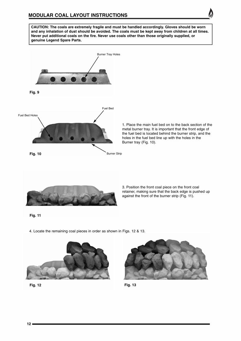
1. Place the main fuel bed on to the back section of themetal burner tray. It is important that the front edge ofthe fuel bed is located behind the burner strip, and theholes in the fuel bed line up with the holes in theBurner tray (Fig. 10).
3. Position the front coal piece on the front coalretainer, making sure that the back edge is pushed upagainst the front of the burner strip (Fig. 11).
CAUTION: The coals are extremely fragile and must be handled accordingly. Gloves should be wornand any inhalation of dust should be avoided. The coals must be kept away from children at all times.Never put additional coals on the fire. Never use coals other than those originally supplied, orgenuine Legend Spare Parts.
Fig. 9
Fig. 10
Fig. 12 Fig. 13
Fig. 11
Burner Strip
Burner Tray Holes
Fuel Bed Holes
Fuel Bed
4. Locate the remaining coal pieces in order as shown in Figs. 12 & 13.
MODULAR COAL LAYOUT INSTRUCTIONS CONTINUED
13
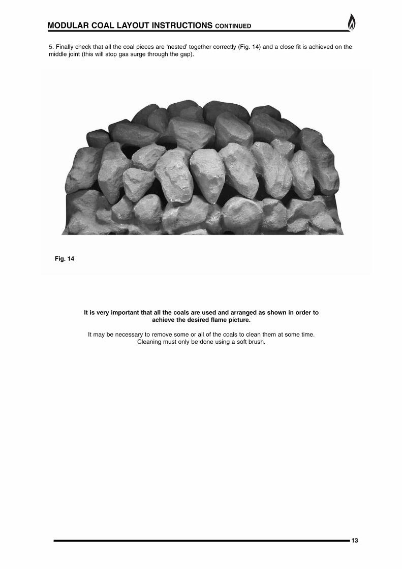
Fig. 14
It is very important that all the coals are used and arranged as shown in order to achieve the desired flame picture.
It may be necessary to remove some or all of the coals to clean them at some time. Cleaning must only be done using a soft brush.
5. Finally check that all the coal pieces are ‘nested’ together correctly (Fig. 14) and a close fit is achieved on themiddle joint (this will stop gas surge through the gap).

1. The Piezo will not spark.Check: If the electrode is cracked or broken - Replace pilot assembly.If the HT lead is shorting out on the burner body - Locate where the short is occurring, isolate and/or re-route thelead.If the HT unit/lead is faulty - Replace as necessary.
2. The Pilot will not light (but the Piezo is sparking).Check: If the gas is reaching the pilot - check joints and connections.If the pilot jet is blocked - Inspect and clean.If the pilot is still not passing gas - Replace the pilot assembly.
3. The Pilot lights but goes out when the control knob is released.Check: If the Thermocouple is loose or disconnected at the control valve - remake the connection.If the Thermocouple is faulty - Replace.If the Electro magnetic valve is faulty - replace valve.
4. The Burner will not light readily from the pilot.Check: If the coals are obstructing the pilot to burner path i.e. Are the coals blocking the opportunity for the pilotto light the burner - Relay the coal set as per Ceramic Component Layout Instructions.
5. The fire makes a roaring noise when lit.Check: That the front coal is seated correctly and the pilot hole is positioned correctly over the pilot assembly.
IF ANY PART OF THE PILOT ASSEMBLY IS SUSPECTED AS BEING FAULTY THECOMPONENT MUST BE REPLACED.
6. The flames appear blue (after the fire has fully warmed up). The coals/ceramic liners have soot deposits.Check: That the coals have not moved from the original setting - Relay the coals as per the Ceramic ComponentLayout Instructions.The Flue terminal may be blocked. If so take steps to rectify.
7. The flame picture is low on the high setting.Check: For any partial blockages - Check all obvious locations for debris in pipe work and fittings. Inlet gaspressure, both standing and working gas pressure - Identify problem and take necessary steps to rectify.
Note: Flame pattern improves with use.
TROUBLE SHOOTING (GAS SAFE ENGINEER ONLY)
14
REPLACEMENT PARTS
1. Front Coal, Fuel Bed and Top Sections - All these ceramic components can be replaced at service intervalsdepending on their condition. If the coals do require replacement, the consumer can do so provided that theCeramic Component Layout Instructions are adhered to. Only genuine Legend replacement parts should beused. (Order Ref: Front Coal: EBFFC02 Fuel Bed: EBFM03 Top Sections: EBFTS04)
2. Pilot Assembly - In the unlikely event of a pilot failure, the pilot assembly should only be replaced by a Gas Safe Registered Engineer. The user must not carry out this work. (Order Ref: LEG226)
3. Control Tap - In the unlikely event of control tap failure, the assembly should only be replaced by a Gas Safe Registered Engineer. The user must not carry out this work. (Order Ref: LEG60)
4. Main Injector - In the unlikely event of main injector failure, the fitting should only be replaced by a Gas Safe Registered Engineer. The user must not carry out this work. (Order Ref: LEG280)
5. Glass Panel - Should the glass become cracked or broken, the fire should not be used under anycircumstance. (Order Ref: LEG281)
6. Glass Rope Seal - The integrity of the glass rope seal should be checked on service and replaced ifnecessary by a Gas Safe Registered Engineer (Order Ref: LEG224)
7. Plastic Coated Mild Steel Terminal Guard (Order Ref: LEG286)
8. Stainless Steel Terminal Guard (Order Ref: LEG287)

USER INSTRUCTIONS
15
Please also familiarise yourself with the Notes for the Installer and End User on page 3.Never place combustible material directly in front of this appliance. Floor covering such as carpet is acceptablebut must be a minimum of 300mm from the incandescent flame. Any combustible shelf must be at least 215mmabove the fire trim, providing the shelf depth is 150mm or less.
OPERATION AND CONTROLSIt is most important that the operator of this gas appliance has fully read and understood all the operating,cleaning and maintenance procedures as laid out in these instructions.
Lighting Procedure
1. To light the fire, remove the ash pan cover.
2. Control knob to be in POSITION 1 at commencement of the ignition sequence.
3. Fully depress control knob and turn anticlockwise to POSITION 2 where it reaches a natural restriction (allowa couple of seconds for the pilot gas to purge through the pipe). A sparking click is heard/felt and the pilot flameis then lit (the fire can safely be left on permanent pilot at this stage for future lighting if preferred or can beignited every time the fire is lit). The pilot assembly is located at the front lefthand side of the fire, and whenignited (this can take two or three ‘clicks’) it can be seen through the front coal set. Keep the knob depressed for10/15 seconds to allow the thermocouple to establish the pilot flame. The knob can then be released.
4. The operating level of the burner is now set by turning the control knob from the pilot POSITION 2 through theminimum setting POSITION 3 to the maximum POSITION 4. The control knob is adjustable between these twopositions.
5. To turn off the appliance, depress the control knob and turn clockwise until the POSITION 2 is reached. Themain burner will go out but the pilot light will still be lit. The pilot can then be extinguished by depressing thecontrol knob and then turning to the off POSITION 1.
In the event of failure of the normal means of ignition, Fully depress control knob and turn anticlockwise toPOSITION 2 and light the pilot with a naked flame from beneath the burner tray.
The fire is a very efficient heating appliance and therefore care must be taken not to touch working surfacesincluding the glass when operating. This particularly applies around the perifery of the glass and louvre outlet.Other areas considered to be working surfaces are everything except the control handles and fret knob.
WARNINGS:
Any alteration to this appliance including its ceramic components may render it inoperable andunsafe.
ALWAYS run this appliance on the high setting for the first 30 minutes (minimum) - Failure to do thismay result in poor combustion and excessive sooting.
Never use this appliance if the glass panel is broken, removed or is open.
Fig. 15
POSITION 1OFF
POSITION 2IGNITION/PILOT
POSITION 3MINIMUM SETTING
POSITION 4MAXIMUM SETTING

CLEANING AND MAINTENANCE
Cast Tec recommend that this appliance is serviced at regular 12 monthly intervals. The flue should also bechecked regularly to ensure that all products of combustion are entering the flue and there is no excessive buildup of soot.
It is the user’s responsibility to ensure that the appliance is kept in a clean serviceable condition.
To remove the glass
1. Remove the magnetic trim and store to one side to prevent any damage.
2. Remove the louvered panel by lifting up and pulling forwards.
3. Slacken the five machine screws on the top retaining strip.
4. Unscrew the two securing screws from the lower infill panel and remove the panel. Tilt the glass forwards andslide out.
5. Clean the glass with a damp cloth. For stubborn stains use a proprietary cream cleaner or ceramic hobcleaner.
Ceramic Components and Fuel BedDebris from any source should be removed with a soft brush.Please ensure that any debris including soot deposits are removed from the appliance and not left on the fuelbed.It is recommended that the user should, on a regular quarterly basis, carefully remove all ceramic componentsand thoroughly clean the stainless steel burner strip and the pilot assembly. Any build up of debris in this areacould affect the operation of the appliance.NOTE: It is common to find surface cracks in the ceramic components. This is due to the expansion andcontraction of the ceramic fibres caused by the intense heat that the burner generates. The cracks will not affectthe safe operation of this appliance. However, great care must be taken when handling the ceramic componentsas they will break if handled incorrectly. Do not use a vacuum cleaner to clean the ceramics.
Ceramic Liners - Use only a soft brush to remove any soot deposits from the ceramic liners during cleaning asthis is the only method that can be used to remove deposits. The ceramic liners are very delicate and should betreated accordingly.
6. Reassemble in reverse order. The screws should be tightened enough to ensure the glass is sealed. Theglass should be positioned centrally to ensure the decorative trim will fit over it.
Trims and Frets - The trim and fret should be removed from the appliance for cleaning, please ensure that theappliance has cooled thoroughly. Metal trims and frets maybe lacquer coated and Atherefore do not requirepolishing.
Your appliance is guaranteed for one year from proof of purchase. Should the appliance prove defective withinthat period we agree to repair or replace (at our discretion) the component or appliance provided that:
1. The user can produce a receipt for proof of purchase/installation.2. The appliance has been supplied by an authorised stockist and has been installed by a qualified installer, allinstallation and operating instructions have been strictly adhered to.3. No alterations have been carried out on the appliance or component parts without our written consent.4. The appliance has not been used for any purpose other than those intended.5. The appliance has not been damaged accidentally or due to fair wear and tear.
Guarantee claims should be made through your appliance supplier. The Guarantee is restricted to UKMainland and is additional to your statutory rights.
GUARANTEE
Unit 404 Glenfield Park Business Centre Blakewater Road Blackburn Lancashire BB1 5QH
Tel: 01254 695244 Fax: 01254 695255 Web: www.legend-fires.com Email: [email protected]
Issue 2 - 22/11/12