
Integer Arithmetic Megafunctions User Guide
159
Integer Arithmetic Megafunctions User Guide 101 Innovation Drive San Jose, CA 95134 www.altera.com UG-01063 2013.06.10 Subscribe Feedback
Transcript of Integer Arithmetic Megafunctions User Guide

Integer Arithmetic Megafunctions UserGuide
101 Innovation DriveSan Jose, CA 95134www.altera.com
UG-010632013.06.10
Subscribe
Feedback
Contents
Integer Arithmetic Megafunctions.....................................................................1-1Device Family Support................................................................................................................................1-2Design Flow..................................................................................................................................................1-2Design Example Files...................................................................................................................................1-2
LPM_ADD_SUB (Adder/Subtractor).................................................................2-1Features.........................................................................................................................................................2-1Resource Utilization and Performance.....................................................................................................2-1Verilog HDL Prototype...............................................................................................................................2-2VHDL Component Declaration................................................................................................................2-3VHDL LIBRARY_USE Declaration..........................................................................................................2-3Ports...............................................................................................................................................................2-3Parameters.....................................................................................................................................................2-4
LPM_COMPARE (Comparator).........................................................................3-1Features.........................................................................................................................................................3-1Resource Utilization and Performance.....................................................................................................3-2Verilog HDL Prototype...............................................................................................................................3-2VHDL Component Declaration................................................................................................................3-3VHDL LIBRARY_USE Declaration..........................................................................................................3-3Ports...............................................................................................................................................................3-3Parameters.....................................................................................................................................................3-4
LPM_COUNTER (Counter)................................................................................4-1Features.........................................................................................................................................................4-1Resource Utilization and Performance.....................................................................................................4-2Verilog HDL Prototype...............................................................................................................................4-2VHDL Component Declaration................................................................................................................4-3VHDL LIBRARY_USE Declaration..........................................................................................................4-3Ports...............................................................................................................................................................4-3Parameters.....................................................................................................................................................4-5
Altera Corporation
TOC-2

LPM_DIVIDE (Divider)......................................................................................5-1Features.........................................................................................................................................................5-1Resource Utilization and Performance.....................................................................................................5-1Verilog HDL Prototype...............................................................................................................................5-2VHDL Component Declaration................................................................................................................5-2VHDL LIBRARY_USE Declaration..........................................................................................................5-3Ports...............................................................................................................................................................5-3Parameters.....................................................................................................................................................5-4
LPM_MULT (Multiplier)....................................................................................6-1Features.........................................................................................................................................................6-1Resource Utilization and Performance.....................................................................................................6-1Verilog HDL Prototype...............................................................................................................................6-2VHDL Component Declaration................................................................................................................6-3VHDL LIBRARY_USE Declaration..........................................................................................................6-3Ports...............................................................................................................................................................6-3Parameters.....................................................................................................................................................6-4
ALTECC (Error Correction Code: Encoder/Decoder).......................................7-1ALTECC_ENCODER Features..................................................................................................................7-2Resource Utilization and Performance.....................................................................................................7-3Verilog HDL Prototype (ALTECC_ENCODER)....................................................................................7-4Verilog HDL Prototype (ALTECC_DECODER)....................................................................................7-5VHDL Component Declaration (ALTECC_ENCODER).....................................................................7-5VHDL Component Declaration (ALTECC_DECODER).....................................................................7-6VHDL LIBRARY_USE Declaration..........................................................................................................7-6Ports (ALTECC_ENCODER)....................................................................................................................7-6Ports (ALTECC_DECODER)....................................................................................................................7-7Parameters (ALTECC_ENCODER)..........................................................................................................7-7Parameters (ALTECC_DECODER)..........................................................................................................7-8Design Example 1: ALTECC_ENCODER................................................................................................7-8
Understanding the Simulation Results.........................................................................................7-9Design Example 2: ALTECC_DECODER..............................................................................................7-12
Understanding the Simulation Results.......................................................................................7-13
ALTERA_MULT_ADD (Multiply-Adder).........................................................8-1
Altera Corporation
TOC-3
Features.........................................................................................................................................................8-2Pre-adder...........................................................................................................................................8-3Systolic Delay Register.....................................................................................................................8-5Pre-load Constant............................................................................................................................8-9Double Accumulator.......................................................................................................................8-9
Verilog HDL Prototype.............................................................................................................................8-10VHDL Component Declaration..............................................................................................................8-10VHDL LIBRARY_USE Declaration........................................................................................................8-10Ports.............................................................................................................................................................8-10Parameters..................................................................................................................................................8-12Design Example: Implementing a Simple Finite Impulse Response (FIR) Filter.............................8-17Understanding the Simulation Results...................................................................................................8-18
ALTMEMMULT (Memory-based Constant Coefficient Multiplier).................9-1Features.........................................................................................................................................................9-1Resource Utilization and Performance.....................................................................................................9-2Verilog HDL Prototype...............................................................................................................................9-2VHDL Component Declaration................................................................................................................9-3Ports...............................................................................................................................................................9-3Parameters.....................................................................................................................................................9-4Design Example: 8 × 8 Multiplier..............................................................................................................9-5Understanding the Simulation Results.....................................................................................................9-6
ALTMULT_ACCUM (Multiply-Accumulate)..................................................10-1Features.......................................................................................................................................................10-2Resource Utilization and Performance...................................................................................................10-2Verilog HDL Prototype.............................................................................................................................10-4VHDL Component Declaration..............................................................................................................10-4VHDL LIBRARY_USE Declaration........................................................................................................10-4Ports.............................................................................................................................................................10-4Parameters..................................................................................................................................................10-6Design Example: Shift Accumulator.....................................................................................................10-16Understanding the Simulation Results.................................................................................................10-17
ALTMULT_ADD (Multiply-Adder).................................................................11-1Features.......................................................................................................................................................11-3
Pre-adder.........................................................................................................................................11-4
Altera Corporation
TOC-4

Systolic Delay Register...................................................................................................................11-6Pre-load Constant........................................................................................................................11-10Double Accumulator...................................................................................................................11-10
Resource Utilization and Performance.................................................................................................11-11Verilog HDL Prototype...........................................................................................................................11-11VHDL Component Declaration............................................................................................................11-11VHDL LIBRARY_USE Declaration......................................................................................................11-12Ports...........................................................................................................................................................11-12Parameters................................................................................................................................................11-14Design Example: Implementing a Simple Finite Impulse Response (FIR) Filter...........................11-40Understanding the Simulation Results.................................................................................................11-41
ALTMULT_COMPLEX (Complex Multiplier)................................................12-1Complex Multiplication............................................................................................................................12-2Canonical Representation.........................................................................................................................12-2Conventional Representation...................................................................................................................12-3Features.......................................................................................................................................................12-3Resource Utilization and Performance...................................................................................................12-4Verilog HDL Prototype.............................................................................................................................12-4VHDL Component Declaration..............................................................................................................12-5VHDL LIBRARY_USE Declaration........................................................................................................12-6Ports.............................................................................................................................................................12-6Parameters..................................................................................................................................................12-6Design Example: Multiplication of 8-bit Complex Numbers Using Canonical
Representation......................................................................................................................................12-8Understanding the Simulation Results...................................................................................................12-8
ALTSQRT (Integer Square Root).....................................................................13-1Features.......................................................................................................................................................13-1Resource Utilization and Performance...................................................................................................13-1Verilog HDL Prototype.............................................................................................................................13-2VHDL Component Declaration..............................................................................................................13-2VHDL LIBRARY_USE Declaration........................................................................................................13-3Ports.............................................................................................................................................................13-3Parameters..................................................................................................................................................13-4Design Example: 9-bit Square Root.........................................................................................................13-4Understanding the Simulation Results...................................................................................................13-4
Altera Corporation
TOC-5
PARALLEL_ADD (Parallel Adder)..................................................................14-1Feature.........................................................................................................................................................14-1Resource Utilization and Performance...................................................................................................14-1Verilog HDL Prototype.............................................................................................................................14-2VHDL Component Declaration..............................................................................................................14-3VHDL LIBRARY_USE Declaration........................................................................................................14-3Ports.............................................................................................................................................................14-3Parameters..................................................................................................................................................14-4Design Example: Shift Accumulator.......................................................................................................14-5Understanding the Simulation Results...................................................................................................14-5
Document Revision History..............................................................................15-1
Altera Corporation
TOC-6

1Integer Arithmetic Megafunctions
2013.06.10UG-01063 Subscribe Feedback
The Altera® integer arithmetic megafunctions offer you the convenience of performing mathematicaloperations on FPGAs through parameterizable functions that are optimized for Altera device architectures.These functions offer efficient logic synthesis and device implementation. You can customize themegafunctions by configuring various parameters to accommodate your needs.
Altera integer arithmetic megafunctions are divided into the following two categories:
• Library of parameterized modules (LPM) megafunctions• Altera-specific (ALT) megafunctions
The following table lists the integer arithmetic megafunctions.
Table 1-1: List of Megafunctions
Function OverviewMegafunction Name
LPM Megafunctions
Adder/SubtractorLPM_ADD_SUB (Adder/Subtractor)
ComparatorLPM_COMPARE (Comparator)
CounterLPM_COUNTER (Counter)
DividerLPM_DIVIDE (Divider)
MultiplierLPM_MULT (Multiplier)
Altera-specific (ALT) Megafunctions
ECC Encoder/DecoderALTECC
Multiplier-AdderALTERA_MULT_ADD (Multiply-Adder)
Memory-based Constant Coefficient MultiplierALTMEMMULT (Memory-based ConstantCoefficient Multiplier)
Multiplier-AccumulatorALTMULT_ACCUM (Multiply-Accumulate)
Multiplier-AdderALTERA_MULT_ADD (Multiply-Adder)
Complex MultiplierALTMULT_COMPLEX (Complex Multiplier)
Integer Square-RootALTSQRT (Integer Square Root)
ISO9001:2008Registered
© 2013 Altera Corporation. All rights reserved. ALTERA, ARRIA, CYCLONE, HARDCOPY, MAX, MEGACORE, NIOS, QUARTUS and STRATIXwords and logos are trademarks of Altera Corporation and registered in the U.S. Patent and Trademark Office and in other countries. All other wordsand logos identified as trademarks or service marks are the property of their respective holders as described at www.altera.com/common/legal.html.Altera warrants performance of its semiconductor products to current specifications in accordance with Altera's standard warranty, but reserves theright to make changes to any products and services at any time without notice. Altera assumes no responsibility or liability arising out of the applicationor use of any information, product, or service described herein except as expressly agreed to in writing by Altera. Altera customers are advised toobtain the latest version of device specifications before relying on any published information and before placing orders for products or services.
www.altera.com
101 Innovation Drive, San Jose, CA 95134

Function OverviewMegafunction Name
Parallel AdderPARALLEL_ADD (Parallel Adder)
Device Family SupportAll Altera integer arithmetic megafunctions are available for Cyclone®, Stratix®, Arria®, and HardCopy®
device series.
Design FlowAltera recommends that you use the MegaWizard Plug-In Manager flow for complex megafunctions. Usingthe MegaWizard Plug-In Manager flow ensures that you set all megafunction ports and parameters properly.
If you are an expert user, and choose to configure the megafunction directly through parameterizedinstantiation in your design, refer to the “Ports" and "Parameters” sections for your selected megafunction.
Design Example FilesThe design examples for each megafunction in this user guide use the MegaWizard Plug-In Manager in theQuartus II software.
The designs are simulated in the ModelSim®-Altera software to generate a waveform display of the devicebehavior. You should be familiar with the ModelSim-Altera software before using the design examples. Thesupport page includes links to such topics as installation, usage, and troubleshooting. For more details aboutthe design example for a specificmegafunction, refer to the “Design Example” section for thatmegafunction.
Design examples are provided only for the ALT megafunctions in this user guide. No design examples areavailable for the LPMmegafunctions because of the simple and self-explanatory nature of thesemegafunctions.
Related InformationModelSim-Altera Software Support
Integer Arithmetic MegafunctionsAltera Corporation
Feedback
UG-01063Device Family Support1-2 2013.06.10

2LPM_ADD_SUB (Adder/Subtractor)
2013.06.10UG-01063 Subscribe Feedback
The LPM_ADD_SUB megafunction lets you implement an adder or a subtractor to add or subtract sets ofdata to produce an output containing the sum or difference of the input values.
The following figure shows the ports for the LPM_ADD_SUB megafunction.
Figure 2-1: LPM_ADD_SUB Ports
add_subcin
dataa[]
overflowcout
inst
LPM_ADD_SUB
result[]clock
clken
datab[]
aclr
FeaturesThe LPM_ADD_SUB megafunction offers the following features:
• Generates adder, subtractor, and dynamically configurable adder/subtractor functions.• Supports data width of 1–256 bits.• Supports data representation format such as signed and unsigned.• Supports optional carry-in (borrow-out), asynchronous clear, and clock enable input ports.• Supports optional carry-out (borrow-in) and overflow output ports.• Assigns either one of the input data buses to a constant.• Supports pipelining with configurable output latency.
Resource Utilization and PerformanceThe following table lists the resource utilization and performance information for the LPM_ADD_SUBmegafunction.
ISO9001:2008Registered
© 2013 Altera Corporation. All rights reserved. ALTERA, ARRIA, CYCLONE, HARDCOPY, MAX, MEGACORE, NIOS, QUARTUS and STRATIXwords and logos are trademarks of Altera Corporation and registered in the U.S. Patent and Trademark Office and in other countries. All other wordsand logos identified as trademarks or service marks are the property of their respective holders as described at www.altera.com/common/legal.html.Altera warrants performance of its semiconductor products to current specifications in accordance with Altera's standard warranty, but reserves theright to make changes to any products and services at any time without notice. Altera assumes no responsibility or liability arising out of the applicationor use of any information, product, or service described herein except as expressly agreed to in writing by Altera. Altera customers are advised toobtain the latest version of device specifications before relying on any published information and before placing orders for products or services.
www.altera.com
101 Innovation Drive, San Jose, CA 95134

Table 2-1: LPM_ADD_SUB Resource Utilization and Performance
fMAX (MHz)1
Logic Usage
Output LatencyInput Data
WidthDevice Family Adaptive Logic
Module (ALM)Dedicated Lo-gic Register
(DLR)
Adaptive Look-Up Table(ALUT)
78411021220
Stratix III 4202670509596
37214200266910256
86311021220
Stratix IV 5692700509596
45514230266910256
Verilog HDL PrototypeThe following Verilog HDL prototype is located in the Verilog Design File (.v) lpm.v in the <Quartus IIinstallation directory>\eda\synthesis directory.
module lpm_add_sub ( result, cout, overflow,add_sub, cin, dataa, datab,clock, clken, aclr );parameter lpm_type = "lpm_add_sub";parameter lpm_width = 1;parameter lpm_direction = "UNUSED";parameter lpm_representation = "UNSIGNED";parameter lpm_pipeline = 0;parameter lpm_hint = "UNUSED";input [lpm_width-1:0] dataa, datab;input add_sub, cin;input clock;input clken;input aclr;output [lpm_width-1:0] result;output cout, overflow;endmodule
1 The performance of the megafunction is dependant on the value of the maximum allowable ceiling fMAX thatthe selected device can achieve. Therefore, results may vary from the numbers stated in this column.
LPM_ADD_SUB (Adder/Subtractor)Altera Corporation
Feedback
UG-01063Verilog HDL Prototype2-2 2013.06.10
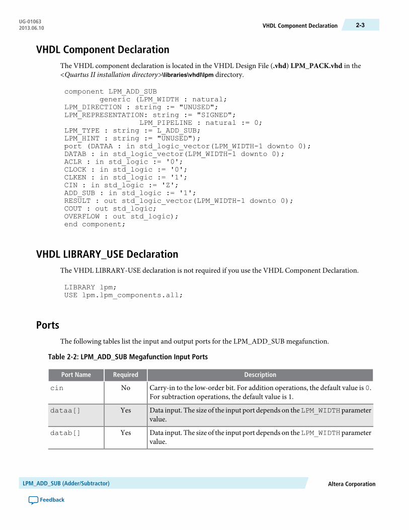
VHDL Component DeclarationThe VHDL component declaration is located in the VHDL Design File (.vhd) LPM_PACK.vhd in the<Quartus II installation directory>\libraries\vhdl\lpm directory.
component LPM_ADD_SUBgeneric (LPM_WIDTH : natural;
LPM_DIRECTION : string := "UNUSED";LPM_REPRESENTATION: string := "SIGNED";
LPM_PIPELINE : natural := 0;LPM_TYPE : string := L_ADD_SUB;LPM_HINT : string := "UNUSED");port (DATAA : in std_logic_vector(LPM_WIDTH-1 downto 0);DATAB : in std_logic_vector(LPM_WIDTH-1 downto 0);ACLR : in std_logic := '0';CLOCK : in std_logic := '0';CLKEN : in std_logic := '1';CIN : in std_logic := 'Z';ADD_SUB : in std_logic := '1';RESULT : out std_logic_vector(LPM_WIDTH-1 downto 0);COUT : out std_logic;OVERFLOW : out std_logic);end component;
VHDL LIBRARY_USE DeclarationThe VHDL LIBRARY-USE declaration is not required if you use the VHDL Component Declaration.
LIBRARY lpm;USE lpm.lpm_components.all;
PortsThe following tables list the input and output ports for the LPM_ADD_SUB megafunction.
Table 2-2: LPM_ADD_SUB Megafunction Input Ports
DescriptionRequiredPort Name
Carry-in to the low-order bit. For addition operations, the default value is 0.For subtraction operations, the default value is 1.
Nocin
Data input. The size of the input port depends on theLPM_WIDTH parametervalue.
Yesdataa[]
Data input. The size of the input port depends on theLPM_WIDTH parametervalue.
Yesdatab[]
Altera CorporationLPM_ADD_SUB (Adder/Subtractor)
Feedback
2-3VHDL Component DeclarationUG-010632013.06.10

DescriptionRequiredPort Name
Optional input port to enable dynamic switching between the adder andsubtractor functions. If theLPM_DIRECTIONparameter is used,add_subcannot be used. If omitted, the default value is ADD. Altera recommends thatyou use the LPM_DIRECTION parameter to specify the operation of theLPM_ADD_SUB function, rather than assigning a constant to the add_subport.
Noadd_sub
Input for pipelined usage. The clock port provides the clock input for apipelined operation. For LPM_PIPELINE values other than 0 (default), theclock port must be enabled.
Noclock
Clock enable for pipelined usage. When the clken port is asserted high, theadder/subtractor operation takes place. When the signal is low, no operationoccurs. If omitted, the default value is 1.
Noclken
Asynchronous clear for pipelined usage. The pipeline initializes to anundefined (X) logic level. The aclr port can be used at any time to reset thepipeline to all 0s, asynchronously to the clock signal.
Noaclr
Table 2-3: LPM_ADD_SUB Megafunction Output Ports
DescriptionRequiredPort Name
Data output. The size of the output port depends on the LPM_WIDTHparameter value.
Yesresult[]
Carry-out (borrow-in) of the most significant bit (MSB). The cout port hasa physical interpretation as the carry-out (borrow-in) of the MSB. The coutport detects overflow in UNSIGNED operations. The cout port operates inthe same manner for SIGNED and UNSIGNED operations.
Nocout
Optional overflow exception output. The overflow port has a physicalinterpretation as the XOR of the carry-in to the MSB with the carry-out oftheMSB. The overflow port asserts when results exceed the available precision,and is used only when the LPM_REPRESENTATION parameter value isSIGNED.
Nooverflow
ParametersThe following table lists the LPM_ADD_SUB megafunction parameters.
Table 2-4: LPM_ADD_SUB Megafunction Parameters
DescriptionRequiredTypeParameter Name
Specifies the widths of the dataa[], datab[],and result[] ports.
YesIntegerLPM_WIDTH
LPM_ADD_SUB (Adder/Subtractor)Altera Corporation
Feedback
UG-01063Parameters2-4 2013.06.10
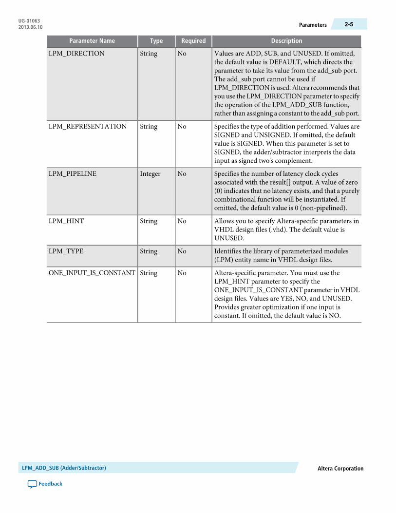
DescriptionRequiredTypeParameter Name
Values are ADD, SUB, and UNUSED. If omitted,the default value is DEFAULT, which directs theparameter to take its value from the add_sub port.The add_sub port cannot be used ifLPM_DIRECTION is used.Altera recommends thatyou use the LPM_DIRECTIONparameter to specifythe operation of the LPM_ADD_SUB function,rather than assigning a constant to the add_sub port.
NoStringLPM_DIRECTION
Specifies the type of addition performed. Values areSIGNED and UNSIGNED. If omitted, the defaultvalue is SIGNED. When this parameter is set toSIGNED, the adder/subtractor interprets the datainput as signed two's complement.
NoStringLPM_REPRESENTATION
Specifies the number of latency clock cyclesassociated with the result[] output. A value of zero(0) indicates that no latency exists, and that a purelycombinational function will be instantiated. Ifomitted, the default value is 0 (non-pipelined).
NoIntegerLPM_PIPELINE
Allows you to specify Altera-specific parameters inVHDL design files (.vhd). The default value isUNUSED.
NoStringLPM_HINT
Identifies the library of parameterized modules(LPM) entity name in VHDL design files.
NoStringLPM_TYPE
Altera-specific parameter. You must use theLPM_HINT parameter to specify theONE_INPUT_IS_CONSTANTparameter inVHDLdesign files. Values are YES, NO, and UNUSED.Provides greater optimization if one input isconstant. If omitted, the default value is NO.
NoStringONE_INPUT_IS_CONSTANT
Altera CorporationLPM_ADD_SUB (Adder/Subtractor)
Feedback
2-5ParametersUG-010632013.06.10
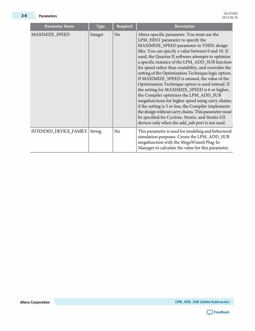
DescriptionRequiredTypeParameter Name
Altera-specific parameter. You must use theLPM_HINT parameter to specify theMAXIMIZE_SPEED parameter in VHDL designfiles. You can specify a value between 0 and 10. Ifused, the Quartus II software attempts to optimizea specific instance of the LPM_ADD_SUB functionfor speed rather than routability, and overrides thesetting of the Optimization Technique logic option.If MAXIMIZE_SPEED is unused, the value of theOptimization Technique option is used instead. Ifthe setting for MAXIMIZE_SPEED is 6 or higher,the Compiler optimizes the LPM_ADD_SUBmegafunctions for higher speed using carry chains;if the setting is 5 or less, the Compiler implementsthe designwithout carry chains. This parametermustbe specified for Cyclone, Stratix, and Stratix GXdevices only when the add_sub port is not used.
NoIntegerMAXIMIZE_SPEED
This parameter is used for modeling and behavioralsimulation purposes. Create the LPM_ADD_SUBmegafunction with the MegaWizard Plug-InManager to calculate the value for this parameter.
NoStringINTENDED_DEVICE_FAMILY
LPM_ADD_SUB (Adder/Subtractor)Altera Corporation
Feedback
UG-01063Parameters2-6 2013.06.10

3LPM_COMPARE (Comparator)
2013.06.10UG-01063 Subscribe Feedback
The LPM_COMPARE megafunction compares the value of two sets of data to determine the relationshipbetween them. In its simplest form, you can use an exclusive-OR gate to determine whether two bits of dataare equal.
The following figure shows the ports for the LPM_COMPARE megafunction.
Figure 3-1: LPM_COMPARE Ports
clken
dataa[]
inst
LPM_COMPAREalb
clock
aclr
datab[]
aeb
agb
ageb
aneb
aleb
FeaturesThe LPM_COMPARE megafunction offers the following features:
• Generates a comparator function to compare two sets of data• Supports data width of 1–256 bits• Supports data representation format such as signed and unsigned• Produces the following output types:
• alb (input A is less than input B)• aeb (input A is equal to input B)• agb (input A is greater than input B)• ageb (input A is greater than or equal to input B)• aneb (input A is not equal to input B)• aleb (input A is less than or equal to input B)
ISO9001:2008Registered
© 2013 Altera Corporation. All rights reserved. ALTERA, ARRIA, CYCLONE, HARDCOPY, MAX, MEGACORE, NIOS, QUARTUS and STRATIXwords and logos are trademarks of Altera Corporation and registered in the U.S. Patent and Trademark Office and in other countries. All other wordsand logos identified as trademarks or service marks are the property of their respective holders as described at www.altera.com/common/legal.html.Altera warrants performance of its semiconductor products to current specifications in accordance with Altera's standard warranty, but reserves theright to make changes to any products and services at any time without notice. Altera assumes no responsibility or liability arising out of the applicationor use of any information, product, or service described herein except as expressly agreed to in writing by Altera. Altera customers are advised toobtain the latest version of device specifications before relying on any published information and before placing orders for products or services.
www.altera.com
101 Innovation Drive, San Jose, CA 95134

• Supports optional asynchronous clear and clock enable input ports• Assigns the datab[] input to a constant• Supports pipelining with configurable output latency
Resource Utilization and PerformanceThe following table provides resource utilization and performance information for the LPM_COMPAREmegafunction.
Table 3-1: LPM_COMPARE Resource Utilization and Performance
fMAX (MHz)2
Logic Usage
Output latencyInput data
widthDevice family Adaptive Logic
Module (ALM)
Dedicated Lo-gic Register
(DLR)
Adaptive Look-Up Table(ALUT)
54730428
Stratix III 35771064596
342185017110256
54830428
Stratix IV 36367064596
313185017110256
Verilog HDL PrototypeThe following Verilog HDL prototype is located in the Verilog Design File (.v) lpm.v in the <Quartus IIinstallation directory>\eda\synthesis directory.
module lpm_compare ( alb, aeb, agb, aleb, aneb, ageb, dataa, datab,clock, clken, aclr );parameter lpm_type = "lpm_compare";parameter lpm_width = 1;parameter lpm_representation = "UNSIGNED";parameter lpm_pipeline = 0;parameter lpm_hint = "UNUSED";input [lpm_width-1:0] dataa, datab;input clock;input clken;input aclr;output alb, aeb, agb, aleb, aneb, ageb;endmodule
2 The performance of the megafunction is dependant on the value of the maximum allowable ceiling fMAX thatthe selected device can achieve. Therefore, results may vary from the numbers stated in this column.
LPM_COMPARE (Comparator)Altera Corporation
Feedback
UG-01063Resource Utilization and Performance3-2 2013.06.10
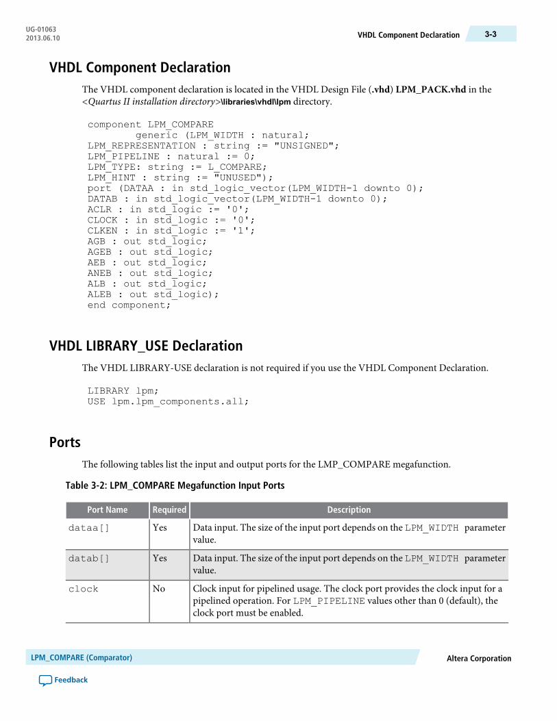
VHDL Component DeclarationThe VHDL component declaration is located in the VHDL Design File (.vhd) LPM_PACK.vhd in the<Quartus II installation directory>\libraries\vhdl\lpm directory.
component LPM_COMPAREgeneric (LPM_WIDTH : natural;
LPM_REPRESENTATION : string := "UNSIGNED";LPM_PIPELINE : natural := 0;LPM_TYPE: string := L_COMPARE;LPM_HINT : string := "UNUSED");port (DATAA : in std_logic_vector(LPM_WIDTH-1 downto 0);DATAB : in std_logic_vector(LPM_WIDTH-1 downto 0);ACLR : in std_logic := '0';CLOCK : in std_logic := '0';CLKEN : in std_logic := '1';AGB : out std_logic;AGEB : out std_logic;AEB : out std_logic;ANEB : out std_logic;ALB : out std_logic;ALEB : out std_logic);end component;
VHDL LIBRARY_USE DeclarationThe VHDL LIBRARY-USE declaration is not required if you use the VHDL Component Declaration.
LIBRARY lpm;USE lpm.lpm_components.all;
PortsThe following tables list the input and output ports for the LMP_COMPARE megafunction.
Table 3-2: LPM_COMPARE Megafunction Input Ports
DescriptionRequiredPort Name
Data input. The size of the input port depends on the LPM_WIDTH parametervalue.
Yesdataa[]
Data input. The size of the input port depends on the LPM_WIDTH parametervalue.
Yesdatab[]
Clock input for pipelined usage. The clock port provides the clock input for apipelined operation. For LPM_PIPELINE values other than 0 (default), theclock port must be enabled.
Noclock
Altera CorporationLPM_COMPARE (Comparator)
Feedback
3-3VHDL Component DeclarationUG-010632013.06.10

DescriptionRequiredPort Name
Clock enable for pipelined usage. When the clken port is asserted high, thecomparison operation takes place. When the signal is low, no operation occurs.If omitted, the default value is 1.
Noclken
Asynchronous clear for pipelined usage. The pipeline initializes to an undefined(X) logic level. The aclr port can be used at any time to reset the pipeline toall 0s, asynchronously to the clock signal.
Noaclr
Table 3-3: LPM_COMPARE Megafunction Output Ports
DescriptionRequiredPort Name
Output port for the comparator. Asserted if input A is less than input B.Noalb
Output port for the comparator. Asserted if input A is equal to input B.Noaeb
Output port for the comparator. Asserted if input A is greater than input B.Noagb
Output port for the comparator. Asserted if input A is greater than or equalto input B.
Noageb
Output port for the comparator. Asserted if input A is not equal to input B.Noaneb
Output port for the comparator. Asserted if input A is less than or equal toinput B.
Noaleb
ParametersThe following table lists the parameters for the LPM_COMPARE megafunction.
Table 3-4: LPM_COMPARE Megafunction Parameters
DescriptionRequiredTypeParameter Name
Specifies the widths of the dataa[] and datab[]ports.
YesIntegerLPM_WIDTH
Specifies the type of comparison performed.Values are SIGNED and UNSIGNED. If omitted,the default value is UNSIGNED. When thisparameter value is set to SIGNED, the comparatorinterprets the data input as signed two'scomplement.
NoStringLPM_REPRESENTATION
Specifies the number of clock cycles of latencyassociatedwith the alb, aeb, agb, ageb, aleb, or aneboutput. A value of zero (0) indicates that no latencyexists, and that a purely combinational functionwill be instantiated. If omitted, the default valueis 0 (non-pipelined).
NoIntegerLPM_PIPELINE
LPM_COMPARE (Comparator)Altera Corporation
Feedback
UG-01063Parameters3-4 2013.06.10
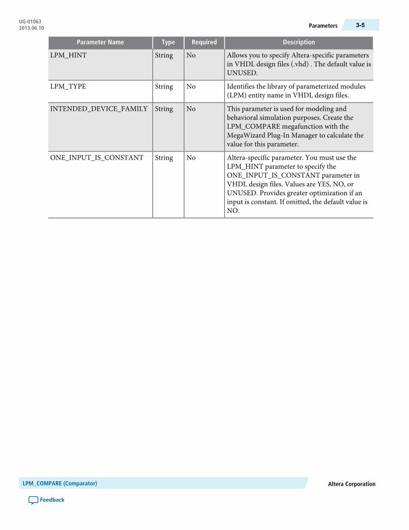
DescriptionRequiredTypeParameter Name
Allows you to specify Altera-specific parametersin VHDL design files (.vhd) . The default value isUNUSED.
NoStringLPM_HINT
Identifies the library of parameterized modules(LPM) entity name in VHDL design files.
NoStringLPM_TYPE
This parameter is used for modeling andbehavioral simulation purposes. Create theLPM_COMPARE megafunction with theMegaWizard Plug-In Manager to calculate thevalue for this parameter.
NoStringINTENDED_DEVICE_FAMILY
Altera-specific parameter. You must use theLPM_HINT parameter to specify theONE_INPUT_IS_CONSTANT parameter inVHDL design files. Values are YES, NO, orUNUSED. Provides greater optimization if aninput is constant. If omitted, the default value isNO.
NoStringONE_INPUT_IS_CONSTANT
Altera CorporationLPM_COMPARE (Comparator)
Feedback
3-5ParametersUG-010632013.06.10
4LPM_COUNTER (Counter)
2013.06.10UG-01063 Subscribe Feedback
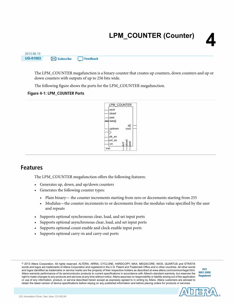
The LPM_COUNTER megafunction is a binary counter that creates up counters, down counters and up ordown counters with outputs of up to 256 bits wide.
The following figure shows the ports for the LPM_COUNTER megafunction.
Figure 4-1: LPM_COUNTER Ports
ssclrsload
inst
LPM_COUNTER
q[]
sset
cout
data[]
clk_encnt_encin ac
lraloa
daset
updown
FeaturesThe LPM_COUNTER megafunction offers the following features:
• Generates up, down, and up/down counters• Generates the following counter types:
• Plain binary— the counter increments starting from zero or decrements starting from 255• Modulus—the counter increments to or decrements from the modulus value specified by the user
and repeats
• Supports optional synchronous clear, load, and set input ports• Supports optional asynchronous clear, load, and set input ports• Supports optional count enable and clock enable input ports• Supports optional carry-in and carry-out ports
ISO9001:2008Registered
© 2013 Altera Corporation. All rights reserved. ALTERA, ARRIA, CYCLONE, HARDCOPY, MAX, MEGACORE, NIOS, QUARTUS and STRATIXwords and logos are trademarks of Altera Corporation and registered in the U.S. Patent and Trademark Office and in other countries. All other wordsand logos identified as trademarks or service marks are the property of their respective holders as described at www.altera.com/common/legal.html.Altera warrants performance of its semiconductor products to current specifications in accordance with Altera's standard warranty, but reserves theright to make changes to any products and services at any time without notice. Altera assumes no responsibility or liability arising out of the applicationor use of any information, product, or service described herein except as expressly agreed to in writing by Altera. Altera customers are advised toobtain the latest version of device specifications before relying on any published information and before placing orders for products or services.
www.altera.com
101 Innovation Drive, San Jose, CA 95134

Resource Utilization and PerformanceThe following table provides resource utilization and performance information for the LPM_COUNTERmegafunction.
Table 4-1: LPM_COUNTER Resource Utilization and Performance
fMAX (MHz)3
Logic Usage
Output latencyInput data
widthDevice family Adaptive Logic
Module (ALM)Dedicated Lo-gic Register
(DLR)
Adaptive Look-Up Table(ALUT)
723649-4
Stratix III
808589-8
70591617-16
583132425-24
489173233-32
329336465-64
768649-4
Stratix IV
896589-8
82591617-16
716132425-24
639173233-32
470336465-64
Verilog HDL PrototypeThe following Verilog HDL prototype is located in the Verilog Design File (.v) lpm.v in the <Quartus IIinstallation directory>\eda\synthesis directory.
module lpm_counter ( q, data, clock, cin, cout, clk_en, cnt_en, updown,aset, aclr, aload, sset, sclr, sload, eq );parameter lpm_type = "lpm_counter";parameter lpm_width = 1;parameter lpm_modulus = 0;parameter lpm_direction = "UNUSED";parameter lpm_avalue = "UNUSED";parameter lpm_svalue = "UNUSED";parameter lpm_pvalue = "UNUSED";
3 The performance of the megafunction is dependant on the value of the maximum allowable ceiling fMAX thatthe selected device can achieve. Therefore, results may vary from the numbers stated in this column.
LPM_COUNTER (Counter)Altera Corporation
Feedback
UG-01063Resource Utilization and Performance4-2 2013.06.10
parameter lpm_port_updown = "PORT_CONNECTIVITY";parameter lpm_hint = "UNUSED";output [lpm_width-1:0] q;output cout;output [15:0] eq;input cin;input [lpm_width-1:0] data;input clock, clk_en, cnt_en, updown;input aset, aclr, aload;input sset, sclr, sload;endmodule
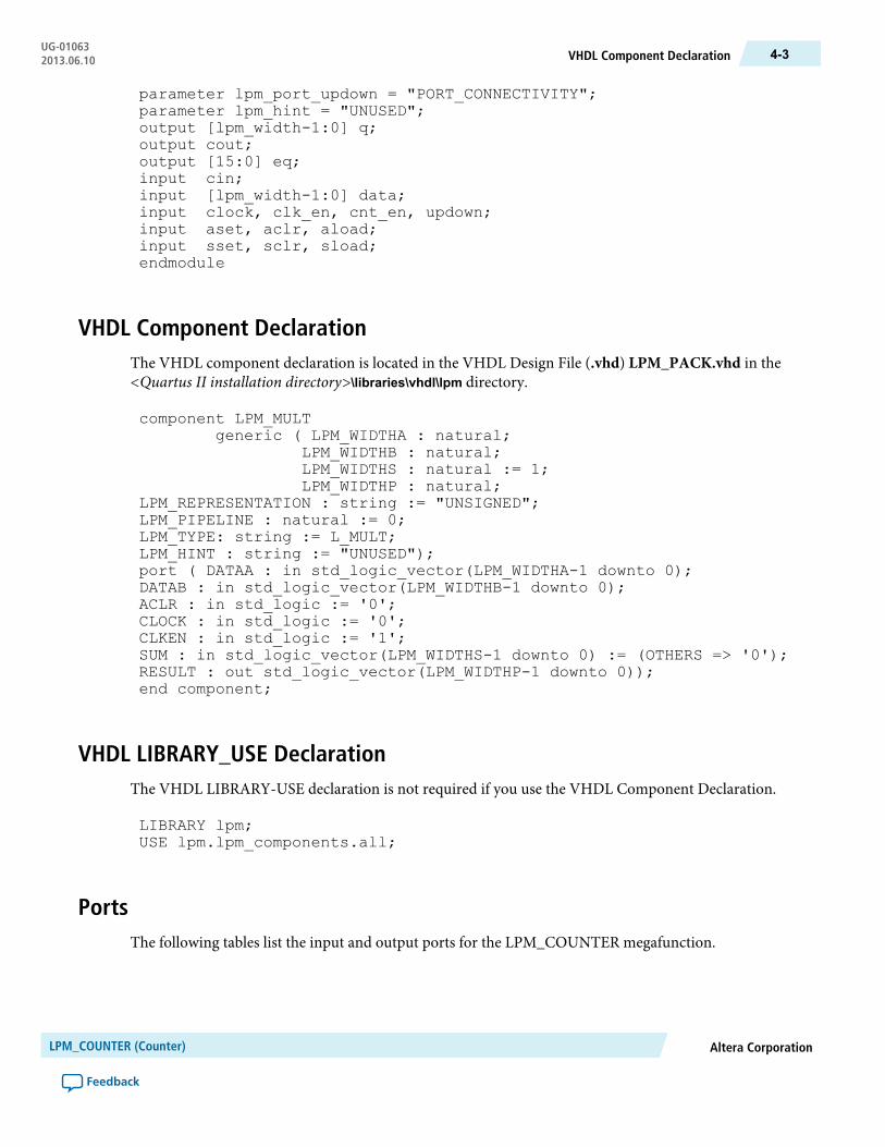
VHDL Component DeclarationThe VHDL component declaration is located in the VHDL Design File (.vhd) LPM_PACK.vhd in the<Quartus II installation directory>\libraries\vhdl\lpm directory.
component LPM_MULTgeneric ( LPM_WIDTHA : natural;
LPM_WIDTHB : natural;LPM_WIDTHS : natural := 1;LPM_WIDTHP : natural;
LPM_REPRESENTATION : string := "UNSIGNED";LPM_PIPELINE : natural := 0;LPM_TYPE: string := L_MULT;LPM_HINT : string := "UNUSED");port ( DATAA : in std_logic_vector(LPM_WIDTHA-1 downto 0);DATAB : in std_logic_vector(LPM_WIDTHB-1 downto 0);ACLR : in std_logic := '0';CLOCK : in std_logic := '0';CLKEN : in std_logic := '1';SUM : in std_logic_vector(LPM_WIDTHS-1 downto 0) := (OTHERS => '0');RESULT : out std_logic_vector(LPM_WIDTHP-1 downto 0));end component;
VHDL LIBRARY_USE DeclarationThe VHDL LIBRARY-USE declaration is not required if you use the VHDL Component Declaration.
LIBRARY lpm;USE lpm.lpm_components.all;
PortsThe following tables list the input and output ports for the LPM_COUNTER megafunction.
Altera CorporationLPM_COUNTER (Counter)
Feedback
4-3VHDL Component DeclarationUG-010632013.06.10

Table 4-2: LPM_COUNTER Megafunction Input Ports
DescriptionRequiredPort Name
Parallel data input to the counter. The size of the input port depends onthe LPM_WIDTH parameter value.
Nodata[]
Positive-edge-triggered clock input.Yesclock
Clock enable input to enable all synchronous activities. If omitted, thedefault value is 1.
Noclk_en
Count enable input to disable the countwhen asserted lowwithout affectingsload, sset, or sclr. If omitted, the default value is 1.
Nocnt_en
Controls the direction of the count. When asserted high (1), the countdirection is up, and when asserted low (0), the count direction is down. Ifthe LPM_DIRECTION parameter is used, the updown port cannot beconnected. IfLPM_DIRECTION is not used, theupdown port is optional.If omitted, the default value is up (1).
Noupdown
Carry-in to the low-order bit. For up counters, the behavior of the cininput is identical to the behavior of the cnt_en input. If omitted, thedefault value is 1 (VCC).
Nocin
Asynchronous clear input. If both aset and aclr are used and asserted,aclr overrides aset. If omitted, the default value is 0 (disabled).
Noaclr
Asynchronous set input. Specifies the q[] outputs as all 1s, or to the valuespecified by the LPM_AVALUE parameter. If both the aset and aclrports are used and asserted, the value of the aclr port overrides the valueof the aset port. If omitted, the default value is 0, disabled.
Noaset
Asynchronous load input that asynchronously loads the counter with thevalue on the data input. When the aload port is used, the data[] portmust be connected. If omitted, the default value is 0, disabled.
Noaload
Synchronous clear input that clears the counter on the next active clockedge. If both the sset and sclr ports are used and asserted, the value ofthe sclr port overrides the value of the sset port. If omitted, the defaultvalue is 0, disabled.
Nosclr
Synchronous set input that sets the counter on the next active clock edge.Specifies the value of the q outputs as all 1s, or to the value specified by theLPM_SVALUE parameter. If both the sset and sclr ports are used andasserted, the value of the sclr port overrides the value of the sset port.If omitted, the default value is 0 (disabled).
Nosset
Synchronous load input that loads the counter with data[] on the nextactive clock edge. When the sload port is used, the data[] port mustbe connected. If omitted, the default value is 0 (disabled).
Nosload
LPM_COUNTER (Counter)Altera Corporation
Feedback
UG-01063Ports4-4 2013.06.10
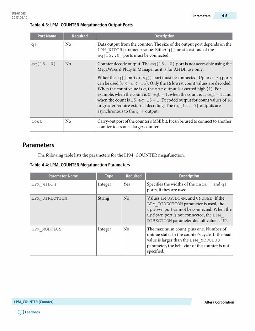
Table 4-3: LPM_COUNTER Megafunction Output Ports
DescriptionRequiredPort Name
Data output from the counter. The size of the output port depends on theLPM_WIDTH parameter value. Either q[] or at least one of theeq[15..0] ports must be connected.
Noq[]
Counter decode output. The eq[15..0] port is not accessible using theMegaWizard Plug-In Manager as it is for AHDL use only.
Either the q[] port or eq[] port must be connected. Up to c eq portscan be used (0 <= c <= 15). Only the 16 lowest count values are decoded.When the count value is c, the eqc output is asserted high (1). Forexample, when the count is 0, eq0 = 1, when the count is 1, eq1 = 1, andwhen the count is 15, eq 15 = 1. Decoded output for count values of 16or greater require external decoding. The eq[15..0] outputs areasynchronous to the q[] output.
Noeq[15..0]
Carry-out port of the counter'sMSBbit. It can be used to connect to anothercounter to create a larger counter.
Nocout
ParametersThe following table lists the parameters for the LPM_COUNTER megafunction.
Table 4-4: LPM_COUNTER Megafunction Parameters
DescriptionRequiredTypeParameter Name
Specifies the widths of the data[] and q[]ports, if they are used.
YesIntegerLPM_WIDTH
Values are UP, DOWN, and UNUSED. If theLPM_DIRECTION parameter is used, theupdown port cannot be connected. When theupdown port is not connected, the LPM_DIRECTION parameter default value is UP.
NoStringLPM_DIRECTION
The maximum count, plus one. Number ofunique states in the counter's cycle. If the loadvalue is larger than the LPM_MODULUSparameter, the behavior of the counter is notspecified.
NoIntegerLPM_MODULUS
Altera CorporationLPM_COUNTER (Counter)
Feedback
4-5ParametersUG-010632013.06.10

DescriptionRequiredTypeParameter Name
Constant value that is loaded when aset isasserted high. If the value specified is largerthan or equal to <modulus>, the behavior ofthe counter is an undefined (X) logic level,where <modulus> is LPM_MODULUS, ifpresent, or 2 ^ LPM_WIDTH. Alterarecommends that you specify this value as adecimal number for AHDL designs.
NoInteger/StringLPM_AVALUE
Constant value that is loaded on the rising edgeof the clock port when either the sset port orthe sconst port is asserted high. The LPM_SVALUE parameter must be used when thesconst port is used. Altera recommends thatyou specify this value as a decimal number forAHDL designs.
NoInteger/StringLPM_SVALUE
Allows you to specifyAltera-specific parametersin VHDL design files (.vhd). The default valueis UNUSED.
NoStringLPM_HINT
Identifies the library of parameterizedmodules(LPM) entity name in VHDL design files.
NoStringLPM_TYPE
This parameter is used for modeling andbehavioral simulation purposes. Create theLPM_COUNTERmegafunction with theMegaWizard Plug-In Manager to calculate thevalue for this parameter.
NoStringINTENDED_DEVICE_FAMILY
Altera-specific parameter. You must use theLPM_HINT parameter to specify the CARRY_CNT_EN parameter in VHDL design files.Values are SMART, ON, OFF, and UNUSED.Enables the LPM_COUNTER function topropagate thecnt_en signal through the carrychain. In some cases, the CARRY_CNT_ENparameter setting might have a slight impacton the speed, so you might want to turn it off.The default value is SMART, which providesthe best trade-off between size and speed.
NoStringCARRY_CNT_EN
LPM_COUNTER (Counter)Altera Corporation
Feedback
UG-01063Parameters4-6 2013.06.10

DescriptionRequiredTypeParameter Name
Altera-specific parameter. You must use theLPM_HINT parameter to specify theLABWIDE_SCLR parameter in VHDL designfiles. Values are ON, OFF, or UNUSED. Thedefault value is ON. Allows you to disable theuse of the LAB-wide sclr feature found inobsoleted device families. Turning this optionoff increases the chances of fully using thepartially filled LABs, and thusmay allow higherlogic density when SCLR does not apply to acomplete LAB. This parameter is available forbackward compatibility, and Alterarecommends you not to use this parameter.
NoStringLABWIDE_SCLR
Specifies the usage of the updown input port.If omitted the default value is PORT_CONNECTIVITY. When the port value is setto PORT_USED, the port is treated as used.When the port value is set to PORT_UNUSED,the port is treated as unused. When the portvalue is set to PORT_CONNECTIVITY, theport usage is determined by checking the portconnectivity.
NoStringLPM_PORT_UPDOWN
Altera CorporationLPM_COUNTER (Counter)
Feedback
4-7ParametersUG-010632013.06.10
5LPM_DIVIDE (Divider)
2013.06.10UG-01063 Subscribe Feedback
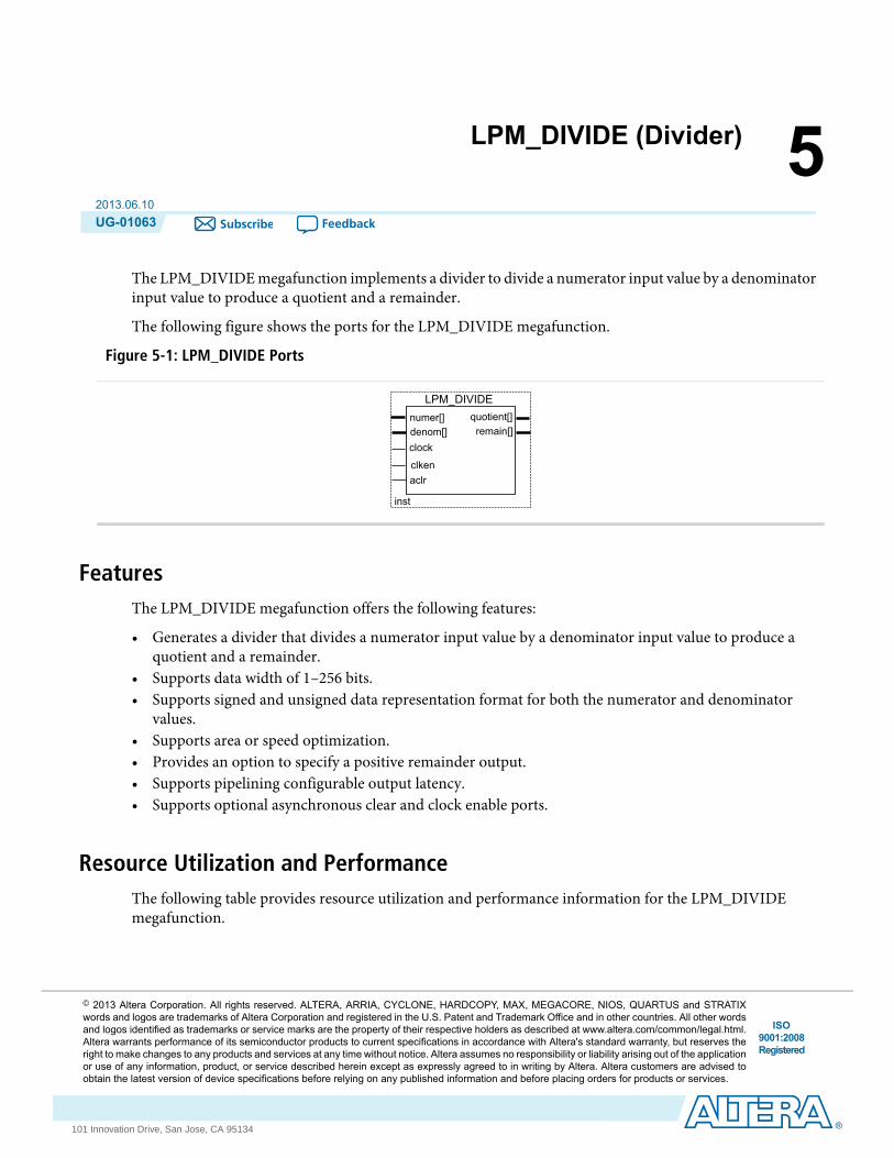
The LPM_DIVIDE megafunction implements a divider to divide a numerator input value by a denominatorinput value to produce a quotient and a remainder.
The following figure shows the ports for the LPM_DIVIDE megafunction.
Figure 5-1: LPM_DIVIDE Ports
numer[]denom[]
inst
LPM_DIVIDEquotient[]
clken
clock
aclr
remain[]
FeaturesThe LPM_DIVIDE megafunction offers the following features:
• Generates a divider that divides a numerator input value by a denominator input value to produce aquotient and a remainder.
• Supports data width of 1–256 bits.• Supports signed and unsigned data representation format for both the numerator and denominator
values.• Supports area or speed optimization.• Provides an option to specify a positive remainder output.• Supports pipelining configurable output latency.• Supports optional asynchronous clear and clock enable ports.
Resource Utilization and PerformanceThe following table provides resource utilization and performance information for the LPM_DIVIDEmegafunction.
ISO9001:2008Registered
© 2013 Altera Corporation. All rights reserved. ALTERA, ARRIA, CYCLONE, HARDCOPY, MAX, MEGACORE, NIOS, QUARTUS and STRATIXwords and logos are trademarks of Altera Corporation and registered in the U.S. Patent and Trademark Office and in other countries. All other wordsand logos identified as trademarks or service marks are the property of their respective holders as described at www.altera.com/common/legal.html.Altera warrants performance of its semiconductor products to current specifications in accordance with Altera's standard warranty, but reserves theright to make changes to any products and services at any time without notice. Altera assumes no responsibility or liability arising out of the applicationor use of any information, product, or service described herein except as expressly agreed to in writing by Altera. Altera customers are advised toobtain the latest version of device specifications before relying on any published information and before placing orders for products or services.
www.altera.com
101 Innovation Drive, San Jose, CA 95134

Table 5-1: LPM_DIVIDE Resource Utilization and Performance
fMAX (MHz)
Logic Usage
Output latencyInput data
widthDevice family Adaptive Logic
Module (ALM)Dedicated Lo-gic Register
(DLR)
Adaptive Look-Up Table(ALUT)
133700131110
Stratix III 7163501017530
412623043451064
138700131110
Stratix IV 8264201018530
482634043471064
Verilog HDL PrototypeThe following Verilog HDL prototype is located in the Verilog Design File (.v) lpm.v in the <Quartus IIinstallation directory>\eda\synthesis directory.
module lpm_divide ( quotient, remain, numer, denom, clock, clken, aclr);parameter lpm_type = "lpm_divide";parameter lpm_widthn = 1;parameter lpm_widthd = 1;parameter lpm_nrepresentation = "UNSIGNED";parameter lpm_drepresentation = "UNSIGNED";parameter lpm_remainderpositive = "TRUE";parameter lpm_pipeline = 0;parameter lpm_hint = "UNUSED";input clock;input clken;input aclr;input [lpm_widthn-1:0] numer;input [lpm_widthd-1:0] denom;output [lpm_widthn-1:0] quotient;output [lpm_widthd-1:0] remain;endmodule
VHDL Component DeclarationThe VHDL component declaration is located in the VHDL Design File (.vhd) LPM_PACK.vhd in the<Quartus II installation directory>\libraries\vhdl\lpm directory.
component LPM_DIVIDEgeneric (LPM_WIDTHN : natural;
LPM_WIDTHD : natural;LPM_NREPRESENTATION : string := "UNSIGNED";
LPM_DIVIDE (Divider)Altera Corporation
Feedback
UG-01063Verilog HDL Prototype5-2 2013.06.10
LPM_DREPRESENTATION : string := "UNSIGNED";LPM_PIPELINE : natural := 0;LPM_TYPE : string := L_DIVIDE;LPM_HINT : string := "UNUSED");port (NUMER : in std_logic_vector(LPM_WIDTHN-1 downto 0);DENOM : in std_logic_vector(LPM_WIDTHD-1 downto 0);ACLR : in std_logic := '0';CLOCK : in std_logic := '0';CLKEN : in std_logic := '1';QUOTIENT : out std_logic_vector(LPM_WIDTHN-1 downto 0);REMAIN : out std_logic_vector(LPM_WIDTHD-1 downto 0));end component;
VHDL LIBRARY_USE DeclarationThe VHDL LIBRARY-USE declaration is not required if you use the VHDL Component Declaration.
LIBRARY lpm;USE lpm.lpm_components.all;
PortsThe following tables list the input and output ports for the LPM_DIVIDE megafunction.
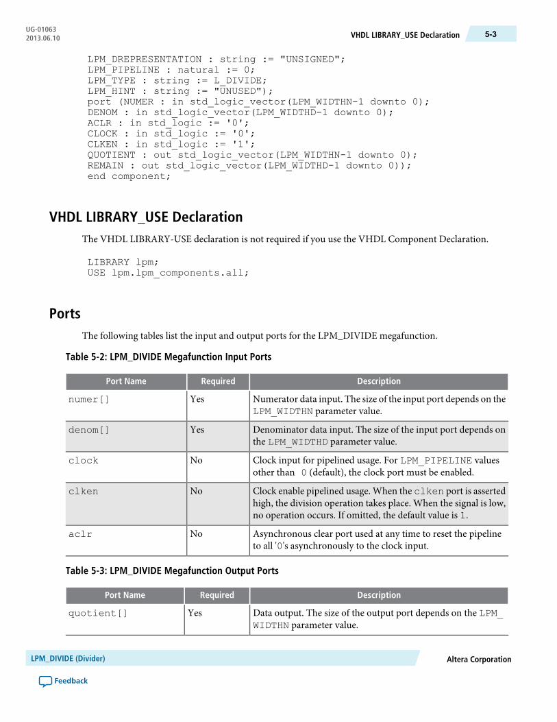
Table 5-2: LPM_DIVIDE Megafunction Input Ports
DescriptionRequiredPort Name
Numerator data input. The size of the input port depends on theLPM_WIDTHN parameter value.
Yesnumer[]
Denominator data input. The size of the input port depends onthe LPM_WIDTHD parameter value.
Yesdenom[]
Clock input for pipelined usage. For LPM_PIPELINE valuesother than 0 (default), the clock port must be enabled.
Noclock
Clock enable pipelined usage. When the clken port is assertedhigh, the division operation takes place. When the signal is low,no operation occurs. If omitted, the default value is 1.
Noclken
Asynchronous clear port used at any time to reset the pipelineto all '0's asynchronously to the clock input.
Noaclr
Table 5-3: LPM_DIVIDE Megafunction Output Ports
DescriptionRequiredPort Name
Data output. The size of the output port depends on the LPM_WIDTHN parameter value.
Yesquotient[]
Altera CorporationLPM_DIVIDE (Divider)
Feedback
5-3VHDL LIBRARY_USE DeclarationUG-010632013.06.10
DescriptionRequiredPort Name
Data output. The size of the output port depends on the LPM_WIDTHD parameter value.
Yesremain[]
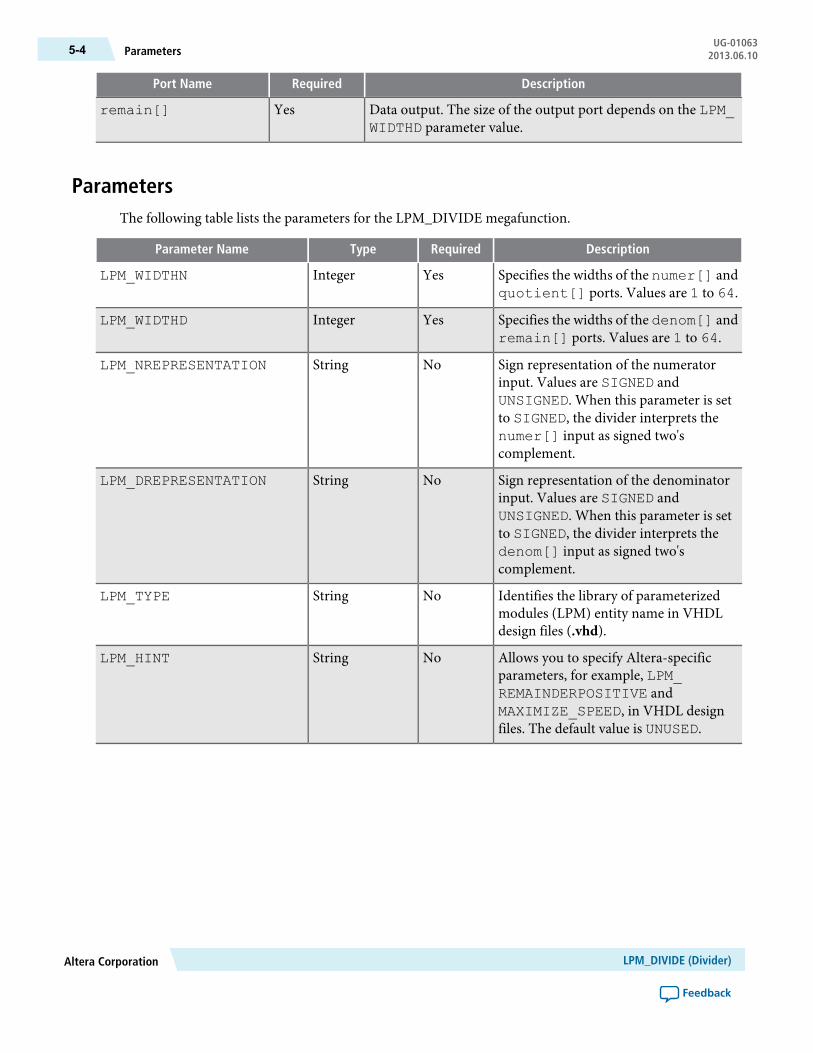
ParametersThe following table lists the parameters for the LPM_DIVIDE megafunction.
DescriptionRequiredTypeParameter Name
Specifies the widths of the numer[] andquotient[] ports. Values are 1 to 64.
YesIntegerLPM_WIDTHN
Specifies the widths of the denom[] andremain[] ports. Values are 1 to 64.
YesIntegerLPM_WIDTHD
Sign representation of the numeratorinput. Values are SIGNED andUNSIGNED. When this parameter is setto SIGNED, the divider interprets thenumer[] input as signed two'scomplement.
NoStringLPM_NREPRESENTATION
Sign representation of the denominatorinput. Values are SIGNED andUNSIGNED. When this parameter is setto SIGNED, the divider interprets thedenom[] input as signed two'scomplement.
NoStringLPM_DREPRESENTATION
Identifies the library of parameterizedmodules (LPM) entity name in VHDLdesign files (.vhd).
NoStringLPM_TYPE
Allows you to specify Altera-specificparameters, for example, LPM_REMAINDERPOSITIVE andMAXIMIZE_SPEED, in VHDL designfiles. The default value is UNUSED.
NoStringLPM_HINT
LPM_DIVIDE (Divider)Altera Corporation
Feedback
UG-01063Parameters5-4 2013.06.10
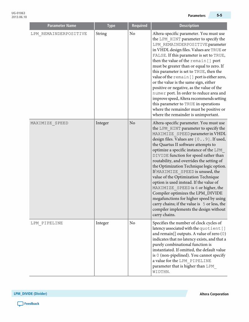
DescriptionRequiredTypeParameter Name
Altera-specific parameter. You must usethe LPM_HINT parameter to specify theLPM_REMAINDERPOSITIVEparameterinVHDLdesign files. Values areTRUE orFALSE. If this parameter is set to TRUE,then the value of the remain[] portmust be greater than or equal to zero. Ifthis parameter is set to TRUE, then thevalue of theremain[]port is either zero,or the value is the same sign, eitherpositive or negative, as the value of thenumer port. In order to reduce area andimprove speed,Altera recommends settingthis parameter to TRUE in operationswhere the remainder must be positive orwhere the remainder is unimportant.
NoStringLPM_REMAINDERPOSITIVE
Altera-specific parameter. You must usethe LPM_HINT parameter to specify theMAXIMIZE_SPEEDparameter inVHDLdesign files. Values are [0..9]. If used,the Quartus II software attempts tooptimize a specific instance of the LPM_DIVIDE function for speed rather thanroutability, and overrides the setting ofthe Optimization Technique logic option.If MAXIMIZE_SPEED is unused, thevalue of the Optimization Techniqueoption is used instead. If the value ofMAXIMIZE_SPEED is 6 or higher, theCompiler optimizes the LPM_DIVIDEmegafunctions for higher speed by usingcarry chains; if the value is 5 or less, thecompiler implements the design withoutcarry chains.
NoIntegerMAXIMIZE_SPEED
Specifies the number of clock cycles oflatency associatedwith thequotient[]and remain[] outputs. A value of zero (0)indicates that no latency exists, and that apurely combinational function isinstantiated. If omitted, the default valueis 0 (non-pipelined). You cannot specifya value for the LPM_PIPELINEparameter that is higher than LPM_WIDTHN.
NoIntegerLPM_PIPELINE
Altera CorporationLPM_DIVIDE (Divider)
Feedback
5-5ParametersUG-010632013.06.10

DescriptionRequiredTypeParameter Name
This parameter is used for modeling andbehavioral simulation purposes. Createthe LPM_DIVIDEmegafunctionwith theMegaWizardPlug-InManager to calculatethe value for this parameter.
NoStringINTENDED_DEVICE_FAMILY
Allows for more efficient fractional bitdivision to optimize logic on the leadingbits by providing the number of leadingGND to the LPM_DIVIDEmegafunction.Specify the number of leading GND onthe quotient output to this parameter.
NoIntegerSKIP_BITS
LPM_DIVIDE (Divider)Altera Corporation
Feedback
UG-01063Parameters5-6 2013.06.10
6LPM_MULT (Multiplier)
2013.06.10UG-01063 Subscribe Feedback
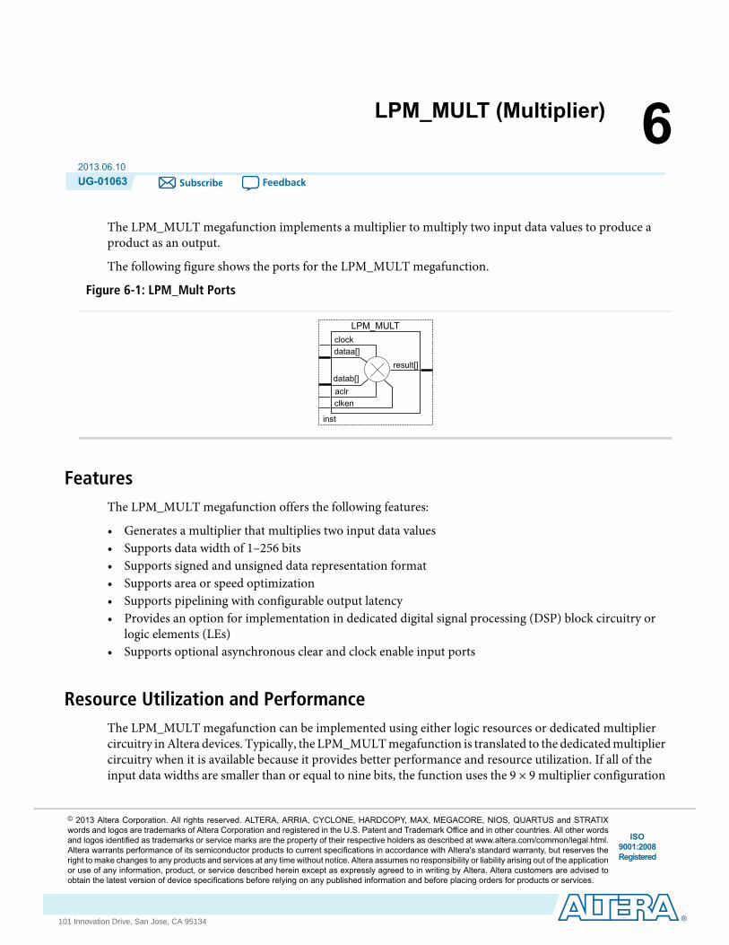
The LPM_MULT megafunction implements a multiplier to multiply two input data values to produce aproduct as an output.
The following figure shows the ports for the LPM_MULT megafunction.
Figure 6-1: LPM_Mult Ports
clockdataa[]
inst
LPM_MULT
datab[]aclr
result[]
clken
FeaturesThe LPM_MULT megafunction offers the following features:
• Generates a multiplier that multiplies two input data values• Supports data width of 1–256 bits• Supports signed and unsigned data representation format• Supports area or speed optimization• Supports pipelining with configurable output latency• Provides an option for implementation in dedicated digital signal processing (DSP) block circuitry or
logic elements (LEs)• Supports optional asynchronous clear and clock enable input ports
Resource Utilization and PerformanceThe LPM_MULT megafunction can be implemented using either logic resources or dedicated multipliercircuitry inAltera devices. Typically, the LPM_MULTmegafunction is translated to the dedicatedmultipliercircuitry when it is available because it provides better performance and resource utilization. If all of theinput data widths are smaller than or equal to nine bits, the function uses the 9 × 9 multiplier configuration
ISO9001:2008Registered
© 2013 Altera Corporation. All rights reserved. ALTERA, ARRIA, CYCLONE, HARDCOPY, MAX, MEGACORE, NIOS, QUARTUS and STRATIXwords and logos are trademarks of Altera Corporation and registered in the U.S. Patent and Trademark Office and in other countries. All other wordsand logos identified as trademarks or service marks are the property of their respective holders as described at www.altera.com/common/legal.html.Altera warrants performance of its semiconductor products to current specifications in accordance with Altera's standard warranty, but reserves theright to make changes to any products and services at any time without notice. Altera assumes no responsibility or liability arising out of the applicationor use of any information, product, or service described herein except as expressly agreed to in writing by Altera. Altera customers are advised toobtain the latest version of device specifications before relying on any published information and before placing orders for products or services.
www.altera.com
101 Innovation Drive, San Jose, CA 95134
in the dedicated multiplier. Otherwise, 18 × 18 multipliers are used to process data with widths between 10bits and 18 bits.
For information about the architecture of the DSP blocks and embedded multipliers, and for detailedinformation about the hardware conversion process, refer to theDSP block and embeddedmultiplier chaptersin the Stratix device series, Stratix II, Stratix III, and Cyclone II handbooks on the Literature and TechnicalDocumentation page.
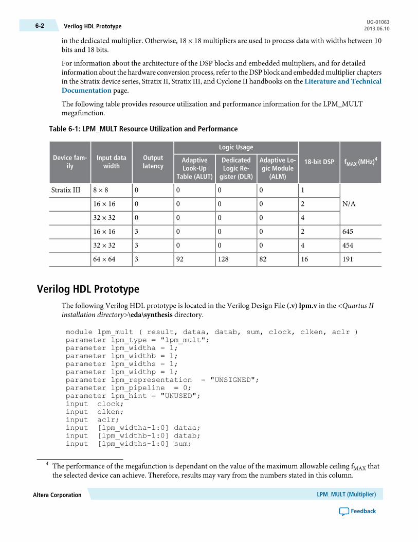
The following table provides resource utilization and performance information for the LPM_MULTmegafunction.
Table 6-1: LPM_MULT Resource Utilization and Performance
fMAX (MHz)418-bit DSP
Logic Usage
Outputlatency
Input datawidth
Device fam-ily
Adaptive Lo-gic Module
(ALM)
DedicatedLogic Re-
gister (DLR)
AdaptiveLook-Up
Table (ALUT)
N/A
100008 × 8Stratix III
2000016 × 16
4000032 × 32
6452000316 × 16
4544000332 × 32
191168212892364 × 64
Verilog HDL PrototypeThe following Verilog HDL prototype is located in the Verilog Design File (.v) lpm.v in the <Quartus IIinstallation directory>\eda\synthesis directory.
module lpm_mult ( result, dataa, datab, sum, clock, clken, aclr )parameter lpm_type = "lpm_mult";parameter lpm_widtha = 1;parameter lpm_widthb = 1;parameter lpm_widths = 1;parameter lpm_widthp = 1;parameter lpm_representation = "UNSIGNED";parameter lpm_pipeline = 0;parameter lpm_hint = "UNUSED";input clock;input clken;input aclr;input [lpm_widtha-1:0] dataa;input [lpm_widthb-1:0] datab;input [lpm_widths-1:0] sum;
4 The performance of the megafunction is dependant on the value of the maximum allowable ceiling fMAX thatthe selected device can achieve. Therefore, results may vary from the numbers stated in this column.
LPM_MULT (Multiplier)Altera Corporation
Feedback
UG-01063Verilog HDL Prototype6-2 2013.06.10

output [lpm_widthp-1:0] result;endmodule
VHDL Component DeclarationThe VHDL component declaration is located in the VHDL Design File (.vhd) LPM_PACK.vhd in the<Quartus II installation directory>\libraries\vhdl\lpm directory.
component LPM_MULTgeneric ( LPM_WIDTHA : natural;
LPM_WIDTHB : natural;LPM_WIDTHS : natural := 1;LPM_WIDTHP : natural;
LPM_REPRESENTATION : string := "UNSIGNED";LPM_PIPELINE : natural := 0;LPM_TYPE: string := L_MULT;LPM_HINT : string := "UNUSED");port ( DATAA : in std_logic_vector(LPM_WIDTHA-1 downto 0);DATAB : in std_logic_vector(LPM_WIDTHB-1 downto 0);ACLR : in std_logic := '0';CLOCK : in std_logic := '0';CLKEN : in std_logic := '1';SUM : in std_logic_vector(LPM_WIDTHS-1 downto 0) := (OTHERS => '0');RESULT : out std_logic_vector(LPM_WIDTHP-1 downto 0));end component;
VHDL LIBRARY_USE DeclarationThe VHDL LIBRARY-USE declaration is not required if you use the VHDL Component Declaration.
LIBRARY lpm;USE lpm.lpm_components.all;
PortsThe following tables list the input and output ports for the LPM_MULT megafunction.
Table 6-2: LPM_MULT Megafunction Input Ports
DescriptionRequiredPort Name
Data input. The size of the input port depends on the LPM_WIDTHAparameter value.
Yesdataa[]
Data input. The size of the input port depends on the LPM_WIDTHBparameter value.
Yesdatab[]
Altera CorporationLPM_MULT (Multiplier)
Feedback
6-3VHDL Component DeclarationUG-010632013.06.10

DescriptionRequiredPort Name
Clock input for pipelined usage. For LPM_PIPELINE values otherthan 0 (default), the clock port must be enabled.
Noclock
Clock enable for pipelined usage. When the clken port is assertedhigh, the adder/subtractor operation takes place. When the signal islow, no operation occurs. If omitted, the default value is 1.
Noclken
Asynchronous clear port used at any time to reset the pipeline to all0s, asynchronously to the clock signal. The pipeline initializes to anundefined (X) logic level. The outputs are a consistent, but non-zerovalue.
Noaclr
Table 6-3: LPM_MULT Megafunction Output Ports
DescriptionRequiredPort Name
Data output. The size of the output port depends on theLPM_WIDTHPparameter value. If LPM_WIDTHP < max (LPM_WIDTHA + LPM_WIDTHB, LPM_WIDTHS) or (LPM_WIDTHA + LPM_WIDTHS), onlythe LPM_WIDTHPMSBs are present.
Yesresult[]
ParametersThe following table lists the parameters for the LPM_MULT megafunction.
Table 6-4: LPM_MULT Megafunction Parameters
DescriptionRequiredTypeParameter Name
Specifies the width of the dataa[] port.YesIntegerLPM_WIDTHA
Specifies the width of the datab[] port.YesIntegerLPM_WIDTHB
Specifies the width of the result[] port.YesIntegerLPM_WIDTHP
Specifies the type ofmultiplication performed.Values are SIGNED and UNSIGNED. Ifomitted, the default value is UNSIGNED.When this parameter value is set to SIGNED,the multiplier interprets the data input assigned two's complement.
NoStringLPM_REPRESENTATION
LPM_MULT (Multiplier)Altera Corporation
Feedback
UG-01063Parameters6-4 2013.06.10
DescriptionRequiredTypeParameter Name
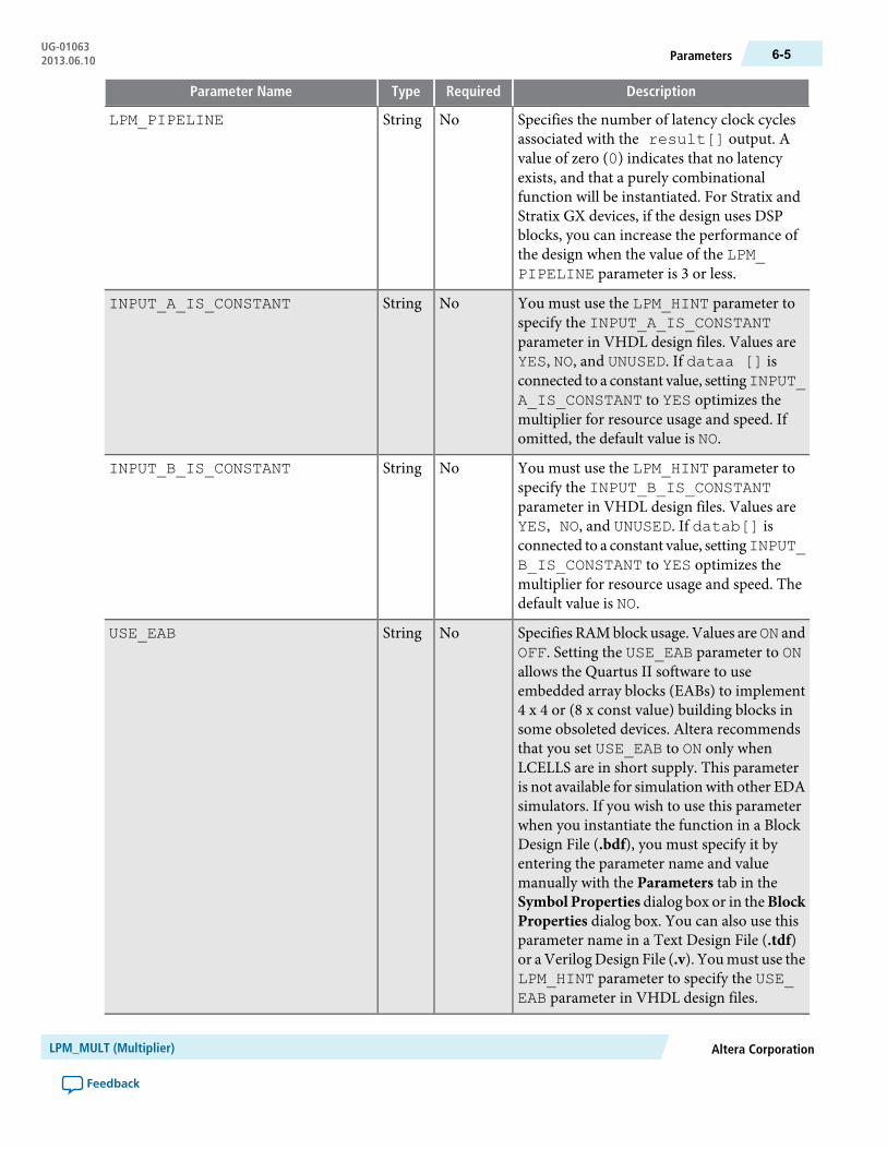
Specifies the number of latency clock cyclesassociated with the result[] output. Avalue of zero (0) indicates that no latencyexists, and that a purely combinationalfunction will be instantiated. For Stratix andStratix GX devices, if the design uses DSPblocks, you can increase the performance ofthe design when the value of the LPM_PIPELINE parameter is 3 or less.
NoStringLPM_PIPELINE
You must use the LPM_HINT parameter tospecify the INPUT_A_IS_CONSTANTparameter in VHDL design files. Values areYES, NO, and UNUSED. If dataa [] isconnected to a constant value, settingINPUT_A_IS_CONSTANT to YES optimizes themultiplier for resource usage and speed. Ifomitted, the default value is NO.
NoStringINPUT_A_IS_CONSTANT
You must use the LPM_HINT parameter tospecify the INPUT_B_IS_CONSTANTparameter in VHDL design files. Values areYES, NO, and UNUSED. If datab[] isconnected to a constant value, settingINPUT_B_IS_CONSTANT to YES optimizes themultiplier for resource usage and speed. Thedefault value is NO.
NoStringINPUT_B_IS_CONSTANT
Specifies RAMblock usage. Values areON andOFF. Setting the USE_EAB parameter to ONallows the Quartus II software to useembedded array blocks (EABs) to implement4 x 4 or (8 x const value) building blocks insome obsoleted devices. Altera recommendsthat you set USE_EAB to ON only whenLCELLS are in short supply. This parameteris not available for simulation with other EDAsimulators. If you wish to use this parameterwhen you instantiate the function in a BlockDesign File (.bdf), you must specify it byentering the parameter name and valuemanually with the Parameters tab in theSymbol Properties dialog box or in theBlockProperties dialog box. You can also use thisparameter name in a Text Design File (.tdf)or aVerilogDesign File (.v). Youmust use theLPM_HINT parameter to specify the USE_EAB parameter in VHDL design files.
NoStringUSE_EAB
Altera CorporationLPM_MULT (Multiplier)
Feedback
6-5ParametersUG-010632013.06.10
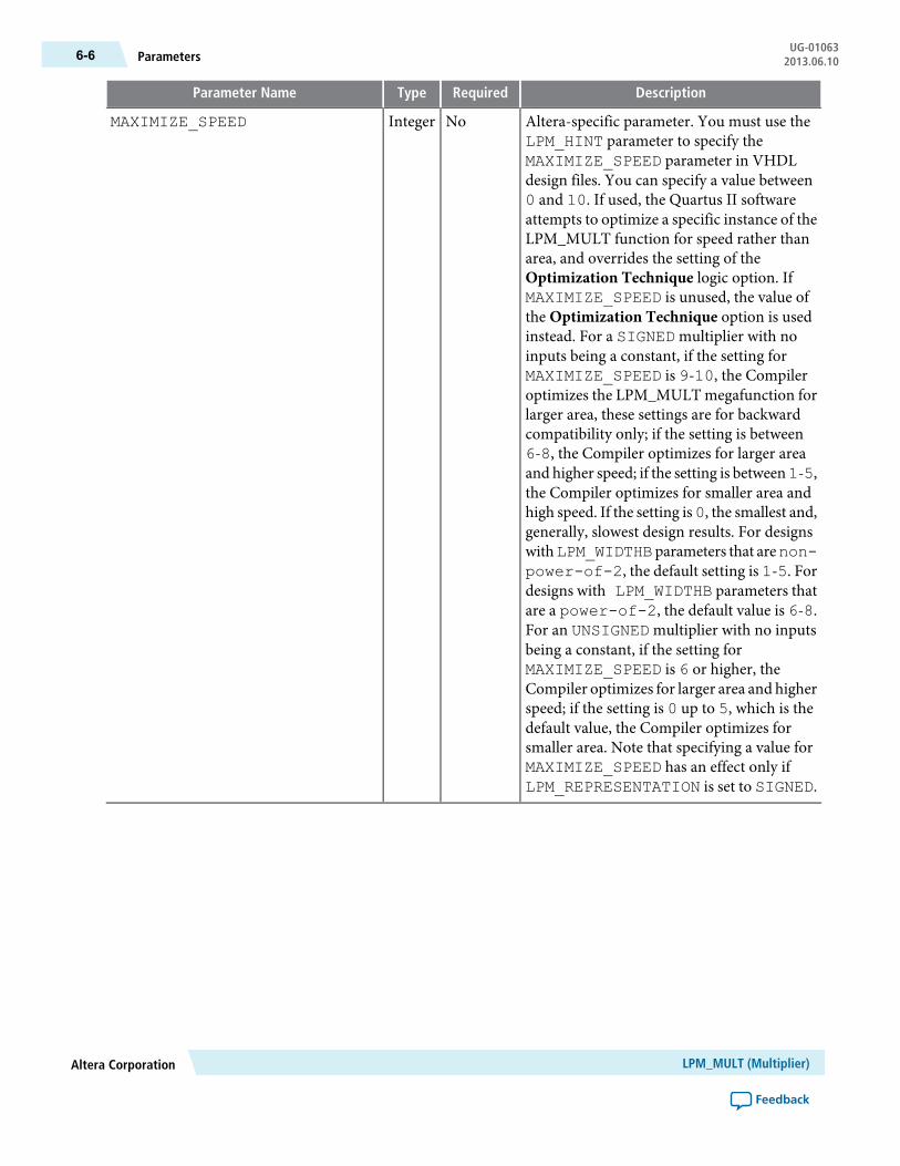
DescriptionRequiredTypeParameter Name
Altera-specific parameter. You must use theLPM_HINT parameter to specify theMAXIMIZE_SPEED parameter in VHDLdesign files. You can specify a value between0 and 10. If used, the Quartus II softwareattempts to optimize a specific instance of theLPM_MULT function for speed rather thanarea, and overrides the setting of theOptimization Technique logic option. IfMAXIMIZE_SPEED is unused, the value ofthe Optimization Technique option is usedinstead. For a SIGNEDmultiplier with noinputs being a constant, if the setting forMAXIMIZE_SPEED is 9-10, the Compileroptimizes the LPM_MULT megafunction forlarger area, these settings are for backwardcompatibility only; if the setting is between6-8, the Compiler optimizes for larger areaand higher speed; if the setting is between1-5,the Compiler optimizes for smaller area andhigh speed. If the setting is0, the smallest and,generally, slowest design results. For designswithLPM_WIDTHBparameters that arenon-power-of-2, the default setting is 1-5. Fordesigns with LPM_WIDTHB parameters thatare a power-of-2, the default value is 6-8.For an UNSIGNEDmultiplier with no inputsbeing a constant, if the setting forMAXIMIZE_SPEED is 6 or higher, theCompiler optimizes for larger area and higherspeed; if the setting is 0 up to 5, which is thedefault value, the Compiler optimizes forsmaller area. Note that specifying a value forMAXIMIZE_SPEED has an effect only ifLPM_REPRESENTATION is set to SIGNED.
NoIntegerMAXIMIZE_SPEED
LPM_MULT (Multiplier)Altera Corporation
Feedback
UG-01063Parameters6-6 2013.06.10

DescriptionRequiredTypeParameter Name
Specifies whether to use the default dedicatedmultiplier circuitry implementation. ValuesareAUTO,YES,NO, andFIRM. If omitted, thedefault value is AUTO. For Stratix and StratixGX devices, the value of AUTO specifies thatthe Quartus II software determines whetherto use the dedicated multiplier circuitry basedon the multiplier width. If a device does nothave dedicated multiplier circuitry, theDEDICATED_MULTIPLIER_CIRCUITRYparameter has no effect and the value defaultsto NO.
NoStringDEDICATED_MULTIPLIER_CIRCUITRY
Specifies whether to use a dedicatedmultipliercircuitry implementation.Values areUNUSED,AUTO, DSP BLOCKS, and LOGICELEMENTS. If omitted, the default value isUNUSED. This parameter is available for allAltera devices except Cyclone, HardCopy,MAX II, MAX 3000, and MAX 7000 devices.
NoStringDSP_BLOCK_BALANCING
Specifies whether to use a logic elementimplementation based on the selected devicefamily. When implemented in LEs, theLPM_MULT megafunction uses a variationon the Booth algorithm for all device families.Values are OFF, SIMPLE 18-BITMULTIPLIERS, SIMPLE MULTIPLIERS,WIDTH 18-BIT MULTIPLIERS, andLOGIC ELEMENTS.
NoStringLOGIC_ELEMENTS
Altera-specific parameter. You must use theLPM_HINT parameter to specify theDEDICATED_MULTIPLIER_MIN_
OUTPUT_WIDTH_FOR_AUTO parameter inVHDL design files. If the DEDICATED_MULTIPLIER_CIRCUITRY parametersetting is AUTO, this parameter specifies theminimum value of the sum of the LPM_WIDTHA and LPM_WIDTHB parameters inorder for the multiplier to be built usingdedicated circuitry.
NoIntegerDEDICATED_MULTIPLIER_
MIN_INPUT_WIDTH_FOR_AUTO
Altera CorporationLPM_MULT (Multiplier)
Feedback
6-7ParametersUG-010632013.06.10

DescriptionRequiredTypeParameter Name
Specifies the value for thedataa[] port. Thisparameter is used when the INPUT_A_IS_CONSTANT parameter is set to FIXED. Forexample, to pass a four bit value of 3 to thedataa[] port, the INPUT_A_FIXED_VALUE parameter must be set to B0011.
NoStringINPUT_A_FIXED_VALUE
Specifies the value for thedatab[] port. Thisparameter is used when the INPUT_B_IS_CONSTANT parameter is set to FIXED. Forexample, to pass a four bit value of 3 to thedatab[] port, the INPUT_B_FIXED_VALUE parameter must be set to B0011.
NoStringINPUT_B_FIXED_VALUE
LPM_MULT (Multiplier)Altera Corporation
Feedback
UG-01063Parameters6-8 2013.06.10
7ALTECC (Error Correction Code:Encoder/Decoder)
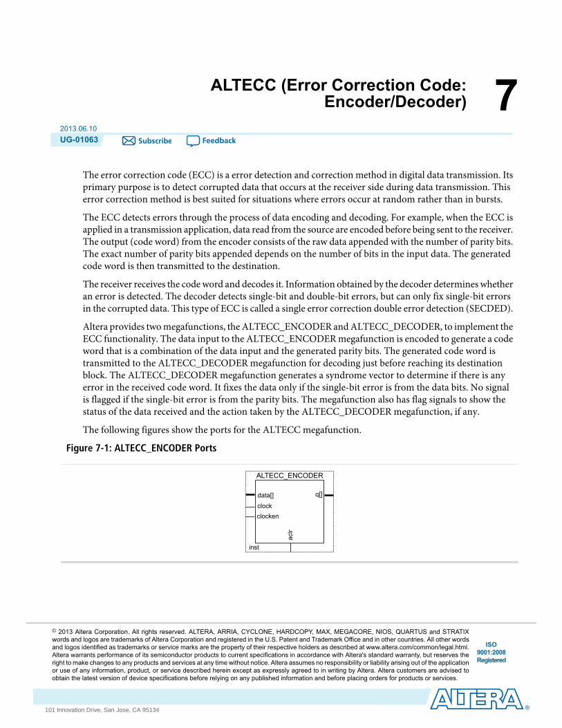
2013.06.10UG-01063 Subscribe Feedback
The error correction code (ECC) is a error detection and correction method in digital data transmission. Itsprimary purpose is to detect corrupted data that occurs at the receiver side during data transmission. Thiserror correction method is best suited for situations where errors occur at random rather than in bursts.
The ECC detects errors through the process of data encoding and decoding. For example, when the ECC isapplied in a transmission application, data read from the source are encoded before being sent to the receiver.The output (code word) from the encoder consists of the raw data appended with the number of parity bits.The exact number of parity bits appended depends on the number of bits in the input data. The generatedcode word is then transmitted to the destination.
The receiver receives the codeword and decodes it. Information obtained by the decoder determines whetheran error is detected. The decoder detects single-bit and double-bit errors, but can only fix single-bit errorsin the corrupted data. This type of ECC is called a single error correction double error detection (SECDED).
Altera provides twomegafunctions, the ALTECC_ENCODER andALTECC_DECODER, to implement theECC functionality. The data input to the ALTECC_ENCODER megafunction is encoded to generate a codeword that is a combination of the data input and the generated parity bits. The generated code word istransmitted to the ALTECC_DECODER megafunction for decoding just before reaching its destinationblock. The ALTECC_DECODER megafunction generates a syndrome vector to determine if there is anyerror in the received code word. It fixes the data only if the single-bit error is from the data bits. No signalis flagged if the single-bit error is from the parity bits. The megafunction also has flag signals to show thestatus of the data received and the action taken by the ALTECC_DECODER megafunction, if any.
The following figures show the ports for the ALTECC megafunction.
Figure 7-1: ALTECC_ENCODER Ports
data[]
inst
ALTECC_ENCODER
clockenclock
q[]
aclr
ISO9001:2008Registered
© 2013 Altera Corporation. All rights reserved. ALTERA, ARRIA, CYCLONE, HARDCOPY, MAX, MEGACORE, NIOS, QUARTUS and STRATIXwords and logos are trademarks of Altera Corporation and registered in the U.S. Patent and Trademark Office and in other countries. All other wordsand logos identified as trademarks or service marks are the property of their respective holders as described at www.altera.com/common/legal.html.Altera warrants performance of its semiconductor products to current specifications in accordance with Altera's standard warranty, but reserves theright to make changes to any products and services at any time without notice. Altera assumes no responsibility or liability arising out of the applicationor use of any information, product, or service described herein except as expressly agreed to in writing by Altera. Altera customers are advised toobtain the latest version of device specifications before relying on any published information and before placing orders for products or services.
www.altera.com
101 Innovation Drive, San Jose, CA 95134

Figure 7-2: ALTECC_DECODER Ports
data[]
inst
ALTECC_DECODER
clockenclock
q[]
aclr
err_detectederr_corrected
err_fatal
ALTECC_ENCODER FeaturesThe ALTECC_ENCODER megafunction offers the following features:
• Performs data encoding using the Hamming Coding scheme• Supports data width of 2–64 bits• Supports signed and unsigned data representation format• Support pipelining with output latency of either one or two clock cycles• Supports optional asynchronous clear and clock enable ports
TheALTECC_ENCODERmegafunction takes in and encodes the data using theHammingCoding scheme.The Hamming Coding scheme derives the parity bits and appends them to the original data to produce theoutput code word. The number of parity bits appended depends on the width of the data.
The following table lists the number of parity bits appended for different ranges of data widths. The TotalBits column represents the total number of input data bits and appended parity bits.
Table 7-1: Number of Parity Bits and Code Word According to Data Width
Total Bits (Code Word)Number of Parity BitsData Width
6-83+12-4
10-164+15-11
18-325+112-26
34-646+127-57
66-727+158-64
The parity bit derivation uses an even-parity checking. The additional 1 bit (shown in the table as +1) isappended to the parity bits as theMSBof the codeword. This ensures that the codeword has an even numberof 1’s. For example, if the data width is 4 bits, 4 parity bits are appended to the data to become a code wordwith a total of 8 bits. If 7 bits from the LSB of the 8-bit code word have an odd number of 1’s, the 8th bit(MSB) of the code word is 1 making the total number of 1’s in the code word even.
The ALTECC_ENCODER megafunction accepts only input widths of 2 to 64 bits at one time. Input widthsof 12 bits, 29 bits, and 64 bits, which are ideally suited to Altera devices, generate outputs of 18 bits, 36 bits,and 72 bits respectively. The bit-selection limitation is controlled by the MegaWizard Plug-In Manager.
ALTECC (Error Correction Code: Encoder/Decoder)Altera Corporation
Feedback
UG-01063ALTECC_ENCODER Features7-2 2013.06.10

Resource Utilization and PerformanceThe following tables provide resource utilization andperformance information for theALTECCmegafunction.
Table 7-2: ALTECC Resource Utilization and Performance for Stratix III Devices
fMAX (MHz)
Logic Usage
Outputlatency
Inputdata
widthConfiguration Adaptive Lo-
gic Module(ALM)
Dedicated Lo-gic Register
(DLR)
AdaptiveLook-Up
Table (ALUT)
1161408012
ALTECC_ENCODER
107613021029
97912019032
75827040064
118819308212
1021366520229
1013407119232
9267913639264
1161408012
ALTECC_DECODER
107613021029
97912019032
75827040064
118819308212
1021366520229
1013407119232
9267913639264
5 The performance of the megafunction is dependant on the value of the maximum allowable ceiling fMAX thatthe selected device can achieve. Therefore, results may vary from the numbers stated in this column.
Altera CorporationALTECC (Error Correction Code: Encoder/Decoder)
Feedback
7-3Resource Utilization and PerformanceUG-010632013.06.10

fMAX (MHz) 5
Logic Usage
Outputlatency
Inputdata
widthConfiguration Adaptive Logic
Module (ALM)
Dedicated Lo-gic Register
(DLR)
AdaptiveLook-Up
Table (ALUT)
1128408012
ALTECC_ENCODER
107213021029
105412019032
90127040064
110419308212
1082386520229
1061427119232
9057813639264
1128408012
ALTECC_DECODER
107213021029
105412019032
90127040064
110419308212
1082386520229
1061427119232
9057813639264
Verilog HDL Prototype (ALTECC_ENCODER)The following Verilog HDL prototype is located in the Verilog Design File (.v) lpm.v in the <Quartus IIinstallation directory>\eda\synthesis directory.
module altecc_encoder#( parameter intended_device_family = "unused",parameter lpm_pipeline = 0,parameter width_codeword = 8,parameter width_dataword = 8,parameter lpm_type = "altecc_encoder",parameter lpm_hint = "unused")( input wire aclr,input wire clock,input wire clocken,input wire [width_dataword-1:0] data,output wire [width_codeword-1:0] q);endmodule
ALTECC (Error Correction Code: Encoder/Decoder)Altera Corporation
Feedback
UG-01063Verilog HDL Prototype (ALTECC_ENCODER)7-4 2013.06.10

Verilog HDL Prototype (ALTECC_DECODER)The following Verilog HDL prototype is located in the Verilog Design File (.v) lpm.v in the <Quartus IIinstallation directory>\eda\synthesis directory.
module altecc_decoder#( parameter intended_device_family = "unused",parameter lpm_pipeline = 0,parameter width_codeword = 8,parameter width_dataword = 8,parameter lpm_type = "altecc_decoder",parameter lpm_hint = "unused")( input wire aclr,input wire clock,input wire clocken,input wire [width_codeword-1:0] data,output wire err_corrected,output wire err_detected,outut wire err_fatal,output wire [width_dataword-1:0] q);endmodule
VHDL Component Declaration (ALTECC_ENCODER)The VHDL component declaration is located in the VHDL Design File (.vhd) altera_mf_components.vhdin the <Quartus II installation directory>\libraries\vhdl\altera_mf directory.
component altecc_encodergeneric (intended_device_family:string := "unused";lpm_pipeline:natural := 0;width_codeword:natural := 8;width_dataword:natural := 8;lpm_hint:string := "UNUSED";lpm_type:string := "altecc_encoder");port(aclr:in std_logic := '0';clock:in std_logic := '0';clocken:in std_logic := '1';data:in std_logic_vector(width_dataword-1 downto 0);q:out std_logic_vector(width_codeword-1 downto 0));end component;
Altera CorporationALTECC (Error Correction Code: Encoder/Decoder)
Feedback
7-5Verilog HDL Prototype (ALTECC_DECODER)UG-010632013.06.10
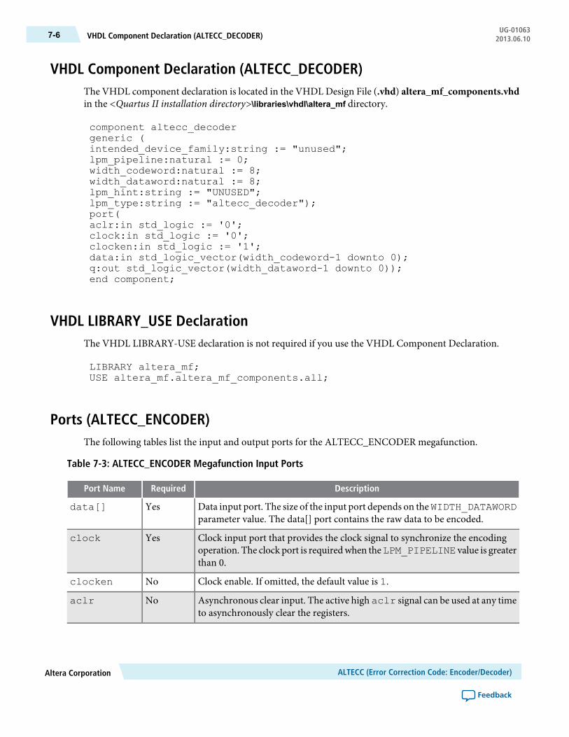
VHDL Component Declaration (ALTECC_DECODER)The VHDL component declaration is located in the VHDL Design File (.vhd) altera_mf_components.vhdin the <Quartus II installation directory>\libraries\vhdl\altera_mf directory.
component altecc_decodergeneric (intended_device_family:string := "unused";lpm_pipeline:natural := 0;width_codeword:natural := 8;width_dataword:natural := 8;lpm_hint:string := "UNUSED";lpm_type:string := "altecc_decoder");port(aclr:in std_logic := '0';clock:in std_logic := '0';clocken:in std_logic := '1';data:in std_logic_vector(width_codeword-1 downto 0);q:out std_logic_vector(width_dataword-1 downto 0));end component;
VHDL LIBRARY_USE DeclarationThe VHDL LIBRARY-USE declaration is not required if you use the VHDL Component Declaration.
LIBRARY altera_mf;USE altera_mf.altera_mf_components.all;
Ports (ALTECC_ENCODER)The following tables list the input and output ports for the ALTECC_ENCODER megafunction.
Table 7-3: ALTECC_ENCODER Megafunction Input Ports
DescriptionRequiredPort Name
Data input port. The size of the input port depends on theWIDTH_DATAWORDparameter value. The data[] port contains the raw data to be encoded.
Yesdata[]
Clock input port that provides the clock signal to synchronize the encodingoperation. The clock port is requiredwhen theLPM_PIPELINE value is greaterthan 0.
Yesclock
Clock enable. If omitted, the default value is 1.Noclocken
Asynchronous clear input. The active highaclr signal can be used at any timeto asynchronously clear the registers.
Noaclr
ALTECC (Error Correction Code: Encoder/Decoder)Altera Corporation
Feedback
UG-01063VHDL Component Declaration (ALTECC_DECODER)7-6 2013.06.10
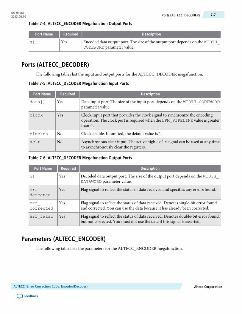
Table 7-4: ALTECC_ENCODER Megafunction Output Ports
DescriptionRequiredPort Name
Encoded data output port. The size of the output port depends on the WIDTH_CODEWORD parameter value.
Yesq[]
Ports (ALTECC_DECODER)The following tables list the input and output ports for the ALTECC_DECODER megafunction.
Table 7-5: ALTECC_DECODER Megafunction Input Ports
DescriptionRequiredPort Name
Data input port. The size of the input port depends on the WIDTH_CODEWORDparameter value.
Yesdata[]
Clock input port that provides the clock signal to synchronize the encodingoperation. The clock port is required when the LPM_PIPELINE value is greaterthan 0.
Yesclock
Clock enable. If omitted, the default value is 1.Noclocken
Asynchronous clear input. The active high aclr signal can be used at any timeto asynchronously clear the registers.
Noaclr
Table 7-6: ALTECC_DECODER Megafunction Output Ports
DescriptionRequiredPort Name
Decoded data output port. The size of the output port depends on the WIDTH_DATAWORD parameter value.
Yesq[]
Flag signal to reflect the status of data received and specifies any errors found.Yeserr_detected
Flag signal to reflect the status of data received. Denotes single-bit error foundand corrected. You can use the data because it has already been corrected.
Yeserr_corrected
Flag signal to reflect the status of data received. Denotes double-bit error found,but not corrected. You must not use the data if this signal is asserted.
Yeserr_fatal
Parameters (ALTECC_ENCODER)The following table lists the parameters for the ALTECC_ENCODER megafunction.
Altera CorporationALTECC (Error Correction Code: Encoder/Decoder)
Feedback
7-7Ports (ALTECC_DECODER)UG-010632013.06.10

Table 7-7: ALTECC_ENCODER Megafunction Parameters
DescriptionRequiredTypeParameter Name
Specifies the width of the raw data. Values are from2 to64.If omitted, the default value is 8.
YesIntegerWIDTH_DATAWORD
Specifies the width of the corresponding code word. Validvalues are from 6 to 72, excluding 9, 17, 33, and 65. Ifomitted, the default value is 13.
YesIntegerWIDTH_CODEWORD
Specifies the pipeline for the circuit. Values are from 0 to2. If the value is 0, the ports are not registered. If the valueis 1, the output ports are registered. If the value is 2, theinput and output ports are registered. If omitted, the defaultvalue is 0.
NoIntegerLPM_PIPELINE
Parameters (ALTECC_DECODER)The following table lists the parameters for the ALTECC_DECODER megafunction.
Table 7-8: ALTECC_DECODER Megafunction Parameters
DescriptionRequiredTypeParameter Name
Specifies the width of the raw data. Values are 2 to 64. Thedefault value is 8.
YesIntegerWIDTH_DATAWORD
Specifies the width of the corresponding code word. Valuesare 6 to 72, excluding 9, 17, 33, and 65. If omitted, thedefault value is 13.
YesIntegerWIDTH_CODEWORD
Specifies the register of the circuit. Values are from 0 to 2.If the value is 0, no register is implemented. If the value is1, the output is registered. If the value is 2, both the inputand the output are registered. If the value is greater than 2,additional registers are implemented at the output for theadditional latencies. If omitted, the default value is 0.
NoIntegerLPM_PIPELINE
Design Example 1: ALTECC_ENCODERThis design example uses the ECC encoder to encode an 8-bit wide input data to generate 13 bits of outputcode word. This example uses the MegaWizard Plug-In Manager in the Quartus II software.
The following design files can be found in altecc_DesignExample1.zip:
• altecc_encode.qar (archived Quartus II design files)• altecc_encode_ex_msim (ModelSim-Altera files)
ALTECC (Error Correction Code: Encoder/Decoder)Altera Corporation
Feedback
UG-01063Parameters (ALTECC_DECODER)7-8 2013.06.10

Understanding the Simulation ResultsThe following settings are observed in this example:
• The data[] input width is set to 8 bits• The output port, q[] has a width of 13 bits• The clock enable (clocken) signal is enabled• Pipelining is enabled, with an output latency of 2 clock cycles. Hence, the result is seen on the q[] port
two clock cycles after the input data is available
The following figure shows the expected simulation results in the ModelSim-Altera software.
Figure 7-3: Design Example 1: Simulation Waveform for the ECC Encoder
Altera CorporationALTECC (Error Correction Code: Encoder/Decoder)
Feedback
7-9Understanding the Simulation ResultsUG-010632013.06.10

The following sequence corresponds with the numbered items in the figure:
ALTECC (Error Correction Code: Encoder/Decoder)Altera Corporation
Feedback
UG-01063Understanding the Simulation Results7-10 2013.06.10
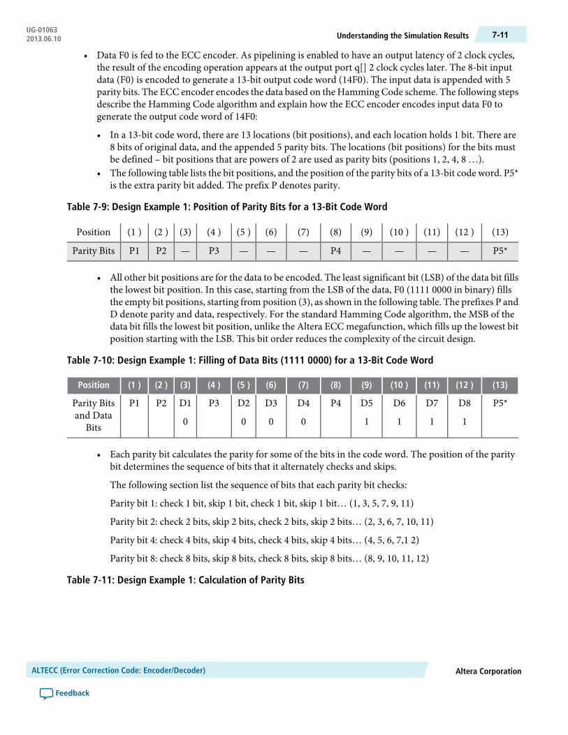
• Data F0 is fed to the ECC encoder. As pipelining is enabled to have an output latency of 2 clock cycles,the result of the encoding operation appears at the output port q[] 2 clock cycles later. The 8-bit inputdata (F0) is encoded to generate a 13-bit output code word (14F0). The input data is appended with 5parity bits. The ECC encoder encodes the data based on the Hamming Code scheme. The following stepsdescribe the Hamming Code algorithm and explain how the ECC encoder encodes input data F0 togenerate the output code word of 14F0:
• In a 13-bit code word, there are 13 locations (bit positions), and each location holds 1 bit. There are8 bits of original data, and the appended 5 parity bits. The locations (bit positions) for the bits mustbe defined – bit positions that are powers of 2 are used as parity bits (positions 1, 2, 4, 8 …).
• The following table lists the bit positions, and the position of the parity bits of a 13-bit code word. P5*is the extra parity bit added. The prefix P denotes parity.
Table 7-9: Design Example 1: Position of Parity Bits for a 13-Bit Code Word
(13)(12 )(11)(10 )(9)(8)(7)(6)(5 )(4 )(3)(2 )(1 )Position
P5*————P4———P3—P2P1Parity Bits
• All other bit positions are for the data to be encoded. The least significant bit (LSB) of the data bit fillsthe lowest bit position. In this case, starting from the LSB of the data, F0 (1111 0000 in binary) fillsthe empty bit positions, starting from position (3), as shown in the following table. The prefixes P andD denote parity and data, respectively. For the standard Hamming Code algorithm, the MSB of thedata bit fills the lowest bit position, unlike the Altera ECC megafunction, which fills up the lowest bitposition starting with the LSB. This bit order reduces the complexity of the circuit design.
Table 7-10: Design Example 1: Filling of Data Bits (1111 0000) for a 13-Bit Code Word
(13)(12 )(11)(10 )(9)(8)(7)(6)(5 )(4 )(3)(2 )(1 )Position
P5*D8
1
D7
1
D6
1
D5
1
P4D4
0
D3
0
D2
0
P3D1
0
P2P1Parity Bitsand Data
Bits
• Each parity bit calculates the parity for some of the bits in the code word. The position of the paritybit determines the sequence of bits that it alternately checks and skips.
The following section list the sequence of bits that each parity bit checks:
Parity bit 1: check 1 bit, skip 1 bit, check 1 bit, skip 1 bit… (1, 3, 5, 7, 9, 11)
Parity bit 2: check 2 bits, skip 2 bits, check 2 bits, skip 2 bits… (2, 3, 6, 7, 10, 11)
Parity bit 4: check 4 bits, skip 4 bits, check 4 bits, skip 4 bits… (4, 5, 6, 7,1 2)
Parity bit 8: check 8 bits, skip 8 bits, check 8 bits, skip 8 bits… (8, 9, 10, 11, 12)
Table 7-11: Design Example 1: Calculation of Parity Bits
Altera CorporationALTECC (Error Correction Code: Encoder/Decoder)
Feedback
7-11Understanding the Simulation ResultsUG-010632013.06.10
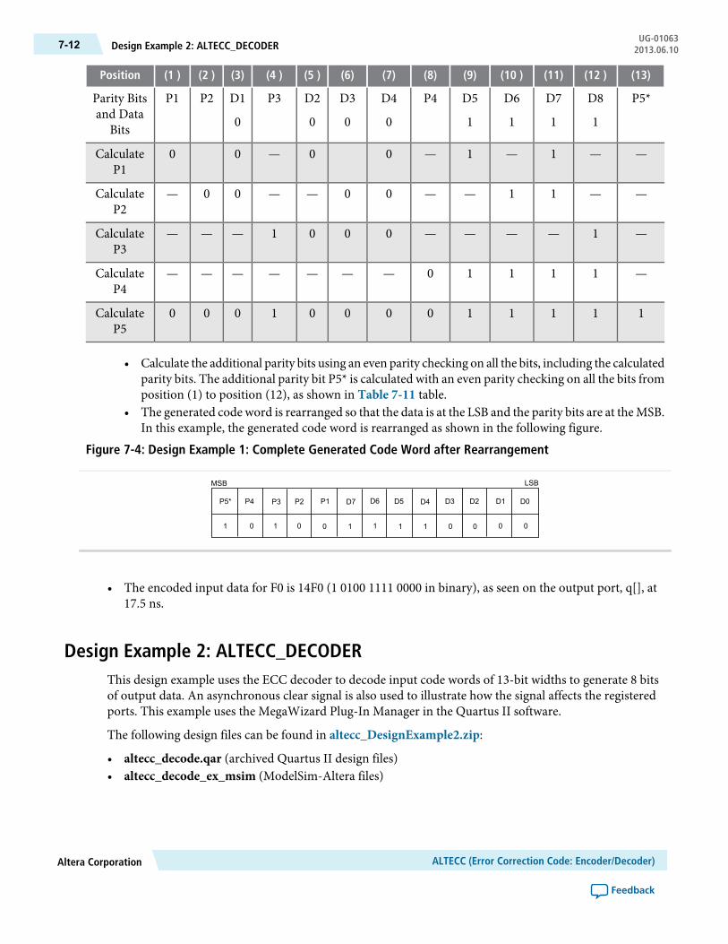
(13)(12 )(11)(10 )(9)(8)(7)(6)(5 )(4 )(3)(2 )(1 )Position
P5*D8
1
D7
1
D6
1
D5
1
P4D4
0
D3
0
D2
0
P3D1
0
P2P1Parity Bitsand Data
Bits
——1—1—00—00CalculateP1
——11——00——00—CalculateP2
—1————0001———CalculateP3
—11110———————CalculateP4
1111100001000CalculateP5
• Calculate the additional parity bits using an even parity checking on all the bits, including the calculatedparity bits. The additional parity bit P5* is calculated with an even parity checking on all the bits fromposition (1) to position (12), as shown in Table 7-11 table.
• The generated code word is rearranged so that the data is at the LSB and the parity bits are at the MSB.In this example, the generated code word is rearranged as shown in the following figure.
Figure 7-4: Design Example 1: Complete Generated Code Word after Rearrangement
P5*
MSB LSB
1
P4 P3 P2 P1 D7 D6 D5 D4 D3 D2 D1 D0
0 1 0 0 1 1 1 1 0 0 0 0
• The encoded input data for F0 is 14F0 (1 0100 1111 0000 in binary), as seen on the output port, q[], at17.5 ns.
Design Example 2: ALTECC_DECODERThis design example uses the ECC decoder to decode input code words of 13-bit widths to generate 8 bitsof output data. An asynchronous clear signal is also used to illustrate how the signal affects the registeredports. This example uses the MegaWizard Plug-In Manager in the Quartus II software.
The following design files can be found in altecc_DesignExample2.zip:
• altecc_decode.qar (archived Quartus II design files)• altecc_decode_ex_msim (ModelSim-Altera files)
ALTECC (Error Correction Code: Encoder/Decoder)Altera Corporation
Feedback
UG-01063Design Example 2: ALTECC_DECODER7-12 2013.06.10
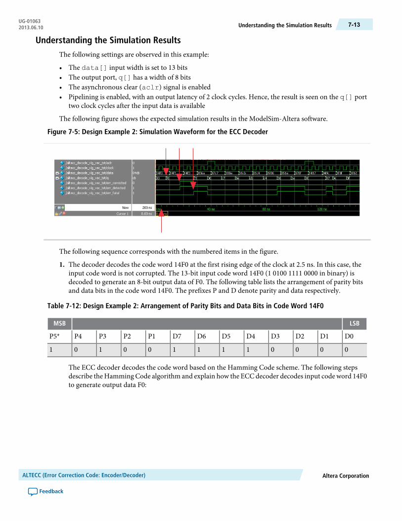
Understanding the Simulation ResultsThe following settings are observed in this example:
• The data[] input width is set to 13 bits• The output port, q[] has a width of 8 bits• The asynchronous clear (aclr) signal is enabled• Pipelining is enabled, with an output latency of 2 clock cycles. Hence, the result is seen on the q[] port
two clock cycles after the input data is available
The following figure shows the expected simulation results in the ModelSim-Altera software.
Figure 7-5: Design Example 2: Simulation Waveform for the ECC Decoder
The following sequence corresponds with the numbered items in the figure.
1. The decoder decodes the code word 14F0 at the first rising edge of the clock at 2.5 ns. In this case, theinput code word is not corrupted. The 13-bit input code word 14F0 (1 0100 1111 0000 in binary) isdecoded to generate an 8-bit output data of F0. The following table lists the arrangement of parity bitsand data bits in the code word 14F0. The prefixes P and D denote parity and data respectively.
Table 7-12: Design Example 2: Arrangement of Parity Bits and Data Bits in Code Word 14F0
LSBMSB
D0D1D2D3D4D5D6D7P1P2P3P4P5*
0000111100101
The ECC decoder decodes the code word based on the Hamming Code scheme. The following stepsdescribe the Hamming Code algorithm and explain how the ECC decoder decodes input code word 14F0to generate output data F0:
Altera CorporationALTECC (Error Correction Code: Encoder/Decoder)
Feedback
7-13Understanding the Simulation ResultsUG-010632013.06.10
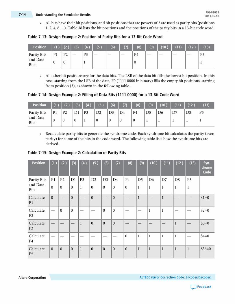
• All bits have their bit positions, and bit positions that are powers of 2 are used as parity bits (positions1, 2, 4, 8 …). Table 38 lists the bit positions and the positions of the parity bits in a 13-bit code word.
Table 7-13: Design Example 2: Position of Parity Bits for a 13-Bit Code Word
(13)(12 )(11)(10 )(9)(8)(7)(6)(5 )(4 )(3)(2 )(1 )Position
P5
1
————P4
0
———P3
1
—P2
0
P1
0
Parity Bitsand DataBits
• All other bit positions are for the data bits. The LSB of the data bit fills the lowest bit position. In thiscase, starting from the LSB of the data, F0 (1111 0000 in binary) fills the empty bit positions, startingfrom position (3), as shown in the following table.
Table 7-14: Design Example 2: Filling of Data Bits (1111 0000) for a 13-Bit Code Word
(13)(12 )(11)(10 )(9)(8)(7)(6)(5 )(4 )(3)(2 )(1 )Position
P5
1
D8
1
D7
1
D6
1
D5
1
P4
0
D4
0
D3
0
D2
0
P3
1
D1
0
P2
0
P1
0
Parity Bitsand DataBits
• Recalculate parity bits to generate the syndrome code. Each syndrome bit calculates the parity (evenparity) for some of the bits in the code word. The following table lists how the syndrome bits arederived.
Table 7-15: Design Example 2: Calculation of Parity Bits
Syn-dromeCode
(13)(12 )(11)(10 )(9)(8)(7)(6)(5 )(4 )(3)(2 )(1 )Position
P5
1
D8
1
D7
1
D6
1
D5
1
P4
0
D4
0
D3
0
D2
0
P3
1
D1
0
P2
0
P1
0
Parity Bitsand DataBits
S1=0——1—1—0—0—0—0CalculateP1
S2=0——11——00——00—CalculateP2
S3=0—1————0001———CalculateP3
S4=0—11110———————CalculateP4
S5*=01111100001000CalculateP5
ALTECC (Error Correction Code: Encoder/Decoder)Altera Corporation
Feedback
UG-01063Understanding the Simulation Results7-14 2013.06.10
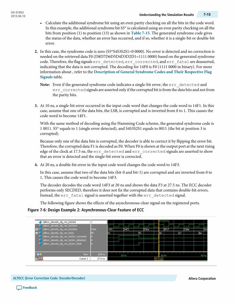
• Calculate the additional syndrome bit using an even parity checking on all the bits in the code word.In this example, the additional syndrome bit S5* is calculated using an even parity checking on all thebits from position (1) to position (13) as shown in Table 7-15. The generated syndrome code givesthe status of the data, whether an error has occurred, and if so, whether it is a single-bit or double-biterror.
2. In this case, the syndrome code is zero (S5*S4S3S2S1=0 0000). No error is detected and no correction isneeded on the retrieved data F0 (D8D7D6D5D4D3D2D1=1111 0000) based on the generated syndromecode. Therefore, the flag signalserr_detected,err_corrected, anderr_fatal are deasserted,indicating that the data is not corrupted. The decoding for 14F0 is F0 (1111 0000 in binary). For moreinformation about , refer to the Description of General Syndrome Codes and Their Respective FlagSignals table.
Even if the generated syndrome code indicates a single-bit error, the err_detected anderr_corrected signals are asserted only if the corrupted bit is from the data bits and not fromthe parity bits.
Note:
3. At 10 ns, a single-bit error occurred in the input code word that changes the code word to 14F1. In thiscase, assume that one of the data bits, the LSB, is corrupted and is inverted from 0 to 1. This causes thecode word to become 14F1.
With the same method of decoding using the Hamming Code scheme, the generated syndrome code is1 0011. S5* equals to 1 (single error detected), and S4S3S2S1 equals to 0011 (the bit at position 3 iscorrupted).
Because only one of the data bits is corrupted, the decoder is able to correct it by flipping the error bit.Therefore, the corrupted data F1 is decoded as F0. When F0 is shown at the output port at the next risingedge of the clock at 17.5 ns, the err_detected and err_corrected signals are asserted to showthat an error is detected and the single-bit error is corrected.
4. At 20 ns, a double-bit error in the input code word changes the code word to 14F3.
In this case, assume that two of the data bits (bit-0 and bit-1) are corrupted and are inverted from 0 to1. This causes the code word to become 14F3.
The decoder decodes the code word 14F3 at 20 ns and shows the data F3 at 27.5 ns. The ECC decoderperforms only SECDED, therefore it does not fix the corrupted data that contains double-bit errors.Instead, the err_fatal signal is asserted together with the err_detected signal.
The following figure shows the effects of the asynchronous-clear signal on the registered ports.
Figure 7-6: Design Example 2: Asynchronous-Clear Feature of ECC
Altera CorporationALTECC (Error Correction Code: Encoder/Decoder)
Feedback
7-15Understanding the Simulation ResultsUG-010632013.06.10

This figure shows that when the aclr signal is asserted at 37.5 ns, the output and status signals arecleared immediately.
If you do not want to use the corrupted data when the err_fatal signal is asserted, you can assert theasynchronous-clear signal (aclr) to clear the output port q and other status signals that are registered.You must enable the pipelining option in the MegaWizard Plug-In Manager to use this feature.
ALTECC (Error Correction Code: Encoder/Decoder)Altera Corporation
Feedback
UG-01063Understanding the Simulation Results7-16 2013.06.10

8ALTERA_MULT_ADD (Multiply-Adder)
2013.06.10UG-01063 Subscribe Feedback
The ALTERA_MULT_ADD megafunction allows you to implement a multiplier-adder.
The following figure shows the ports for the ALTERA_MULT_ADD megafunction.
Figure 8-1: ALTERA_MULT_ADD Ports
dataa[]
inst
ALTERA_MULT_ADD
datab[]signa scanouta[]
signbresult[]
datac[]
coefsel1[]
addnsub1addnsub3
clock0
ena0
accum_sloadchainin[]
coefsel2[]coefsel3[]
coefsel0[]
aclr[]scanina[]
sload_accum
clock1clock2
ena1ena2
aclr0
aclr1
A multiplier-adder accepts pairs of inputs, multiplies the values together and then adds to or subtracts fromthe products of all other pairs.
The ALTERA_MULT_ADD megafunction also offers many variations in dedicated DSP block circuitry.Data input sizes of up to 18 bits are accepted. Because the DSP blocks allow for one or two levels of 2-inputadd or subtract operations on the product, this function creates up to four multipliers.
The multiplier blocks and adder/accumulator block is combined in a single MAC block.
The multipliers and adders of the ALTERA_MULT_ADD megafunction are placed in the dedicated DSPblock circuitry of the Stratix devices. If all of the input data widths are 9-bits wide or smaller, the functionuses the 9 × 9-bit input multiplier configuration in the DSP block. If not, the DSP block uses 18 × 18-bit
ISO9001:2008Registered
© 2013 Altera Corporation. All rights reserved. ALTERA, ARRIA, CYCLONE, HARDCOPY, MAX, MEGACORE, NIOS, QUARTUS and STRATIXwords and logos are trademarks of Altera Corporation and registered in the U.S. Patent and Trademark Office and in other countries. All other wordsand logos identified as trademarks or service marks are the property of their respective holders as described at www.altera.com/common/legal.html.Altera warrants performance of its semiconductor products to current specifications in accordance with Altera's standard warranty, but reserves theright to make changes to any products and services at any time without notice. Altera assumes no responsibility or liability arising out of the applicationor use of any information, product, or service described herein except as expressly agreed to in writing by Altera. Altera customers are advised toobtain the latest version of device specifications before relying on any published information and before placing orders for products or services.
www.altera.com
101 Innovation Drive, San Jose, CA 95134

inputmultipliers to process datawithwidths between 10 bits and 18 bits. Ifmultiple ALTERA_MULT_ADDmegafunctions occur in a design, the functions are distributed to as many different DSP blocks as possibleso that routing to these blocks is more flexible. Fewer multipliers per DSP block allow more routing choicesinto the block by minimizing paths to the rest of the device.
The registers and extra pipeline registers for the following signals are also placed inside the DSP block:
• Data input• Signed or unsigned select• Add or subtract select• Products of multipliers
In the case of the output result, the first register is placed in theDSP block. However the extra latency registersare placed in logic elements outside the block. Peripheral to the DSP block, including data inputs to themultiplier, control signal inputs, and outputs of the adder, use regular routing to communicate with the restof the device. All connections in the function use dedicated routing inside the DSP block. This dedicatedrouting includes the shift register chains when you select the option to shift a multiplier's registered inputdata from one multiplier to an adjacent multiplier.
For more information about DSP blocks in any of the Stratix, Stratix GX, and Arria GX device series, referto the DSP Blocks chapter of the respective handbooks on the Literature and Technical Documentationpage.
For more information about the embedded memory blocks in any of the Stratix, Stratix GX, and Arria GXdevice series, refer to the TriMatrix Embedded Memory Blocks chapter of the respective handbooks on theLiterature and Technical Documentation page.
For more information on embedded multiplier blocks in the Cyclone II and Cyclone III devices, refer to theDSP Blocks chapter of the respective handbooks on the Literature and Technical Documentation page.
For more information about implementing multipliers using DSP and memory blocks in Altera FPGAs,refer to AN 306: Implementing Multipliers in FPGA Devices.
FeaturesThe ALTERA_MULT_ADD megafunction offers the following features:
• Generates a multiplier to perform multiplication operations of two complex numbers• Supports data widths of 1– 256 bits• Supports signed and unsigned data representation format• Supports pipelining with configurable output latency• Provides an option to dynamically switch between signed and unsigned data support• Provides an option to dynamically switch between add and subtract operation• Supports optional asynchronous clear and clock enable input ports• Supports systolic delay register mode• Supports pre-adder with 8 pre-load coefficients per multiplier• Supports pre-load constant to complement accumulator feedback• Pre-adder, coefficient storage and systolic delay register features are added to maximize flexibility.
ALTERA_MULT_ADD (Multiply-Adder)Altera Corporation
Feedback
UG-01063Features8-2 2013.06.10
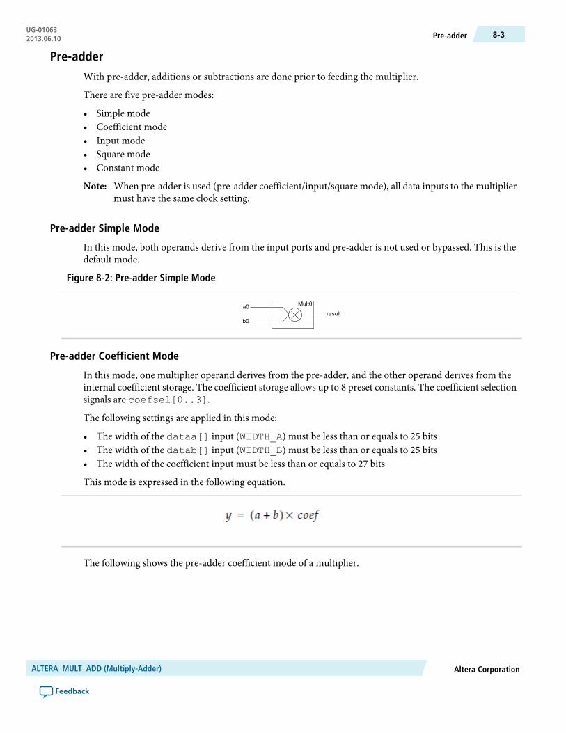
Pre-adderWith pre-adder, additions or subtractions are done prior to feeding the multiplier.
There are five pre-adder modes:
• Simple mode• Coefficient mode• Input mode• Square mode• Constant mode
When pre-adder is used (pre-adder coefficient/input/square mode), all data inputs to the multipliermust have the same clock setting.
Note:
Pre-adder Simple Mode
In this mode, both operands derive from the input ports and pre-adder is not used or bypassed. This is thedefault mode.
Figure 8-2: Pre-adder Simple Mode
a0
b0
Mult0
result
Pre-adder Coefficient Mode
In this mode, one multiplier operand derives from the pre-adder, and the other operand derives from theinternal coefficient storage. The coefficient storage allows up to 8 preset constants. The coefficient selectionsignals are coefsel[0..3].
The following settings are applied in this mode:
• The width of the dataa[] input (WIDTH_A) must be less than or equals to 25 bits• The width of the datab[] input (WIDTH_B) must be less than or equals to 25 bits• The width of the coefficient input must be less than or equals to 27 bits
This mode is expressed in the following equation.
The following shows the pre-adder coefficient mode of a multiplier.
Altera CorporationALTERA_MULT_ADD (Multiply-Adder)
Feedback
8-3Pre-adderUG-010632013.06.10
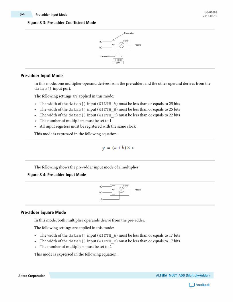
Figure 8-3: Pre-adder Coefficient Mode
a0
b0
Mult0
result
coef
+/-
Preadder
coefsel0
Pre-adder Input Mode
In this mode, one multiplier operand derives from the pre-adder, and the other operand derives from thedatac[] input port.
The following settings are applied in this mode:
• The width of the dataa[] input (WIDTH_A) must be less than or equals to 25 bits• The width of the datab[] input (WIDTH_B) must be less than or equals to 25 bits• The width of the datac[] input (WIDTH_C) must be less than or equals to 22 bits• The number of multipliers must be set to 1• All input registers must be registered with the same clock
This mode is expressed in the following equation.
The following shows the pre-adder input mode of a multiplier.
Figure 8-4: Pre-adder Input Mode
a0
b0
Mult0
result
c0
+/-
Pre-adder Square Mode
In this mode, both multiplier operands derive from the pre-adder.
The following settings are applied in this mode:
• The width of the dataa[] input (WIDTH_A) must be less than or equals to 17 bits• The width of the datab[] input (WIDTH_B) must be less than or equals to 17 bits• The number of multipliers must be set to 2
This mode is expressed in the following equation.
ALTERA_MULT_ADD (Multiply-Adder)Altera Corporation
Feedback
UG-01063Pre-adder Input Mode8-4 2013.06.10

The following shows the pre-adder square mode of two multipliers.
Figure 8-5: Pre-adder Square Mode
a0
b0
a1
b1
Mult0
Mult1result
+/-
+/-
Pre-adder Constant Mode
In this mode, one multiplier operand derives from the input port, and the other operand derives from theinternal coefficient storage. The coefficient storage allows up to 8 preset constants. The coefficient selectionsignals are coefsel[0..3].
The following settings are applied in this mode:
• The width of the dataa[] input (WIDTH_A) must be less than or equals to 27 bits• The width of the coefficient input must be less than or equals to 27 bits• The datab[] port must be disconnected
This mode is expressed in the following equation.
The following figure shows the pre-adder constant mode of a multiplier.
Figure 8-6: Pre-adder Constant Mode
a0
Mult0
result
coef
coefsel0
Systolic Delay RegisterIn a systolic architecture, the input data is fed into a cascade of registers acting as a data buffer. Each registerdelivers an input sample to a multiplier where it is multiplied by the respective coefficient. The chain adderstores the gradually combined results from the multiplier and the previously registered result from thechainin[] input port to form the final result. Each multiply-add element must be delayed by a single
Altera CorporationALTERA_MULT_ADD (Multiply-Adder)
Feedback
8-5Pre-adder Constant ModeUG-010632013.06.10

cycle so that the results synchronize appropriately when added together. Each successive delay is used toaddress both the coefficient memory and the data buffer of their respective multiply-add elements. Forexample, a single delay for the second multiply add element, two delays for the third multiply-add element,and so on.
Figure 8-7: Systolic Registers
x(t)
c(0) c(1) c(2)
y(t)
c(N-1)
Systolic registers
S-1 S-1 S-1 S-1 S-1 S-1
S-1 S-1 S-1S-1
x(t) represents the results from a continuous stream of input samples and y(t) represents the summation ofa set of input samples, and in time, multiplied by their respective coefficients. Both the input and outputresults flow from left to right. The c(0) to c(N-1) denotes the coefficients. The systolic delay registers aredenoted by S-1, whereas the –1 represents a single clock delay. Systolic delay registers are added at the inputsand outputs for pipelining in away that ensures the results from themultiplier operand and the accumulatedsums stay in synch. This processing element is replicated to form a circuit that computes the filtering function.This function is expressed in the following equation.
N represents the number of cycles of data that has entered into the accumulator, y(t) represents the outputat time t,A(t) represents the input at time t, andB(i) are the coefficients. The t and i in the equation correspondto a particular instant in time, so to compute the output sample y(t) at time t, a group of input samples at Ndifferent points in time, or A(n), A(n-1), A(n-2), … A(n-N+1) is required. The group of N input samplesare multiplied by N coefficients and summed together to form the final result y.
The systolic register architecture is available only for sum-of-2 and sum-of-4 modes.
The following figure shows the systolic delay register implementation of 2 multipliers.
ALTERA_MULT_ADD (Multiply-Adder)Altera Corporation
Feedback
UG-01063Systolic Delay Register8-6 2013.06.10

Figure 8-8: Systolic Delay Register Implementation of 2 Multipliers
a0
b0
Mult0
result
chainin
a1
b1
Mult1
+/-
+/-
Systolic registers
The sum of two multipliers is expressed in the following equation.
The following figure shows the systolic delay register implementation of 4 multipliers.
Altera CorporationALTERA_MULT_ADD (Multiply-Adder)
Feedback
8-7Systolic Delay RegisterUG-010632013.06.10

Figure 8-9: Systolic Delay Register Implementation of 4 Multipliers
a0
b0
Mult0
result
chainin
chainin
a1
b1
Mult1
a2
b2
Mult2
a3
b3
Mult3
result
+/-
+/-
+/-
+/-
Systolic registers
The sum of four multipliers is expressed in the following equation.
Figure 8-10: Sum of 4 Multipliers
The following lists the advantages of systolic register implementation:
• Reduces DSP resource usage• Enables efficient mapping in the DSP block using the chain adder structure
The systolic delay implementation is only available for the following pre-adder modes:
• Pre-adder coefficient mode• Pre-adder simple mode• Pre-adder constant mode
ALTERA_MULT_ADD (Multiply-Adder)Altera Corporation
Feedback
UG-01063Systolic Delay Register8-8 2013.06.10

Pre-load ConstantThe pre-load constant controls the accumulator operand and complements the accumulator feedback. Thevalid LOADCONST_VALUE ranges from 0–64. The constant value is equal to 2N, where N =LOADCONST_VALUE. When the LOADCONST_VALUE is set to 64, the constant value is equal to 0. Thisfunction can be used as biased rounding.
The following figure shows the pre-load constant implementation.
Figure 8-11: Pre-load Constant
a0
b0
a1
b1
Mult0
Mult1
Accumulator feedback
accum_sload
constant
result
+/-
+/-
Refer to the following megafunctions in this user guide for other multiplier implementations:
• ALTMULT_ACCUM (Multiply-Accumulate)• ALTMEMMULT (Memory-based Constant Coefficient Multiplier)• LPM_MULT (Multiplier)
Double AccumulatorThe double accumulator feature adds an additional register in the accumulator feedback path. The doubleaccumulator register follows the output register, which includes the clock, clock enable, and aclr. Theadditional accumulator register returns result with a one-cycle delay. This feature enables you to have twoaccumulator channels with the same resource count.
The following figure shows the double accumulator implementation.
Altera CorporationALTERA_MULT_ADD (Multiply-Adder)
Feedback
8-9Pre-load ConstantUG-010632013.06.10

Figure 8-12: Double Accumulator
a0
b0
a1
b1
Mult0
Mult1
Accumulator feedback
Output result
+/-
+/-
Double Accumulator Register
Output Register
Verilog HDL PrototypeThe followingVerilogHDLprototype is located in theVerilogDesign File (.v) in the<Quartus II installationdirectory>\eda\synthesis directory.
VHDL Component DeclarationThe VHDL component declaration is located in the VHDL Design File (.vhd) in the<Quartus II installationdirectory> directory.
VHDL LIBRARY_USE DeclarationThe VHDL LIBRARY-USE declaration is not required if you use the VHDL Component Declaration.
LIBRARY altera_lnsim;USE altera_lnsim.altera_lnsim_components.all;
PortsThe following tables list the input and output ports of the ALTERA_MULT_ADD megafunction.
Table 8-1: ALTERA_MULT_ADD MegaFunction Input Ports
DescriptionRequiredPort name
Data input to the multiplier. Input port [NUMBER_OF_MULTIPLIERS* WIDTH_A - 1 … 0] wide
Yesdataa []
Data input to the multiplier. Input port [NUMBER_OF_MULTIPLIERS* WIDTH_B - 1 … 0] wide
Yesdatab []
ALTERA_MULT_ADD (Multiply-Adder)Altera Corporation
Feedback
UG-01063Verilog HDL Prototype8-10 2013.06.10
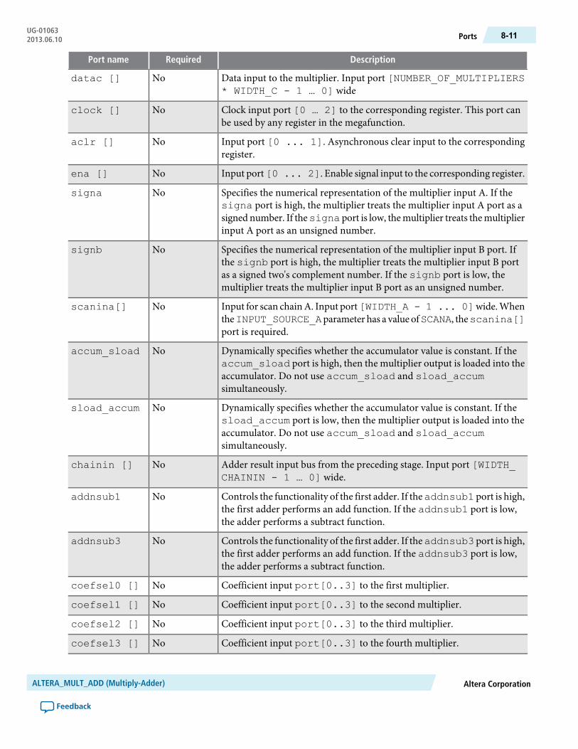
DescriptionRequiredPort name
Data input to the multiplier. Input port [NUMBER_OF_MULTIPLIERS* WIDTH_C - 1 … 0] wide
Nodatac []
Clock input port [0 … 2] to the corresponding register. This port canbe used by any register in the megafunction.
Noclock []
Input port [0 ... 1]. Asynchronous clear input to the correspondingregister.
Noaclr []
Input port[0 ... 2]. Enable signal input to the corresponding register.Noena []
Specifies the numerical representation of the multiplier input A. If thesigna port is high, the multiplier treats the multiplier input A port as asigned number. If thesigna port is low, themultiplier treats themultiplierinput A port as an unsigned number.
Nosigna
Specifies the numerical representation of the multiplier input B port. Ifthe signb port is high, the multiplier treats the multiplier input B portas a signed two's complement number. If the signb port is low, themultiplier treats the multiplier input B port as an unsigned number.
Nosignb
Input for scan chainA. Input port[WIDTH_A - 1 ... 0]wide.WhentheINPUT_SOURCE_Aparameter has a value ofSCANA, thescanina[]port is required.
Noscanina[]
Dynamically specifies whether the accumulator value is constant. If theaccum_sload port is high, then the multiplier output is loaded into theaccumulator. Do not use accum_sload and sload_accumsimultaneously.
Noaccum_sload
Dynamically specifies whether the accumulator value is constant. If thesload_accum port is low, then the multiplier output is loaded into theaccumulator. Do not use accum_sload and sload_accumsimultaneously.
Nosload_accum
Adder result input bus from the preceding stage. Input port [WIDTH_CHAININ - 1 … 0] wide.
Nochainin []
Controls the functionality of the first adder. If theaddnsub1 port is high,the first adder performs an add function. If the addnsub1 port is low,the adder performs a subtract function.
Noaddnsub1
Controls the functionality of the first adder. If theaddnsub3 port is high,the first adder performs an add function. If the addnsub3 port is low,the adder performs a subtract function.
Noaddnsub3
Coefficient input port[0..3] to the first multiplier.Nocoefsel0 []
Coefficient input port[0..3] to the second multiplier.Nocoefsel1 []
Coefficient input port[0..3] to the third multiplier.Nocoefsel2 []
Coefficient input port[0..3] to the fourth multiplier.Nocoefsel3 []
Altera CorporationALTERA_MULT_ADD (Multiply-Adder)
Feedback
8-11PortsUG-010632013.06.10
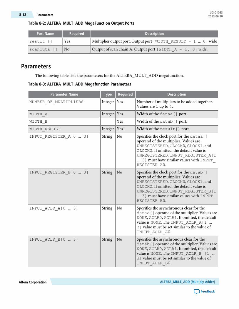
Table 8-2: ALTERA_MULT_ADD MegaFunction Output Ports
DescriptionRequiredPort Name
Multiplier output port. Output port[WIDTH_RESULT - 1 … 0]wideYesresult []
Output of scan chain A. Output port [WIDTH_A - 1..0] wide.Noscanouta []
ParametersThe following table lists the parameters for the ALTERA_MULT_ADD megafunction.
Table 8-3: ALTERA_MULT_ADD Megafunction Parameters
DescriptionRequiredTypeParameter Name
Number of multipliers to be added together.Values are 1 up to 4.
YesIntegerNUMBER_OF_MULTIPLIERS
Width of the dataa[] port.YesIntegerWIDTH_A
Width of the datab[] port.YesWIDTH_B
Width of the result[] port.YesIntegerWIDTH_RESULT
Specifies the clock port for the dataa[]operand of the multiplier. Values areUNREGISTERED, CLOCK0, CLOCK1, andCLOCK2. If omitted, the default value isUNREGISTERED. INPUT_REGISTER_A[1… 3]must have similar values with INPUT_REGISTER_A0.
NoStringINPUT_REGISTER_A[0 … 3]
Specifies the clock port for the datab[]operand of the multiplier. Values areUNREGISTERED, CLOCK0, CLOCK1, andCLOCK2. If omitted, the default value isUNREGISTERED. INPUT_REGISTER_B[1… 3]must have similar values with INPUT_REGISTER_B0.
NoStringINPUT_REGISTER_B[0 … 3]
Specifies the asynchronous clear for thedataa[] operand of themultiplier. Values areNONE, ACLR0, ACLR1. If omitted, the defaultvalue is NONE. The INPUT_ACLR_A[1 …3] value must be set similar to the value ofINPUT_ACLR_A0.
NoStringINPUT_ACLR_A[0 … 3]
Specifies the asynchronous clear for thedatab[] operand of themultiplier. Values areNONE, ACLR0, ACLR1. If omitted, the defaultvalue is NONE. The INPUT_ACLR_B [1 …3] value must be set similar to the value ofINPUT_ACLR_B0.
NoStringINPUT_ACLR_B[0 … 3]
ALTERA_MULT_ADD (Multiply-Adder)Altera Corporation
Feedback
UG-01063Parameters8-12 2013.06.10
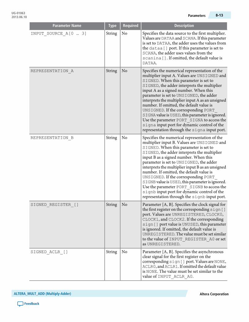
DescriptionRequiredTypeParameter Name
Specifies the data source to the first multiplier.Values areDATAA andSCANA. If this parameteris set to DATAA, the adder uses the values fromthe dataa[] port. If this parameter is set toSCANA, the adder uses values from thescanina[]. If omitted, the default value isDATAA.
NoStringINPUT_SOURCE_A[0 … 3]
Specifies the numerical representation of themultiplier input A. Values are UNSIGNED andSIGNED. When this parameter is set toSIGNED, the adder interprets the multiplierinput A as a signed number. When thisparameter is set to UNSIGNED, the adderinterprets the multiplier input A as an unsignednumber. If omitted, the default value isUNSIGNED. If the corresponding PORT_SIGNA value isUSED, this parameter is ignored.Use the parameter PORT_SIGNA to access thesigna input port for dynamic control of therepresentation through the signa input port.
NoStringREPRESENTATION_A
Specifies the numerical representation of themultiplier input B. Values are UNSIGNED andSIGNED. When this parameter is set toSIGNED, the adder interprets the multiplierinput B as a signed number. When thisparameter is set to UNSIGNED, the adderinterprets the multiplier input B as an unsignednumber. If omitted, the default value isUNSIGNED. If the corresponding PORT_SIGNB value isUSED, this parameter is ignored.Use the parameter PORT_SIGNB to access thesignb input port for dynamic control of therepresentation through the signb input port.
NoStringREPRESENTATION_B
Parameter [A, B]. Specifies the clock signal forthe first register on the correspondingsign[]port. Values are UNREGISTERED, CLOCK0,CLOCK1, and CLOCK2. If the correspondingsign[] port value is UNUSED, this parameteris ignored. If omitted, the default value isUNREGISTERED. The valuemust be set similarto the value of INPUT_REGISTER_A0 or setas UNREGISTERED.
NoStringSIGNED_REGISTER_[]
Parameter [A, B]. Specifies the asynchronousclear signal for the first register on thecorrespondingsign[] port. Values areNONE,ACLR0, andACLR1. If omitted the default valueis NONE. The value must be set similar to thevalue of INPUT_ACLR_A0.
NoStringSIGNED_ACLR_[]
Altera CorporationALTERA_MULT_ADD (Multiply-Adder)
Feedback
8-13ParametersUG-010632013.06.10

DescriptionRequiredTypeParameter Name
Parameter [0...3]. Specifies the clock source ofthe register that follows the correspondingmultiplier. Values are UNREGISTERED,CLOCK0, CLOCK1 and CLOCK2. If omitted,the default value is UNREGISTERED.
NoStringMULTIPLIER_REGISTER[]
Parameter [0...3]. Specifies the asynchronousclear signal of the register that follows thecorresponding multiplier. Values are NONE,ACLR0, andACLR1. If omitted the default valueis NONE.
NoStringMULTIPLIER_ACLR[]
Specifies whether the second multiplier adds orsubtracts its value from the sum.Values areADDand SUB. If the addnsub1 port is used, thisparameter is ignored. If omitted, the defaultvalue is ADD.
NoStringMULTIPLIER1_DIRECTION
Specifies whether the fourth multiplier adds orsubtracts their results from the total. Values areADD and SUB. If the addnsub3 port is used,this parameter is ignored. If omitted, the defaultvalue is ADD.
NoStringMULTIPLIER3_DIRECTION
Specifies the accumulator mode of the finaladder stage. Values areYES andNO. If omitted,the default value is NO.
NoStringACCUMULATOR
Specifies whether the accumulator adds orsubtracts its value from the previous sum.Values areADD andSUB. If omitted, the defaultvalue is ADD.
NoStringACCUM_DIRECTION
Specifies the clock signal for the output register.Values are UNREGISTERED, CLOCK0,CLOCK1 and CLOCK2. If omitted, the defaultvalue is UNREGISTERED.
NoStringOUTPUT_REGISTER
Specifies the asynchronous clear signal for thesecond adder register. Values areNONE,ACLR0,and ACLR1. If omitted, the default value isNONE.
NoStringOUTPUT_ACLR
Parameter [A, B]. Specifies the correspondingsign[a,b] input port usage. Values arePORT_USED and PORT_UNUSED. If omitted,the default value is PORT_UNUSED.
NoStringPORT_SIGN[]
Parameter [1, 3]. Specifies the clock signal forthe register on the correspondingaddnsub[]input. Values are UNREGISTERED, CLOCK0,CLOCK1and CLOCK2. If the correspondingaddnsub[] port is UNUSED, this parameteris ignored. If omitted, the default value isUNREGISTERED.
NoStringADDNSUB_MULTIPLIER_REGISTER[]
ALTERA_MULT_ADD (Multiply-Adder)Altera Corporation
Feedback
UG-01063Parameters8-14 2013.06.10
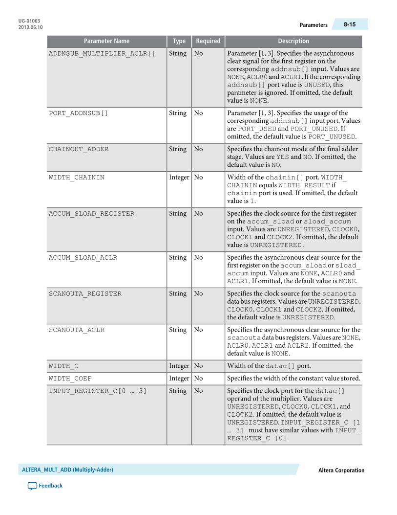
DescriptionRequiredTypeParameter Name
Parameter [1, 3]. Specifies the asynchronousclear signal for the first register on thecorresponding addnsub[] input. Values areNONE,ACLR0 andACLR1. If the correspondingaddnsub[] port value is UNUSED, thisparameter is ignored. If omitted, the defaultvalue is NONE.
NoStringADDNSUB_MULTIPLIER_ACLR[]
Parameter [1, 3]. Specifies the usage of thecorrespondingaddnsub[] input port. Valuesare PORT_USED and PORT_UNUSED. Ifomitted, the default value is PORT_UNUSED.
NoStringPORT_ADDNSUB[]
Specifies the chainout mode of the final adderstage. Values are YES and NO. If omitted, thedefault value is NO.
NoStringCHAINOUT_ADDER
Width of the chainin[] port. WIDTH_CHAININ equals WIDTH_RESULT ifchainin port is used. If omitted, the defaultvalue is 1.
NoIntegerWIDTH_CHAININ
Specifies the clock source for the first registeron the accum_sload or sload_accuminput. Values are UNREGISTERED, CLOCK0,CLOCK1 and CLOCK2. If omitted, the defaultvalue is UNREGISTERED .
NoStringACCUM_SLOAD_REGISTER
Specifies the asynchronous clear source for thefirst register on theaccum_sload orsload_accum input. Values are NONE, ACLR0 andACLR1. If omitted, the default value is NONE.
NoStringACCUM_SLOAD_ACLR
Specifies the clock source for the scanoutadata bus registers. Values areUNREGISTERED,CLOCK0, CLOCK1 and CLOCK2. If omitted,the default value is UNREGISTERED.
NoStringSCANOUTA_REGISTER
Specifies the asynchronous clear source for thescanoutadata bus registers. Values areNONE,ACLR0, ACLR1 and ACLR2. If omitted, thedefault value is NONE.
NoStringSCANOUTA_ACLR
Width of the datac[] port.NoIntegerWIDTH_C
Specifies the width of the constant value stored.NoIntegerWIDTH_COEF
Specifies the clock port for the datac[]operand of the multiplier. Values areUNREGISTERED, CLOCK0, CLOCK1, andCLOCK2. If omitted, the default value isUNREGISTERED.INPUT_REGISTER_C [1… 3] must have similar values with INPUT_REGISTER_C [0].
NoStringINPUT_REGISTER_C[0 … 3]
Altera CorporationALTERA_MULT_ADD (Multiply-Adder)
Feedback
8-15ParametersUG-010632013.06.10
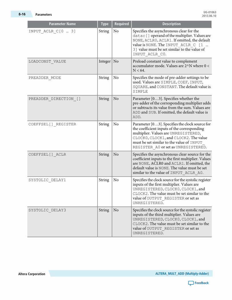
DescriptionRequiredTypeParameter Name
Specifies the asynchronous clear for thedatac[] operand of themultiplier. Values areNONE, ACLR0, ACLR1. If omitted, the defaultvalue is NONE. The INPUT_ACLR_C [1 …3] value must be set similar to the value ofINPUT_ACLR_C0.
NoStringINPUT_ACLR_C[0 … 3]
Preload constant value to complementaccumulator mode. Values are 2^N where 0 <N < 64.
NoIntegerLOADCONST_VALUE
Specifies the mode of pre-adder settings to beused. Values are SIMPLE, COEF, INPUT,SQUARE, and CONSTANT. The default value isSIMPLE
NoStringPREADDER_MODE
Parameter [0…3]. Specifies whether thepre-adder of the corresponding multiplier addsor subtracts its value from the sum. Values areADD and SUB. If omitted, the default value isADD.
NoStringPREADDER_DIRECTION_[]
Parameter [0…3]. Specifies the clock source forthe coefficient inputs of the correspondingmultiplier. Values are UNREGISTERED,CLOCK0, CLOCK1, and CLOCK2. The valuemust be set similar to the value of INPUT_REGISTER_A0 or set as UNREGISTERED.
NoStringCOEFFSEL[]_REGISTER
Specifies the asynchronous clear source for thecoefficient inputs to the first multiplier. Valuesare NONE, ACLR0 and ACLR1. If omitted, thedefault value is NONE. The value must be setsimilar to the value of INPUT_ACLR_A0.
NoStringCOEFFSEL[]_ACLR
Specifies the clock source for the systolic registerinputs of the first multiplier. Values areUNREGISTERED, CLOCK0, CLOCK1, andCLOCK2. The value must be set similar to thevalue of OUTPUT_REGISTER or set asUNREGISTERED.
NoStringSYSTOLIC_DELAY1
Specifies the clock source for the systolic registerinputs of the third multiplier. Values areUNREGISTERED, CLOCK0, CLOCK1, andCLOCK2. The value must be set similar to thevalue of OUTPUT_REGISTER or set asUNREGISTERED.
NoStringSYSTOLIC_DELAY3
ALTERA_MULT_ADD (Multiply-Adder)Altera Corporation
Feedback
UG-01063Parameters8-16 2013.06.10
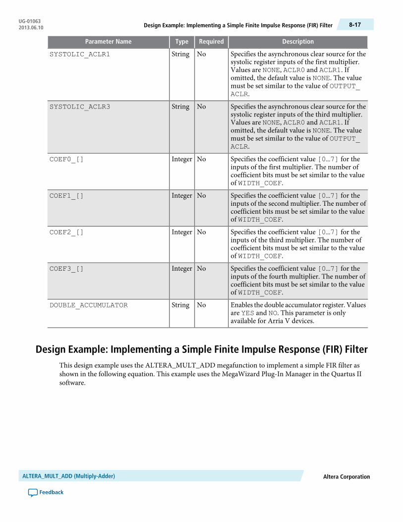
DescriptionRequiredTypeParameter Name
Specifies the asynchronous clear source for thesystolic register inputs of the first multiplier.Values are NONE, ACLR0 and ACLR1. Ifomitted, the default value is NONE. The valuemust be set similar to the value of OUTPUT_ACLR.
NoStringSYSTOLIC_ACLR1
Specifies the asynchronous clear source for thesystolic register inputs of the third multiplier.Values are NONE, ACLR0 and ACLR1. Ifomitted, the default value is NONE. The valuemust be set similar to the value of OUTPUT_ACLR.
NoStringSYSTOLIC_ACLR3
Specifies the coefficient value [0…7] for theinputs of the first multiplier. The number ofcoefficient bits must be set similar to the valueof WIDTH_COEF.
NoIntegerCOEF0_[]
Specifies the coefficient value [0…7] for theinputs of the second multiplier. The number ofcoefficient bits must be set similar to the valueof WIDTH_COEF.
NoIntegerCOEF1_[]
Specifies the coefficient value [0…7] for theinputs of the third multiplier. The number ofcoefficient bits must be set similar to the valueof WIDTH_COEF.
NoIntegerCOEF2_[]
Specifies the coefficient value [0…7] for theinputs of the fourth multiplier. The number ofcoefficient bits must be set similar to the valueof WIDTH_COEF.
NoIntegerCOEF3_[]
Enables the double accumulator register. Valuesare YES and NO. This parameter is onlyavailable for Arria V devices.
NoStringDOUBLE_ACCUMULATOR
Design Example: Implementing a Simple Finite Impulse Response (FIR) FilterThis design example uses the ALTERA_MULT_ADD megafunction to implement a simple FIR filter asshown in the following equation. This example uses the MegaWizard Plug-In Manager in the Quartus IIsoftware.
Altera CorporationALTERA_MULT_ADD (Multiply-Adder)
Feedback
8-17Design Example: Implementing a Simple Finite Impulse Response (FIR) FilterUG-010632013.06.10

n represents the number of taps, A(t) represents the sequence of input samples, and B(i) represents the filtercoefficients.
The number of taps (n) can be any value, but this example is of a simple FIR filter with n = 4, which is calleda 4-tap filter. To implement this filter, the coefficients of data B is loaded into the B registers in parallel anda shiftin register moves data A(0) to A(1) to A(2), and so on. With a 4-tap filter, at a given time (t), thesum of four products is computed. This function is implemented using the shift register chain option in theALTMULT_ADD megafunction.
With reference to the equation, input B represents the coefficients and data A represents the data that isshifted into. The A input (data) is shifted in with the main clock, named clock0. The B input (coefficients)is loaded at the rising edge of clock1 with the enable signal held high.
The following design files can be found in altmult_add_DesignExample.zip:
fir_fourtap.qar (archived Quartus II design files)
altmult_add_ex_msim (ModelSim-Altera files)
Understanding the Simulation ResultsThe following settings are observed in this example:
• The widths of the data inputs are all set to 16 bits• The width of the output port, result[], is set to 34 bits• The input registers are all operating on the same clock
The following figure shows the expected simulation results in the ModelSim-Altera software.
Figure 8-13: ALTERA_MULT_ADD Simulation Results
ALTERA_MULT_ADD (Multiply-Adder)Altera Corporation
Feedback
UG-01063Understanding the Simulation Results8-18 2013.06.10
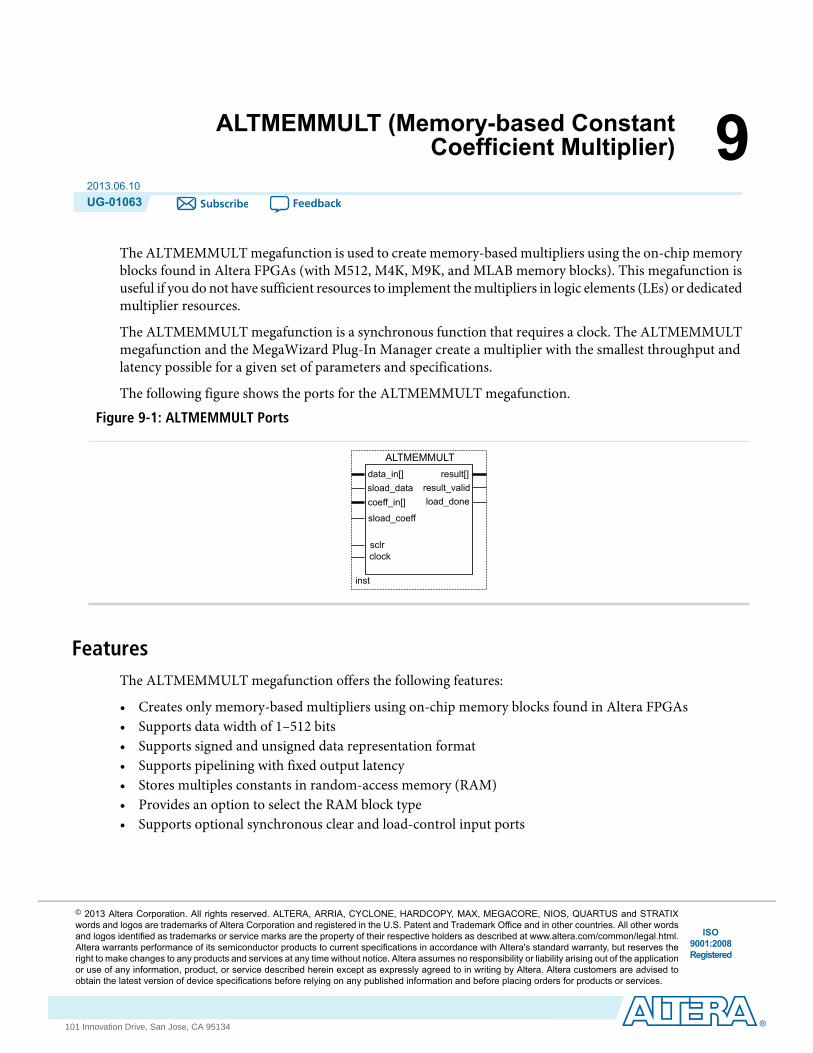
9ALTMEMMULT (Memory-based ConstantCoefficient Multiplier)
2013.06.10UG-01063 Subscribe Feedback
The ALTMEMMULT megafunction is used to create memory-based multipliers using the on-chip memoryblocks found in Altera FPGAs (with M512, M4K, M9K, and MLAB memory blocks). This megafunction isuseful if you do not have sufficient resources to implement themultipliers in logic elements (LEs) or dedicatedmultiplier resources.
The ALTMEMMULT megafunction is a synchronous function that requires a clock. The ALTMEMMULTmegafunction and the MegaWizard Plug-In Manager create a multiplier with the smallest throughput andlatency possible for a given set of parameters and specifications.
The following figure shows the ports for the ALTMEMMULT megafunction.
Figure 9-1: ALTMEMMULT Ports
data_in[]
inst
ALTMEMMULT
coeff_in[]sload_data
result[]result_valid
sload_coeff
sclrclock
load_done
FeaturesThe ALTMEMMULT megafunction offers the following features:
• Creates only memory-based multipliers using on-chip memory blocks found in Altera FPGAs• Supports data width of 1–512 bits• Supports signed and unsigned data representation format• Supports pipelining with fixed output latency• Stores multiples constants in random-access memory (RAM)• Provides an option to select the RAM block type• Supports optional synchronous clear and load-control input ports
ISO9001:2008Registered
© 2013 Altera Corporation. All rights reserved. ALTERA, ARRIA, CYCLONE, HARDCOPY, MAX, MEGACORE, NIOS, QUARTUS and STRATIXwords and logos are trademarks of Altera Corporation and registered in the U.S. Patent and Trademark Office and in other countries. All other wordsand logos identified as trademarks or service marks are the property of their respective holders as described at www.altera.com/common/legal.html.Altera warrants performance of its semiconductor products to current specifications in accordance with Altera's standard warranty, but reserves theright to make changes to any products and services at any time without notice. Altera assumes no responsibility or liability arising out of the applicationor use of any information, product, or service described herein except as expressly agreed to in writing by Altera. Altera customers are advised toobtain the latest version of device specifications before relying on any published information and before placing orders for products or services.
www.altera.com
101 Innovation Drive, San Jose, CA 95134
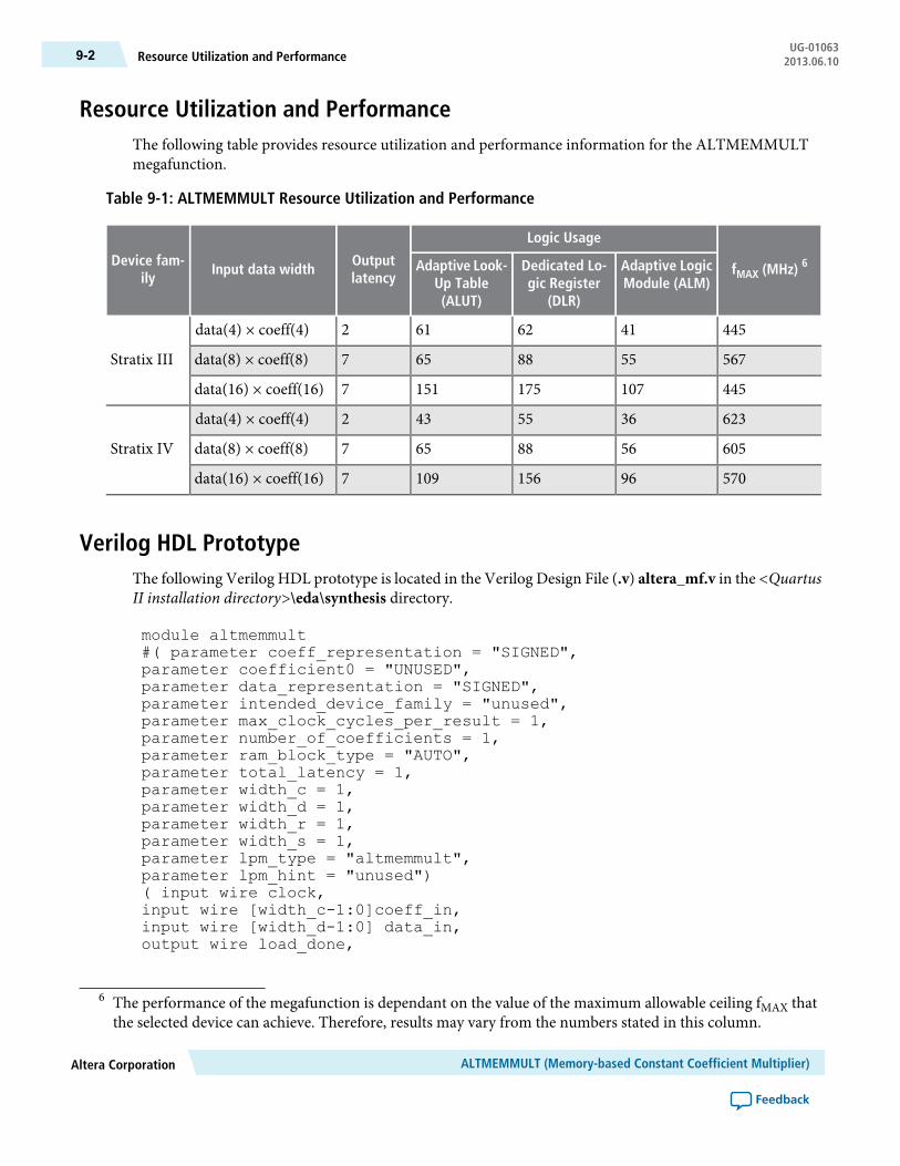
Resource Utilization and PerformanceThe following table provides resource utilization and performance information for the ALTMEMMULTmegafunction.
Table 9-1: ALTMEMMULT Resource Utilization and Performance
fMAX (MHz) 6
Logic Usage
Outputlatency
Input data widthDevice fam-
ilyAdaptive LogicModule (ALM)
Dedicated Lo-gic Register
(DLR)
Adaptive Look-Up Table(ALUT)
4454162612data(4) × coeff(4)
Stratix III 5675588657data(8) × coeff(8)
4451071751517data(16) × coeff(16)
6233655432data(4) × coeff(4)
Stratix IV 6055688657data(8) × coeff(8)
570961561097data(16) × coeff(16)
Verilog HDL PrototypeThe following Verilog HDL prototype is located in the Verilog Design File (.v) altera_mf.v in the <QuartusII installation directory>\eda\synthesis directory.
module altmemmult#( parameter coeff_representation = "SIGNED",parameter coefficient0 = "UNUSED",parameter data_representation = "SIGNED",parameter intended_device_family = "unused",parameter max_clock_cycles_per_result = 1,parameter number_of_coefficients = 1,parameter ram_block_type = "AUTO",parameter total_latency = 1,parameter width_c = 1,parameter width_d = 1,parameter width_r = 1,parameter width_s = 1,parameter lpm_type = "altmemmult",parameter lpm_hint = "unused")( input wire clock,input wire [width_c-1:0]coeff_in,input wire [width_d-1:0] data_in,output wire load_done,
6 The performance of the megafunction is dependant on the value of the maximum allowable ceiling fMAX thatthe selected device can achieve. Therefore, results may vary from the numbers stated in this column.
ALTMEMMULT (Memory-based Constant Coefficient Multiplier)Altera Corporation
Feedback
UG-01063Resource Utilization and Performance9-2 2013.06.10
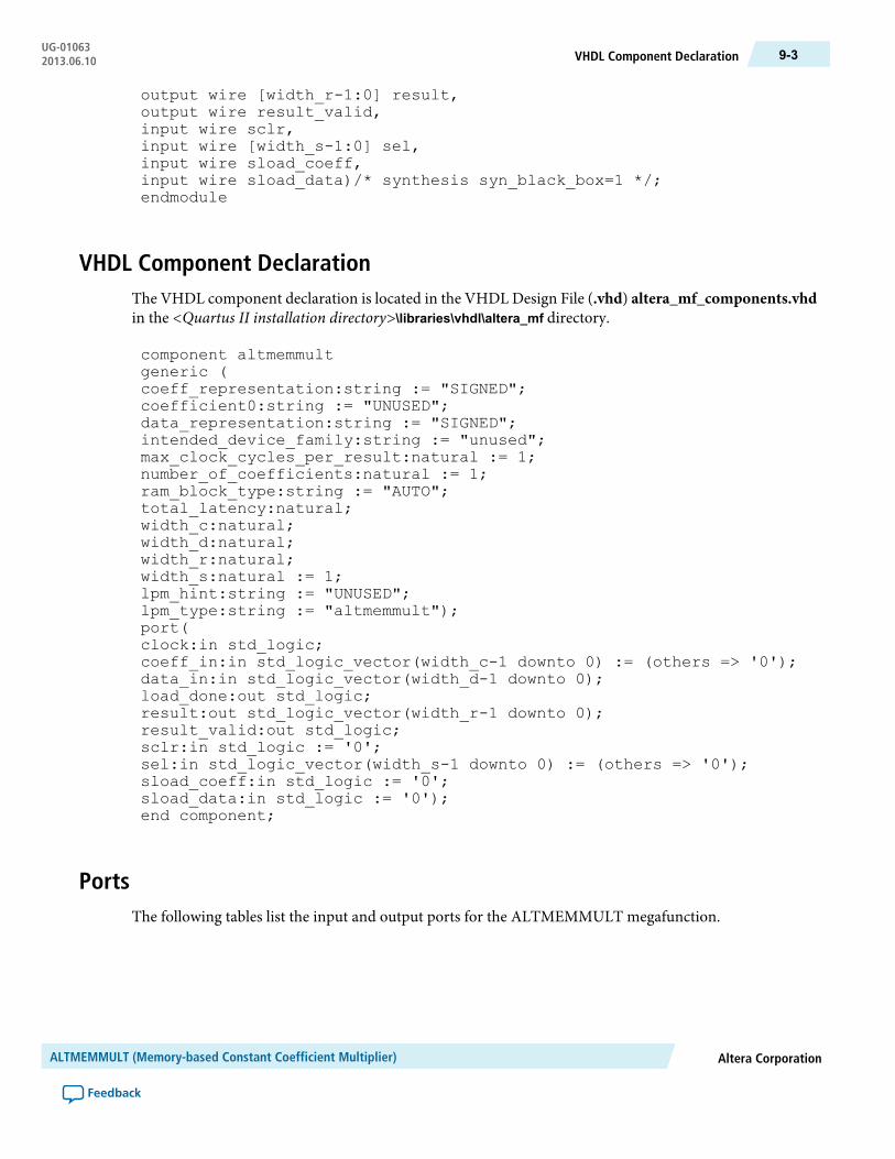
output wire [width_r-1:0] result,output wire result_valid,input wire sclr,input wire [width_s-1:0] sel,input wire sload_coeff,input wire sload_data)/* synthesis syn_black_box=1 */;endmodule
VHDL Component DeclarationThe VHDL component declaration is located in the VHDL Design File (.vhd) altera_mf_components.vhdin the <Quartus II installation directory>\libraries\vhdl\altera_mf directory.
component altmemmultgeneric (coeff_representation:string := "SIGNED";coefficient0:string := "UNUSED";data_representation:string := "SIGNED";intended_device_family:string := "unused";max_clock_cycles_per_result:natural := 1;number_of_coefficients:natural := 1;ram_block_type:string := "AUTO";total_latency:natural;width_c:natural;width_d:natural;width_r:natural;width_s:natural := 1;lpm_hint:string := "UNUSED";lpm_type:string := "altmemmult");port(clock:in std_logic;coeff_in:in std_logic_vector(width_c-1 downto 0) := (others => '0');data_in:in std_logic_vector(width_d-1 downto 0);load_done:out std_logic;result:out std_logic_vector(width_r-1 downto 0);result_valid:out std_logic;sclr:in std_logic := '0';sel:in std_logic_vector(width_s-1 downto 0) := (others => '0');sload_coeff:in std_logic := '0';sload_data:in std_logic := '0');end component;
PortsThe following tables list the input and output ports for the ALTMEMMULT megafunction.
Altera CorporationALTMEMMULT (Memory-based Constant Coefficient Multiplier)
Feedback
9-3VHDL Component DeclarationUG-010632013.06.10

Table 9-2: ALTMEMMULT Megafunction Input Ports
DescriptionRequiredPort Name
Clock input to the multiplier.Yesclock
Coefficient input port for the multiplier. The size of the input port dependson the WIDTH_C parameter value.
Nocoeff_in[]
Data input port to the multiplier. The size of the input port depends on theWIDTH_D parameter value.
Yesdata_in[]
Synchronous clear input. If unused, the default value is active high.Nosclr
Fixed coefficient selection. The size of the input port depends on theWIDTH_S parameter value.
Nosel[]
Synchronous load coefficient input port. Replaces the current selectedcoefficient value with the value specified in the coeff_in input.
Nosload_coeff
Synchronous load data input port. Signal that specifies new multiplicationoperation and cancels any existing multiplication operation. If the MAX_CLOCK_CYCLES_PER_RESULT parameter has a value of 1, the sload_data input port is ignored.
Nosload_data
Table 9-3: ALTMEMMULT Megafunction Output Ports
DescriptionRequiredPort Name
Multiplier output port. The size of the input port depends on the WIDTH_Rparameter value.
Yesresult[]
Indicates when the output is the valid result of a complete multiplication. Ifthe MAX_CLOCK_CYCLES_PER_RESULT parameter has a value of 1, theresult_valid output port is not used.
Yesresult_valid
Indicates when the new coefficient has finished loading. The load_donesignal asserts when a new coefficient has finished loading. Unless the load_done signal is high, no other coefficient value can be loaded into thememory.
Noload_done
ParametersThe following table lists the parameters for the ALTMEMMULT megafunction.
Table 9-4: ALTMEMMULT Megafunction Parameters
DescriptionRequiredTypeParameter Name
Specifies the width of the data_in[]port.
YesIntegerWIDTH_D
Specifies the width of the coeff_in[]port.
YesIntegerWIDTH_C
ALTMEMMULT (Memory-based Constant Coefficient Multiplier)Altera Corporation
Feedback
UG-01063Parameters9-4 2013.06.10
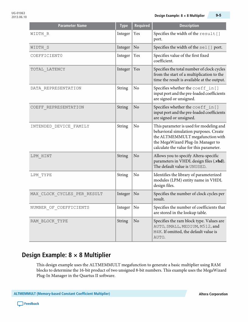
DescriptionRequiredTypeParameter Name
Specifies the width of the result[]port.
YesIntegerWIDTH_R
Specifies the width of the sel[] port.NoIntegerWIDTH_S
Specifies value of the first fixedcoefficient.
YesIntegerCOEFFICIENT0
Specifies the total number of clock cyclesfrom the start of a multiplication to thetime the result is available at the output.
YesIntegerTOTAL_LATENCY
Specifies whether the coeff_in[]input port and the pre-loaded coefficientsare signed or unsigned.
NoStringDATA_REPRESENTATION
Specifies whether the coeff_in[]input port and the pre-loaded coefficientsare signed or unsigned.
NoStringCOEFF_REPRESENTATION
This parameter is used for modeling andbehavioral simulation purposes. CreatetheALTMEMMULTmegafunctionwiththe MegaWizard Plug-In Manager tocalculate the value for this parameter.
NoStringINTENDED_DEVICE_FAMILY
Allows you to specify Altera-specificparameters in VHDL design files (.vhd).The default value is UNUSED.
NoStringLPM_HINT
Identifies the library of parameterizedmodules (LPM) entity name in VHDLdesign files.
NoStringLPM_TYPE
Specifies the number of clock cycles perresult.
NoIntegerMAX_CLOCK_CYCLES_PER_RESULT
Specifies the number of coefficients thatare stored in the lookup table.
NoIntegerNUMBER_OF_COEFFICIENTS
Specifies the ram block type. Values areAUTO, SMALL, MEDIUM, M512, andM4K. If omitted, the default value isAUTO.
NoStringRAM_BLOCK_TYPE
Design Example: 8 × 8 MultiplierThis design example uses the ALTMEMMULT megafunction to generate a basic multiplier using RAMblocks to determine the 16-bit product of two unsigned 8-bit numbers. This example uses the MegaWizardPlug-In Manager in the Quartus II software.
Altera CorporationALTMEMMULT (Memory-based Constant Coefficient Multiplier)
Feedback
9-5Design Example: 8 × 8 MultiplierUG-010632013.06.10
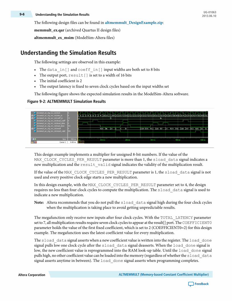
The following design files can be found in altmemmult_DesignExample.zip:
memmult_ex.qar (archived Quartus II design files)
altmemmult_ex_msim (ModelSim-Altera files)
Understanding the Simulation ResultsThe following settings are observed in this example:
• The data_in[] and coeff_in[] input widths are both set to 8 bits• The output port, result[] is set to a width of 16 bits• The initial coefficient is 2• The output latency is fixed to seven clock cycles based on the input widths set
The following figure shows the expected simulation results in the ModelSim-Altera software.
Figure 9-2: ALTMEMMULT Simulation Results
This design example implements a multiplier for unsigned 8-bit numbers. If the value of theMAX_CLOCK_CYCLES_PER_RESULT parameter is more than 1, the sload_data signal indicates anew multiplication and the result_valid signal indicates the validity of the multiplication result.
If the value of the MAX_CLOCK_CYCLES_PER_RESULT parameter is 1, the sload_data signal is notused and every positive clock edge starts a new multiplication.
In this design example, with the MAX_CLOCK_CYCLES_PER_RESULT parameter set to 4, the designrequires no less than four clock cycles to compute the multiplication. The sload_data signal is used toindicate a new multiplication.
Altera recommends that you do not pull the sload_data signal high during the four clock cycleswhen the multiplication is taking place to avoid getting unpredictable results.
Note:
The megafunction only receive new inputs after four clock cycles. With the TOTAL_LATENCY parameterset to 7, allmultiplication results require seven clock cycles to appear at the result[] port. TheCOEFFICIENT0parameter holds the value of the first fixed coefficient, which is set to 2 (COEFFICIENT0=2) for this designexample. The megafunction uses the latest coefficient value for every multiplication.
The sload_data signal asserts when a new coefficient value is written into the register. The load_donesignal pulls low one clock cycle after the sload_data signal deasserts. When the load_done signal islow, the new coefficient value is reprogrammed into the RAM look-up table. Until the load_done signalpulls high, no other coefficient value can be loaded into thememory (regardless of whether thesload_datasignal asserts anytime in between). The load_done signal asserts when programming completes.
ALTMEMMULT (Memory-based Constant Coefficient Multiplier)Altera Corporation
Feedback
UG-01063Understanding the Simulation Results9-6 2013.06.10
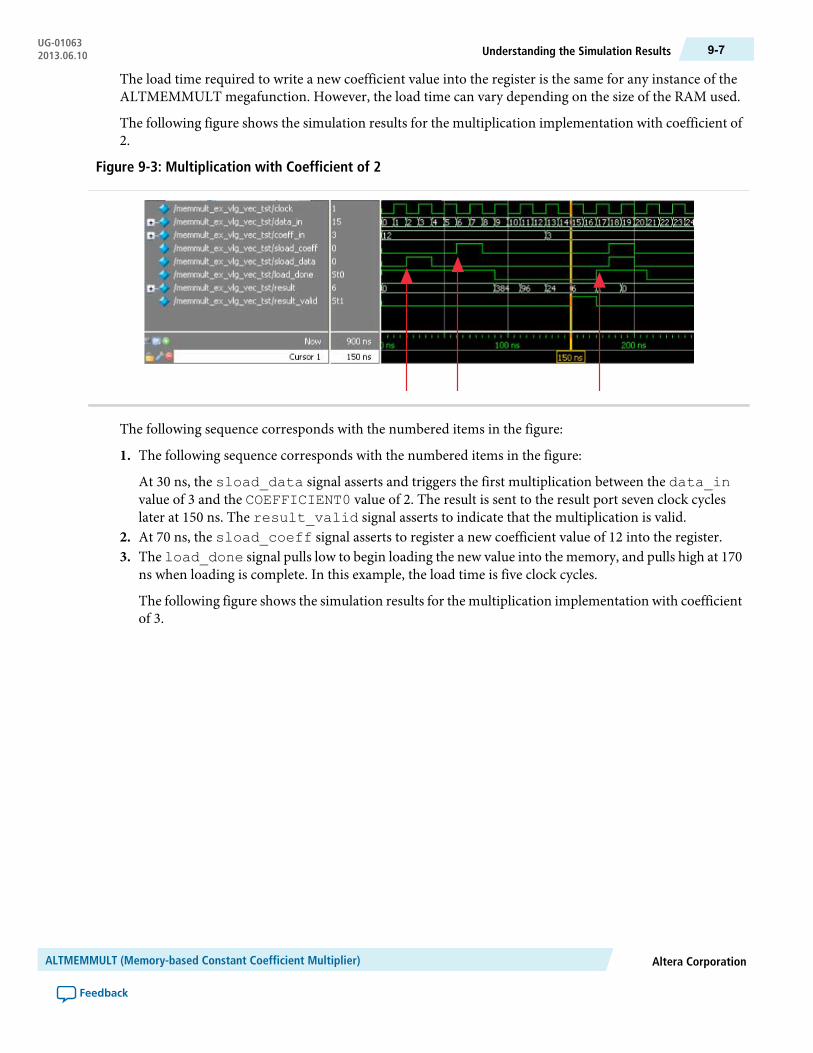
The load time required to write a new coefficient value into the register is the same for any instance of theALTMEMMULT megafunction. However, the load time can vary depending on the size of the RAM used.
The following figure shows the simulation results for the multiplication implementation with coefficient of2.
Figure 9-3: Multiplication with Coefficient of 2
The following sequence corresponds with the numbered items in the figure:
1. The following sequence corresponds with the numbered items in the figure:
At 30 ns, the sload_data signal asserts and triggers the first multiplication between the data_invalue of 3 and the COEFFICIENT0 value of 2. The result is sent to the result port seven clock cycleslater at 150 ns. The result_valid signal asserts to indicate that the multiplication is valid.
2. At 70 ns, the sload_coeff signal asserts to register a new coefficient value of 12 into the register.3. The load_done signal pulls low to begin loading the new value into the memory, and pulls high at 170
ns when loading is complete. In this example, the load time is five clock cycles.
The following figure shows the simulation results for the multiplication implementation with coefficientof 3.
Altera CorporationALTMEMMULT (Memory-based Constant Coefficient Multiplier)
Feedback
9-7Understanding the Simulation ResultsUG-010632013.06.10

Figure 9-4: Multiplication with Coefficient of 3
1. At 190 ns, the sload_coeff signal asserts to register a new coefficient value of 3. The sload_datasignal asserts and triggers a newmultiplication. The latest value of the coefficient loaded into thememoryis 12. Multiplication occurs between the data_in value of 19 and a coefficient of 12. At the same time,at 190 ns, the sload_coeff signal asserts and triggers the programming of coefficient 3. Although themultiplication result of 228 at 310 ns is valid, the result_valid signal does not pull high.
2. At 300 ns, the sload_data signal asserts and triggers a new multiplication. However, at 350 ns (lessthan four clock cycles after 300 ns), the sload_data signal pulls high again and cancels the previousmultiplication process.
3. Multiplication finally occurs between the data_in value of 35 and a coefficient of 3 at 350 ns.The validresult, 105, of the computation is displayed at 470 ns.
Altera recommends that you do not assert both the sload_coeff and sload_data signalsat the same time to prevent the programming and computation processes from occurringsimultaneously.
Note:
ALTMEMMULT (Memory-based Constant Coefficient Multiplier)Altera Corporation
Feedback
UG-01063Understanding the Simulation Results9-8 2013.06.10

10ALTMULT_ACCUM (Multiply-Accumulate)
2013.06.10UG-01063 Subscribe Feedback
The ALTMULT_ACCUM megafunction allows you to implement a multiplier-adder.
• TheALTMULT_ACCUMmegafunction is scheduled for product obsolescence anddiscontinuedsupport for Arria V, Cyclone V, and Stratix V devices, with last ship date the Quartus II software13.0 release.
• Therefore, for Arria V, Cyclone V, and Stratix V devices, Altera recommends using theALTERA_MULT_ADD (Multiply-Adder) on page 8-1 instead.
Note:
The following figure shows the ports for the ALTMULT_ACCUM megafunction.
Figure 10-1: ALTMULT_ACCUM Ports
dataa[]
inst
ALTMULT_ACCUM
sourceascanina[] scanouta[]
signadatab[]scaninb[]sourcebsignb
accum_sloadaccum_sload_upper_data[]addnsubmult_roundmult_saturationclock0ena0clock1ena1clock2ena2clock3ena3
scanoutb[]
result[]
overflow
mult_is_saturated
accum_is_saturated
aclr0
aclr1
aclr2
aclr3
datac[]coefsel[]
ISO9001:2008Registered
© 2013 Altera Corporation. All rights reserved. ALTERA, ARRIA, CYCLONE, HARDCOPY, MAX, MEGACORE, NIOS, QUARTUS and STRATIXwords and logos are trademarks of Altera Corporation and registered in the U.S. Patent and Trademark Office and in other countries. All other wordsand logos identified as trademarks or service marks are the property of their respective holders as described at www.altera.com/common/legal.html.Altera warrants performance of its semiconductor products to current specifications in accordance with Altera's standard warranty, but reserves theright to make changes to any products and services at any time without notice. Altera assumes no responsibility or liability arising out of the applicationor use of any information, product, or service described herein except as expressly agreed to in writing by Altera. Altera customers are advised toobtain the latest version of device specifications before relying on any published information and before placing orders for products or services.
www.altera.com
101 Innovation Drive, San Jose, CA 95134

A multiplier-accumulator accepts a pair of inputs, multiplies the two inputs together, and feeds their resultinto an accumulator to be added to or subtracted from its previous registered result. This function is expressedin the following equation.
Where N is the number of cycles of data that has been entered into the accumulator.
FeaturesThe ALTMULT_ACCUM megafunction offers the following features:
• Generates a multiplier-accumulator• Supports data widths of 1–256 bits• Supports signed and unsigned data representation format• Supports pipelining with configurable output latency• Provides a choice of implementation in dedicated DSP block circuitry or logic elements (LEs)• Provides an option to dynamically switch between add and subtract operations in the accumulator• Provides an option to dynamically switch between signed and unsigned data support• Provides an option to set up data shift register chains• Supports hardware saturation and rounding (for Stratix III and Stratix IV devices only)• Supports optional asynchronous clear and clock enable input ports
Refer to the following megafunctions in this user guide for other multiplier implementations:
• Multiplier-Adder Megafunction (ALTMULT_ADD)• Memory-basedConstantCoefficientMultiplier (ALTMEMMULT(Memory-basedConstantCoefficient
Multiplier))• Multiplier Megafunction (LPM_MULT (Multiplier))
Resource Utilization and PerformanceThe following table provides resource utilization and performance information for theALTMULT_ACCUMmegafunction.
ALTMULT_ACCUM (Multiply-Accumulate)Altera Corporation
Feedback
UG-01063Features10-2 2013.06.10
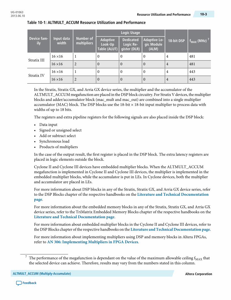
Table 10-1: ALTMULT_ACCUM Resource Utilization and Performance
fMAX (MHz) 718-bit DSP
Logic Usage
Number ofmultipliers
Input datawidth
Device fam-ily
Adaptive Lo-gic Module
(ALM)
DedicatedLogic Re-
gister (DLR)
AdaptiveLook-Up
Table (ALUT)
4814000116 ×16Stratix III
4814000216 ×16
4434000116 ×16Stratix IV
4434000216 ×16
In the Stratix, Stratix GX, and Arria GX device series, the multiplier and the accumulator of theALTMULT_ACCUMmegafunction are placed in theDSPblock circuitry. For StratixVdevices, themultiplierblocks and adder/accumulator block (mac_mult and mac_out) are combined into a single multiplieraccumulator (MAC) block. The DSP blocks use the 18-bit × 18-bit input multiplier to process data withwidths of up to 18 bits.
The registers and extra pipeline registers for the following signals are also placed inside the DSP block:
• Data input• Signed or unsigned select• Add or subtract select• Synchronous load• Products of multipliers
In the case of the output result, the first register is placed in the DSP block. The extra latency registers areplaced in logic elements outside the block.
Cyclone II and Cyclone III devices have embedded multiplier blocks. When the ALTMULT_ACCUMmegafunction is implemented in Cyclone II and Cyclone III devices, the multiplier is implemented in theembedded multiplier blocks, while the accumulator is put in LEs. In Cyclone devices, both the multiplierand accumulator are placed in LEs.
For more information about DSP blocks in any of the Stratix, Stratix GX, and Arria GX device series, referto the DSP Blocks chapter of the respective handbooks on the Literature and Technical Documentationpage.
For more information about the embedded memory blocks in any of the Stratix, Stratix GX, and Arria GXdevice series, refer to the TriMatrix Embedded Memory Blocks chapter of the respective handbooks on theLiterature and Technical Documentation page.
For more information about embedded multiplier blocks in the Cyclone II and Cyclone III devices, refer totheDSPBlocks chapter of the respective handbooks on the Literature andTechnicalDocumentation page.
For more information about implementing multipliers using DSP and memory blocks in Altera FPGAs,refer to AN 306: Implementing Multipliers in FPGA Devices.
7 The performance of the megafunction is dependant on the value of the maximum allowable ceiling fMAX thatthe selected device can achieve. Therefore, results may vary from the numbers stated in this column.
Altera CorporationALTMULT_ACCUM (Multiply-Accumulate)
Feedback
10-3Resource Utilization and PerformanceUG-010632013.06.10

Verilog HDL PrototypeTo view the Verilog HDL prototype for the megafunction, refer to the Verilog Design File (.v) altera_mf.vin the <Quartus II installation directory>\eda\synthesis directory.
VHDL Component DeclarationTo view the VHDL component declaration for the megafunction, refer to the VHDL Design File (.vhd)altera_mf_components.vhd in the <Quartus II installation directory>\libraries\vhdl\altera_mf directory.
VHDL LIBRARY_USE DeclarationThe VHDL LIBRARY-USE declaration is not required if you use the VHDL Component Declaration.
LIBRARY altera_mf;USE altera_mf.altera_mf_components.all;
PortsThe following tables list the input and output ports for the ALTMULT_ACCUM megafunction.
Table 10-2: ALTMULT_ACCUM Megafunction Input Ports
DescriptionRequiredPort Name
Causes the value on the accumulator feedback path to go to zero(0) or to accum_sload_upper_data when concatenatedwith 0. If the accumulator is adding and theaccum_sload portis high, then themultiplier output is loaded into the accumulator.If the accumulator is subtracting, then the opposite (negativevalue) of the multiplier output is loaded into the accumulator.
Noaccum_sload
The first asynchronous clear input. The aclr0 port is activehigh.
Noaclr0
The second asynchronous clear input. The aclr1 port is activehigh.
Noaclr1
The third asynchronous clear input. The aclr2 port is activehigh.
Noaclr2
The fourth asynchronous clear input. The aclr3 port is activehigh.
Noaclr3
Controls the functionality of the adder. If the addnsub port ishigh, the adder performs an add function; if the addnsub portis low, the adder performs a subtract function.
Noaddnsub
ALTMULT_ACCUM (Multiply-Accumulate)Altera Corporation
Feedback
UG-01063Verilog HDL Prototype10-4 2013.06.10
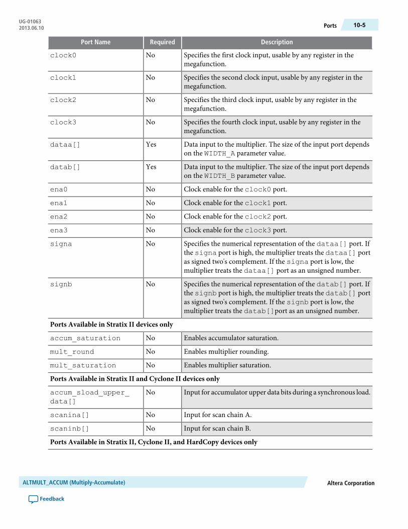
DescriptionRequiredPort Name
Specifies the first clock input, usable by any register in themegafunction.
Noclock0
Specifies the second clock input, usable by any register in themegafunction.
Noclock1
Specifies the third clock input, usable by any register in themegafunction.
Noclock2
Specifies the fourth clock input, usable by any register in themegafunction.
Noclock3
Data input to the multiplier. The size of the input port dependson the WIDTH_A parameter value.
Yesdataa[]
Data input to the multiplier. The size of the input port dependson the WIDTH_B parameter value.
Yesdatab[]
Clock enable for the clock0 port.Noena0
Clock enable for the clock1 port.Noena1
Clock enable for the clock2 port.Noena2
Clock enable for the clock3 port.Noena3
Specifies the numerical representation of the dataa[] port. Ifthe signa port is high, the multiplier treats the dataa[] portas signed two's complement. If the signa port is low, themultiplier treats the dataa[] port as an unsigned number.
Nosigna
Specifies the numerical representation of the datab[] port. Ifthe signb port is high, the multiplier treats the datab[] portas signed two's complement. If the signb port is low, themultiplier treats the datab[]port as an unsigned number.
Nosignb
Ports Available in Stratix II devices only
Enables accumulator saturation.Noaccum_saturation
Enables multiplier rounding.Nomult_round
Enables multiplier saturation.Nomult_saturation
Ports Available in Stratix II and Cyclone II devices only
Input for accumulator upper data bits during a synchronous load.Noaccum_sload_upper_data[]
Input for scan chain A.Noscanina[]
Input for scan chain B.Noscaninb[]
Ports Available in Stratix II, Cyclone II, and HardCopy devices only
Altera CorporationALTMULT_ACCUM (Multiply-Accumulate)
Feedback
10-5PortsUG-010632013.06.10

DescriptionRequiredPort Name
Input source for scan chain A and dynamically controls whetherthe scanina[] and dataa[] ports are fed to the multiplier.
Nosourcea
Input source for scan chain B.Nosourceb
Ports Available in Stratix III and Stratix IV devices only
Enables accumulator rounding.Noaccum_round
Table 10-3: ALTMULT_ACCUM Megafunction Output Ports
DescriptionRequiredPort Name
Overflow port for the accumulator.Nooverflow
Accumulator output port. The size of the output port dependson the WIDTH_RESULT parameter value.
Yesresult[]
Output of the first shift register. The size of the output portdepends on the WIDTH_A parameter value. When instantiatingthe ALTMULT_ACCUM megafunction with the MegaWizardPlug-In Manager, the MegaWizard Plug-In Manager renamesthe scanouta[] port to shiftouta port.
Noscanouta[]
Output of the second shift register. The size of the input portdepends on the WIDTH_B parameter value. When instantiatingthe ALTMULT_ACCUM megafunction with the MegaWizardPlug-In Manager, the MegaWizard Plug-In Manager renamesthe scanoutb[] port to shiftoutb port.
Noscanoutb[]
Ports Available in Stratix II devices only
Signal that indicates when accumulator saturation occurs. Thisport is available when the PORT_ACCUM_IS_SATURATEDparameter is set to USED.
Noaccum_is_saturated
Signal that indicates whenmultiplier saturation occurs. This portis availablewhen thePORT_MULT_IS_SATURATEDparameteris set to USED.
Nomult_is_saturated
ParametersThe following table lists the parameters for the ALTMULT_ACCUM megafunction.
ALTMULT_ACCUM (Multiply-Accumulate)Altera Corporation
Feedback
UG-01063Parameters10-6 2013.06.10

Table 10-4: ALTMULT_ACCUM Megafunction Parameters
DescriptionRequiredTypeParameter Name
Specifies whether theaccumulator performs an add orsubtract function. Values areADD and SUB. When thisparameter is set to ADD, theaccumulator adds the product tothe current accumulator value.When this parameter is set toSUB, the accumulator subtractsthe product from the currentaccumulator value. If omitted thedefault value is ADD. Thisparameter is ignored if theaddnsub port is used.
NoStringACCUM_DIRECTION
Specifies the asynchronous clearsignal for the accum_sloadport. Values areACLR0,ACLR1,ACLR2, and ACLR3. If omittedthe default value is ACLR3. Thisparameter is ignored if theaccum_sload port is unused.
NoStringACCUM_SLOAD_ACLR
Specifies the asynchronous clearsignal for the second register onthe accum_sload port.Values are ACLR0, ACLR1,ACLR2, and ACLR3. If omittedthe default value is ACLR3. Thisparameter is ignored if theaccum_sload port is unused.
NoStringACCUM_SLOAD_PIPELINE_ACLR
Specifies the clock signal for thesecond register on the accum_sload port. Values areUNREGISTERED, CLOCK0,CLOCK1, CLOCK2, andCLOCK3. If omitted, the defaultvalue isCLOCK0. This parameteris ignored if theaccum_sloadport is unused.
NoStringACCUM_SLOAD_PIPELINE_REG
Altera CorporationALTMULT_ACCUM (Multiply-Accumulate)
Feedback
10-7ParametersUG-010632013.06.10

DescriptionRequiredTypeParameter Name
Specifies the clock signal for theaccum_sloadport. Values areUNREGISTERED, CLOCK0,CLOCK1, CLOCK2, andCLOCK3. If omitted, the defaultvalue isCLOCK0. This parameteris ignored if theaccum_sloadport is unused.
NoStringACCUM_SLOAD_REG
Specifies the asynchronous clearfor the addnsub port. ValuesareACLR0,ACLR1,ACLR2, andACLR3. If omitted the defaultvalue is ACLR0. This parameteris ignored if the addnsub portis unused.
NoStringADDNSUB_ACLR
Specifies the asynchronous clearfor the second register on theaddnsub port. Values areACLR0, ACLR1, ACLR2, andACLR3. If omitted the defaultvalue is ACLR0. This parameteris ignored if the addnsub portis unused.
NoStringADDNSUB_PIPELINE_ACLR
Specifies the clock for the secondregister on the addnsub port.Values are UNREGISTERED,CLOCK0, CLOCK1, CLOCK2,and CLOCK3. If omitted, thedefault value is CLOCK0. Thisparameter is ignored if theaddnsub port is unused.
NoStringADDNSUB_PIPELINE_REG
Specifies the clock for theaddnsub port. Values areUNREGISTERED, CLOCK0,CLOCK1, CLOCK2, andCLOCK3. If omitted, the defaultvalue isCLOCK0. This parameteris ignored if the addnsub portis unused.
NoStringADDNSUB_REG
ALTMULT_ACCUM (Multiply-Accumulate)Altera Corporation
Feedback
UG-01063Parameters10-8 2013.06.10
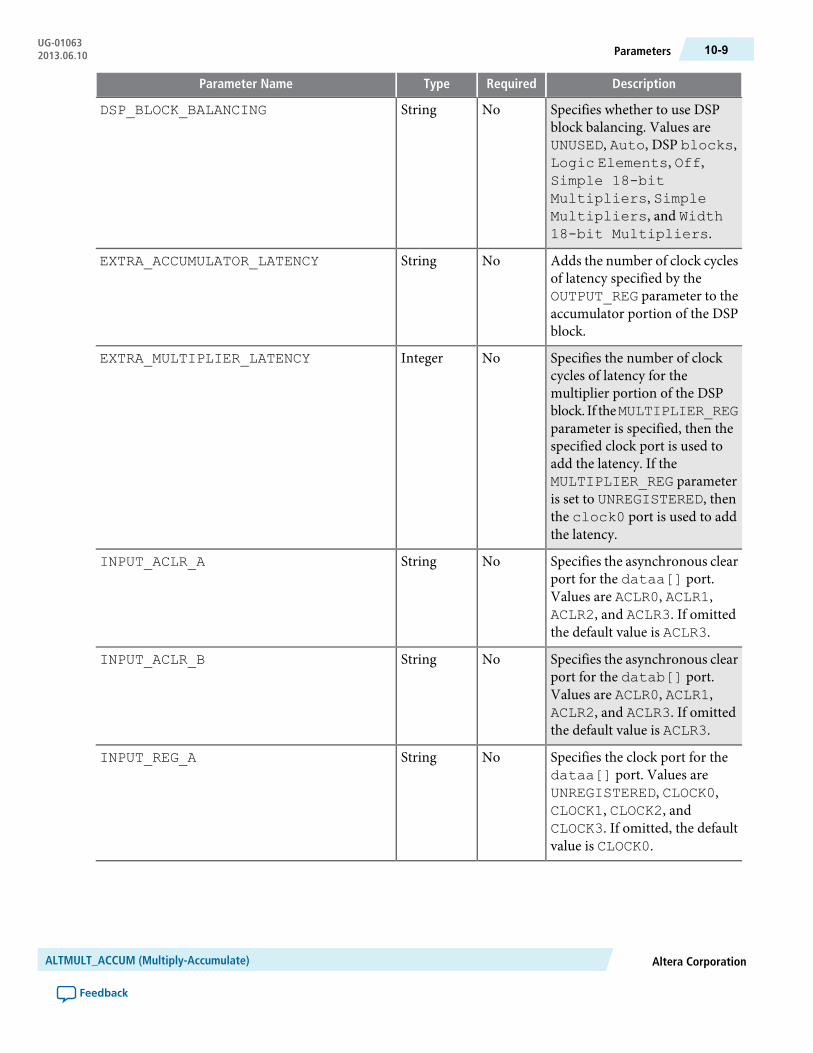
DescriptionRequiredTypeParameter Name
Specifies whether to use DSPblock balancing. Values areUNUSED, Auto, DSP blocks,Logic Elements, Off,Simple 18-bitMultipliers, SimpleMultipliers, and Width18-bit Multipliers.
NoStringDSP_BLOCK_BALANCING
Adds the number of clock cyclesof latency specified by theOUTPUT_REG parameter to theaccumulator portion of the DSPblock.
NoStringEXTRA_ACCUMULATOR_LATENCY
Specifies the number of clockcycles of latency for themultiplier portion of the DSPblock. If theMULTIPLIER_REGparameter is specified, then thespecified clock port is used toadd the latency. If theMULTIPLIER_REG parameteris set to UNREGISTERED, thenthe clock0 port is used to addthe latency.
NoIntegerEXTRA_MULTIPLIER_LATENCY
Specifies the asynchronous clearport for the dataa[] port.Values are ACLR0, ACLR1,ACLR2, and ACLR3. If omittedthe default value is ACLR3.
NoStringINPUT_ACLR_A
Specifies the asynchronous clearport for the datab[] port.Values are ACLR0, ACLR1,ACLR2, and ACLR3. If omittedthe default value is ACLR3.
NoStringINPUT_ACLR_B
Specifies the clock port for thedataa[] port. Values areUNREGISTERED, CLOCK0,CLOCK1, CLOCK2, andCLOCK3. If omitted, the defaultvalue is CLOCK0.
NoStringINPUT_REG_A
Altera CorporationALTMULT_ACCUM (Multiply-Accumulate)
Feedback
10-9ParametersUG-010632013.06.10
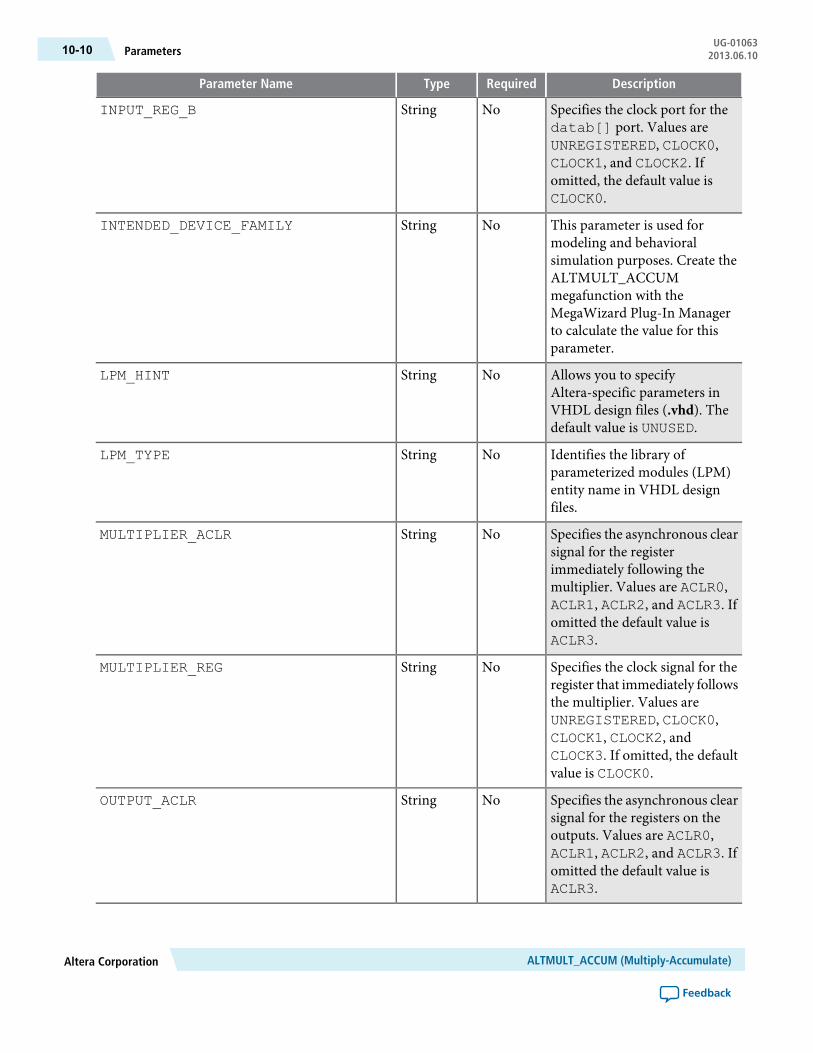
DescriptionRequiredTypeParameter Name
Specifies the clock port for thedatab[] port. Values areUNREGISTERED, CLOCK0,CLOCK1, and CLOCK2. Ifomitted, the default value isCLOCK0.
NoStringINPUT_REG_B
This parameter is used formodeling and behavioralsimulation purposes. Create theALTMULT_ACCUMmegafunction with theMegaWizard Plug-In Managerto calculate the value for thisparameter.
NoStringINTENDED_DEVICE_FAMILY
Allows you to specifyAltera-specific parameters inVHDL design files (.vhd). Thedefault value is UNUSED.
NoStringLPM_HINT
Identifies the library ofparameterized modules (LPM)entity name in VHDL designfiles.
NoStringLPM_TYPE
Specifies the asynchronous clearsignal for the registerimmediately following themultiplier. Values are ACLR0,ACLR1, ACLR2, and ACLR3. Ifomitted the default value isACLR3.
NoStringMULTIPLIER_ACLR
Specifies the clock signal for theregister that immediately followsthe multiplier. Values areUNREGISTERED, CLOCK0,CLOCK1, CLOCK2, andCLOCK3. If omitted, the defaultvalue is CLOCK0.
NoStringMULTIPLIER_REG
Specifies the asynchronous clearsignal for the registers on theoutputs. Values are ACLR0,ACLR1, ACLR2, and ACLR3. Ifomitted the default value isACLR3.
NoStringOUTPUT_ACLR
ALTMULT_ACCUM (Multiply-Accumulate)Altera Corporation
Feedback
UG-01063Parameters10-10 2013.06.10
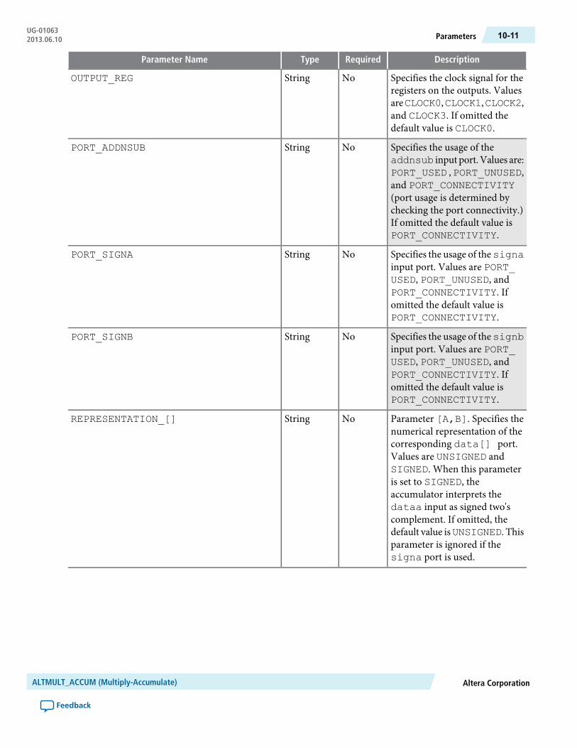
DescriptionRequiredTypeParameter Name
Specifies the clock signal for theregisters on the outputs. ValuesareCLOCK0,CLOCK1,CLOCK2,and CLOCK3. If omitted thedefault value is CLOCK0.
NoStringOUTPUT_REG
Specifies the usage of theaddnsub input port.Values are:PORT_USED , PORT_UNUSED,and PORT_CONNECTIVITY(port usage is determined bychecking the port connectivity.)If omitted the default value isPORT_CONNECTIVITY.
NoStringPORT_ADDNSUB
Specifies the usage of thesignainput port. Values are PORT_USED, PORT_UNUSED, andPORT_CONNECTIVITY. Ifomitted the default value isPORT_CONNECTIVITY.
NoStringPORT_SIGNA
Specifies the usage of thesignbinput port. Values are PORT_USED, PORT_UNUSED, andPORT_CONNECTIVITY. Ifomitted the default value isPORT_CONNECTIVITY.
NoStringPORT_SIGNB
Parameter [A,B]. Specifies thenumerical representation of thecorresponding data[] port.Values are UNSIGNED andSIGNED. When this parameteris set to SIGNED, theaccumulator interprets thedataa input as signed two'scomplement. If omitted, thedefault value isUNSIGNED. Thisparameter is ignored if thesigna port is used.
NoStringREPRESENTATION_[]
Altera CorporationALTMULT_ACCUM (Multiply-Accumulate)
Feedback
10-11ParametersUG-010632013.06.10

DescriptionRequiredTypeParameter Name
Parameter [A,B]. Specifies theasynchronous clear signal for thefirst register on thecorresponding sign[] port.Values are ACLR0, ACLR1,ACLR2, and ACLR3. If omittedthe default value is ACLR3. Thisparameter is ignored if thecorresponding sign[] port isunused.
NoStringSIGN_ACLR_[]
Parameter [A,B]. Specifies theasynchronous clear signal for thesecond register on thecorresponding sign[] port.Values are ACLR0, ACLR1,ACLR2, and ACLR3. If omittedthe default value is ACLR3. Thisparameter is ignored if thecorresponding sign[] port isunused.
NoStringSIGN_PIPELINE_ACLR_[]
Parameter [A,B]. Specifies theclock signal for the secondregister on the correspondingsign[] port. Values areUNREGISTERED, CLOCK0,CLOCK1, CLOCK2, andCLOCK3. If omitted, the defaultvalue isCLOCK0. This parameteris ignored if the correspondingsign[] port is unused.
NoStringSIGN_PIPELINE_REG_[]
Parameter [A,B]. Specifies theclock signal for the first registeron the corresponding sign[]port. Values areUNREGISTERED, CLOCK0,CLOCK1, CLOCK2, andCLOCK3. If omitted, the defaultvalue isCLOCK0. This parameteris ignored if the correspondingsign[] port is unused.
NoStringSIGN_REG_[]
Specifies the width of thedataa[] port.
YesIntegerWIDTH_A
Specifies the width of thedatab[] port.
YesIntegerWIDTH_B
ALTMULT_ACCUM (Multiply-Accumulate)Altera Corporation
Feedback
UG-01063Parameters10-12 2013.06.10
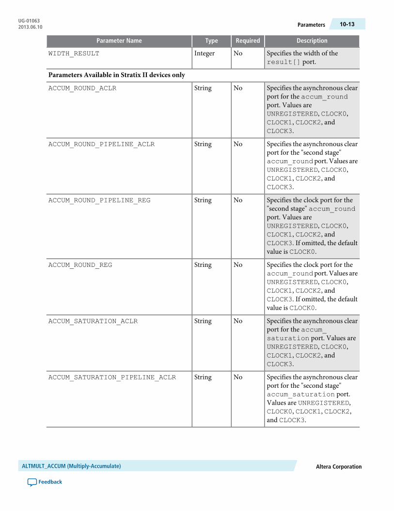
DescriptionRequiredTypeParameter Name
Specifies the width of theresult[] port.
NoIntegerWIDTH_RESULT
Parameters Available in Stratix II devices only
Specifies the asynchronous clearport for the accum_roundport. Values areUNREGISTERED, CLOCK0,CLOCK1, CLOCK2, andCLOCK3.
NoStringACCUM_ROUND_ACLR
Specifies the asynchronous clearport for the "second stage"accum_roundport. Values areUNREGISTERED, CLOCK0,CLOCK1, CLOCK2, andCLOCK3.
NoStringACCUM_ROUND_PIPELINE_ACLR
Specifies the clock port for the"second stage" accum_roundport. Values areUNREGISTERED, CLOCK0,CLOCK1, CLOCK2, andCLOCK3. If omitted, the defaultvalue is CLOCK0.
NoStringACCUM_ROUND_PIPELINE_REG
Specifies the clock port for theaccum_roundport. Values areUNREGISTERED, CLOCK0,CLOCK1, CLOCK2, andCLOCK3. If omitted, the defaultvalue is CLOCK0.
NoStringACCUM_ROUND_REG
Specifies the asynchronous clearport for the accum_saturation port. Values areUNREGISTERED, CLOCK0,CLOCK1, CLOCK2, andCLOCK3.
NoStringACCUM_SATURATION_ACLR
Specifies the asynchronous clearport for the "second stage"accum_saturation port.Values are UNREGISTERED,CLOCK0, CLOCK1, CLOCK2,and CLOCK3.
NoStringACCUM_SATURATION_PIPELINE_ACLR
Altera CorporationALTMULT_ACCUM (Multiply-Accumulate)
Feedback
10-13ParametersUG-010632013.06.10

DescriptionRequiredTypeParameter Name
Specifies the clock port for the"second stage" accum_saturation port. Values areUNREGISTERED, CLOCK0,CLOCK1, CLOCK2, andCLOCK3. If omitted, the defaultvalue is CLOCK0.
NoStringACCUM_SATURATION_PIPELINE_REG
Specifies the clock port for theaccum_saturation port.Values are UNREGISTERED,CLOCK0, CLOCK1, CLOCK2,and CLOCK3. If omitted, thedefault value is CLOCK0.
NoStringACCUM_SATURATION_REG
Specifies accumulator rounding.Values are NO, YES, andVARIABLE. If omitted thedefault value is NO.
NoStringACCUMULATOR_ROUNDING
Specifies accumulator saturation.Values are NO, YES, andVARIABLE. If omitted thedefault value is NO.
NoStringACCUMULATOR_SATURATION
Specifies the asynchronous clearport for themult_round port.Values are UNREGISTERED,CLOCK0, CLOCK1, CLOCK2,and CLOCK3. If omitted, thedefault value isUNREGISTERED.
NoStringMULT_ROUND_ACLR
Specifies the clock port for themult_round port. Values areUNREGISTERED, CLOCK0,CLOCK1, CLOCK2, andCLOCK3. If omitted, the defaultvalue is CLOCK0.
NoStringMULT_ROUND_REG
Specifies the asynchronous clearport for the mult_saturation port. Values areUNREGISTERED, CLOCK0,CLOCK1, CLOCK2, andCLOCK3. If omitted, the defaultvalue is UNREGISTERED.
NoStringMULT_SATURATION_ACLR
ALTMULT_ACCUM (Multiply-Accumulate)Altera Corporation
Feedback
UG-01063Parameters10-14 2013.06.10
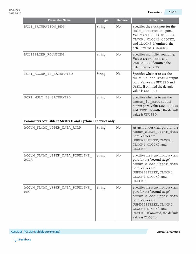
DescriptionRequiredTypeParameter Name
Specifies the clock port for themult_saturation port.Values are UNREGISTERED,CLOCK0, CLOCK1, CLOCK2,and CLOCK3. If omitted, thedefault value is CLOCK0.
NoStringMULT_SATURATION_REG
Specifies multiplier rounding.Values are NO, YES, andVARIABLE. If omitted thedefault value is NO.
NoStringMULTIPLIER_ROUNDING
Specifies whether to use themult_is_saturatedoutputport. Values are UNUSED andUSED. If omitted the defaultvalue is UNUSED.
NoStringPORT_ACCUM_IS_SATURATED
Specifies whether to use theaccum_is_saturatedoutput port. Values areUNUSEDandUSED. If omitted the defaultvalue is UNUSED.
NoStringPORT_MULT_IS_SATURATED
Parameters Available in Stratix II and Cyclone II devices only
Asynchronous clear port for theaccum_sload_upper_dataport. Values areUNREGISTERED, CLOCK0,CLOCK1, CLOCK2, andCLOCK3.
NoStringACCUM_SLOAD_UPPER_DATA_ACLR
Specifies the asynchronous clearport for the "second stage"accum_sload_upper_dataport. Values areUNREGISTERED, CLOCK0,CLOCK1, CLOCK2, andCLOCK3.
NoStringACCUM_SLOAD_UPPER_DATA_PIPELINE_ACLR
Specifies the asynchronous clearport for the "second stage"accum_sload_upper_dataport. Values areUNREGISTERED, CLOCK0,CLOCK1, CLOCK2, andCLOCK3. If omitted, the defaultvalue is CLOCK0.
NoStringACCUM_SLOAD_UPPER_DATA_PIPELINE_REG
Altera CorporationALTMULT_ACCUM (Multiply-Accumulate)
Feedback
10-15ParametersUG-010632013.06.10
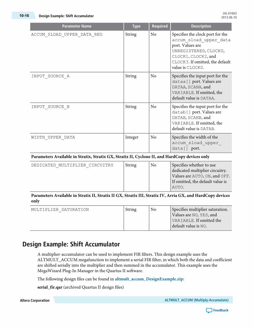
DescriptionRequiredTypeParameter Name
Specifies the clock port for theaccum_sload_upper_dataport. Values areUNREGISTERED, CLOCK0,CLOCK1, CLOCK2, andCLOCK3. If omitted, the defaultvalue is CLOCK0.
NoStringACCUM_SLOAD_UPPER_DATA_REG
Specifies the input port for thedataa[] port. Values areDATAA, SCANA, andVARIABLE. If omitted, thedefault value is DATAA.
NoStringINPUT_SOURCE_A
Specifies the input port for thedatab[] port. Values areDATAB, SCANB, andVARIABLE. If omitted, thedefault value is DATAB.
NoStringINPUT_SOURCE_B
Specifies the width of theaccum_sload_upper_data[] port.
NoIntegerWIDTH_UPPER_DATA
Parameters Available in Stratix, Stratix GX, Stratix II, Cyclone II, and HardCopy devices only
Specifies whether to usededicated multiplier circuitry.Values are AUTO, ON, and OFF.If omitted, the default value isAUTO.
NoStringDEDICATED_MULTIPLIER_CIRCUITRY
Parameters Available in Stratix II, Stratix II GX, Stratix III, Stratix IV, Arria GX, and HardCopy devicesonly
Specifies multiplier saturation.Values are NO, YES, andVARIABLE. If omitted thedefault value is NO.
NoStringMULTIPLIER_SATURATION
Design Example: Shift AccumulatorA multiplier-accumulator can be used to implement FIR filters. This design example uses theALTMULT_ACCUM megafunction to implement a serial FIR filter, in which both the data and coefficientare shifted serially into the multiplier and then summed in the accumulator. This example uses theMegaWizard Plug-In Manager in the Quartus II software.
The following design files can be found in altmult_accum_DesignExample.zip:
serial_fir.qar (archived Quartus II design files)
ALTMULT_ACCUM (Multiply-Accumulate)Altera Corporation
Feedback
UG-01063Design Example: Shift Accumulator10-16 2013.06.10
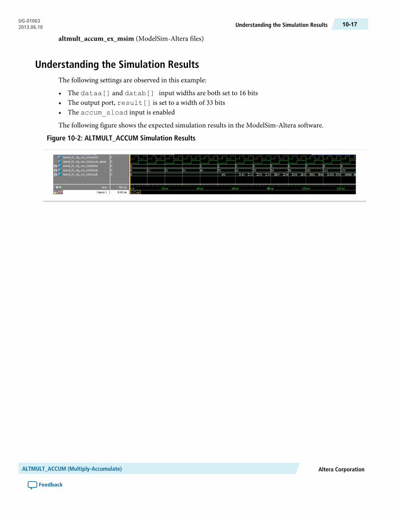
altmult_accum_ex_msim (ModelSim-Altera files)
Understanding the Simulation ResultsThe following settings are observed in this example:
• The dataa[] and datab[] input widths are both set to 16 bits• The output port, result[] is set to a width of 33 bits• The accum_sload input is enabled
The following figure shows the expected simulation results in the ModelSim-Altera software.
Figure 10-2: ALTMULT_ACCUM Simulation Results
Altera CorporationALTMULT_ACCUM (Multiply-Accumulate)
Feedback
10-17Understanding the Simulation ResultsUG-010632013.06.10

11ALTMULT_ADD (Multiply-Adder)
2013.06.10UG-01063 Subscribe Feedback
The ALTMULT_ADD megafunction allows you to implement a multiplier-adder.
• The ALTMULT_ADD megafunction is scheduled for product obsolescence and discontinuedsupport for Arria V, Cyclone V, and Stratix V devices, with last ship date the Quartus II software13.0 release.
• Therefore, for Arria V, Cyclone V, and Stratix V devices, Altera recommends using theALTERA_MULT_ADD (Multiply-Adder) on page 8-1 instead.
Note:
The following figure shows the ports for the ALTMULT_ADD megafunction.
ISO9001:2008Registered
© 2013 Altera Corporation. All rights reserved. ALTERA, ARRIA, CYCLONE, HARDCOPY, MAX, MEGACORE, NIOS, QUARTUS and STRATIXwords and logos are trademarks of Altera Corporation and registered in the U.S. Patent and Trademark Office and in other countries. All other wordsand logos identified as trademarks or service marks are the property of their respective holders as described at www.altera.com/common/legal.html.Altera warrants performance of its semiconductor products to current specifications in accordance with Altera's standard warranty, but reserves theright to make changes to any products and services at any time without notice. Altera assumes no responsibility or liability arising out of the applicationor use of any information, product, or service described herein except as expressly agreed to in writing by Altera. Altera customers are advised toobtain the latest version of device specifications before relying on any published information and before placing orders for products or services.
www.altera.com
101 Innovation Drive, San Jose, CA 95134

Figure 11-1: ALTMULT_ADD Ports
dataa[]
inst
ALTMULT_ADD
datab[]signa scanouta[]
signb
scanoutb[]
result[]
overflow
mult_is_saturated
chain_out_sat_overflow
aclr0
aclr1
aclr2
aclr3
datac[]
coefsel1[]
addnsub1addnsub3
clock0ena0clock1ena1clock2ena2clock3ena3output_roundoutput_saturatechainout_roundchainout_saturate
zero_chainoutaccum_sloadzero_loopbackchainin[]shift_rightrotate
addsub1_roundaddsub3_round
mult[]_roundmult[]_saturation
coefsel2[]
coefsel3[]
coefsel0[]
A multiplier-adder accepts pairs of inputs, multiplies the values together and then adds to or subtracts fromthe products of all other pairs.
The ALTMULT_ADD megafunction also offers many variations in dedicated DSP block circuitry. Datainput sizes of up to 18 bits are accepted. Because the DSP blocks allow for one or two levels of 2-input addor subtract operations on the product, this function creates up to four multipliers.
Stratix III and Stratix IV device families use two MAC blocks (mac_mult and mac_out) to form DSPoperations, multiply and add. For Stratix V devices, the multiplier blocks and adder/accumulator block iscombined in a single MAC block.
The multipliers and adders of the ALTMULT_ADD megafunction are placed in the dedicated DSP blockcircuitry of the Stratix devices. If all of the input data widths are 9-bits wide or smaller, the function uses the9 × 9-bit input multiplier configuration in the DSP block. If not, the DSP block uses 18 × 18-bit inputmultipliers to process data with widths between 10 bits and 18 bits. If multiple ALTMULT_ADDmegafunctions occur in a design, the functions are distributed to as many different DSP blocks as possibleso that routing to these blocks is more flexible. Fewer multipliers per DSP block allow more routing choicesinto the block by minimizing paths to the rest of the device.
ALTMULT_ADD (Multiply-Adder)Altera Corporation
Feedback
UG-01063ALTMULT_ADD (Multiply-Adder)11-2 2013.06.10
The registers and extra pipeline registers for the following signals are also placed inside the DSP block:
• Data input• Signed or unsigned select• Add or subtract select• Products of multipliers
In the case of the output result, the first register is placed in theDSP block. However the extra latency registersare placed in logic elements outside the block. Peripheral to the DSP block, including data inputs to themultiplier, control signal inputs, and outputs of the adder, use regular routing to communicate with the restof the device. All connections in the function use dedicated routing inside the DSP block. This dedicatedrouting includes the shift register chains when you select the option to shift a multiplier's registered inputdata from one multiplier to an adjacent multiplier.
For more information about DSP blocks in any of the Stratix, Stratix GX, and Arria GX device series, referto the DSP Blocks chapter of the respective handbooks on the Literature and Technical Documentationpage.
For more information about the embedded memory blocks in any of the Stratix, Stratix GX, and Arria GXdevice series, refer to the TriMatrix Embedded Memory Blocks chapter of the respective handbooks on theLiterature and Technical Documentation page.
For more information on embedded multiplier blocks in the Cyclone II and Cyclone III devices, refer to theDSP Blocks chapter of the respective handbooks on the Literature and Technical Documentation page.
For more information about implementing multipliers using DSP and memory blocks in Altera FPGAs,refer to AN 306: Implementing Multipliers in FPGA Devices.
FeaturesThe ALTMULT_ADD megafunction offers the following features:
• Generates a multiplier to perform multiplication operations of two complex numbers• Supports data widths of 1– 256 bits• Supports signed and unsigned data representation format• Supports pipelining with configurable output latency• Provides a choice of implementation in dedicated DSP block circuitry or logic elements (LEs)• Provides an option to dynamically switch between signed and unsigned data support• Provides an option to dynamically switch between add and subtract operation• Provides an option to set up data shifting register chains• Supports hardware saturation and rounding (for selected device families only)• Supports optional asynchronous clear and clock enable input ports• The pre-adder, coefficient storage and systolic delay register features are added to maximize flexibility.
The following sections describe the new features.
Altera CorporationALTMULT_ADD (Multiply-Adder)
Feedback
11-3FeaturesUG-010632013.06.10
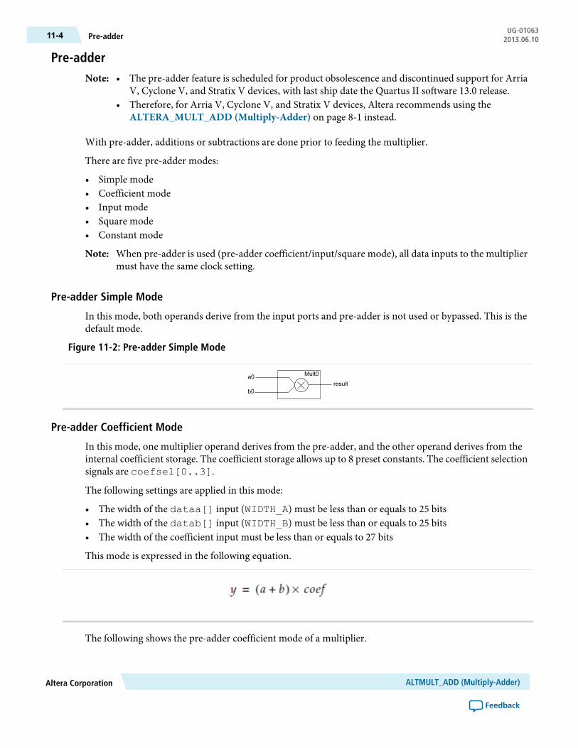
Pre-adder• The pre-adder feature is scheduled for product obsolescence and discontinued support for Arria
V, Cyclone V, and Stratix V devices, with last ship date the Quartus II software 13.0 release.• Therefore, for Arria V, Cyclone V, and Stratix V devices, Altera recommends using the
ALTERA_MULT_ADD (Multiply-Adder) on page 8-1 instead.
Note:
With pre-adder, additions or subtractions are done prior to feeding the multiplier.
There are five pre-adder modes:
• Simple mode• Coefficient mode• Input mode• Square mode• Constant mode
When pre-adder is used (pre-adder coefficient/input/square mode), all data inputs to the multipliermust have the same clock setting.
Note:
Pre-adder Simple Mode
In this mode, both operands derive from the input ports and pre-adder is not used or bypassed. This is thedefault mode.
Figure 11-2: Pre-adder Simple Mode
a0
b0
Mult0
result
Pre-adder Coefficient Mode
In this mode, one multiplier operand derives from the pre-adder, and the other operand derives from theinternal coefficient storage. The coefficient storage allows up to 8 preset constants. The coefficient selectionsignals are coefsel[0..3].
The following settings are applied in this mode:
• The width of the dataa[] input (WIDTH_A) must be less than or equals to 25 bits• The width of the datab[] input (WIDTH_B) must be less than or equals to 25 bits• The width of the coefficient input must be less than or equals to 27 bits
This mode is expressed in the following equation.
The following shows the pre-adder coefficient mode of a multiplier.
ALTMULT_ADD (Multiply-Adder)Altera Corporation
Feedback
UG-01063Pre-adder11-4 2013.06.10

Figure 11-3: Pre-adder Coefficient Mode
a0
b0
Mult0
result
coef
+/-
Preadder
coefsel0
Pre-adder Input Mode
In this mode, one multiplier operand derives from the pre-adder, and the other operand derives from thedatac[] input port.
The following settings are applied in this mode:
• The width of the dataa[] input (WIDTH_A) must be less than or equals to 25 bits• The width of the datab[] input (WIDTH_B) must be less than or equals to 25 bits• The width of the datac[] input (WIDTH_C) must be less than or equals to 22 bits• The number of multipliers must be set to 1• All input registers must be registered with the same clock
This mode is expressed in the following equation.
The following shows the pre-adder input mode of a multiplier.
Figure 11-4: Pre-adder Input Mode
a0
b0
Mult0
result
c0
+/-
Pre-adder Square Mode
In this mode, both multiplier operands derive from the pre-adder.
The following settings are applied in this mode:
• The width of the dataa[] input (WIDTH_A) must be less than or equals to 17 bits• The width of the datab[] input (WIDTH_B) must be less than or equals to 17 bits• The number of multipliers must be set to 2
This mode is expressed in the following equation.
Altera CorporationALTMULT_ADD (Multiply-Adder)
Feedback
11-5Pre-adder Input ModeUG-010632013.06.10

The following shows the pre-adder square mode of two multipliers.
Figure 11-5: Pre-adder Square Mode
a0
b0
a1
b1
Mult0
Mult1result
+/-
+/-
Pre-adder Constant Mode
In this mode, one multiplier operand derives from the input port, and the other operand derives from theinternal coefficient storage. The coefficient storage allows up to 8 preset constants. The coefficient selectionsignals are coefsel[0..3].
The following settings are applied in this mode:
• The width of the dataa[] input (WIDTH_A) must be less than or equals to 27 bits• The width of the coefficient input must be less than or equals to 27 bits• The datab[] port must be disconnected
This mode is expressed in the following equation.
The following figure shows the pre-adder constant mode of a multiplier.
Figure 11-6: Pre-adder Constant Mode
a0
Mult0
result
coef
coefsel0
Systolic Delay RegisterIn a systolic architecture, the input data is fed into a cascade of registers acting as a data buffer. Each registerdelivers an input sample to a multiplier where it is multiplied by the respective coefficient. The chain adderstores the gradually combined results from the multiplier and the previously registered result from thechainin[] input port to form the final result. Each multiply-add element must be delayed by a single
ALTMULT_ADD (Multiply-Adder)Altera Corporation
Feedback
UG-01063Pre-adder Constant Mode11-6 2013.06.10

cycle so that the results synchronize appropriately when added together. Each successive delay is used toaddress both the coefficient memory and the data buffer of their respective multiply-add elements. Forexample, a single delay for the second multiply add element, two delays for the third multiply-add element,and so on.
Figure 11-7: Systolic Registers
x(t)
c(0) c(1) c(2)
y(t)
c(N-1)
Systolic registers
S-1 S-1 S-1 S-1 S-1 S-1
S-1 S-1 S-1S-1
x(t) represents the results from a continuous stream of input samples and y(t) represents the summation ofa set of input samples, and in time, multiplied by their respective coefficients. Both the input and outputresults flow from left to right. The c(0) to c(N-1) denotes the coefficients. The systolic delay registers aredenoted by S-1, whereas the –1 represents a single clock delay. Systolic delay registers are added at the inputsand outputs for pipelining in away that ensures the results from themultiplier operand and the accumulatedsums stay in synch. This processing element is replicated to form a circuit that computes the filtering function.This function is expressed in the following equation.
N represents the number of cycles of data that has entered into the accumulator, y(t) represents the outputat time t,A(t) represents the input at time t, andB(i) are the coefficients. The t and i in the equation correspondto a particular instant in time, so to compute the output sample y(t) at time t, a group of input samples at Ndifferent points in time, or A(n), A(n-1), A(n-2), … A(n-N+1) is required. The group of N input samplesare multiplied by N coefficients and summed together to form the final result y.
The systolic register architecture is available only for sum-of-2 and sum-of-4 modes.
The following figure shows the systolic delay register implementation of 2 multipliers.
Altera CorporationALTMULT_ADD (Multiply-Adder)
Feedback
11-7Systolic Delay RegisterUG-010632013.06.10

Figure 11-8: Systolic Delay Register Implementation of 2 Multipliers
a0
b0
Mult0
result
chainin
a1
b1
Mult1
+/-
+/-
Systolic registers
The sum of two multipliers is expressed in the following equation.
The following figure shows the systolic delay register implementation of 4 multipliers.
ALTMULT_ADD (Multiply-Adder)Altera Corporation
Feedback
UG-01063Systolic Delay Register11-8 2013.06.10

Figure 11-9: Systolic Delay Register Implementation of 4 Multipliers
a0
b0
Mult0
result
chainin
chainin
a1
b1
Mult1
a2
b2
Mult2
a3
b3
Mult3
result
+/-
+/-
+/-
+/-
Systolic registers
The sum of four multipliers is expressed in the following equation.
Figure 11-10: Sum of 4 Multipliers
The following lists the advantages of systolic register implementation:
• Reduces DSP resource usage• Enables efficient mapping in the DSP block using the chain adder structure
The systolic delay implementation is only available for the following pre-adder modes:
• Pre-adder coefficient mode• Pre-adder simple mode• Pre-adder constant mode
Altera CorporationALTMULT_ADD (Multiply-Adder)
Feedback
11-9Systolic Delay RegisterUG-010632013.06.10

Pre-load ConstantThe pre-load constant controls the accumulator operand and complements the accumulator feedback. Thevalid LOADCONST_VALUE ranges from 0–64. The constant value is equal to 2N, where N =LOADCONST_VALUE. When the LOADCONST_VALUE is set to 64, the constant value is equal to 0. Thisfunction can be used as biased rounding.
The following figure shows the pre-load constant implementation.
Figure 11-11: Pre-load Constant
a0
b0
a1
b1
Mult0
Mult1
Accumulator feedback
accum_sload
constant
result
+/-
+/-
Refer to the following megafunctions in this user guide for other multiplier implementations:
• ALTMULT_ACCUM (Multiply-Accumulate)• ALTMEMMULT (Memory-based Constant Coefficient Multiplier)• LPM_MULT (Multiplier)
Double AccumulatorThe double accumulator feature adds an additional register in the accumulator feedback path. The doubleaccumulator register follows the output register, which includes the clock, clock enable, and aclr. Theadditional accumulator register returns result with a one-cycle delay. This feature enables you to have twoaccumulator channels with the same resource count.
The following figure shows the double accumulator implementation.
ALTMULT_ADD (Multiply-Adder)Altera Corporation
Feedback
UG-01063Pre-load Constant11-10 2013.06.10
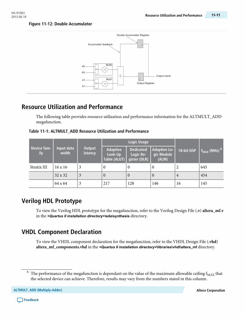
Figure 11-12: Double Accumulator
a0
b0
a1
b1
Mult0
Mult1
Accumulator feedback
Output result
+/-
+/-
Double Accumulator Register
Output Register
Resource Utilization and PerformanceThe following table provides resource utilization and performance information for the ALTMULT_ADDmegafunction.
Table 11-1: ALTMULT_ADD Resource Utilization and Performance
fMAX (MHz) 818-bit DSP
Logic Usage
Outputlatency
Input datawidth
Device fam-ily
Adaptive Lo-gic Module
(ALM)
DedicatedLogic Re-
gister (DLR)
AdaptiveLook-Up
Table (ALUT)
6452000316 x 16Stratix III
4544000332 x 32
14516146128217364 x 64
Verilog HDL PrototypeTo view the Verilog HDL prototype for the megafunction, refer to the Verilog Design File (.v) altera_mf.vin the <Quartus II installation directory>\eda\synthesis directory.
VHDL Component DeclarationTo view the VHDL component declaration for the megafunction, refer to the VHDL Design File (.vhd)altera_mf_components.vhd in the <Quartus II installation directory>\libraries\vhdl\altera_mf directory.
8 The performance of the megafunction is dependant on the value of the maximum allowable ceiling fMAX thatthe selected device can achieve. Therefore, results may vary from the numbers stated in this column.
Altera CorporationALTMULT_ADD (Multiply-Adder)
Feedback
11-11Resource Utilization and PerformanceUG-010632013.06.10

VHDL LIBRARY_USE DeclarationThe VHDL LIBRARY-USE declaration is not required if you use the VHDL Component Declaration.
LIBRARY altera_mf;USE altera_mf.altera_mf_components.all;
PortsThe following tables list the input and output ports for the ALTMULT_ADD megafunction.
Table 11-2: ALTMULT_ADD Megafunction Input Ports
DescriptionRequiredPort Name
Data input to the multiplier. Input port [NUMBER_OF_MULTIPLIERS* WIDTH_A - 1..0] wide.
Yesdataa[]
Data input to the multiplier. Input port [NUMBER_OF_MULTIPLIERS* WIDTH_B - 1..0] wide.
Yesdatab[]
Clock input port [0..3] to the corresponding register. This port can beused by any register in the megafunction.
Noclock[]
Input port[0..3]. Asynchronous clear input to the corresponding register.Noaclr[]
Input port [0..3]. Clock enable for the corresponding clock[] port.Noena[]
Specifies the numerical representation of the dataa[] port. If the signaport is high, the multiplier treats the dataa[] port as a signed two'scomplement number. If the signa port is low, the multiplier treats thedataa[] port as an unsigned number.
Nosigna
Specifies the numerical representation of the datab[] port. If the signbport is high, the multiplier treats the datab[] port as a signed two'scomplement number. If the signb port is low, the multiplier treats thedatab[] port as an unsigned number.
Nosignb
Ports Available in Stratix II devices only
Input for scan chain A. Input port [WIDTH_A - 1..0]wide. When theINPUT_SOURCE_A parameter has a value of SCANA or VARIABLE, thescanina[] port is required. Do not use scanina[] and scaninb[]simultaneously.
Noscanina[]
Input for scan chain B. Input port [WIDTH_B - 1..0]wide. When theINPUT_SOURCE_A parameter has a value of SCANB or VARIABLE, thescaninb[] port is required. Do not use scanina[] and scaninb[]simultaneously.
Noscaninb[]
Input source for scan chain A.Nosourcea
ALTMULT_ADD (Multiply-Adder)Altera Corporation
Feedback
UG-01063VHDL LIBRARY_USE Declaration11-12 2013.06.10

DescriptionRequiredPort Name
Input source for scan chain B.Nosourceb
Controls the functionality of the adder. If the addnsub1 port is high, theadder performs an add function. If the addnsub1 port is low, the adderperforms a subtract function.
Noaddnsub1
Enables addition or subtraction for the second multiplier.Noaddnsub1_round
Controls the functionality of the adder. If the addnsub3 port is high, theadder performs an add function. If the addnsub3 port is low, the adderperforms a subtract function.
Noaddnsub3
Enables addition or subtraction for the fourth multiplier.Noaddnsub3_round
Enables rounding for the first and second multiplier [01], or the thirdand fourth multiplier [23]. Port is required when the correspondingMULTIPLIER[]_ROUNDING parameter has a value of VARIABLE.
Nomult[]_round
Enables saturation for the first and second multiplier [01], or the thirdand fourth multiplier [23]. Port is required when the correspondingMULTIPLIER[]_SATURATION parameter has a value of VARIABLE.
Nomult[]_saturation
Ports Available in Stratix III and Stratix IV devices only
Enables dynamically controlled output rounding. When OUTPUT_ROUNDING is set to VARIABLE, output_round enables the final adderstage of rounding.
Nooutput_round
Enables dynamically controlled output saturation. When OUTPUT_SATURATION is set toVARIABLE,output_saturate enables the finaladder stage of saturation.
Nooutput_saturate
Enables dynamically controlled chainout stage rounding. WhenCHAINOUT_ROUNDING is set toVARIABLE,chainout_round enablesthe chainout stage of rounding.
Nochainout_round
Enables dynamically controlled chainout stage saturation. WhenCHAINOUT_SATURATION is set toVARIABLE,chainout_saturateenables the chainout stage of saturation.
Nochainout_saturate
Dynamically specifies whether the chainout value is zero.Nozero_chainout
Dynamically specifies whether the loopback value is zero.Nozero_loopback
Dynamically specifies whether the accumulator value is zero.Noaccum_sload
Adder result input bus from the preceding stage. Input port [WIDTH_CHAININ - 1..0] wide.
Nochainin
Specifies dynamically controlled port rotation in shift mode.Norotate
Specifies dynamically controlled port shift right or left in shift mode. Valuesare 0 and 1. A value of 0 specifies a shift to the left, a value of 1 specifies ashift to the right.
Noshift_right
Altera CorporationALTMULT_ADD (Multiply-Adder)
Feedback
11-13PortsUG-010632013.06.10

Table 11-3: ALTMULT_ADD Megafunction Output Ports
DescriptionRequiredPort Name
Multiplier output port. Output port [WIDTH_RESULT - 1..0]wide.
Yesresult[]
Overflow flag. If output_saturation is enabled, overflow flag isset.
Nooverflow
Output of scan chain A. Output port [WIDTH_A - 1..0] wide.When designing with Stratix III devices, port cannot be selected whenscaninb[] is in use. Do not use scanina[] and scaninb[]simultaneously.
Noscanouta[]
Output of scan chain B. Output port [WIDTH_B - 1..0] wide.When designing with Stratix III devices, port cannot be selected whenscanina[] is in use. Do not use scanina[] and scaninb[]simultaneously.
Noscanoutb[]
Ports Available in Stratix II devices only
Signal indicating saturation of the first multiplier. This port is requiredwhen PORT_MULT0_IS_SATURATED has a value of USED.
Nomult0_is_saturated
Signal indicating saturation of the second multiplier. This port isrequiredwhenPORT_MULT1_IS_SATURATED has a value ofUSED.
Nomult1_is_saturated
Signal indicating saturation of the thirdmultiplier. This port is requiredwhen PORT_MULT2_IS_SATURATED has a value of USED.
Nomult2_is_saturated
Signal indicating saturation of the fourthmultiplier. This port is requiredwhen PORT_MULT3_IS_SATURATED has a value of USED.
Nomult3_is_saturated
Ports Available in Stratix III and Stratix IV devices only
Overflow flag for the chainout saturation.Nochainout_sat_overflow
ParametersThe following table lists the parameters for the ALTMULT_ADD megafunction.
For Stratix III, Stratix IV, and Arria II GX devices, when the output result is > 36 bits (for example,when you set width_a=18 and width_b=18), the option for rounding and saturation is disabled.This is because additional logic is used to generate the MSB.
Note:
ALTMULT_ADD (Multiply-Adder)Altera Corporation
Feedback
UG-01063Parameters11-14 2013.06.10

Table 11-4: ALTMULT_ADD Megafunction Parameters
DescriptionRe-quired
TypeParameter Name
Number of multipliers to be addedtogether. Values are 1 up to 4.
YesIntegerNUMBER_OF_MULTIPLIERS
Width of the dataa[] port.YesIntegerWIDTH_A
Width of the datab[] port.YesIntegerWIDTH_B
Width of theresult[]port. Valueincludes all bits before rounding andsaturation.
YesIntegerWIDTH_RESULT
Specifies the clock port for thedataa[] operand of the firstmultiplier. Values areUNREGISTERED, CLOCK0,CLOCK1, CLOCK2, and CLOCK3. Ifomitted, the default value isCLOCK0. For Stratix III devices,INPUT_REGISTER_A0must havesimilar values with INPUT_REGISTER_A[1..3].
NoStringINPUT_REGISTER_A0
Specifies the clock port for thedataa[] operand of the secondmultiplier. Values areUNREGISTERED, CLOCK0,CLOCK1, CLOCK2, and CLOCK3. Ifomitted, the default value isCLOCK0. For Stratix III devices, thevalues for INPUT_REGISTER_A[1..3]must be set similar to thevalue of INPUT_REGISTER_A0.
NoStringINPUT_REGISTER_A1
Specifies the clock port for thedataa[] operand of the thirdmultiplier. Values areUNREGISTERED, CLOCK0,CLOCK1, CLOCK2, and CLOCK3. Ifomitted, the default value isCLOCK0. For Stratix III devices, thevalues for INPUT_REGISTER_A[1..3]must be set similar to thevalue of INPUT_REGISTER_A0.
NoStringINPUT_REGISTER_A2
Altera CorporationALTMULT_ADD (Multiply-Adder)
Feedback
11-15ParametersUG-010632013.06.10
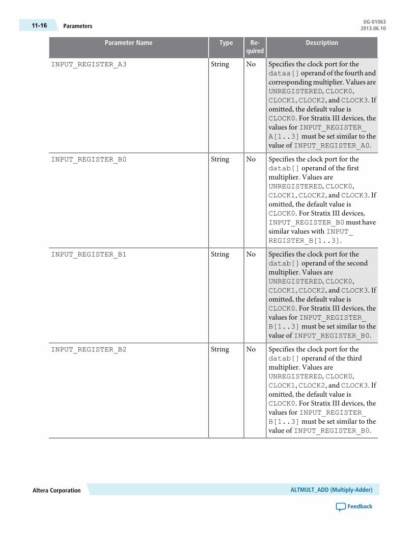
DescriptionRe-quired
TypeParameter Name
Specifies the clock port for thedataa[] operand of the fourth andcorrespondingmultiplier. Values areUNREGISTERED, CLOCK0,CLOCK1, CLOCK2, and CLOCK3. Ifomitted, the default value isCLOCK0. For Stratix III devices, thevalues for INPUT_REGISTER_A[1..3]must be set similar to thevalue of INPUT_REGISTER_A0.
NoStringINPUT_REGISTER_A3
Specifies the clock port for thedatab[] operand of the firstmultiplier. Values areUNREGISTERED, CLOCK0,CLOCK1, CLOCK2, and CLOCK3. Ifomitted, the default value isCLOCK0. For Stratix III devices,INPUT_REGISTER_B0must havesimilar values with INPUT_REGISTER_B[1..3].
NoStringINPUT_REGISTER_B0
Specifies the clock port for thedatab[] operand of the secondmultiplier. Values areUNREGISTERED, CLOCK0,CLOCK1, CLOCK2, and CLOCK3. Ifomitted, the default value isCLOCK0. For Stratix III devices, thevalues for INPUT_REGISTER_B[1..3]must be set similar to thevalue of INPUT_REGISTER_B0.
NoStringINPUT_REGISTER_B1
Specifies the clock port for thedatab[] operand of the thirdmultiplier. Values areUNREGISTERED, CLOCK0,CLOCK1, CLOCK2, and CLOCK3. Ifomitted, the default value isCLOCK0. For Stratix III devices, thevalues for INPUT_REGISTER_B[1..3]must be set similar to thevalue of INPUT_REGISTER_B0.
NoStringINPUT_REGISTER_B2
ALTMULT_ADD (Multiply-Adder)Altera Corporation
Feedback
UG-01063Parameters11-16 2013.06.10

DescriptionRe-quired
TypeParameter Name
Specifies the clock port for thedatab[] operand of the fourth andcorrespondingmultiplier. Values areUNREGISTERED, CLOCK0,CLOCK1, CLOCK2, and CLOCK3. Ifomitted, the default value isCLOCK0. For Stratix III devices, thevalues for INPUT_REGISTER_B[1..3]must be set similar to thevalue of INPUT_REGISTER_B0.
NoStringINPUT_REGISTER_B3
Specifies the asynchronous clear forthe dataa[] operand of the firstmultiplier. Values are ACLR0,ACLR1, ACLR2, and ACLR3. Ifomitted and correspondingINPUT_REGISTER_A[] is used, the defaultvalue is ACLR3.
NoStringINPUT_ACLR_A0
Specifies the asynchronous clear forthedataa[] operand of the secondmultiplier. Values are ACLR0,ACLR1, ACLR2, and ACLR3. Ifomitted and correspondingINPUT_REGISTER_A[] is used, the defaultvalue is ACLR3.
NoStringINPUT_ACLR_A1
Specifies the asynchronous clear forthe dataa[] operand of the thirdmultiplier. Values are ACLR0,ACLR1, ACLR2, and ACLR3. Ifomitted and correspondingINPUT_REGISTER_A[] is used, the defaultvalue is ACLR3.
NoStringINPUT_ACLR_A2
Specifies the asynchronous clear forthe dataa[] operand of the fourthand correspondingmultiplier.Valuesare ACLR0, ACLR1, ACLR2, andACLR3. If omitted andcorrespondingINPUT_REGISTER_A[] is used, the default value isACLR3.
NoStringINPUT_ACLR_A3
Altera CorporationALTMULT_ADD (Multiply-Adder)
Feedback
11-17ParametersUG-010632013.06.10
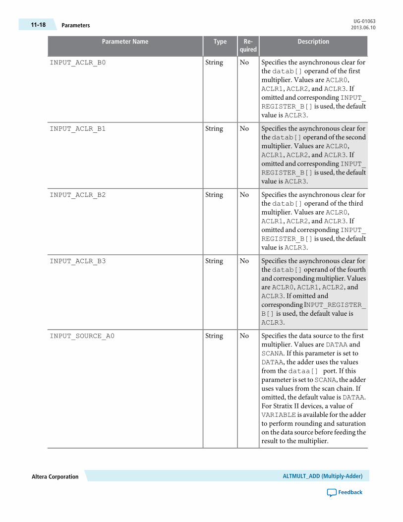
DescriptionRe-quired
TypeParameter Name
Specifies the asynchronous clear forthe datab[] operand of the firstmultiplier. Values are ACLR0,ACLR1, ACLR2, and ACLR3. Ifomitted and correspondingINPUT_REGISTER_B[] is used, the defaultvalue is ACLR3.
NoStringINPUT_ACLR_B0
Specifies the asynchronous clear forthedatab[] operand of the secondmultiplier. Values are ACLR0,ACLR1, ACLR2, and ACLR3. Ifomitted and correspondingINPUT_REGISTER_B[] is used, the defaultvalue is ACLR3.
NoStringINPUT_ACLR_B1
Specifies the asynchronous clear forthe datab[] operand of the thirdmultiplier. Values are ACLR0,ACLR1, ACLR2, and ACLR3. Ifomitted and correspondingINPUT_REGISTER_B[] is used, the defaultvalue is ACLR3.
NoStringINPUT_ACLR_B2
Specifies the asynchronous clear forthe datab[] operand of the fourthand correspondingmultiplier.Valuesare ACLR0, ACLR1, ACLR2, andACLR3. If omitted andcorresponding INPUT_REGISTER_B[] is used, the default value isACLR3.
NoStringINPUT_ACLR_B3
Specifies the data source to the firstmultiplier. Values are DATAA andSCANA. If this parameter is set toDATAA, the adder uses the valuesfrom the dataa[] port. If thisparameter is set toSCANA, the adderuses values from the scan chain. Ifomitted, the default value is DATAA.For Stratix II devices, a value ofVARIABLE is available for the adderto perform rounding and saturationon the data source before feeding theresult to the multiplier.
NoStringINPUT_SOURCE_A0
ALTMULT_ADD (Multiply-Adder)Altera Corporation
Feedback
UG-01063Parameters11-18 2013.06.10
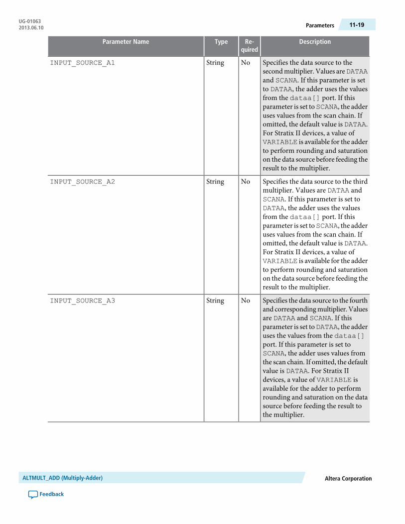
DescriptionRe-quired
TypeParameter Name
Specifies the data source to thesecondmultiplier. Values areDATAAand SCANA. If this parameter is setto DATAA, the adder uses the valuesfrom the dataa[] port. If thisparameter is set toSCANA, the adderuses values from the scan chain. Ifomitted, the default value is DATAA.For Stratix II devices, a value ofVARIABLE is available for the adderto perform rounding and saturationon the data source before feeding theresult to the multiplier.
NoStringINPUT_SOURCE_A1
Specifies the data source to the thirdmultiplier. Values are DATAA andSCANA. If this parameter is set toDATAA, the adder uses the valuesfrom the dataa[] port. If thisparameter is set toSCANA, the adderuses values from the scan chain. Ifomitted, the default value is DATAA.For Stratix II devices, a value ofVARIABLE is available for the adderto perform rounding and saturationon the data source before feeding theresult to the multiplier.
NoStringINPUT_SOURCE_A2
Specifies the data source to the fourthand correspondingmultiplier.Valuesare DATAA and SCANA. If thisparameter is set toDATAA, the adderuses the values from the dataa[]port. If this parameter is set toSCANA, the adder uses values fromthe scan chain. If omitted, the defaultvalue is DATAA. For Stratix IIdevices, a value of VARIABLE isavailable for the adder to performrounding and saturation on the datasource before feeding the result tothe multiplier.
NoStringINPUT_SOURCE_A3
Altera CorporationALTMULT_ADD (Multiply-Adder)
Feedback
11-19ParametersUG-010632013.06.10

DescriptionRe-quired
TypeParameter Name
Specifies the data source of the firstmultiplier. Values are DATAB andSCANB. If this parameter is set toDATAB, then the adder uses thevalues from the datab[] port. Ifthis parameter is set to SCANB, thenthe adder uses values from the scanchain. If omitted, the default value isDATAB. For Stratix II devices, a valueof VARIABLE is available for theadder to perform rounding andsaturation on the data source beforefeeding the result to the multiplier.For Stratix III devices in sum 2 (sumof two) mode, a value of LOOPBACKis available.
NoStringINPUT_SOURCE_B0
Specifies the data source of thesecondmultiplier. Values areDATABand SCANB. If this parameter is setto DATAB, then the adder uses thevalues from the datab[] port. Ifthis parameter is set to SCANB, thenthe adder uses values from the scanchain. If omitted, the default value isDATAB. For Stratix II devices, a valueof VARIABLE is available for theadder to perform rounding andsaturation on the data source beforefeeding the result to the multiplier.For Stratix III devices in sum 2 (sumof two) mode, a value of LOOPBACKis available.
NoStringINPUT_SOURCE_B1
ALTMULT_ADD (Multiply-Adder)Altera Corporation
Feedback
UG-01063Parameters11-20 2013.06.10
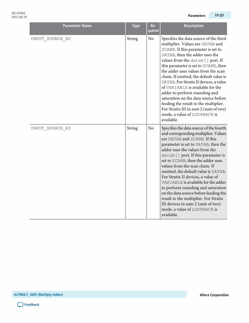
DescriptionRe-quired
TypeParameter Name
Specifies the data source of the thirdmultiplier. Values are DATAB andSCANB. If this parameter is set toDATAB, then the adder uses thevalues from the datab[] port. Ifthis parameter is set to SCANB, thenthe adder uses values from the scanchain. If omitted, the default value isDATAB. For Stratix II devices, a valueof VARIABLE is available for theadder to perform rounding andsaturation on the data source beforefeeding the result to the multiplier.For Stratix III in sum 2 (sum of two)mode, a value of LOOPBACK isavailable.
NoStringINPUT_SOURCE_B2
Specifies the data source of the fourthand correspondingmultiplier.Valuesare DATAB and SCANB. If thisparameter is set to DATAB, then theadder uses the values from thedatab[] port. If this parameter isset to SCANB, then the adder usesvalues from the scan chain. Ifomitted, the default value is DATAB.For Stratix II devices, a value ofVARIABLE is available for the adderto perform rounding and saturationon the data source before feeding theresult to the multiplier. For StratixIII devices in sum 2 (sum of two)mode, a value of LOOPBACK isavailable.
NoStringINPUT_SOURCE_B3
Altera CorporationALTMULT_ADD (Multiply-Adder)
Feedback
11-21ParametersUG-010632013.06.10

DescriptionRe-quired
TypeParameter Name
Specifies the numericalrepresentation of themultiplier inputA. Values are UNSIGNED, SIGNEDand VARIABLE. When thisparameter is set to SIGNED, theadder interprets the multiplier inputA as a signed two's complementnumber. When this parameter is setto UNSIGNED, the adder interpretsthemultiplier inputA as an unsignednumber. If omitted, the default valueis UNSIGNED. Use the VARIABLEsetting to access the SIGNED_REGISTER_A and the SIGNED_PIPELINE_REGISTER_Aparameter options for the signainput port.
NoStringREPRESENTATION_A
Specifies the numericalrepresentation of themultiplier inputB port. Values are UNSIGNED,SIGNED, and VARIABLE. Whenthis parameter is set to UNSIGNED,the adder interprets the multiplierinput B as an unsigned number.When this parameter is set toSIGNED, the adder interprets themultiplier input B as a signed two'scomplement number. If omitted, thedefault value is UNSIGNED. Use theVARIABLE setting to access theSIGNED_REGISTER_B and theSIGNED_PIPELINE_REGISTER_B parameter options for the signbinput port.
NoStringREPRESENTATIONS_B
Parameter [A,B]. Specifies theclock signal for the first register onthe corresponding sign[] port.Values are UNREGISTERED,CLOCK0, CLOCK1, CLOCK2, andCLOCK3. If the correspondingsign[] port value is UNUSED, thisparameter is ignored. If omitted, thedefault value is CLOCK0.
NoStringSIGNED_REGISTER_[]
ALTMULT_ADD (Multiply-Adder)Altera Corporation
Feedback
UG-01063Parameters11-22 2013.06.10

DescriptionRe-quired
TypeParameter Name
Parameter [A,B]. Specifies theclock signal for the second registeron the correspondingsign[] port.Values are UNREGISTERED,CLOCK0, CLOCK1, CLOCK2, andCLOCK3. If the correspondingsign[] port value is UNUSED, thisparameter is ignored. If omitted, thedefault value is CLOCK0.
NoStringSIGNED_PIPELINE_REGISTER_[]
Parameter [A,B]. Specifies theasynchronous clear signal for the firstregister on the correspondingsign[] port. Values are NONE,ACLR0, ACLR1, ACLR2, andACLR3. If omitted andcorresponding SIGNED_REGISTER_[] is used, the defaultvalue is ACLR3.
NoStringSIGNED_ACLR_[]
Parameter [A,B]. Specifies theasynchronous clear signal for thesecond register on the correspondingsign[] port. Values areNONE,ACLR0, ACLR1, ACLR2, andACLR3. If omitted and thecorresponding SIGNED_PIPELINE_REGISTER_[] isused, the default value is ACLR3.
NoStringSIGNED_PIPELINE_ACLR_[]
Parameter [0..3]. Specifies theclock source of the register thatfollows the correspondingmultiplier.Values are UNREGISTERED,CLOCK0, CLOCK1, CLOCK2, andCLOCK3. If omitted, the defaultvalue is CLOCK0.
NoStringMULTIPLIER_REGISTER[]
Parameter [0..3]. Specifies theasynchronous clear signal of theregister that follows thecorrespondingmultiplier. Values areNONE,ACLR0, ACLR1, ACLR2, andACLR3. If omitted andcorresponding MULTIPLIER_REGISTER[] is used, the defaultvalue is ACLR3.
NoStringMULTIPLIER_ACLR[]
Altera CorporationALTMULT_ADD (Multiply-Adder)
Feedback
11-23ParametersUG-010632013.06.10

DescriptionRe-quired
TypeParameter Name
Specifies whether the secondmultiplier adds or subtracts its valuefrom the sum. Values are ADD andSUB. If the addnsub1 port is used,this parameter is ignored. If omitted,the default value is ADD.
NoStringMUTIPLIER1_DIRECTION
Specifies whether the fourth and allsubsequent odd-numberedmultipliers add or subtract theirresults from the total. Values areADDand SUB. If the addnsub3 port isused, this parameter is ignored. Ifomitted, the default value is ADD.
NoStringMUTIPLIER3_DIRECTION
Specifies whether to use theaccumulator and whether theaccumulator adds or subtracts itsvalue from the sum. Values are ADDandSUB. If omitted, the default valueis ADD.
NoStringACCUM_DIRECTION
Specifies the clock signal for thesecond adder register. Values areUNREGISTERED, CLOCK0,CLOCK1,CLOCK2, andCLOCK3. Ifomitted, the default value isCLOCK0.
NoStringOUTPUT_REGISTER
Specifies the asynchronous clearsignal for the second adder register.Values are NONE, ACLR0, ACLR1,ACLR2, and ACLR3. If omitted, thedefault value is ACLR3.
NoStringOUTPUT_ACLR
Parameter [A,B]. Specifies thecorresponding sign[] input portusage. Values are PORT_USED,PORT_UNUSED, and PORT_CONNECTIVITY. If omitted, thedefault value is PORT_CONNECTIVITY.
NoStringPORT_SIGN[]
ALTMULT_ADD (Multiply-Adder)Altera Corporation
Feedback
UG-01063Parameters11-24 2013.06.10
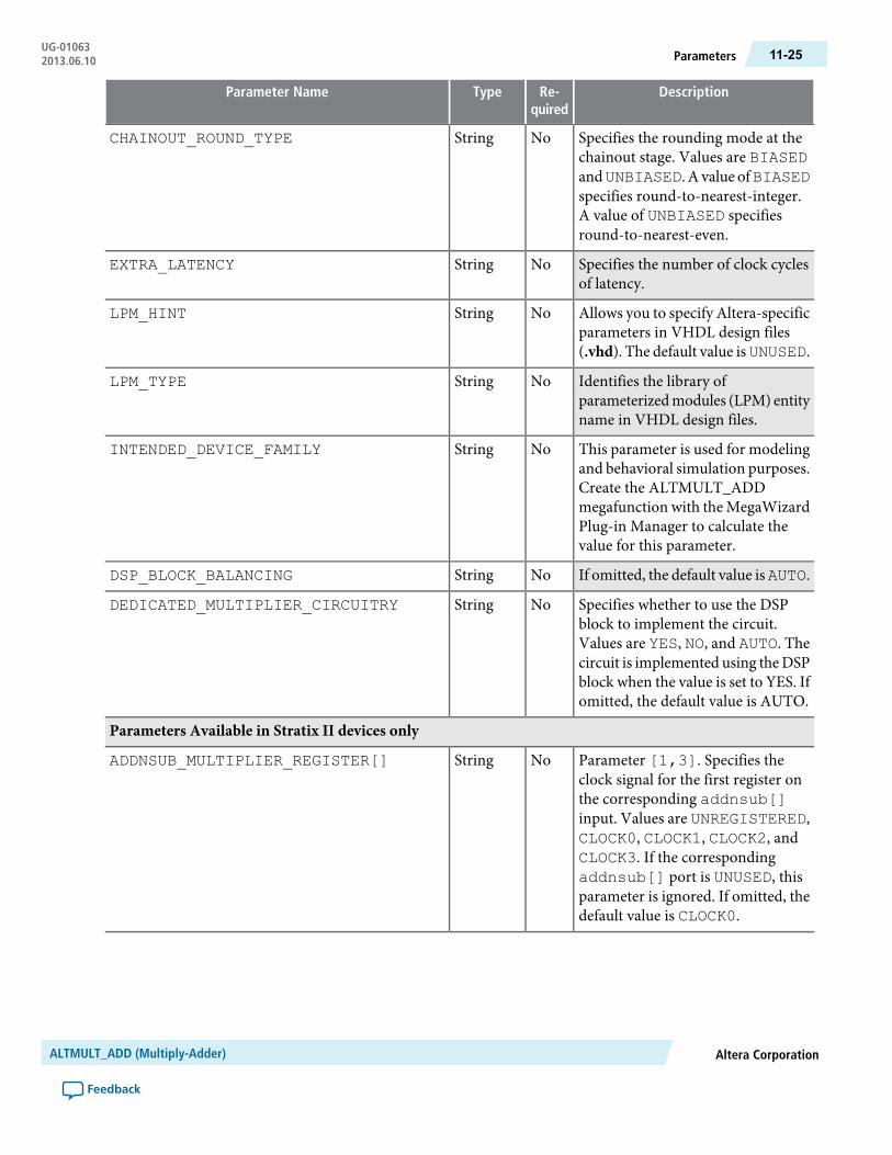
DescriptionRe-quired
TypeParameter Name
Specifies the rounding mode at thechainout stage. Values are BIASEDandUNBIASED. A value ofBIASEDspecifies round-to-nearest-integer.A value of UNBIASED specifiesround-to-nearest-even.
NoStringCHAINOUT_ROUND_TYPE
Specifies the number of clock cyclesof latency.
NoStringEXTRA_LATENCY
Allows you to specify Altera-specificparameters in VHDL design files(.vhd). The default value isUNUSED.
NoStringLPM_HINT
Identifies the library ofparameterizedmodules (LPM) entityname in VHDL design files.
NoStringLPM_TYPE
This parameter is used for modelingand behavioral simulation purposes.Create the ALTMULT_ADDmegafunction with the MegaWizardPlug-in Manager to calculate thevalue for this parameter.
NoStringINTENDED_DEVICE_FAMILY
If omitted, the default value isAUTO.NoStringDSP_BLOCK_BALANCING
Specifies whether to use the DSPblock to implement the circuit.Values are YES, NO, and AUTO. Thecircuit is implemented using theDSPblock when the value is set to YES. Ifomitted, the default value is AUTO.
NoStringDEDICATED_MULTIPLIER_CIRCUITRY
Parameters Available in Stratix II devices only
Parameter [1,3]. Specifies theclock signal for the first register onthe corresponding addnsub[]input. Values are UNREGISTERED,CLOCK0, CLOCK1, CLOCK2, andCLOCK3. If the correspondingaddnsub[] port is UNUSED, thisparameter is ignored. If omitted, thedefault value is CLOCK0.
NoStringADDNSUB_MULTIPLIER_REGISTER[]
Altera CorporationALTMULT_ADD (Multiply-Adder)
Feedback
11-25ParametersUG-010632013.06.10

DescriptionRe-quired
TypeParameter Name
Parameter [1,3]. Specifies theasynchronous clear signal for the firstregister on the correspondingaddnsub[] input. Values areACLR0, ACLR1, ACLR2, andACLR3. If the correspondingaddnsub[] port value is UNUSED,this parameter is ignored. If omittedand corresponding ADDNSUB_MULTIPLIER_REGISTER[] isused, the default value is ACLR3.
NoStringADDSUB_MULTIPLIER_ACLR[]
Parameter [1,3]. Specifies theclock signal for the second registeron the corresponding addnsub[]input. Values are UNREGISTERED,CLOCK0, CLOCK1, CLOCK2, andCLOCK3. If the correspondingaddnsub[] port is UNUSED, thisparameter is ignored. If omitted, thedefault value is CLOCK0.
NoStringADDNSUB_MULTIPLIER_PIPELINE_REGISTER[]
Parameter [1,3]. Specifies theasynchronous clear signal for thesecond register on the correspondingaddnsub[] input. Values areACLR0, ACLR1, ACLR2, andACLR3. If omitted andcorresponding ADDNSUB_MULTIPLIER_PIPELINE_REGISTER[] is used, the defaultvalue is ACLR3.
NoStringADDNSUB_MULTIPLIER_PIPELINE_ACLR[]
Parameter [1,3]. Specifies theusage of the correspondingaddnsub[] input port. Values arePORT_USED, PORT_UNUSED, andPORT_CONNECTIVITY. A value ofPORT_CONNECTIVITY specifiesthe port usage by checking portconnectivity. If omitted, the defaultvalue is PORT_CONNECTIVITY.
NoStringPORT_ADDNSUB[]
ALTMULT_ADD (Multiply-Adder)Altera Corporation
Feedback
UG-01063Parameters11-26 2013.06.10

DescriptionRe-quired
TypeParameter Name
Parameter [01,23]. Specifiesrounding for the first and secondmultiplier [01], or the third andfourth multiplier [23]. Values areNO, YES, and VARIABLE. Ifomitted, the default value is NO.
NoStringMULTIPLIER[]_ROUNDING
Parameter [01,23]. Specifiessaturation for the first and secondmultiplier [01], or the third andfourth multiplier [23]. Values areNO, YES, and VARIABLE. Ifomitted, the default value is NO.
NoStringMULTIPLIER[]_SATURATION
Parameter [1,3]. Specifies adderrounding for the firstmultiplier[1],or the third multiplier [3]. Valuesare NO, YES, and VARIABLE. Ifomitted, the default value is NO.
NoStringADDER[]_ROUNDING
Parameter [0..3]. Specifieswhether to use the correspondingmult[]_is_saturated outputport. Values are NO and YES. Ifomitted, the default value is NO.
NoStringPORT_MULT[]_IS_SATURATED
Specifies the fractional roundingwidth. The value is determined bycounting the bits from the MSB(before saturation) to the LSB (afterrounding). Values are calculatedaccording to the following modes:WIDTH_A,WIDTH_B, andWIDTH_RESULT. Valuemust be an unsignedinteger, and must be less thanWIDTH_RESULT. If a positivenumber is unavailable, no saturationis allowed in your input/outputwidthand mode setting. If omitted, thedefault value is 17, which iscompatible with Stratix II devicesettings.
NoIntegerWIDTH_MSB
Altera CorporationALTMULT_ADD (Multiply-Adder)
Feedback
11-27ParametersUG-010632013.06.10

DescriptionRe-quired
TypeParameter Name
Parameter [1,3]. Specifies theasynchronous clear source for thefirst register on the correspondingaddnsub[]_round input port.Values are ACLR0, ACLR1, ACLR2,and ACLR3. If omitted andcorresponding ADDNSUB[]_ROUND_REGISTER is used, thedefault value is ACLR3.
NoStringADDNSUB[]_ROUND_ACLR
Parameter [1,3]. Specifies theasynchronous clear source for thesecond register on the correspondingaddnsub[]_round input port.Values are ACLR0, ACLR1, ACLR2,and ACLR3. If omitted andcorresponding ADDNSUB_[]_ROUND_PIPELINE_REGISTER isused, the default value is ACLR3.
NoStringADDNSUB[]_ROUND_PIPELINE_ACLR
Parameter [1, 3]. Specifies theclock source for the second registeron the correspondingaddnsub[]_round input port. Values areUNREGISTERED, CLOCK0,CLOCK1,CLOCK2, andCLOCK3. Ifomitted, the default value isCLOCK0.
NoStringADDNSUB[]_ROUND_PIPELINE_REGISTER
Parameter [1,3]. Specifies theclock source for the first register onthe corresponding addnsub[]_round input port. Values areUNREGISTERED, CLOCK0,CLOCK1,CLOCK2, andCLOCK3. Ifomitted, the default value isCLOCK0.
NoStringADDNSUB[]_ROUND_REGISTER
Parameter [01,23]. Specifies theasynchronous clear source for thesecond register on the correspondingmult[]_round input port. Valuesare ACLR0, ACLR1, ACLR2, andACLR3. If omitted andcorresponding MULT[]_ROUND_REGISTER is used, the default valueis ACLR3.
NoStringMULT[]_ROUND_ACLR
ALTMULT_ADD (Multiply-Adder)Altera Corporation
Feedback
UG-01063Parameters11-28 2013.06.10

DescriptionRe-quired
TypeParameter Name
Parameter [01,23]. Specifies theclock source for the register on thecorresponding mult[]_roundinput port. Values areUNREGISTERED, CLOCK0,CLOCK1, CLOCK2, and CLOCK3. Ifomitted, the default value isCLOCK0.
NoStringMULT[]_ROUND_REGISTER
Parameter [01,23]. Specifies theasynchronous clear source for theregister on the correspondingmult[]_saturation input port.Values are ACLR0, ACLR1, ACLR2,and ACLR3. If omitted andcorresponding MULT[]_SATURATION_REGISTER is used,the default value is ACLR3.
NoStringMULT[]_SATURATION_ACLR
Parameter [01,23]. Specifies theclock source for the register on thecorresponding mult[]_saturation input port.Values areUNREGISTERED, CLOCK0,CLOCK1, CLOCK2, and CLOCK3. Ifomitted, the default value isCLOCK0.
NoStringMULT[]_SATURATION_REGISTER
Parameters Available in Stratix II, Stratix III, and Stratix IV devices only
Specifies the saturationmode.ValuesareSYMMETRICandASYMMETRIC.A value ofSYMMETRIC specifies theabsolute value of the maximumnegative number equal to themaximum positive number. A valueof ASYMMETRIC specifies themaximum negative number is largerthan themaximumpositive number.If omitted, the default value isASYMMETRIC.
NoStringOUTPUT_SATURATE_TYPE
Altera CorporationALTMULT_ADD (Multiply-Adder)
Feedback
11-29ParametersUG-010632013.06.10
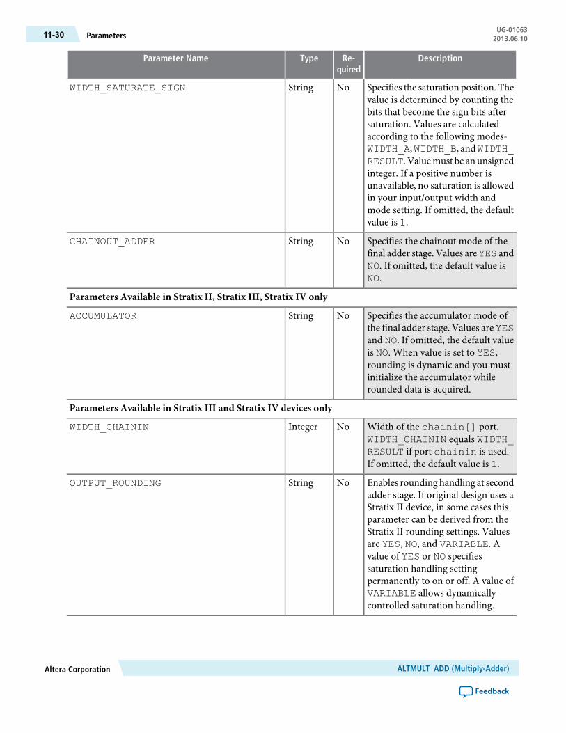
DescriptionRe-quired
TypeParameter Name
Specifies the saturation position. Thevalue is determined by counting thebits that become the sign bits aftersaturation. Values are calculatedaccording to the following modes-WIDTH_A,WIDTH_B, andWIDTH_RESULT. Valuemust be an unsignedinteger. If a positive number isunavailable, no saturation is allowedin your input/output width andmode setting. If omitted, the defaultvalue is 1.
NoStringWIDTH_SATURATE_SIGN
Specifies the chainout mode of thefinal adder stage. Values areYES andNO. If omitted, the default value isNO.
NoStringCHAINOUT_ADDER
Parameters Available in Stratix II, Stratix III, Stratix IV only
Specifies the accumulator mode ofthe final adder stage. Values areYESand NO. If omitted, the default valueis NO. When value is set to YES,rounding is dynamic and you mustinitialize the accumulator whilerounded data is acquired.
NoStringACCUMULATOR
Parameters Available in Stratix III and Stratix IV devices only
Width of the chainin[] port.WIDTH_CHAININ equals WIDTH_RESULT if port chainin is used.If omitted, the default value is 1.
NoIntegerWIDTH_CHAININ
Enables rounding handling at secondadder stage. If original design uses aStratix II device, in some cases thisparameter can be derived from theStratix II rounding settings. Valuesare YES, NO, and VARIABLE. Avalue of YES or NO specifiessaturation handling settingpermanently to on or off. A value ofVARIABLE allows dynamicallycontrolled saturation handling.
NoStringOUTPUT_ROUNDING
ALTMULT_ADD (Multiply-Adder)Altera Corporation
Feedback
UG-01063Parameters11-30 2013.06.10

DescriptionRe-quired
TypeParameter Name
Specifies the roundingmode. Valuesare NEAREST_EVEN andNEAREST_INTEGER. A value ofNEAREST_EVEN specifiesround-to-nearest-even. A value ofNEAREST_INTEGER specifiesround-to-nearest-integer. If omitted,the default value is NEAREST_INTEGER.
NoStringOUTPUT_ROUND_TYPE
Specifies the clock source for the firstregister on the output_roundinput. Values are UNREGISTERED,CLOCK0, CLOCK1, CLOCK2, andCLOCK3. If omitted, the defaultvalue is CLOCK0.
NoStringOUTPUT_ROUND_REGISTER
Specifies the asynchronous clearsource for the first register on theoutput_round input. Values areACLR0, ACLR1, ACLR2, andACLR3. If omitted and OUTPUT_ROUND_REGISTER is used, thedefault value is ACLR3.
NoStringOUTPUT_ROUND_ACLR
Specifies the clock source for thesecond register on the output_round input. Values areUNREGISTERED, CLOCK0,CLOCK1, CLOCK2, and CLOCK3. Ifomitted, the default value isCLOCK0.
NoStringOUTPUT_ROUND_PIPELINE_REGISTER
Specifies the asynchronous clearsource for the second register on theoutput_round input. Values areACLR0, ACLR1, ACLR2, andACLR3. If omitted and OUTPUT_ROUND_PIPELINE_ REGISTERis used, the default value is ACLR3.
NoStringOUTPUT_ROUND_PIPELINE_ACLR
Altera CorporationALTMULT_ADD (Multiply-Adder)
Feedback
11-31ParametersUG-010632013.06.10

DescriptionRe-quired
TypeParameter Name
Enables saturation handling atsecond adder stage. If original designuses a Stratix II device, in some casesthis parameter can be derived fromthe Stratix II rounding settings.Values areYES,NO, andVARIABLE.A value of YES or NO specifiessaturation handling settingpermanently to on or off. A value ofVARIABLE allows dynamicallycontrolled saturation handling. Ifomitted, the default value is NO.
NoStringOUTPUT_SATURATION
Specifies the clock source for the firstregister on theoutput_saturateinput. Values are UNREGISTERED,CLOCK0, CLOCK1, CLOCK2, andCLOCK3. If omitted, the defaultvalue is UNREGISTERED.
NoStringOUTPUT_SATURATE_REGISTER
Specifies the asynchronous clearsource for the first register on theoutput_saturate input.Valuesare ACLR0, ACLR1, ACLR2, andACLR3. If omitted and OUTPUT_SATURATE_REGISTER is used,the default value is ACLR3.
NoStringOUTPUT_SATURATE_ACLR
Specifies the clock source for thesecond register on the output_saturate input. Values areUNREGISTERED, CLOCK0,CLOCK1, CLOCK2, and CLOCK3. Ifomitted, the default value isCLOCK0.
NoStringOUTPUT_SATURATE_PIPELINE_REGISTER
Specifies the asynchronous clearsource for the second register on theoutput_saturate input.Valuesare ACLR0, ACLR1, ACLR2, andACLR3. If omitted and OUTPUT_SATURATE_ PIPELINE_REGISTER is used, the default valueis ACLR3.
NoStringOUTPUT_SATURATE_PIPELINE_ACLR
ALTMULT_ADD (Multiply-Adder)Altera Corporation
Feedback
UG-01063Parameters11-32 2013.06.10
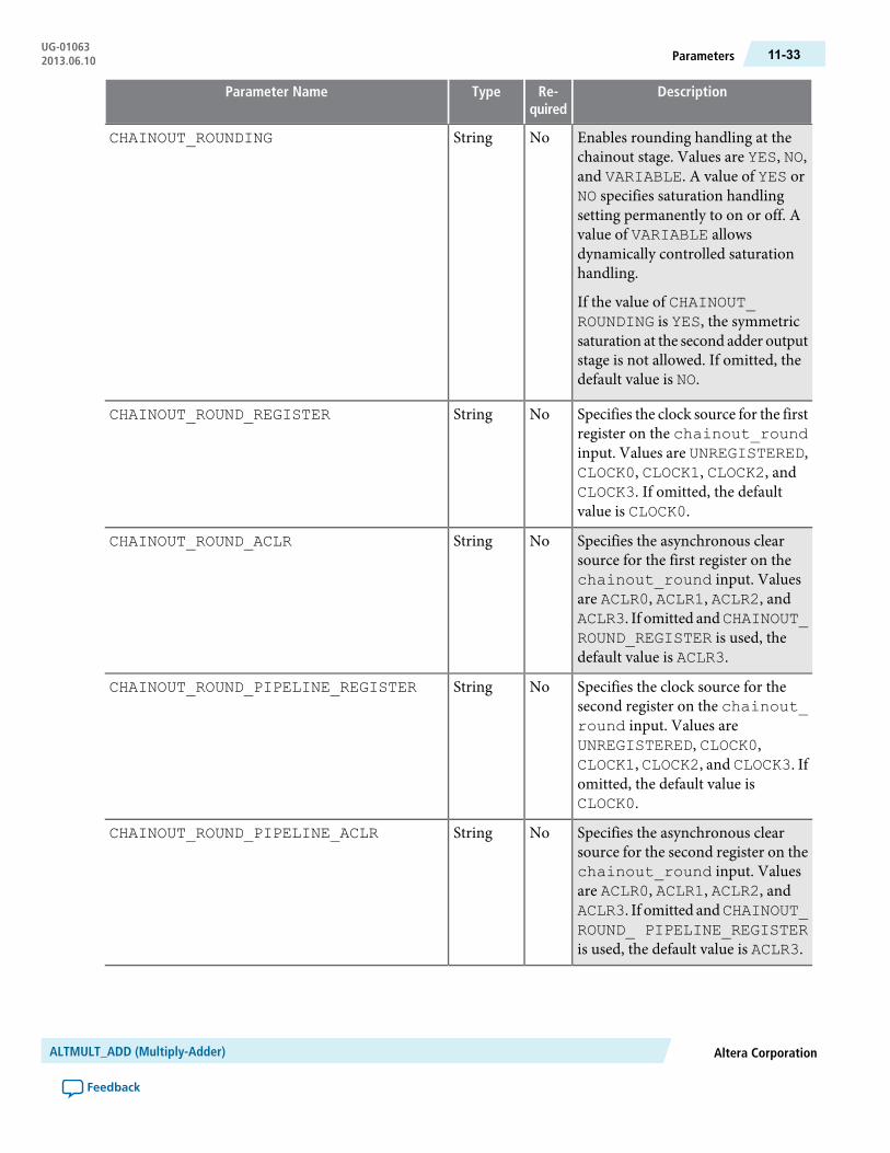
DescriptionRe-quired
TypeParameter Name
Enables rounding handling at thechainout stage. Values are YES, NO,and VARIABLE. A value of YES orNO specifies saturation handlingsetting permanently to on or off. Avalue of VARIABLE allowsdynamically controlled saturationhandling.
If the value of CHAINOUT_ROUNDING is YES, the symmetricsaturation at the second adder outputstage is not allowed. If omitted, thedefault value is NO.
NoStringCHAINOUT_ROUNDING
Specifies the clock source for the firstregister on the chainout_roundinput. Values are UNREGISTERED,CLOCK0, CLOCK1, CLOCK2, andCLOCK3. If omitted, the defaultvalue is CLOCK0.
NoStringCHAINOUT_ROUND_REGISTER
Specifies the asynchronous clearsource for the first register on thechainout_round input. Valuesare ACLR0, ACLR1, ACLR2, andACLR3. If omitted andCHAINOUT_ROUND_REGISTER is used, thedefault value is ACLR3.
NoStringCHAINOUT_ROUND_ACLR
Specifies the clock source for thesecond register on the chainout_round input. Values areUNREGISTERED, CLOCK0,CLOCK1, CLOCK2, and CLOCK3. Ifomitted, the default value isCLOCK0.
NoStringCHAINOUT_ROUND_PIPELINE_REGISTER
Specifies the asynchronous clearsource for the second register on thechainout_round input. Valuesare ACLR0, ACLR1, ACLR2, andACLR3. If omitted andCHAINOUT_ROUND_ PIPELINE_REGISTERis used, the default value is ACLR3.
NoStringCHAINOUT_ROUND_PIPELINE_ACLR
Altera CorporationALTMULT_ADD (Multiply-Adder)
Feedback
11-33ParametersUG-010632013.06.10
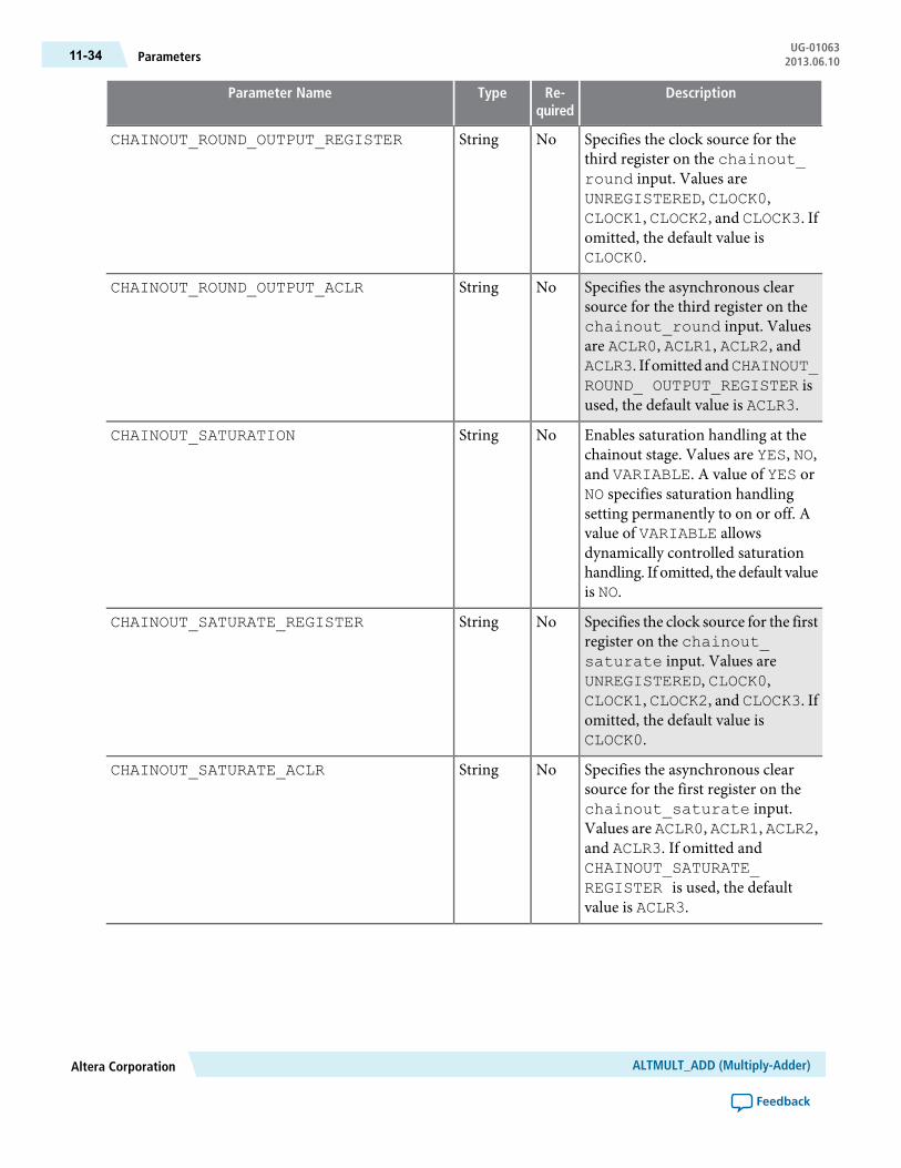
DescriptionRe-quired
TypeParameter Name
Specifies the clock source for thethird register on the chainout_round input. Values areUNREGISTERED, CLOCK0,CLOCK1, CLOCK2, and CLOCK3. Ifomitted, the default value isCLOCK0.
NoStringCHAINOUT_ROUND_OUTPUT_REGISTER
Specifies the asynchronous clearsource for the third register on thechainout_round input. Valuesare ACLR0, ACLR1, ACLR2, andACLR3. If omitted andCHAINOUT_ROUND_ OUTPUT_REGISTER isused, the default value is ACLR3.
NoStringCHAINOUT_ROUND_OUTPUT_ACLR
Enables saturation handling at thechainout stage. Values are YES, NO,and VARIABLE. A value of YES orNO specifies saturation handlingsetting permanently to on or off. Avalue of VARIABLE allowsdynamically controlled saturationhandling. If omitted, the default valueis NO.
NoStringCHAINOUT_SATURATION
Specifies the clock source for the firstregister on the chainout_saturate input. Values areUNREGISTERED, CLOCK0,CLOCK1, CLOCK2, and CLOCK3. Ifomitted, the default value isCLOCK0.
NoStringCHAINOUT_SATURATE_REGISTER
Specifies the asynchronous clearsource for the first register on thechainout_saturate input.Values are ACLR0, ACLR1, ACLR2,and ACLR3. If omitted andCHAINOUT_SATURATE_REGISTER is used, the defaultvalue is ACLR3.
NoStringCHAINOUT_SATURATE_ACLR
ALTMULT_ADD (Multiply-Adder)Altera Corporation
Feedback
UG-01063Parameters11-34 2013.06.10

DescriptionRe-quired
TypeParameter Name
Specifies the clock source for thesecond register on the chainout_saturate input. Values areUNREGISTERED, CLOCK0,CLOCK1, CLOCK2, and CLOCK3. Ifomitted, the default value isCLOCK0.
NoStringCHAINOUT_SATURATE_PIPELINE_REGISTER
Specifies the clock source for thethird register on the chainout_saturate input. Values areUNREGISTERED, CLOCK0,CLOCK1, CLOCK2, and CLOCK3. Ifomitted, the default value isCLOCK0.
NoStringCHAINOUT_SATURATE_OUTPUT_REGISTER
Specifies the asynchronous clearsource for the third register on thechainout_saturate input.Values are ACLR0, ACLR1, ACLR2,and ACLR3. If omitted andCHAINOUT_SATURATE_OUTPUT_REGISTER is used, thedefault value is ACLR3.
NoStringCHAINOUT_SATURATE_OUTPUT_ACLR
Specifies the clock source for the firstregister on the zero_chainoutinput. Values are UNREGISTERED,CLOCK0, CLOCK1, CLOCK2, andCLOCK3. If omitted, the defaultvalue is CLOCK0.
NoStringZERO_CHAINOUT_OUTPUT_REGISTER
Specifies the asynchronous clearsource for the first register on thezero_chainout input.Values areACLR0, ACLR1, ACLR2, andACLR3. If omitted and ZERO_CHAINOUT_OUTPUT_ REGISTERis used, the default value is ACLR3.
NoStringZERO_CHAINOUT_OUTPUT_ACLR
Specifies the clock source for the firstregister on the zero_loopbackinput. Values are UNREGISTERED,CLOCK0, CLOCK1, CLOCK2, andCLOCK3. If omitted, the defaultvalue is CLOCK0.
NoStringZERO_LOOPBACK_REGISTER
Altera CorporationALTMULT_ADD (Multiply-Adder)
Feedback
11-35ParametersUG-010632013.06.10

DescriptionRe-quired
TypeParameter Name
Specifies the asynchronous clearsource for the first register on thezero_loopback input.Values areACLR0, ACLR1, ACLR2, andACLR3. If omitted and ZERO_LOOPBACK_ PIPELINE_REGISTER is used, the default valueis ACLR3.
NoStringZERO_LOOPBACK_ACLR
Specifies the clock source for thesecond register on the zero_loopback input. Values areUNREGISTERED, CLOCK0,CLOCK1, CLOCK2, and CLOCK3. Ifomitted, the default value isCLOCK0.
NoStringZERO_LOOPBACK_PIPELINE_REGISTER
Specifies the asynchronous clearsource for the second register on thezero_loopback input.Values areACLR0, ACLR1, ACLR2, andACLR3. If omitted and ZERO_LOOPBACK_ PIPELINE_REGISTER is used, the default valueis ACLR3.
NoStringZERO_LOOPBACK_PIPELINE_ACLR
Specifies the clock source for thethird register on the zero_loopback input. Values areUNREGISTERED, CLOCK0,CLOCK1, CLOCK2, and CLOCK3. Ifomitted, the default value isCLOCK0.
NoStringZERO_LOOPBACK_OUTPUT_REGISTER
Specifies the asynchronous clearsource for the third register on thezero_loopback input.Values areACLR0, ACLR1, ACLR2, andACLR3. If omitted and ZERO_LOOPBACK_OUTPUT_ REGISTERis used, the default value is ACLR3.
NoStringZERO_LOOPBACK_OUTPUT_ACLR
Specifies the clock source for the firstregister on the accum_sloadinput. Values are UNREGISTERED,CLOCK0, CLOCK1, CLOCK2, andCLOCK3. If omitted, the defaultvalue is CLOCK0.
NoStringACCUM_SLOAD_REGISTER
ALTMULT_ADD (Multiply-Adder)Altera Corporation
Feedback
UG-01063Parameters11-36 2013.06.10
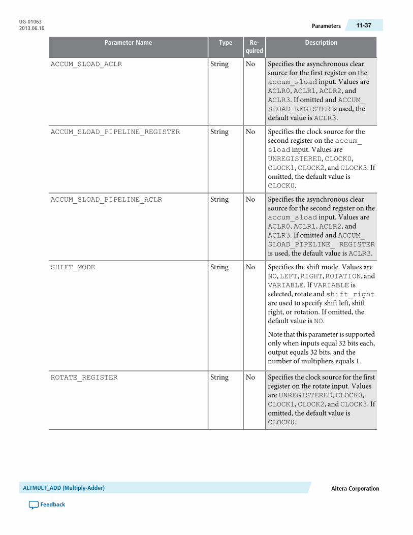
DescriptionRe-quired
TypeParameter Name
Specifies the asynchronous clearsource for the first register on theaccum_sload input. Values areACLR0, ACLR1, ACLR2, andACLR3. If omitted and ACCUM_SLOAD_REGISTER is used, thedefault value is ACLR3.
NoStringACCUM_SLOAD_ACLR
Specifies the clock source for thesecond register on the accum_sload input. Values areUNREGISTERED, CLOCK0,CLOCK1, CLOCK2, and CLOCK3. Ifomitted, the default value isCLOCK0.
NoStringACCUM_SLOAD_PIPELINE_REGISTER
Specifies the asynchronous clearsource for the second register on theaccum_sload input. Values areACLR0, ACLR1, ACLR2, andACLR3. If omitted and ACCUM_SLOAD_PIPELINE_ REGISTERis used, the default value is ACLR3.
NoStringACCUM_SLOAD_PIPELINE_ACLR
Specifies the shift mode. Values areNO,LEFT,RIGHT,ROTATION, andVARIABLE. If VARIABLE isselected, rotate and shift_rightare used to specify shift left, shiftright, or rotation. If omitted, thedefault value is NO.
Note that this parameter is supportedonly when inputs equal 32 bits each,output equals 32 bits, and thenumber of multipliers equals 1.
NoStringSHIFT_MODE
Specifies the clock source for the firstregister on the rotate input. Valuesare UNREGISTERED, CLOCK0,CLOCK1, CLOCK2, and CLOCK3. Ifomitted, the default value isCLOCK0.
NoStringROTATE_REGISTER
Altera CorporationALTMULT_ADD (Multiply-Adder)
Feedback
11-37ParametersUG-010632013.06.10
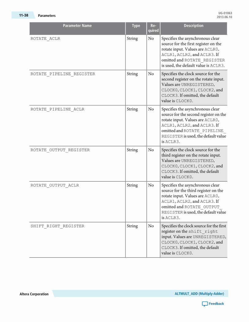
DescriptionRe-quired
TypeParameter Name
Specifies the asynchronous clearsource for the first register on therotate input. Values are ACLR0,ACLR1, ACLR2, and ACLR3. Ifomitted and ROTATE_REGISTERis used, the default value is ACLR3.
NoStringROTATE_ACLR
Specifies the clock source for thesecond register on the rotate input.Values are UNREGISTERED,CLOCK0, CLOCK1, CLOCK2, andCLOCK3. If omitted, the defaultvalue is CLOCK0.
NoStringROTATE_PIPELINE_REGISTER
Specifies the asynchronous clearsource for the second register on therotate input. Values are ACLR0,ACLR1, ACLR2, and ACLR3. Ifomitted andROTATE_PIPELINE_REGISTER is used, the default valueis ACLR3.
NoStringROTATE_PIPELINE_ACLR
Specifies the clock source for thethird register on the rotate input.Values are UNREGISTERED,CLOCK0, CLOCK1, CLOCK2, andCLOCK3. If omitted, the defaultvalue is CLOCK0.
NoStringROTATE_OUTPUT_REGISTER
Specifies the asynchronous clearsource for the third register on therotate input. Values are ACLR0,ACLR1, ACLR2, and ACLR3. Ifomitted and ROTATE_OUTPUT_REGISTER is used, the default valueis ACLR3.
NoStringROTATE_OUTPUT_ACLR
Specifies the clock source for the firstregister on the shift_rightinput. Values are UNREGISTERED,CLOCK0, CLOCK1, CLOCK2, andCLOCK3. If omitted, the defaultvalue is CLOCK0.
NoStringSHIFT_RIGHT_REGISTER
ALTMULT_ADD (Multiply-Adder)Altera Corporation
Feedback
UG-01063Parameters11-38 2013.06.10

DescriptionRe-quired
TypeParameter Name
Specifies the asynchronous clearsource for the first register on theshift_right input. Values areNONE,ACLR0,ACLR1,ACLR2, andACLR3. If omitted and SHIFT_RIGHT_REGISTER is used, thedefault value is ACLR3.
NoStringSHIFT_RIGHT_ACLR
Specifies the clock source for thesecond register on the shift_rightinput. Values are UNREGISTERED,CLOCK0, CLOCK1, CLOCK2, andCLOCK3. If omitted, the defaultvalue is CLOCK0.
NoStringSHIFT_RIGHT_PIPELINE_REGISTER
Specifies the asynchronous clearsource for the second register on theshift_right input. Values areACLR0, ACLR1, ACLR2, andACLR3. If omitted and SHIFT_RIGHT_PIPELINE_ REGISTERis used, the default value is ACLR3.
NoStringSHIFT_RIGHT_PIPELINE_ACLR
Specifies the clock source for thethird register on theshift_rightinput. Values are UNREGISTERED,CLOCK0, CLOCK1, CLOCK2, andCLOCK3. If omitted, the defaultvalue is CLOCK0.
NoStringSHIFT_RIGHT_OUTPUT_REGISTER
Specifies the asynchronous clearsource for the third register on theshift_right input. Values areACLR0, ACLR1, ACLR2, andACLR3. If omitted and SHIFT_RIGHT_OUTPUT_REGISTER isused, the default value is ACLR3.
NoStringSHIFT_RIGHT_OUTPUT_ACLR
Specifies port usage. Values arePORT_UNUSED and PORT_USED.When the value is set to PORT_USED, output pin overflow is added.If omitted, the default value isPORT_UNUSED.
NoStringPORT_OUTPUT_IS_OVERFLOW
Altera CorporationALTMULT_ADD (Multiply-Adder)
Feedback
11-39ParametersUG-010632013.06.10

DescriptionRe-quired
TypeParameter Name
Specifies port usage. Values arePORT_UNUSED and PORT_USED.When the value is set to PORT_USED, output pin chainout_sat_overflow is added. Ifomitted, the default value is PORT_UNUSED.
NoStringPORT_CHAINOUT_SAT_IS_OVERFLOW
Parameters Available in Stratix III and Stratix IV only
Specifies the clock source for thescanouta data bus registers.Values are UNREGISTERED,CLOCK0, CLOCK1, CLOCK2, andCLOCK3. If omitted, the defaultvalue is UNREGISTERED.
NoStringSCANOUTA_REGISTER
Specifies the asynchronous clearsource for the scanouta data busregisters. Values are NONE, ACLR0,ACLR1, ACLR2, and ACLR3. Ifomitted and SCANOUTA_REGISTER is used, the default valueis ACLR3.
NoStringSCANOUTA_ACLR
Specifies the clock source for thechainout mode result register. Thisis an additional stage after the secondadder. Values areUNREGISTERED,CLOCK0, CLOCK1, CLOCK2, andCLOCK3. If omitted, the defaultvalue is CLOCK0.
NoStringCHAINOUT_REGISTER
Specifies the asynchronous clear forthe chainout mode result register.This is an additional stage after thesecond adder. Values are NONE,ACLR0, ACLR1, ACLR2, andACLR3. If omitted andCHAINOUT_REGISTER is used, the default valueis ACLR3.
NoStringCHAINOUT_ACLR
Design Example: Implementing a Simple Finite Impulse Response (FIR) FilterThis design example uses the ALTMULT_ADD megafunction to implement a simple FIR filter as shown inthe following equation. This example uses the MegaWizard Plug-In Manager in the Quartus II software.
ALTMULT_ADD (Multiply-Adder)Altera Corporation
Feedback
UG-01063Design Example: Implementing a Simple Finite Impulse Response (FIR) Filter11-40 2013.06.10

n represents the number of taps, A(t) represents the sequence of input samples, and B(i) represents the filtercoefficients.
The number of taps (n) can be any value, but this example is of a simple FIR filter with n = 4, which is calleda 4-tap filter. To implement this filter, the coefficients of data B is loaded into the B registers in parallel anda shiftin register moves data A(0) to A(1) to A(2), and so on. With a 4-tap filter, at a given time (t), thesum of four products is computed. This function is implemented using the shift register chain option in theALTMULT_ADD megafunction.
With reference to the equation, input B represents the coefficients and data A represents the data that isshifted into. The A input (data) is shifted in with the main clock, named clock0. The B input (coefficients)is loaded at the rising edge of clock1 with the enable signal held high.
The following design files can be found in altmult_add_DesignExample.zip:
fir_fourtap.qar (archived Quartus II design files)
altmult_add_ex_msim (ModelSim-Altera files)
Understanding the Simulation ResultsThe following settings are observed in this example:
• The widths of the data inputs are all set to 16 bits• The width of the output port, result[], is set to 34 bits• The input registers are all operating on the same clock
The following figure shows the expected simulation results in the ModelSim-Altera software.
Figure 11-13: ALTMULT_ADD Simulation Results
Altera CorporationALTMULT_ADD (Multiply-Adder)
Feedback
11-41Understanding the Simulation ResultsUG-010632013.06.10

12ALTMULT_COMPLEX (Complex Multiplier)
2013.06.10UG-01063 Subscribe Feedback
The ALTMULT_COMPLEX megafunction implements the multiplication of two complex numbers andoffers the following two implementation modes:
• Canonical
You can use the canonical representation for the following:
• All supported Altera devices prior to Stratix III devices. The canonical representation is no longersupported from Stratix III onwards
• Input data widths of less than 18 bits
• Conventional
You can use the conventional representation for the following:
• All supported Altera devices• Input data widths of any size
With the conventional representation, you can use the ALTMULT_ADD megafunction to implement thecomplex multiplier by instantiating two multipliers.
The following figure shows the ports for the ALTMULT_COMPLEX megafunction.
Figure 12-1: ALTMULT_COMPLEX Ports
dataa_real
inst
ALTMULT_COMPLEX
datab_realdataa_imag
result_real
datab_imag
clockenaaclr
result_imag
ISO9001:2008Registered
© 2013 Altera Corporation. All rights reserved. ALTERA, ARRIA, CYCLONE, HARDCOPY, MAX, MEGACORE, NIOS, QUARTUS and STRATIXwords and logos are trademarks of Altera Corporation and registered in the U.S. Patent and Trademark Office and in other countries. All other wordsand logos identified as trademarks or service marks are the property of their respective holders as described at www.altera.com/common/legal.html.Altera warrants performance of its semiconductor products to current specifications in accordance with Altera's standard warranty, but reserves theright to make changes to any products and services at any time without notice. Altera assumes no responsibility or liability arising out of the applicationor use of any information, product, or service described herein except as expressly agreed to in writing by Altera. Altera customers are advised toobtain the latest version of device specifications before relying on any published information and before placing orders for products or services.
www.altera.com
101 Innovation Drive, San Jose, CA 95134
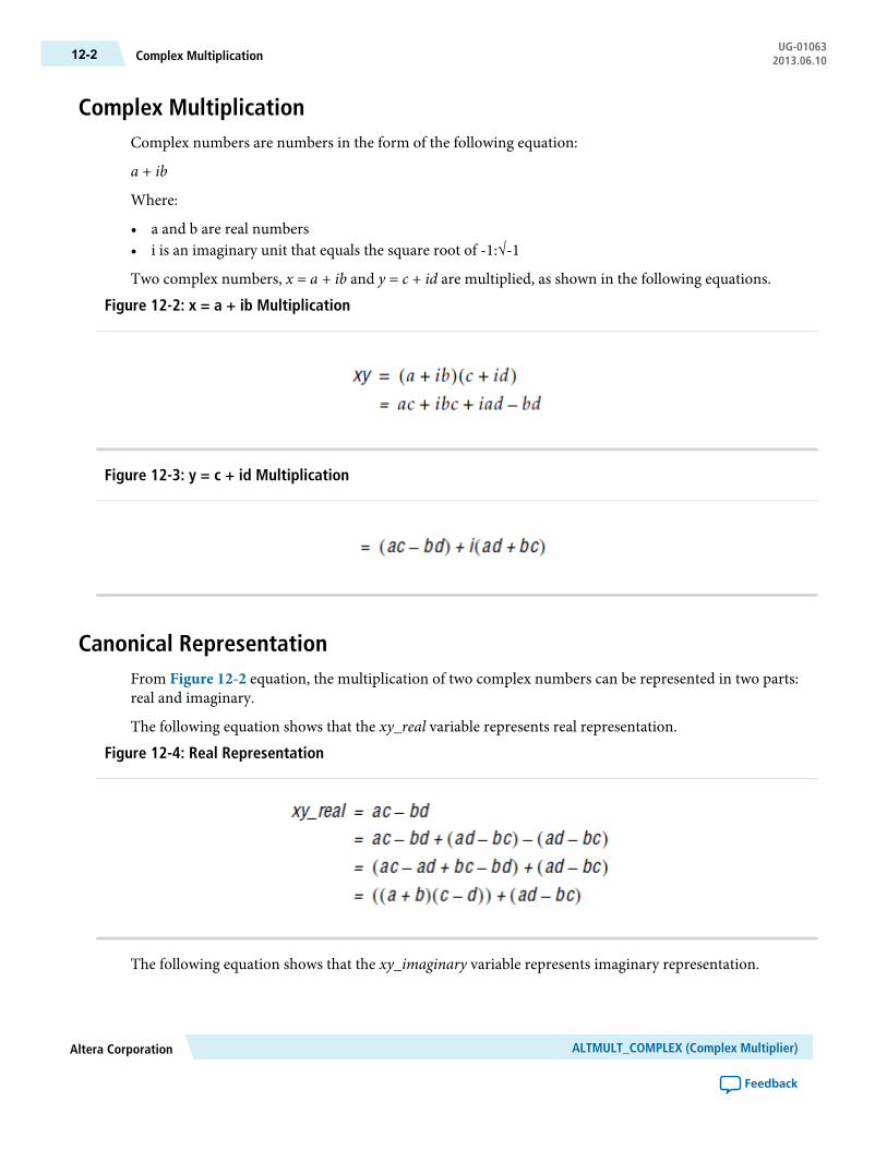
Complex MultiplicationComplex numbers are numbers in the form of the following equation:
a + ib
Where:
• a and b are real numbers• i is an imaginary unit that equals the square root of -1:√-1
Two complex numbers, x = a + ib and y = c + id are multiplied, as shown in the following equations.
Figure 12-2: x = a + ib Multiplication
Figure 12-3: y = c + id Multiplication
Canonical RepresentationFrom Figure 12-2 equation, the multiplication of two complex numbers can be represented in two parts:real and imaginary.
The following equation shows that the xy_real variable represents real representation.
Figure 12-4: Real Representation
The following equation shows that the xy_imaginary variable represents imaginary representation.
ALTMULT_COMPLEX (Complex Multiplier)Altera Corporation
Feedback
UG-01063Complex Multiplication12-2 2013.06.10

Figure 12-5: Imaginary Representation
Both equations derived from Figure 12-3 equation.
The canonical representation is available for all supported Altera devices prior to Stratix III devices.Note:
Conventional RepresentationThe multiplication of two complex numbers can be represented in two parts, real and imaginary. The xy_realvariable in the following equation represents the real part:
Figure 12-6: xy_real Variable
The xy_imaginary variable in the following equation represents the imaginary part.
Figure 12-7: xy_imaginary Variable
xy_imaginary = ad + bc
FeaturesThe ALTMULT_COMPLEX megafunction offers the following features:
• Generates a multiplier to perform multiplication operations of two complex numbers• Supports data width of 1–256 bits• Supports signed and unsigned data representation format• Supports canonical and conventional implementation modes• Supports pipelining with configurable output latency• Supports optional asynchronous clear and clock enable input ports• Provides an option to dynamically switch between 36 × 36 normal mode and 18 × 18 complex mode (for
Stratix V devices only)
Altera CorporationALTMULT_COMPLEX (Complex Multiplier)
Feedback
12-3Conventional RepresentationUG-010632013.06.10

Resource Utilization and PerformanceThe following table provides resource utilization andperformance information for theALTMULT_COMPLEXmegafunction.
Table 12-1: ALTMULT_COMPLEX Resource Utilization and Performance
fMAX (MHz) 918-bit DSP
Logic Usage
Outputlatency
Input datawidth
Device fam-ily
Adaptive Lo-gic Module
(ALM)
DedicatedLogic Re-
gister (DLR)
AdaptiveLook-Up
Table (ALUT)
529400008
Stratix III
5314000016
2911637073032
2921637073064
4924101019148
50241010191416
26516478911432
26816478911464
487400008
Stratix IV
4874000016
2931637073032
2931637073064
4894101019148
49341010201416
29216478911432
29116478911464
Verilog HDL PrototypeThe following Verilog HDL prototype is located in the Verilog Design File (.v) altera_mf.v in the <QuartusII installation directory>\eda\synthesis directory.
module altmult_complex# (parameter intended_device_family = "unused",
9 The performance of the megafunction is dependant on the value of the maximum allowable ceiling fMAX thatthe selected device can achieve. Therefore, results may vary from the numbers stated in this column.
ALTMULT_COMPLEX (Complex Multiplier)Altera Corporation
Feedback
UG-01063Resource Utilization and Performance12-4 2013.06.10

parameter implementation_style = "AUTO",parameter pipeline = 4,parameter representation_a = "SIGNED",parameter representation_b = "SIGNED",parameter width_a = 1,parameter width_b = 1,parameter width_result = 1,parameter lpm_type = "altmult_complex",parameter lpm_hint = "unused")(input wire aclr,input wire clock,input wire complex,input wire [width_a-1:0] dataa_imag,input wire [width_a-1:0] dataa_real,input wire [width_b-1:0] datab_imag,input wire [width_b-1:0] datab_real,input wire ena,output wire [width_result-1:0] result_imag,output wire [width_result-1:0] result_real;endmodule
VHDL Component DeclarationThe VHDL component declaration is located in the VHDL Design File (.vhd) altera_mf_components.vhdin the <Quartus II installation directory>\libraries\vhdl\altera_mf directory.
component altmult_complexgeneric (intended_device_family:string := "unused";implementation_style:string := "AUTO";pipeline:natural := 4;representation_a:string := "SIGNED";representation_b:string := "SIGNED";width_a:natural;width_b:natural;width_result:natural;lpm_hint:string := "UNUSED";lpm_type:string := "altmult_complex");port(aclr:in std_logic := '0';clock:in std_logic := '0';complex:in std_logic := '1';dataa_imag:in std_logic_vector(width_a-1 downto 0);dataa_real:in std_logic_vector(width_a-1 downto 0);datab_imag:in std_logic_vector(width_b-1 downto 0);datab_real:in std_logic_vector(width_b-1 downto 0);ena:in std_logic := '1';result_imag:out std_logic_vector(width_result-1 downto 0);result_real:out std_logic_vector(width_result-1 downto 0));end component;
Altera CorporationALTMULT_COMPLEX (Complex Multiplier)
Feedback
12-5VHDL Component DeclarationUG-010632013.06.10

VHDL LIBRARY_USE DeclarationThe VHDL LIBRARY-USE declaration is not required if you use the VHDL Component Declaration.
LIBRARY altera_mf;USE altera_mf.altera_mf_components.all;
PortsThe following tables list the input and output ports for the ALTMULT_COMPLEX megafunction.
Table 12-2: ALTMULT_COMPLEX Megafunction Input Ports
DescriptionRequiredPort Name
Asynchronous clear for the complex multiplier. When the aclr port isasserted high, the function is asynchronously cleared.
Noaclr
Clock input to the ALTMULT_COMPLEX function.Yesclock
Imaginary input value for the data A port of the complex multiplier. Thesize of the input port depends on the WIDTH_A parameter value.
Yesdataa_imag[]
Real input value for the data A port of the complex multiplier. The size ofthe input port depends on the WIDTH_A parameter value.
Yesdataa_real[]
Imaginary input value for the data B port of the complex multiplier. Thesize of the input port depends on the WIDTH_B parameter value.
Yesdatab_imag[]
Real input value for the data B port of the complex multiplier. The size ofthe input port depends on the WIDTH_B parameter value.
Yesdatab_real[]
Active high clock enable for the clock port of the complex multiplier.Noena
Ports Available in Stratix V devices only
Optional input port to enable dynamic switching between 36 × 36 normalmode and 18 ×18 complex mode. Values are 0 and 1. A value of 0 specifiesa 36 × 36 normal mode, a value of 1 specifies a 18 ×18 complex mode.
Nocomplex
Table 12-3: ALTMULT_COMPLEX Megafunction Output Ports
DescriptionRequiredPort Name
Imaginary output value of the multiplier. The size of the output portdepends on the WIDTH_RESULT parameter value.
Yesresult_imag
Real output value of the multiplier. The size of the output port dependson the WIDTH_RESULT parameter value.
Yesresult_real
ParametersThe following table lists the parameters for the ALTMULT_COMPLEX megafunction.
ALTMULT_COMPLEX (Complex Multiplier)Altera Corporation
Feedback
UG-01063VHDL LIBRARY_USE Declaration12-6 2013.06.10
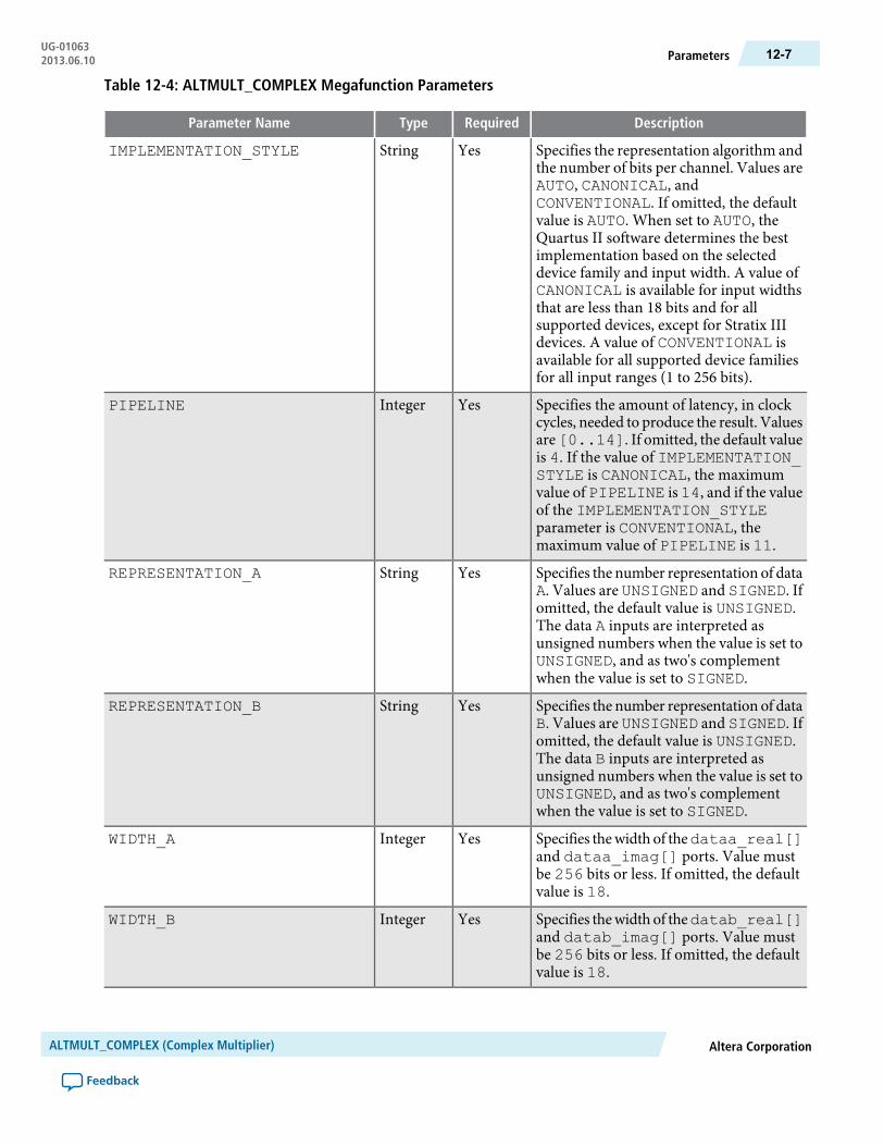
Table 12-4: ALTMULT_COMPLEX Megafunction Parameters
DescriptionRequiredTypeParameter Name
Specifies the representation algorithm andthe number of bits per channel. Values areAUTO, CANONICAL, andCONVENTIONAL. If omitted, the defaultvalue is AUTO. When set to AUTO, theQuartus II software determines the bestimplementation based on the selecteddevice family and input width. A value ofCANONICAL is available for input widthsthat are less than 18 bits and for allsupported devices, except for Stratix IIIdevices. A value of CONVENTIONAL isavailable for all supported device familiesfor all input ranges (1 to 256 bits).
YesStringIMPLEMENTATION_STYLE
Specifies the amount of latency, in clockcycles, needed to produce the result. Valuesare[0..14]. If omitted, the default valueis 4. If the value of IMPLEMENTATION_STYLE is CANONICAL, the maximumvalue of PIPELINE is 14, and if the valueof the IMPLEMENTATION_STYLEparameter is CONVENTIONAL, themaximum value of PIPELINE is 11.
YesIntegerPIPELINE
Specifies the number representation of dataA. Values are UNSIGNED and SIGNED. Ifomitted, the default value is UNSIGNED.The data A inputs are interpreted asunsigned numbers when the value is set toUNSIGNED, and as two's complementwhen the value is set to SIGNED.
YesStringREPRESENTATION_A
Specifies the number representation of dataB. Values are UNSIGNED and SIGNED. Ifomitted, the default value is UNSIGNED.The data B inputs are interpreted asunsigned numbers when the value is set toUNSIGNED, and as two's complementwhen the value is set to SIGNED.
YesStringREPRESENTATION_B
Specifies thewidth of thedataa_real[]and dataa_imag[] ports. Value mustbe 256 bits or less. If omitted, the defaultvalue is 18.
YesIntegerWIDTH_A
Specifies thewidth of thedatab_real[]and datab_imag[] ports. Value mustbe 256 bits or less. If omitted, the defaultvalue is 18.
YesIntegerWIDTH_B
Altera CorporationALTMULT_COMPLEX (Complex Multiplier)
Feedback
12-7ParametersUG-010632013.06.10

DescriptionRequiredTypeParameter Name
Specifies the width of the result_real[] and result_imag[] ports.Value must be 256 bits or less. If omitted,the default value is 36.
YesIntegerWIDTH_RESULT
This parameter is used for modeling andbehavioral simulation purposes. Create theALTMULT_COMPLEXmegafunction withthe MegaWizard Plug-in Manager tocalculate the value for this parameter.
NoStringINTENDED_DEVICE_FAMILY
Allows you to specify Altera-specificparameters in VHDL design files (.vhd).The default value is UNUSED.
NoStringLPM_HINT
Identifies the library of parameterizedmodules (LPM) entity name in VHDLdesign files.
NoStringLPM_TYPE
Design Example: Multiplication of 8-bit Complex Numbers Using CanonicalRepresentation
This design example uses the ALTMULT_COMPLEX megafunction to implement a complex multiplierwith an 8-bit input datawidth using the canonical representation. This example uses theMegaWizard Plug-InManager in the Quartus II software.
The following design files can be found in altmult_complex_DesignExample.zip:
complex_canonical.qar (archived Quartus II design files)
altmult_complex_ex_msim (ModelSim-Altera files)
Understanding the Simulation ResultsThe following settings are observed in this example:
• The widths of the data inputs are all set to 8 bits• The widths of the output ports are set to 16 bits• The asynchronous clear (aclr) and clock enable (ena) signals are enabled• Pipelining is enabled with an output latency of four clock cycles. Hence, the result is seen on the output
ports four clock cycles after the input data is available
The following figure shows the expected simulation results in the ModelSim-Altera software.
ALTMULT_COMPLEX (Complex Multiplier)Altera Corporation
Feedback
UG-01063Design Example: Multiplication of 8-bit Complex Numbers Using Canonical Representation12-8 2013.06.10
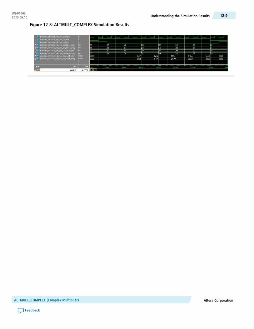
Figure 12-8: ALTMULT_COMPLEX Simulation Results
Altera CorporationALTMULT_COMPLEX (Complex Multiplier)
Feedback
12-9Understanding the Simulation ResultsUG-010632013.06.10

13ALTSQRT (Integer Square Root)
2013.06.10UG-01063 Subscribe Feedback
TheALTSQRTmegafunction implements a square root function that calculates the square root and remainderof an input.
The following figure shows the ports for the ALTSQRT megafunction.
Figure 13-1: ALTSQRT Ports
radical[]
inst
ALTSQRT[]
enaclk
q[]
aclr
remainder[]
FeaturesThe ALTSQRT megafunction offers the following features:
• Calculates the square root and the remainder of an input• Supports data width of 1–256 bits• Supports pipelining with configurable output latency• Supports optional asynchronous clear and clock enable input ports
Resource Utilization and PerformanceThe following table provides resource utilization and performance information for the ALTSQRTmegafunction.
ISO9001:2008Registered
© 2013 Altera Corporation. All rights reserved. ALTERA, ARRIA, CYCLONE, HARDCOPY, MAX, MEGACORE, NIOS, QUARTUS and STRATIXwords and logos are trademarks of Altera Corporation and registered in the U.S. Patent and Trademark Office and in other countries. All other wordsand logos identified as trademarks or service marks are the property of their respective holders as described at www.altera.com/common/legal.html.Altera warrants performance of its semiconductor products to current specifications in accordance with Altera's standard warranty, but reserves theright to make changes to any products and services at any time without notice. Altera assumes no responsibility or liability arising out of the applicationor use of any information, product, or service described herein except as expressly agreed to in writing by Altera. Altera customers are advised toobtain the latest version of device specifications before relying on any published information and before placing orders for products or services.
www.altera.com
101 Innovation Drive, San Jose, CA 95134

fMAX (MHz) 10
Logic Usage
Output latencyInput data
widthDevice family Adaptive Logic
Module (ALM)Dedicated Lo-gic Register
(DLR)
Adaptive Look-Up Table(ALUT)
5471402818
Stratix III 321900131520
711520256330
3501402818
Stratix IV 267940131520
661540256330
Verilog HDL PrototypeThe following Verilog HDL prototype is located in the Verilog Design File (.v) altera_mf.v in the <QuartusII installation directory>\eda\synthesis directory.
module altsqrt# (parameter lpm_hint = "UNUSED",parameter lpm_type = "altsqrt",parameter pipeline = 0,parameter q_port_width = 1,parameter r_port_width = 1,parameter width = 1)(input wire aclr,input wire clk,input wire ena,output wire [q_port_width-1:0] q,input wire [width-1:0] radical,output wire [r_port_width-1:0] remainder);endmodule
VHDL Component DeclarationThe VHDL component declaration is located in the VHDL Design File (.vhd) altera_mf_components.vhdin the <Quartus II installation directory>\libraries\vhdl\altera_mf directory.
component altsqrtgeneric (lpm_hint:string := "UNUSED";lpm_type:string := "altsqrt";pipeline:natural := 0;
10 The performance of the megafunction is dependant on the value of the maximum allowable ceiling fMAX thatthe selected device can achieve. Therefore, results may vary from the numbers stated in this column.
ALTSQRT (Integer Square Root)Altera Corporation
Feedback
UG-01063Verilog HDL Prototype13-2 2013.06.10

q_port_width:natural := 1;r_port_width:natural := 1;width:natural);port(aclr:in std_logic := '0';clk:in std_logic := '1';ena:in std_logic := '1';q:out std_logic_vector(Q_PORT_WIDTH-1 downto 0);radical:in std_logic_vector(WIDTH-1 downto 0);remainder:out std_logic_vector(R_PORT_WIDTH-1 downto 0));end component;
VHDL LIBRARY_USE DeclarationThe VHDL LIBRARY-USE declaration is not required if you use the VHDL Component Declaration.
LIBRARY altera_mf;USE altera_mf.altera_mf_components.all;
PortsThe following tables list the input and output ports for the ALTSQRT megafunction.
Table 13-1: ALTSQRT Megafunction Input Ports
DescriptionRequiredPort Name
Data input port. The size of the input port depends on the WIDTH parametervalue.
Yesradical[]
Active high clock enable input port.Noena
Clock input port that provides pipelined operation for the ALTSQRTmegafunction. For the values of PIPELINE parameter other than 0 (defaultvalue), the clock port must be connected.
Noclk
Asynchronous clear input port. that can be used at any time to reset the pipelineto all 0s, asynchronously to the clock signal.
Noaclr
Table 13-2: ALTSQRT Megafunction Output Ports
DescriptionRequiredPort Name
The square root of the radical. The size of the remainder[] port depends onthe R_PORT_WIDTH parameter value.
Yesremainder[]
Data output. The size of the q[] port depends on the Q_PORT_WIDTHparameter value.
Yesq[]
Altera CorporationALTSQRT (Integer Square Root)
Feedback
13-3VHDL LIBRARY_USE DeclarationUG-010632013.06.10
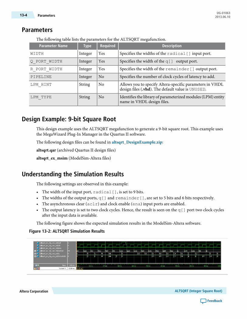
ParametersThe following table lists the parameters for the ALTSQRT megafunction.
DescriptionRequiredTypeParameter Name
Specifies the widths of the radical[] input port.YesIntegerWIDTH
Specifies the width of the q[] output port.YesIntegerQ_PORT_WIDTH
Specifies the width of the remainder[] output port.YesIntegerR_PORT_WIDTH
Specifies the number of clock cycles of latency to add.NoIntegerPIPELINE
Allows you to specify Altera-specific parameters in VHDLdesign files (.vhd). The default value is UNUSED.
NoStringLPM_HINT
Identifies the library of parameterizedmodules (LPM) entityname in VHDL design files.
NoStringLPM_TYPE
Design Example: 9-bit Square RootThis design example uses the ALTSQRT megafunction to generate a 9-bit square root. This example usesthe MegaWizard Plug-In Manager in the Quartus II software.
The following design files can be found in altsqrt_DesignExample.zip:
altsqrt.qar (archived Quartus II design files)
altsqrt_ex_msim (ModelSim-Altera files)
Understanding the Simulation ResultsThe following settings are observed in this example:
• The width of the input port, radical[], is set to 9 bits.• The widths of the output ports, q[] and remainder[], are set to 5 bits and 6 bits respectively.• The asynchronous clear (aclr) and clock enable (ena) input ports are enabled.• The output latency is set to two clock cycles. Hence, the result is seen on the q[] port two clock cycles
after the input data is available.
The following figure shows the expected simulation results in the ModelSim-Altera software.
Figure 13-2: ALTSQRT Simulation Results
ALTSQRT (Integer Square Root)Altera Corporation
Feedback
UG-01063Parameters13-4 2013.06.10
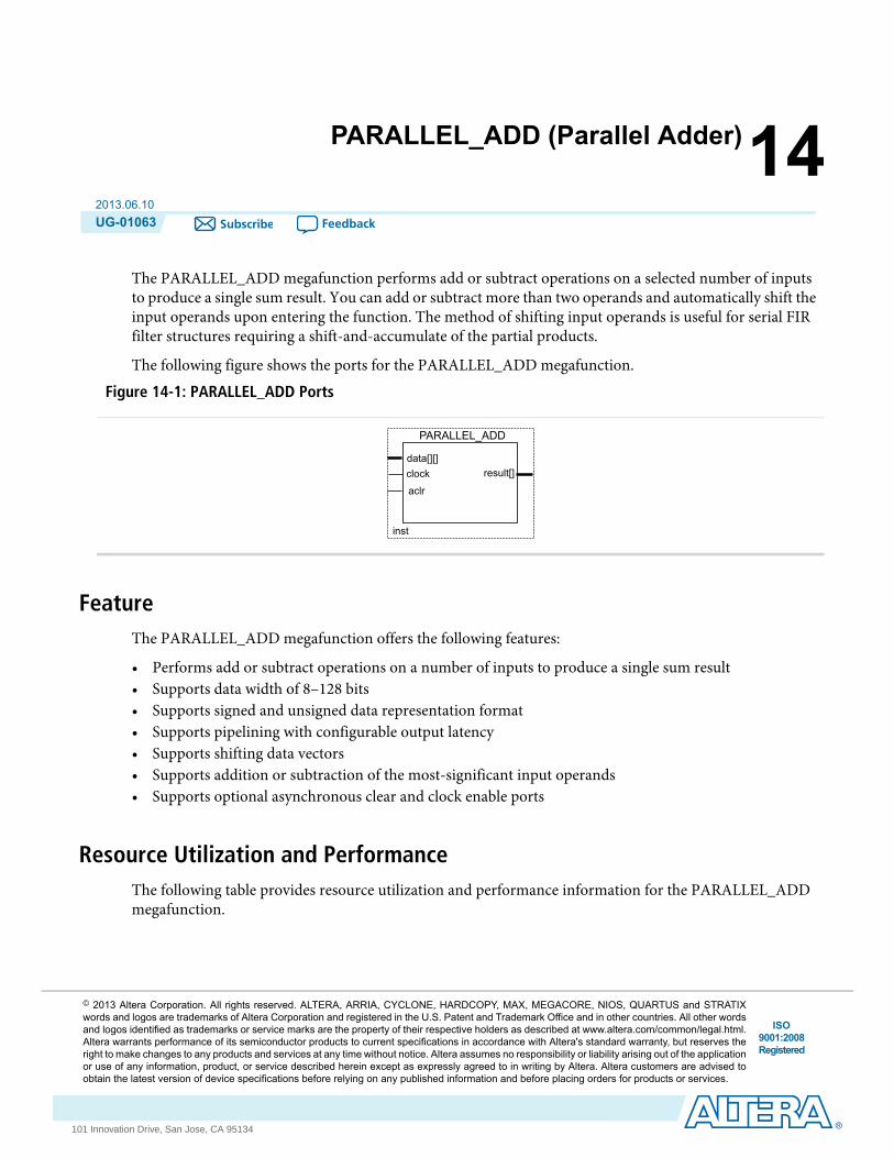
14PARALLEL_ADD (Parallel Adder)
2013.06.10UG-01063 Subscribe Feedback
The PARALLEL_ADD megafunction performs add or subtract operations on a selected number of inputsto produce a single sum result. You can add or subtract more than two operands and automatically shift theinput operands upon entering the function. The method of shifting input operands is useful for serial FIRfilter structures requiring a shift-and-accumulate of the partial products.
The following figure shows the ports for the PARALLEL_ADD megafunction.
Figure 14-1: PARALLEL_ADD Ports
data[][]
inst
PARALLEL_ADD
clock
aclr
result[]
FeatureThe PARALLEL_ADD megafunction offers the following features:
• Performs add or subtract operations on a number of inputs to produce a single sum result• Supports data width of 8–128 bits• Supports signed and unsigned data representation format• Supports pipelining with configurable output latency• Supports shifting data vectors• Supports addition or subtraction of the most-significant input operands• Supports optional asynchronous clear and clock enable ports
Resource Utilization and PerformanceThe following table provides resource utilization and performance information for the PARALLEL_ADDmegafunction.
ISO9001:2008Registered
© 2013 Altera Corporation. All rights reserved. ALTERA, ARRIA, CYCLONE, HARDCOPY, MAX, MEGACORE, NIOS, QUARTUS and STRATIXwords and logos are trademarks of Altera Corporation and registered in the U.S. Patent and Trademark Office and in other countries. All other wordsand logos identified as trademarks or service marks are the property of their respective holders as described at www.altera.com/common/legal.html.Altera warrants performance of its semiconductor products to current specifications in accordance with Altera's standard warranty, but reserves theright to make changes to any products and services at any time without notice. Altera assumes no responsibility or liability arising out of the applicationor use of any information, product, or service described herein except as expressly agreed to in writing by Altera. Altera customers are advised toobtain the latest version of device specifications before relying on any published information and before placing orders for products or services.
www.altera.com
101 Innovation Drive, San Jose, CA 95134
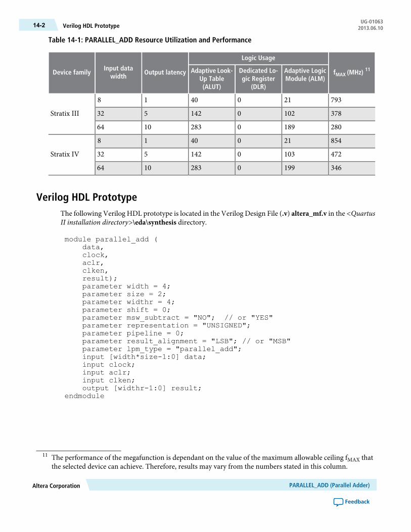
Table 14-1: PARALLEL_ADD Resource Utilization and Performance
fMAX (MHz) 11
Logic Usage
Output latencyInput data
widthDevice family Adaptive Logic
Module (ALM)Dedicated Lo-gic Register
(DLR)
Adaptive Look-Up Table(ALUT)
7932104018
Stratix III 3781020142532
28018902831064
8542104018
Stratix IV 4721030142532
34619902831064
Verilog HDL PrototypeThe following Verilog HDL prototype is located in the Verilog Design File (.v) altera_mf.v in the <QuartusII installation directory>\eda\synthesis directory.
module parallel_add (data,clock,aclr,clken,result);parameter width = 4;parameter size = 2;parameter widthr = 4;parameter shift = 0;parameter msw_subtract = "NO"; // or "YES"parameter representation = "UNSIGNED";parameter pipeline = 0;parameter result_alignment = "LSB"; // or "MSB"parameter lpm_type = "parallel_add";input [width*size-1:0] data;input clock;input aclr;input clken;output [widthr-1:0] result;
endmodule
11 The performance of the megafunction is dependant on the value of the maximum allowable ceiling fMAX thatthe selected device can achieve. Therefore, results may vary from the numbers stated in this column.
PARALLEL_ADD (Parallel Adder)Altera Corporation
Feedback
UG-01063Verilog HDL Prototype14-2 2013.06.10

VHDL Component DeclarationThe VHDL component declaration is located in the VHDL Design File (.vhd) altera_mf_components.vhdin the <Quartus II installation directory>\libraries\vhdl\altera_mf directory.
component parallel_addgeneric (
width : natural := 4;size : natural := 2;widthr : natural := 4;shift : natural := 0;msw_subtract : string := "NO";representation : string := "UNSIGNED";pipeline : natural := 0;result_alignment : string := "LSB";lpm_hint: string := "UNUSED";lpm_type : string := "parallel_add");
port (data:in altera_mf_logic_2D(size - 1 downto 0,width- 1 downto 0);
clock : in std_logic := '1';aclr : in std_logic := '0';clken : in std_logic := '1';result : out std_logic_vector(widthr - 1 downto 0));
end component;
VHDL LIBRARY_USE DeclarationThe VHDL LIBRARY-USE declaration is not required if you use the VHDL Component Declaration.
LIBRARY altera_mf;USE altera_mf.altera_mf_components.all;
PortsThe following tables list the input and output ports of the PARALLEL_ADD megafunction.
Table 14-2: PARALLEL_ADD Megafunction Input Ports
DescriptionRequiredPort Name
Data input to the parallel adder. Input port [SIZE - 1 DOWNTO 0, WIDTH-1 DOWNTO 0] wide.
Yesdata[]
Clock input to the parallel adder. This port is required if the PIPELINE parameterhas a value of greater than 0.
Noclock
Clock enable to the parallel adder. If omitted, the default value is 1.Noclken
Active high asynchronous clear input to the parallel adder.Noaclr
Altera CorporationPARALLEL_ADD (Parallel Adder)
Feedback
14-3VHDL Component DeclarationUG-010632013.06.10
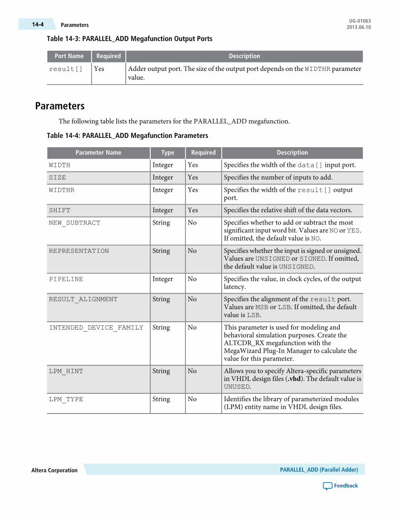
Table 14-3: PARALLEL_ADD Megafunction Output Ports
DescriptionRequiredPort Name
Adder output port. The size of the output port depends on the WIDTHR parametervalue.
Yesresult[]
ParametersThe following table lists the parameters for the PARALLEL_ADD megafunction.
Table 14-4: PARALLEL_ADD Megafunction Parameters
DescriptionRequiredTypeParameter Name
Specifies the width of the data[] input port.YesIntegerWIDTH
Specifies the number of inputs to add.YesIntegerSIZE
Specifies the width of the result[] outputport.
YesIntegerWIDTHR
Specifies the relative shift of the data vectors.YesIntegerSHIFT
Specifies whether to add or subtract the mostsignificant input word bit. Values areNO orYES.If omitted, the default value is NO.
NoStringNEW_SUBTRACT
Specifies whether the input is signed or unsigned.Values are UNSIGNED or SIGNED. If omitted,the default value is UNSIGNED.
NoStringREPRESENTATION
Specifies the value, in clock cycles, of the outputlatency.
NoIntegerPIPELINE
Specifies the alignment of the result port.Values are MSB or LSB. If omitted, the defaultvalue is LSB.
NoStringRESULT_ALIGNMENT
This parameter is used for modeling andbehavioral simulation purposes. Create theALTCDR_RX megafunction with theMegaWizard Plug-In Manager to calculate thevalue for this parameter.
NoStringINTENDED_DEVICE_FAMILY
Allows you to specify Altera-specific parametersin VHDL design files (.vhd). The default value isUNUSED.
NoStringLPM_HINT
Identifies the library of parameterized modules(LPM) entity name in VHDL design files.
NoStringLPM_TYPE
PARALLEL_ADD (Parallel Adder)Altera Corporation
Feedback
UG-01063Parameters14-4 2013.06.10

Design Example: Shift AccumulatorThis design example uses the LPM_MULT and PARALLEL_ADD megafunctions to generate a shiftaccumulator. This function implements the shift-and-accumulate operation after the multiplication processin a design block, such as a serial FIR filter. This example uses the MegaWizard Plug-In Manager in theQuartus II software.
The following design files can be found in parallel_adder_DesignExample.zip:
• shift_accum.qar (archived Quartus II design files)• parallel_adder_ex_msim (ModelSim-Altera files)
Understanding the Simulation ResultsThe following settings are observed in this example:
• The widths of the input ports, dataa[] and datab[], are set to 9 bits• The width of the output port, resultant[], is set to 10 bits• The asynchronous clear (aclr) and clock enable (clocken) input ports are enabled• The latency is set to one clock cycle for the multiplier and one clock cycle for the parallel adder, resulting
in a total output latency of two clock cycles. Hence, the result is seen on the resultant[] port twoclock cycles after the input data is available
The following figure shows the expected simulation results in the ModelSim-Altera software.
Figure 14-2: PARALLEL_ADDER Simulation Results
At start up, an undefined value is seen on the resultant[] port, but this value is merely due tothe behavior of the system during start-up and hence, can be ignored
Note:
Altera CorporationPARALLEL_ADD (Parallel Adder)
Feedback
14-5Design Example: Shift AccumulatorUG-010632013.06.10

15Document Revision History
2013.06.10UG-01063 Subscribe Feedback
The following table lists the revision history for this document.
Table 15-1: Document Revision History
ChangesVersionDate
• Added ALTERA_MULT_ADD (Multiply-Adder) on page 8-1.• Removed the following obsolete megafunctions: LPM_ABS,
ALTACCUMULATE, ALTMULT_ACCUM, ALTMULT_ADD.• Updated ALTMULT_ACCUM (Multiply-Accumulate) on page 10-1
to include an obsolescence note and remove Arria V, Cyclone V, andStratix V devices information.
• Updated ALTMULT_ADD (Multiply-Adder) on page 11-1 to includean obsolescence note and remove Arria V, Cyclone V, and Stratix Vdevices information.
2013.06.10June 2013
• Updated Table 52 on page 63 to include Stratix V information foraccum_sload port.
• Updated Table 54 on page 65 to include Stratix V information forPORT_SIGNA and PORT_SIGNB parameters.
3.1February 2013
• Added Arria V and Cyclone V device support.• Updated the parameter description for the following section:
• ALTMULT_ACCUM (Multiply-Accumulate)• ALTMULT_ADD (Multiply-Add)
• Added the Double Accumulator section.
3.0February 2012
• Updated architecture information for the following sections:
• ALTMULT_ACCUM (Multiply-Accumulate)• ALTMULT_ADD (Multiply-Add)• ALTMULT_COMPLEX (Complex Multiplier)
• Added specification information for all megafunctions
2.0July 2010
Initial release.1.0November 2009
ISO9001:2008Registered
© 2013 Altera Corporation. All rights reserved. ALTERA, ARRIA, CYCLONE, HARDCOPY, MAX, MEGACORE, NIOS, QUARTUS and STRATIXwords and logos are trademarks of Altera Corporation and registered in the U.S. Patent and Trademark Office and in other countries. All other wordsand logos identified as trademarks or service marks are the property of their respective holders as described at www.altera.com/common/legal.html.Altera warrants performance of its semiconductor products to current specifications in accordance with Altera's standard warranty, but reserves theright to make changes to any products and services at any time without notice. Altera assumes no responsibility or liability arising out of the applicationor use of any information, product, or service described herein except as expressly agreed to in writing by Altera. Altera customers are advised toobtain the latest version of device specifications before relying on any published information and before placing orders for products or services.
www.altera.com
101 Innovation Drive, San Jose, CA 95134