
Epoxy Colorado - Greeley Epoxy Garage Floor in Greeley, Colorado
Upload
deepesh-kumarCategory
view
15download
3description

Chapter 11
Progressive Failure Analysisof Glass/Epoxy Compositesat Low Temperatures
Mohammad Amin Torabizadeh andAbdolhossein Fereidoon
Additional information is available at the end of the chapter
http://dx.doi.org/10.5772/55093
1. Introduction
Fiber reinforced composite materials have been increasingly used as structural membersin many structures such as airplane. The advantages of these materials are derived fromtheir high strength, stiffness and damping together with low specific weight. Lowtemperature mechanical properties of glass fiber-reinforced epoxy have to be assessed,because of composite materials are subjected to low temperatures in service. Experimen‐tal or analytical investigation on the tensile failure behavior of glass/epoxy laminatedcomposite with/or without stress concentration subjected to thermo-mechanical staticloadings at low temperatures has not been done yet. In the present work, a model wasdeveloped to perform the progressive failure analysis of quasi isotropic composite platesat low temperatures. The initial failure load is calculated by means of an elastic stressanalysis. The load is increased step by step. For each given load, the stresses are evaluatedand the appropriate failure criterion is applied to inspect for possible failure. For the failedelement, material properties are modified according to the failure mode using a non-zero stiffness degradation factor. Then, the modified Newton–Raphson iteration is carriedout until convergence is reached. This analysis is repeated for each load increment untilthe final failure occurs and the ultimate strength is determined. The present method yieldsresults in a reasonable agreement with the experimental data at room temperature and-60 ºC. The effect of low temperature on the failure mechanism of the plates was alsodetermined.
© 2013 Torabizadeh and Fereidoon; licensee InTech. This is an open access article distributed under the termsof the Creative Commons Attribution License (http://creativecommons.org/licenses/by/3.0), which permitsunrestricted use, distribution, and reproduction in any medium, provided the original work is properly cited.

2. Materials and mechanical testing
2.1. Material properties
Unidirectional glass fibers have been used in this investigation as reinforcing material, whileepoxy resin has been utilized as the matrix material. Hand lay-up method was used to fabricatethin laminates with epoxy resin ML-506 with hardener HA11. Test specimens were cut fromlaminates according to relevant standard codes. All specimens had a constant cross sectionwith tabs bonded to the ends. The fiber volume fraction of the composites was 55%.
2.2. Mechanical test equipments
The specimens are tested from beginning to the failure mode both at room and low tempera‐tures. All tests were conducted under displacement control condition using Instron 5582machine adaptable for cryogenic service by an environmental chamber. The displacement ratewas 2 mm/min. Environmental chamber has the ability to cool down the temperature to -196°C by evaporating liquid cryogenic Nitrogen. During the tests, a pressurizing device is usedto control the cooling time from room temperature to -20 °C and -60 °C and maintain anevaporating pressure of 152 kPa. In order to reach thermal equilibrium in mechanical parts ofmachine one hour prior to first time of testing, temperature of environmental chamber waskept at desired low temperatures. Since composite materials require more time than metalmaterials to reach thermal equilibrium states in low temperatures, specimens stayed in aconstant low temperature for at least an hour prior to start loading. Environmental chamberwas equipped with a fan to perform a uniform temperature. A digital thermometer wasmounted inside of environmental chamber to monitor active temperature during the tests.Experimental set up for mechanical tests at different temperature is shown in Figure 1.
Figure 1. Experimental setup for mechanical tests at both room and low temperatures
Materials Science - Advanced Topics250

3. Material characterization
In order to apply progressive damage modeling to a laminated composite, mechanicalproperties of unidirectional laminates should be assessed. For this purpose test specimens wasfabricated for tensile, compressive and shear loading in longitudinal and transverse direction.In this section, for each case, specimen dimensions and experimental results are reported. Alsosome master curves are illustrated to predict mechanical properties in the assumed tempera‐ture range. Finally all of mechanical properties are assessed by a regression function.
3.1. Tensile test
The unidirectional glass fiber-reinforced epoxy which composed of ten plies was used in thistest; the total thickness of the laminate is 2 mm. Unidirectional tensile specimens were cut outof the laminates in both fiber and matrix directions (longitudinal and transverse) according toASTM D3039 [1]. Woven glass/epoxy tabs with tapered ends were locally bonded on each sideof the specimens. These tabs allow a smooth load transfer from the grip to the specimenespecially for low temperature test. The geometries of the specimens for longitudinal andtransverse tensile tests are shown in Figure 2.
Dimensions(mm)
5215138
2.128.43
3
2
1
TtWLLL
Dimensions(mm)
52
2512525
2
1
TtWLL
Longitudinal tensile specimen ([0]10)
Transverse tensile specimen ([90]10)
Figure 2. Geometry of the specimens for longitudinal and transverse tensile tests at different temperatures
The purpose of the static tensile tests was to determine the low temperature effects on thetensile strength, Young modulus and ultimate strain of unidirectional laminates in longitudi‐nal and transverse directions. Figure 3 show the typical stress-strain behavior of unidirectionallaminate under tensile loads in longitudinal direction at room temperature, -20 °C and -60°C. The laminate exhibits a linear elastic behavior until breakage and the slope of the stress-strain curve increases as the temperature decreases. On the other hand, by decreasing tem‐perature, strain to failure decreases slightly. The strain to failure reduction was very small(from 0.037, at room temperature, to 0.032 at -60 °C). However, the strength and stiffnessincrease significantly as temperature decreases. The average value of tensile strength increasesfrom 700.11 MPa, at room temperature, to 784.98 MPa, at -60 °C, whereas the Young modulusalso increases from 23.05 GPa at room temperature, to 28.65 GPa at -60 °C. Some authors eportedincreasing of tensile strength and modulus for a UD glass-epoxy composite at cryogenictemperatures [10], [38]. Consequently, it was speculated that the brittleness of the fibers had
Progressive Failure Analysis of Glass/Epoxy Composites at Low Temperatureshttp://dx.doi.org/10.5772/55093
251

a major influence on the stiffness and strength increase of UD composites at low temperatures.Especially the brittleness of the fibers rapidly increased within a temperature range from RTto -60 °C which was indicated by Ref [10].
0
200
400
600
800
0 0.01 0.02 0.03
Long
itudi
nal t
ensi
le st
ress
(MPa
)
Strain
RT
-20
-60
ºCºC
Figure 3. Typical stress-strain behavior of unidirectional laminate under tensile loads in longitudinal direction at roomtemperature, -20 °C and -60 °C
0
20
40
60
80
0 0.005 0.01 0.015 0.02
Tran
sver
se te
nsile
stre
ss
(M
Pa)
Strain
RT-20-60
ºCºC
Figure 4. Typical stress-strain behavior of unidirectional laminate under tensile loads in transverse direction at roomtemperature, -20 °C and -60 °C
Figure 4 show the load-deflection curve of unidirectional laminates under tensile loads intransverse direction. The behavior is the same as described in the previous tests. The onlydifference is that the stress-strain curve in this case showed insignificant nonlinearity beforereaching the maximum stress, which is due to the nature of the plasticity of epoxy. It was
Materials Science - Advanced Topics252

observed because the composite becomes more brittle in low temperatures, this nonlinearitybehavior of matrix decreased by decreasing temperature in Figure 4 and Ref. [37]. Typicalresults was also reported that both transverse tensile strength and stiffness increased bydecreasing temperature from RT for glass-epoxy composites [39].
Failure regions of the composite specimens at different temperatures in longitudinal andtransverse directions under tensile loading are shown in Figure 5 and Figure 6 respectively. Itis found that in the case of longitudinal tension, the failure mechanism changes with temper‐ature while no significant change was observed on the transverse direction.
Figure 5. Failure regions of the composite specimens at different temperatures in longitudinal direction under tensileloading
Figure 6. Failure regions of the composite specimens at different temperatures in transverse direction under tensileloading
Progressive Failure Analysis of Glass/Epoxy Composites at Low Temperatureshttp://dx.doi.org/10.5772/55093
253

For the longitudinal direction, from a visual inspection of the damage surfaces, a significantchange could be observed in the fracture surface at room temperature to -60 ºC. There is a smallamount of tab de-bonding near the gauge area for room temperature tested specimens. Also,fiber breakage which is more visible for low temperature case was occurred. At low temper‐ature, due to weak interface between the fiber and matrix, fibers lose their bonds to the matrix.Moreover, matrix cracking and fiber pull-out were also observed. At shown in Figure 5,damage area was more limited at RT while by decreasing temperature to -60 °C; the damagewas extend further and covered the entire gauge region. In the transverse tension loading, netmatrix failure observed near the gauge area. The major difference between room temperatureand low temperatures tests in this case is that in low temperatures (Figure 6) small fiber-matrixdeboning is observed which is not obvious in room temperature specimens. Also, bigger failureregion of matrix is obvious at low temperatures. There is no significant change in failuremechanism for specimens at -20 ºC and -60 ºC.
3.2. Compression test
The specimens used for compression test had the same material as those of the tensile testexcept that these specimens were made of fifteen plies so that the total thickness is 3 mm.Unidirectional compression specimens were cut in the longitudinal and transverse directionsfor longitudinal and transverse compression tests and also a fixture is used for the testsaccording to ASTM D3410 [2]. The geometries of the specimens are shown in Fig. 2. Wovenglass/epoxy tabs were locally bonded on each side of the specimens to reduce the grippingeffects. Also, a thin Teflon sheet, as a weakly bonded area, was inserted on each of thecontacting surfaces between the specimens and the tabs to reduce the gripping effects in fibercompression specimens.
Dimensions(mm)
63
102065
2
1
TtWLL
Dimensions (mm)
63
252065
2
1
TtWLL
Figure 1. Geometry of the specimens for longitudinal and transverse compressive tests at different temperatures
Fiber compression specimen ([0]15)
Matrix compression specimen ([90]15)
Figure 7. Geometry of the specimens for longitudinal and transverse compressive tests at different temperatures
In order to determine the effect of low temperature service on the strength and strain to failureof composite specimens in longitudinal and transverse directions, a set of experimental testswere performed. For this reason, a special fixture recommended in ASTM D3410 was used to
Materials Science - Advanced Topics254

prevent possible buckling. Figure 8 illustrate typical stress-strain behavior of compositelaminate under compressive loading in longitudinal direction at various temperatures. Asshown, the stress-strain relation is slightly nonlinear and final failure occurs catastrophicallyin all cases. The main specific property of longitudinal compressive stress-strain curves is thatagainst other nonlinear stress-strain curves of UD composite in longitudinal or transversedirections, these curves exhibit positive curvature. This may be due to interface bondingbetween matrix and fibers. Imperfect fiber-matrix bonding is a manufacturing defect that iscreated during curing process. This defect influences the role of the matrix that supports thefibers when the composite is under compression [28], [29]. From stress-strain curves, it seemsthat by increasing compression in longitudinal direction, this bonding becomes grater and therole of matrix against microbuckling of fibers is more highlighted. As shown in the figure,significant non-linear deformation was often observed before the maximum load [30], [31],and this behavior was associated to the plastic deformation of the polymeric matrix. Com‐pressive strength in longitudinal direction increases significantly by decreasing temperature(from 570.37 MPa at room temperature, to 731.94 MPa at -60 °C).
0
200
400
600
800
0.0 0.1 0.2 0.3Long
itudi
nal C
ompr
essi
ve st
ress
(M
Pa)
Strain
RT
-20-60
ºCºC
Figure 8. Typical stress-strain behavior of unidirectional laminate under compressive loads in longitudinal direction atroom temperature, -20 °C and -60 °C
Figure 9 depict stress-strain curves of unidirectional composite under transverse compressiveloading at different temperatures. Again significant increase in strength of composite wasobserved by decreasing temperature (from 122.12 MPa at room temperature, to 186.22 MPa at-60 °C). Typical behavior was reported by [32] for glass-epoxy composites. But in this caseagainst other directions of loading, by decreasing temperature, transverse compressivestiffness was decreased and strain to failure was increased significantly. The reason of theobserved phenomenon in this type of loading is unknown and it is interested to investigatemore about this behavior in future works.
Progressive Failure Analysis of Glass/Epoxy Composites at Low Temperatureshttp://dx.doi.org/10.5772/55093
255

0
40
80
120
160
200
0 0.1 0.2 0.3
Tran
sver
se c
ompr
essi
ve st
ress
(M
Pa)
Strain
RT
-20
-60
ºCºC
Figure 9. Typical stress-strain behavior of unidirectional laminate under compressive loads in transverse direction atroom temperature, -20 °C and -60 °C
Figure 10 and Figure 11 show failed specimens under compressive loading in longitudinal andtransverse directions at different temperatures, respectively.
Figure 10. Failure regions of the composite specimens at different temperatures in longitudinal direction under com‐pressive loading
Figure 11. Failure regions of the composite specimens at different temperatures in transverse direction under com‐pressive loading
Materials Science - Advanced Topics256

The main failure mode of specimens in this case is micro buckling of fibers in shear orextensional mode. Also, in this case, there is a small amount of tab deboning near the gaugearea for room temperature specimens. The change in the mechanical response with decreasingtemperature is associated with a change in failure modes. As shown in Figure 11, failureoccurred at the middle of specimen under micro-buckling failure mode. The difference is that,in low temperature cases, more fiber pull-out was occurred. Also, extensive deboning betweenfibers and the matrix was also observed because of weaker fiber and matrix bonding at lowtemperatures. In this case, only at low temperatures failed specimens fractured in two separateparts. In the case of compression failure in the transverse direction at low temperature, thefailure area is much more than the room temperature specimens. Also at room temperature,specimen is not fractured in two separate parts. This is because of major effects of lowtemperature on mechanical properties of epoxy matrix of composites. In this case, there is nosignificant change in failure mechanism for specimens at -20 ºC and -60 ºC. It is found the roleplayed by two dominant damage mechanisms (decohesion at the interface and shear bandformation in the matrix) in controlling the composite strength. On the other hand, if decohesionis inhibited, failure took place by the development of shear bands in the matrix whichpropagated through the microstructure at angle of ±45o with respect to the plane perpendicularto the compression axis [32]. The compressive strength was slightly higher than the matrixstrength under compression due to the additional strengthening provided by the fibers.Parametric studies showed that other factors (such as the matrix friction angle, the interfacefracture energy and the thermo-elastic residual stresses) exerted a secondary influence on thecompressive strength of PMC under transverse compression [32]. But the matrix is moresusceptible to the formation of shear bands. The angle formed between the failure plane andin-plane loading direction is slightly above 45o and typical values reported are in the range50-56o [40]-[42].
3.3. In-plane shear test
In the following, method of static experiments for characterizing material properties under in-plane shear loading is illustrated. Among numerous testing methods, the three-rail shear testmethod, described by the ASTM A4255 [3], is a fairly reliable technique. This method ismodified by Shokrieh [28]. He developed new specimen by inserting notches into the edgesof specimen. The reason behind the insertion of notches at the locations of stress concentrationsis to replace a very sharp crack with a blunt crack with much lower stress concentration factor.To increase the stability of the specimen during the test, a [0,90]s configuration is selected inthis test. The specimen and the dimension are shown in Figure 12.
Electric strain gauges were used to measure the strains of the specimens during the shear tests.The strain gauges are attached to the specimens in the direction of 45°. The strain gauges andlead wires were manufactured by TML Corporation for low temperature ranges. However,since the changing in temperature would also affect the strain in strain gauges, Wheatstonehalf bridge circuit has been used to reduce this unfavorable effect.
Progressive Failure Analysis of Glass/Epoxy Composites at Low Temperatureshttp://dx.doi.org/10.5772/55093
257

Dimensions (mm)
25.15.1
95.1113385414
55.5895.21
136
4
3
2
1
thicknesshHDWLLLLL
Figure 12. Geometry of the specimens for in-plane shear tests at different temperatures
Figure 13 show the stress-strain behavior of modified specimen under in-plane shear loadingsat room temperature, -20 °C and -60 °C. As shown, this behavior is highly nonlinear for alltemperature tests. Also, as temperature decreases to -60 °C from the room temperature, boththe in-plane shear modulus and strength increased significantly.
0
30
60
90
120
0 0.01 0.02 0.03 0.04
Shea
r stre
ss (M
Pa)
Strain
RT
-20
-60
ºC
ºC
Figure 13. Typical stress-strain behavior of unidirectional laminate under in-plane shear loading at room temperature,-20 °C and -60 °C
Materials Science - Advanced Topics258

For metallic materials, the linear region of the stress-strain curve corresponds to elasticdeformation and the nonlinear region to plastic deformation. However, when working withnon-crystalline substances (such as epoxy), the glass transition temperature (Tg) determineswhether a material can exhibit viscous, or non-linear, behavior. Below the glass transitiontemperature a non-crystalline material is considered an amorphous solid, above it a rubberysolid and, as the temperature increases, a viscous liquid [33]. A non-crystalline material suchas a polymer can only exhibit viscous behavior above Tg; below Tg, the material will fail beforeit plastically deforms. All of the tests in the current study were conducted well below Tg forthe epoxy resin (≈157 °C). This indicates that the nonlinear regions of the shear stress-shearstrain curves generated by the tests at room and low temperatures are not the result of viscous,or plastic, deformation [37]. This nonlinear behavior is thought to be the result of micro-crackaccumulation throughout the matrix. The extensive nonlinear region displayed in the roomtemperature stress-strain curves would correspond to a high density of micro-cracks through‐out the material (Figure 13). The more limited nonlinear region in the curves generated fromthe tests done at low temperatures imply that there is a progressive decrease in micro-crackaccumulation within the specimen with decreasing temperature. Reduction the nonlinearregion of stress-strain curves at low temperatures also confirmed by a suitable candidate modelto study the nonlinear behavior of composites under shear loading which was proposed byHahn and Tsai [28]. Parameter of material nonlinearity decreased from 1.76e-8 MPa-3 at roomtemperature to 1.33e-8 MPa-3 at -60 ºC. Figure 14 show tested specimens and failure regionsunder in-plane shear loading at different temperatures. As shown in the figure, more damagedarea was observed with decreasing temperature from room temperature to -60 ºC.
Figure 14. Tested specimens under shear loading at different temperatures
3.4. Master curves for mechanical properties
Figure 15 show the experimental values of tensile and compressive strengths for unidirectionallaminates at different temperatures in longitudinal and transverse directions with theircalculated standard deviations.
Progressive Failure Analysis of Glass/Epoxy Composites at Low Temperatureshttp://dx.doi.org/10.5772/55093
259

(a) (b
0
200
400
600
800
500
600
700
800
900
1000
-70 -45 -20 5 30
Long
itudi
nal c
ompr
essi
ve st
reng
th
(MPa
)
Long
itudi
nal t
ensi
le st
reng
th
(MPa
)
Temperature (ºC)
Longitudinal tensile strength
Longitudinal compressive strength
0
50
100
150
200
250
60
70
80
90
100
-70 -45 -20 5 30
Tran
sver
se c
ompr
essi
ve st
reng
th
(MPa
)
Tran
sver
se te
nsile
stre
ngth
(M
Pa)
Temperature (ºC)
Transverse tensile strengthTransverse compressive strength
Figure 15. Experimental values of the tensile and compressive strengths for unidirectional laminates at different tem‐perature in a) longitudinal and b) transverse directions
In each case in the above figures, by a polynomial curve fitting to experimental data, theincreasing trend of strengths by decreasing the temperature is shown. However, the increasingrate of compressive strength by decreasing temperature is more for that of the tensile strengthin both longitudinal and transverse directions. Figure 16 show experimental values of tensilemodulus for unidirectional laminates at different temperatures in longitudinal and transversedirections. Both longitudinal and transverse tensile modulus increased by decreasing temper‐ature to -60 ºC.
0
4
8
12
15
30
45
60
-70 -45 -20 5 30
Tran
sver
se te
nsile
mod
ulus
(G
Pa)
Long
itudi
nal t
ensi
le m
odul
us
(GPa
)
Temperature (ºC)
Longitudinal tensile modulusTransverse tensile modulus
Figure 16. Experimental values of compressive strength for unidirectional laminates at different temperature in longi‐tudinal and transverse directions
Decreasing temperature, in this case, has lower effect on the final failure mode of the com‐pression tests of the unidirectional plies in longitudinal and transverse directions at varioustemperatures in comparison with the previous one. Experimental magnitudes of shear strength
Materials Science - Advanced Topics260

and modulus at different temperatures are compared in Figure 17. In the case of shear loading,low temperature has major effect on mechanical properties of composites.
0
2
4
55
85
115
145
-70 -45 -20 5 30
Shea
r mod
ulus
(GPa
)
Shea
r stre
ngth
(M
Pa)
Temperature (ºC)
Shear strengthShear modulus
Figure 17. Experimental values of shear strength and modulus for cross ply laminates at different temperatures
Temperature effects on mechanical properties of UD composites which are plotted in Figure15 to Figure 17 can be assessed also using a regression function defined by:
M (T )=αT 2−βT + γ
where, M and T are the mechanical property and temperature, respectively. Also α, β and γare the material constants. The values for α, β, γ and R (the correlation coefficient) are givenin Table 1.
Material constants α β γ R
Longitudinal compressive strength 0.0093 1.5706 604.05 0.9575
Transverse compressive strength 0.0121 0.3784 124.04 0.9678
Longitudinal tensile strength 0.0098 0.3808 718.52 0.9642
Transverse tensile strength 0.0010 0.0789 70.390 0.9622
In-plane shear strength 0.0058 0.0341 65.339 0.9682
Longitudinal modulus 0.0011 0.0326 22.800 0.9666
Transverse modulus 0.0007 0.0420 6.1913 0.9920
In-plane shear modulus 0.0002 0.0184 2.477 0.9769
Table 1. Material constants and correlation coefficients -60 °C ≤ T ≤ 23 °C
Progressive Failure Analysis of Glass/Epoxy Composites at Low Temperatureshttp://dx.doi.org/10.5772/55093
261
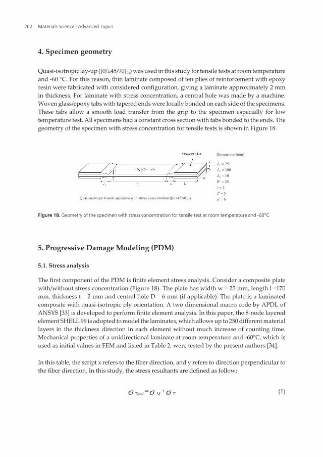
4. Specimen geometry
Quasi-isotropic lay-up ([0/±45/90]2s) was used in this study for tensile tests at room temperatureand -60 °C. For this reason, thin laminate composed of ten plies of reinforcement with epoxyresin were fabricated with considered configuration, giving a laminate approximately 2 mmin thickness. For laminate with stress concentration, a central hole was made by a machine.Woven glass/epoxy tabs with tapered ends were locally bonded on each side of the specimens.These tabs allow a smooth load transfer from the grip to the specimen especially for lowtemperature test. All specimens had a constant cross section with tabs bonded to the ends. Thegeometry of the specimen with stress concentration for tensile tests is shown in Figure 18.
Dimensions (mm)
65
2251010025
2
2
1
dTtWLLL
Quasi-isotropic tensile specimen with stress concentration ([0/±45/90]2s)
Figure 18. Geometry of the specimen with stress concentration for tensile test at room temperature and -60°C
5. Progressive Damage Modeling (PDM)
5.1. Stress analysis
The first component of the PDM is finite element stress analysis. Consider a composite platewith/without stress concentration (Figure 18). The plate has width w = 25 mm, length l =170mm, thickness t = 2 mm and central hole D = 6 mm (if applicable). The plate is a laminatedcomposite with quasi-isotropic ply orientation. A two dimensional macro code by APDL ofANSYS [33] is developed to perform finite element analysis. In this paper, the 8-node layeredelement SHELL 99 is adopted to model the laminates, which allows up to 250 different materiallayers in the thickness direction in each element without much increase of counting time.Mechanical properties of a unidirectional laminate at room temperature and -60°C, which isused as initial values in FEM and listed in Table 2, were tested by the present authors [34].
In this table, the script x refers to the fiber direction, and y refers to direction perpendicular tothe fiber direction. In this study, the stress resultants are defined as follow:
Total M Ts s s + (1)
Materials Science - Advanced Topics262

where σM and σT are the mechanical and thermal stresses respectively. Thermal stresses aredue to decreasing temperature from room temperature to -60 °C. These stress resultants willbe calculated by the following relation:
11 12 16
21 22 26
61 62 66
T Tx x
T TT y y
T Txy xy
Q Q QQ Q QQ Q Q
s e
s s e
s g
ì ü ì üé ùï ï ï ïê úï ï ï ïê ú í ý í ý
ê úï ï ï ïê úï ï ï ïë ûî þ î þ
(2)
In the above equation, Q̄ ij is transformed reduced stiffness matrix for a laminated composite
and {εijT } is thermal strain vector which is defined as follow:
Tx x
Ty y
Txyxy
T
e ae a
ag
ì ü ì üï ï ï ïï ï ï ï Dí ý í ýï ï ï ïï ï ï ïî þî þ
(3)
where ΔT and {αij} are temperature difference from room temperature and coefficients ofthermal expansion for an angle ply laminate, respectively. {αij} can be given in terms of thecoefficients of thermal expansion for a unidirectional laminate as:
11
2
0/ 2
x
y
xy
Ta aa a
a
ì ü ì üï ï ï ïï ï é ùí ý í ýë ûï ï ï ï
î þï ïî þ
(4)
Mechanical properties 23 °C -60 °C
Longitudinal modulus Ex (GPa) 19.94 28.65
Transverse modulus Ey (GPa) 5.83 11.03
Shear modulus Gxy (GPa) 2.11 4.21
Longitudinal tensile strength Xt (MPa) 700.11 784.98
Longitudinal compression strength Xc (MPa) 570.37 731.94
Transverse tensile strength Yt (MPa) 69.67 75.2
Transverse compression strength Yc (MPa) 122.12 186.22
Shear strength S (MPa) 68.89 91.22
Table 2. Mechanical properties of GFRP at room and low temperatures
Progressive Failure Analysis of Glass/Epoxy Composites at Low Temperatureshttp://dx.doi.org/10.5772/55093
263

and T is a transformation matrix for an angle ply laminate [35].
5.2. Failure criterion
The second part of PDM is failure analysis. By using finite element results, at layer level ineach element, stiffness reduction is carried out considering five types of damages: fiber andmatrix in tension and compression and fiber-matrix shearing modes. To detect them, a set oftwo dimensional stress based failure criterion is selected. The following Hashin criteria [28]are used to detect five different failure modes. The first two of the failure modes are cata‐strophic and the others are not.
Condition Failure criteria Failure relation
( σxxX t
)2+ ( σxy
S )2= e
F +2 {eF +≥1 Fail
eF + < 1 Safe
Fiber tensile failure σxx≻0
( σxxX c
) = eF − {eF −≥1 Fail
eF −< 1 Safe
Fiber compressive failure σxx≺0
( σyyY t
)2+ ( σxy
S )2= e
M +2 {eM +≥1 Fail
eM + < 1 Safe
Matrix tensile failure σyy≻0
( σyyY c
)2+ ( σxy
S )2= e
M −2 {eM −≥1 Fail
eM −< 1 Safe
Matrix compressive failure σyy≺0
( σxxX c
)2+ ( σxy
S )2= eFM
2 {eFM ≥1 Fail
eFM < 1 Safe
Fiber-Matrix shearing failure σxx≺0
Table 3. Hashin failure criterian
5.3. Material properties degradation rules
The last component of PDM is material properties degradation. As failure occurs in a unidir‐ectional ply of a laminate, material properties of that failed ply are changed by a set of suddenmaterial property degradation rules. In the present method after failure occurrence in a ply ofthe laminate, instead of inducing real crack, the failed region of the unidirectional ply isreplaced by an intact ply of lower material properties. A complete set of sudden materialproperty degradation rules for all various failure modes of a unidirectional ply under a uni-axial static stress is explained in the following. The rules must be carefully applied to avoidnumerical instabilities during computation by the computer program.
• Fiber tension failure
Fiber tension failure mode of a ply is a catastrophic mode of failure and when it occurs, thefailed material cannot sustain any type or combination of stresses. Thus, all material propertiesof the failed ply are reduced, as follows:
Materials Science - Advanced Topics264

, , , , , , , ,x y xy xy yx cdr x cdr y cdr xy cdr xy cdr yxE E G E E Gu u l l l l u l ué ù é ù®ë û ë û (5)
, , , , , , , ,t t c c cdr t cdr t cdr c cdr c cdrX Y X Y S X Y X Y Sl l l l lé ù é ù®ë û ë û (6)
where λcdr is coefficient of degradation rules. Extensive comparative studies are carried out tostudy the effect of λcdr, which indicates that λcdr would greatly influence the strength predictionand failure mechanism in the progressive damage model. After a careful comparative study,λcdr=0.001 is applied in the current model.
• Fiber compression failure
Fiber compression failure mode of a unidirectional ply is a catastrophic mode of failure andwhen it occurs, the failed material cannot sustain any type or combination of stresses. Thus,all material properties of the failed ply are reduced. Equations 7 and 8 show this degradationrule.
, , , , , , , ,x y xy xy yx cdr x cdr y cdr xy cdr xy cdr yxE E G E E Gu u l l l l u l ué ù é ù®ë û ë û (7)
, , , , , , , ,t t c c cdr t cdr t cdr c cdr c cdrX Y X Y S X Y X Y Sl l l l lé ù é ù®ë û ë û (8)
As mentioned, these two modes of failure are catastrophic, therefore if it occurs, the othermodes of failure do not need to also be verified.
• Matrix tension failure
In matrix tension failure mode of a ply, that is not catastrophic failure, only matrix directionaffected, therefore other material properties are left unchanged. (Eq. 9 and 10)
, , , , , , , ,x y xy xy yx x cdr y xy xy cdr yxE E G E E Gu u l u l ué ù é ù®ë û ë û (9)
, , , , , , , ,t t c c t cdr t c cX Y X Y S X Y X Y Slé ù é ù®ë û ë û (10)
• Matrix compression failure
Matrix compression failure mode results in the same type of damage to the composite ply asthe matrix tension failure mode. This mode of failure is not catastrophic; therefore, othermaterial properties are left unchanged:
, , , , , , , ,x y xy xy yx x cdr y xy xy cdr yxE E G E E Gu u l u l ué ù é ù®ë û ë û (11)
Progressive Failure Analysis of Glass/Epoxy Composites at Low Temperatureshttp://dx.doi.org/10.5772/55093
265

, , , , , , , ,t t c c t t c cdr cX Y X Y S X Y X Y Slé ù é ù®ë û ë û (12)
• Fiber-Matrix shear failure
In fiber-matrix shearing failure modes of a ply, the material can still carry load in the fiber andmatrix directions, but in-plane shear stress can no longer be carried. This is modeled byreducing the in-plane shear material properties of the failed ply, as follows:
, , , , , , , ,x y xy xy yx x y cdr xy cdr xy cdr yxE E G E E Gu u l l u l ué ù é ù®ë û ë û (13)
, , , , , , , ,t t c c t t c c cdrX Y X Y S X Y X Y Slé ù é ù®ë û ë û (14)
The PDM is an integration of the three important components: stress analysis, failure analysisand material property degradation. The model is capable of simulating the first and final failureload of composite laminates with arbitrary geometry and stacking sequence under tensile staticloading at room temperature and -60 °C.
A computer program, the algorithm of which is shown in Figure 19, is established to analyzethe failure mechanism of composite plates at low temperatures using APDL of ANSYS. Allmaterial properties are set to initial values which are experimentally evaluated by presentauthors [34]. The initial failure load is calculated by means of an elastic stress analysis. Theload is increased step by step. For each given load, the stresses at each integration point areevaluated and the appropriate failure criterion is applied to inspect for possible failure. At thepoint with failure, the material properties are modified according to the failure mode using anon-zero stiffness degradation factor. Then, the modified Newton–Raphson iteration is carriedout until convergence is reached. The convergence tolerance is assumed to be 0.001. Thisanalysis is repeated for each load increment until the final failure occurs and the ultimatestrength is determined.
Theoretically, the smaller load increment between successive steps, the more accurate analysisresult can be achieved. However, a reasonable load increment should be prescribed to avoidtoo much analysis time and to ensure accuracy. After sensitivity analysis on load increment,1 KN is applied in the current model.
6. Results and discussion
The specimens are tested under static tensile loading at room and low temperatures. In eachcase (with or without stress concentration) at room temperature four specimens and at -60 ºCfive coupons were tested to show statistic scatter of experiments. By statistical evaluation(mean values and standard deviation) reliability of results were appraised. The experimentalsetup for low temperature tests using an environmental chamber is shown in Figure 20.
Materials Science - Advanced Topics266

Figure 20. Environmental chamber for low temperature tests
Figure 19. The algorithm of progressive damage modeling
Progressive Failure Analysis of Glass/Epoxy Composites at Low Temperatureshttp://dx.doi.org/10.5772/55093
267

The average tensile properties such as first ply failure (FPF) load, final failure (FF) load andultimate strain to failure (USF) for quasi-isotropic laminates with/without stress concentrationdetermined based on results of stress–strain curves from experimental tests and numericalanalysis are summarized in Table 4.
With stress concentration Without stress concentration
Analytical Experimental Analytical Experimental
RT -60ºC RT -60ºC RT -60ºC RT -60ºC
FPF (KN) 2.045 6.28 1.8 5.75 3.12 5.62 2.15 4.52
FF (KN) 13.72 18.27 11.96 16.31 15.58 18.53 13.86 17.37
USF 0.041 0.036 0.040 0.037 0.056 0.058 0.055 0.057
Table 4. Average test results on glass/epoxy laminated composite at room temperature and -60 °C
Figure 21 and Figure 22 show the failure process predicted by the model at room temperatureand -60 ºC, respectively. At the FPF load, a mainly obvious damage around the hole of plateis matrix cracking (see Figure 21a and Figure 22a). By increasing the load, other failure modesare also occurred (see Figure 21b and Figure 22b). At the final failure load, the plate breaksalong the transverse direction through the central hole edge, the same as noticed in theexperimental tests. In this load, the mainly failure mode is fiber breakage (see Figure 21cand Figure 22c). As shown in the following figures, the failure regions of specimens at -60 ºCat each step is much more than room temperature.
(a) (b)
)
(c)
Figure 21. Failure process of plate with stress concentration at room temperature: (a) F=2.04 kN (FPF), (b) F=8 kN, (c)F=13.72 kN (FF)
Materials Science - Advanced Topics268

(a) (b)
)
(c)
Figure 22. Failure process of plate with stress concentration at -60 °C: (a) F=6.28 kN (FPF), (b) F=10 kN, (c) F=18.27 kN(FF)
In all cases, major failure mode was fiber breakage, matrix cracking and fiber-matrix shearingwhich are shown in the figures by red, pink and blue paints respectively. Other failure modesare also occurred in the final failure but can not be shown in the figures.
Figure 23 illustrates mean values of tensile strength for quasi-isotropic laminate at roomtemperature and -60 °C with and without stress concentration. This figure also comparesexperimental results with those obtained from the present finite element model. Results showthat strength of laminate increased by decreasing temperature. This is because of change ofmicromechanical properties of composites at low temperature.
(a) (b)
347.46
277.3
370.7
311.6
0
100
200
300
400
Tens
ile S
treng
th (M
Pa)
-60 23Temperature (°C)
ExperimentalPresent model 326.2
239.3
365.2
274.5
0
100
200
300
400
Tens
ile S
treng
th (M
Pa)
-60 23 Temperature (°C)
ExperimentalPresent model
Figure 23. Tensile strength of laminates at different temperatures (a) without (b) with stress concentration
Figure 24 shows typical stress-strain curve for the laminate with stress concentration based onexperimental results at room temperature and -60 °C.
Progressive Failure Analysis of Glass/Epoxy Composites at Low Temperatureshttp://dx.doi.org/10.5772/55093
269

0
80
160
240
320
0 0.01 0.02 0.03 0.04
Tens
ile st
reng
th (M
Pa)
Strain
Room Temperature-60
FF
FPF
ºC
Figure 24. Typical stress-strain curve for quasi-isotropic laminate with central hole at room temperature and -60°C
Failure mechanism of tested specimens with central hole at room temperature and -60 °C aredifferent. Figure 25 shows failed specimens at two different temperatures. From a visualinspection, there is a small amount of tab de-bonding near the gage area for both two caseswith more fiber pull-out for low temperature specimen. At low temperature, because of theinterface between fiber and matrix are much weaker and the fiber debond from the matrix,synchronous with fiber breakage, matrix cracking and a few fiber-matrix shearing wereoccurred. However, the mainly failure mode for all cases is fiber breakage and matrix cracking.
25 ºC
-60 ºC
Figure 25. Failure regions of glass–fiber reinforced epoxy composites at room temperature and -60 °C
7. Conclusion
Tensile failure behavior of glass/epoxy laminated composite subjected to thermo-mechanicalloadings at low temperatures with/without stress concentration was investigated experimen‐
Materials Science - Advanced Topics270

tally and numerically. A finite element code was utilized to model the progressive failureanalysis of quasi-isotropic composite plates at low temperatures under static loading. For eachgiven load step, the stresses at each integration point are evaluated and the appropriate failurecriterion is applied to inspect for possible failure by using Hashin failure criteria. At the pointwith failure, the material properties are modified according to the failure mode using a non-zero stiffness degradation factor. In case of failure detection, because of nonlinear behavior,the modified Newton–Raphson method was carried out until convergence is reached. Thisanalysis is repeated for each load increment until the final failure occurs and the ultimatestrength is determined. Based on the results of the present study, the following conclusionscan be drawn:
1. The stress-strain behavior of UD laminate under tensile loads in longitudinal directionwas linear elastic until breakage and the slope of the stress-strain curve and the strengthincreased about 12% as the temperature decreased to -60 °C. On the other hand, bydecreasing temperature, strain to failure decreased slightly about 10%. However, thelaminate under transverse tensile loading exhibited insignificant nonlinearity (especiallyat room temperature) before reaching the maximum stress, which is due to the nature ofthe plasticity of epoxy.
2. The UD laminate showed a nonlinear elastic relation between stress and strain undercompressive loads in both directions until final failure occurred catastrophically. Thecompressive strength increased by decreasing temperature (for longitudinal direction28% and transverse direction 50%) while the strain to failure decreased. But in transversedirection, strain to failure increased by decreasing temperature and against other nonlin‐ear curves, positive curvature was observed.
3. The UD laminate under in-plane shear loading behaves highly nonlinear for all temper‐ature tests until final failure. Again, in this case, both shear strength and stiffness increasedby decreasing temperature in about 32% and 70% respectively. Also nonlinear regiondecreased by decreasing temperature due to increasing brittleness of epoxy matrix.
4. Failure type of UD laminates under various loadings was affected by low temperature. Itwas found that, by decreasing temperature a small amount of tab deboning occurred nearthe gauge area of specimens in longitudinal tensile loading. Also, because of the interfacebetween fiber and matrix was much weaker at low temperature, fibers deboned the matrixin all test cases. Therefore, it may be concluded that the low temperature affects the micromechanisms of damage in composite specimen.
5. From general master curves and illustrated regression function, mechanical properties ofunidirectional glass fiber polymeric composites at temperature range of -60 °C to 23 °Ccan be evaluated.
6. The stress-strain behavior of laminate under tensile loads was linear elastic until first plyfailure (FPF). After this, the behavior of laminate was nonlinear until final failure occurred.This trend was observed for laminated composite with/without stress concentration atboth temperatures.
Progressive Failure Analysis of Glass/Epoxy Composites at Low Temperatureshttp://dx.doi.org/10.5772/55093
271

7. The slope of the stress-strain curve and the strength of laminate increased as the temper‐ature decreased to -60 °C. On the other hand, by decreasing temperature, strain to failuredecreased slightly. So, in spite of improvement in strength and stiffness of compositesunder static loading at low temperatures in comparison with room temperature, theirstrain to failure under these environmental conditions becomes weaker.
8. The failure mode of laminated composite at low temperature changes from matrixcracking at FPF to mixed mode failure (fiber breakage, fiber matrix shearing and matrixcracking) at final failure load.
9. Failure type of laminates under various loadings was affected by low temperature. It wasfound that, by decreasing temperature a small amount of tab deboning occurred near thegage area with more fiber pull-out. Also, due to weakness of the interface between fiberand matrix at low temperature, fiber debones the matrix. Therefore, it may be concludedthat the lower temperature affects the micro mechanisms of damage.
10. Good agreement was achieved between results from experimental and analytical calcu‐lation at room temperature and -60 °C. This agreement also showed the validity of model.
Author details
Mohammad Amin Torabizadeh1* and Abdolhossein Fereidoon2
*Address all correspondence to: [email protected]
1 University of Applied Science and Technology, Tehran, Iran
2 University of Semnan, Semnan, Iran
References
[1] Astm, D. D 3039M-95a, Standard test method for tensile properties of polymer matrixcomposite materials, (1997).
[2] Astm, D. D 3410M-95, Standard test method for compressive properties of polymermatrix composite materials with unsupported gage section by shear loading, (1997).
[3] Astm, D. D 4255M-83, Standard guide for testing in-plane shear properties of compo‐site laminates, (1994).
[4] Schutz, J. S. Properties of composite materials for cryogenic application, Cryogenics.38, 3-12 ((1998).
Materials Science - Advanced Topics272

[5] Sun, C. T. and A. Wanki Jun, Compressive strength of unidirectional fiber compo‐sites with matrix non-linearity, Composite Science and Technology, (1994). , 52,577-587.
[6] Bechel, V. T, & Kim, R. Y. Damage trends in cryogenically cycled carbon/polymercomposites, Composite Science and Technology. 64, 1773-1784 ((2004).
[7] Kim, R. Y, & Donaldson, S. L. Experimental and analytical studies on the damage ini‐tiation in composite laminates at cryogenic temperature, Composite Structure. 76,62-66 ((2006).
[8] Ifju, P, Myers, D, & Schulz, W. Residual stress and thermal expansion of graphite ep‐oxy laminates subjected to cryogenic temperatures, Composite Science and Technol‐ogy. 66, 2449-2455 ((2006).
[9] Rupnowski, P, Gentz, M, & Kumosa, M. Mechanical response of a unidirectionalgraphite fiber/polyimide composite as a function of temperature, Composite Scienceand Technology. 66, 1045-1055 ((2006).
[10] Kim, M. G, Kang, S. G, Kim, C. G, & Kong, C. W. Tensile response of graphite/epoxycomposite at low temperatures, Composite Structures. 79(1), 84-89 ((2007).
[11] Takeda, T, Shindo, Y, & Narita, F. Three-dimensional thermoelastic analysis ofcracked plain weave glass/epoxy composites at cryogenic temperatures, CompositeScience and Technology. 64, 2353-2362 ((2004).
[12] Shindo, Y, Horiguchi, K, Wang, R, & Kudo, H. Double cantilever beam measurementand finite element analysis of cryogenic Mode I interlaminar fracture toughness ofglass-cloth/epoxy laminates, Journal of Engineering Materials and Technology. 123,191-197 ((2001).
[13] Melcher, R. J, & Johnson, W. S. Mode I fracture toughness of an adhesively bondedcomposite-composite joint in a cryogenic environment, Composite Science and Tech‐nology. 67(3-4), 501-6 ((2007).
[14] Shindo, Y, Inamoto, A, & Narita, F. Characterization of Mode I fatigue crack growthin GFRP woven laminates at low temperatures, Acta Materialia. 53, 1389-1396((2005).
[15] Shindo, Y, Inamoto, A, Narita, F, & Horiguchi, K. Mode I fatigue delaminationgrowth in CFRP woven laminates at low temperatures, Engineering Fracture Me‐chanics. 73, 2080-2090 ((2006).
[16] Kumagai, S, Shindo, Y, & Inamoto, A. Tension-tension fatigue behavior of GFRP wo‐ven laminates at low temperatures, Cryogenics. 45, 123-128 ((2005).
[17] Shindo, Y, Takano, S, Horiguchi, K, & Sato, T. Cryogenic fatigue behavior of plainweave glass/epoxy composite laminates under tension-tension cycling, Cryogenics.46, 794-798 ((2006).
Progressive Failure Analysis of Glass/Epoxy Composites at Low Temperatureshttp://dx.doi.org/10.5772/55093
273

[18] Labeas, G, Belesis, S, & Stamatelos, D. Interaction of damage failure and post-buck‐ling behavior of composite plates with cut-outs by progressive damage modeling,Composites: Part B. 39(2), 304-15 ((2008).
[19] Liu, X, & Wang, G. Progressive failure analysis of bonded composite repairs, Compo‐site Structures. 81, 331-340 ((2007).
[20] Zhao, Q, Hoa, S. V, & Ouellette, P. Progressive failure of triaxial woven fabric (TWF)composites with open holes, Composite Structures. 65, 419-431 ((2004).
[21] Takeda, T, Takano, S, Shindo, Y, & Nurita, F. Deformation and progressive failurebehavior of woven-fabric-reinforced glass/epoxy composite laminates under tensileloading at cryogenic temperatures, Composite Science and Technology. 65, 1691-1702((2005).
[22] Shindo, Y, Takano, S, Narita, F, & Horiguchi, K. Tensile and damage behavior ofplain weave glass/epoxy composites at cryogenic temperatures, Fusion Engineeringand Design. 81, 2479-2483 ((2006).
[23] Akhras, G, & Li, W. C. Progressive failure analysis of thick composite plates usingspline finite strip method, Composite Structures. 79, 34-43 ((2007).
[24] Shokrieh, M. M, Torabizadeh, M. A, & Fereidoon, A. Progressive failure analysis ofcomposite plates, Proceedings of 8th Iranian aerospace society conference. Esfahan,Iran ((2009).
[25] ANSYSVer. 10, Canonsburg (PA): SAS IP; ((2005).
[26] Shokrieh, M. M, Torabizadeh, M. A, & Fereidoon, A. An investigation on damage ofquasi-isotropic laminated composite, Proceedings of 18th annual international con‐ference on mechanical engineering (In Persian), Tehran, Iran ((2010).
[27] Kaw, A. W. Mechanics of composite materials, Taylor and Francis Group, LLC((2006).
[28] Shokrieh, M. M. Progressive fatigue damage modeling of composite materials, Ph.D.Thesis, McGill University ((1996).
[29] Wilczynski, A. P. Longitudinal compressive strength of a unidirectional fibrous com‐posite, Composite Science and Technology, (1992). , 45, 37-41.
[30] Vogler, T. J, & Kyriakides, S. Inelastic behavior of an AS4/PEEK composite undercombined transverse compression and shear. Part I: Experiments, International Jour‐nal of Plastics, (1999). , 15, 783-806.
[31] Hsiao, H. M, & Daniel, I. M. Strain rate behavior of composite materials, Composites:Part B, (1998). , 29, 521-533.
Materials Science - Advanced Topics274
[32] Gonzalez, C, & Llorca, J. Mechanical behavior of unidirectional fiber-reinforced poly‐mers under transverse compression: Microscopic mechanisms and modeling, Com‐posite Science and Technology, (2007). , 67, 2795-2806.
[33] ANSYSVer. 10, Canonsburg (PA): SAS IP; (2005).
[34] Shokrieh, M. M, Torabizadeh, M. A, & Fereidoon, A. An investigation on damage ofquasi-isotropic laminated composite,” Proceedings of 18th annual international con‐ference on mechanical engineering (In Persian), Tehran, Iran, ISME (2010).
[35] Kaw, A. K. Mechanics of composite materials, Taylor and Francis Group, LLC,978-0-84931-343-1(2006).
[36] Callister, J. R. W.D., Materials Science and Engineering: An Introduction, Third edi‐tion, John Wiley & Sons, New York, (1994). , 480.
[37] Nettles, A. T, & Biss, E. J. Low temperature mechanical testing of carbon-fiber/epoxy-resin composite materials, NASA Technical Paper, 3663, (1996).
[38] Gong, M, Wang, X. F, & Zhao, J. H. Experimental study on mechanical behavior oflaminates at low temperatures, Cryogenics, (2007). , 47, 1-7.
[39] Walsh, R. P, Colskey, J. D, & Reed, R. P. Low temperature properties of a unidirec‐tionally reinforced epoxy fiberglass composite, Cryogenics, (1995). , 35, 723-725.
[40] Pinho, S. T, Iannucci, L, & Robinson, P. Physically-based failure models and criteriafor laminated fiber-reinforced composites with emphasis on fiber-kinking. Part I: de‐velopment, Composites: Part A, (2006). , 37, 63-73.
[41] Puck, A, & Schurmann, H. Failure analysis of FRP laminates by means of physicallybased phenomenological models, Composite Science and Technology, (2002). , 62,1633-1662.
[42] Aragones, D. Fracture micromechanisms in C/epoxy composites under transversecompression, Master thesis, Universidad Politecnica de Madrid, (2007).
Progressive Failure Analysis of Glass/Epoxy Composites at Low Temperatureshttp://dx.doi.org/10.5772/55093
275


![EPOXY RESINS - Krishna districtkrishna.nic.in/PDFfiles/MSME/Chemical/EPOXY RESINS[1].pdf · EPOXY RESINS CONTENTS SECTION I ... PROJECT COST AND PROFITABILITY PROJECTIONS ... Epoxy](https://static.fdocuments.in/doc/165x107/5aa5b17b7f8b9ab4788d7c0f/epoxy-resins-krishna-resins1pdfepoxy-resins-contents-section-i-project.jpg)


