Intake Manifold Replacement - A Little Bit of Crazy... Mechanical - 1.5L...13. Disconnect the...
86
2009 Chevrolet Aveo | Aveo, Wave, G3, Barina (VIN S/T) Service Manual | Engine | Engine Mechanical - 1.5L | Repair Instructions - On Vehicle | Document ID: 2092887 Intake Manifold Replacement Removal Procedure 1. Remove the fuel pump fuse. 2. Start the engine. After it stalls, crank the engine for 10 seconds to rid the fuel system of fuel pressure. Warning: Refer to Battery Disconnect Warning in the Preface section. 3. Disconnect the negative battery cable. 4. Disconnect the engine control module (ECM) ground terminal from the intake manifold. © 2010 General Motors Corporation. All rights reserved. Page 1 of 8 Document ID: 2092887 7/6/2010 http://localhost:9001/si/showDoc.do?docSyskey=2092887&pubCellSyskey=123681&pubO...
-
Upload
trinhquynh -
Category
Documents
-
view
218 -
download
2
Transcript of Intake Manifold Replacement - A Little Bit of Crazy... Mechanical - 1.5L...13. Disconnect the...
2009 Chevrolet Aveo | Aveo, Wave, G3, Barina (VIN S/T) Service Manual | Engine | Engine Mechanical - 1.5L | Repair Instructions - On Vehicle | Document ID: 2092887
Intake Manifold Replacement
Removal Procedure
1. Remove the fuel pump fuse. 2. Start the engine. After it stalls, crank the engine for 10 seconds to rid the fuel system of fuel
pressure.
Warning: Refer to Battery Disconnect Warning in the Preface section.
3. Disconnect the negative battery cable. 4. Disconnect the engine control module (ECM) ground terminal from the intake manifold.
© 2010 General Motors Corporation. All rights reserved.
Page 1 of 8Document ID: 2092887
7/6/2010http://localhost:9001/si/showDoc.do?docSyskey=2092887&pubCellSyskey=123681&pubO...

5. Drain the engine coolant. Refer to Cooling System Draining and Filling. 6. Disconnect the intake air temperature (IAT) sensor connector. 7. Disconnect the air intake tube from the throttle body.
8. Disconnect the idle air control valve (IAC) connector. 9. Disconnect the throttle position (TP) sensor connector.
10. Disconnect the heater inlet hose from the coolant distributor beneath the intake manifold. 11. Disconnect the surge tank coolant hose at the throttle body. 12. Disconnect all of the necessary vacuum hoses, including the vacuum hose at the fuel
pressure regulator and the brake booster vacuum hose at the intake manifold.
Page 2 of 8Document ID: 2092887
7/6/2010http://localhost:9001/si/showDoc.do?docSyskey=2092887&pubCellSyskey=123681&pubO...

13. Disconnect the throttle cable from the throttle body and the intake manifold. 14. Remove the 2 throttle cable bracket bolts and the throttle cable bracket. 15. Disconnect the fuel feed line from the fuel rail.
16. Disconnect the fuel injector connectors from the fuel injectors. 17. Remove the 2 retaining bolts from the fuel injector rail. 18. Remove the fuel injector rail and fuel injectors as an assembly. Refer to Fuel Injection Fuel
Rail Assembly Replacement.
Page 3 of 8Document ID: 2092887
7/6/2010http://localhost:9001/si/showDoc.do?docSyskey=2092887&pubCellSyskey=123681&pubO...

19. Remove the serpentine accessory drive belt. 20. Remove the alternator bracket and the bolt. 21. Remove the 3 intake manifold support bracket retaining bolts from the coolant distributor
and the engine block. 22. Remove the intake manifold support bracket.
23. Remove the intake manifold retaining nuts and the engine lift bracket bolt in the sequence
shown.
Page 4 of 8Document ID: 2092887
7/6/2010http://localhost:9001/si/showDoc.do?docSyskey=2092887&pubCellSyskey=123681&pubO...

24. Remove the intake manifold. 25. Remove the intake manifold gasket.
Warning: Refer to Safety Glasses Warning in the Preface section.
26. Clean the sealing surfaces of the intake manifold and the cylinder head.
Installation Procedure
1. Install the intake manifold gasket. 2. Install the intake manifold.
Page 5 of 8Document ID: 2092887
7/6/2010http://localhost:9001/si/showDoc.do?docSyskey=2092887&pubCellSyskey=123681&pubO...

Caution: Refer to Fastener Caution in the Preface section.
3. Install the intake manifold retaining nuts and the engine lift bracket bolt in the sequence shown.
Tighten
4. Install the intake manifold support bracket. 5. Install the intake manifold support bracket retaining bolts.
Tighten Tighten the intake manifold support bracket retaining bolts to 25 N·m (18 lb ft).
6. Install the alternator bracket and the bolts.
Tighten Tighten the alternator bracket retaining bolts to 25 N·m (18 lb ft).
Caution: Refer to Belt Dressing Caution in the Preface section.
7. Install the serpentine accessory drive belt.
• Tighten the intake manifold retaining nuts in the sequence shown to 22 N·m (16 lb ft).
• Tighten the engine lift bracket bolt to 25 N·m (18 lb ft).
Page 6 of 8Document ID: 2092887
7/6/2010http://localhost:9001/si/showDoc.do?docSyskey=2092887&pubCellSyskey=123681&pubO...
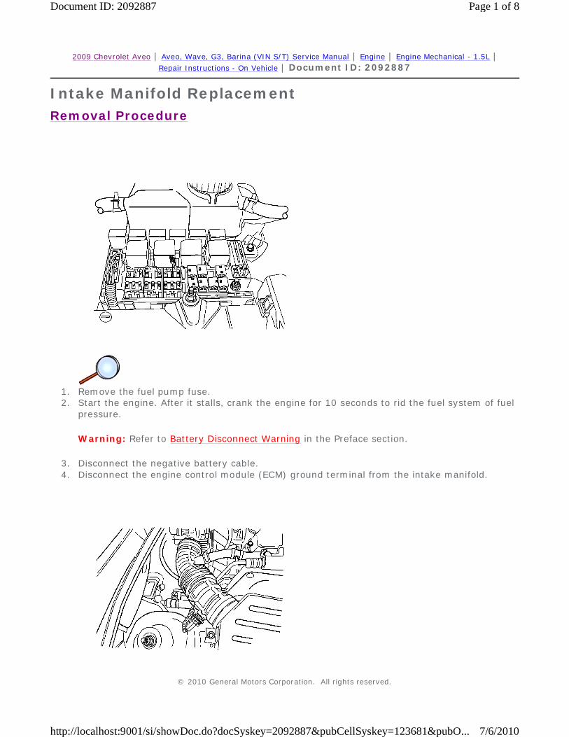
8. Install the fuel rail and the fuel injectors as an assembly. Refer to Fuel Injection Fuel Rail
Assembly Replacement. 9. Install the fuel rail retaining bolts.
Tighten Tighten the fuel rail retaining bolts to 25 N·m (18 lb ft).
10. Connect the fuel feed line to the fuel rail.
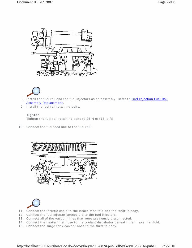
11. Connect the throttle cable to the intake manifold and the throttle body. 12. Connect the fuel injector connectors to the fuel injectors. 13. Connect all of the vacuum lines that were previously disconnected. 14. Connect the heater inlet hose to the coolant distributor beneath the intake manifold. 15. Connect the surge tank coolant hose to the throttle body.
Page 7 of 8Document ID: 2092887
7/6/2010http://localhost:9001/si/showDoc.do?docSyskey=2092887&pubCellSyskey=123681&pubO...

16. Connect the IAC valve connector. 17. Connect the throttle position sensor connector.
18. Connect the air intake tube to the throttle body. 19. Connect the IAT sensor connector. 20. Connect the ECM ground terminal to the intake manifold. 21. Connect the negative battery cable. 22. Install the fuel pump fuse. 23. Refill the engine cooling system. Refer to Cooling System Draining and Filling.
Page 8 of 8Document ID: 2092887
7/6/2010http://localhost:9001/si/showDoc.do?docSyskey=2092887&pubCellSyskey=123681&pubO...

2009 Chevrolet Aveo | Aveo, Wave, G3, Barina (VIN S/T) Service Manual | Engine | Engine Mechanical - 1.5L | Repair Instructions - On Vehicle | Document ID: 2092888
Timing Belt Replacement
Special Tools
Removal Procedure
Warning: Refer to Battery Disconnect Warning in the Preface section.
1. Disconnect the negative battery cable. 2. Disconnect the intake air temperature (IAT) sensor connector. 3. Disconnect the air intake tube from the throttle body. 4. Disconnect the breather tube from the valve cover.
• J 42492-A (KM 421-A) Timing Belt Adjuster
• KM-470-B Angular Torque Gage
• J 45059 Angle Meter
© 2010 General Motors Corporation. All rights reserved.
Page 1 of 10Document ID: 2092888
7/6/2010http://localhost:9001/si/showDoc.do?docSyskey=2092888&pubCellSyskey=123682&pubO...
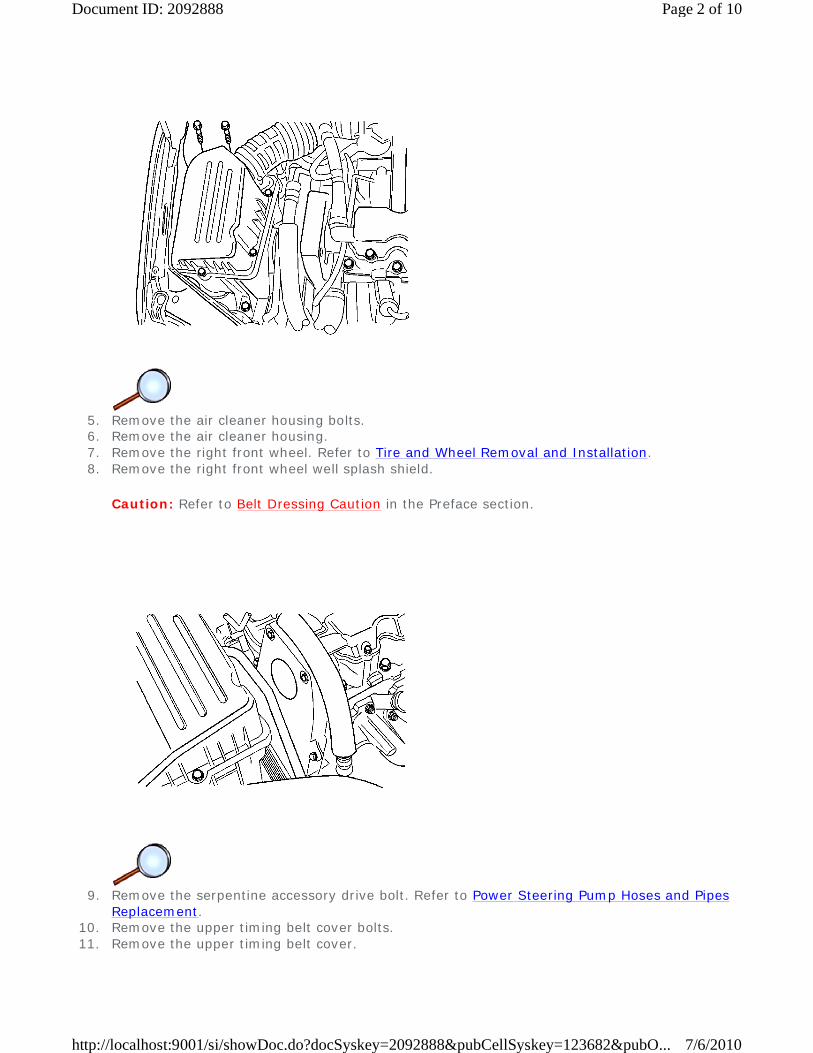
5. Remove the air cleaner housing bolts. 6. Remove the air cleaner housing. 7. Remove the right front wheel. Refer to Tire and Wheel Removal and Installation. 8. Remove the right front wheel well splash shield.
Caution: Refer to Belt Dressing Caution in the Preface section.
9. Remove the serpentine accessory drive bolt. Refer to Power Steering Pump Hoses and Pipes
Replacement. 10. Remove the upper timing belt cover bolts. 11. Remove the upper timing belt cover.
Page 2 of 10Document ID: 2092888
7/6/2010http://localhost:9001/si/showDoc.do?docSyskey=2092888&pubCellSyskey=123682&pubO...

12. Remove the crankshaft pulley bolt. 13. Remove the crankshaft pulley. 14. Remove the lower timing belt cover bolts. 15. Remove the lower timing belt cover.
16. Install the crankshaft pulley bolt. 17. Using the crankshaft pulley bolt, rotate the crankshaft clockwise until the mark on the
crankshaft gear is aligned with the notch at the bottom of the rear timing belt cover.
Page 3 of 10Document ID: 2092888
7/6/2010http://localhost:9001/si/showDoc.do?docSyskey=2092888&pubCellSyskey=123682&pubO...

18. Slightly loosen the coolant pump retaining bolts. 19. Using the J 42492-A (1), rotate the coolant pump counterclockwise to release the tension on
the timing belt. 20. Remove the engine mount bracket. Refer to Engine Mount Replacement. 21. Remove the timing belt.
Installation Procedure
1. Align the mark on the crankshaft gear to the notch on the bottom of the rear timing belt
cover. 2. Align the mark on the camshaft gear to the notch on the top of the rear timing belt cover. 3. Install the timing belt.
Page 4 of 10Document ID: 2092888
7/6/2010http://localhost:9001/si/showDoc.do?docSyskey=2092888&pubCellSyskey=123682&pubO...

4. Using the J 42492-A (1), rotate the coolant pump clockwise to add the highest tension to the
timing belt. 5. Tighten the coolant pump retaining bolts loosely.
6. Align the adjust arm hole of the timing belt automatic tensioner to the hole in the timing belt
automatic tensioner bracket. 7. Insert a 4.5 mm driver through the adjust arm hole and the tensioner bracket hole.
Page 5 of 10Document ID: 2092888
7/6/2010http://localhost:9001/si/showDoc.do?docSyskey=2092888&pubCellSyskey=123682&pubO...

8. Rotate the crankshaft 2 full turns clockwise using the crankshaft pulley bolt. 9. Align the mark on the crankshaft gear to the notch at the bottom of the rear timing belt
cover.
10. Remove the driver from the timing belt automatic tensioner. 11. Slightly loosen the 3 coolant pump retaining bolts. 12. Using the J 42492-A (1), rotate the coolant pump.
Page 6 of 10Document ID: 2092888
7/6/2010http://localhost:9001/si/showDoc.do?docSyskey=2092888&pubCellSyskey=123682&pubO...

13. Rotate the coolant pump until the adjust arm pointer of the timing belt automatic tensioner is
aligned with the notch in the timing belt automatic tensioner bracket.
Caution: Refer to Fastener Caution in the Preface section.
14. Tighten the coolant pump retaining bolts.
Tighten Tighten the coolant pump retaining bolts to 10 N·m (89 lb in).
15. Remove the crankshaft pulley bolt. 16. Install the lower timing belt cover.
Page 7 of 10Document ID: 2092888
7/6/2010http://localhost:9001/si/showDoc.do?docSyskey=2092888&pubCellSyskey=123682&pubO...

17. Install the lower timing belt cover bolts.
Tighten Tighten the lower timing belt cover bolts to 10 N·m (89 lb in).
18. Install the crankshaft pulley. 19. Install the crankshaft pulley bolt.
Tighten
• Tighten the crankshaft pulley bolt to 95 N·m (70 lb ft) using a torque wrench.
• Using the J 45059 or the KM-470-B , tighten the crankshaft pulley bolt another 30 degrees plus 15 degrees.
Page 8 of 10Document ID: 2092888
7/6/2010http://localhost:9001/si/showDoc.do?docSyskey=2092888&pubCellSyskey=123682&pubO...

20. Install the upper timing belt cover. 21. Install the upper timing belt cover bolts.
Tighten Tighten the upper timing belt cover bolts to 10 N·m (89 lb in).
Caution: Refer to Belt Dressing Caution in the Preface section.
22. Install the serpentine accessory drive belt.
Page 9 of 10Document ID: 2092888
7/6/2010http://localhost:9001/si/showDoc.do?docSyskey=2092888&pubCellSyskey=123682&pubO...

23. Install the right front wheel well splash shield. 24. Install the right front wheel. Refer to Tire and Wheel Removal and Installation. 25. Install the air filter housing. 26. Install the air filter housing bolts.
Tighten Tighten the air filter housing bolts to 12 N·m (106 lb in).
27. Connect the air intake tube to the throttle body. 28. Connect the breather tube to the valve cover. 29. Connect the IAT sensor connector. 30. Connect the negative battery cable.
Page 10 of 10Document ID: 2092888
7/6/2010http://localhost:9001/si/showDoc.do?docSyskey=2092888&pubCellSyskey=123682&pubO...

2009 Chevrolet Aveo | Aveo, Wave, G3, Barina (VIN S/T) Service Manual | Engine | Engine Mechanical - 1.5L | Repair Instructions - On Vehicle | Document ID: 2092891
Timing Belt Cover Replacement
Removal Procedure
Warning: Refer to Battery Disconnect Warning in the Preface section.
1. Disconnect the negative battery cable. 2. Remove the timing belt. Refer to Timing Belt Replacement.
Note: Take extreme care to prevent any scratches, nicks, or damage to the camshaft. Such damage can impair vehicle operation.
3. Remove the camshaft gear. Refer to Camshaft Replacement. 4. Remove the timing belt automatic tensioner bolt. 5. Remove the timing belt automatic tensioner. 6. Remove the rear timing belt cover bolts. 7. Remove the rear timing belt cover.
Installation Procedure
© 2010 General Motors Corporation. All rights reserved.
Page 1 of 2Document ID: 2092891
7/6/2010http://localhost:9001/si/showDoc.do?docSyskey=2092891&pubCellSyskey=127263&pubO...

1. Install the rear timing belt cover.
Caution: Refer to Fastener Caution in the Preface section.
2. Install the rear timing belt cover bolts and tighten to 10 N·m (89 lb in). 3. Install the timing belt automatic tensioner. 4. Install the timing belt automatic tensioner bolt and tighten to 20 N·m (15 lb ft).
Note: Take extreme care to prevent any scratches, nicks, or damage to the camshaft. Such damage can impair vehicle operation.
5. Install the camshaft gear. Refer to Camshaft Replacement. 6. Install the timing belt. Refer to Timing Belt Replacement. 7. Connect the negative battery cable.
Page 2 of 2Document ID: 2092891
7/6/2010http://localhost:9001/si/showDoc.do?docSyskey=2092891&pubCellSyskey=127263&pubO...

2009 Chevrolet Aveo | Aveo, Wave, G3, Barina (VIN S/T) Service Manual | Engine | Engine Mechanical - 1.5L | Repair Instructions - On Vehicle | Document ID: 2092892
Valve Rocker Arm Cover Replacement
Removal Procedure
Warning: Refer to Battery Disconnect Warning in the Preface section.
1. Disconnect the negative battery cable. 2. Disconnect the breather hose from the valve cover.
3. Remove the 8 bolts from the valve cover.
© 2010 General Motors Corporation. All rights reserved.
Page 1 of 3Document ID: 2092892
7/6/2010http://localhost:9001/si/showDoc.do?docSyskey=2092892&pubCellSyskey=127264&pubO...

4. Remove the valve cover. 5. Remove the valve cover gasket. 6. Clean the sealing surfaces of the valve cover and the camshaft housing.
Installation Procedure
1. Install the new valve cover gasket and the valve cover.
Caution: Refer to Fastener Caution in the Preface section.
2. Install the 8 bolts to the valve cover and tighten to 9 N·m (80 lb in).
3. Connect the breather tube to the valve cover.
Page 2 of 3Document ID: 2092892
7/6/2010http://localhost:9001/si/showDoc.do?docSyskey=2092892&pubCellSyskey=127264&pubO...

4. Connect the negative battery cable.
Page 3 of 3Document ID: 2092892
7/6/2010http://localhost:9001/si/showDoc.do?docSyskey=2092892&pubCellSyskey=127264&pubO...
2009 Chevrolet Aveo | Aveo, Wave, G3, Barina (VIN S/T) Service Manual | Engine | Engine Mechanical - 1.5L | Repair Instructions - On Vehicle | Document ID: 2092900
Oil Pan Replacement
Removal Procedure
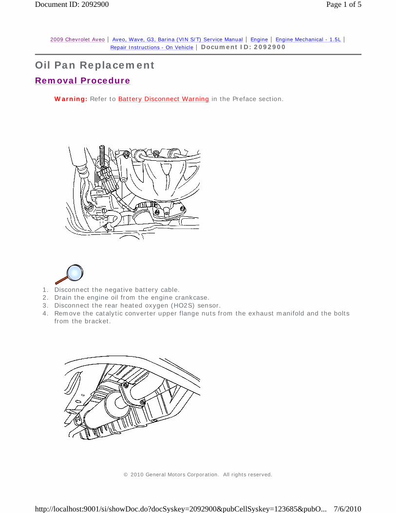
Warning: Refer to Battery Disconnect Warning in the Preface section.
1. Disconnect the negative battery cable. 2. Drain the engine oil from the engine crankcase. 3. Disconnect the rear heated oxygen (HO2S) sensor. 4. Remove the catalytic converter upper flange nuts from the exhaust manifold and the bolts
from the bracket.
© 2010 General Motors Corporation. All rights reserved.
Page 1 of 5Document ID: 2092900
7/6/2010http://localhost:9001/si/showDoc.do?docSyskey=2092900&pubCellSyskey=123685&pubO...

5. Remove the nuts from the front muffler pipe to the connecting pipe.
6. Remove the oil pan retaining bolts. 7. Remove the oil pan from the engine block.
Installation Procedure
1. Make sure that the oil pan and mounting surface on the engine block are free of all oil and
debris. 2. Install the oil pan gasket to the oil pan.
Page 2 of 5Document ID: 2092900
7/6/2010http://localhost:9001/si/showDoc.do?docSyskey=2092900&pubCellSyskey=123685&pubO...

Note: Install the oil pan within 5 minutes after applying liquid gasket to the oil pan.
3. Install the oil pan to the engine block.
Caution: Refer to Fastener Caution in the Preface section.
4. Install the oil pan retaining bolts.
Tighten Tighten the oil pan retaining bolts to 10 N·m (89 lb in).
5. Install the catalytic converters-to-exhaust manifold nuts.
Tighten Tighten the catalytic converter-to-exhaust manifold nuts and bracket bolts to 40 N·m (30 lb ft).
Page 3 of 5Document ID: 2092900
7/6/2010http://localhost:9001/si/showDoc.do?docSyskey=2092900&pubCellSyskey=123685&pubO...

6. Install the nuts from the front muffler pipe to the connecting pipe and catalytic converter.
Tighten Tighten the front muffler-to-connecting pipe nuts to 30 N·m (22 lb ft).
7. Connect the rear heated oxygen sensor connector.
8. Connect the negative battery cable. 9. Discard the used oil pan drain plug washer and replace it with a new one.
10. Install the oil pan drain plug.
Tighten Tighten the oil pan drain plug to 35 N·m (25 lb ft).
Page 4 of 5Document ID: 2092900
7/6/2010http://localhost:9001/si/showDoc.do?docSyskey=2092900&pubCellSyskey=123685&pubO...

11. Refill the engine crankcase with engine oil.
Page 5 of 5Document ID: 2092900
7/6/2010http://localhost:9001/si/showDoc.do?docSyskey=2092900&pubCellSyskey=123685&pubO...

2009 Chevrolet Aveo | Aveo, Wave, G3, Barina (VIN S/T) Service Manual | Engine | Engine Mechanical - 1.5L | Repair Instructions - On Vehicle | Document ID: 2092902
Oil Pump Replacement
Removal Procedure
Warning: Refer to Battery Disconnect Warning in the Preface section.
1. Disconnect the negative battery cable. 2. Remove the timing belt. Refer to Timing Belt Replacement. 3. Remove the rear timing belt cover. Refer to Timing Belt Cover Replacement. 4. Disconnect the oil pressure switch connector.
© 2010 General Motors Corporation. All rights reserved.
Page 1 of 5Document ID: 2092902
7/6/2010http://localhost:9001/si/showDoc.do?docSyskey=2092902&pubCellSyskey=123686&pubO...

5. Remove the crankshaft position (CKP) sensor bolt. 6. Remove the CKP sensor. 7. Remove the oil pan. Refer to Oil Pan Replacement. 8. Remove the oil pump pickup tube and the support bracket bolts. 9. Remove the oil pump pickup tube.
10. Remove the oil pump retaining bolts (1).
Warning: Refer to Safety Glasses Warning in the Preface section.
11. Carefully separate the oil pump and the gasket from the engine block and the oil pan. 12. Remove the oil pump.
Installation Procedure
Page 2 of 5Document ID: 2092902
7/6/2010http://localhost:9001/si/showDoc.do?docSyskey=2092902&pubCellSyskey=123686&pubO...
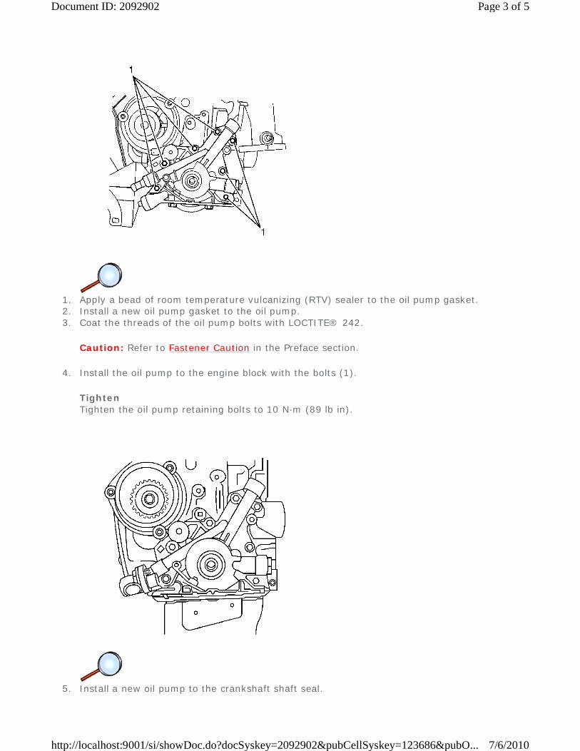
1. Apply a bead of room temperature vulcanizing (RTV) sealer to the oil pump gasket. 2. Install a new oil pump gasket to the oil pump. 3. Coat the threads of the oil pump bolts with LOCTITE® 242.
Caution: Refer to Fastener Caution in the Preface section.
4. Install the oil pump to the engine block with the bolts (1).
Tighten Tighten the oil pump retaining bolts to 10 N·m (89 lb in).
5. Install a new oil pump to the crankshaft shaft seal.
Page 3 of 5Document ID: 2092902
7/6/2010http://localhost:9001/si/showDoc.do?docSyskey=2092902&pubCellSyskey=123686&pubO...

6. Coat the lip of the seal with a thin coat of grease.
7. Coat the threads of the oil pump pickup tube and the support bracket bolts with
LOCTITE® 242. 8. Install the oil pump pickup tube and the bolts.
Tighten Tighten the oil pump pickup tube and the support bracket bolts to 10 N·m (89 lb in).
9. Install the oil pan. Refer to Oil Pan Replacement.
10. Install the CKP sensor and the bolt.
Tighten
Page 4 of 5Document ID: 2092902
7/6/2010http://localhost:9001/si/showDoc.do?docSyskey=2092902&pubCellSyskey=123686&pubO...

Tighten the crankshaft position sensor retaining bolt to 10 N·m (89 lb in).
11. Connect the oil pressure switch connector. 12. Install the rear timing belt cover. Refer to Timing Belt Cover Replacement. 13. Install the timing belt. Refer to Timing Belt Replacement. 14. Connect the negative battery cable.
Page 5 of 5Document ID: 2092902
7/6/2010http://localhost:9001/si/showDoc.do?docSyskey=2092902&pubCellSyskey=123686&pubO...

2009 Chevrolet Aveo | Aveo, Wave, G3, Barina (VIN S/T) Service Manual | Engine | Engine Mechanical - 1.5L | Repair Instructions - On Vehicle | Document ID: 2092904
Engine Mount Replacement
Special Tools
J 28467-B (DW 117) Universal Engine Assembly Support Fixture
Removal Procedure
Warning: Refer to Battery Disconnect Warning in the Preface section.
Caution: Refer to Engine Mounting Caution in the Preface section.
1. Disconnect the negative battery cable. 2. Remove the air cleaner housing bolts and the air filter housing assembly.
Caution: When raising or supporting the engine for any reason, do not use a jack under the oil pan, any sheet metal, or crankshaft balancer. Jacking against the oil pan may cause it to crack or break.
3. Support the engine assembly using the J 28467-B .
© 2010 General Motors Corporation. All rights reserved.
Page 1 of 4Document ID: 2092904
7/6/2010http://localhost:9001/si/showDoc.do?docSyskey=2092904&pubCellSyskey=127267&pubO...

4. Remove the engine mount bracket retaining bolts (1).
5. Remove the engine mount attaching nuts (1). 6. Remove the engine mount.
Installation Procedure
Page 2 of 4Document ID: 2092904
7/6/2010http://localhost:9001/si/showDoc.do?docSyskey=2092904&pubCellSyskey=127267&pubO...

1. Install the engine mount.
Caution: Refer to Fastener Caution in the Preface section.
2. Install the engine mount attaching nuts (1).
Tighten Tighten the engine mount attaching nuts to 40 N·m (30 lb ft).
3. Install the engine mount bracket retaining bolts (1).
Tighten
Page 3 of 4Document ID: 2092904
7/6/2010http://localhost:9001/si/showDoc.do?docSyskey=2092904&pubCellSyskey=127267&pubO...
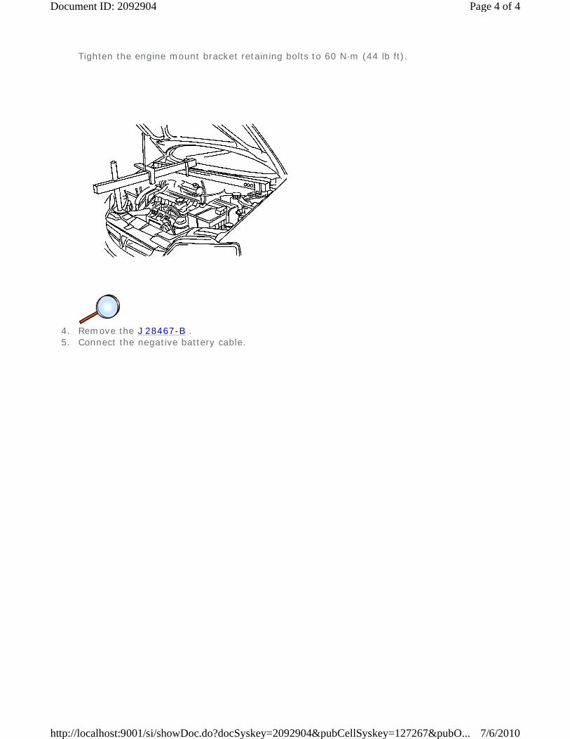
Tighten the engine mount bracket retaining bolts to 60 N·m (44 lb ft).
4. Remove the J 28467-B . 5. Connect the negative battery cable.
Page 4 of 4Document ID: 2092904
7/6/2010http://localhost:9001/si/showDoc.do?docSyskey=2092904&pubCellSyskey=127267&pubO...
2009 Chevrolet Aveo | Aveo, Wave, G3, Barina (VIN S/T) Service Manual | Engine | Engine Mechanical - 1.5L | Repair Instructions - On Vehicle | Document ID: 2092905
Engine Replacement
Special Tools
Removal Procedure
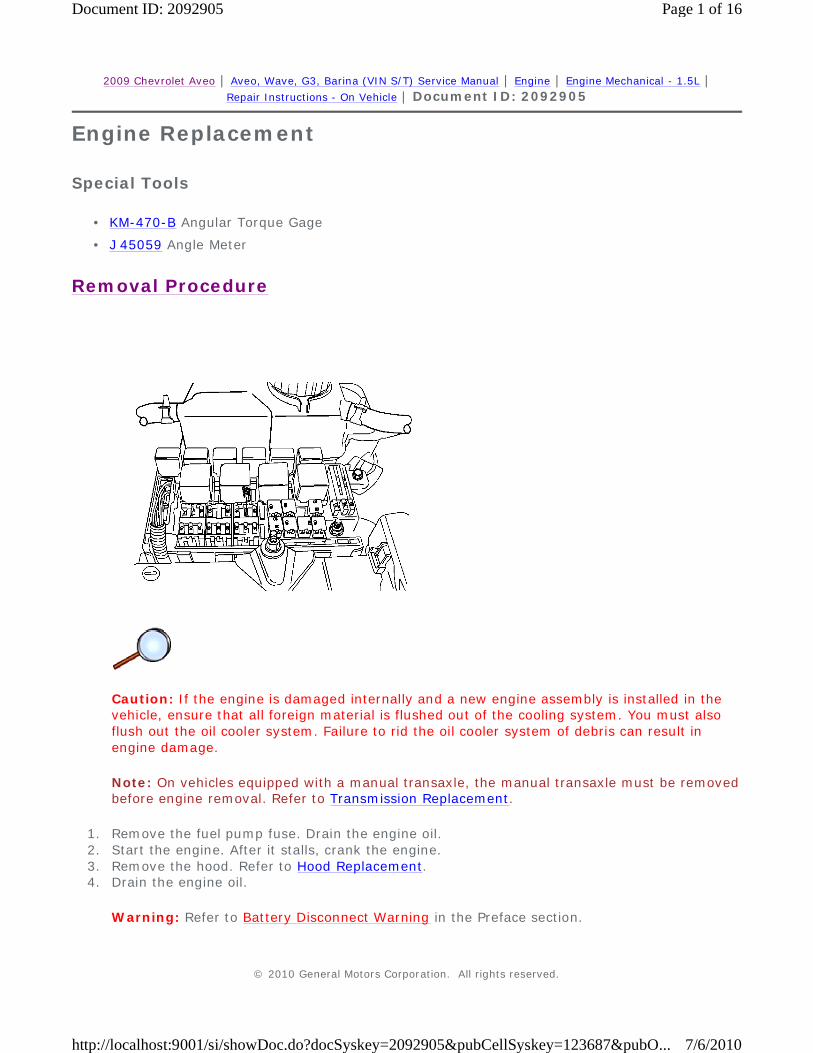
Caution: If the engine is damaged internally and a new engine assembly is installed in the vehicle, ensure that all foreign material is flushed out of the cooling system. You must also flush out the oil cooler system. Failure to rid the oil cooler system of debris can result in engine damage.
Note: On vehicles equipped with a manual transaxle, the manual transaxle must be removed before engine removal. Refer to Transmission Replacement.
1. Remove the fuel pump fuse. Drain the engine oil. 2. Start the engine. After it stalls, crank the engine. 3. Remove the hood. Refer to Hood Replacement. 4. Drain the engine oil.
Warning: Refer to Battery Disconnect Warning in the Preface section.
• KM-470-B Angular Torque Gage
• J 45059 Angle Meter
© 2010 General Motors Corporation. All rights reserved.
Page 1 of 16Document ID: 2092905
7/6/2010http://localhost:9001/si/showDoc.do?docSyskey=2092905&pubCellSyskey=123687&pubO...

5. Disconnect the negative battery cable. 6. Disconnect and separate the battery positive cable. 7. Disconnect the negative battery cable from the vehicle frame.
8. Discharge the air conditioning (A/C) system, if equipped. Refer to Refrigerant Recovery and
Recharging. 9. Disconnect the intake air temperature (IAT) sensor connector.
10. Remove the air intake tube from the throttle body and the air filter housing. 11. Disconnect the breather tube from the valve cover.
Page 2 of 16Document ID: 2092905
7/6/2010http://localhost:9001/si/showDoc.do?docSyskey=2092905&pubCellSyskey=123687&pubO...

12. Remove the right front wheel. Refer to Tire and Wheel Removal and Installation. 13. Remove the right front wheel well splash shield. 14. Remove the serpentine accessory drive belt.
15. Drain the engine coolant. Refer to Cooling System Draining and Filling. 16. Remove the cooling system radiator and the engine cooling fans. Refer to Radiator
Replacement and Engine Coolant Fan Replacement. 17. Disconnect the upper radiator hose from the thermostat housing. 18. Disconnect the coolant surge tank hose from the radiator. 19. Disconnect the power steering return hose from the power steering pump, if equipped. 20. Drain the power steering system, if equipped. 21. Disconnect the power steering pressure hose from the power steering pump, if equipped.
Page 3 of 16Document ID: 2092905
7/6/2010http://localhost:9001/si/showDoc.do?docSyskey=2092905&pubCellSyskey=123687&pubO...

22. Disconnect the electrical connector at the electronic ignition (EI) system ignition coil, and the
engine control module (ECM) ground terminal at the intake manifold and at the starter motor.
23. Disconnect the pre-converter oxygen (O2) sensor connector. 24. Disconnect the electrical connectors at the fuel injectors. 25. Disconnect the idle air control (IAC) valve connector. 26. Disconnect the throttle position (TP) sensor connector. 27. Disconnect the engine coolant temperature (ECT) sensor connector and the knock sensor, if
equipped.
28. Disconnect the alternator voltage regulator connector. 29. Disconnect all of the necessary vacuum lines, including the brake booster vacuum hose. 30. Disconnect the fuel feed line at the fuel rail. 31. Disconnect the throttle cable from the throttle body and the intake manifold bracket. 32. Disconnect the camshaft position (CMP) sensor connector.
Page 4 of 16Document ID: 2092905
7/6/2010http://localhost:9001/si/showDoc.do?docSyskey=2092905&pubCellSyskey=123687&pubO...

33. Disconnect the surge tank coolant hose at the throttle body. 34. Disconnect the heater inlet hose from the coolant distributor. 35. Disconnect the heater outlet hose at the coolant pipe. 36. Disconnect the surge tank coolant hose from the coolant pipe. 37. Disconnect the lower radiator hose at the coolant pipe.
38. Disconnect the starter solenoid S terminal wire. 39. Remove the A/C compressor hose assembly retaining bolt. 40. Disconnect the A/C compressor hose assembly from the compressor. 41. Disconnect the A/C compressor coil connector. 42. Remove the A/C compressor mounting bolts. 43. Remove the A/C compressor. 44. Remove the A/C compressor mounting bracket bolts. 45. Remove the A/C compressor mounting bracket from the engine block.
Page 5 of 16Document ID: 2092905
7/6/2010http://localhost:9001/si/showDoc.do?docSyskey=2092905&pubCellSyskey=123687&pubO...

46. Remove the catalytic converter nuts from the exhaust manifold.
47. Remove the nuts from the front muffler pipe to the connecting pipe.
Page 6 of 16Document ID: 2092905
7/6/2010http://localhost:9001/si/showDoc.do?docSyskey=2092905&pubCellSyskey=123687&pubO...

48. Remove the engine crankshaft pulley bolt. 49. Remove the engine crankshaft pulley.
50. Disconnect the vacuum lines at the evaporative (EVAP) emission canister purge. 51. Disconnect the electrical connector at the EVAP emission canister purge solenoid and the
knock sensor. 52. Disconnect the electrical connector at the oil pressure switch. 53. Disconnect the crankshaft position (CKP) sensor connector and the CMP sensor connector. 54. Remove the CKP sensor retaining bolt. 55. Remove the CKP sensor.
Page 7 of 16Document ID: 2092905
7/6/2010http://localhost:9001/si/showDoc.do?docSyskey=2092905&pubCellSyskey=123687&pubO...

56. Remove the battery. 57. Remove the battery tray. 58. Remove the right transaxle brace bolts from the transaxle. 59. Disconnect the back up switch connector. 60. Remove the hydraulic clutch pipe.
61. Remove the transaxle bell housing bolts.
Caution: Refer to Engine Lifting Caution in the Preface section.
62. Support the transaxle with a floor jack. 63. Install the engine lifting device. 64. Disconnect the right engine mount bracket from the rubber engine mount by removing the
retaining bolts (1).
Page 8 of 16Document ID: 2092905
7/6/2010http://localhost:9001/si/showDoc.do?docSyskey=2092905&pubCellSyskey=123687&pubO...

65. Remove the right engine mount bracket from the engine block. 66. Separate the engine block from the transaxle. 67. Remove the engine. 68. Transfer any necessary parts.
Installation Procedure
1. Install the engine into the engine compartment. 2. Align the transaxle alignment pins (1) to the transaxle.
Caution: Refer to Fastener Caution in the Preface section.
3. Install the transaxle bell housing bolts.
Tighten Tighten the transaxle bell housing bolts to 75 N·m (55 lb ft).
Page 9 of 16Document ID: 2092905
7/6/2010http://localhost:9001/si/showDoc.do?docSyskey=2092905&pubCellSyskey=123687&pubO...

4. Install the right engine mount bracket to the engine block. 5. Install the right engine mount bracket retaining bolts (1) to the engine block.
Tighten Tighten the engine mount bracket retaining bolts to 60 N·m (44 lb ft).
6. Install the engine mount-to-bracket retaining bolts.
Tighten Tighten the engine mount bracket-to-engine mount retaining bolts to 60 N·m (44 lb ft).
7. Remove the floor jack used for support of the transaxle. 8. Remove the engine lifting device.
Page 10 of 16Document ID: 2092905
7/6/2010http://localhost:9001/si/showDoc.do?docSyskey=2092905&pubCellSyskey=123687&pubO...

9. Install the right transaxle brace bolts to the transaxle.
Tighten Tighten the right transaxle brace bolts to 60 N·m (44 lb ft).
10. Connect the back up switch electrical connector. 11. Install the hydraulic clutch pipe. 12. Install the battery tray. 13. Install the battery with the nut. 14. Connect the vacuum lines at the EVAP emission canister purge solenoid. 15. Connect the electrical connectors at the EVAP emission canister purge solenoid.
16. Connect the oil pressure switch connector. 17. Install the crankshaft pulley. 18. Install the crankshaft pulley bolt.
Tighten
• Tighten the crankshaft pulley bolt to 95 N·m (70 lb ft) using a torque wrench.
• Using the J 45059 or the KM-470-B , tighten the crankshaft pulley bolt another 30 degrees plus 15 degrees.
Page 11 of 16Document ID: 2092905
7/6/2010http://localhost:9001/si/showDoc.do?docSyskey=2092905&pubCellSyskey=123687&pubO...

19. Install the CKP sensor and the CKP sensor retaining bolt.
Tighten Tighten the crankshaft position sensor retaining bolt to 10 N·m (89 lb in).
20. Connect the CKP sensor connector. 21. Install the nuts from the front muffler pipe to the connecting pipe.
Tighten Tighten the front muffler pipe to the connecting pipe to 30 N·m (22 lb ft).
22. Install the nuts from the front muffler pipe to the catalytic converter.
Page 12 of 16Document ID: 2092905
7/6/2010http://localhost:9001/si/showDoc.do?docSyskey=2092905&pubCellSyskey=123687&pubO...
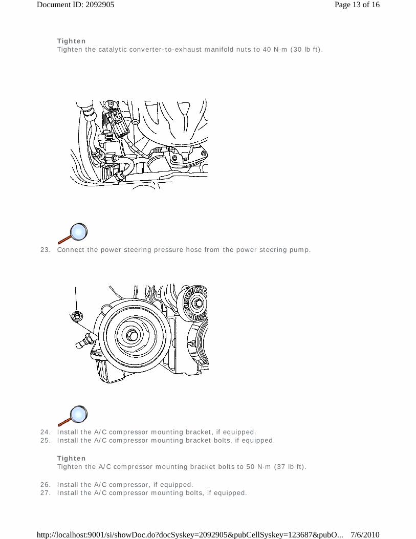
Tighten Tighten the catalytic converter-to-exhaust manifold nuts to 40 N·m (30 lb ft).
23. Connect the power steering pressure hose from the power steering pump.
24. Install the A/C compressor mounting bracket, if equipped. 25. Install the A/C compressor mounting bracket bolts, if equipped.
Tighten Tighten the A/C compressor mounting bracket bolts to 50 N·m (37 lb ft).
26. Install the A/C compressor, if equipped. 27. Install the A/C compressor mounting bolts, if equipped.
Page 13 of 16Document ID: 2092905
7/6/2010http://localhost:9001/si/showDoc.do?docSyskey=2092905&pubCellSyskey=123687&pubO...

Tighten Tighten the A/C compressor mounting bolts to 35 N·m (26 lb ft).
28. Connect the A/C compressor coil connector. 29. Install the serpentine accessory drive belt. 30. Connect the A/C compressor hose assembly and the A/C compressor hose assembly retaining
bolt, if equipped.
Tighten Tighten the A/C compressor hose assembly retaining bolt to 33 N·m (24 lb ft).
31. Install the right front wheel well splash shield. 32. Install the right front wheel. Refer to Tire and Wheel Removal and Installation. 33. Connect the fuel feed line to the fuel rail. 34. Connect all of the necessary vacuum lines, including the brake booster vacuum hose.
Page 14 of 16Document ID: 2092905
7/6/2010http://localhost:9001/si/showDoc.do?docSyskey=2092905&pubCellSyskey=123687&pubO...

35. Connect the pre-converter O2 sensor connector. 36. Connect the starter solenoid S terminal wire. 37. Connect the alternator voltage regulator connector. 38. Connect the ECT sensor connector. 39. Connect the TP sensor connector. 40. Connect the IAC valve connector. 41. Connect the CMP sensor connector.
42. Connect the electrical connectors at the fuel injectors. 43. Connect the electrical connector at the EI system ignition coil and the powertrain control
module (PCM)/ECM ground terminal at the intake manifold. 44. Install the air intake tube between the throttle body and the air filter housing. 45. Connect the breather tube to the valve cover. 46. Connect the IAT sensor connector.
Page 15 of 16Document ID: 2092905
7/6/2010http://localhost:9001/si/showDoc.do?docSyskey=2092905&pubCellSyskey=123687&pubO...

47. Install the cooling system radiator and the engine cooling fans. Refer to Radiator
Replacement. 48. Connect the lower radiator hose to the coolant pipe. 49. Connect the upper radiator hose to the thermostat housing. 50. Connect the coolant surge tank hose to the radiator. 51. Connect the heater outlet hose to the coolant pipe. 52. Connect the heater inlet hose to the coolant distributor. 53. Connect the coolant surge tank hose to the coolant pipe. 54. Connect the surge tank coolant hose to the throttle body.
55. Connect the throttle cable to the throttle body and the intake manifold bracket. Install the
fuel pump fuse. 56. Connect the negative battery cable to the vehicle frame. 57. Connect the negative battery cable to the battery. 58. Connect and assemble the battery positive cable. 59. Refill the engine crankcase with engine oil. 60. Refill the engine coolant system. Refer to Cooling System Draining and Filling. 61. Refill the engine coolant system. Refer to Checking and Adding Power Steering Fluid. 62. Bleed the power steering system as necessary. Refer to Power Steering System Bleeding. 63. Refill the A/C refrigerant system as necessary. Refer to Refrigerant Recovery and Recharging. 64. Install the hood. Refer to Hood Replacement.
Page 16 of 16Document ID: 2092905
7/6/2010http://localhost:9001/si/showDoc.do?docSyskey=2092905&pubCellSyskey=123687&pubO...

2009 Chevrolet Aveo | Aveo, Wave, G3, Barina (VIN S/T) Service Manual | Engine | Engine Mechanical - 1.5L | Repair Instructions - On Vehicle | Document ID: 2092906
Engine Oil and Oil Filter Replacement
Removal Procedure
1. Raise and properly support the vehicle. Refer to Lifting and Jacking the Vehicle. 2. Position an appropriate drain pan under the engine. 3. Remove the oil pan drain plug bolt. 4. Remove the oil filter.
Installation Procedure
Caution: Refer to Fastener Caution in the Preface section.
1. Install the oil filter and tighten to 14 N·m (10 lb ft). 2. Discard the used oil pan drain plug washer and replace with a new oil pan drain plug washer. 3. Install the oil pan drain plug bolt and tighten to 35 N·m (26 lb ft). 4. Lower the vehicle. 5. Fill the engine with oil to the appropriate mark. 6. Start engine and inspect for leaks.
© 2010 General Motors Corporation. All rights reserved.
Page 1 of 1Document ID: 2092906
7/6/2010http://localhost:9001/si/showDoc.do?docSyskey=2092906&pubCellSyskey=145596&pubO...

2009 Chevrolet Aveo | Aveo, Wave, G3, Barina (VIN S/T) Service Manual | Engine | Engine Mechanical - 1.5L | Repair Instructions - On Vehicle | Document ID: 2092932
Piston, Connecting Rod, and Bearing Replacement
Special Tools
Removal Procedure
Warning: Refer to Safety Glasses Warning in the Preface section.
1. Remove the cylinder head with the intake manifold and exhaust manifold attached. Refer to
Cylinder Head Replacement. 2. Remove the oil pan. Refer to Oil Pan Replacement. 3. Remove the oil pump/pickup tube bolts. 4. Remove the oil pump/pickup tube.
• KM-470-B Angular Torque Gage
• J 24086-B (KM-427) Piston Pin Remover/Installer
• J 45059 Angle Meter
© 2010 General Motors Corporation. All rights reserved.
Page 1 of 7Document ID: 2092932
7/6/2010http://localhost:9001/si/showDoc.do?docSyskey=2092932&pubCellSyskey=128173&pubO...

5. Move the piston to the bottom of the piston stroke. 6. Mark the connecting rod cap. 7. Remove the connecting rod cap bolts. 8. Remove the connecting rod cap and lower connecting rod bearing. 9. Remove the upper piston connecting rod bearing.
10. Ridge ream the cylinder wall.
Warning: Handle the piston carefully. Worn piston rings are sharp and may cause bodily injury.
11. Remove the piston. 12. Use a piston ring expander tool to expand the piston rings. 13. Remove the piston rings.
Page 2 of 7Document ID: 2092932
7/6/2010http://localhost:9001/si/showDoc.do?docSyskey=2092932&pubCellSyskey=128173&pubO...

14. Remove the piston pin from the piston and connecting rod assembly using the J 24086-B
(1). 15. Separate the piston from the connecting rod.
Installation Procedure
Warning: Avoid contact with moving parts and hot surfaces while working around a running engine in order to prevent physical injury.
1. Align the notch on the piston and connecting rod so that the proper sides will be facing the front of the engine.
Page 3 of 7Document ID: 2092932
7/6/2010http://localhost:9001/si/showDoc.do?docSyskey=2092932&pubCellSyskey=128173&pubO...

2. Install the piston pin guide through the piston and the connecting rod. 3. Coat the piston pin with clean oil. 4. Install the piston pin into the opposite side of the piston. 5. Install the piston pin into the piston and connecting rod assembly using the J 24086-B (1).
6. Select a set of new piston rings. 7. Measure the piston ring gap using a feeler gage. Refer to Engine Mechanical Specifications. 8. Increase the piston ring gap by carefully filing off excess material if the piston ring gap is
below specifications.
9. Measure the piston ring side clearance using a feeler gage. Refer to Engine Mechanical
Specifications. 10. If the piston ring is too thick, try another piston ring. 11. If no piston ring can be found that fits to specifications, the piston ring may be ground to size
with emery paper placed on a sheet of glass.
Page 4 of 7Document ID: 2092932
7/6/2010http://localhost:9001/si/showDoc.do?docSyskey=2092932&pubCellSyskey=128173&pubO...
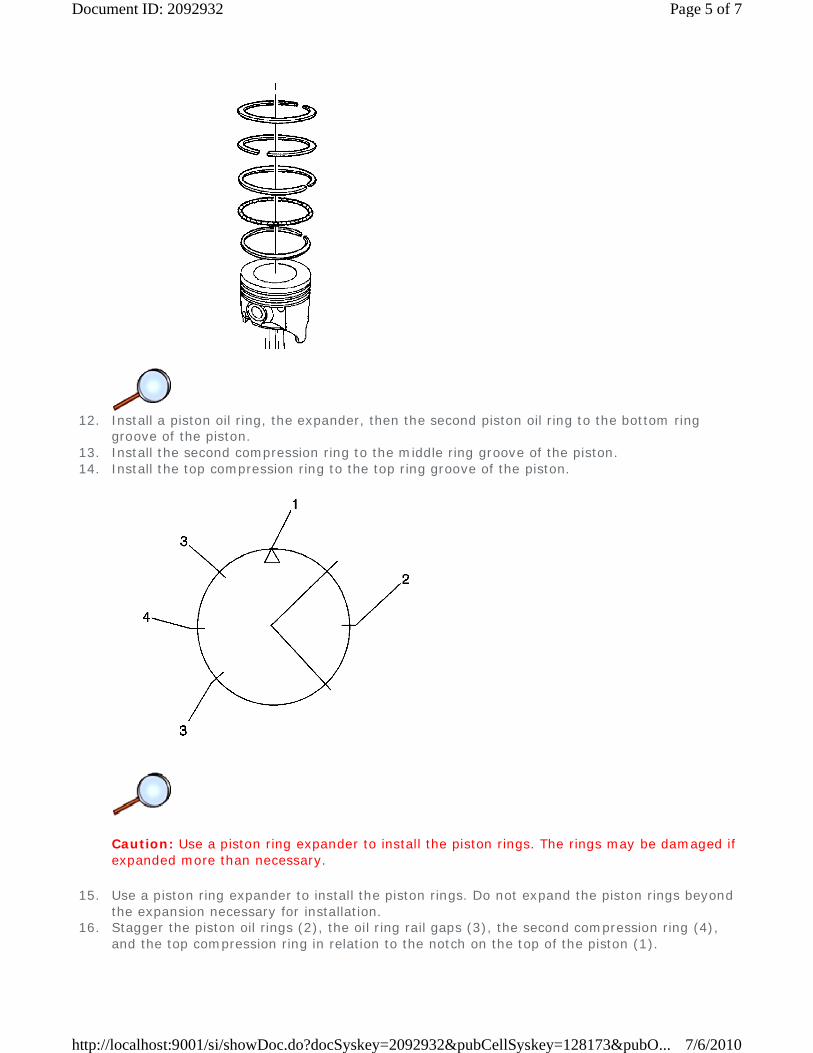
12. Install a piston oil ring, the expander, then the second piston oil ring to the bottom ring
groove of the piston. 13. Install the second compression ring to the middle ring groove of the piston. 14. Install the top compression ring to the top ring groove of the piston.
Caution: Use a piston ring expander to install the piston rings. The rings may be damaged if expanded more than necessary.
15. Use a piston ring expander to install the piston rings. Do not expand the piston rings beyond the expansion necessary for installation.
16. Stagger the piston oil rings (2), the oil ring rail gaps (3), the second compression ring (4), and the top compression ring in relation to the notch on the top of the piston (1).
Page 5 of 7Document ID: 2092932
7/6/2010http://localhost:9001/si/showDoc.do?docSyskey=2092932&pubCellSyskey=128173&pubO...
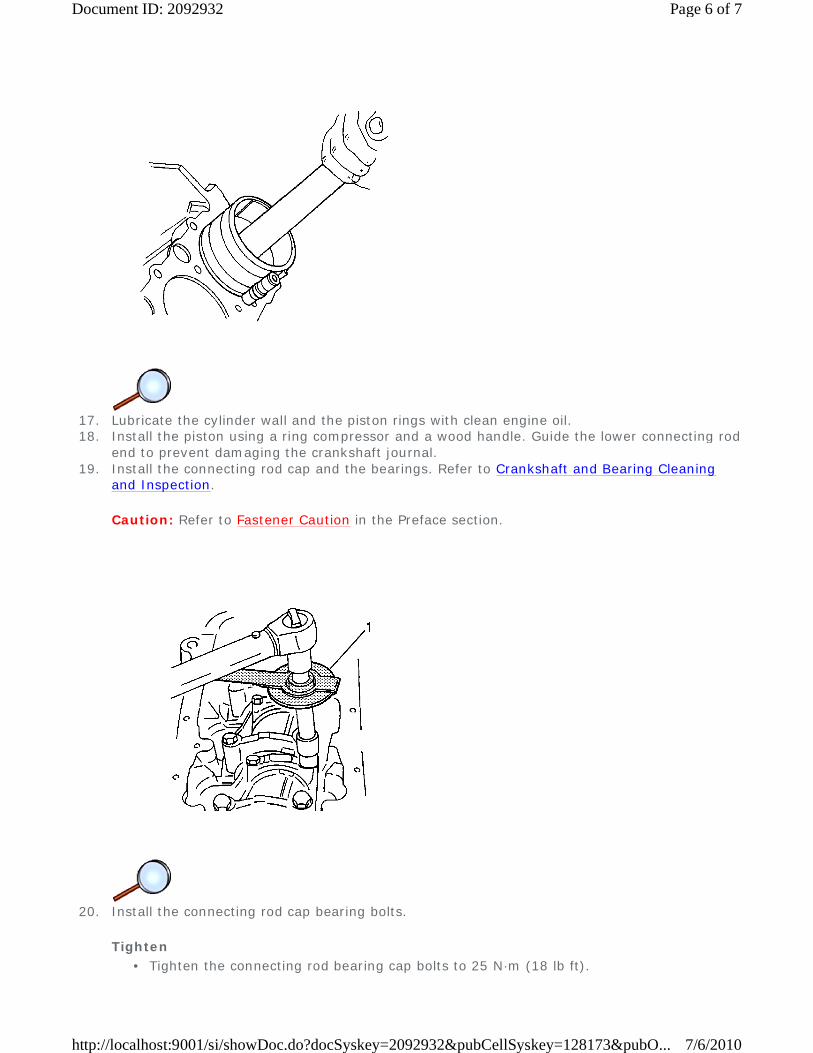
17. Lubricate the cylinder wall and the piston rings with clean engine oil. 18. Install the piston using a ring compressor and a wood handle. Guide the lower connecting rod
end to prevent damaging the crankshaft journal. 19. Install the connecting rod cap and the bearings. Refer to Crankshaft and Bearing Cleaning
and Inspection.
Caution: Refer to Fastener Caution in the Preface section.
20. Install the connecting rod cap bearing bolts.
Tighten
• Tighten the connecting rod bearing cap bolts to 25 N·m (18 lb ft).
Page 6 of 7Document ID: 2092932
7/6/2010http://localhost:9001/si/showDoc.do?docSyskey=2092932&pubCellSyskey=128173&pubO...
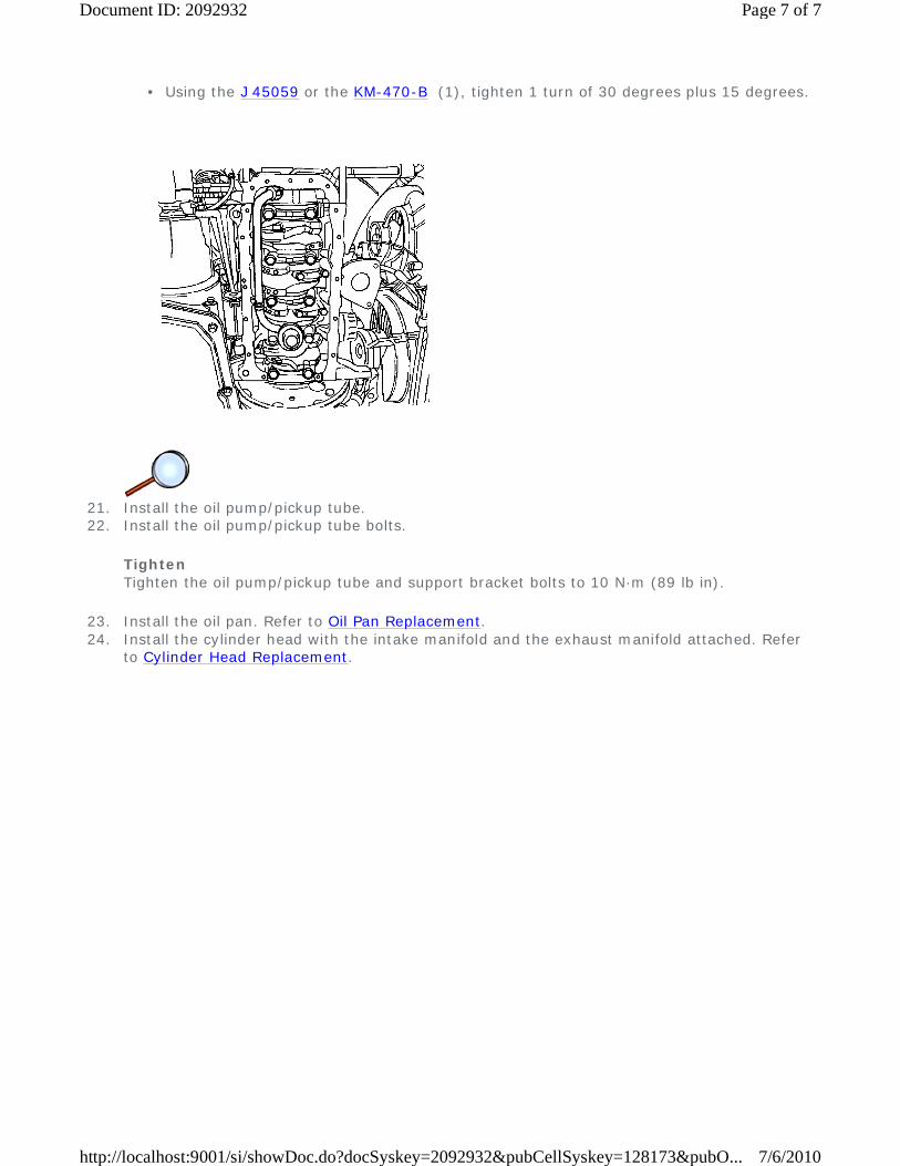
21. Install the oil pump/pickup tube. 22. Install the oil pump/pickup tube bolts.
Tighten Tighten the oil pump/pickup tube and support bracket bolts to 10 N·m (89 lb in).
23. Install the oil pan. Refer to Oil Pan Replacement. 24. Install the cylinder head with the intake manifold and the exhaust manifold attached. Refer
to Cylinder Head Replacement.
• Using the J 45059 or the KM-470-B (1), tighten 1 turn of 30 degrees plus 15 degrees.
Page 7 of 7Document ID: 2092932
7/6/2010http://localhost:9001/si/showDoc.do?docSyskey=2092932&pubCellSyskey=128173&pubO...

2009 Chevrolet Aveo | Aveo, Wave, G3, Barina (VIN S/T) Service Manual | Engine | Engine Mechanical - 1.5L | Repair Instructions - On Vehicle | Document ID: 2092940
Camshaft Gear Replacement
Removal Procedure
Warning: Refer to Battery Disconnect Warning in the Preface section.
1. Disconnect the negative battery cable. 2. Remove the timing belt. Refer to Timing Belt Replacement. 3. Remove the valve cover bolts. 4. Remove the valve cover.
Warning: Refer to Safety Glasses Warning in the Preface section.
© 2010 General Motors Corporation. All rights reserved.
Page 1 of 3Document ID: 2092940
7/6/2010http://localhost:9001/si/showDoc.do?docSyskey=2092940&pubCellSyskey=127268&pubO...
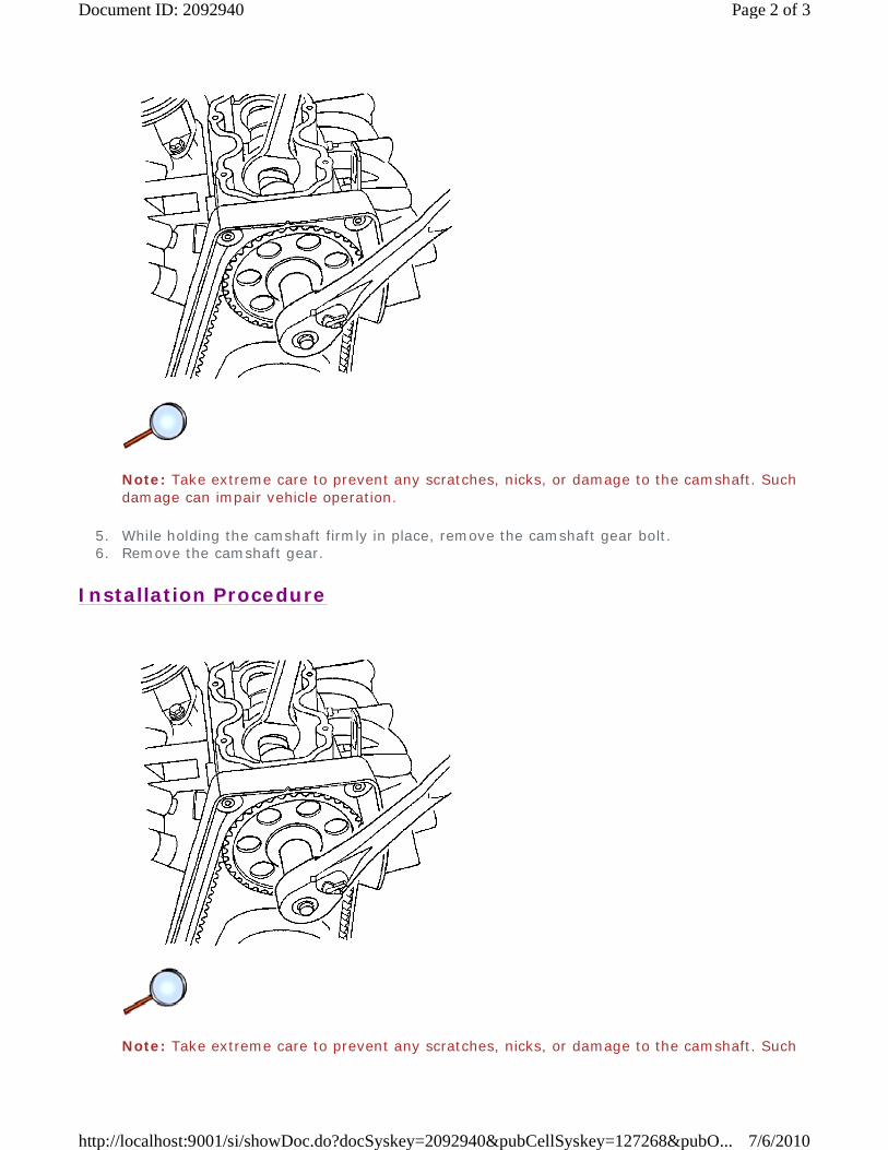
Note: Take extreme care to prevent any scratches, nicks, or damage to the camshaft. Such damage can impair vehicle operation.
5. While holding the camshaft firmly in place, remove the camshaft gear bolt. 6. Remove the camshaft gear.
Installation Procedure
Note: Take extreme care to prevent any scratches, nicks, or damage to the camshaft. Such
Page 2 of 3Document ID: 2092940
7/6/2010http://localhost:9001/si/showDoc.do?docSyskey=2092940&pubCellSyskey=127268&pubO...

damage can impair vehicle operation.
1. Install the camshaft gear.
Caution: Refer to Fastener Caution in the Preface section.
2. While holding the camshaft firmly in place, install the camshaft gear bolt.
Tighten Tighten the camshaft gear bolt to 45 N·m (33 lb ft).
3. Install the valve cover. 4. Install the valve cover bolts.
Tighten Tighten the valve cover bolts to 9 N·m (80 lb in).
5. Install the timing belt. Refer to Timing Belt Replacement. 6. Connect the negative battery cable.
Page 3 of 3Document ID: 2092940
7/6/2010http://localhost:9001/si/showDoc.do?docSyskey=2092940&pubCellSyskey=127268&pubO...

2009 Chevrolet Aveo | Aveo, Wave, G3, Barina (VIN S/T) Service Manual | Engine | Engine Mechanical - 1.5L | Repair Instructions - On Vehicle | Document ID: 2092948
Camshaft Replacement
Special Tools
KM-565-A Valve Spring Compressor
Removal Procedure
1. Remove the timing belt. Refer to Timing Belt Replacement. 2. Disconnect the air breather tube at the valve cover. 3. Remove the valve cover bolts. 4. Remove the valve cover. 5. Remove the valve cover gasket.
© 2010 General Motors Corporation. All rights reserved.
Page 1 of 9Document ID: 2092948
7/6/2010http://localhost:9001/si/showDoc.do?docSyskey=2092948&pubCellSyskey=127269&pubO...

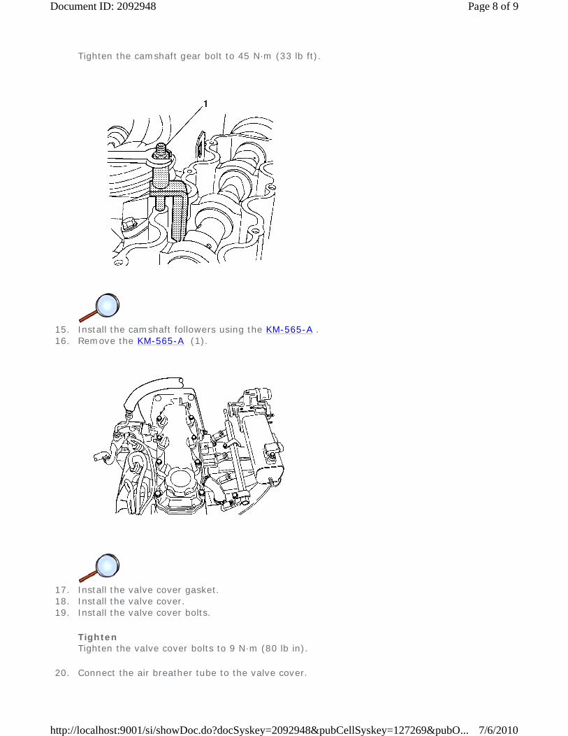
6. Install the KM-565-A .
Note: Take extreme care to prevent any scratches, nicks, or damage to the camshaft. Such damage can impair vehicle operation.
7. Remove the roller followers using the KM-565-A (1).
8. While holding the camshaft firmly in place, remove the camshaft gear bolt. 9. Remove the camshaft gear.
Page 2 of 9Document ID: 2092948
7/6/2010http://localhost:9001/si/showDoc.do?docSyskey=2092948&pubCellSyskey=127269&pubO...

10. Disconnect the positive battery cable from the battery. 11. Remove the battery and the battery tray. Refer to Battery Tray Replacement.
12. Disconnect the electronic ignition (EI) system ignition coil connector. 13. Disconnect the EI system ignition wires at the ignition coil. 14. Remove the EI system ignition coil mounting nuts. 15. Remove the EI system ignition coil.
Page 3 of 9Document ID: 2092948
7/6/2010http://localhost:9001/si/showDoc.do?docSyskey=2092948&pubCellSyskey=127269&pubO...

16. Remove the EI system ignition coil mounting plate bolts. 17. Remove the EI system ignition coil mounting plate.
18. Remove the camshaft pressure plate bolts. 19. Remove the camshaft pressure plate.
Page 4 of 9Document ID: 2092948
7/6/2010http://localhost:9001/si/showDoc.do?docSyskey=2092948&pubCellSyskey=127269&pubO...

20. Remove the camshaft.
Installation Procedure
1. Install the camshaft. 2. Install the camshaft pressure plate.
Caution: Refer to Fastener Caution in the Preface section.
3. Install the camshaft pressure plate bolts.
Page 5 of 9Document ID: 2092948
7/6/2010http://localhost:9001/si/showDoc.do?docSyskey=2092948&pubCellSyskey=127269&pubO...

Tighten Tighten the camshaft pressure plate bolts to 10 N·m (89 lb in).
4. Measure camshaft end play. Camshaft end play should be 0.09-0.21 mm (0.0035-0.0083 in).
5. Install the EI system ignition coil mounting plate. 6. Install the EI system ignition coil mounting plate bolts.
Tighten Tighten the EI system ignition coil mounting plate bolts to 10 N·m (89 lb in).
7. Install the EI system ignition coil.
Page 6 of 9Document ID: 2092948
7/6/2010http://localhost:9001/si/showDoc.do?docSyskey=2092948&pubCellSyskey=127269&pubO...

8. Install the EI system ignition coil mounting bolts.
Tighten Tighten the EI system ignition coil mounting bolts to 10 N·m (89 lb in).
9. Connect the ignition wires at the EI system ignition coil. 10. Connect the EI system ignition coil connector.
11. Install the battery and the battery tray. Refer to Battery Tray Replacement. 12. Connect the positive battery cable to the battery.
13. Install the camshaft gear. 14. While holding the camshaft firmly in place, install the camshaft gear bolt.
Tighten
Page 7 of 9Document ID: 2092948
7/6/2010http://localhost:9001/si/showDoc.do?docSyskey=2092948&pubCellSyskey=127269&pubO...
Tighten the camshaft gear bolt to 45 N·m (33 lb ft).
15. Install the camshaft followers using the KM-565-A . 16. Remove the KM-565-A (1).
17. Install the valve cover gasket. 18. Install the valve cover. 19. Install the valve cover bolts.
Tighten Tighten the valve cover bolts to 9 N·m (80 lb in).
20. Connect the air breather tube to the valve cover.
Page 8 of 9Document ID: 2092948
7/6/2010http://localhost:9001/si/showDoc.do?docSyskey=2092948&pubCellSyskey=127269&pubO...
21. Install the timing belt. Refer to Timing Belt Replacement.
Page 9 of 9Document ID: 2092948
7/6/2010http://localhost:9001/si/showDoc.do?docSyskey=2092948&pubCellSyskey=127269&pubO...

2009 Chevrolet Aveo | Aveo, Wave, G3, Barina (VIN S/T) Service Manual | Engine | Engine Mechanical - 1.5L | Repair Instructions - On Vehicle | Document ID: 2092956
Crankshaft Replacement
Special Tools
Disassembly Procedure
Warning: Refer to Safety Glasses Warning in the Preface section.
Note: Take extreme care to prevent any scratches, nicks, or damage to the camshaft. Such damage can impair vehicle operation.
1. Remove the engine. Refer to Engine Replacement. 2. Remove the flywheel bolts. 3. Remove the flywheel. 4. Remove the crankshaft rear oil seal. 5. Mount the engine assembly on the KM-412 stand .
• J 36972 or KM-635 Crankshaft Rear Oil Seal Installer
• J 42492-A Timing Belt Adjuster
• KM-470-B Angular Torque Gage
• KM-412 Engine Overhaul Stand or Equivalent
• J 45059 Angle Meter
© 2010 General Motors Corporation. All rights reserved.
Page 1 of 13Document ID: 2092956
7/6/2010http://localhost:9001/si/showDoc.do?docSyskey=2092956&pubCellSyskey=127271&pubO...

6. Remove the upper timing belt cover bolts. 7. Remove the upper timing belt cover. 8. Remove the lower timing belt cover bolts. 9. Remove the lower timing belt cover.
10. Slightly loosen the 3 coolant pump retaining bolts. 11. Rotate the coolant pump using the J 42492-A (1) to remove the tension from the timing
belt. 12. Remove the timing belt.
Page 2 of 13Document ID: 2092956
7/6/2010http://localhost:9001/si/showDoc.do?docSyskey=2092956&pubCellSyskey=127271&pubO...

13. Remove the valve cover bolts. 14. Remove the valve cover and the valve cover gasket.
Note: Take extreme care to prevent any scratches, nicks, or damage to the camshaft. Such damage can impair vehicle operation.
15. While holding the camshaft firmly in place, remove the camshaft gear bolt. 16. Remove the camshaft gear.
17. Remove the timing belt automatic tensioner bolt (1). 18. Remove the timing belt automatic tensioner. 19. Remove the rear timing belt cover bolts. 20. Remove the rear timing belt cover. 21. Remove the crankshaft timing belt gear.
Page 3 of 13Document ID: 2092956
7/6/2010http://localhost:9001/si/showDoc.do?docSyskey=2092956&pubCellSyskey=127271&pubO...

22. Rotate the engine on the KM-412 stand . 23. Remove the oil pan retaining bolts. 24. Remove the oil pan. 25. Remove the oil pickup tube bolts. 26. Remove the oil pump pickup tube.
27. Remove the oil pump retaining bolts (1). 28. Remove the oil pump.
Page 4 of 13Document ID: 2092956
7/6/2010http://localhost:9001/si/showDoc.do?docSyskey=2092956&pubCellSyskey=127271&pubO...
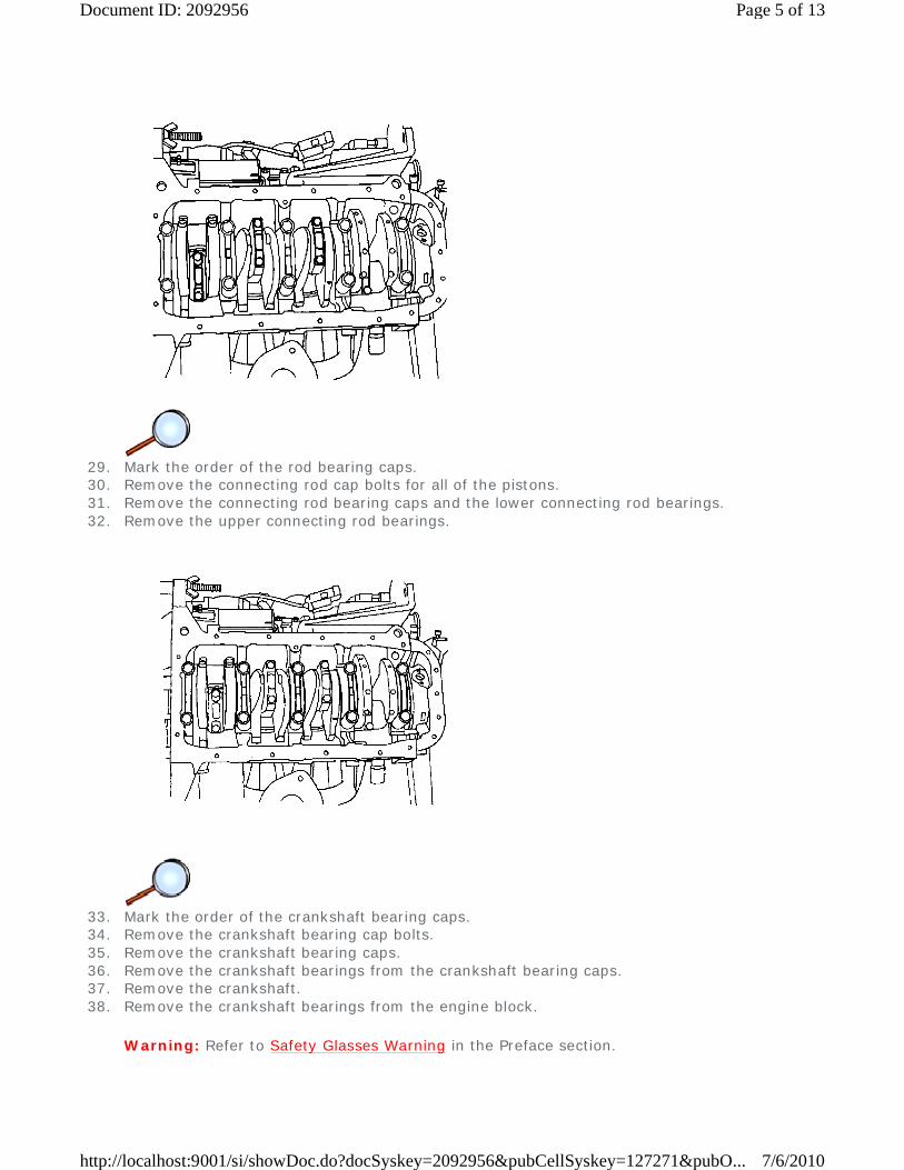
29. Mark the order of the rod bearing caps. 30. Remove the connecting rod cap bolts for all of the pistons. 31. Remove the connecting rod bearing caps and the lower connecting rod bearings. 32. Remove the upper connecting rod bearings.
33. Mark the order of the crankshaft bearing caps. 34. Remove the crankshaft bearing cap bolts. 35. Remove the crankshaft bearing caps. 36. Remove the crankshaft bearings from the crankshaft bearing caps. 37. Remove the crankshaft. 38. Remove the crankshaft bearings from the engine block.
Warning: Refer to Safety Glasses Warning in the Preface section.
Page 5 of 13Document ID: 2092956
7/6/2010http://localhost:9001/si/showDoc.do?docSyskey=2092956&pubCellSyskey=127271&pubO...

39. Clean the parts, as necessary.
Assembly Procedure
1. With crankshaft and bearings in place, plastic gage all bearing clearances. Refer to
Crankshaft and Bearing Cleaning and Inspection. 2. Inspect the crankshaft end play with the crankshaft bearings installed. 3. Inspect for permissible crankshaft end play. Refer to Engine Mechanical Specifications.
4. With the crankshaft mounted on the front and the rear crankshaft bearings, check the middle
crankshaft journal for permissible out-of-round, runout. Refer to Engine Mechanical Specifications.
Page 6 of 13Document ID: 2092956
7/6/2010http://localhost:9001/si/showDoc.do?docSyskey=2092956&pubCellSyskey=127271&pubO...

5. Coat the crankshaft bearings with engine oil. 6. Apply a bead of adhesive sealing compound to the grooves of the rear crankshaft bearing
cap. 7. Install the crankshaft bearings in the engine block. 8. Install the crankshaft.
9. Install the crankshaft bearings to the crankshaft bearing caps.
10. Install the crankshaft bearing caps.
Caution: Refer to Fastener Caution in the Preface section.
Caution: Do not reuse crankshaft bearing cap bolts. Failure to replace the crankshaft bearing cap bolts can lead to crankshaft bearing cap bolt breakage or crankshaft bearing failure. A broken crankshaft bearing bolt can lead to extensive engine damage.
Page 7 of 13Document ID: 2092956
7/6/2010http://localhost:9001/si/showDoc.do?docSyskey=2092956&pubCellSyskey=127271&pubO...

11. Install new crankshaft bearing cap bolts.
Tighten
12. Install the upper connecting rod bearings to the connecting rods. 13. Install the lower connecting rod bearings to the connecting rod bearing caps.
14. Install the connecting rod bearing caps to the connecting rods.
Note: Do not reuse the old connecting rod bearing cap bolts. Damage to the engine could result.
15. Install new connecting rod bearing cap bolts.
Tighten
• Tighten the crankshaft bearing cap bolts to 50 N·m (37 lb ft).
• Using the J 45059 or the KM-470-B (1), tighten the crankshaft bearing cap bolts another 45 degrees plus 15 degrees.
• Tighten the connecting rod bearing cap bolts to 25 N·m (18 lb ft).
• Using the J 45059 or the KM-470-B (1), tighten the connecting rod bearing cap bolts another 30 degrees plus 15 degrees.
Page 8 of 13Document ID: 2092956
7/6/2010http://localhost:9001/si/showDoc.do?docSyskey=2092956&pubCellSyskey=127271&pubO...

16. Install the oil pump. 17. Install the oil pump retaining bolts (1).
Tighten Tighten the oil pump retaining bolts to 10 N·m (89 lb in).
18. Install the oil pump/pickup tube. 19. Install the oil pump/pickup tube bolts.
Tighten Tighten the oil pump/pickup tube and support bracket bolts to 10 N·m (89 lb in).
Page 9 of 13Document ID: 2092956
7/6/2010http://localhost:9001/si/showDoc.do?docSyskey=2092956&pubCellSyskey=127271&pubO...

20. Install the oil pan gasket to the oil pan. 21. Install the oil pan.
Note: Install the oil pan within 5 minutes after applying the liquid gasket to the oil pan.
22. Install the oil pan retaining bolts.
Tighten Tighten the oil pan retaining bolts to 10 N·m (89 lb in).
23. Install the crankshaft timing belt gear.
Page 10 of 13Document ID: 2092956
7/6/2010http://localhost:9001/si/showDoc.do?docSyskey=2092956&pubCellSyskey=127271&pubO...

24. Install the rear timing belt cover. 25. Install the rear timing belt cover bolts.
Tighten Tighten the rear timing belt cover bolts to 10 N·m (89 lb in).
26. Install the timing belt automatic tensioner. 27. Install the timing belt automatic tensioner bolt (1).
Tighten Tighten the timing belt automatic tensioner bolt to 20 N·m (15 lb ft).
Note: Take extreme care to prevent any scratches, nicks, or damage to the camshaft. Such damage can impair vehicle operation.
28. Install the camshaft gear. 29. Install the camshaft gear bolt while holding the camshaft firmly in place.
Tighten Tighten the camshaft gear bolt to 45 N·m (33 lb ft).
Page 11 of 13Document ID: 2092956
7/6/2010http://localhost:9001/si/showDoc.do?docSyskey=2092956&pubCellSyskey=127271&pubO...

30. Install the timing belt. 31. Adjust the timing belt tension. Refer to Timing Belt Inspection. 32. Install the valve cover gasket and the valve cover. 33. Install the valve cover bolts.
Tighten Tighten the valve cover bolts to 9 N·m (80 lb in).
34. Install the lower timing belt cover. 35. Install the lower timing belt cover bolts.
Tighten Tighten the lower timing belt cover bolts to 10 N·m (89 lb in).
Page 12 of 13Document ID: 2092956
7/6/2010http://localhost:9001/si/showDoc.do?docSyskey=2092956&pubCellSyskey=127271&pubO...

36. Install the power steering pump. 37. Install the power steering pump mounting bolts.
Tighten Tighten the power steering pump mounting bolts to 25 N·m (18 lb ft).
38. Install the upper timing belt cover. 39. Install the upper timing belt cover bolts.
Tighten Tighten the upper timing belt cover bolts to 10 N·m (89 lb in).
40. Install the engine lifting device. 41. Dismount the engine from the KM-412 stand . 42. Install the crankshaft rear oil seal using the J 36972 (1) or KM-635 .
43. Install the flywheel. 44. Install the flywheel bolts.
Tighten
45. Install the engine. Refer to Engine Replacement.
• Tighten the flywheel bolts to 35 N·m (26 lb ft) using a torque wrench.
• Using the J 45059 or the KM-470-B , tighten the flywheel bolts another 30 degrees plus 15 degrees.
Page 13 of 13Document ID: 2092956
7/6/2010http://localhost:9001/si/showDoc.do?docSyskey=2092956&pubCellSyskey=127271&pubO...