Insulation Resistance Monitoring System (IRMS)Insulation Resistance Monitoring System Operator...
28
Airfield Solutions Insulation Resistance Monitoring System (IRMS) Operator Manual 96A0257 Rev. D
Transcript of Insulation Resistance Monitoring System (IRMS)Insulation Resistance Monitoring System Operator...

Airfield Solutions
Insulation Resistance Monitoring System (IRMS) Operator Manual
96A0257 Rev. D

Insulation Resistance Monitoring System Operator Manual Document Number 96A0257 i
Table of Contents Table of Contents .............................................................................................................................. i
1. INTRODUCTION ................................................................................................................ 1-1
1.1 FINDING YOUR WAY AROUND ................................................................................................. 1-2 1.2 SUPPORT SERVICES ............................................................................................................. 1-3
2. IRMS SYSTEM OVERVIEW .............................................................................................. 2-1
2.1 IRMS FEATURES .................................................................................................................. 2-1 2.2 SYSTEM OVERVIEW .............................................................................................................. 2-1 2.3 THEORY OF OPERATION ........................................................................................................ 2-1 2.3.1 ACE™ Assembly ........................................................................................................ 2-2 2.3.2 Insulation Resistance Module (IRM) ........................................................................... 2-2 2.3.3 IRMS Computer .......................................................................................................... 2-3 2.4 GENERAL SYSTEM OPERATION .............................................................................................. 2-4 2.4.1 Event Viewer Database .............................................................................................. 2-4 2.4.2 IRMS Database ........................................................................................................... 2-4 2.4.3 Scheduling of Readings .............................................................................................. 2-4 2.4.4 How does the IRMS Perform a Reading ..................................................................... 2-4
3. VIEWING THE IRMS DATA .............................................................................................. 3-1
3.1 USING THE GRAPHICAL USER INTERFACE SCREENS ............................................................... 3-1 3.2 IRMS VIEWER WINDOW ........................................................................................................ 3-2 3.3 COMPOSING A QUERY TO VIEW CIRCUIT DATA ....................................................................... 3-3 3.4 DISPLAYING READINGS FOR ALL THE CIRCUITS ...................................................................... 3-6
4. CONFIGURING THE IRMS ............................................................................................... 4-1
4.1 STARTING THE CONFIGURATION ............................................................................................ 4-1 4.2 CCR CONFIGURATION .......................................................................................................... 4-2
5. ENABLING AND DISABLING THE IRMS ........................................................................ 5-1
5.1 DISABLING A CIRCUIT FOR MAINTENANCE .............................................................................. 5-1 5.2 ENABLING A CIRCUIT AFTER MAINTENANCE ........................................................................... 5-3 5.3 DISABLING ENTIRE IRMS SYSTEM FOR MAINTENANCE ........................................................... 5-4 5.4 ENABLING ALL THE CIRCUITS ................................................................................................ 5-5

Table of Contents
Insulation Resistance Monitoring System Operator Manual Document Number 96A0257 ii
List of Tables FIGURE 2-1: BLOCK DIAGRAM OF IRMS SYSTEM ............................................................................. 2-2 FIGURE 3-1: STARTING THE IRMS VIEWER ...................................................................................... 3-1 FIGURE 3-2: INSULATION RESISTANCE DATA VIEWER WINDOW .......................................................... 3-2 FIGURE 3-3: CIRCUIT SELECTION WINDOW ....................................................................................... 3-3 FIGURE 3-4: RANGE SELECTION WINDOW ........................................................................................ 3-3 FIGURE 3-5: CONTROL BUTTONS ..................................................................................................... 3-4 FIGURE 3-6: GRAPHICAL DISPLAY .................................................................................................... 3-5 FIGURE 3-7: TABULAR DISPLAY ........................................................................................................ 3-6 FIGURE 3-8 ALCS MENU BAR ......................................................................................................... 3-7 FIGURE 3-9 VAULT CONTROL PROCESS: VIEWING ALL CIRCUITS ...................................................... 3-7 FIGURE 4-1 VAULT CONTROL PROCESS: CCR CONFIGURATION ....................................................... 4-1 FIGURE 4-2 CCR CONFIGURATION WINDOW .................................................................................... 4-2 FIGURE 5-1 IRMS ACTIVATION ........................................................................................................ 5-1 FIGURE 5-2 DISABLING A CIRCUIT .................................................................................................... 5-2 FIGURE 5-3 ENABLING A CIRCUIT .................................................................................................... 5-3 FIGURE 5-4 DISABLING ALL CIRCUITS ............................................................................................. 5-4 FIGURE 5-5 ENABLING ALL CIRCUITS .............................................................................................. 5-6

Insulation Resistance Monitoring System Operator Manual Document Number 96A0257 1-1
Section 1 1. Introduction With over forty years of experience in the field of airfield lighting technology, ADB Airfield Solutions (ADB) understands the importance of airport and air traffic safety. For these reasons, the Insulation Resistance Monitoring System (IRMS) is designed using only “industrial hardened” computer components which provides the customer with a system that is unmatched in performance, long-term reliability and flexibility.
The IRMS is a highly reliable and easily maintained system that is used to monitor the resistance of cable insulation used in airfield lighting series circuits. The IRMS can perform scheduled resistance measurements as well as manually requested measurements. This provides the ability for monitoring the long-term degradation of the series circuit cabling which can then be characterized in text or graphical format.
Located in the Vault, the IRMS system provides video displays of the current dielectric strength conditions of the airfield lighting circuits in text or graphical format, historical archiving of system operation and maintenance activities, and printouts of text or graphical displays. The information can also be accessed at the maintenance center computer via a communication link with the computer in the vault.
For further information or assistance, please contact the Sales Department at ADB. The telephone number is (614) 861-1304. Fax number is (614) 864-2069.

Introduction
Insulation Resistance Monitoring System Operator Manual Document Number 96A0257 1-2
1.1 Finding your way around The following sections are outlined to help in finding your way around:
Section 1: Introduction
The Introduction is an overview of ADB and the ideas behind the IRMS
Section 2: System Overview
This section reviews the components and operation of the IRMS. This section will review the system block diagram and discuss each of the subsystems.
Section 3: IRMS Graphical User Interface Screens
The IRMS Graphical User Interface Screens section illustrates the windowed, operator interface screens that are available with the IRMS system. These screens are used for evaluating and printing insulation resistance data, and system set-up and calibration procedures.
Section 4: Configuring the IRMS
This section reviews how to configure the circuit’s attributes for scheduling automatic resistant readings.
Section 5: Enabling and Disabling the IRMS
This section reviews the proper methods of disabling and enabling the IRMS system for maintenance or other purposes.

Introduction
Insulation Resistance Monitoring System Operator Manual Document Number 96A0257 1-3
1.2 Support Services ADB is committed to provide the customer with the best possible support and services from its Columbus office as well as through a network of authorized Manufacturer Representatives. ADB has an extensive line of over 200 FAA approved products. They include Constant Current Regulators, Inset Lights, Elevated Lights, Approach Systems, Taxiway signs and many more. In addition, ADB provides the following support services:
Technical assistance for installation and operation of ADB products.
Technical assistance with maintenance and troubleshooting of ADB products.
Product literature with technical specifications on current and new products.
Sales of spare parts, accessories and additional documentation Customer Support Services
To obtain product information or for ordering, please contact the ADB Customer Service Department or the nearest manufacturer representative. The Customer Service staff is available between 8:00 AM and 5:00 PM Eastern time, Monday through Friday. The telephone number is (614) 861-1304. Fax number is (614) 864-2069. Telephoning Product Support Services
When you call, you should have the appropriate product documentation at hand. Be prepared to give the following information:
What ADB product does the questions relate to
The exact wording of any messages that appeared on the Operator Interface screens (Computer System related assistance only)
What happened and what you were doing when the problem occurred
How you tried to solve the problem

Insulation Resistance Monitoring System Operator Manual Document Number 96A0257 2-1
Section 2 2. IRMS System Overview
2.1 IRMS Features The IRMS combines an industrial hardened design, high performance, and reliability with a wide range of features listed below:
Π The IRMS provides a wide range for resistance measurements from 20kΩ up to 1000MΩ. Π Resistance measurements are highly accurate at both the high and at the low ranges. Π The IRMS will operate on circuits that are Hot (Regulator ON) or Cold (Regulators OFF) with little
change in accuracy. Π Adjustable reading times and periods allow user to set up system to perform automatic resistance
measurements when they want. Π User friendly, graphical user interface screens. Π The dielectric strength measurement data can be printed out in graphical trend plots or in text
format.
2.2 System Overview The following pages are an overview of the Insulation Resistance Monitoring System (IRMS). This section provides an outline of the functionality of the IRMS and discusses the operation of the system. The IRMS consists of three (3) basic components. The components are listed below:
1.) IRMS Computer Configures and views the IRMS data. 2.) ACE™ (Advanced Control Equipment) Gathers resistance readings and communicates them
to the computer. 3.) Insulation Resistance Module (IRM) Installed in the Regulator and performs the circuit
resistance measurements. For more information and illustrations of system layout, please reference your airport’s System Block Diagram and External Wiring Diagrams.
2.3 Theory of Operation The IRMS’s primary functions are to 1.) Monitor the insulation resistance of the high voltage series circuit cable used for airfield lighting. 2) Provide long term data storage. The IRMS subsystem is able to measure and record the insulation resistance of multiple circuits so that long term degradation of the field cabling can be monitored and characterized. A block diagram of the IRMS, showing the major components of the IRMS subsystem is shown in Figure 2-1.

IRMS System Overview
Insulation Resistance Monitoring System Operator Manual Document Number 96A0257 2-2
IRMS Computer
CommunicationMulti-drop RS422 CommunicationFiber InterfaceSeries Circuit
Wiring Key:
GND
Series Circuit
CommunicationsServer
ACE #1
ConstantCurrent
Regulator#1
IRM
GND
Series Circuit
ConstantCurrent
Regulator#2
IRM
GND
Series Circuit
ConstantCurrent
Regulator#X
IRM
ACE #2 ACE #X
Figure 2-1: Block Diagram of IRMS System
2.3.1 ACE™ Assembly Associated with each Regulator is an ACE™ assembly. This is the interface between the IRMS computer and the Insulation Resistance Module (IRM). Relay Operation The ACE™’s primarily responsibility is to collect the data from the IRM in the Regulator and send this data back to the IRMS computer for viewing and archiving.
2.3.2 Insulation Resistance Module (IRM) The insulation resistance module (IRM) is installed within the Regulator or within a small enclosure located near the Regulator. It interfaces to the ACE™ via two (2) fiber optic cables. Fiber optics provides the quickest and most reliable method of interface available. The IRM generates the high voltage (50-1000VDC) that is imposed onto the series circuit. The IRM performs insulation resistance measurements by measuring the earth fault current and relays this data, via the fiber cable, back to the ACE™.

IRMS System Overview
Insulation Resistance Monitoring System Operator Manual Document Number 96A0257 2-3
Resistance Range The IRMS system can report cable resistance ranging from 20KΩ up to 1000MΩ. The results of the resistance measurement are then communicated to the IRMS computer that displays the data in text or graphical format.
Measurement Accuracy The resistance measurements recorded by the IRMS are highly accurate at both the low and high ranges.
2.3.3 IRMS Computer The IRMS computer interfaces to several ACE™ units through a communications server and is responsible for controlling the scheduling and recording of the insulation resistance measurements. From the computer keyboard, an operator can enable/disable the IRMS operation, specify what circuits should be monitored and at what time, and review or print out previously collected data. The collected data can be displayed on the computer monitor or printed to the printer in a text or graphical format and is automatically stored on the Maintenance Center computer's hard-drive. The majority of the personnel interfacing with the IRMS system will use the computer console (keyboard and monitor). From the computer console, the user can access a wide range of functions of the IRMS system through a series of user friendly, menu-driven screens referred to as the Operator Interface Screens. The following is a list of some of the possible operator functions that can be performed at the computer console:
• Enable or Disable measurement of circuits simultaneously. • Enable or Disable measurement of circuits individually. • View resistance information on the monitor screen in various time periods (i.e. days, weeks,
months or years) • Print out hard copies of resistance information to the printer as a plotted trend graph. • Print out hard copies of resistance information to the printer in tabular text format. • View an Alarm Log of circuit resistance alarms and system alarms. • View a Transaction Log of system activities.

IRMS System Overview
Insulation Resistance Monitoring System Operator Manual Document Number 96A0257 2-4
2.4 General System Operation 2.4.1 Event Viewer Database The IRMS software records any changes in operating status in the Events database. These status messages are classified into three categories: events, warnings, and alarms. The user can view the Events database to help diagnose problems with the field wiring or with the IRMS itself. In a networked IRMS system, the Event Viewer database for the entire system is stored on one of the computers, so that all transactions can be viewed from any computer in the system.
Warning and alarm messages generally relate to the user's equipment, such as circuit resistance warnings or short circuit alarms. Warnings and alarms are set when the condition is detected and cleared when condition is no longer true. For example, if a circuit's reading falls below the warning resistance level, a warning will appear in the Events database. The user has the option of viewing all alarms and warnings, or of viewing only the current alarms and warnings, which are those that haven't been cleared yet. Alarms that have an “Active 1” status are current alarms. Alarms that have a “Active 0” status, are alarms which have cleared.
2.4.2 IRMS Database The IRMS software records the resistance readings in the ALCS system’s database. In a networked IRMS system, the IRMS database for the entire system is stored on one of the computers, so that all readings can be viewed from any computer in the system. This is done using the IRMS Viewer that is discussed later in this manual.
2.4.3 Scheduling of Readings The IRMS allows considerable flexibility in selecting when the insulation resistance readings will be taken. Repetitive measurements can be scheduled by entering a start time and a sample period, and then enabling the circuit. When the start time is reached, the IRMS will attempt to measure the circuit. If a circuit is disabled for an extended time period, the start time shown may be long past. As soon as the circuit is enabled, the circuit will be read, because the start time has been reached. If the user only wants the circuit to be read at the next scheduled time (i.e. not immediately upon enabling the circuit), then he must set the desired start time before enabling the circuit. Because the system reads one circuit at a time, most measurements are made after their scheduled start time. For example, if all circuits are scheduled to be read at 1:00AM each day, then it will start reading the first circuit at 1:00AM, but depending on the circuit charge times and number of circuits enabled, it may not finish reading the last circuit until a few hours later. The scheduling of readings can only be configured at the computer location that is connected to the IRMS system. This is typically the airfield lighting vault. More information follows in the next few sections for setting up and scheduling the IRMS system.
2.4.4 How does the IRMS Perform a Reading The IRM located within the CCR or in an externally mounted enclosure is responsible for performing the insulation resistance measurements. The IRM begins by generating 50VDC, 500VDC or 1000VDC depending on the circuit’s resistance. This voltage is superimposed onto the series circuit (circuit can be ON or OFF). The IRMS will continue to charge the circuit until it reaches stabilization.
What is Stabilization? : A circuit is considered stable when a resistance reading is within 2% or less of the previous reading.

IRMS System Overview
Insulation Resistance Monitoring System Operator Manual Document Number 96A0257 2-5
After the circuit is stabilized, the IRMS will perform 10 seconds of readings taking 10 readings per second for a total of 100 readings. These readings are then averaged and the final reading is sent back to the ALCS computer system for storage.
What if circuit does not stabilize?: If after 5 minutes the circuit does not stabilize, 10 seconds of readings are completed and the averaged result is sent back to the ALCS computer. This erratic characteristic normally indicates that there is a serious problem with the circuit.
Insulation Resistance Monitoring System Operator Manual Document Number 96A0257 3-1
Section 3
3. Viewing the IRMS Data
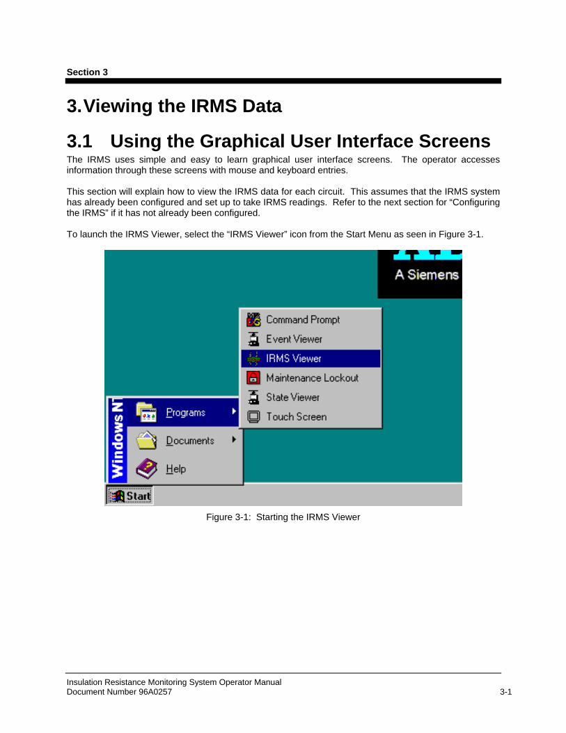
3.1 Using the Graphical User Interface Screens The IRMS uses simple and easy to learn graphical user interface screens. The operator accesses information through these screens with mouse and keyboard entries. This section will explain how to view the IRMS data for each circuit. This assumes that the IRMS system has already been configured and set up to take IRMS readings. Refer to the next section for “Configuring the IRMS” if it has not already been configured. To launch the IRMS Viewer, select the “IRMS Viewer” icon from the Start Menu as seen in Figure 3-1.
Figure 3-1: Starting the IRMS Viewer

Viewing IRMS Data
Insulation Resistance Monitoring System Operator Manual Document Number 96A0257 3-2
3.2 IRMS Viewer Window After the user selects the “IRMS Viewer” icon, the “Insulation Resistance Data Viewer” window is displayed as illustrated in Figure 3-2. This viewer is where the user can retrieve, plot and print the insulation resistance data for each of the circuits.
Figure 3-2: Insulation Resistance Data Viewer Window
In order to view resistance data, the user must select a circuit, adjust the reading range to retrieve and execute the query (A query is when the computer system searches and retrieves information from the database based on the inputs that the user has selected). Continue to the next sections on instructions for retrieving IRMS data.
Data Viewing Window

Viewing IRMS Data
Insulation Resistance Monitoring System Operator Manual Document Number 96A0257 3-3
3.3 Composing a Query to View Circuit Data Step 1: Circuit Selection
The area located in the upper left corner is referred to as “Circuit Selection” window as shown in Figure 3-3. This area lists all the airfield lighting circuits that are associated with the IRMS. To select a circuit to view, simply highlight the circuit using the mouse cursor and selecting the circuit. Use the scroll bars as necessary to search through the listing for the specific circuit you wish to view. After a circuit is selected, move to step 2.
Figure 3-3: Circuit Selection Window
Step 2: Adjusting the Reading Range
The area located in the upper right corner is referred to as “Range Selection” window as shown in Figure 3-4. This area is used to specify what time period of data the user is interested in viewing. The user must specify a specific “From:” time and an ending “To:” time in order to retrieve the resistance data (The default for both fields is the current date and time). To change either field, use the Up/Down toggle buttons until the time period is correct. The time periods toggle adjustments default to “Minutes”, but can easily be changed to any of the following options by selecting the corresponding button options: Years, Months, Days, Hours. For example, if “Months” is selected, each press of the Up toggle button will cause the “From:” or “To:” field to increase by 1 Month.
Figure 3-4: Range Selection Window
Up/Down Toggle buttons
Scroll bar

Viewing IRMS Data
Insulation Resistance Monitoring System Operator Manual Document Number 96A0257 3-4
Step 3: Executing the Query
The “Control Buttons” located under the “Range Selection” window as shown Figure 3-5 is used to execute the query process and also to adjust the format in which the data is viewed. Once the circuit has been selected and the Range is adjusted, the user must select the “Query” button to execute the retrieval process. The IRMS system will then retrieve the data and display the information in the Data Viewing window as seen in Figure 3-2. The default mode for displaying the data is in graphical format, but can be changed to tabular view. Continue to the next step.
Figure 3-5: Control Buttons

Viewing IRMS Data
Insulation Resistance Monitoring System Operator Manual Document Number 96A0257 3-5
Step 4: Changing Viewing Format and Printing
Graphical Viewing:
An example of the graphical data display is seen in Figure 3-6. The insulation resistance values are displayed along the left (Y-axis) and the time values are displayed along the bottom (X-axis). To change the view to a tabular format (text view), select the “Tabular” button.
Figure 3-6: Graphical Display

Viewing IRMS Data
Insulation Resistance Monitoring System Operator Manual Document Number 96A0257 3-6
Tabular Viewing: The “Tabular” view as seen in Figure 3-7 will list in chronological order (most recent reading listed first) the following information:
a. CCR Name: Circuit(s) requested in the query
b. Meg: The resistance reading recorded
c. Time: The date/time the resistance reading was taken.
If the query information exceeds the display window, you will have to use the scroll bars along the right side of the screen to move up and down in the display window.
Figure 3-7: Tabular Display
Printing: To print the data (graphical or tabular), select the “Print” button. The displayed data will be printed out on the connected printer.
3.4 Displaying Readings for All the Circuits Another method of viewing the insulation resistance data is using the “Vault Control Process” window. Here the user can see every circuit and the last recorded IRMS reading. Open the “Vault Control Process” from the Menu bar located along the bottom of the desktop screen. See Figure 3-8 below. (This is covered in the ALCS Operator Manual)

Viewing IRMS Data
Insulation Resistance Monitoring System Operator Manual Document Number 96A0257 3-7
Figure 3-8 ALCS Menu Bar
Single-click on the “Vault Control Process” icon and this will launch the process. A window will appear as seen in Figure 3-9. This window lists all of the circuits configured in the ALCS system and displays other information as it relates to the lighting control system (i.e. Primary Power status, Remote/Local status, Current and Voltage). The most recent IRMS reading is also listed as shown below. Use the scroll bars as necessary to search through the listing for the specific circuit you wish to view.
Figure 3-9 Vault Control Process: Viewing All Circuits
5.4M
15.7M
8.2M
7.4M

Insulation Resistance Monitoring System Operator Manual Document Number 96A0257 4-1
Section 4
4. Configuring the IRMS
4.1 Starting the Configuration Before the IRMS system can perform scheduled resistance measurements, all of the circuits must be configured. This section will explain how to configure the IRMS circuits including setting alarm/warning limits and schedule reading times. First, you must open the Vault Control Process as outlined in the previous section as well as the ALCS Operator Manual. Next, open the configuration window by selecting the “CCR configuration…” button as seen in Figure 4-1.
Figure 4-1 Vault Control Process: CCR configuration

Configuring the IRMS
Insulation Resistance Monitoring System Operator Manual Document Number 96A0257 4-2
4.2 CCR Configuration After you have selected the “CCR configuration…” button, the window as seen in Figure 4-2 is opened. The IRMS configuration changes will be performed in the section title “Insulation resistance configuration” as highlighted below.
Figure 4-2 CCR Configuration Window

Configuring the IRMS
Insulation Resistance Monitoring System Operator Manual Document Number 96A0257 4-3
CCR Configuration Information Please note that the “Lamps out configuration” and the “Incorrect current configuration” sections are covered in detail in the ALCS Manual and are not part of the Insulation Resistance configuration. Step 1: Select the CCR to configure
Use the pull-down button associated with the “CCR to configure” field to select the circuit or CCR name that you wish to change its configuration data. Insulation resistance configuration
Step 2: Setting the Warning Level:
This is a limit value at which point a resistance warning will be generated. If a resistance reading is below this value, the warning message will be sent to the event database. When the value goes above this level, the warning will be marked as cleared in the event database. This number can be any value between 20000 (20 kOhm) and 1000000000 (1 G Ohm). Values near 20k Ohms represent circuit shorts. Note: The warning limit must be larger than the alarm limit.
To adjust the “Warning Level”, enter a number in the field and select one of the three mulipliers, “K Ohm”, “M Ohm” or “G Ohm”
Step 3: Setting the Alarm Level:
Alarm Level: Error! Not a valid link. This is a limit value at which point a resistance alarm will be generated. If a resistance reading is below this value, the alarm will be sent to the event database. When the value goes above this level, the alarm will be marked as cleared in the event database. This number can be any value between 20000 (20 kOhm) and 1000000000 (1 G Ohm). Values near 20k Ohms represent circuit shorts. Note: The alarm limit must be lower than the warning limit.
To adjust the “Alarm Level”, enter a number in the field and select one of the three mulipliers, “K Ohm”, “M Ohm” or “G Ohm”

Configuring the IRMS
Insulation Resistance Monitoring System Operator Manual Document Number 96A0257 4-4
Step 4: Setting the First Sample time:
The first sample time is the day and time that the IRMS system will take an insulation resistance reading.
“Day:” Using the drop-down box, select the day of the week that you want the readings to be taken.
“Time:” Using the toggle up/down buttons, change to value until it is the time of day that you want the reading to be taken.
“Period:” Using the drop-down box, select how often you want the reading to be taken. Options are daily, weekly, bi-weekly, monthly, bi-monthy.
Step 5: Setting the “Voltage applied to circuit”:
This allows the user to specify a maximum voltage to use during resistance readings. This is primarily used with smaller CCRs sizes that may have output lightning protection that activates at voltages greater than 500VDC. Refer to the CCR manual to determine if this applies.
This value can be set for 50, 500 or 1000VDC. Typically, the IRMS system will auto-range with the correct voltage value to establish an accurate reading. The system will default to 1000VDC for resistance readings. To change the voltage, use the drop-down button and select the desired voltage.
Step 6: Setting the Second Sample time: [OPTIONAL]
The second sample time is the day and time that the IRMS system will take a 2nd insulation resistance reading. This setting is optional and is used only if you require two readings to be performed on the same day or twice a week. To enable the second sample time, select the “Enable second sample” check-box.
“Day:” Using the drop-down box, select the day of the week that you want the second readings to be taken.
“Time:” Using the toggle up/down buttons, change to value until it is the time of day that you want the second reading to be taken.
“Period:” Using the drop-down box, select how often you want the second reading to be taken. Options are daily, weekly, bi-weekly, monthly, bi-monthy.
Step 7: Saving the configuration changes:
You have two options when saving the configuration changes.
Save changes for only one circuit:
To save the changes for the selected circuit only, Select the “Apply” button.
Duplicate changes for ALL circuits:
To apply the changes to ALL the circuits, Select the “Apply insulation resistance configuration to all circuits” button. After selecting this button, you must confirm by selecting the “Yes” button from the window. Step 8: Exiting configuration changes:
When configuration changes are complete, select the “Ok” button to exit. To exit the configuration window without saving the information, select the “Cancel” button.

Enabling and Disabling the IRMS
Insulation Resistance Monitoring System Operator Manual Document Number 96A0257 5-1
Section 5
5. Enabling and Disabling the IRMS This section will deal primarily with explaining the proper procedures for powering up and starting the operation of the IRMS system as well as powering down and shutting off the system for repair or maintenance.
WARNING:To prevent personal injury from electrical shock, it is important to readall instructions for System Start-up and Shut-down procedures beforeperforming any repair or maintenance of the system.
CAUTION:To prevent equipment damage, it is important to read all instructions forSystem Start-up and Shut-down procedures before performing anyrepair or maintenance of the system.
5.1 Disabling a Circuit for Maintenance This section will deal with explaining the proper procedures for disabling a circuit for maintenance.
Figure 5-1 IRMS activation

Enabling and Disabling the IRMS
Insulation Resistance Monitoring System Operator Manual Document Number 96A0257 5-2
Step 1: Select the IRMS Activation Screen
To disable an individual circuit so that it will not perform automatic resistance readings, select the “IRMS activation…” button from the Vault Control Process window as seen in Figure 5-1. A pop-up window will appear as seen in Figure 5-2.
Step 2: Disable a Circuit
From the pop-up window select the circuit from the “Enabled circuits:” window and then select the “Disable >>” button as seen in Figure 5-2. This will place the circuit in the “Disable circuits:” window.
Figure 5-2 Disabling a Circuit
Step 3: Disable the Power to the IRMS System
Locate the power for the Insulation Resistance Module associated with the circuit and switch the power OFF.
Step 4: Disable the Constant Current Regulator
Turn OFF the primary power for the Constant Current Regulator to be worked on.
Step 5: Isolate the Series Circuit Cabling
If S-1 Cut-Outs are present, remove the cut-out. If L-823 cord set plugs are used, disconnect the series circuit from the regulator and short the CCR output. At this point, the circuit is ready to assume maintenance.

Enabling and Disabling the IRMS
Insulation Resistance Monitoring System Operator Manual Document Number 96A0257 5-3
5.2 Enabling a Circuit After Maintenance This section will deal with explaining the proper procedures for enabling a circuit once maintenance is complete. Step 1: Reconnect Series Circuit Cabling
If S-1 Cut-Outs are present, replace the cut-out. If L-823 cord set plugs are used, reconnect the series circuit to the regulator. Step 2: Enable the Constant Current Regulator
Turn ON the primary power for the Constant Current Regulator. Step 3: Enable Power to the IRMS System
Locate the power for the Insulation Resistance Module associated with the circuit and switch the power ON.
Step 4: Enable the Circuit from the IRMS Activation Screen
From the pop-up window select the circuit from the “Disabled circuits:” window and then select the “<< Enable” button as seen in Figure 5-3. This will place the circuit in the “Enabled circuits:” window.
At this point, the circuit is now returned to normal. The IRMS system will begin readings at the next scheduled time.
Figure 5-3 Enabling a Circuit

Enabling and Disabling the IRMS
Insulation Resistance Monitoring System Operator Manual Document Number 96A0257 5-4
5.3 Disabling Entire IRMS System for Maintenance This section will deal with explaining the proper procedures for disabling the entire IRMS system such that all circuits can be worked on. Step 1: Disable all circuits from the IRMS Activation Screen
To disable ALL circuits so that it will not perform any automatic resistance readings, select the “Disable all >>” button as seen in Figure 5-4. This will place all the circuits in the “Disabled circuits:” window.
Figure 5-4 Disabling ALL Circuits
Step 2: Disable the Power to the IRMS System
Locate the power for the Insulation Resistance System and switch the power OFF. Important Note: For Systems that use UPS battery back-up power, make sure to turn OFF the UPS associated with the IRMS System. Step 3: Disable the Constant Current Regulator
Turn OFF the primary power for all the Constant Current Regulators to be worked on.
Step 4: Isolate the Series Circuit Cabling
If S-1 Cut-Outs are present, remove all the cut-outs for each circuit to be worked on. If L-823 cord set plugs are used, disconnect the series circuit from all the regulators and short the CCR outputs. At this point, the circuits are ready to assume maintenance.

Enabling and Disabling the IRMS
Insulation Resistance Monitoring System Operator Manual Document Number 96A0257 5-5
5.4 Enabling ALL the Circuits This section will deal with explaining the proper procedures for enabling ALL of the circuits. In order for the IRMS system to perform its scheduled resistance readings, the circuits must be enabled. Step 1: Reconnecting Series Circuit Cabling
If S-1 Cut-Outs are present, replace all the cut-outs for each circuit worked on. If L-823 cord set plugs are used, reconnect the series circuit from all the regulators. Step 2: Enable the Constant Current Regulator
Turn ON the primary power for all the Constant Current Regulators worked on.
Step 3: Enable the Power to the IRMS System
Locate the power for the Insulation Resistance System and switch the power ON. Important Note: For Systems that use UPS battery back-up power, make sure to turn ON the UPS associated with the IRMS System.
Enabling and Disabling the IRMS
Insulation Resistance Monitoring System Operator Manual Document Number 96A0257 5-6
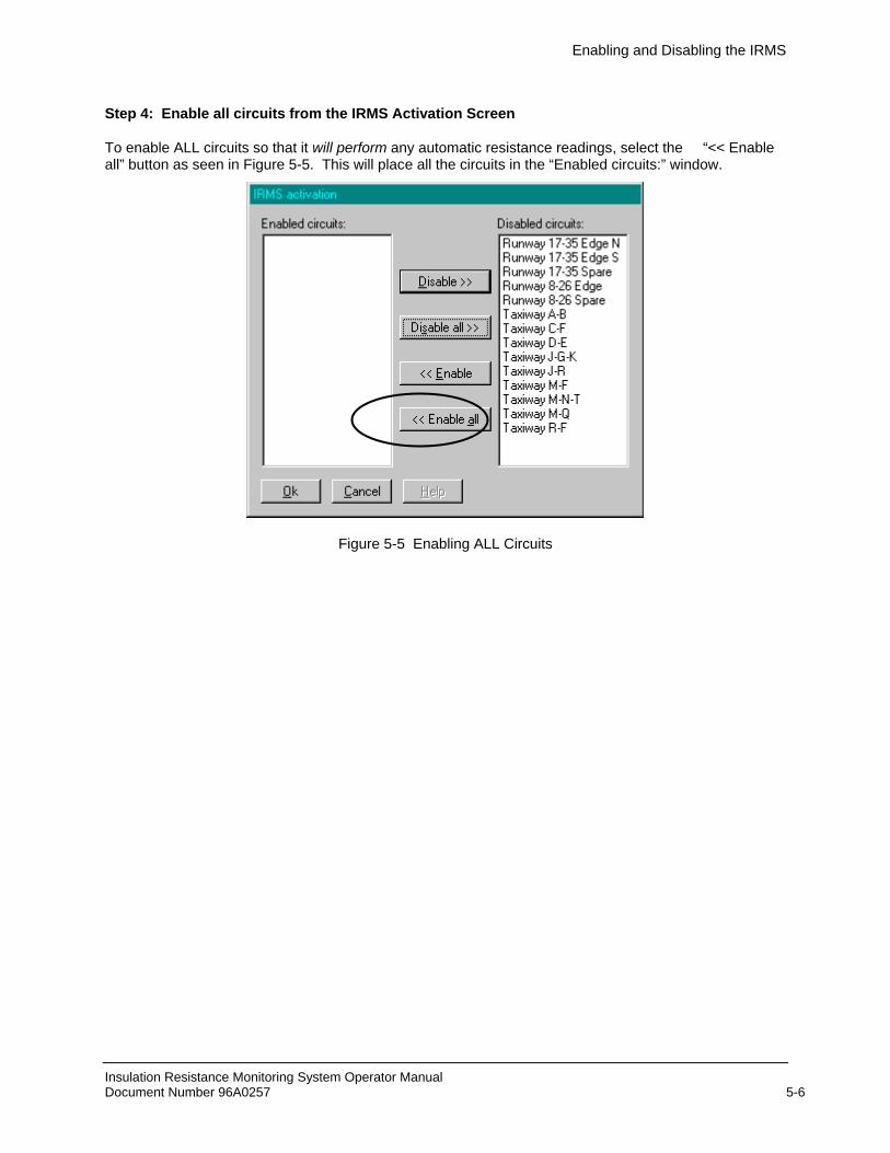
Step 4: Enable all circuits from the IRMS Activation Screen
To enable ALL circuits so that it will perform any automatic resistance readings, select the “<< Enable all” button as seen in Figure 5-5. This will place all the circuits in the “Enabled circuits:” window.
Figure 5-5 Enabling ALL Circuits