Insulation for VRF/VRV HVAC Systems · PDF file · 2017-08-28Insulation for VRF/VRV...
23
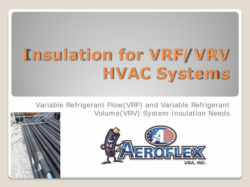
Insulation for VRF/VRV HVAC Systems Variable Refrigerant Flow(VRF) and Variable Refrigerant Volume(VRV) System Insulation Needs
Transcript of Insulation for VRF/VRV HVAC Systems · PDF file · 2017-08-28Insulation for VRF/VRV...
Insulation for VRF/VRV HVAC Systems
Variable Refrigerant Flow(VRF) and Variable Refrigerant Volume(VRV) System Insulation Needs

VRF/VRV System Insulation Installation Needs
Well Sealed, Skill/Detail High Level of Craftsmanship Complete Insulation Envelope – All Parts Installation Longevity High Volume of Small Pipe Sizes, Thick Walls Unique Fitting Configurations Higher Service Temperature Excellent Moisture Resistance Flexibility Non-Corrosive Resistance to Weathering Superior Fire Resistance Sustainable Construction

VRF/VRV Manufacturers’ Insulation Requirements
VRF/VRV Systems Condensate Drain and Refrigeration Piping Insulation Requirements
Manufacturer Service Upper Service Temperature
Lower Service Temperature
Thickness, Minimum
Thickness, Maximum Types Mentioned
Carrier(Toshiba) Cond. Drain N/A N/A .4" N/A Polyethylene
Refrigerant Pipe 248°F N/A N/A N/A -- Local Code N/A
Daikin Cond. Drain NONE NONE NONE NONE NO MENTION
Refrigerant Pipe 248°F 30°F 1/2", 3/4" Conflicts N/A -- Local Code Fiberglass, Poly
Fujitsu Cond. Drain NO MENTION NO MENTION NO MENTION NO MENTION NO MENTION
Refrigerant Pipe 248°F 3/8" 1"
LG Cond. Drain N/A N/A N/A N/A As Necessary
Refrigerant Pipe 248°F/227°F -4°F 1/2" 1" Closed-Cell/EPDM
Mitsubishi Cond. Drain N/A N/A 3/8" N/A Polyethylene
Refrigerant Pipe 212°F N/A 3/8", 1/2" 3/4" or more Fiberglass, Poly
Samsung Cond. Drain NON-SPECIFIC N/A N/A N/A NON-SPECIFIC
Refrigerant Pipe 248°F N/A 3/8" 1-1/2" EPDM
Toshiba Cond. Drain N/A N/A .4" Polyethylene
Refrigerant Pipe 248°F N/A N/A N/A -- Local Code N/A
Trane(Samsung) Cond. Drain NON-SPECIFIC N/A N/A N/A NON-SPECIFIC
Refrigerant Pipe 248°F N/A 3/8" 1-1/2" EPDM

VRF System Insulation Code Requirements
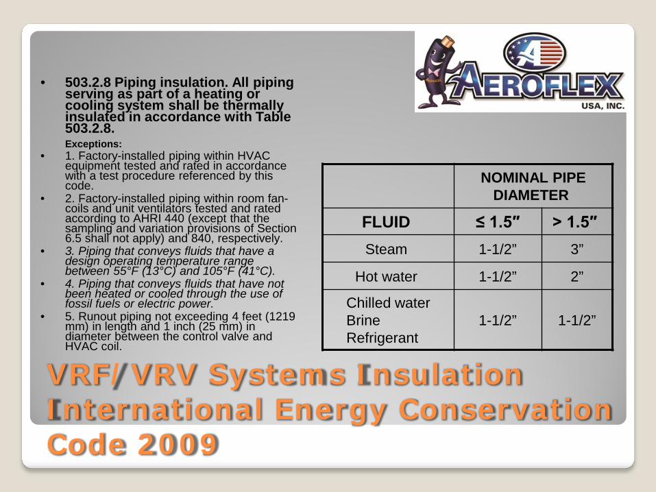
VRF/VRV Systems Insulation International Energy Conservation Code 2009
• 503.2.8 Piping insulation. All piping serving as part of a heating or cooling system shall be thermally insulated in accordance with Table 503.2.8. Exceptions:
• 1. Factory-installed piping within HVAC equipment tested and rated in accordance with a test procedure referenced by this code.
• 2. Factory-installed piping within room fan-coils and unit ventilators tested and rated according to AHRI 440 (except that the sampling and variation provisions of Section 6.5 shall not apply) and 840, respectively.
• 3. Piping that conveys fluids that have a design operating temperature range between 55°F (13°C) and 105°F (41°C).
• 4. Piping that conveys fluids that have not been heated or cooled through the use of fossil fuels or electric power.
• 5. Runout piping not exceeding 4 feet (1219 mm) in length and 1 inch (25 mm) in diameter between the control valve and HVAC coil.
NOMINAL PIPE DIAMETER
FLUID ≤ 1.5″ > 1.5″ Steam 1-1/2” 3”
Hot water 1-1/2” 2”
Chilled water Brine Refrigerant
1-1/2” 1-1/2”
International Energy Conservation Code 2015
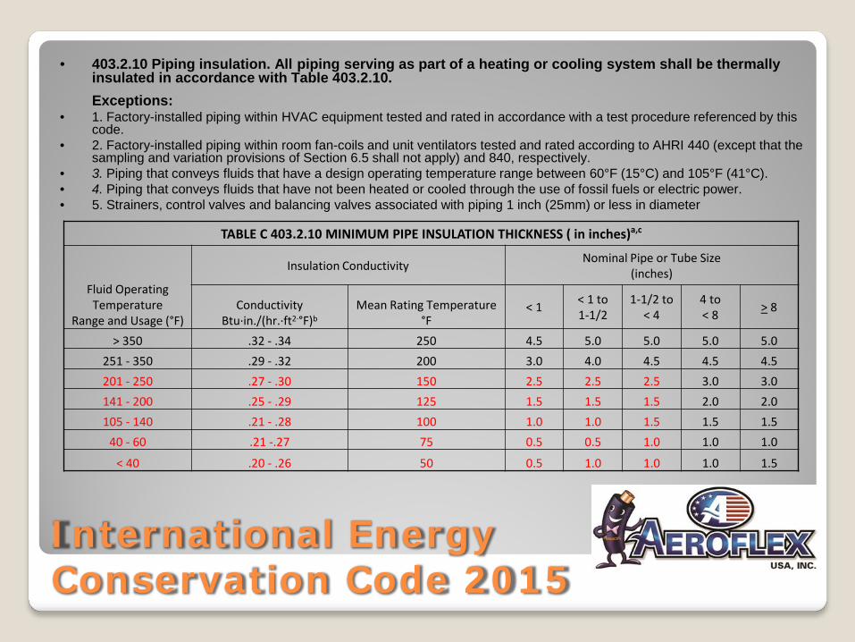
• 403.2.10 Piping insulation. All piping serving as part of a heating or cooling system shall be thermally insulated in accordance with Table 403.2.10. Exceptions:
• 1. Factory-installed piping within HVAC equipment tested and rated in accordance with a test procedure referenced by this code.
• 2. Factory-installed piping within room fan-coils and unit ventilators tested and rated according to AHRI 440 (except that the sampling and variation provisions of Section 6.5 shall not apply) and 840, respectively.
• 3. Piping that conveys fluids that have a design operating temperature range between 60°F (15°C) and 105°F (41°C). • 4. Piping that conveys fluids that have not been heated or cooled through the use of fossil fuels or electric power. • 5. Strainers, control valves and balancing valves associated with piping 1 inch (25mm) or less in diameter
TABLE C 403.2.10 MINIMUM PIPE INSULATION THICKNESS ( in inches)a,c
Fluid Operating Temperature
Range and Usage (°F)
Insulation Conductivity Nominal Pipe or Tube Size (inches)
Conductivity Btu·in./(hr.·ft2·°F)b
Mean Rating Temperature °F
< 1 < 1 to 1-1/2
1-1/2 to < 4
4 to < 8 > 8
> 350 .32 - .34 250 4.5 5.0 5.0 5.0 5.0 251 - 350 .29 - .32 200 3.0 4.0 4.5 4.5 4.5 201 - 250 .27 - .30 150 2.5 2.5 2.5 3.0 3.0 141 - 200 .25 - .29 125 1.5 1.5 1.5 2.0 2.0 105 - 140 .21 - .28 100 1.0 1.0 1.5 1.5 1.5
40 - 60 .21 -.27 75 0.5 0.5 1.0 1.0 1.0
< 40 .20 - .26 50 0.5 1.0 1.0 1.0 1.5

VRF/VRV Piping Systems
Copper
Aluminum
Flexible Composite
Copper Line Set
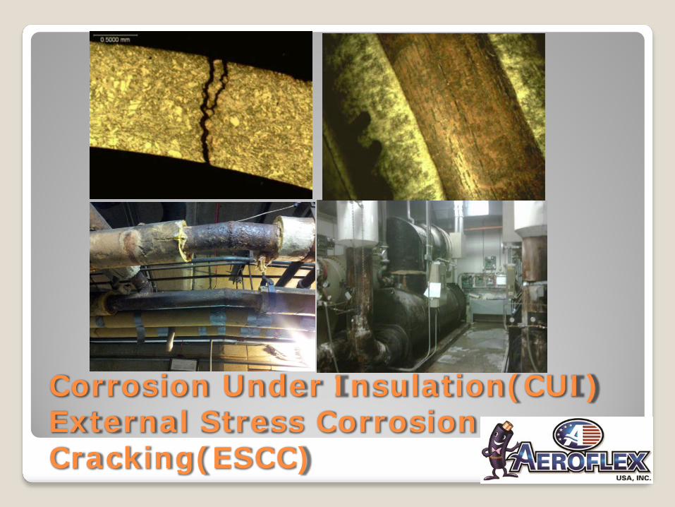
Corrosion Under Insulation(CUI) External Stress Corrosion Cracking(ESCC)

Corrosion Under Insulation(CUI) External Stress Corrosion Cracking(ESCC)
How Does CUI and ESCC Happen? Corrosion Under Insulation usually results from the ingress of water (or other types of corrosive solvents) into the insulation Insulation can contain corrosive chemicals which turn to acidic substances, especially under heat or combustion. Microorganisms can cause microbial corrosion. Some microorganisms oxidize iron into iron oxides or iron hydroxides, forming rust. Some microorganisms emit chemically-polar acids that damage both metal surfaces and the insulation itself. Contaminants in the plant environment can accelerate corrosion.

Corrosion Under Insulation(CUI) External Stress Corrosion Cracking(ESCC)
How To Avoid CUI and ESCC Design, install, and maintain insulation systems to minimize ponding water or penetration of water into the system. Insulation should be appropriate for its intended application and service temperature. The insulation characteristics with the most influence on CUI are: (1) water-leachable salt content in insulation -- chloride, sulfate, and acidic materials in fire retardants and processing aids (2) water retention, permeability, and wettability of the insulation (3) foams containing residual compounds that react with water to form hydrochloric or other acids.

VRF Insulation Material Comparisons
MATERIAL
PROPERTY Aerocel EPDM PIR Phenolic NBR/PVC Fiberglass Polyethylene
PUBLISHED DATA
Thermal Conductivity 0.245 0.19 0.15 .25/.28 0.235 0.25
Upper Service Temp. 257°F/300°F 300°F 257°F 180°F/220°F 850/1000°F 190°F
Lower Service Temp -297°F -297°F -297°F -297°F 0°F -330°F
Water Vapor Perm. 0.03 4 2 .05/.08 Unlimited 0.02
Water Absorbtion < .2% < .7% 0.9% 0.2% UNKNOWN UNKNOWN
Flame/Smoke 25/50 25/450 25/50 25/50 25/50 25/50
Self-Extinguishing Y N N N UNKNOWN N
Significant HCN/HCl N/N Y/Y Y/Y Y/Y N/N N/N
Weather/UV Resistant Y N N N N N
Additional Finishes N Y Y Y Y Y
Close Cell Content 100% 90% 95% 92% 0 100%
Flexibility Y N N Y N SEMI
Corrosiveness N Y Y Y Y UNKNOWN
ID's 1/4" - 16" 1/4" - 12" 1/4" - 12" 1/4" - 8" 5/8"- 30" 3/8" - 4"
Thickness 3" 6" 6" 2" 3" 1" MAX

VRF System Insulation Biggest Failure Points
No or Improper Seam Closure
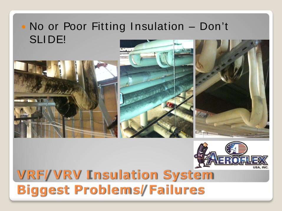
No or Poor Fitting Insulation – Don’t SLIDE!
No or Poor Anchoring Device (Hanger) Insulation
Stretching Insulation
No Spacing Between Pipes
No Vapor Stopping
Improper Termination at Equipment
No Protective Finish When Required

VRF/VRV Insulation System Biggest Problems/Failures
No or Improper Seam Closure
VRF/VRV Insulation System Biggest Problems/Failures
No or Poor Fitting Insulation – Don’t SLIDE!

VRF/VRV Insulation System Biggest Problems/Failures
No or Poor Anchoring Insulation Improper Support at Anchor Locations Tight Pipe Rack Spacing

Piping Support
Support at Hangers – ASHRAE Handbook of Fundamentals, Chapter 23 Mechanical Insulation ◦ “When avoiding compression of low compressive-strength
insulation products is the goal, it is recommended that high-strength insulation inserts, made of a product that offers the desired compressive strength and other necessary performance properties, be used. Note that the old method of using wood blocks instead of a high strength insulation insert is not recommended, especially for cold pipe systems. Other higher strength materials that are not thermal insulation material and interrupt the insulation envelope, or do not allow complete sealing of an insulation system against water vapor ingress, are not recommended for the support of insulated piping on pipe hangers.”

VRF/VRV Insulation System Biggest Problems/Failures
No Protective Finish When Required

The Aerocel® Oranges – Advantages of EPDM Insulation
BEST “K-Value” at 0.245; Deliver Lower Energy Costs than Others
BEST UV Resistance; Save on First Cost and Long Term Ownership Cost
BEST Self-Sealed System (SSPT with Cel-Link® II); Reduce Installation Costs, Gets Projects Done, Meets LVOC Needs
BEST Water Vapor Transmission Rate (WVTR), .03 Perms; Maintain Energy Savings, Avoids Mold Growth, Enhances System Life
BEST Service Temperature for ASTM C 534 Type I Grade 1, +257°F (300°F – Non-SSPT); Widest Range of Applications
Superior Fire Safety Properties; Meets and exceeds life safety requirements
Stays Flexible in Cold Weather; Keep Job Costs in Check, Keep Installers Working
Low Halogens Content; Avoid Cost from External Stress Corrosion Cracking (ESCC) on Stainless Steel or Copper Tubing

Polar vs. Non-Polar (NBR/PVC vs. EPDM)
NBR/PVC = Polar Material (Atomically Charged) Less Stable Deteriorates with the application of energy through: - Chemical reaction -- As with water, ozone, or other solvents - Heat energy – As applied by mechanical systems or environment - Light Energy – UV light highly detrimental
EPDM = Non-Polar Material (Atomically Neutral) Highly Stable No reactivity because of balanced atomic structure
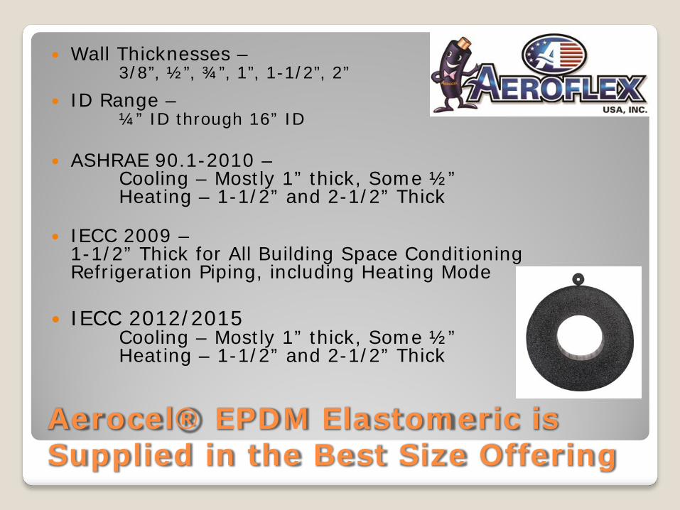
Aerocel® EPDM Elastomeric is Supplied in the Best Size Offering
Wall Thicknesses – 3/8”, ½”, ¾”, 1”, 1-1/2”, 2”
ID Range – ¼” ID through 16” ID
ASHRAE 90.1-2010 –
Cooling – Mostly 1” thick, Some ½” Heating – 1-1/2” and 2-1/2” Thick
IECC 2009 – 1-1/2” Thick for All Building Space Conditioning Refrigeration Piping, including Heating Mode
IECC 2012/2015 Cooling – Mostly 1” thick, Some ½” Heating – 1-1/2” and 2-1/2” Thick

VRF System Insulation Installation Solutions
Aerocel® AC and Aerocel® SSPT with Cel-Link® II(Video)
Aerofix®-U
AeroFit
Aeroseal Adhesive
Protape™
Aerocel® with SaniGuard

VRF/VRV Key Points Of Installation
The Hermetic System EPDM-BASED
HIGH-PERFORMANCE AEROCEL® Sealed – Including PROPER Vapor Stopping No Compression Correct Anchoring No Sliding Fittings ID/Thicknesses Non Corrosive

Aerocel® – The Right Elastomeric Insulation for VRF/VRV Systems
Thank You for Your Time