Insulation Coordination - University of Over-Voltage – Any voltage ... voltage, the value of...
131
Insulation Coordination in the Alberta Interconnected Electric System Part 1 Ligong Gan, P.Eng. Transmission Engineering & Performance Alberta Electric System Operator (AESO)
-
Upload
vuongkhanh -
Category
Documents
-
view
269 -
download
3
Transcript of Insulation Coordination - University of Over-Voltage – Any voltage ... voltage, the value of...

Insulation Coordination in the Alberta Interconnected Electric System
Part 1
Ligong Gan, P.Eng. Transmission Engineering & Performance Alberta Electric System Operator (AESO)

2
AGENDA
• Why do we need insulation?
• What is insulation coordination?
• Recap of May 13/15 2014 Course by Dr. Peelo – Temporary over-voltages – Switching over-voltages – Lightning over-voltages
• Typical approaches to insulation coordination
• IEEE and IEC standards
• Q&A

Before Lightning Rod was Invented…
3
• Lightning has always been a prominent part of all ancient religions and mythologies in the world
• In the old days, lightning was considered an act of god(s) to express their anger
• For example In the Middle Ages in Europe, it was common practice to ring church
bells during a lightning storm to break up thunderstorms and to avert lightning
The uneducated people believed that this would disperse evil spirits, while the more educated believed that it would cause vibration in air which broke up the continuity of the lightning path
However, during a 33 year period, 386 church steeples were hit by lightning, killing 103 bell ringers at the rope

Characteristics of Lightning
4
• 2000 lightning occurrences on the earth by the time you finish reading this slide
• A lightning flash typically lasts for 0.2s
• Usually made of several shorter discharges, each of which lasts for 10 to 50 µs
• Typical length of lightning path is 2-3 km
• Individual discharges are called “strokes”
• Most visible when return stroke occurs
• Lightning bolt can carry a potential difference of >1000 kV and >100 kA with >20 GJ

Lightning Facts of Alberta
5
• In an average year, 270,000 cloud-to-ground (CG) lightning strikes occur in Alberta (in contrast, Manitoba has only 70,000 per year)
• Most CG lightning occurs in the mountain and west-central areas
• Virtually all CG lightning strikes occur in July (45%), August (32%) and June (23%)
• On a typical day, most lightning strikes happen between 3:00 pm and 11:00 am
• Average lightning strike density in Alberta is only 0.8 to 1 s/km2 • The worst strike density is about 4 s/km2, mainly in two areas, one 20 km north of Edson, and the other 50 km southeast of Edson
• The least density is 0.1 s/km2 in the north and far southeast
Source – Alberta Environment and Sustainable Resource Development (ESRD) website

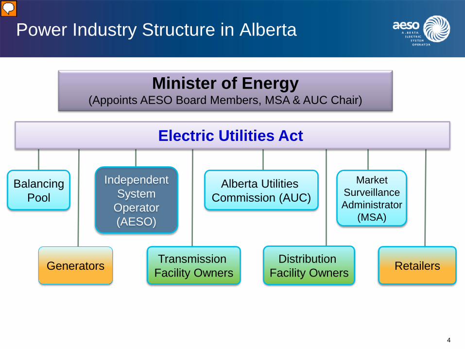
Power Industry Structure in Alberta
Electric Utilities Act
Market Surveillance Administrator
(MSA)
Balancing Pool
Alberta Utilities Commission (AUC)
Transmission Facility Owners
Distribution Facility Owners Retailers
Independent System
Operator (AESO)
Minister of Energy (Appoints AESO Board Members, MSA & AUC Chair)
Generators
6
Presenter
Presentation Notes

What is AESO?
7
The AESO – • Was formed in 2003 under the Electric
Utilities Act (EUA)
• Contracts with TFOs to acquire transmission services
• Develops and publishes binding ISO rules and standards
• Develops and issues Functional Specifications for projects
• Works closely with TFOs and market participants on transmission projects

Why Do We Need Insulation?
8
1. Public and utility personnel safety
2. Ensure current flows only along conductors
3. Prevent damage to equipment due to high voltage. In particular, prevent or reduce permanent damage to
– Transformers – Cables

How Insulation Breakdown Takes Place
9
• Chemical – Oxidation, hydrolysis, etc.
• Mechanical – Cracks, channels, tracks, deforming, etc.
• Thermal – Overheating (e.g., transformers are generally limited to 2 seconds over-current)
Failure Rate Failure Rate
HV xformers 0.1% Cables ≥ 25 kV 83% of all failures
LV xformers 0.15% CTs 0.35%
HV shunt reactors 0.4% PTs 0.2%
HV breakers 0.09% Surge arresters 0.01%
Typical failure rate of equipment due to insulation breakdown
Source: Research conducted by Bueno & Mak Group.

Insulation Coordination – Definition
10
IEEE 1313.1 – The selection of the insulation strength of equipment in relation to the voltages, which can appear on the system for which the equipment is intended and taking into account the service environment and the characteristics of the available protective devices
IEC 60071-01 – Selection of the dielectric strength of equipment in relation to the operating voltages and over-voltages which can appear on the system for which the equipment is intended, taking into account the service environment and the characteristics of the available preventing and protective devices
Plain Language – Arrangement of insulation levels in such a manner that an insulation failure, if one occurs, would be confined to the place on the system where it would result in the least damage, be the least expensive to repair and cause the least disturbance to the continuity of supply

Insulation Coordination (cont.)
11
Keep in Mind • It’s impossible to design a
system that is 100% protected
• No perfect solution – practicality is the key
• Insulation coordination is both an art and science
• Insulation coordination is often an economic decision
Number of insulator units
Over-Voltage

An Example of Insulation Coordination
12
• Tower type steel
• Shielding wire Yes
• Line BIL = 1050 kV
• Transformer BIL = 850 kV
• Breaker BIL = 1050 kV
• Switch & post insulators BIL = 900 kV
• Arrester – Continuous voltage = 190 kV
– Discharge voltage = 600 kV
• Separation distance ≤ 3 m between arrester & xformer (as per IEEE C62.22)
Tower & Line
Breaker
Transformer
Arrester
240 kV system
Recap of May 13/15 2014 Course “Insulation Coordination” by Dr. Peelo
13
• The following voltages are always phase-to-phase r.m.s. values
– Nominal system voltage – Minimum continuous operating voltage – Maximum continuous operating voltage (MCOV)
• The following voltage is phase-to-ground r.m.s. value – Short-duration low-frequency withstand voltage
• The following voltages are phase-to-ground (sometimes phase-to-phase) peak values
– Lightning impulse insulation withstand voltage – Switching impulse insulation withstand voltage

Recap of May 13/15 2014 Course “Insulation Coordination” by Dr. Peelo
14
• Nominal system voltage – the phase-to-phase r.m.s. voltage by which the system is designed. It’s generally 10% below the maximum system voltage as defined below
• Maximum continuous operating voltage (MCOV) – the highest phase-to-phase r.m.s. voltage under normal operating conditions – AESO’s reliability standards (TPL and VAR in particular) – AESO’s “Transmission Planning Criteria and Guidelines” specifies
Steady State Voltage Criteria (Table 8.2-1) for transmission elements – MCOV = Extreme Maximum Voltage in AESO’s Functional Spec

What Is MCOV?
15
• Highest voltage under “normal” operating conditions
• Highest voltage for which equipment is designed for satisfactory continuous operation without intended derates
• In defining MCOV, voltage transients and short duration temporary over-voltages are normally excluded
• However, voltage transients and temporary over-voltages may affect equipment operating performance and should be considered in design

Acceptable Range of Voltages in the AIES
16
Nominal (kV)
Extreme Minimum
(kV)
Normal Minimum
(kV)
Normal Maximum
(kV)
Extreme Maximum
(kV)
69/72 62 69 76 79
138 124 135 145 152
144 130 137 151 155
240 216 234 252 264
260 234 247 266 275
500 475 500 525 550 Note: Extreme Maximum kV = MCOV (as mentioned previously)
Recap of May 13/15 2014 Course “Insulation Coordination” by Dr. Peelo
17
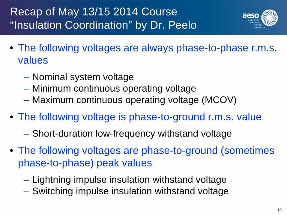
• Over-Voltage – Any voltage that exceeds the MCOV. Often expressed in p.u. with reference to the peak phase-to-ground maximum voltage
1 p.u. = MCOV × 2 ÷ 3
• Critical flashover (CFO) voltage – A voltage with a given waveform that causes flashover on 50% of all tests
The breakdown of most insulation materials is basically probabilistic in nature. It often follows a normal (Gaussian) distribution. The CFO is simply the mean value of the statistical distribution.

Recap of May 15/17 2012 Course “Understanding Grounding” by Dr. Xu
18
• If-1φ can be 3
𝐾+2 times of If-3φ
• TOV can be 3(1+𝐾+𝐾2)
𝐾+2 times of rated V (MCOV)
Where 𝐾 = 𝑍0𝑍1
When 𝐾 < 3 Effectively grounded (as per IEEE and IEC)
At any point of a network,

Recap of May 13/15 2014 Course “Insulation Coordination” by Dr. Peelo
19
• Representative over-voltage (Urp) – A voltage that produces the same dielectric effect on insulation as over-voltages of a given class occurring in services (There are up to four representative over-voltages in a power system)
• Coordination withstand voltage (Ucw) – for each class of voltage, the value of the withstand voltage of the insulation configuration in actual service conditions, that meets the performance criteria (Adjusted Urp considering inaccuracy of initial data)
• Required withstand voltage (Urw) – the test voltage that the insulation must withstand in a standard withstand test to ensure that the insulation meets the performance criteria when subjected to a given class of over-voltages in actual service conditions and for the whole service duration (Adjusted Ucw considering the difference between standard test conditions and real-life operating conditions)
Recap of May 13/15 2014 Course “Insulation Coordination” by Dr. Peelo
20
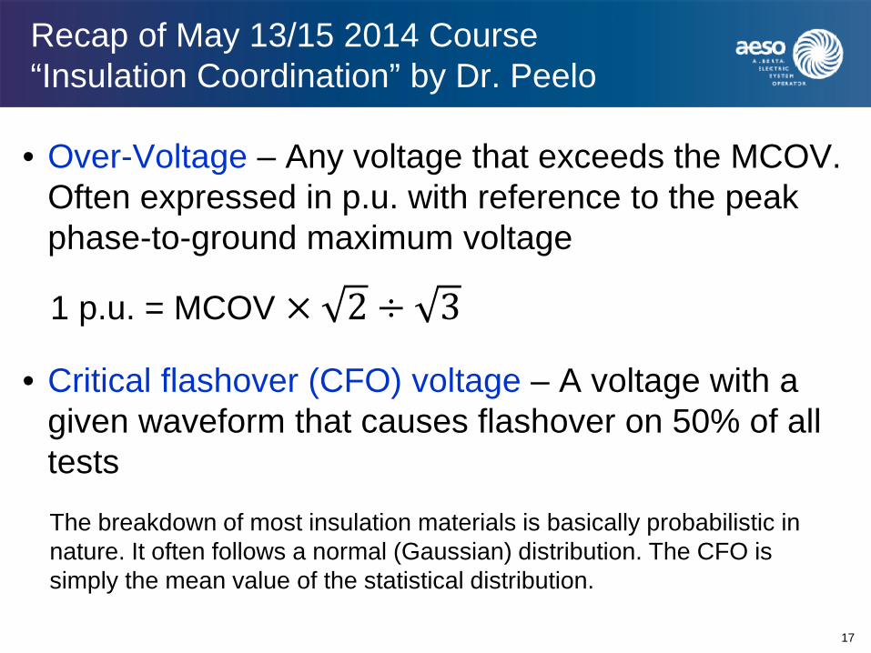
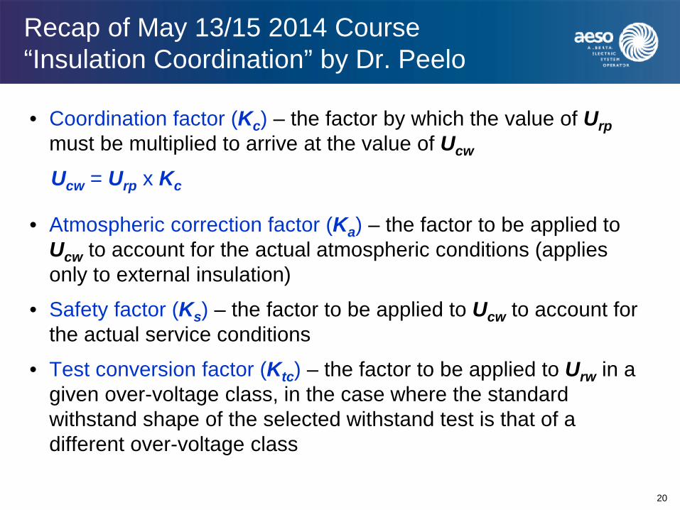
• Coordination factor (Kc) – the factor by which the value of Urp must be multiplied to arrive at the value of Ucw
Ucw = Urp x Kc
• Atmospheric correction factor (Ka) – the factor to be applied to Ucw to account for the actual atmospheric conditions (applies only to external insulation)
• Safety factor (Ks) – the factor to be applied to Ucw to account for the actual service conditions
• Test conversion factor (Ktc) – the factor to be applied to Urw in a given over-voltage class, in the case where the standard withstand shape of the selected withstand test is that of a different over-voltage class
Recap of May 13/15 2014 Course “Insulation Coordination” by Dr. Peelo
21
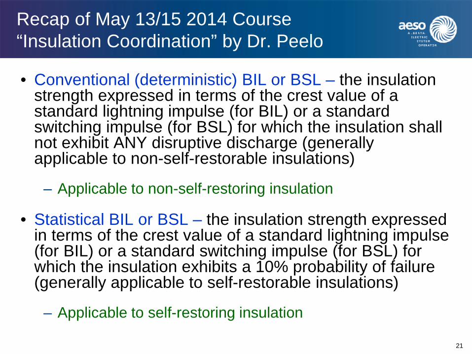
• Conventional (deterministic) BIL or BSL – the insulation strength expressed in terms of the crest value of a standard lightning impulse (for BIL) or a standard switching impulse (for BSL) for which the insulation shall not exhibit ANY disruptive discharge (generally applicable to non-self-restorable insulations)
– Applicable to non-self-restoring insulation
• Statistical BIL or BSL – the insulation strength expressed in terms of the crest value of a standard lightning impulse (for BIL) or a standard switching impulse (for BSL) for which the insulation exhibits a 10% probability of failure (generally applicable to self-restorable insulations)
– Applicable to self-restoring insulation

Recap of May 13/15 2014 Course “Insulation Coordination” by Dr. Peelo
22
Basic Impulse Level (BIL or BSL) The crest voltage of a standard wave (either a 1.2/50 impulse or a 250/2500 impulse) that will not (or in 90% of the tests, will not) cause a flashover of the insulation is referred to as “Basic Impulse Level or BIL”
The insulation strength of equipment as tested should be equal or above the BIL as specified in an AESO’s Functional Spec
1.2/50
250/2500
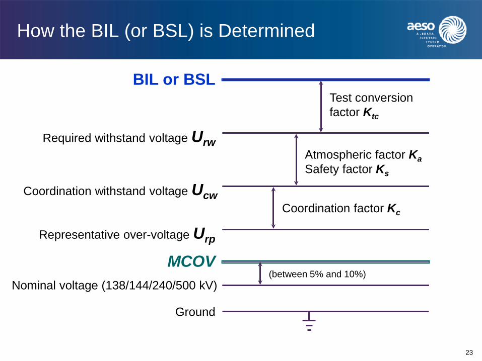
How the BIL (or BSL) is Determined
23
Ground
Representative over-voltage Urp
MCOV
Coordination withstand voltage Ucw
Required withstand voltage Urw
BIL or BSL Test conversion factor Ktc
Atmospheric factor Ka Safety factor Ks
Coordination factor Kc
(between 5% and 10%) Nominal voltage (138/144/240/500 kV)

Recap of May 13/15 2014 Course “Insulation Coordination” by Dr. Peelo
24
Standard lightning impulse voltage waveform Standard switching impulse voltage waveform
Temporary over-voltage Very fast front short duration over-voltage
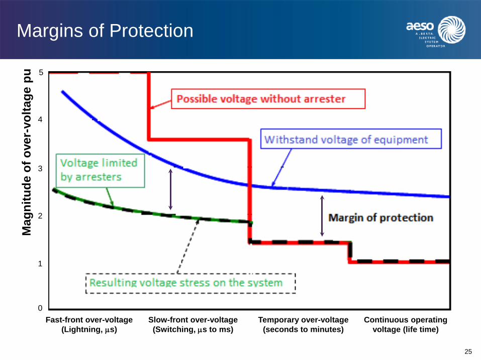
Margins of Protection
25
Mag
nitu
de o
f ove
r-vo
ltage
pu
Fast-front over-voltage (Lightning, µs)
0
2
1
3
4
5
Slow-front over-voltage (Switching, µs to ms)
Temporary over-voltage (seconds to minutes)
Continuous operating voltage (life time)

Recap of May 13/15 2014 Course “Insulation Coordination” by Dr. Peelo
26

Recap of May 13/15 2014 Course “Insulation Coordination” by Dr. Peelo
27
Temporary Over Voltage (TOV) • An oscillatory phase-to-ground or phase-to-phase over-voltage, at a
given location and of relatively long duration (1s to 10s), is undamped or only weakly damped
• TOV level establishes the rating of surge arrestors • The general rule is that surge arresters should not activate at TOV but
will activate when experiencing higher voltages
Major causes of TOV • Load rejection • Ground faults • Resonance phenomena or harmonics • Line energization/deenergization
Duration of TOV • Typically 1s to 10s (or minutes in extreme cases)

Surges and Transient Over-Voltages
28
A short-duration highly damped, oscillatory or non-oscillatory over-voltage, having a duration of a few milliseconds or less. Transient over-voltage is normally classified as one of the following types
• Slow front
• Fast front
• Very fast front
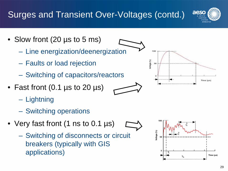
Surges and Transient Over-Voltages (contd.)
29
• Slow front (20 µs to 5 ms) – Line energization/deenergization
– Faults or load rejection
– Switching of capacitors/reactors
• Fast front (0.1 µs to 20 µs) – Lightning
– Switching operations
• Very fast front (1 ns to 0.1 µs) – Switching of disconnects or circuit
breakers (typically with GIS applications)

Class and Shapes of Over-Voltage and Tests
30 Source: IEC 60071-2

Over-Voltages Amplitudes
31
Power-Frequency Temporary Over-Voltage • Generally ≤ 10s
SLG faults <1.5 pu Ferranti effect <1.3 pu Load rejection < 1.4 pu Resonance > 2 pu Energization/re-energ. < 1.5 pu Stuck breaker pole < 2 pu
Lightning Over-Voltage • Fast front 1-6 µs > 5 pu
Tail @ 50%: 50 µs
Switching Over-Voltage • Slow front 30-300 µs
Tail @ 50%: 100-2000µs Energizing lines 1.5-2 pu Re-energizing lines 3-3.4 pu Switching no-load xformr > 2 pu Switching reactor > 2 pu Switching capacitors 1.5-2 pu Fault interruption 1.5 pu
Typical Insulation Coordination Studies
32
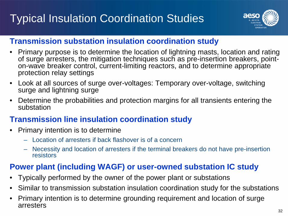
Transmission substation insulation coordination study • Primary purpose is to determine the location of lightning masts, location and rating
of surge arresters, the mitigation techniques such as pre-insertion breakers, point-on-wave breaker control, current-limiting reactors, and to determine appropriate protection relay settings
• Look at all sources of surge over-voltages: Temporary over-voltage, switching surge and lightning surge
• Determine the probabilities and protection margins for all transients entering the substation
Transmission line insulation coordination study • Primary intention is to determine
– Location of arresters if back flashover is of a concern – Necessity and location of arresters if the terminal breakers do not have pre-insertion
resistors
Power plant (including WAGF) or user-owned substation IC study • Typically performed by the owner of the power plant or substations • Similar to transmission substation insulation coordination study for the substations • Primary intention is to determine grounding requirement and location of surge
arresters
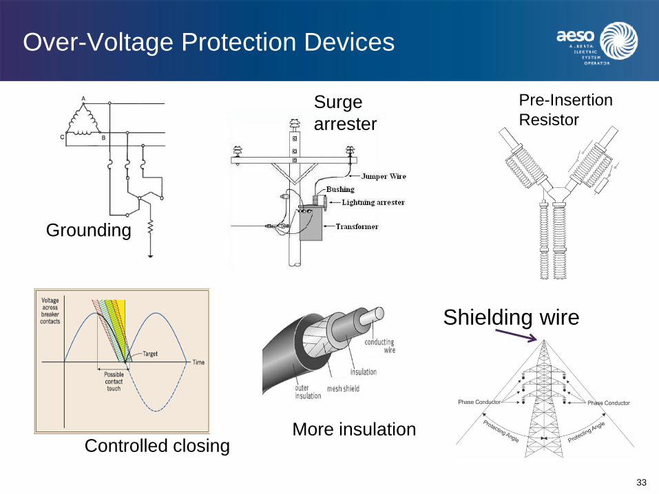
Over-Voltage Protection Devices
33
Surge arrester
Pre-Insertion Resistor
Controlled closing
Grounding
More insulation
Shielding wire

Characteristics of SiC and ZnO Arresters
34
Characteristics of different surge arresters

Selection of Surge Arresters
35
• Location • Maximum continuous operating voltage • Amplitude and shape of over-voltages
• Nominal discharge current
• Residual voltage at the nominal discharge current
• Energy absorbing capability (Arrester class) • Surge impedance and/or capacitance of the
protected equipment
Selection of Surge Arresters
36
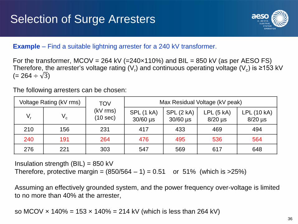
Example – Find a suitable lightning arrester for a 240 kV transformer. For the transformer, MCOV = 264 kV (=240×110%) and BIL = 850 kV (as per AESO FS) Therefore, the arrester’s voltage rating (Vr) and continuous operating voltage (Vc) is ≥153 kV (= 264 ÷ 3) The following arresters can be chosen:
Voltage Rating (kV rms) TOV (kV rms) (10 sec)
Max Residual Voltage (kV peak)
Vr Vc SPL (1 kA) 30/60 µs
SPL (2 kA) 30/60 µs
LPL (5 kA) 8/20 µs
LPL (10 kA) 8/20 µs
210 156 231 417 433 469 494
240 191 264 476 495 536 564
276 221 303 547 569 617 648
Insulation strength (BIL) = 850 kV Therefore, protective margin = (850/564 – 1) = 0.51 or 51% (which is >25%) Assuming an effectively grounded system, and the power frequency over-voltage is limited to no more than 40% at the arrester, so MCOV × 140% = 153 × 140% = 214 kV (which is less than 264 kV)

Procedure for Insulation Coordination
37
Determination of representative over-voltage Urp
Determination of coordination withstand voltage Ucw
Determination of required withstand voltage Urw
Rated or standard insulation level Uw
• Transient analysis & simulation • Origin and level of over-voltages • Statistical distribution of over-voltages • Protective level of arresters • Insulation characteristics • Determine contamination severity • Verification of data and assumptions • Determine coordination factor Kc
• Determine altitude correction factor Ka • Determine safety factor Ks
• Determine test conversion factor Ktc • Determine level and range of Uw (for
both internal and external)
Kc
Ka Ks
Ktc

Differences between IEEE and IEC
38
• Both IEEE 1313 and IEC 60071 are excellent reference standards • Procedures and methodologies in both standards are same or similar • In many cases IEEE 1313 cites directly IEC 60071 recommendations • The differences are minor and subtle
IEEE 1313 IEC 60071
Nomenclature BIL, SIL LIWV, SIWL, ACWV
Detail Tend to be concise Detailed with more examples
Performance criteria Generally more “aggressive”
Generally more “conservative”
MCOV ≥ 15 kV ≥ 1 kV

Typical Nominal, Minimum, MCOV and BIL Values in AESO’s Functional Specification
39
Nominal (kV)
Minimum (kV)
MCOV (kV)
BIL (kV)
25 23 28 150
69 62 79 350
138 124 152 650
144 130 155 650
240 216 264 1050
500 475 550 1800
Insulation Coordination for Transmission Lines
40
Transmission Line Insulation Coordination Involves
• Shielding angle of the shielding wire • Clearance of conductors • Selection of the type and length of insulators
Keep in Mind
• Shielding Failure Flashover Rate (SFFOR) and Back Flashover Rate (BFR) are two typical design criteria – typical SFFOR is 0.05 f/100km-yr and BFR is 1 f/100km-yr
• The higher the tower and voltage, the smaller the shielding angle • BFR impacts substation insulation requirements • Contamination influences creepage distance (mm/kV) and consequently
the number of insulator units • Generally, from an insulation perspective, transmission line reliability
performance is 10% of substation reliability criterion

Insulation Coordination for Substations
41
Substation Insulation Coordination Involves
• Determination of BILs for major equipment or equipment group • Location of shielding masts and/or shielding wires • Clearance of conductors • Surge arresters – Rating, number & locations
Keep in Mind
• MTBF (and BFR) determine if line-entrance arresters are required • Transformers and cables should always be primary concerns • Protective margin is generally for non-self-restoring insulation • Cost of equipment failure generally determines sequence of failure • Gap configuration can change CFO level by ±30% • Lightning flash can be multiple strokes – longitudinal insulation • There may be back-and-forth calculations/adjustments required

Protection and Insulation Coordination of Substation Components
42
Substation Type
• Air-insulated substation • Gas-insulated substation
Major Equipment
• Transformers
• Circuit breakers
• CTs and PTs
• Capacitors/Reactors
• Cables

Insulation Coordination between T and D
43
General Principles
• Similar to protection coordination between transmission and distribution
• Should a surge result in insulation breakdown, it should generally be on the distribution system first
• Interruptions to consumers are more confined and
localized, i.e., fewer customers impacted per event
• Distribution utilities are generally closer to the failed equipment – faster response

Typical BIL Levels of Distribution Class & Power Class
44
Voltage (rms kV)
Distribution Class BIL (kV)
Power Class BIL (kV)
5 60 75
8.7 75 95
15 95 110
25 110 150
34.5 150 200
72 250 350
Insulation Coordination between T and G
45
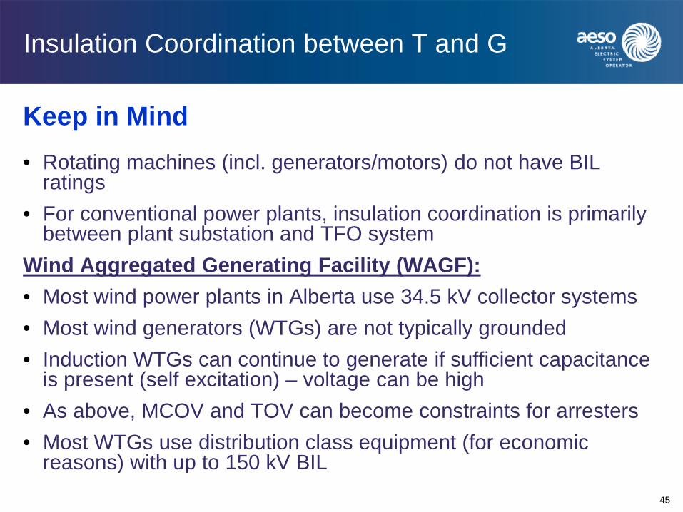
Keep in Mind • Rotating machines (incl. generators/motors) do not have BIL
ratings • For conventional power plants, insulation coordination is primarily
between plant substation and TFO system Wind Aggregated Generating Facility (WAGF): • Most wind power plants in Alberta use 34.5 kV collector systems • Most wind generators (WTGs) are not typically grounded • Induction WTGs can continue to generate if sufficient capacitance
is present (self excitation) – voltage can be high • As above, MCOV and TOV can become constraints for arresters • Most WTGs use distribution class equipment (for economic
reasons) with up to 150 kV BIL
Insulation Coordination between Transmission Lines and Substations
46
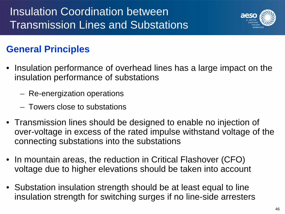
General Principles
• Insulation performance of overhead lines has a large impact on the insulation performance of substations
– Re-energization operations
– Towers close to substations
• Transmission lines should be designed to enable no injection of over-voltage in excess of the rated impulse withstand voltage of the connecting substations into the substations
• In mountain areas, the reduction in Critical Flashover (CFO) voltage due to higher elevations should be taken into account
• Substation insulation strength should be at least equal to line insulation strength for switching surges if no line-side arresters

Things to Remember in Insulation Coordination
47
• The TFOs and Market Participants, not the equipment manufacturers, are responsible for insulation coordination studies
• There is nothing more important than “knowing your system better”
• There is not always a “single best solution” to insulation coordination
• Back-and-forth calculations and adjustments are often needed in insulation coordination studies
• Deterministic approach should always be applied to non-self-restoring equipment
• Statistical approach can be applied to self-restoring equipment
• Surge arresters are generally not used to limit temporary over-voltages (TOVs)

Things to Remember in Insulation Coordination (cont’d)
48
• Basically, the basic impulse level (BIL) is equal to the Representative Over-Voltage Urp with many correction factors on top
• Insulation coordination is both an art and science, and is often an economic decision. Many parameters or requirements are conflicting in reality. Example – To reduce BFR of a transmission line Option: increase conductor spacing and insulator units larger tower higher cost and increased surge impedance increased BFR
• Power system insulation is an ever-evolving field. More research needs to be done to more fully understand the transient behavior of lightning, switching surges, etc. IEEE 1243 – Guide for Improving the Lightning Performance of Transmission Lines says – The methods for estimating the lightning performance of transmission lines show
several approaches to a real‐life engineering problem that is ill‐defined. Precise constants are rarely known and are often not really constant, input data is difficult to describe mathematically except in idealized ways

THANK YOU
Questions?

Insulation Coordination in the Alberta Interconnected Electric System
Part 2
Ligong Gan, P.Eng. Transmission Engineering & Performance Alberta Electric System Operator (AESO)
2
APIC Insulation Coordination – Agenda
• AESO’s role in transmission system insulation coordination
• Evolution of BIL requirements in Alberta
• Insulation Requirements in AESO’s Functional Specifications
• Thoughts on Possible Future Changes to Current BIL Levels
• Q&A
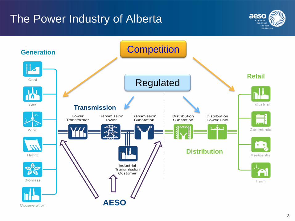
The Power Industry of Alberta
3
Distribution
Retail
Transmission
Generation Competition
Regulated
AESO
Power Industry Structure in Alberta
Electric Utilities Act
Market Surveillance Administrator
(MSA)
Balancing Pool
Alberta Utilities Commission (AUC)
Transmission Facility Owners
Distribution Facility Owners Retailers
Independent System
Operator (AESO)
Minister of Energy (Appoints AESO Board Members, MSA & AUC Chair)
Generators
4
Presenter
Presentation Notes
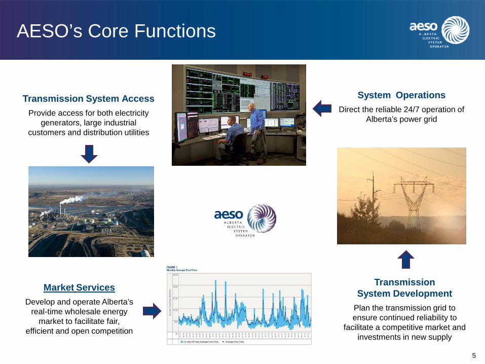
AESO’s Core Functions
5
System Operations Direct the reliable 24/7 operation of
Alberta’s power grid
Transmission System Development
Plan the transmission grid to ensure continued reliability to
facilitate a competitive market and investments in new supply
Transmission System Access Provide access for both electricity
generators, large industrial customers and distribution utilities
Market Services Develop and operate Alberta’s
real-time wholesale energy market to facilitate fair,
efficient and open competition

Alberta’s Bulk Transmission System 240-500 kV (now and near future)
Virtually all 240 kV lines
The KEG loop (500 kV)
Two 500 kV HVDC lines between Edmonton area and Calgary area
Two 500 kV AC lines planned from Edmonton area to Fort McMurray area
One 500 kV AC interconnection to British Columbia
One 240 kV interconnection to Montana
One 150 MW (HVDC) interconnection to Saskatchewan
6
Dover
Ellerslie Genesee Keep - hills
Sundance
Wabamun Clover Bar
Sheerness
Sarcee Langdon
Deerland
Battle River
Brazeau
McMillan
Milo West Brooks
Metiskow
Red Deer
Sagitawah
Louise Creek
Mitsue
Little Smoky
Wesley Creek
Bickerdike
Benalto
Beddington
Peigan
N . Lethbridge
Marguerite Lake
Cordel
Anderson
Josephburg
Jenner
Empress E . Calgary
Goose Lake
L eismer Christina
Lake
Conklin
Janet
Bowmanton
Whitla
‘ MATL ’
Etzikom Coulee
Chapel Rock
Filder Windy Flats
Stavely SC 1
SS - 65
Foothills
Shepard
Crossing
Bennett
Cassils
Sunnybrook
H e art Lake
Heathfield
Heartland
Hansman Lake
Pemukan
Lanfine
Thickwood
Livock
Newell
SC 2
Whitefish Lake
Brintnel l
Presenter
Presentation Notes

Alberta’s Existing Transmission System
Voltage Substations (energized)
Xmission Lines (km) (energized)
TFO Customer TFO Customer
69/72 kV 70 11 2,246 21
138/144 kV 403 57 12,824 282
240 kV 101 23 10,361 223
500 kV 8 602
Note: Circuit length (km) includes both overhead lines and underground cables
Presenter
Presentation Notes
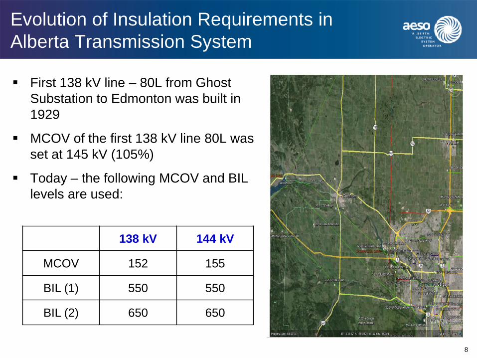
Evolution of Insulation Requirements in Alberta Transmission System
8
First 138 kV line – 80L from Ghost Substation to Edmonton was built in 1929
MCOV of the first 138 kV line 80L was set at 145 kV (105%)
Today – the following MCOV and BIL levels are used:
138 kV 144 kV
MCOV 152 155
BIL (1) 550 550
BIL (2) 650 650

Evolution of Insulation Requirements in Alberta Transmission System
9
First 230 kV line, between Wabamun and Sarcee 42S was built in 1961
MCOV of the first 230 kV line was set at 242 kV
Wabamun had to operate at 253 kV in order to maintain acceptable voltage at Sarcee
Because of the circuit length (>450 km), special equipment with MCOV of 264 kV was installed at Wabamun
The system was then classified as “240 kV nominal voltage”
BIL levels of 900 kV and 1050 kV were chosen, assuming a grounding factor of 1.4

Evolution of Insulation Requirements in Alberta Transmission System
10
In 1986, first 500 kV tie-line 1201L, between Langdon and Cranbrook (B.C.), was built
In 1982, first intra-Alberta 500 kV line 1202L, between Keephills and Ellerslie, was built but operated at 240 kV
In 2010, 1202L re-energized at 500 kV
MCOV of 1201L/1202L was set at 550 kV
BIL of 1425/1550/1800 kV chosen for substations 89S/320P/102S
Since around 2011, 1550/1800 kV became BIL levels for 500 kV system
Dover
Ellerslie Genesee Keep - hills
Sundance
Wabamun Clover Bar
Bowmanton
Whitla
‘ MATL ’
Etzikom Coulee
Chapel Rock
Filder Windy Flats
Stavely SC 1
SS - 65
Foothills
Shepard
Crossing
Bennett
Cassils
Sunnybrook
H e art Lake
Heathfield Heartland
Hansman Lake
Pemukan
Lanfine
Thickwood
Livock
Newell
SC 2
Whitefish Lake
Brintnel l
Existing 240 kV Existing 500 kV
Thermal Plant Hydro Plant
AIES Transmission System
500 / 240 kV System Overview
Future 240 kV Future 500 kV Future 500 kV HVDC
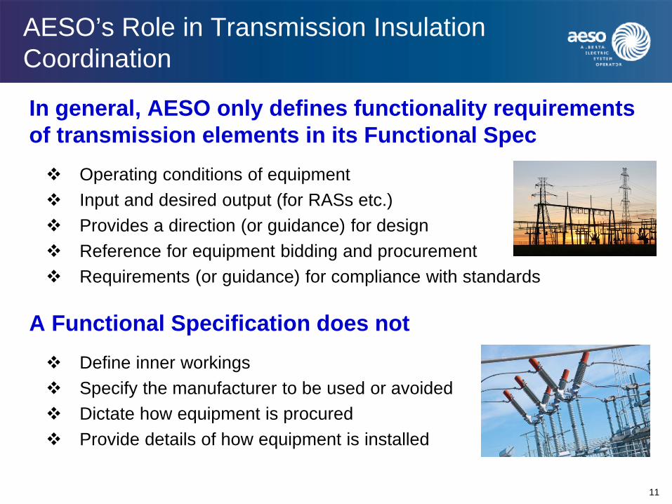
AESO’s Role in Transmission Insulation Coordination
11
In general, AESO only defines functionality requirements of transmission elements in its Functional Spec Operating conditions of equipment Input and desired output (for RASs etc.) Provides a direction (or guidance) for design Reference for equipment bidding and procurement Requirements (or guidance) for compliance with standards
A Functional Specification does not Define inner workings Specify the manufacturer to be used or avoided Dictate how equipment is procured Provide details of how equipment is installed

AESO’s Role in Transmission Insulation Coordination (cont’d)
12
Typically, AESO’s Functional Spec contains
Purpose Interpretation and Variances Project Overview Scope of work
Standards Scope of work for TFO and Market Participant
Transmission System Operating Characteristics Normal operating levels and constraints Emergency operating requirement
Appendices Single line diagrams for substation configuration and SCADA
requirements

Some Relevant Rules & Standards
13
• ISO rule 502.1 – Wind Aggregated Generating Facilities Technical Requirements Section 21 provides lightning surge protection requirements for the collector stations, and between collector substation and transmission line
• ISO rule 502.2 – Bulk Transmission Line Technical Requirements Specifies the standards to be used in setting electrical clearances, the conditions under which an insulation study is required, and the minimum insulation levels of a bulk transmission line The Information Document (ID) further provides detailed explanation as to how insulation coordination is conducted, and the recommended BIL levels
• Generation & Load Interconnection Standard 2006 Section 2.3 sets out the general requirements for insulation studies and the specific IEEE standard (P998) to be employed
• ARS FAC-001-AB – Facility Connection Requirements Section R2.6 requires that the AESO’s interconnection requirement or project’s Functional Spec must address insulation and insulation coordination

AESO’s Philosophy on Insulation Coordination
14
• AESO specifies rules & standards which set out minimum technical requirements
• AESO provides minimum BIL levels without distinguishing
– between BIL & BSL – between conventional & statistical
• TFOs and market participants are required to perform any and all insulation coordination studies and determine appropriate insulation levels
• TFOs and market participants are required to coordinate with each other in setting equipment insulation levels

AESO Rule 502.2 – Transmission Lines
15
• Section 14(2) – Shield wires must be installed on 138/240/500 kV AC or ±500 kV DC bulk transmission lines
• Section 14(3) – Number and positioning of the shield wires must be so as to produce lightning flashover rates that are consistent with all reliability requirements of the lines
• Section 17(5) – Electrical clearances for use with the wind pressure values of Table 3 must be determined from the application of the methodology outlined in IEEE Standard 1313.2 “The Application of Insulation Coordination”, for transmission line phase to ground switching over voltages
AESO Rule 502.2 – Transmission Lines
16
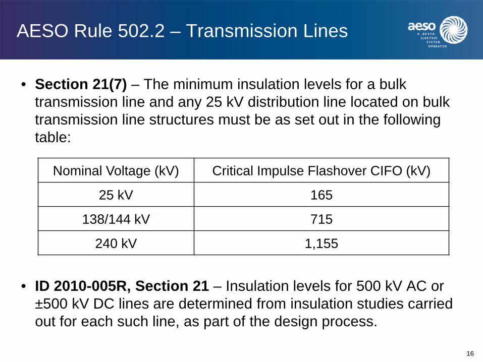
• Section 21(7) – The minimum insulation levels for a bulk transmission line and any 25 kV distribution line located on bulk transmission line structures must be as set out in the following table:
• ID 2010-005R, Section 21 – Insulation levels for 500 kV AC or ±500 kV DC lines are determined from insulation studies carried out for each such line, as part of the design process.
Nominal Voltage (kV) Critical Impulse Flashover CIFO (kV)
25 kV 165
138/144 kV 715
240 kV 1,155

AESO Rule 502.2 – Transmission Lines
17
• ID 2010-005R, Section 21 – 25 kV insulation requirement applies only to those 25 kV distribution lines placed on bulk transmission line structures. 502.2 recognizes the need for insulation coordination between circuits of different voltages located on common structures
• ID 2010-005R, Section 21 – Insulation levels for 500 kV AC or ±500 kV HVDC lines are determined from insulation studies carried out for each such line, as part of the design process. Hence, 502.2 does not include insulation levels for 500 kV class lines

AESO Functional Specification
18
In the “Project Scope” section:
• (the legal owner of the transmission facility) shall complete insulation coordination studies and coordinate with the market participant as required to establish appropriate insulation levels
• Undertake insulation, grounding, protection and communication studies as necessary to accommodate the proposed system additions and modifications
AESO Functional Specification
19
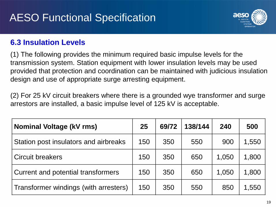
6.3 Insulation Levels (1) The following provides the minimum required basic impulse levels for the transmission system. Station equipment with lower insulation levels may be used provided that protection and coordination can be maintained with judicious insulation design and use of appropriate surge arresting equipment.
(2) For 25 kV circuit breakers where there is a grounded wye transformer and surge arrestors are installed, a basic impulse level of 125 kV is acceptable.
Nominal Voltage (kV rms) 25 69/72 138/144 240 500
Station post insulators and airbreaks 150 350 550 900 1,550
Circuit breakers 150 350 650 1,050 1,800
Current and potential transformers 150 350 650 1,050 1,800
Transformer windings (with arresters) 150 350 550 850 1,550

Thoughts on Possible Future Changes to Current BIL Levels
20
• Should we split the current basic insulation levels into BIL and BSL levels?
• In some 500 kV projects, it has been suggested that the BIL level for the 500/240 kV autotransformers be set at 1425 kV for lower cost and easier transportation
• Should we create a new nominal voltage level of 260 kV with MCOV of 286 kV (or 275 kV)?
• Should we raise the current BIL for 240/260 kV transformers from 850 kV to 900 kV (or higher)?
• Should we differentiate GIS from AIS equipment, especially for 500 kV equipment, on the BIL levels?
• Any other from you?

Upcoming AESO Rule for Substations – 502.11
21
• The AESO is now in the process of developing a Substation Rule (502.11) which sets out the minimum technical requirements respecting design, engineering and construction of (new) transmission substations
• Insulation coordination and grounding will be a major part of Rule 502.11
• Proposed Process (2015-2016) – Industry Workgroup (WG)
– Recommendation paper to WG & stakeholders
– Draft and post Rule for comments from industry
– Filing of Rule 502.11 with AUC

THANK YOU
Questions?

University of Alberta
Over-Voltages and the
Distribution System
Thomas C. Hartman, P.Eng.
APIC – Professional Development
May 12 & 14, 2015

University of Alberta 1
Discussion Outline - OVERVIEW
• The Origin and Shapes of Distribution System Surges
• Insulation Systems – And How They Go Bad
• Where Surges Matter – And What They Do – Overhead Systems
– Underground Systems
• Distribution Surge Arresters – Design and Application
• Reality Check
• Q & A
NOTE: References are in parenthesis - (xx)

University of Alberta 2
Disclaimer
I will mention many companies during this presentation.
Please keep in mind:
1 – I have NO financial interest or otherwise in any of the
companies I mention
2 – I work for ATCO Electric Distribution and that is my only
source of income
3 – This presentation is my opinion only and does not
necessarily reflect ATCO policy, practices, or standards
4 – I expect that you will use this presentation for illustrative
purposes only. Any arrester applications you design shall
be based on your own professional judgement
University of Alberta 3
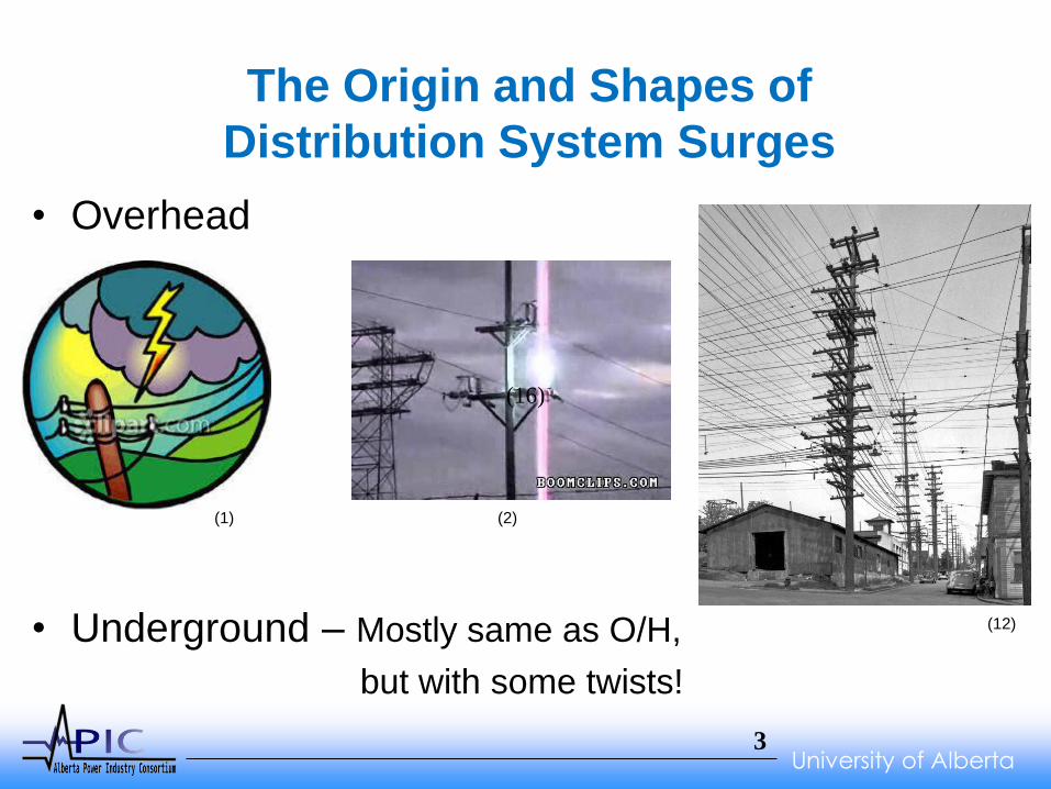
The Origin and Shapes of
Distribution System Surges
• Overhead
• Underground – Mostly same as O/H,
but with some twists!
(16)
(1) (2)
(12)

University of Alberta 4
What is a Surge?
Surge
• IEEE Std 100: “A transient wave of current, potential, or power in an electric circuit. Note: The use of this term to describe a momentary overvoltage consisting in a mere increase of the mains voltage for several cycles is deprecated. See also: swell.”
Temporary Overvoltage (TOV)
• IEEE Std 100: “. An oscillatory overvoltage, associated with switching or faults … and/or nonlinearities … of relatively long duration, which is undamped or slightly damped.”

University of Alberta 5
TOV
It is NOT a Surge!
• Accidental Grounding - Leg of Delta
• Loss of Neutral
• Fault Conditions
• Comingling
“When Overbuild Meets Underbuild”
Surge arresters provide a simple solution to a complex overvoltage
problem
Daniel J. Ward, Dominion Virginia Power
T&D World Magazine - Mar 1, 2011

University of Alberta 6
World Ground Flash Density
www.arresterworks.com/resources/calculator_images/GFD_World.jpg
University of Alberta 7
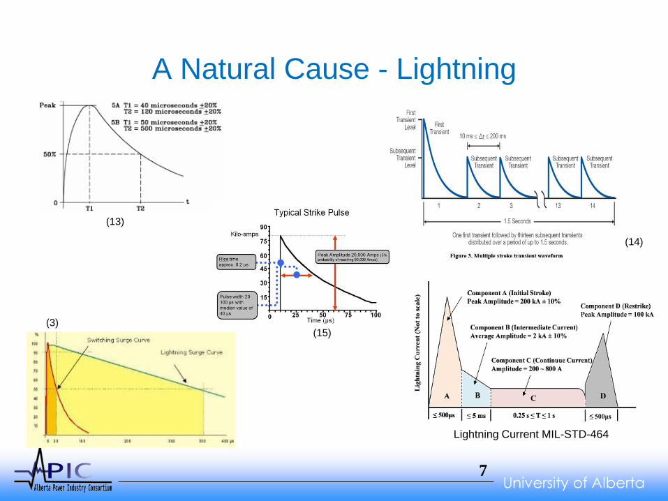
A Natural Cause - Lightning
(13)
Lightning Current MIL-STD-464
(14)
(3) (15)
University of Alberta 8
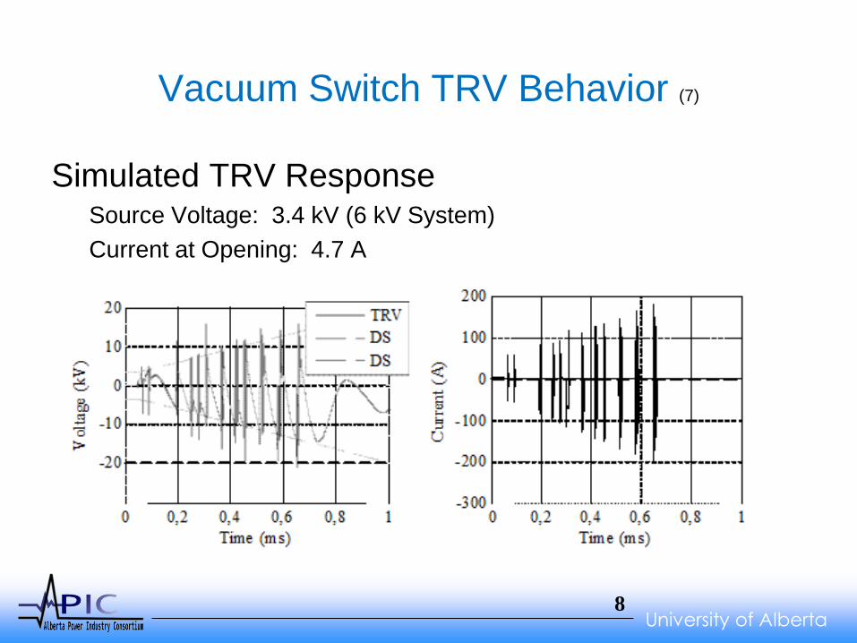
Vacuum Switch TRV Behavior (7)
Simulated TRV Response Source Voltage: 3.4 kV (6 kV System)
Current at Opening: 4.7 A

University of Alberta 9
Shunt Capacitors
(5)
Effect of switching re-strikes on capacitor voltage
(6)

University of Alberta 10
Current Limiting Fuse Operation
(11)
University of Alberta 11
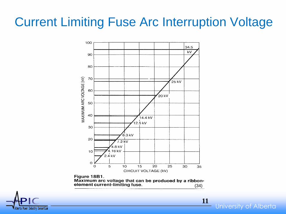
Current Limiting Fuse Arc Interruption Voltage
(34)

University of Alberta 12
Other Surge Waveforms
Switching Surge (36)
(37)
(38)

University of Alberta 13
Surges and Their Waveforms
Just So YOU Know…
Lead Length can ADD up to 1500 Volts/Foot
Lead length is the physical wire distance between the
Apparatus and the Line Side of the Surge Arrester
PLUS (+)
The Line Length from the Ground of the Surge
Arrester to the Ground of Apparatus
AND for the Love of Goodness,
Please Don’t COIL the Leads!!!
University of Alberta 14
Insulation Systems
And How They Go Bad
If we lived in a perfect world, our insulation systems
would last forever. But…
We don’t.
All Insulation Systems are Doomed from the Start!
• Embedded Manufacturing Defects
• Environmental Contamination
• Shipping and Handling
• “Some” Field Assembly Required (32)
University of Alberta 15
Insulation Systems– How Do They Fail?
External Sources
• Physical Damage – “Rocks and Rifles”, External Arc
• Contamination – Farming, Exhaust, Salt, etc.
Internal Sources
• Water Ingress
• Arcing under Oil or SF6
• “Built-In” Defects – Either from Vendor or Customer
University of Alberta 16
Insulation Systems
Contamination and Built-In Defects
Contamination – Surge Arresters Really Won’t Help
• The Failure Mechanisms Associated with
Contamination are Active at 60 Hz System Voltage
“Built-In” Defects – Surge Arresters May Help
• If the Failure Mechanism is Triggered by a Surge,
then a Surge Arrester will Delay the Trouble
• If the “Built-In’ Defect is Active at System Voltage,
then a Surge Arrester Won’t Help.

University of Alberta 17
Insulation Systems – Failure Triggers
Contamination
• Dry Band Arcing is the Beginning of the End
“Built-In” Defects
• It is All About Capacitance, Dielectric
Constants, and Dielectric Strength
• C = (k*e0*A)/d
where k: Air =1, Silicone = 4, EPDM = 2.6
Glass = 6, Polyethylene = 2.25, Porcelain = 6
Which Equals an Evil Voltage Divider

University of Alberta 18
Ceramic / Glass
• One Tough Insulation System!
• Can Last a Century or More
• Surges / Flashovers are Generally Benign
Failure Mechanisms
• Slow Clearing Times Crack Ceramic/Glass
• Susceptible to Point Pressures Resulting in Crack
Propagation
• Pin Threads (lead/nylon)
• Ice Expansion Forms Cracks
• External Contamination / Cleaning

University of Alberta 19
Polymers
Organic/Semi-Organic System
• Manufacturing Process
Sensitive
Failure Mechanisms
• Embedded
Manufacturing/Material Defect
• If Small Enough, the Defect
Lays Dormant Longer
• Surges Reduce PD Inception
Levels
• Ultimate Demise of Insulator (30)
(31)
University of Alberta 20
Dielectric Fluid – Oil (29)
1. Oxidation: Oxidation is the most common cause of oil deterioration, which is the reason
that transformer manufacturers are careful to seal the transformer from the atmosphere.
2. Contamination: Moisture is the main contaminant. Its presence can react with the oil in the
presence of heat. It also lowers the dielectric properties of the insulating oil.
3. Excessively high temperature: Excessively high heat will cause decomposition of the oil
and will increase the rate of oxidation. The best way to avoid excessive heat is to avoid
overloading the transformer.
4. Corona discharges: Arcing and localized overheating can also break down the oil,
producing gases and water, which can lead to the formation of acids and sludge.
5. Static electricity: The existence of an insulating fluid flowing past an insulating solid
(paper), results in charge separation at the interface of the two materials. Physically, these
charges separate at the interface of the oil and paper in any transformer; thus reducing the
dielectric strength of the insulating oil. This could also cause internal flashover.
6. Furans: Furan derivatives are a measure of degradation of paper insulation. When the
paper ages, the long-chain cellulose molecules (polymers) break down in smaller fractions
and its physical strength is reduced. The degree of polymerization can be directly related to
the concentration of furan derivatives, which are formed in the oil.
University of Alberta 21
SF6 (28)
Sulfur hexafluoride (SF6) is a relatively nontoxic gas used in a number of applications for its
inert qualities. The dielectric and other physical and chemical properties related to its lack
of reactivity have led to the extensive use of SF6 as an insulating medium in switching
equipment (e.g., circuit breakers) by electric utilities. While SF6 is inert during normal use,
when electrical discharges occur within SF6-filled equipment, toxic byproducts can be
produced that pose a threat to health of workers who come into contact with them.
SF6 can decompose into byproducts when exposed to four types of electric discharges
(CIGRE1 1997)
• partial corona discharges caused by insulation defects;
• spark discharges that occur at insulation defects or during switching operations;
• switching arcs that occur in load break switches and power circuit breakers; and
• failure arcs that occur due to insulation breakdown or switchgear interruption failure.
Each discharge can result in different mixtures and concentrations of byproducts.

University of Alberta 22
Where Surges Matter ~ OVERHEAD SYSTEMS
And What They Do There
Pin Insulator
Transformer
Regulator
Capacitor
Riser Pole
On the Secondary

University of Alberta 23
At the Pin Insulator (16)
University of Alberta 24
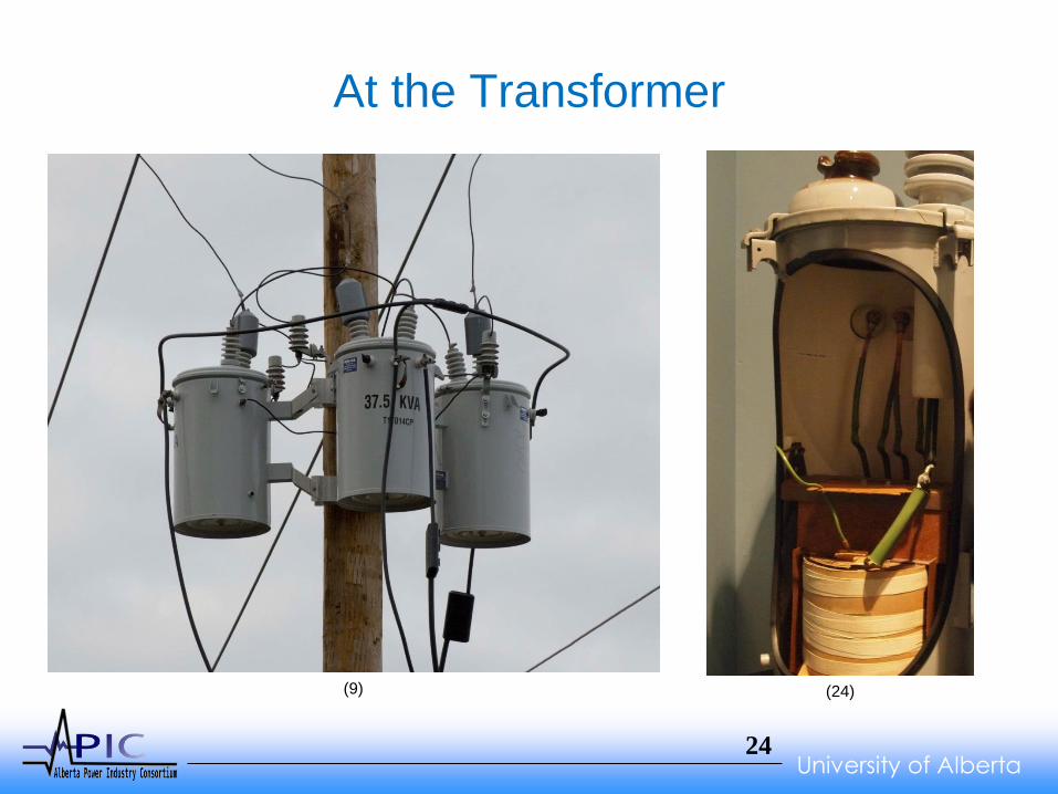
At the Transformer
(9) (24)

University of Alberta 25
At the Secondary
Transformer Secondary Protection
Surge Suppression Inc.
EATON’s Cooper Power Systems At the secondary bushing – Inside (9)

University of Alberta 26
At the Capacitor (17)
(18)
(17)

University of Alberta 27
At the Regulator
(19)
(35)

University of Alberta 28
Where Surges Matter ~ UNDERGROUND
And What They Do There
Underground Systems
• Riser Pole
• Cable
• At an “Open Point”

University of Alberta 29
At the Riser Pole
(20)
(21)
(22)

University of Alberta 30
In the Cable
(25)
(26) (26) (27)

University of Alberta 31
At an “Open Point”
(4)
(10)
University of Alberta 32
At ANY Place on your System
Just So YOU Know…
Lead Length can ADD up to 1500 Volts/Foot
Lead length is the physical wire distance between the
Apparatus and the Line Side of the Surge Arrester
PLUS (+)
The Line Length from the Ground of the Surge
Arrester to the Ground of Apparatus
AND for the Love of Goodness,
Please Don’t COIL the Leads!!!

University of Alberta 33
Distribution Surge Arresters
Design and Application
• A Very Brief History of Surge Arrester Evolution
• Explanation of Surge Arrester “Classes”
• Which Class to Use
• How Arresters Eventually Fail
• Surge Arresters have ONE Job – Protect Insulation
University of Alberta 34
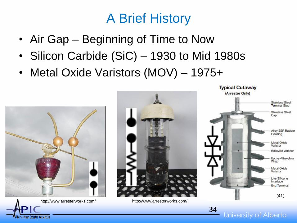
A Brief History
• Air Gap – Beginning of Time to Now
• Silicon Carbide (SiC) – 1930 to Mid 1980s
• Metal Oxide Varistors (MOV) – 1975+
http://www.arresterworks.com/ http://www.arresterworks.com/
(41)
University of Alberta 35
Differences Between Manufacturers
• None Really
• Arresters are essentially COMMODITIES
• Purchase on your preferences such as:
• Price
• Vendor Service
• Availabilities
• Vendor Preference
• Etc.
• You will likely be satisfied!
• My Preference???
University of Alberta 36
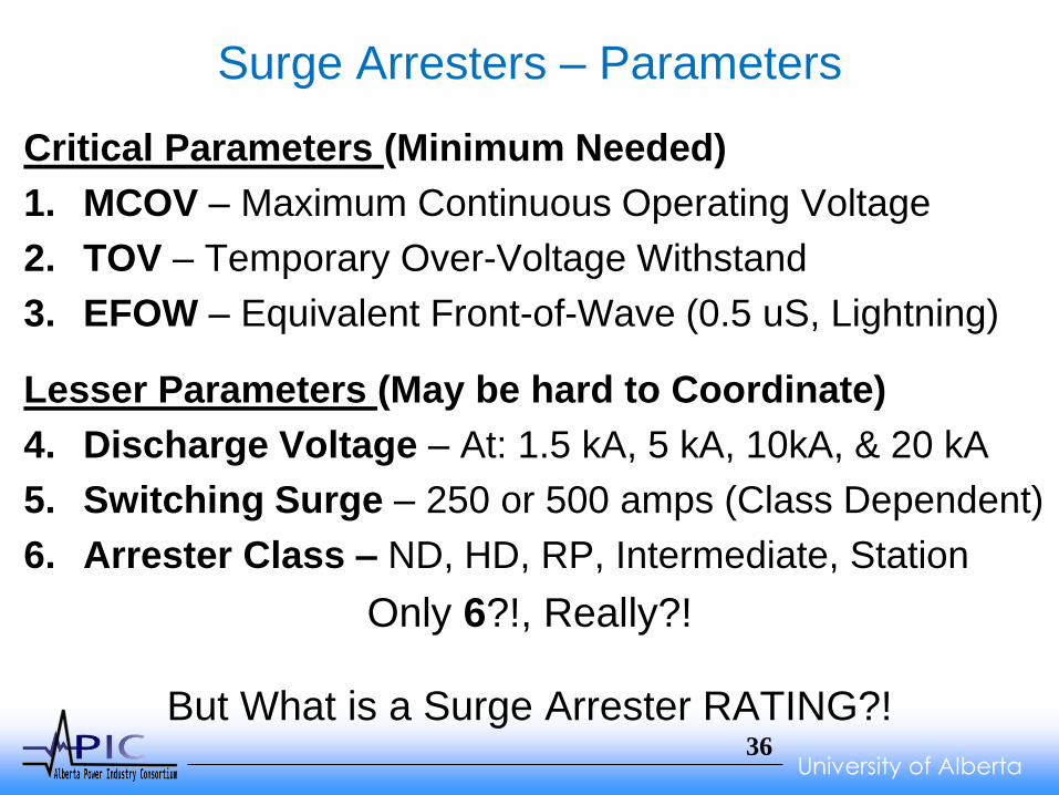
Surge Arresters – Parameters
Critical Parameters (Minimum Needed)
1. MCOV – Maximum Continuous Operating Voltage
2. TOV – Temporary Over-Voltage Withstand
3. EFOW – Equivalent Front-of-Wave (0.5 uS, Lightning)
Lesser Parameters (May be hard to Coordinate)
4. Discharge Voltage – At: 1.5 kA, 5 kA, 10kA, & 20 kA
5. Switching Surge – 250 or 500 amps (Class Dependent)
6. Arrester Class – ND, HD, RP, Intermediate, Station
Only 6?!, Really?!
But What is a Surge Arrester RATING?!

University of Alberta 37
Critical Parameter #1 – MCOV
Nominal System
L-L Voltage
Maximum
L-L Voltage
Maximum
Line to GND
Voltage
Solid Multi-
Grounded
Systems
(4-Wire)
Uni-Grounded
Systems
(3-Wire)
Impedance
Grounded,
Ungrounded,
and Delta
Systems
kV rms kV rms kV rms MCOV MCOV MCOV
4.16 4.37 2.25 2.55 5.1 5.1
4.8 5.04 2.91 -- -- 5.1
6.9 7.25 4.19 -- -- 7.65
24.9 26.2 15.1 15.3 22 --
Do You See a RATING Here?

University of Alberta 38
Critical Parameter #2 – TOV (41)

University of Alberta 39
Critical Parameter #3 – EFOW (BIL)
(39)

University of Alberta 40
Lesser Parameters 4 & 5
4. Discharge Voltage – At: 1.5 kA, 5 kA, 10kA, & 20 kA
5. Switching Surge – 250 or 500 amps (Class Dependent)
These two parameters will one used based on the type
of equipment you are protecting.
The Discharge Voltage is use at the “End” of Lightning
Protective Levels.
University of Alberta 41
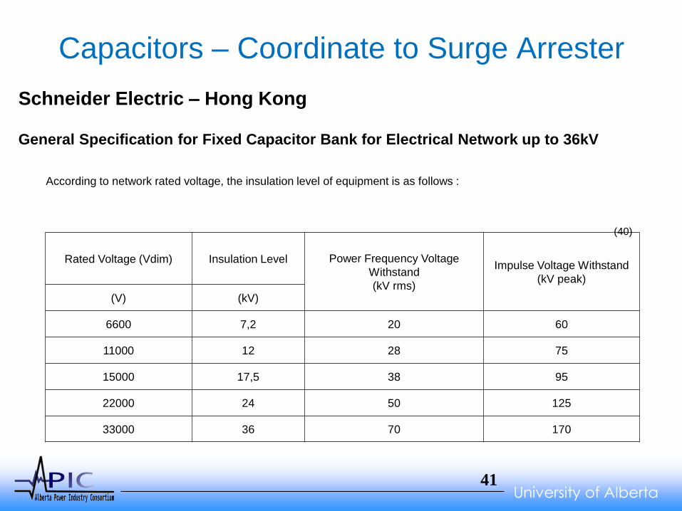
Capacitors – Coordinate to Surge Arrester
According to network rated voltage, the insulation level of equipment is as follows :
Rated Voltage (Vdim) Insulation Level Power Frequency Voltage
Withstand
(kV rms)
Impulse Voltage Withstand
(kV peak)
(V) (kV)
6600 7,2 20 60
11000 12 28 75
15000 17,5 38 95
22000 24 50 125
33000 36 70 170
(40)
Schneider Electric – Hong Kong General Specification for Fixed Capacitor Bank for Electrical Network up to 36kV

University of Alberta 42
Insulators – Coordinate to Surge Arrester
PPC Pin Type Insulators
Catalog Number Frequency 253-S 261-S 263-S 366-S 380-S 386-ST
ANSI Class 55-2 55-3 n/a 55-4 55-5 55-6
Neck Type C C C F F J
Typical Application (kV) 60 Hz 7.2 11.5 11.5 13.2 14.4 23
Dry Flashover Voltage (kV) 60 Hz 45 55 55 65 80 100
Wet Flashover Voltage (kV) 60 Hz 25 30 30 35 45 50
Puncture Voltage (kV) 60 Hz 70 90 90 95 115 135
Impulse Flashover Positive (kV) Impulse 70 90 90 105 130 150
Impulse Flashover Negative (kV) Impulse 85 110 110 130 150 170
Leakage Distance 5" 7" 7" 9" 12" 15"
Dry Arcing Distance 3 3/8" 4 1/2" 4 1/2" 5" 6 1/4" 8"
Cantilever Strength (lbs) 2500 2500 2500 3000 3000 3000
Minimum Pin Height 4" 5" 5" 5" 6" 7 1/2"
Net Weight per 100 (lbs) 183 225 260 390 500 890
Package Weight per 100 (lbs) 191 254 288 400 617 938
Standard Package Quantity 48 24 24 12 12 8

University of Alberta 43
Arrester Class - Parameter #6
• Normal Duty (ND)
• Heavy Duty (HD)
• Riser Pole (RP) (Not a Real Class)
• Intermediate Class
• Station Class
Arrester Class size is Mostly Determined by the
Diameter of the MOV Disk
ND = 1”, HD = 2”, RP = 2”, Inter. = 3”, Station = 4”+

University of Alberta 44
Class Comparisons
Rated
0.5 μsec
10kA500 A
Hubbell
Product
Voltage
kV
MCOV
kVEFOW
Switching
Surge1.5 kA 3 kA 5 kA 10 kA 20 kA 40 kA
1 sec
kV rms
10 sec
kV rms
Normal Duty PDV65-Optima 18 15.3 62.8 46.4 50.1 53.8 57 63.3 72.6 91.2 22.7 21.7
Heavy Duty PDV100-Optima 18 15.3 60.6 43.5 45.4 48.4 51.3 56.4 63.5 75.5 23.5 22.2
Riser Pole PVR-Optima 18 15.3 53.4 35.5 38.9 41.9 44.3 48.9 56.1 66.2 22.2 21.0
Intermediate PVI-LP 18 15.3 51.6 38.3 40.9 43.2 45.2 48.8 54 60.9 21.4 20.5
Station EVP 18 15.3 51.6 36.1 38.5 40.4 42.4 45.5 49.1 56.1 21.7 20.8
8/20 Test Waveform
Maximum Discharge Voltage - kV
Tempoary
Over-Voltage
University of Alberta 45
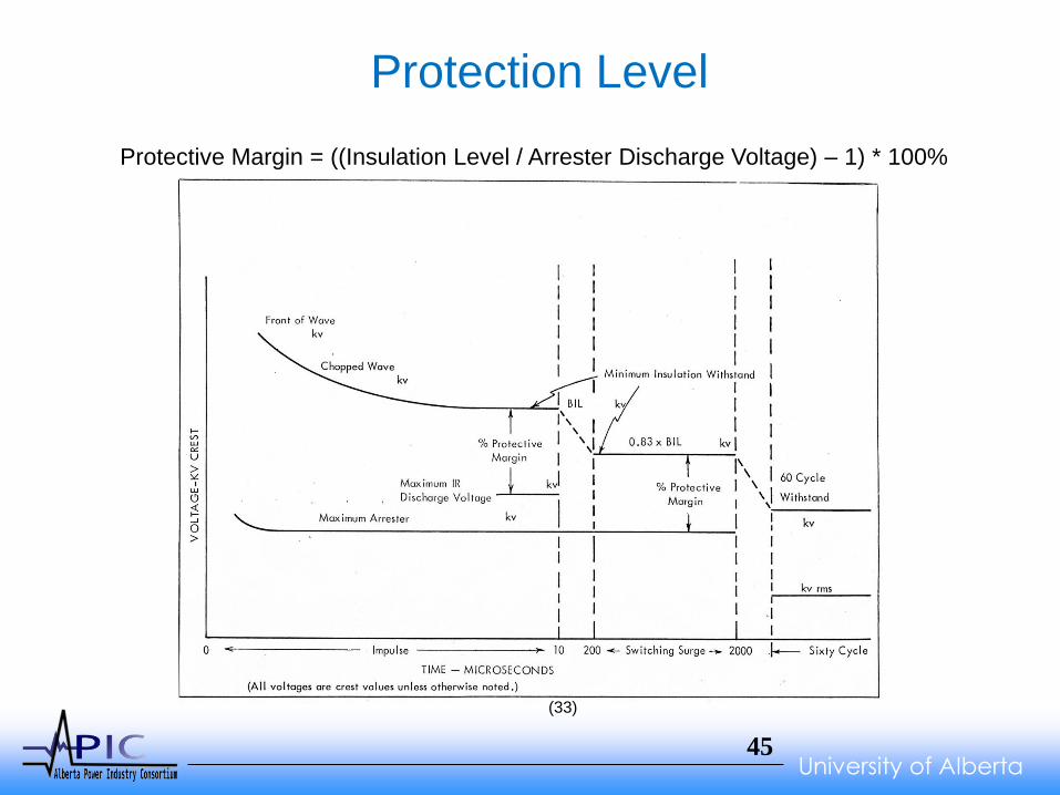
Protection Level
(33)
Protective Margin = ((Insulation Level / Arrester Discharge Voltage) – 1) * 100%

University of Alberta 46
Generic MOV I-V Curve

University of Alberta 47
(42)
University of Alberta 48
Which Arrester Class – What Purpose?
• Your Choice… In Alberta, a low lightning region -
Normal Duty is good enough for general purpose
protection
• Riser Poles – How important is the circuit?
• Capacitors
– Normal Duty is OK,
– Big Banks consider Heavy Duty or Intermediate
• Transformers
– Normal Duty is OK
– Big Expensive Transformers… Heavy Duty or Intermediate

University of Alberta 49
Surge Arresters – How Do They Fail?
• TOV is the Number 1 Killer of Surge Arresters in
Alberta (As reported on Global National, just kidding…)
– The Process is Simple: Overvoltage Physically Heats the
MOV disk, Heat Lowers the MCOV Which Increases the
Heat Generated, Which Lowers the MCOV More, Which
Increases th Heat Generated, until BOOM!
• Today’s Surge Arresters Rarely Fail Due to a Surge
in Alberta. The Quality is Really That Good!

University of Alberta 50
Surge Arresters – Disconnector
(41)

University of Alberta 51
~ Reality Check ~
Should You Be Worried about a Surge Armageddon?
(23)
University of Alberta 52
~ Reality Check ~
No, of course not.
Your own historical data is proof!
But, Asset Life would be Extended Significantly with
the Proper Application of Surge Arresters!

University of Alberta 53
Where to Focus Your Protection
• Transformer Primaries – SHORTEST Lead Length!!!
• Riser Poles – SHORTEST Lead Length!!!
• UG Open Points
• Regulators – Primary & By-Pass
• Reclosers – Line AND Load Sides
• Capacitors
• O/H Dead Ends and N/O Switches

University of Alberta 54
Careful There, Electrical Current!
One Last Thing…
Be Careful Where You Place an Arrester
• Fuses – Surge Current Will Hurt a Fuse
• Capacitors, Regulators, Reclosers, etc
There is NO line or load on these devices,
at least as surge currents are concerned.

University of Alberta 55
Where to Focus your Protection
Just So YOU Know…
Lead Length can ADD up to 1500 Volts/Foot
Lead length is the physical wire distance between the
Apparatus and the Line Side of the Surge Arrester
PLUS (+)
The Line Length from the Ground of the Surge
Arrester to the Ground of Apparatus
AND for the Love of Goodness,
Please Don’t COIL the Leads!!!
University of Alberta 56
A Shameless Promotion arresterworks.com
Deborah Limburg Web and Business Developer
Deborah is a long term veteran in the arrester industry having worked for
Cooper Industries for over 25 years. During that time she held a number of
positions in the product engineering department, including leader of the
Engineering Design Services group. One of her major accomplishments at
Cooper was the design and implementation of a virtual product drawing
systems for all major product lines. This lead to a considerable reduction in
the number of Designers and CAD operators required to maintain the
product documentation system. This database system also helped to
improve the overall documentation process due to the reduction in human
errors.
Additionally she developed the software to handle disk selection process for
the tightly matched disk columns required for series capacitor banks and
the management of the varistor assembly process. Deborah received her
BS in Computer Software from the University of New York State and is a
co-inventor on several US patents.
Since 2010 Deborah has been the Web and Business Developer for
Arresterworks.
Contact at 716-378-1419 or [email protected]
Jonathan Woodworth Principal Engineer
Jonathan started his career at Fermi National Accelerator Laboratory in
Batavia, Illinois, where he was an integral member of the high energy
particle physics team in search of the elusive quark. Returning to his home
state of NY, he joined the design engineering team at McGraw Edison
(later Cooper Power Systems) in Olean. During his tenure at Cooper he
was involved in the design, development and manufacturing of arresters.
He served as Engineering Manager as well as Arrester Marketing Manager
during that time. Since 2008 he has been the Principal Engineer for
ArresterWorks.
Though his entire career, Jonathan has been active in the IEEE and IEC
standard associations. He is past chair of the IEEE SPD Committee, he is
past chair of NEMA 8LA Arrester Committee, and presently co-chair of IEC
TC37 MT4. He is inventor/co-inventor on five US patents. Jonathan
received his Bachelor's degree in Electronic Engineering from The Ohio
Institute of Technology and his MBA from St. Bonaventure University.
Contact at 716-307-2431 or [email protected]

University of Alberta 57
ems, 1990
Over-Voltages and the Distribution System
QUESTIONS?

University of Alberta 58
ems, 1990
References
1 – http://www.picturesof.net/pages/090326-134616-923048.html
2 – www.wordy.photos/index.php?keyword=11%20kv%20fuse%20explodes&photo=0XVPcDxoV2g&category=people&title=electric+power+line+explosion
3 – http://www.satcomlimited.com/transparent_over_voltages.html
4 – http://www.hubbellpowersystems.com/cable-accessories/elbow-arresters/description/
5 – http://www.sandc.com/edocs_pdfs/edoc_024494.pdf
6 – “SURGE ARRESTER APPLICATION OF MV-CAPACITOR BANKS TO MITIGATE PROBLEMS OF SWITCHING RESTRIKES”
Lutz GEBHARDT - ABB – Switzerland, [email protected] & Bernhard RICHTER - ABB – Switzerland, [email protected]
7 – “COMPUTATION OF FAST TRANSIENT VOLTAGE DISTRIBUTION IN TRANSFORMER WINDINGS CAUSED BY VACUUM CIRCUIT
BREAKER SWITCHING”
Casimiro Álvarez-Mariño and Xosé M. López-Fernández, Dept. of Electrical Engineering, Universidade de Vigo, EEI,
Vigo, Spain, [email protected]
8 – http://new.abb.com/products/transformers/distribution
9 – http://commons.wikimedia.org/wiki/File:37.5kVA_three_phase_utility_stepdown.jpg
10 – http://uqu.edu.sa/files2/tiny_mce/plugins/filemanager/files/4310333/traveling_wave.pdf
11 – http://revistas.unal.edu.co/index.php/ingeinv/rt/printerFriendly/25218/33722
12 – http://io9.com/photos-from-the-days-when-thousands-of-cables-crowded-t-1629961917
13 – http://www.edn.com/Home/PrintView?contentItemId=4426566
14 –http://www.ecnmag.com/articles/2011/07/advanced-tvs-construction-improves-lightning-protection
15 – http://www.nautel.com/support/technical-resources/tips-n-tricks/04-09-2012/
16 – http:// www.slideshare.net
17 – https://library.e.abb.com/public/a8c42d637aa10aa2c12577ee0055faad/ABB_DPDQPole_Qpole_revB_EN.pdf
18 – http://www.cooperindustries.com/content/dam/public/powersystems/resources/library/230_PowerCapacitors/23012.pdf
19 – http://www.cooperindustries.com/content/dam/public/powersystems/resources/library/225_VoltageRegulators/MN225008EN.pdf
20 – https://www.osha.gov/SLTC/etools/electric_power/illustrated_glossary/substation_equipment/potheads.html
21 – http://ecmweb.com/archive/applying-pole-mounted-overvoltage-protection
22 – http://www.cpuc.ca.gov/gos/Resmajor/SU6/GO95/SU6_GO95_rule_54_6-F.html
Continued on Next Page
University of Alberta 59
ems, 1990
References - continued
23 – http://creepypasta.wikia.com/wiki/File:5178_apocalyptic_destruction.jpg
24 – http://en.wikipedia.org/wiki/Distribution_transformer
25 – http://www.icccable.com/company_product.html?cid=208
26 – http://www.powertechlabs.com/areas-of-focus/power-labs/cable-technologies/condition-assessment-the-whole-picture/
27 – http://www.ee.washington.edu/research/seal/projects/seal_robot/sensors.html
28 – http://www.epa.gov/electricpower-sf6/documents/sf6_byproducts.pdf
29 – http://cdn2.hubspot.net/hub/272197/file-251812186-pdf/white_papers/afi-wp-transoil1.pdf
30 – http://reliabilityweb.com/index.php/print/defects_in_nonceramic_insulators_can_they_be_detected_in_a_timely_manner1
31 – http://www.inmr.com/thermal-inspection-program-finds-failing-dead-end-polymeric-insulators-2/5/
32 – http://en.wikipedia.org/wiki/Fallout_shelter
33 – http://classicconnectors.com/wp-content/uploads/2012/07/Illustration.jpg
34 – “Electrical Distribution System Protection”, 3rd Edition, Cooper Power Systems, 1990
35 – http://www.cooperindustries.com/content/public/en/power_systems/products/voltage_regulators/32-step_single-phase.html
36 – https://fisitech.wordpress.com/2010/10/22/practical-issues-switching-surgeac-transcient/
37 – http://nepsi.com/services/power-systems-studies/
38 – http://file.scirp.org/Html/3-9800140_1113.htm
39 – http://electrical-engineering-portal.com/definition-basic-insulation-level-bil
40 – http://www.schneider-electric.com/download/hk/en/details/18865768-General-Specification-for-Fixed-Capacitor-Bank-for-Electrical-Network-up-to-
36kV/?reference=Fixed_capacitor_bank_36kV_specENv2
41 – http://www.hubbellpowersystems.com/catalogs/arresters/31_optima.pdf
42 – http://www.coe.montana.edu/ee/seniordesign/archive/SP13/150mwwindfarm/Data_Content/InsulationCoordination.pdf
43 - http://electrons.wikidot.com/semiconducting-ceramics:varistor-applications