Insulating and Air Sealing Low-Pitch Residential Attic ... B12 papers/007-Parsons.pdfRising energy...
15
© 2013 ASHRAE ABSTRACT Rising energy costs and attractive incentive programs established by the government and/or energy companies continue to fuel the need and desire to increase the energy efficiency of residential homes.Air sealing and insulating attic spaces remains one of the best opportunities to attain these energy-efficiency improvements. Low-pitch attics, though, present unique challenges to effectively insulate and air seal them, especially in retrofit situations where the rafter/truss design is fixed and space constraints exist at the perimeter of the structure.The perimeter space constraints limit accessibility to these areas as well as restrict the amount of insulation that can be installed. This paper quantitatively and qualitatively summarizes the cost-effectiveness of various solutions for sealing and insulating attics under low-pitch roofs, with an emphasis on evaluating solutions in areas with space constraints. Insulation and air sealing materials as well as methods for installing those materials were evaluated in a laboratory setting to determine the cost-effectiveness of each method. In addition to the cost versus benefit of each insulating/air sealing solution, the practicality of each approach is compared. INTRODUCTION The Importance of Adequately Insulating and Air Sealing Attics While adequately insulating and air sealing attics conserves energy and reduces energy costs to homeowners, these actions also result in several other positive outcomes. First, air sealing slows air movement through the structure due to stack effects. In the cooler months, stack effects invite air containing moisture from the outside in through leaks at the bottom of the house. The air travels up into the attic. In a venti- lated attic cool roof design, the moisture quickly condenses on cold objects in the attic and/or the underside of the roof and the potential for moisture damage is heightened. Similarly, stack effects may drag radon gases from the ground into a home. Adequately air sealing the attic space can help limit the stack effect, thereby limiting moisture in the attic and slowing radon intrusion into a home. The overall comfort of the home is also improved since drafts are reduced as well. Second, in colder climates, if the attic is not sufficiently insulated or has too much warm air leaking in, the roof deck may become warm enough to melt snow. The water from the melted snow runs downward and freezes on the eaves, creating ice dams. As this phenomenon is repeated, the ice dams grow. The water is unable to flow downward to the eaves and instead moves up under the shingles and roof covering. Ultimately, water leaks into the attic and along the exterior walls. Walls present one of the largest opportunities to improve the air sealing of a building. Between 18% to 50% of a build- ing’s air leakage is through the walls, which includes the leaks into the attic at the top plate (ASHRAE 2005). Insulating and Air Sealing Low-Pitch Residential Attic Spaces: Cost-Effectiveness Evaluation Gary Parsons Mae Drzyzga Member ASHRAE Gary Parsons is a research and development fellow and Mae Drzyzga is a research and development manager with Dow Building Solutions, Midland MI.
Transcript of Insulating and Air Sealing Low-Pitch Residential Attic ... B12 papers/007-Parsons.pdfRising energy...

Insulating and Air SealingLow-Pitch Residential Attic Spaces:Cost-Effectiveness Evaluation
Gary Parsons Mae DrzyzgaMember ASHRAE
ABSTRACT
Rising energy costs and attractive incentive programs established by the government and/or energy companies continue tofuel the need and desire to increase the energy efficiency of residential homes. Air sealing and insulating attic spaces remainsone of the best opportunities to attain these energy-efficiency improvements.
Low-pitch attics, though, present unique challenges to effectively insulate and air seal them, especially in retrofit situationswhere the rafter/truss design is fixed and space constraints exist at the perimeter of the structure. The perimeter space constraintslimit accessibility to these areas as well as restrict the amount of insulation that can be installed.
This paper quantitatively and qualitatively summarizes the cost-effectiveness of various solutions for sealing and insulatingattics under low-pitch roofs, with an emphasis on evaluating solutions in areas with space constraints.
Insulation and air sealing materials as well as methods for installing those materials were evaluated in a laboratory settingto determine the cost-effectiveness of each method. In addition to the cost versus benefit of each insulating/air sealing solution,the practicality of each approach is compared.
INTRODUCTION
The Importance of Adequately Insulating and
Air Sealing Attics
While adequately insulating and air sealing atticsconserves energy and reduces energy costs to homeowners,these actions also result in several other positive outcomes.
First, air sealing slows air movement through the structuredue to stack effects. In the cooler months, stack effects inviteair containing moisture from the outside in through leaks at thebottom of the house. The air travels up into the attic. In a venti-lated attic cool roof design, the moisture quickly condenses oncold objects in the attic and/or the underside of the roof and thepotential for moisture damage is heightened. Similarly, stackeffects may drag radon gases from the ground into a home.Adequately air sealing the attic space can help limit the stack
effect, thereby limiting moisture in the attic and slowing radonintrusion into a home. The overall comfort of the home is alsoimproved since drafts are reduced as well.
Second, in colder climates, if the attic is not sufficientlyinsulated or has too much warm air leaking in, the roof deckmay become warm enough to melt snow. The water from themelted snow runs downward and freezes on the eaves, creatingice dams. As this phenomenon is repeated, the ice dams grow.The water is unable to flow downward to the eaves and insteadmoves up under the shingles and roof covering. Ultimately,water leaks into the attic and along the exterior walls.
Walls present one of the largest opportunities to improvethe air sealing of a building. Between 18% to 50% of a build-ing’s air leakage is through the walls, which includes the leaksinto the attic at the top plate (ASHRAE 2005).
© 2013 ASHRAE
Gary Parsons is a research and development fellow and Mae Drzyzga is a research and development manager with Dow Building Solutions,Midland MI.

Building Code and Government Program
Requirements
The International Codes, ENERGY STAR® QualifiedHomes Program, and United States Department of Energy(DOE) have all acknowledged the importance of insulatingand air sealing attic spaces and have strived to address the issueby mandating minimum requirements and/or providingrecommendations to home owners and builders. The require-ments and recommendations for insulating and air sealingattics have increased over the last decade.
R-Value Minimums for Attic Spaces. The InternationalCodes and the ENERGY STAR Qualified Homes Programoutline minimum R-value targets for insulating attics in newhomes. The DOE has published recommended R-value mini-mums for insulating attics in new and existing homes, indicat-ing a desire and need to address insulation levels in existingresidential structures as well as new structures. Table 1summarizes these minimum R-value requirements.
The International Codes and ENERGY STAR programallow mechanisms other than those identified in Table 1 tosatisfy the attic insulation requirements; Table 1 lists therecommendations for a common compliance mechanismproviding a sense of the R-value expectations for an energy-efficient home. Note the trend towards higher R-value thresh-olds in the International Codes. Also, note that the Interna-tional Codes and ENERGY STAR program requirementsopenly recognize the space constraints along the perimeter ofattics and provide some reduction in the minimum R-valuerequired for this area.
Air Sealing Requirements for Attic Spaces. As withinsulating attic spaces, the International Codes, ENERGY
STAR program, and DOE have placed similar and growingemphasis on air sealing the building envelop of a home.
For example, the 2006 International Residential Code’s(IRC’s) early call for action requiring that “the building ther-mal envelope shall be sealed to limit infiltration” and listingten locations to be “caulked, gasketed, weatherstripped orotherwise sealed with an air barrier material, suitable film orsolid material” (ICC 2006) was quickly and vastly improvedupon. The 2009 and 2012 editions of International EnergyConservation Code (IECC) identify two additional locationsto be sealed and outline compliance verification requirements(ICC 2009, 2012).
The 2009 IECC requires a home to have 7 air changesper hour (ACH) at 50 Pa or be visually inspected by the codeofficial or approved party independent of the installer (ICC2009). The 2012 IECC mandates even tighter homes and morerigorous compliance verification. Under the 2012 IECC,homes must have 5 ACH and 3 ACH at 50 Pa for climatezones 1–2 and climate zones 3–8, respectively. Further, theoption to only visually inspect for air sealing is removed in the2012 IECC, and all homes must be tested (ICC 2012).
The ENERGY STAR program devotes an entire section,Section 5, of its Thermal Enclosure System Rater Checklist toair sealing. Section 5.2.3 specifically requires that the top plateat all unconditioned attics/wall interfaced be sealed to thedrywall. Further, the ENERGY STAR program requires ACHat 50 Pa to be less than or equal to 6, 5, 4, and 3 in climate zones1–2, 3–4, 5–7, and 8, respectively (EPA 2012).
Lastly, the DOE has sponsored and published manyguides and fact sheets to educate and encourage homeownersand home builders to air seal homes (DOE 2000a, 2000b,2000c, 2008, 2010).
Table 1. Minimum Attic R-Value Requirements and Recommendations in IRC (ICC 2006), IECC (ICC 2009, 2012),
ENERGY STAR Qualified Homes Program (EPA 2012), and DOE Fact Sheet (2008)
ClimateZone
2006IRC
2009IECC
2012IECC
ENERGY STAR,Version 3 (Rev. 06)
DOE Insulation Fact Sheet
New HomesUninsulated
Existing Attic3-4 in. of Insulation
in Existing Attic
1 30 30 30 30 30 to 49 30 to 49 25 to 30
2 30 30 38 30 30 to 60 30 to 60 25 to 38
3 30 30 38 30 30 to 60 30 to 60 25 to 38
4 38 38 49 38 38 to 60 38 to 60 38
5 38 38 49 38 38 to 60 49 to 60 38 to 49
6 49 49 49 49 49 to 60 49 to 60 38 to 49
7 49 49 49 49 49 to 60 49 to 60 38 to 49
8 49 49 49 49 49 to 60 49 to 60 38 to 49
NOTE: Under the 2006 IRC, 2009 and 2012 IECC, and ENERGY STAR Qualified Homes Program, R-30 is deemed to satisfy requirements for R-38 whenever the full height ofuncompressed R-30 insulation extends over the wall top plate at eaves. Similarly, R-38 is deemed to satisfy requirements for R-49 whenever the full height of uncompressed R-38insulation extends over the wall top plate at eaves.
2 Thermal Performance of the Exterior Envelopes of Whole Buildings XII International Conference

Low-Slope Attics: Where Space Constraints Limit
Insulating and Air Sealing
While strong driving forces exist to adequately insulateand air seal attics, low-slope attics pose space constraints andmake insulating and air sealing a challenge. While many roofdesigns exist, most designs closely resemble either a hip or agable roof system. In a gable roof system, assuming a rectan-gular footprint, the perimeter space constraints presented bythe truss/rafter design are largely present on only two sides ofthe home. By contrast, in a low-slope hip roof system, the attichas truss/rafter design constraints on all four sides and thecorners.
Sources conflict on the exact definition of a low-sloperoof, with some defining a rise of 3 units or less for every 12units of horizontal distance (i.e., 3/12 slope) as a low slope andothers citing a 2/12 slope (ASTM 2006; Feirer and Feirer2004; CoolFlatRoof.com 2012). Regardless of the exact defi-nition, roofs with even as much as a 5/12 slope are still signif-icantly space constrained and pose accessibility challenges forinstalling insulation and air sealing.
Figure 1 illustrates the space constraints. It provides avisual of how the space for installing insulation and physi-cally maneuvering to do installation work in an attic shrinksas the roof slope decreases from 8/12 to 3/12. It also shows
the approximate distance from the exterior of the top plate tothe interior of the attic required before enough vertical spaceexists to insulate to an R-30 and R-49 level using a genericR-3.5/inch insulation.
The 2006 IRC, 2009 IECC, 2012 IECC, and ENERGYSTAR program all extend some latitude in their insulationrequirements for space-constrained areas around the perime-ter of the attic (see the note in Table 1). But, even a denselypacked insulation can require 8 in. of vertical space beforereaching an R-30 level, which is not available along the perim-eter of many low-slope attics.
In new construction, several approaches can be used tobuild a home with a low-slope roof and provide sufficientspace to physically access for air sealing and adequately insu-lating the attic perimeter. Three popular approaches includeraised heel truss systems, extended bottom chords, anddropped chord trusses (see Figure 2).
Of the three approaches, the raised heel truss system hasbeen the most popular in recent years. It creates a slightlyhigher wall as viewed from the exterior of the structure. Bycontrast, the extended bottom chord approach maintains thetraditional wall height appearance; however, it does result ineaves that project further beyond the home’s walls than“normal.” Finally, the dropped chord truss, like the raised heel
Figure 1 Attic space constraints increasing with decreasing roof slope, negatively impacting the attic insulation levels.
Figure 2 New construction methods for increasing vertical space along the perimeter of a low slope attic: raised heel truss,extended bottom chord, and dropped bottom chord.
Thermal Performance of the Exterior Envelopes of Whole Buildings XII International Conference 3

truss, results in a slightly taller wall appearance from the exte-rior of the home.
In new construction, low-slope roofs and their sealing andinsulating challenges can be avoided through the design ofsteeper roof slopes. Similarly, a hip roof system with its space-constrained corners is an option that can be ruled out in thedesign phase of new construction. Unlike new construction,though, retrofitting an existing home with a low-slope roof toensure adequate insulation and air sealing is a challenge thatcannot be designed out.
Accordingly, the challenge of air sealing and insulatingexisting low-slope roofs is the subject of the researchpresented here. The objectives of this research were to
• understand current methods employed to address thischallenge,
• conduct a series of simulated installations to evaluatethe methods known today, and
• begin a data-based discussion on the most effectivemethods to address space-constrained attic areas.
The authors acknowledge that a potential option toaddress air sealing and insulating an existing, unconditioned,vented low-slope attic is to convert the attic into a nonvented,conditioned space. While this is a viable option that should beconsidered in a broad discussion on air sealing and insulatinghomes, for this research nonvented roofs were left out of thescope.
Current Air Sealing and Insulating Methods
Recommended/Employed for Constrained
Attic Spaces
Literature Review and Internet Search.While the chal-lenge is broadly recognized, a literature review and internetsearch found limited information on recommendationsspecific to addressing the challenges of air sealing and insu-lating existing low-slope attics. The review did reveal genericattic air sealing and insulation instructions specific to the topplate area, which are relevant to the research topic since, asdiscussed previously, the attic perimeter typically representsthe most space-constrained area of the attic.
After first instructing to pull back any existing insulationin the attic and install baffles along the roof rafters when miss-ing, the instructions offered three options, discussed in detailin the following subsections. Only one source offered thesecond option listed, which, interestingly, offers some poten-tial to increase the R-value around the perimeter of the atticusing foam boards, which typically have a higher R/in. thantraditional blown-in or loose-fill attic insulation materials(e.g., R-5 to 6.5 verses approximately R-3.5 to 3.8).
OPTION 1: Air Seal without Improving Insulation(DOE 2010; Lstiburek 2012)
i. Apply a continuous bead of either one-component foamor caulk sealant to the gaps between the drywall, orientedstrand board (OSB), and top plate, with most referencesonly calling for the sealing of the gap between the drywalland top plate.
ii. Place a fiberglass roll at the top plate to provide additionalsupport to the baffle.
OPTION 2:Air Seal and Improve Insulation (North 2012)
i. Apply a continuous bead of either one-component foamor caulk sealant to the gaps between the drywall and topplate.
ii. Fit a foam sheet/block extending from over the exteriorsheathing to at least the interior drywall.
iii. Install a second foam sheet/block vertically, flush againstthe outside edge of the attic baffle. Seal around the atticbaffle and the vertical foam block seams.
OPTION 3:Abandon Ventilation in Some Areas to Improve Air Seal(DOE 2010; Lstiburek 2012; Straube 2012)
i. Place fiberglass in large opening between roof deck,rafters, ceiling joists, and top plate, where baffles cannotbe installed.
ii. Apply two-component air sealing spray foam to the topplate area.
All three options concluded with instructions to reinstallpreviously existing insulation and/or add new loose-fill orblown-in insulation.
Phone Interviews with and Completed Questionnairesfrom Experienced Home Performance Retrofitters. Expe-rienced home performance retrofitters’ phone interviews andcompleted questionnaires revealed several consistent themes:
• Experience matters; solutions often need to be custom-ized to the situation
• One- and two-component spray polyurethane foams arepopular, often with customized dispensing guns
• Air sealing is a priority over insulation
Other methods employed by home performance retrofit-ters to address the top plate and corners of attics included:
i. Reconstructing the roofii. Conducting air sealing via the exterior eave area as an
access pointiii. Removing/replacing interior drywalliv. Sealing/insulating the wall cavities with urea formalde-
hyde urethane foam or dense pack cellulosev. Doing nothing.
4 Thermal Performance of the Exterior Envelopes of Whole Buildings XII International Conference
Some retrofitters indicated that in many homes the costand effort to air seal and insulate attics, especially those withaccess challenges or located in southern climates, did notreturn cost savings as high as those from making improve-ments to other areas of the home.
Like the option to convert an unconditioned, vented atticinto a conditioned, nonvented attic, the methods identified inthis numbered list to air seal and insulate the attic are viableapproaches that should be considered in a broad discussion onair sealing and insulating a home. However, to adequatelyconsider all of these approaches is too large a task with theresources available and under the scope of one research proj-ect.
Accordingly, the scope of this research project waslimited to employable techniques for air sealing and insulatingconstrained, vented attic spaces that require no renovations(e.g., replacing the roof deck) and are accomplished from theinterior of the attic.
EXPERIMENTAL DESIGN
Test Equipment
The laboratory work conducted for this researchemployed a duct blaster with a digital pressure and flow gaugeand two mock attic structures designed to conduct qualitativeand quantitative research.
The duct blaster had three flow-ring configurations avail-able, each corresponding to a different airflow range and mini-mum fan pressure. Based on the differential pressures targetedand the airflows generated during this research, a ring with aflow range of 10–125 cfm and a minimum fan pressure of 3 Pawas employed for all duct blaster testing (EC 2012).
The digital pressure and flow gauge used in conjunctionwith the duct blaster is capable of pressure measurements thatare accurate to ±1% of the reading from –1250 to 1250 Pa. The
duct blaster, when used with this specific digital pressure andflow gauge, has a flow accuracy of ±3% (EC 2011).
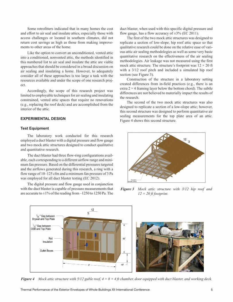
The first of the two mock attic structures was designed toreplicate a section of low-slope, hip roof attic space so thatqualitative research could be done on the relative ease of vari-ous attic air sealing methodologies as well as some very basicquantitative research on the effectiveness of the air sealingmethodologies. Air leakage was not measured using the firstmock attic structure. The structure’s footprint was 12 × 20 ftwith a 3/12 roof pitch and included a simulated hip roofsection (see Figure 3).
Construction of the structure in a laboratory settingcreated differences from in-field practices (e.g., there is anextra 2 × 4 framing layer below the bottom chord). The subtledifferences are not believed to materially impact the results ofthe research.
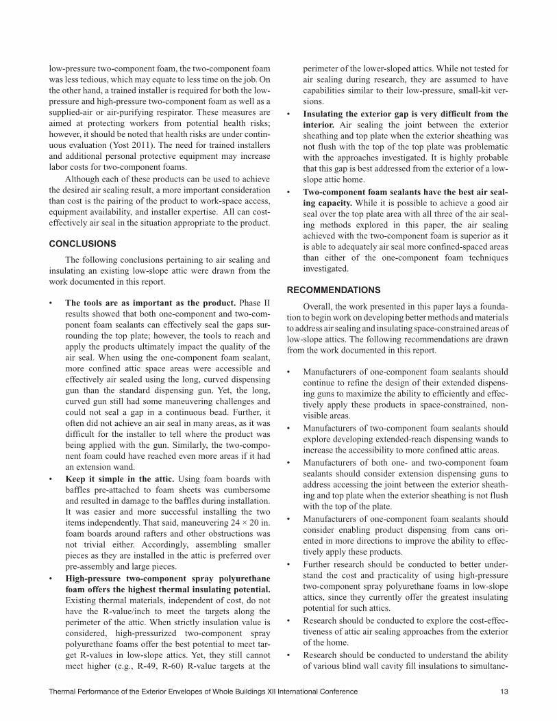
The second of the two mock attic structures was alsodesigned to replicate a section of a low-slope attic; however,this second structure was designed to perform quantitative airsealing measurements for the top plate area of an attic.Figure 4 shows this second structure.
Figure 3 Mock attic structure with 3/12 hip roof and12 × 20 ft footprint.
Figure 4 Mock attic structure with 5/12 gable roof, 4 × 8 × 4 ft chamber, door equipped with duct blaster, and working deck.
Thermal Performance of the Exterior Envelopes of Whole Buildings XII International Conference 5

The deck on the right-hand side of the structure wasstrictly to simulate accessing the attic top plate as an installerwould do in the field (i.e., it enabled the installer to stay lowon his belly to do the installation work).Air infiltration studieswere done on the hut-like structure to the left of the installerdeck. The hut consisted of a small chamber below an attic. Thesmall chamber provided an area to allow suction by the ductblaster.
The chamber had a 4 × 8 ft footprint. It was built on a 2 × 4framed floor, with one single 4 × 8 ft sheet of OSB making upthe solid floor surface.
The walls were 4 ft in height and framed 16 in. on centerwith 2 × 4 studs. Kraft-faced R-13 fiberglass batts wereinstalled in the wall cavities with the kraft facer closest to theinterior of the wall. Three rectangular electrical outlets wereinstalled in one interior wall.All four walls were sheathed withsolid sheets of drywall on the interior and solid sheets of OSBon the exterior. Similar to common construction practices, theexterior OSB sheathing was not flush with the top face of thetop plate; rather, the top of the OSB sat approximately 1/2 in.below the top face of the top plate. Washers were placedbetween the sheathing and the top and bottom plates to intro-duce a ~1/32 in. air gap to simulate air gaps found in fieldconstruction that occur as a result of lumber drying (Onyskoand Jones 1989). All drywall seams were taped and mudded.
These features were all included to simulate actual construc-tion.
The roof was approximately a 5/12 slope and comprisedof ceiling joists and roof rafters spaced 24 in. o.c. The twoshort sides were sheathed with OSB to the top of the roof deckand constructed to simulate gable ends. One long side had therafters protruding over the wall edge to create an eave area.The other long side was left open to access the attic from thedeck.
The mini-door with the port for attaching the duct blasterwas installed using a standard door frame. The floor sill wassealed with silicone and the other edges were sealed with one-component foam. All penetrations used for tubing inserts aspart of the pressure measurements were sealed with silicone.
Air Sealing and Thermal Insulating Techniques Eval-uated. Based on the results of the literature search and homeperformance retrofit contractor information gathered, threestrategies were selected to evaluate:
i. Air sealing without improving insulationii. Air sealing and improving insulationiii. Air sealing and improving insulation at the expense of
ventilating portions of the attic
A matching, abbreviated description of the techniquefound in the literature to undertake each strategy is describedin Figure 5 and identified as either1, 2, or 3.
Figure 5 Experimental strategy for investigating air-sealing and thermal-insulating techniques.
6 Thermal Performance of the Exterior Envelopes of Whole Buildings XII International Conference

As shown in Figure 5, as the research progressed beyondthe literature search into the qualitative and quantitativephases, each technique originally found in the literature wasrefined. New information was learned in each phase, helpingto optimize techniques. Optimized techniques are identifiedwith their original technique number followed by a chrono-logical alpha-character, representing the order the techniquewas integrated into the research project.
Note that for the first two strategies the literature wasfairly broad in recommending a “sealant.” To keep the scopeof this research manageable, a one-component polyurethanefoam sealant was selected to conduct the qualitative and quan-titative research under techniques 1 and 2.
Figure 6 shows the difference between the standard lengthand long, curved dispensing gun used with the one component(1 K) polyurethane foam during phase I.
As explained previously, the foam board used in tech-niques 2a, 2b and 2c can enhance the R-value along the atticperimeter over more traditional attic insulation materials. Inaddition, it was hypothesized that the foam board could bepressed down upon by the installer to help compress anddistribute the one-component foam, thereby further aiding inair sealing. A 1 in. thick foil-faced polyisocyanurate foam wasused in all testing.
The dispensing system for the two-component foam seal-ant used in phases I and II consisted of a set of hoses, a mixingnozzle, and a cone tip.
TEST PROCEDURES
As mentioned previously, this research involved theconstruction of two mock attic structures, which were eachused to conduct two separate phases of experiments.
Phase I Test Procedures
Phase I utilized the 12 × 20 ft mock attic structure, whichhad a tarp installed on the open 12 ft end to help simulate thedark, limited visibility conditions of an attic. The long 20 ftend was left open, as a flood light would most likely be placedin the center of an attic during real-life retrofit work. Theresearch installer’s access was constrained to simulate anactual attic access situation.Again, this ground rule was estab-lished to help simulate real-life retrofit work. Most of the datacollected in phase I was qualitative.
The first task in phase I involved having the installer enterthe attic area and mark the point of his furthest physical reachalong the perimeter of the entire attic structure. The roof deckwas then removed and the distance between the top plate andceiling drywall joint and the point of reach was measured.Photos were taken to visually document the reach points.
Next, the techniques outlined in Figure 5 for phase I wereexecuted. Note that the same experienced installer was usedfor all installation tasks in this research program. In addition,all necessary materials for each technique were pre-staged inthe attic structure.
Techniques 1a and 1b required the installer to apply one-component foam to the top plate. Two beads were applied. Onewas targeted between the exterior sheathing and top plate. Thesecond bead was targeted between the top plate and interiordrywall. The installer used the standard dispensing gun in twocavities and the long, curved gun in six cavities.
For techniques 2a and 2b, the foam sheet was pre-cut to~24 in. wide by 16–20 in. long. Foam baffles were pre-attached to the foam sheet by pushing four or five drywallscrews through the foam baffle and foam insulation board (seeFigure 7). The hypothesis was that having the baffle pre-attached to the foam would ease baffle installation by acting asan extension arm to get the baffle into place. Foam sheets werelimited to the 16–20 in. length based on the assumption thatgreater lengths would be difficult to maneuver in a confinedattic space.
For technique 2a, where the one-component foam wasapplied to the top plate using the long, curved dispensing gun,four cavities were employed. For technique 2b, three cavitieswere employed and the standard dispensing gun was used toapply the sealant to the foam sheet (see Figure 8).
For technique 3a, foam baffles were installed in all rafterspaces that the installer was able to access. The installerattempted to stuff ~36 in. long by 3.5 in. thick fiberglass intothe ends of the cavities where he was not able to install a baffle.A broom stick was used to ball up the fiberglass and push it outover the soffit area. Once the baffles and fiberglass were inplace, the installer left the attic space, suited up in a protectivesuit and full respirator, re-entered the attic space, and installedthe two-component polyurethane foam sealant.
For each installation step and technique, installer feed-back was immediately captured after the work was completed.Foam was given adequate time to cure, and then the roof deck
Figure 6 Standard-length dispensing gun compared tolong, curved dispensing gun.
Thermal Performance of the Exterior Envelopes of Whole Buildings XII International Conference 7

was removed. A qualitative analysis of air sealing effective-ness and photographic documentation was then conducted.
Phase II Test Procedures
Phase II employed the 4 × 8 ft by 4 ft tall chamber withthe ~5/12 slope roof and duct blaster to quantitatively measureair infiltration improvements after three different air sealingtechniques were applied to gaps on either side of the top plate(refer to Figure 5). The installer had the same ground rules asin phase I, with no body part allowed above the highest pointof the attic structure and all materials required to be pre-stagedeither in the attic or on the work deck.
For technique 1b, two beads of one-component foamwere applied using the long, curved dispensing gun. The firstbead targeted the gap between the interior ceiling drywall andthe top plate. The second bead targeted the gap between the topplate and exterior OSB sheathing
For technique 2c, the first bead of the one-componentfoam was applied onto the interior ceiling drywall, slightlyforward of the gap between the drywall and top plate. Phase Ihad shown that as the foam sheet was pushed out over the topplate area it also pushed the foam sealant. Accordingly, byplacing the bead slightly forward of the gap intended to be airsealed, it was hypothesized that bead would move to the ulti-mately intended location. A second bead was still appliedalong the gap between the interior ceiling drywall and topplate, though. The third bead applied targeted the outer edgeof the top plate. This area was identified as the target after tech-nique 1b was employed during phase II. During that step, itwas not possible to maneuver the dispensing gun to apply thefoam sealant directly to the gap between the top plate and theOSB sheathing with the sheathing sitting 1/2 in. below the topface of the top plate. Thus, the hypothesis was that it might bepossible for a bead of foam to be applied to the outer edge ofthe top plate to “fall into place” as the foam sheet was installed,sealing this outer gap.
No air sealing difference had been seen in phase I betweenusing baffles or fiberglass batts as a backer material for thetwo-component foam. Foam attic baffles were selected forphase II, technique 3a, since they would typically be used inmost attic cavities.
The measurement procedure for phase II first involvedtaking an air infiltration measurement with both the interiorand exterior sheathing to top plate gaps sealed with construc-tion tape to establish what a very good air infiltration ratewould be for the chamber if both gaps around the top platewere sealed. This measurement was noted as the targetedperformance level. Note that all other gapped areas were alsosealed with construction tape to establish the targeted perfor-mance level as well as to determine the performance level ofeach of the three techniques tested (i.e., researchers taped gaps
Figure 7 Foam attic baffle pre-attached to 1 in. polyisocyanurate foam insulation board using drywall screws.
Figure 8 Application of 8–10 in. of one-component foamsealant to polyisocyanurate foam board with atticbaffle pre-attached.
8 Thermal Performance of the Exterior Envelopes of Whole Buildings XII International Conference

around the bottom plate, gaps between the OSB sheathing,gaps between rafter ends and OSB sheathing, etc.).
Once the targeted performance level measurements werecomplete, a baseline measurement with no tape on either sideof the top plate was conducted. This was important to dobefore each new air sealing method was installed since thesame structure was to be used for each air sealing method.While the previous air sealing material would be removedprior to installing the next method, no guarantee could bemade that all the air sealing material would be removed or thatthe gap size might not be increased in some areas as the oldmaterial was chipped away.
Each technique outlined in Figure 5, as well as thetargeted performance level, was tested at 25 and 50 Pa pressuredifferentials. At each pressure differential, five airflowmeasurements were collected at 20 s apart. The average of thefive measurements was rounded to the nearest whole numberand reported.
RESULTS
Phase I Results
Phase I results are summarized in Figure 9 and Table 2.Figure 9 illustrates how far the installer was able to physicallyreach into various areas of the low-slope roof assembly. Itprovides a visual guide to understanding the constraints aninstaller faces when air sealing such structures. Table 2captures both the air sealing observations and the installer
feedback for each phase I air sealing and thermal insulatingtechnique. Figures 10–12 provide visual examples of the airseal achieved for the techniques employed in phase I.
Figure 10 exemplifies what a good-quality sealant instal-lation around the top plate looked like using technique 1a or 1brelative to poor installation quality around the top plate. Simi-larly, Figure 11 shows what a quality sealant installationlooked like using technique 2a and a poor-quality installationusing technique 2b. In the case of technique 3a, if an installerwas able to reach into a given cavity to apply the two-compo-
Figure 9 Bird’s-eye view of attic mock up: distancebetween the furthest physical reach point to theinterior top plate edge.
Table 2. Phase ITesting Summary,Techniques 1a, 1b, 2a, 2b, and 3a
Phase ITechnique
Sealant Installation Quality Results Summary Key Learnings
1a • Sealant installation quality was poor. • Extended-length, curved dispensing gun works better than stan-dard-length dispensing gun.
• Design improvement opportunities exist for the extended gun toenable more flexible positioning of the gun in a confined area.
• Installation could be optimized if the one-component foam canproduct could be interchangeably positioned vertically and hori-zontally.
1b• Reach was to cavity I.• Sealant installation quality was good to cavity D.
2a • Sealant installation quality was good. • Pre-attached foam baffles to a foam sheet are cumbersome tomaneuver, become easily damaged, and limit the reach of thetechnique.2b • Sealant installation quality was poor.
3a
• Reach was to cavity E installing foam baffle.• Reach was to cavity I installing rolled fiberglass batt.• Reach was to cavity G installing two-component foam.• Sealant installation quality was good in all cavities
reached, installing the two-component foam (e.g., tocavity G).
• An extension wand at the end of the dispensing hose wouldenable accessing more areas.
Overall
• Easiest installation, physically: One-component with the extended, curved dispensing gun.• Longest reach: One-component with the extended, curved dispensing gun.• Best sealant installation quality: i) Pre-attached baffle to foam sheet with one-component applied to top plate
OR ii) two-component spray foam.• Best sealant installation quality/reach balance: Two-component spray foam.
Thermal Performance of the Exterior Envelopes of Whole Buildings XII International Conference 9

nent foam, the top plate area appeared completely air sealedduring post-installation inspection (see Figure 12).
Phase II Results
Phase II results are summarized in Figure 13. Recall thatonly the good-quality installation approaches from phase Iwere tested in phase II. The reduction in air infiltration wasgenerally the same for all three air sealing techniquesemployed at pressure differentials of 25 and 50 Pa.
All three techniques had a large performance gap relativeto the targeted performance level, having air leakage rates 20%to 35% greater than the target. Recall that both the interior andexterior top plate gaps were sealed with construction tape andair infiltration was measured at the outset of phase II, repre-senting the target performance level for each techniqueemployed.A large portion of the delta from the target can mostlikely be attributed to the inability of techniques 1b, 2c, and 3ato reach and seal the gap between the exterior sheathing andthe top plate.
Figure 10 Examples of good- and poor-quality foam sealant installations using techniques 1b and 1a, respectively.
Figure 11 Examples of good- and poor-quality foam sealant installations using techniques 2a and 2b, respectively.
Figure 12 Example of a good-quality foam sealantinstallation using technique 3a.
10 Thermal Performance of the Exterior Envelopes of Whole Buildings XII International Conference

DISCUSSION
Practicality and Effectiveness of
Air Sealing Methods Explored in Phase II
Generally, the installer could not physically reach closerthan within about 14 in. of the interior edge of the top plate;however, it was possible to apply air sealing materials to mostof the perimeter of a 3/12 slope roof using various reach exten-sion tools and techniques. With the 3/12 hip roof, the installerwas generally able to apply air sealing materials within 6 ft ofthe corner.
Various techniques were explored during the early phasesof this research program; however, they were eventuallyrefined and narrowed to three techniques that were quantita-tively tested in phase II, yielding similar performance results.Since these three techniques were deemed most suitable foruse in low-slope attics relative to the other techniquesexplored, only phase II air sealing techniques are discussed atgreater length in this paper.
With three significantly different techniques for air seal-ing the top plate yielding similar quantitative air infiltrationreductions in a laboratory setting during phase II, it is easy tounderstand why home performance retrofitters consistentlystated that a “one size fits all” approach does not exist. Eachinstallation technique employed in phase II was equal in termsof air infiltration reduction; however, the practicality andfeasibility study in phase I revealed pluses and minuses of thetechniques that would need to be considered for an in-fieldattic retrofit.
First, while the one-component foam applied using thelong, curved dispensing gun was physically the easiest tech-nique to execute and gave the installer the longest reach, thequality of the air seal was not as good at extended distances asit was using other techniques. The dispensing gun wasdesigned for pinpointed application of the foam sealant. Theinstaller, though, could not see if he was applying the foam
along the gaps. The installer had to rely on intuition or, in thecase of a larger, well-defined gap, feeling the dispensing gunsetting into the gap and then moving along the gap.
Further, the one-component foam sealant technique wasalso plagued by limited maneuverability of the can and long,curved dispensing gun. The can must be in the vertical positionto apply the product. The long, curved dispensing gun couldnot be adequately rotated in the confined space to enableapplying one long, continuous bead of foam sealant in a givencavity. Rather, the installer had to stop short of the full cavitywidth, reposition the dispensing gun, and finish applying thefoam sealant the remainder of the cavity width.
The second technique of applying one-component foamto the top plate area and then installing a pre-sized foam sheetextending over the top plate area and slightly into the mainattic floor space also faced maneuverability issues. The foamsheet was cumbersome to maneuver around rafters and objectspenetrating through the attic. While not completely resolved,some of these issues were reduced when the pre-attachedbaffle used in phase I was removed in phase II. Logistics aside,one significant disadvantage of this method was the need topre-cut the foam sheets to size. For in-field applications,depending on the attic layout, this could be tedious.
Despite its in-field limitations, this technique was stillconsidered after phase I largely since it presented a viablemethod to improve the thermal insulation levels around theperimeter of an attic. Assuming a 3 in. thick R-6.5 foam insu-lation and a generic R-3.5 insulation installed over the foam,Figure 14 illustrates the shrinking distance of the underinsu-lated area for R-30 and R-49 targets using this technique witha 3/12 roof. Overall, for a 32 × 40 ft attic, the technique enables~10% more of the attic area to be insulated to the target value.
The third and final technique explored, using a two-component foam to seal the top plate area, seemed to offer thebest balance between reach and air seal quality. While thereach was not as far as the long, curved dispensing gun usedwith the one-component foam, the two-component foam tech-nique was able to effectively air seal cavities further out thanthe one-component technique. The reach of the two-compo-nent foam might be improved if an extension wand was avail-able to attach to the end of the dispensing hose. Thedisadvantage of using a two-component polyurethane foamsealant in field is that it requires a specially trained installerwho must wear a respirator during the installation.
For all three techniques, the dispensing equipment in-field cleaning factor was a disadvantage. The one-componentgun had to be cleaned after application to approximately everyfifth cavity, otherwise the nozzle would have a large glob offoam build-up on its end. The tip on the two-component foamdispensing equipment had to be replaced every time theinstaller had to reposition and relocate himself on the OSBboards laid over the ceiling joists. Otherwise, the foam wouldharden in the tip and block dispensing. This worked out to beapproximately every third cavity. Overall, in-field cleaning
Figure 13 Reduction in air infiltration in cubic feet perminute (cfm) obtained by sealing the top plateusing techniques 1b, 2c, and 3a.
Thermal Performance of the Exterior Envelopes of Whole Buildings XII International Conference 11

requirements were cumbersome to execute in the confinedattic space and slowed the installation work.
Unfortunately, all three air sealing techniques shared aquantitative performance gap. None were able to address seal-ing between the top plate and exterior sheathing when the exte-rior sheathing was not flush with the top plate. While fewsources specifically recommended sealing this gap and severalhome performance contractors voiced consciously not work-ing to seal this gap, this gap does offer significant potential forair leakage in a home. Assuming a 1/32 in. gap on each side ofthe top plate, an unsealed gap between the top plate and theexterior sheathing represents slightly more than 50% of the107 in.2 of open space around the top plate in a 32 × 40 ft atticspace.
Air Sealing and Insulating Limitations
for 3/12 Slope Hip Roof
Most home performance retrofit contractors commentedthat they deem air sealing to be more important than insulat-ing. Some of their emphasis on air sealing may be due to theinability to insulate low-slope attics due to a lack of materialswith R-values high enough to insulate height-constrainedattic spaces of attics to the targeted values. Blown-in cellulose(R-3.8/in.) generally offers a higher R-value than blown-infiberglass (typically ~R-3/in.) and is most commonly used(CIMA 2012; CertainTeed 2011; GBP 2008a, 2008b; Green-fiber 2012; JM 2012; Owens Corning 2012). If a 3/12 sloperoof attic has a targeted R-49 insulation level, though, blown-in cellulose can only insulate approximately 66% of a 32 ×40 ft attic area to this target level.
Foam insulation board products can offer a higher R/in.(e.g., up to R-6.5/in.). However, they are cumbersome to installin an attic and their impact on achieving targeted R-values inattics is minimal unless relatively thick boards are used. For a32 × 40 ft home with a 3/12 roof, adding a 1 in. thick R-6.5 foamsheet under blown-in cellulose only enables ~68% of the atticarea to be insulated to a R-49 target. Adding a 3 in. thick R-6.5
foam sheet under blown-in cellulose enables ~73% of the atticarea to be insulated to an R-49 target.
Two-component spray polyurethane high pressurizeddrum foams can offer R-values comparable to foam boards(e.g., R-6.5). In a 32 × 40 ft attic with a 3/12 slope, it can beinstalled at heights that would result in the R-49 target beingrealized in ~86% of the attic area.
Cost Considerations
Recognizing every attic space is different and costs fluc-tuate (i.e., over time, by geographic regions, between manu-facturers, etc.), some basic considerations of cost areappropriate.
First, a 24 oz can of one-component polyurethane foamsealant can typically be purchased for less than $20 per can. Bycontrast, a ~100 board foot two-component spray foam sealantcosts between $200 to 300, and a 55 gal drum set of high-pres-sure drum foam runs around $2000 (Diamond Tool 2012;FarmTeck 2012a, 2012b; Home Depot 2012; Industrial Prod-ucts 2012a, 2012b; Lowe’s 2012; Menards 2012a; SD 2012;SoyThane 2013). Accordingly, the initial sticker price of boththe two-component foams can be an immediate deterrent to anindividual inexperienced with the relative effectiveness ofattic air sealing and insulating of various materials. Of course,the 24 oz can will not cover as much area as the 100 board footkit or 55 gal drum set, but its functionality is limited to air seal-ing whereas many two-component foams offer insulation.
On a board foot (BDF) basis, the material cost of the two-component low-pressure foam can be five times the cost of thetwo-component high-pressure drum foam. At the low end ofthe material cost for two-component low-pressure foam, thecost is typically 40% higher than the cost of the two-compo-nent high-pressure drum foam on a BDF basis.
Next, moving beyond the sticker shock, the labor costs foreach technique might vary. It has been reported that labor costsoften outweigh material cost considerations (Keefe 1995).While this research indicated that it was physically easier toinstall the one-component foam in the laboratory attic than the
Figure 14 Shrinking distance of underinsulated area using technique 2c in a 3/12 roof.
12 Thermal Performance of the Exterior Envelopes of Whole Buildings XII International Conference
low-pressure two-component foam, the two-component foamwas less tedious, which may equate to less time on the job. Onthe other hand, a trained installer is required for both the low-pressure and high-pressure two-component foam as well as asupplied-air or air-purifying respirator. These measures areaimed at protecting workers from potential health risks;however, it should be noted that health risks are under contin-uous evaluation (Yost 2011). The need for trained installersand additional personal protective equipment may increaselabor costs for two-component foams.
Although each of these products can be used to achievethe desired air sealing result, a more important considerationthan cost is the pairing of the product to work-space access,equipment availability, and installer expertise. All can cost-effectively air seal in the situation appropriate to the product.
CONCLUSIONS
The following conclusions pertaining to air sealing andinsulating an existing low-slope attic were drawn from thework documented in this report.
• The tools are as important as the product. Phase IIresults showed that both one-component and two-com-ponent foam sealants can effectively seal the gaps sur-rounding the top plate; however, the tools to reach andapply the products ultimately impact the quality of theair seal. When using the one-component foam sealant,more confined attic space areas were accessible andeffectively air sealed using the long, curved dispensinggun than the standard dispensing gun. Yet, the long,curved gun still had some maneuvering challenges andcould not seal a gap in a continuous bead. Further, itoften did not achieve an air seal in many areas, as it wasdifficult for the installer to tell where the product wasbeing applied with the gun. Similarly, the two-compo-nent foam could have reached even more areas if it hadan extension wand.
• Keep it simple in the attic. Using foam boards withbaffles pre-attached to foam sheets was cumbersomeand resulted in damage to the baffles during installation.It was easier and more successful installing the twoitems independently. That said, maneuvering 24 × 20 in.foam boards around rafters and other obstructions wasnot trivial either. Accordingly, assembling smallerpieces as they are installed in the attic is preferred overpre-assembly and large pieces.
• High-pressure two-component spray polyurethanefoam offers the highest thermal insulating potential.Existing thermal materials, independent of cost, do nothave the R-value/inch to meet the targets along theperimeter of the attic. When strictly insulation value isconsidered, high-pressurized two-component spraypolyurethane foams offer the best potential to meet tar-get R-values in low-slope attics. Yet, they still cannotmeet higher (e.g., R-49, R-60) R-value targets at the
perimeter of the lower-sloped attics. While not tested forair sealing during research, they are assumed to havecapabilities similar to their low-pressure, small-kit ver-sions.
• Insulating the exterior gap is very difficult from theinterior. Air sealing the joint between the exteriorsheathing and top plate when the exterior sheathing wasnot flush with the top of the top plate was problematicwith the approaches investigated. It is highly probablethat this gap is best addressed from the exterior of a low-slope attic home.
• Two-component foam sealants have the best air seal-ing capacity. While it is possible to achieve a good airseal over the top plate area with all three of the air seal-ing methods explored in this paper, the air sealingachieved with the two-component foam is superior as itis able to adequately air seal more confined-spaced areasthan either of the one-component foam techniquesinvestigated.
RECOMMENDATIONS
Overall, the work presented in this paper lays a founda-tion to begin work on developing better methods and materialsto address air sealing and insulating space-constrained areas oflow-slope attics. The following recommendations are drawnfrom the work documented in this report.
• Manufacturers of one-component foam sealants shouldcontinue to refine the design of their extended dispens-ing guns to maximize the ability to efficiently and effec-tively apply these products in space-constrained, non-visible areas.
• Manufacturers of two-component foam sealants shouldexplore developing extended-reach dispensing wands toincrease the accessibility to more confined attic areas.
• Manufacturers of both one- and two-component foamsealants should consider extension dispensing guns toaddress accessing the joint between the exterior sheath-ing and top plate when the exterior sheathing is not flushwith the top of the plate.
• Manufacturers of one-component foam sealants shouldconsider enabling product dispensing from cans ori-ented in more directions to improve the ability to effec-tively apply these products.
• Further research should be conducted to better under-stand the cost and practicality of using high-pressuretwo-component spray polyurethane foams in low-slopeattics, since they currently offer the greatest insulatingpotential for such attics.
• Research should be conducted to explore the cost-effec-tiveness of attic air sealing approaches from the exteriorof the home.
• Research should be conducted to understand the abilityof various blind wall cavity fill insulations to simultane-
Thermal Performance of the Exterior Envelopes of Whole Buildings XII International Conference 13

ously insulate the wall cavities and air seal the top platearea.
ACKNOWLEDGMENTS
The authors would like to extend their sincere gratitudeand thanks to Brandon Bills, Dan Darling, and Brian Waltherof The Dow Chemical Company’s Building SolutionsSystems Development Laboratory for performing all theconstruction and installation work encompassed in thisresearch program.
REFERENCES AND BIBLIOGRAPHY
Abrey, D. 2012. Phone interview with Dave Abrey, Directorof Quality Assurance at Green Homes America, Decem-ber 10.
ASHRAE. 2005. ASHRAE Handbook—Fundamentals,p. 7.13.
ASTM. 2006. ASTM E631-06, Standard Terminology ofBuilding Construction.” West Conshohocken, PA:ASTM International.
CertainTeed. 2011. Specification Sheet: TrueComfort® FiberGlass Blowing Insulation. November. Valley Forge, PA:CertainTeed Saint-Gobain. www.certainteed.com/resources/30-49-189%20TrueComfort.pdf
CIMA. 2012. Insulation Performance Value, Key Perfor-mance Features Table. Dayton, OH: Cellulose InsulationManufacturers Association. www.cellulose.org/Home-Owners/KeyPerformanceFeaturesTable.php
CoolFlatRoof.com. 2012. Ice Dams Prevention & Ventila-tion of Low-Slope Roofs. www.coolflatroof.com/flat-roofing-blog/ice-dams-prevention-ventilation-of-low-slope-roofs
Diamond Tool. 2012. 11/12/12 Online Pricing for Handi-Foam Quick Cure, Fomo Sealant 105 BDF Yield.
DOE. 2000a. Technology Fact Sheet: Air Sealing, Seal AirLeaks and Save Energy, February. Energy Efficiency &Renewable Energy, U.S. Department of Energy, Wash-ington, DC.
DOE. 2000b. Technology Fact Sheet: Attic Access, Provid-ing Adequate Insulation Coverage and Air Sealing forthe Access Between Living Space and UnconditionedAttic, February. Energy Efficiency & RenewableEnergy, U.S. Department of Energy, Washington, DC.
DOE. 2000c. Technology Fact Sheet: Ceilings and Attics,Install Insulation and Provide Ventilation, February.Energy Efficiency & Renewable Energy, U.S. Depart-ment of Energy, Washington, DC.
DOE. 2008. Department of Energy’s Insulation Fact Sheet,Version 2008. Prepared by Oak Ridge National Labora-tory for U.S Department of Energy, Washington, DC.
DOE. 2010. Build America Best Practices: Retrofit Tech-niques and Technologies: Air Sealing A Guide for Con-tractors to Share with Homeowners, April 12. Preparedby Pacific Northwest National Laboratories and OakRidge National Laboratory for the office of Energy Effi-
ciency & Renewable Energy, U.S. Department ofEnergy, Washington, DC.
EC. 2011. DG-700 Pressure and Flow Gauge SpecificationSheet. Minneapolis, MN: The Energy Conservatory.www.energyconservatory.com/system/files/documents/dg700brochure.pdf
Drum, H. 2012. E-mail correspondence with Hayden Drum,Garland Insulating, Ltd, December 3, 4, and 5.
EC. 2012. Minneapolis Duct Blaster® Operation Manual(Series B Systems). Minneapolis, MN: The Energy Con-servatory. www.energyconservatory.com/sites/default/files/documents/duct_blaster_manual_series_b_-_dg700_revised.pdf
EPA. 2012. ENERGY STAR® Qualified Homes: Version 3(Rev. 06). Inspection Checklists for National ProgramRequirements. Washington, DC: U.S. EnvironmentalProtection Agency.
FarmTeck. 2012a. 11/1/12 Online Pricing for Handi-FoamFireblock Gun by Fomo.
FarmTeck. 2012b. 11/12/12 Online Pricing for Handi-FoamQuick Cure, Fomo Sealant 105 BDF Yield.
Feirer, M.D., and J.L. Feirer. 2004. Glencoe Carpentry &Building Construction. New York: McGraw Hill.
GBP. 2008a. E-Z Attic Loose-fill Fiberglass Insulation. Sep-tember. Greer, SC: Guardian Building Products.
GBP. 2008b. Guardian Attic Insulation. May. Greer, SC:Guardian Building Products.
GreenBuildingAdvisor.com. 2011. Spray Foam Insulation:Open and Closed Cell, Spray Foam Is The King of Insu-lation—Stellar Performance on a Price to Match,updated June 22.
GreenFiber. 2012. Attic Card: This is GREENFIBER®
Loose Fill Cellulose Insulation, INS510 Loose Fill 30 lbBag. Charlotte, NC: GreenFiber.
Home Depot. 2012. 11/1/12 Online Pricing for GREATSTUFF™ Gaps & Cracks Pro by Dow Chemical.
ICC. 2006. International Residential Code. Washington,DC: International Code Council.
ICC. 2009. International Energy Conservation Code. Wash-ington, DC: International Code Council.
ICC. 2012. International Energy Conservation Code. Wash-ington, DC: International Code Council.
ICC. 2012. International Residential Code. Washington,DC: International Code Council.
Industrial Products. 2012a. 11/2/12 Online Pricing for Touch‘n Seal Gun Foam II Fire Blocking Foam by Conve-nience.
Industrial Products. 2012b. 11/12/12 Online Pricing forTouch ‘n Seal Standard U2-110 Sealant by Conve-nience.
JM. 2012. Attic Protector® Formaldehyde-free™ Blow-inLoose-fill Fiber Glass Insulation Product Data Sheet.July. Denver, CO: Johns Manville. www.jmhomeowner.com/products/files/AtticProtector.pdf
14 Thermal Performance of the Exterior Envelopes of Whole Buildings XII International Conference

Keefe, D. 1995. Air Sealing in Occupied Homes. HomeEnergy Magazine Online, November/December.
Knauf. 2012. Jet Stream® Ultra Blowing Insulation DataSheet. Knauf Insulation, Shelbyville, IN.
Lowe’s. 2012. 11/1/12 Online Pricing for GREAT STUFF™Gaps & Cracks Pro by Dow Chemical.
Lstiburek, J. 2012. Guide to Attic Air Sealing: Identifyingand Blocking Air Leakage Pathways Providing AirtightClosure. www.buildingscience.com/documents/guides-and-manuals/gm-attic-air-sealing-guide
Menards. 2012a. 11/1/12 Online Pricing for GREATSTUFF™ Gaps & Cracks Pro by Dow Chemical.
Menards. 2012b. 11/12/12 Online Pricing for FROTHPAK™120 Sealant by Dow Chemical.
North, E. 2012. How to Install and Air Seal Attic Baffles.www.energyauditingblog.com, post dated March 30.
Onysko, D.M., and S.K. Jones. 1989. Airtightness of wallsheathing as a function of lumber drying. Proceedings ofthe ASHRAE/DOE/BTECC/ CIBSE Conference, Ther-mal Performance of the Exterior Envelopes of BuildingsIV.
Owens Corning. 2012. AttiCat® Expanding Blown-InPINK® FIBERGLAS™ Insulation Manufacturers FactSheet. December. Toledo, OH: Owens Corning. www2.owenscorning.com/literature/pdfs/10011287AttiCatManufacturersFactSheet.pdf
Resnick, D. 2012. E-mail correspondence with David Resn-ick, Operations Manager at Dr. Energy Saver, December13.
SFD. 2012. Product Improvement & ICC Approvals, OnlineDiscussion Forum, Spray Foam Distributors, Austin,TX. Viewed in January. http://sprayfoamdistributors.com/?page_id=12
SoyThane. 2013. 1/14/13 Online Pricing for 55 gallon drumset of SoyThane 2000.
Smith, H. 2012. Phone interview with Hal Smith, HalcoPlumbing & Heating, December 4.
Straube, J. 2012. Fixing the Lid. Presented at the 2012Affordable Comfort Conference, March 29.
Yost, P. 2011. EPA Takes Action on Spray-Foam HealthRisks. www.buildinggreen.com/auth/article.cfm/2011/5/3/EPA-Takes-Action-on-Spray-Foam-Health-Risks
Thermal Performance of the Exterior Envelopes of Whole Buildings XII International Conference 15