
Instrumentation_Technology.pdf
18
1MRS752332-MUM Issued: 10/1998 Version: E/16.5.2003 Data subject to change without notice UPOW6St_ Three-Phase Underpower or Reverse Power Protection Stage 1 (UPOW6St1) Stage 2 (UPOW6St2) Stage 3 (UPOW6St3) Contents 1. Introduction ................................................................................................ 2 1.1 Features ................................................................................................ 2 1.2 Application ............................................................................................ 2 1.3 Input description ................................................................................... 3 1.4 Output description................................................................................. 3 2. Description of operation ............................................................................ 4 2.1 Configuration ........................................................................................ 4 2.1.1 Correction parameters for measuring devices ............................. 4 2.1.2 Analogue input selection for configuration................................... 4 2.2 Measuring mode ................................................................................... 5 2.3 Operation criteria .................................................................................. 6 2.4 Delayed reset facility and drop-off time in DT Mode ............................. 7 2.5 Setting groups ....................................................................................... 8 2.6 Test mode ............................................................................................. 9 2.7 START, TRIP and CBFP outputs.......................................................... 9 2.8 Resetting............................................................................................. 10 3. Parameters and events ............................................................................ 11 3.1 General ............................................................................................... 11 3.2 Setting values ..................................................................................... 12 3.2.1 Actual settings ........................................................................... 12 3.2.2 Setting group 1 .......................................................................... 12 3.2.3 Setting group 2 .......................................................................... 12 3.2.4 Control settings .......................................................................... 13 3.3 Measurement values........................................................................... 14 3.3.1 Input data ................................................................................... 14 3.3.2 Output data ................................................................................ 14 3.3.3 Recorded data ........................................................................... 14 3.3.4 Events ........................................................................................ 17 4. Technical data .......................................................................................... 18
-
Upload
sarah-frazier -
Category
Documents
-
view
13 -
download
1
description
Instrumentation_Technology
Transcript of Instrumentation_Technology.pdf

1MRS752332-MUM Issued: 10/1998 Version: E/16.5.2003
Data subject to change without notice
UPOW6St_Three-Phase Underpower or
Reverse Power ProtectionStage 1 (UPOW6St1)Stage 2 (UPOW6St2)Stage 3 (UPOW6St3)
Contents
1. Introduction ................................................................................................ 2
1.1 Features................................................................................................ 2 1.2 Application ............................................................................................ 2 1.3 Input description ................................................................................... 3 1.4 Output description................................................................................. 3
2. Description of operation............................................................................ 4
2.1 Configuration ........................................................................................ 4 2.1.1 Correction parameters for measuring devices............................. 4 2.1.2 Analogue input selection for configuration................................... 4
2.2 Measuring mode ................................................................................... 5 2.3 Operation criteria .................................................................................. 6 2.4 Delayed reset facility and drop-off time in DT Mode ............................. 7 2.5 Setting groups....................................................................................... 8 2.6 Test mode............................................................................................. 9 2.7 START, TRIP and CBFP outputs.......................................................... 9 2.8 Resetting............................................................................................. 10
3. Parameters and events............................................................................ 11
3.1 General ............................................................................................... 11 3.2 Setting values ..................................................................................... 12
3.2.1 Actual settings ........................................................................... 12 3.2.2 Setting group 1 .......................................................................... 12 3.2.3 Setting group 2 .......................................................................... 12 3.2.4 Control settings.......................................................................... 13
3.3 Measurement values........................................................................... 14 3.3.1 Input data................................................................................... 14 3.3.2 Output data ................................................................................ 14 3.3.3 Recorded data ........................................................................... 14 3.3.4 Events........................................................................................ 17
4. Technical data .......................................................................................... 18

UPOW6St _
Substation Automation
1. Introduction
1.1 Features
• Reverse power protection (Operation mode = reverse power) or low forward power monitoring (Operation mode = underpower) for generators
• Definite-time (DT) operation • Delayed trip output for the circuit-breaker failure protection (CBFP) function • Calculation of power is based on the fundamental frequency of voltages and
currents • Three-phase active and reactive power measurement • Use of positive-sequence components is also possible • Wide setting ranges
1.2 Application
This document specifies the functions of the three-phase underpower or reverse power function blocks UPOW6St1, UPOW6St2 and UPOW6St3 used in products based on the RED 500 Platform. The three stages are identical in operation.
The primary application of the function block is the reverse power protection (Operation mode = reverse power) of the prime mover of a generator. The function is necessary for the following types of prime mover:
• steam turbines • Francis and Kaplan hydro units • gas turbines • diesel motors The function block can also be used for forward power monitoring (Operation mode = underpower). In case of parallel connected generators for example, the load of one generator may be so low that it is better to disconnect it and let the remaining generators feed the network.
P<
Figure 1. Protection diagram symbol of UPOW6St_ (For IEC symbols used in single line diagrams, refer to the manual “Technical Descriptions of Functions, Introduction”, 1MRS750528-MUM)
2
Substation Automation
UPOW6St _
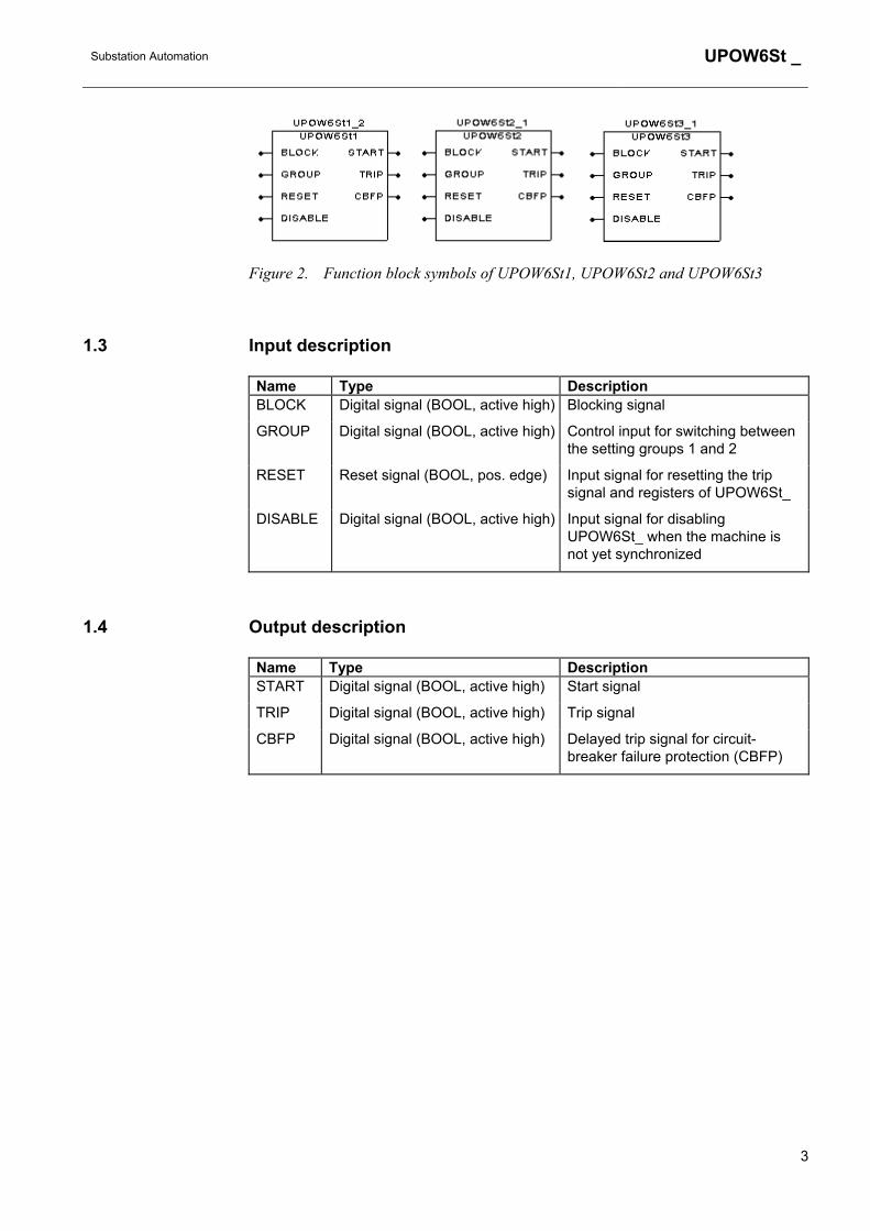
Figure 2. Function block symbols of UPOW6St1, UPOW6St2 and UPOW6St3
1.3 Input description
Name Type Description BLOCK Digital signal (BOOL, active high) Blocking signal
GROUP Digital signal (BOOL, active high) Control input for switching between the setting groups 1 and 2
RESET Reset signal (BOOL, pos. edge) Input signal for resetting the trip signal and registers of UPOW6St_
DISABLE Digital signal (BOOL, active high) Input signal for disabling UPOW6St_ when the machine is not yet synchronized
1.4 Output description
Name Type Description START Digital signal (BOOL, active high) Start signal
TRIP Digital signal (BOOL, active high) Trip signal
CBFP Digital signal (BOOL, active high) Delayed trip signal for circuit-breaker failure protection (CBFP)
3
UPOW6St _
Substation Automation
2. Description of operation
2.1 Configuration
Phase currents can be measured by means of conventional current transformers or Rogowski coils and voltages by means of conventional voltage transformers or voltage dividers. The analogue inputs are configured in the Relay Configuration Tool included in the CAP 505 Tool Box. A special dialogue box in the configuration tool is also used for selecting the analogue input combination used for power measurement.
2.1.1 Correction parameters for measuring devices
Where a low value of reverse power setting is required, e.g. 2%, and the primary circuit operating values must not deviate significantly from this, the correction parameters have be used in the relay to compensate for the measuring errors. The manufacturer of the measuring devices is to be contacted to obtain information on the measuring errors.
If the measuring errors are not compensated for, the underpower setting should not be lower than the sum of the current and voltage measuring errors. For example, if the error of the current measuring device is 2 % and that of the voltage measuring device 1 %, the minimum setting is ( 2 + 1 ) % = 3 %.
The correction parameters for measuring devices can be set in the Relay Configuration Tool as well as via the MMI of the machine terminal. For more information on setting the correction parameters refer to the Technical Reference Manual of REM 543.
2.1.2 Analogue input selection for configuration
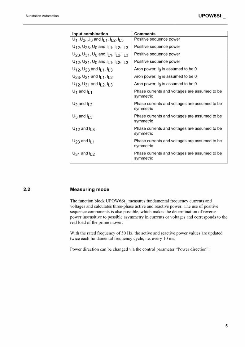
The analogue input combinations listed below are available in the dialogue box of the configuration tool. When all the phase currents and phase voltages are known, P and Q are calculated from positive-sequence components. The correct input combination is selected via the configuration tool.
4
Substation Automation
UPOW6St _
Input combination Comments U1, U2, U3 and IL1, IL2, IL3 Positive sequence power
U12, U23, U0 and IL1, IL2, IL3 Positive sequence power
U23, U31, U0 and IL1, IL2, IL3 Positive sequence power
U12, U31, U0 and IL1, IL2, IL3 Positive sequence power
U12, U23 and IL1, IL3 Aron power; I0 is assumed to be 0
U23, U31 and IL1, IL2 Aron power; I0 is assumed to be 0
U12, U31 and IL2, IL3 Aron power; I0 is assumed to be 0
U1 and IL1 Phase currents and voltages are assumed to be symmetric
U2 and IL2 Phase currents and voltages are assumed to be symmetric
U3 and IL3 Phase currents and voltages are assumed to be symmetric
U12 and IL3 Phase currents and voltages are assumed to be symmetric
U23 and IL1 Phase currents and voltages are assumed to be symmetric
U31 and IL2 Phase currents and voltages are assumed to be symmetric
2.2 Measuring mode
The function block UPOW6St_ measures fundamental frequency currents and voltages and calculates three-phase active and reactive power. The use of positive sequence components is also possible, which makes the determination of reverse power insensitive to possible asymmetry in currents or voltages and corresponds to the real load of the prime mover.
With the rated frequency of 50 Hz, the active and reactive power values are updated twice each fundamental frequency cycle, i.e. every 10 ms.
Power direction can be changed via the control parameter “Power direction”.
5

UPOW6St _
Substation Automation
2.3 Operation criteria
UPOW6St_ can be set to monitor either reverse power or low forward power via the setting parameter “Operation mode”. The function block starts if the measured power drops below the operating line.
.
P
Q
Hys
tere
sis
O
p
e
r
a
t
e
s
Figure 3. The operating characteristic of UPOW6St_ when the operation mode is "reverse power"
P
Q
Hyst
eres
is
O
p
e
r
a
t
e
s
Figure 4. The operating characteristic of UPOW6St_ when operation mode is "underpower"
When the parameter “Disable mode” is ON, the function block cannot operate if the DISABLE input is active. When the DISABLE input is deactivated, the function block still remains disabled for the time defined in the “Wait time” parameter. The DISABLE input must be connected negated to the status of the circuit breaker. The “Wait time” parameter and the DISABLE input are used when synchronizing the generator.
When the parameter “Disable mode” is OFF, the DISABLE input has no effect.
6

Substation Automation
UPOW6St _
Figure 5. Example of configuration when the DISABLE input is used
�
�����������
�
�� ��������� ���
�����
����������
�����
����
� �����
���� �� ������
Figure 6. Meaning of the DISABLE input and “Wait time” parameter when “Disable mode”= ON
�
�����������
�
�� ������������
�����
����������
�����
����
Figure 7. Operation is allowed all the time and the “Wait time” parameter has no effect if the “Disable mode”= OFF
2.4 Delayed reset facility and drop-off time in DT Mode
At reciprocating load conditions, the power measuring element may pick up briefly and periodically. The purpose of the delayed reset function is to ensure that the function block operates within its predetermined operating time even in such power swing conditions. Without the delayed reset function the DT timer would reset as soon as the measuring element drops off.
7

UPOW6St _
Substation Automation
When the DT timer has started, it goes on running normally even if the measuring element drops off, provided the drop-off period is shorter than the set drop-off time. If the drop-off period is longer than the set drop-off time, the DT timer will reset when the drop-off time elapses (Figure 8).
In Figures 8 and 9 the input signal IN of the DT timer is TRUE when the measured power is below the set start value and FALSE when the measured power is above the set start value.
Operate time
Drop-off time
IN
START
TRIP
0
1
Drop-offtimer
Operatetimer
Dro
poff1
.fh7
Figure 8. The drop-off period is longer than the set drop-off time
If the drop-off period is shorter than the set drop-off time and the DT timer has elapsed during the drop-off period, the function block will trip once the measured power drops below the set start value again (Figure 9).
Operate time
Drop-off time
IN
START
TRIP
0
1
Drop-offtimer
Operatetimer D
ropo
ff2.fh
7
Figure 9. The drop-off period is shorter than the set drop-off time
2.5 Setting groups
Two different groups of setting values, group 1 and group 2, are available for the function block. Switching between the two groups can be done in the following three ways:
8

Substation Automation
UPOW6St _
1 Locally with the control parameter “Group selection”1) on the MMI 2 Over the communication bus by writing the parameter V51) 3 By means of the input signal GROUP when allowed via the parameter “Group
selection” (i.e. when V5 = 21)) 1) Group selection (V5): 0 = Group 1; 1 = Group 2; 2 = GROUP input
The control parameter “Active group” indicates the setting group valid at a given time.
2.6 Test mode
The digital outputs of the function block can be activated with separate control parameters for each output either locally via the MMI or externally via the serial communication. When an output is activated with the test parameter, an event indicating the test is generated.
The protection functions operate normally while the outputs are tested.
2.7 START, TRIP and CBFP outputs
The output signal START is always pulse-shaped. The minimum pulse width of the corresponding output signal is set with a separate parameter on the MMI or on serial communication. If the start situation is longer than the set pulse width, the START signal remains active until the start situation is over. The output signal TRIP may have a non-latching or latching feature. When the latching mode has been selected, the TRIP signal remains active until the output is reset even if the operation criteria have reset.
The function block provides a delayed trip signal CBFP after the TRIP signal unless the fault has disappeared during the set CBFP time delay. In circuit-breaker failure protection the CBFP output can be used to operate a circuit breaker in front of the circuit breaker of the machine. The control parameter “Trip pulse” also sets the width of the CBFP output signal.
9

UPOW6St _
Substation Automation
2.8 Resetting
The TRIP output signal and the registers can be reset via the RESET input, or over the serial bus or the local MMI.
The operation indicators, latched trip signal and recorded data can be reset as follows:
Operation indicators
Latched trip signal
Recorded data
RESET input of the function block 1) X X
Parameter F095V013 for UPOW6St11) X X
Parameter F096V013 for UPOW6St21) X X
Parameter F097V013 for UPOW6St31) X X
General parameter F001V011 2) X
General parameter F001V012 2) X X
General parameter F001V013 2) X X X
Push-button C 2) X
Push-buttons C + E (2 s) 2) X X
Push-buttons C + E (5 s) 2) X X X 1) Resets the latched trip signal and recorded data of this particular function block. 2) Affects all function blocks.
10

Substation Automation
UPOW6St _
3. Parameters and events
3.1 General
• Each function block has a specific channel number for serial communication parameters and events. The channel for UPOW6St1 is 95, that for UPOW6St2 96 and that for UPOW6St3 97.
• The data direction of the parameters defines the use of each parameter as follows: Data direction Description R, R/M Read only
W Write only
R/W Read and write
• The different event mask parameters (see section “Control settings”) affect the visibility of events on the MMI or on serial communication (LON or SPA) as follows: Event mask 1 (FxxxV101/102) SPA / MMI (LON)
Event mask 2 (FxxxV103/104) LON
Event mask 3 (FxxxV105/106) LON
Event mask 4 (FxxxV107/108) LON
For example, if only the events E3, E4 and E5 are to be seen on the MMI of the relay terminal, the event mask value 56 (8 + 16 + 32) is written to the “Event mask 1” parameter (FxxxV101). In case a function block includes more than 32 events, there are two parameters instead of e.g. the “Event mask 1” parameter: the parameter “Event mask 1A” (FxxxV101) covers the events 0...31 and “Event mask 1B”(FxxxV102) the events 32...63.
11

UPOW6St _
Substation Automation
3.2 Setting values
3.2.1 Actual settings
Parameter Code Values Unit Default Data direction
Explanation
Power setting S1 1.0...200.0 % Sn 1.0 R Start power
Operation mode S2 0 or 1 1) - 1 R Selection of underpower or reverse power
Operate time S3 0.04...300.00 s 0.5 R Operate time
Wait time S4 0.0...60.0 s 0.0 R Waiting time after closing a circuit breaker
Disable mode S5 0 or 1 2) - 1 R Disable input in use or not in use 1) Operation mode 0 = Underpower; 1 = Reverse power 2) Disable mode 0 = OFF; 1 = ON
3.2.2 Setting group 1
Parameter Code Values Unit Default Data direction
Explanation
Power setting S41 1.0...200.0 % Sn 1.0 R/W Start power
Operation mode S42 0 or 1 1) - 1 R/W Selection of underpower or reverse power
Operate time S43 0.04...300.00 s 0.5 R/W Operate time
Wait time S44 0.0...60.0 s 0.0 R/W Waiting time after closing a circuit breaker
Disable mode S45 0 or 1 2) - 1 R/W Disable input in use or not in use 1) Operation mode 0 = Underpower; 1 = Reverse power 2) Disable mode 0 = OFF; 1 = ON
3.2.3 Setting group 2
Parameter Code Values Unit Default Data direction
Explanation
Power setting S71 1.0...200.0 % Sn 1.0 R/W Start power
Operation mode S72 0 or 1 1) - 1 R/W Selection of underpower or reverse power
Operate time S73 0.04...300.00 s 0.5 R/W Operate time
Wait time S74 0.0...60.0 s 0.0 R/W Waiting time after closing a circuit breaker
Disable mode S75 0 or 1 2) - 1 R/W Disable input in use or not in use 1) Operation mode 0 = Underpower; 1 = Reverse power 2) Disable mode 0 = OFF; 1 = ON
12

Substation Automation
UPOW6St _
3.2.4 Control settings
Parameter Code Values Unit Default Data direction
Explanation
UPOW6St# 1) V1 0 or 1 2) - 1 R/W UPOW6St_ in use or not in use
Drop-off time V2 0.00...60.00 s 1.00 R/W Resetting time of the operate time counter
Measuring mode V3 0...13 3) - 0 R Power measurement mode
Power direction V4 0 or 1 4) - 0 R/W Direction of power flow
Group selection V5 0...2 5) - 0 R/W Selection of the active setting group
Active group V6 0 or 1 6) - 0 R/M Active setting group
Start pulse V7 0...1000 ms 0 R/W Minimum pulse width of START signal
Trip signal V8 0 or 1 7) - 0 R/W Selection of latching feature for TRIP output
Trip pulse V9 40...1000 ms 40 R/W Minimum pulse width of TRIP and CBFP
CBFP time V10 100...1000 ms 100 R/W Operate time of the delayed trip CBFP
Reset registers V13 1=Reset - 0 W Resetting of latched trip signal and registers
Test START V31 0 or 1 8) - - R/W Testing of START
Test TRIP V32 0 or 1 8) - - R/W Testing of TRIP
Test CBFP V33 0 or 1 8) - - R/W Testing of CBFP
Event mask 1 V101 0...4095 - 63 R/W Event mask 1 for event transmission (E0 ... E11)
Event mask 2 V103 0...4095 - 63 R/W Event mask 2 for event transmission (E0 ... E11)
Event mask 3 V105 0...4095 - 63 R/W Event mask 3 for event transmission (E0 ... E11)
Event mask 4 V107 0...4095 - 63 R/W Event mask 4 for event transmission (E0 ... E11)
1) Parameter # denotes the stage number of the function block (1, 2 or 3) 2) Status 0 = Not in use; 1 = In use
3) Measuring mode 0 = Not in use; 1 = U1,U2,U3 & I1,I2,I3; 2=U12,U23,U0 & I1,I2,I3; 3 = U23,U31,U0 & I1,I2,I3; 4 = U12,U31,U0 & I1,I2,I3; 5 = U12,U23 & I1,I2,I3; 6 = U23,U31 & I1,I2,I3; 7= U12,U31 & I1,I2,I3; 8 = U1 & I1; 9 = U2 & I2; 10 = U3 & I3; 11 = U12 & I3; 12 = U23 & I1; 13 = U31 & I2 4) Power direction 0 = Forward; 1 = Reverse
5) Group selection 0 = Group 1; 1 = Group 2; 2 = GROUP input 6) Active group 0 = Group 1; 1 = Group 2 7) Trip signal 0 = Non-latching; 1 = Latching 8) Test 0 = Do not activate; 1 = Activate
13
UPOW6St _
Substation Automation
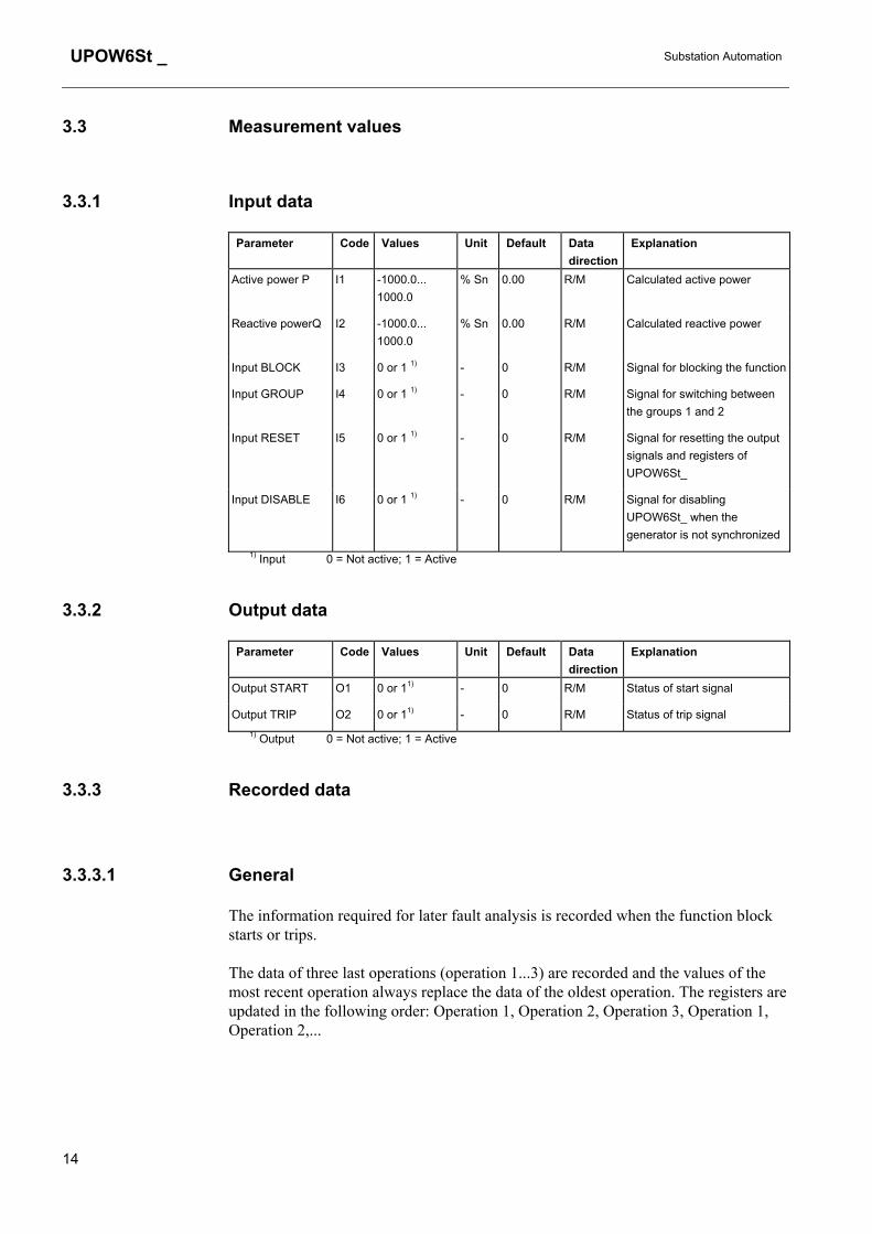
3.3 Measurement values
3.3.1 Input data
Parameter Code Values Unit Default Data direction
Explanation
Active power P I1 -1000.0... 1000.0
% Sn 0.00 R/M Calculated active power
Reactive powerQ I2 -1000.0... 1000.0
% Sn 0.00 R/M Calculated reactive power
Input BLOCK I3 0 or 1 1) - 0 R/M Signal for blocking the function
Input GROUP I4 0 or 1 1) - 0 R/M Signal for switching between the groups 1 and 2
Input RESET I5 0 or 1 1) - 0 R/M Signal for resetting the output signals and registers of UPOW6St_
Input DISABLE I6 0 or 1 1) - 0 R/M Signal for disabling UPOW6St_ when the generator is not synchronized
1) Input 0 = Not active; 1 = Active
3.3.2 Output data
Parameter Code Values Unit Default Data direction
Explanation
Output START O1 0 or 11) - 0 R/M Status of start signal
Output TRIP O2 0 or 11) - 0 R/M Status of trip signal 1) Output 0 = Not active; 1 = Active
3.3.3 Recorded data
3.3.3.1 General
The information required for later fault analysis is recorded when the function block starts or trips.
The data of three last operations (operation 1...3) are recorded and the values of the most recent operation always replace the data of the oldest operation. The registers are updated in the following order: Operation 1, Operation 2, Operation 3, Operation 1, Operation 2,...
14

Substation Automation
UPOW6St _
3.3.3.2 Date and time
The time stamp indicates the rising edge of the START or TRIP signal.
3.3.3.3 Duration
The duration of the start situation is recorded as a percentage of the set operate time.
3.3.3.4 Power
If the function block trips, the power values are updated at the moment of tripping i.e. on the rising edge of the TRIP signal. If the function block starts but does not trip, the power values captured one fundamental cycle (20 ms at rated frequency 50 Hz) after the beginning of the start situation are recorded. Consequently, the active and reactive power values P and Q always originate from the same moment and are recorded as multiples of the rated power Sn.
3.3.3.5 Status data
The status data of the input signal BLOCK (Active or Not active) and the “Active group” parameter are recorded at the moment of triggering. The “Active group” parameter indicates the setting group valid for the recorded data.
3.3.3.6 Priority
The priority of the recording function is the following:
1 Tripping 2 Starting
15

UPOW6St _
Substation Automation
3.3.3.7 Recorded data 1
Parameter Code Values Unit Default Data direction
Explanation
Date V201 YYYY-MM-DD - - R/M Recording date
Time V202 hh:mm:ss.mss - - R/M Recording time
Duration V203 0.0...100.0 % 0.0 R/M Duration of start situation
Active power P V204 -1000.0...1000.0 % Sn 0.00 R/M Calculated active power
Reactive powerQ V205 -1000.0...1000.0 % Sn 0.00 R/M Calculated reactive power
BLOCK V206 0 or 1 1) - 0 R/M Status of BLOCK input
Active group V207 0 or 1 2) - 0 R/M Active setting group 1) BLOCK 0 = Not active; 1 = Active 2) Active group 0 = Group 1; 1 = Group 2
3.3.3.8 Recorded data 2
Parameter Code Values Unit Default Data direction
Explanation
Date V301 YYYY-MM-DD - - R/M Recording date
Time V302 hh:mm:ss.mss - - R/M Recording time
Duration V303 0.0...100.0 % 0.0 R/M Duration of start situation
Active power P V304 -1000.0...1000.0 % Sn 0.00 R/M Calculated active power
Reactive powerQ V305 -1000.0...1000.0 % Sn 0.00 R/M Calculated reactive power
BLOCK V306 0 or 1 1) - 0 R/M Status of BLOCK input
Active group V307 0 or 1 2) - 0 R/M Active setting group 1) BLOCK 0 = Not active; 1 = Active 2) Active group 0 = Group 1; 1 = Group 2
16

Substation Automation
UPOW6St _
3.3.3.9 Recorded data 3
Parameter Code Values Unit Default Data direction
Explanation
Date V401 YYYY-MM-DD - - R/M Recording date
Time V402 hh:mm:ss.mss - - R/M Recording time
Duration V403 0.0...100.0 % 0.0 R/M Duration of start situation
Active power P V404 -1000.0...1000.0 % Sn 0.00 R/M Calculated active power
Reactive powerQ V405 -1000.0...1000.0 % Sn 0.00 R/M Calculated reactive power
BLOCK V406 0 or 1 1) - 0 R/M Status of BLOCK input
Active group V407 0 or 1 2) - 0 R/M Active setting group 1) BLOCK 0 = Not active; 1 = Active 2) Active group 0 = Group 1; 1 = Group 2
3.3.4 Events
Code Weighting coefficient
Default mask
Event reason Event state
E0 1 1 START signal from P< stage 1, 2 or 3 Reset
E1 2 1 START signal from P< stage 1, 2 or 3 Activated
E2 4 1 TRIP signal from P< stage 1, 2 or 3 Reset
E3 8 1 TRIP signal from P< stage 1, 2 or 3 Activated
E4 16 1 CBFP signal from P< stage 1, 2 or 3 Reset
E5 32 1 CBFP signal from P< stage 1, 2 or 3 Activated
E6 64 0 BLOCK signal of P< stage 1, 2 or 3 Reset
E7 128 0 BLOCK signal of P< stage 1, 2 or 3 Activated
E8 256 0 Test mode of P< stage 1, 2 or 3 Off
E9 512 0 Test mode of P< stage 1, 2 or 3 On
E10 1024 0 DISABLE signal of P< stage 1, 2 or 3 Reset
E11 2048 0 DISABLE signal of P< stage 1, 2 or 3 Activated
17

UPOW6St _
Substation Automation
4. Technical data Operation accuracies ± 1.0 % of set value or ± 0.01 x rated value
or
± 1.5 % of set value or ± 0.015 x rated value, when resistive voltage dividers are used
Start time Injected power < 0.5 x Power setting (Operation mode = underpower) or 2.0 x Power setting (Operation mode = reverse power):
f/fn = 0.95...1.05 internal time < 32 ms
total time1) < 40 ms
Reset time 70...1030 ms (depends on the minimum pulse width set for the TRIP output)
Reset ratio Typ. 0.98 (range 0.8...0.98) when Operation mode = reverse power
Typ. 1.02 (range 1.2...1.02) when Operation mode = underpower
Retardation time Total retardation time when the power exceeds the the value set for the “Power setting” parameter
< 45 ms2)
Operate time accuracy Depends on the frequency of the current and voltage measured:
f/fn = 0.95...1.05: ± 2% of set value or ± 20 ms2)
Configuration data Task execution interval (Relay Configuration Tool): 10 ms at the rated frequency fn = 50 Hz
1) Includes the delay of the signal relay 2) Includes the delay of the heavy-duty output relay
Technical revision history Technical revision Change D -
E -
18


