
Instrument Test Interval Determination Curves Probability ...
30
m b PBAPS UNIT 3 i . ' LIST OF FIGURES Figure Title Page 1.1-1 APRM Flow Bias Scram Relationship To Normal 16 Operating conditions - 4.1.1 Instrument Test Interval Determination Curves 55 4.2.2 Probability of System Unavailability vs. Test 98 Interval 3.4.1 DELETED 122 3.4.2 DELETED 123 3.5.K.1 MCPR Operating Limit vs. Tau, BP/P8X8R, LTA, 142 GE8X8EB Fuel, Standard Operating Conditions j 3.5.K.2 MCPR Operating Limit vs. Tau, BP/P8X8R, 142a LTA, GE8X8EB Fuel, Increased Core Flow ' 3.5.1.A DELETED 3.5.1.B DELETED 3.5.1.C DELETED 3.5.1.D DELETED 3.5.1.E Kf Factor vs. Core Flow 142d 3.5.1.F MAPLHGR vs. Planar Average Exposure, Unit 3, 142e GE8X8EB Fuel (Type BD319A) 3.5.1.G MAPLHGR vs. Planar Average Exposure, Unit 3, 142f GE8X8EB Fuel (Type BD321A) 3.5.1.H MAPLHGR vs. Planar Average Exposure, Unit 3, 142g P8X8R Fuel (P8DRB284H) 3.5.1.I MAPLHGR vs. Planar Average Exposure, Unit 3, 142h P8X8n and BP8X8R Fuel (P8DRB299 and BP8DRB299) 3.5.1.J MAPLHGR vs. Planar Average Exposure, Unit 3, 1421 BP8X8R Fuel (BP8DRB2991) 3.5.1.K MAPLHGR vs. Planar Average Exposure, Unit 3, 142j P8X8Q LTA (P8DQB326) 3.6.1 Minimum Temperature for Pressure Tests 164 such as required by Section XI 3.6.2 Minimum Temperature for Mechanical Heatup or 164a Cooldown following Nuclear Shutdown 3.6.3 Minimum Temperature for Core Operation 164b (Criticality) 3.6.4 Transition Temperature Shift vs. Fluence 164c 3.6.5 Thermal Power Limits of Specifications 164d 3.6.F.3, 3.6.F.4, 3.6.F.5, 3.6.F.6 and 3.6.F.7 3.8.1 Site Boundary and Effluent Release Points 216e 6.2-1 Management Organization Chart 244 6.2-2 Organization for Conduct of Plant Operation 245 -iv- 8807150229 eco7o7 PDR ADOCK 05000273 P PDC
Transcript of Instrument Test Interval Determination Curves Probability ...

m
b
PBAPS UNIT 3i .'
LIST OF FIGURES
Figure Title Page
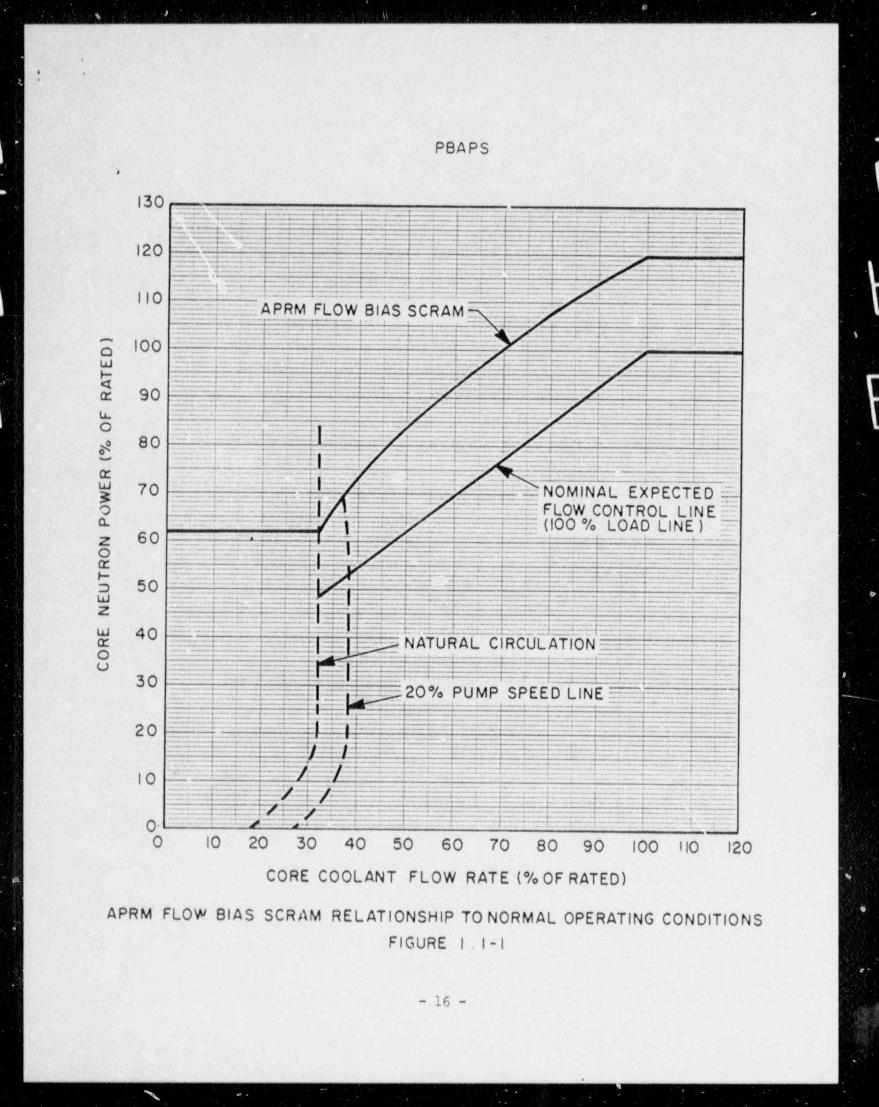
1.1-1 APRM Flow Bias Scram Relationship To Normal 16Operating conditions -
4.1.1 Instrument Test Interval Determination Curves 554.2.2 Probability of System Unavailability vs. Test 98
Interval3.4.1 DELETED 1223.4.2 DELETED 1233.5.K.1 MCPR Operating Limit vs. Tau, BP/P8X8R, LTA, 142
GE8X8EB Fuel, Standard Operating Conditions j3.5.K.2 MCPR Operating Limit vs. Tau, BP/P8X8R, 142aLTA, GE8X8EB Fuel, Increased Core Flow '
3.5.1.A DELETED3.5.1.B DELETED3.5.1.C DELETED3.5.1.D DELETED3.5.1.E Kf Factor vs. Core Flow 142d3.5.1.F MAPLHGR vs. Planar Average Exposure, Unit 3, 142e
GE8X8EB Fuel (Type BD319A)3.5.1.G MAPLHGR vs. Planar Average Exposure, Unit 3, 142f
GE8X8EB Fuel (Type BD321A)3.5.1.H MAPLHGR vs. Planar Average Exposure, Unit 3, 142g
P8X8R Fuel (P8DRB284H)3.5.1.I MAPLHGR vs. Planar Average Exposure, Unit 3, 142h
P8X8n and BP8X8R Fuel (P8DRB299 and BP8DRB299)3.5.1.J MAPLHGR vs. Planar Average Exposure, Unit 3, 1421
BP8X8R Fuel (BP8DRB2991)3.5.1.K MAPLHGR vs. Planar Average Exposure, Unit 3, 142j
P8X8Q LTA (P8DQB326)3.6.1 Minimum Temperature for Pressure Tests 164
such as required by Section XI3.6.2 Minimum Temperature for Mechanical Heatup or 164a
Cooldown following Nuclear Shutdown3.6.3 Minimum Temperature for Core Operation 164b
(Criticality)3.6.4 Transition Temperature Shift vs. Fluence 164c3.6.5 Thermal Power Limits of Specifications 164d
3.6.F.3, 3.6.F.4, 3.6.F.5, 3.6.F.6 and 3.6.F.73.8.1 Site Boundary and Effluent Release Points 216e6.2-1 Management Organization Chart 2446.2-2 Organization for Conduct of Plant Operation 245
-iv-
8807150229 eco7o7PDR ADOCK 05000273P PDC

.
PBAPS. .
1.0 DEFINITIONS
The succeeding frequently used terms are explicitly defined sothat a uniform interpretation of the specifications may beachieved.
Alteration of the Reactor Core - The act of moving any componentin the region above the core support plate, below the upper gridand within the shroud with the vessel head, removed and fuel inthe vessel.
Normal control rod movement with the control drive hydraulicsystem is not defined as a core alteration. Normal movement ofin-core instrumentation and the traversing in-core probe is notdefined as a core alteration.
Average Planar Linear Heat Generation Rate LAPLHGR) - The APLHGRshall be applicable to a specific planar he:.ght and is equal tothe sum of the heat generation rate per unit length of fuel rod,for all the fuel rods in the specific bundle at the specificheight, divided by the number of fuel rods in the fuel bundle atthat height.
..
Channel - A channel is an arrangement of a sensor and associatedcomponents used to evaluate plant variables and produce discreteoutputs used in logic. A channel terminates and loses itsidentity where individual channel outputs are combined in logic.
Cold Condition - Reactor coolant temperature equal to or lessthan 212 F.
Cold shutdown - The reactor ir. in the shutdown mode, the reactorcoolant temperature equal to or less than 212 F, and the reactorvossel is vented to atmosphere.
Critical Power Ratio (C?R) - The critical power ratio is theratio of that assembly power which causes some point in theassembly to experience transition boiling to the assembly powerat the reactor condition of interest as calculated by applicationof the GEXL correlacion. (Reference NSDO-10958). ;
Dose Equivalent I-131 - That concentration of I-131 (Ci/gm)which alone would produce the same thyroid dose as the quantityand isotopic mixture of I-131, I-132, I-133, I-134, and I-135 ;
actually present.
-1-
_.

'
Unit 3,
PBAPS
SAFETY LIMIT LIMITING SAFETY SYSTEM SETTING1.1 FUEL CLADDING INTEGRITY 2.1 FUFL CLADDING INTEGRITYApplicability: Applicabfilty:The Safety Limits established The Limitirig Safety System Settingsto preserve the fuel cladding apply to t::ip settings of theintegrity apply to those instruments and devices which arevariables which monitor the provided to prevent the fuelfuel thermal behavior, cladding integrity Safety Limits
from being exceeded.Objectives: Objective 3:
The objective of the Safety The objective of the Limiting SafetyLimits is to establish limits System Se ttings is to define thewhich assure the integrity of level of the process variables atthe fuel cladding. which automatic protective action is
initiated to prevent the fuel claddingintegrity Safety Limits from beingexceeded.
Specification: Specification:
A. Reactor Pressure E 800 psia The limiting safety system settingsand Core Flow h 10% of Rated shall be as specified below:
A. Neutron Flux Scram
The existence of a minimum 1. APRM Flux Scram Trip Settingcritical power ratio (MCPR) (Run Mode)less than 1.04 for tworecirculation loop operation, When the Mode Switch is in theor 1.05 for single loop | RUN position, the APRM fluxoperation, shall constitute scram trip setting shall be:violation of the fuel claddingintegrity safety limit. S < 0.58W + 62% - 0.58 dW |
To ensure that this safety where:limit is not exceeded, neutronflux shall not be above the S = Setting in percent of ratedscram setting established in thermal power (3293 MWt)specification 2.1.A for longerthan 1.15 seconds as indicated W = Loop recirculating,
i by the process computer. When flow rate in percentt
the process computer is out of of design. W is 100 for| service this safety limit shall core flow of 102.5
be assumed to be exceeded if million lb/hr or greater.the neutron flux exceeds itsscram setting and a control
| rod scram does not occur.
| -9-
- . . . _ .

Unit 3'
: *
PBAPS
SAFETY LIMIT LIMITING SAFETY SYSTEM SETTING1.1 FUEL CLADDING INTEGRITY 2.1 PUEL CLADDING INTEGRITY
o W = Difference between twoloop and single loopeffective recirculationdrive flow rate at thesame core flow. During,
single loop operation, thereduction in trip setting '
(-0. 58 4 W) is accomplished |by correcting the flowinput of the flow biasedscram to preserve theoriginal (two loop)relationship between APRMscram setpoint andrecirculation drive flowor by adjusting the APRMflux trip setting.AW = 0 for two loop operation.
-9a-

. _
!PBAPS UNIT 3 ),
Y j*
SAFETY LIMIT LIMITING SAFETY SYSTEM JETTING |
\
2.1.A (Cont'd)
In the event of operationwith a maximum fraction oflimiting power density (MFLPD)greater than the. fraction.ofrated power (FRP), the settingshall be modified as follows.
S< (0.58W + 62% - 0.58 AW) (FRPL |MFLPD
where,
FRP = fraction of rated thermalpower (3293 MWt) '
MFLPD = maximum fraction oflimiting power densitywhere the limitingpower density is 13.4KW/ft for BP/P8X8R and LTAfuel aild 14.4 KW/ft forGE8X8EB fuel.
The ratio of FRP to MFLPDshall be set equal to 1.0 unlessthe actual operating valueis less than the design valueof 1.0, in which case the actualoperating value will be used.
2. APRM--When the reactor modeswitch is in the STARTUPposition, the APRM scram shallbe set at less ts.Jn orequal to 15 percent of
N, rated power.N.
's 3. IRM--The IRM scram shall be'
set at less than or equal to120/125 of full scale.
|1
-10-
E._

.
* *-PBAPS
SAFETY LIMIT LIMITING SAFETY SYSTEM SETTING'
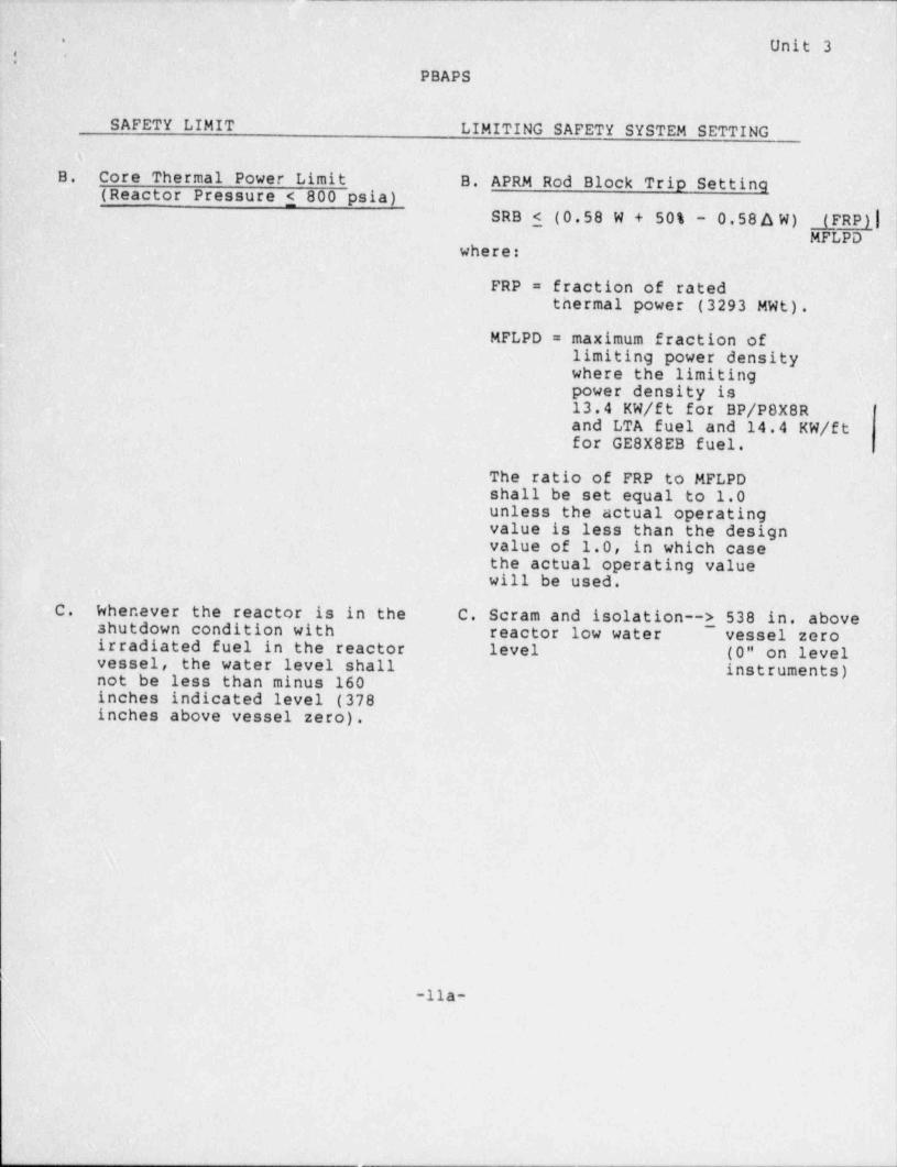
B. Core Thermal Power Limit B. APRM Rod Block Trip Setting(Reactor Pressure < 800 psia)
When the reactor pressure is SRB <- (0.58 W + 50% - 0.58o W) |< 800 psia or. core flow isless than 10% of rated, the where:core thermal power shall notexceed 25% of rated thermal SRB = Rod block setting inpower. percent of rated thermal
power (3293 MWt)
W = Loop recirculation flowrate in percent of design.W is 100 for core flow of102.5 million lb/hr orgreater.
AW = Difference between twoloop and single loopeffective recirculationdrive flow at the samecore flow. During l
single loop operation,the reduction in tripsetting (-0.58 o W) is |accomplished by correctingthe flow input of theflow biased rod block topreserve the original(two loop) relationshipbetween APRM Rod blocksetpoint and recirculationdrive flow or by adjustingthe APRM Rod block trip setting.AW = 0 for two loopoperation.
In the event of operation withmaximum fraction limiting powerdensity (MFLPD) greater than thefraction of rated power (FRP),the setting shall be modified asfollows.
-11-
... - .- . .. --, - - . . - .
..
Unit 3.; .
PBAPS
SAFETY LIMIT LIMITING SAFETY SYSTEM SETTINGs-
B. . Core Thermal Power Limit B. APRM Rod Block Trip Setting(Reactor Pressure 5 800 psia)
SRB $ (0.58 W + 50% - 0.58 A W) (FRP)|MFLPD
where:i
FRP = fraction of ratedthermal power (3293 MWt).
MFLPD = maximum fraction oflimiting power densitywhere the limitingpower density is13.4 KW/ft for BP/P8X8Rand LTA fuel and 14.4 KW/ftfor GE8X8EB fuel.
The ratio of FRP to MFLPDshall be set equal to 1.0unless the actual operatingvalue is less than the designvalue of 1.0, in which casethe actual operating valuewill be used.
.
C. Whenever the reactor is in the C. Scram and isolation--> 538 in, aboveshutdown condition with reactor low water vessel zero
~
irradiated fuel in the reactor level (0" on levelvessel, the water level shall instruments)not be less than minus 160inches indicated level (378inches above vessel zero).
-lla-
,. _ - - . - - - - -
.
; .
|
1.1 BASES: FUEL CLADDING INTEGRITY
A. Fuel Cladding Integrity Limit at Reactor Pressure > 800|psia and Core Flow > 10% of Rated
The fuel cladding integrity safety limit is set such that nofuel damage is calculated to occur if the limit is notviolated. Since the parameters which result in fuel damage arenot directly observable during reactor operation the thermal Ihydraulic conditions resulting in a departure from nucleateboiling have been used to mark the beginning of the regionwhere fuel damage could occur. Although it is recognized thata departure from nucleate boiling would not necessarily resultin damage to BWR fuel rods, the critical power at which bcilingtransition is calculated to occur has been adopted as aconvenient. limit. However, the uncertainties in monitoring thecore operating state and in the procedure used to calculate thecritical power result in an uncertainty in the value of thecritical power. Therefore, the fuel cladding integrity safetylimit is defined as the critical power ratio in the limitingfuel assembly for which more than 99.9% of the fuel rods in thecore are expected to avoid boiling transition considering thepower distribution within the core and all uncertainties.
The Safety Limit MCPR is determined using the General Electric,,
| Thermal Analysis Basis described in references 1 and 3 for two'
recirculation' loop operation. The Safety Limit MCPR isincreased by 0.01 for single-loop operation as discussed in|
reference 4.
h.1
1
1
-13-

.
PBAPS* *
1.1.C BASES (Cont'd.)
However, for this specification a Safety Limit violation will beassumed when a scram is only accomplished by means of a backupfeature of the plant design. The concept of not approaching aSafety Limit, provided scram signals are operable, is supportedby the extensive plant safety analysis.
The computer provided with Peach Bottom Unit 2 has a sequenceannunciation program which will indicate the sequence in which
|events such as scram, APRM trip initiation, pressure scraminitiation, etc. occur. This program also indicates when thescram setpoint is cleared. This will provide information on howlong a scram condition exists and thus provide some measure ofthe energy added during a transient. Thus, computer informationnormally will be available for analyzing scrams; however, if thecomputer information should not be available for any scramanalysis, Specification 1.1.C will be relied upon to determine ifa Safety Limit has been violated.
D. Reactor Water Level (Shutdown Condition)
-During periods when the reactor is shutdown, consideration mustalso be given to water level requirements due to the effect ofdecay heat. If reactor water level should drop below the top ofthe active fuel during this time, the ability to cool the core isreduced. This reduction in core cooling capability could lead toelevated cladding temperatures and clad perforation. The corecan be cooled sufficiently should the water level be reduced totwo-thirds the core height. Establishment of the safety limit atminus 160 inches indicated level (378 inches above vessel zero)provides adequate margin to assure sufficient cooling duringshutdown conditions. This level will be continuously monitored.
E. References
1. General Electric BWR Thermal Analysis Basis (GETAB): Data,i Correlation and Design Application, January 1977 (NEDO-10958-A).
2. Process Computer Performance Evaluation Accuracy, GeneralElectric Company BWR Systems Department, June 1974 (NEDO-20340).
3. "General Electric Standard Application for Reactor Fuel",NEDE-240ll-P-A (as amended).
4. "Peach Bottom Atomic Power Station Units 2 and 3 Single-LoopOperation", NEDO-24229-1, May 1980.
-15-
- _ _ _ _ _ _ _ _ _ _ _ _ _ _ _ _ _ _ _ _ _ _ _ _
||,
; I-
PBAPS|!.,
1 3 0 _ _ _, _. _ _ . _ _ __ ._._ __._
,_
-.. . e=-
\-
12 0 __ n .
" - - ',
,
_ _ _ 2 _ _. _ :.
__,_ ;,
IIO ~~~~ ' 7=4 " ' - ' - - ~" "
- APRM FLOW BIAS SCRAMg_, ,
+ = \,
g I00 r._-- _:__._. T- ~
w t --
H<
| e 90u. +o --- _:F------+ -- --; [
---
'
| g 80.
- - - ~ " '
5 = =s L_._ 1|= = e _ ] .'. _ .. _ . - - - - - - - - - -
'
- i--- . . _ =e = _ + = = - --
~~"'' ~~~~I=._._ U =- .==---
W 70 "-- ~~~ . N OM I N A L EX P ECTE D E.! ! U---I7If/ L _ __-__ FLOW CONTROL LINE E
~-
a. = - _ .. . ;_. . - /.:- (100 % LOAD LINE ) 5-. z 60 _.
~ -- ---~ !_p|_ . .
*
L_ W.| o r_ -- .
.__ =.
.--e -H _
--- | '
o 50 . g -~ ._1 !__
i*
w _ r + ,=.
i l=| : . r-- i---. 9 . i~-
.
-t
g 40 -' ~ 4 '
o -- |g- NhTURAL CIRCDLATION~
' C+ - -' * +- -
["E-|-| u .
304 .= 20% PUMP SPEED LINE.
c_ - + - - -
20 , !Z! d __rj=-j -r
* j j ' -. _D_^2.._._. __ a ._+ ;IO : - x:- ____r.x.rn r_ / ~_ / ^
._ _ L .T__T. |.
. .
0- ~ ~ * -- A -- ~ '... _._ i
- -
-~ ~ ~ - ~ ~ ~ " ~ - ~ ~ ' ~ ~ - - ~ ~ ' ^ ~ ^ ^ "
O 10 20 30 40 50 60 70 80 90 10 0 110 12 0
CORE COOLANT FLOW RATE (% OF RATED) li
APRM FLOW BIAS SCRAM REL ATIONSHIP TO NORMAL OPERATING CONDITIONSFIGURE I l-l
- 16 -
O
*
PBAPS* *
2.1 BASES: FUEL CLADDING INTEGRITY
The abnormal operational transients applicable to operation ofthe Peach Bottom Atomic Power Station Units have been analyzedthroughout the spectrum of planned operating ccnditions up to orabove the thermal power condition required by Regulatory Guide1.49. The analyses were based upon plant operation in accordancewith the operating map given in Figure 3.7.1 of-the FSAR. Inaddition, 3293 MWt is the licensed maximum power level of eachPeach Bottom Atomic Power Station Unit, and this represents themaximum steady state power which shall not knowingly be exceeded.
Conservatism is incorporated in the transient analyses in|estimating the controlling factors, such as void reactivity
coefficient, control rod scram worth, scram delay time, peakingfactors, and axial power shapes. These factors are selectedconservatively with respect to their effect on the applicabletransient results as determined by the current analysis model.Ccnservatism incorporated into the transient analyses isdocumented in NEDE-240ll-P-A (as amended).
|_17
|
;
.

-. -_
PBAPS,
*
2.1 BASES (Cont'd)
For analyses of the thermal consequences of the transients, aMCPR equal to or greater than the operating limit MCPR given inSpecification 3.5.K is conservatively assumed to exist prior toinitiation of the limiting transients. This choice of usingconservative values of controlling parameters and-initiatingtransients at the design power level produces more pessimisticanswers than would result by using expected values of controlparameters and analyzing at higher power levels.
Steady state operation without forced recirculation will not bepermitted. The analysis to support operation at various powerand flow relationships has considered operation with either oneor two recirculating pumps.
In summary:
1. The abnormal operational transients were analyzed at orabove the maximum power level required by Regulatory Guide1.49 to determine operating limit MCPR's.
ii. The licensed maximum power level is 3293 MWt.
iii. Analyses of transients employ adequately conservativevalues of the controlling reactor parameters.
iv. The analytical procedures now used result in a more logicalanswer than the alternative method of assuming a higherstarting power in conjunction with the expected values forthe parameters.
The bases for individual trip settings are discussed in thefollowing paragraphs.
A. Neutron Flux Scram
The-Average Power Range Monitoring (APRM) system, which iscalibrated using heat balance data taken during steady stateconditions, reads in percent of rated thermal power (3293 MWt).Because fission chambers provide the basic input signals, theAPRM system responds directly to average neutron flux. Duringtransients, the instantaneous rate of heat transfer from the fuel(reactor thermal power) is less than the instantaneous neutronflux due to the time constant of the fuel. Therefore, duringabnormal operational transients, the thermal power of the fuelwill be less than that indicated by the neutron flux at the scramsetting. Analyses demonstrate that with a 120 percent scram tripsetting, none of the abnormal operational transients analyzedviolate the fuel Safety Limit and there is a substantial marginfrom fuel damage. Therefore, the use of flow referenced scramtrip provides even additional margin.
-18-
-- . -. - - . - - - - . - - - - _ _ . - - - . . - - , .-

._
PBAPS Unit 34 .,,
2.2 BASES
REACTOR COOLANT SYSTEM INTEGRITY
The pressure relief system for each unit at the Peach BottomAtomic Power Station has been sized to meet two design bases.First, the total capacity of the safety / relief valves and safetyvalves has been established to meet the overpressure protectioncriteria of the ASME Code. Second, the distribution of thisrequired capacity.between safety valves and relief valves hasbeen set to meet design basis 4.4.4.1 of subsection 4.4 of theFSAR which states that the nuclear system safety / relief valvesshall prevent opening of the safety valves during normal plantisolations and load rejections.
The details of the analysis which show compliance with the ASMECode requirements are presented in subsection 4.4 of the PSAR andthe Reactor Vessel Overpressure Protection Summary TechnicalReport submitted in Appendix K.
Eleven safety / relief valves and two safety valves have beeninstalled on Peach Bottom Units 2 and 3. The analysis of the Iworst overpressure transient is provided in the SupplementalReload Licensing _ Submittal and demonstrates margin to the code Iallowable overpressure limit of 1375 psig.
The safety / relief valve settings satisfy the Code requirei..entsthat the lowest valve setpoint be at or below the vessel designpressure of 1250 psig. These settings are also sufficientlyabove the normal operating pressure range to prevent unnecessarycycling caused by minor transients.
The design pressure of the shutdown cooling piping of theResidual Heat Removal System is not exceeded with the reactorvessel steam dome less than 75 psig.
-33-
t

-
- ,
., --
Unit 3.-
. - .
Taole 3.1.1
REACTOR PROTECTION SYSTEM (SCRAM) INSTRUMENTATION REQUIREMENT
Minimum No. Modes in which Number of.of Operable Function'Must be InstrumentInstrument Trip Level Operable Cnannels ActionChannels Trip Function ' Setting Provided- -(1)
' '
per Trio Refuel Startup Run by DesignItcm System (1) (7)
1 1 Mode Switen In X X X 1 Mode Switch AShutdown '-
(4' Sections)
2 1 Manual Scram X X X 2 Instrument 'A
Channels
2 3 IRM High Flux $120/125 of Full X X (5) 8 Instrument AScale Channels
4 3 IRM Inoperative X X (5) 8 Instrument AChanneIs
E
5 2 APRM High Flux (0.58W+62-0.58AW) X 6 Instrument A or B |v'J FRP/MFLPD Channelss (12) (13).
6 2 APRM Inoperative (11) X X X -6 Instrument A or BChannels
7 2 APRM Downscale 12.5 Indicated (10: 6 Instrument A or 8on Scale Channels
8 2 APRM High Flux 115% Power X X 6 In3trument Ain Startup Channels
9 2 High Reactor <1055 psig X(9) X X 4 Instrument APressure Channels
10 2 High Drywell <2 psig X(8) X(8) X 4 Instrument APressure Channels
11 2 Reactor Low 10 in. Indicated X X X 4 Instrument A_.
Water Level Level Channels

. _ _ _ _ _ _
PBAPS Unit 3,
I NOTES FOR TABLE 3.1.1 (Cont'd)'
10. The APRM downscale trip is automatically bypassed when the,IRM instrumentation is operable and not high.
11. An APRM will be considered operable if there are at least 2LPRM inputs per level and at least 14 LPRM inputs of thenormal complement.
12. This equation will be used in the event of operation with amaximum fraction of limiting power density (MFLPD) greaterthan the fraction of rated power (FRP), where:
FRP = fraction of rated thermal power (3293 MWt). |
MFLPD = maximum fraction of limitingpower density where'thelimiting power density is13.4 KW/ft for BP/P8X8R and LTA fueland 14.4 KW/ft for GE8X8EB fuel.
The ratio of FRP to MFLPD shall be set equal to 1.0 unlessthe actual operating value is less than the design value of1.0, in which case the actual operating value will be used.
W= Loop Recirculation flow in percent of design. Wis 100 for core flow of 102.5 million lb/hr orgreater.
Delta W = The difference between two loop and single loopeffective recirculation drive flow rate at thesame core flow. During single loop operation,the reduction in trip setting (-0.58 delta W) is Iaccomplished by correcting the flow input of theflow biased High Flux trip setting to preservethe original (two loop) relationship between
i APRM High Flux setpoint and recirculation driveflow or by adjusting the APRM Flux trip setting.Delta W equals zero for two loop operation.
Trip level setting is in percent of rated power (3293 MWt).
13. See Section 2.1.A.l.
t
-40-
_ - _ _ _ - _ - _ _ _ - _ _ _ _ _ _ _ _ _ - _ _ _ _ _ _ _ _ _ __ _ - _ _ _ _ _

- . _ _ . _
,.-
:
Unit 3''
TABLE'3.2.CINSTRUMENTATION THAT INITIATES CONTROL ROD BLOCKS
Minimum No. Instrument Trip Level Setting- Number of Instrument Actionof OperableChannels Provided -Instrument
Channels Per by Design
Trip System -
4 APRM Upscale (Flow 1(0.58W+50-0.58 A W) x 6 Inst. Channels '(10) |.Biased) FRPMFLPD (2)
.
4 APRM Upscale (Startup 112% 6 Inst. Channels (10)Mode)
4 APRM Downscale 12.5 indicated on 6 Inst. Channels (10)scale
1 (7) Rod Block Monitor 1(0.66w+41-0.66aW)x 2 Inst. Channels (1)(Flow Biased) FRPMFLPD (2)
with a maximum ofi 107%
1 (7) Rod Block Monitor 12.5 indicated on 2 Inst. Channels (1)Downscale scale
1 6 IRM Downscale (3) 12.5 indicated on 8 Inst. Channels (10).a scaleW6 IRM Detector not in (8) 8 Inst. Channels (10)I
Startup Position.
6 IRM Upscale 1108 indicated on 8 Inst. Channels (10)scale'
2 (5) SRM Detector not in (4) 4 Inst. Channels (1)lStartup Position
52 (5)(6) SRM Upscale 110 counts /sec. 4 Inst. Channels (1)1 Scram Discharge 125 gallons 1 Inst. Channel (9)Instrument Volume
High Level|
.

Unit 3i
' '.
PBAPS
NOTES FOR TABLE 3.2.C
1. For the startup and run positions of the Reactor Mode Selector/ Switch, there shall be two operable or tripped trip systems for
each function. The SRM and IRM blocks need not be operable in"Run" mode, and the APRM and RBM rod blocks need not be operablein "Startup" mode. If the first column cannot be met for one of''
the two trip systems, this condition may exist for up to sevendays provided that during that time the operable system isfunctionally tested immediately and daily thereafter; if thiscondition lasts longer than seven days, the system shall betripped. If the first column cannot be met for both tripsystems, the systems shall be tripped.
2. This equation will be used in the event of operation with amaximum fraction of limiting power density (MFLPD) greater thanthe fraction of rated power (FRP) where:
FRP = fraction of rated thermal power (3293 MWt)
MFLPD = maximum fraction of limiting power density where thelimiting power den 3ity is 13.4 KW/ft for BP/P8X8Rand LTA fuel and 14.4 KW/ft for GE8X8EB fuel.
The ratio of FRp to MFLPD shall be set equal to 1.0 unless theactual operating value is less than the design value of 1.0, inwhich case the actual operating value will be used.
W = Loop Recirculation flow in percent of design. W is100 for core flow of 102.5 million lb/hr or greater.
Trip level setting is in percent of rated power (3293 MWt).
A W is the difference between two loop and single loop effectiverecirculation drive flow rate at the same core flow. Duringsingle loop operation, the reduction in trip setting isaccomplished by correcting the flow input of the flow biased rodblock to preserve the original (two loop) relationship betweenthe rod block setpoint and recirculation drive flow, or byadjusting the rod bicek setting. zi W = 0 for two loop operation.
3. IRM downscale is bypassed when it is on its lowest range.4. This function is bypassed when the count rate is > 100 cps.5. One of the four SRM inputs may be bypassed.
6. This SRM function is bypassed when the IRM range switches are onrange 8 or above.
7. The trip is bypassed when the reactor power is < 30%.
8. This function is bypassed when the mode switch is placed in Run.
-74-
1
PBAPS Unit 3,
'
LIMITING CONDITIONS FOR OPERATION SURVEILLANCE REQUIREMENTS
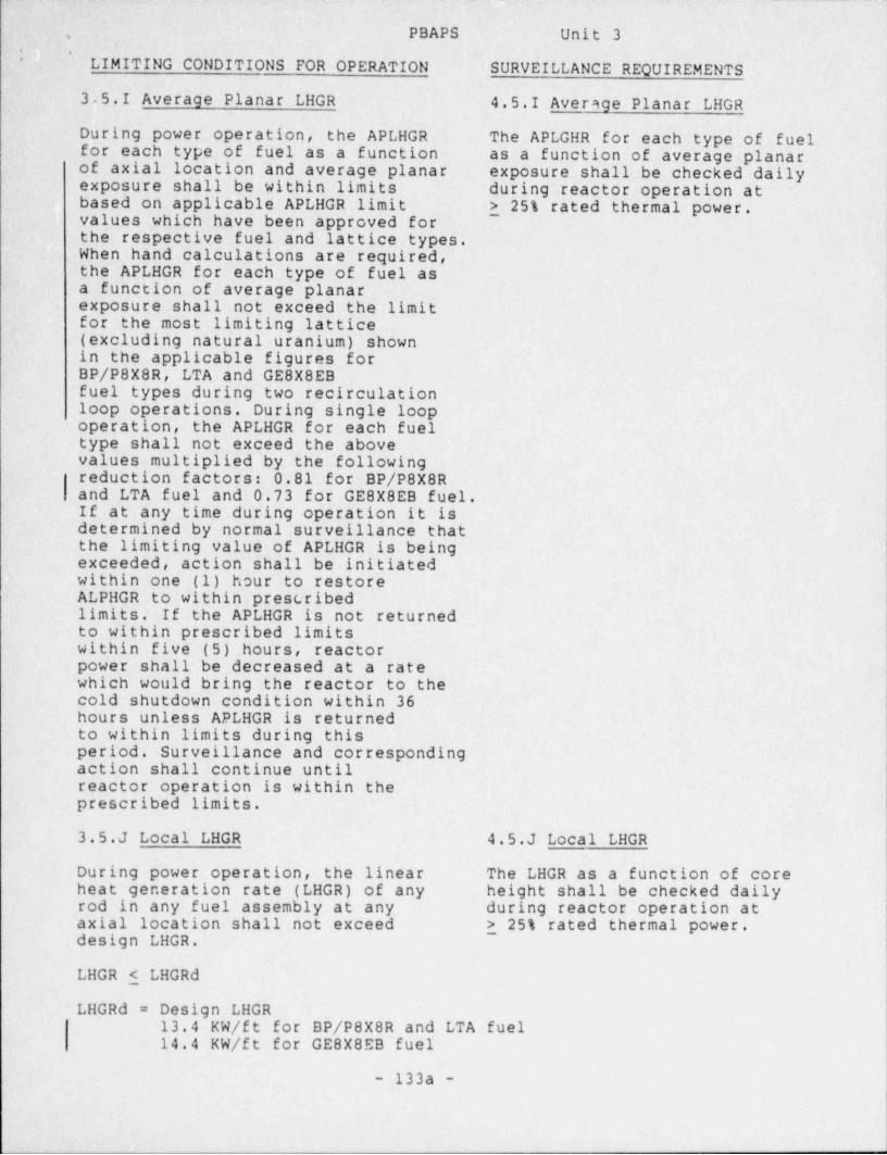
3 5.I Average Planar LHGR 4.5.I Average Planar LHGR
During power operation, the APLHGR The APLGHR for each type of fuelfor each type of fuel as a function as a function of average planarof axial location and average planar exposure shall be checked dailyexposure shall be within limits during reactor operation atbased on applicable ~ APLHGR limit > 25% rated thermal power.values which have been approved forthe respective fuel and lattice types.When hand calculations are required,the APLHGR for_each type of fuel asa function of average planarexposure shall not exceed the limitfor the most limiting lattice(excluding natural uranium) shownin the applicable figures forBP/P8X8R, LTA and GE8X8EBfuel types during two recirculationloop operations. During single loopoperation, the APLHGR for each fueltype shall not exceed the abovevalues multiplied by the followingreduction factors: 0.81 for BP/P8X8Rand LTA fuel and 0.73 for GE8X8EB fuel.If at any time during operation it isdetermined by normal surveillance thatthe limiting value of APLHGR is beingexceeded, action shall be initiatedwithin one (1) hour to restoreALPHGR to within prescribedlimits. If the APLHGR is not returnedto within prescribed limitswithin five (5) hours, reactorpower shall be decreased at a ratewhich would bring the reactor to thecold shutdown condition within 36hours unless APLHGR is returnedto within limits during thisperiod. Surveillance and correspondingaction shall continue untilreactor operation is within theprescribed limits.
3.5.J Local LHGR 4.5.J Local LHGR
During power operation, the linear The LHGR as a function of coreheat generation rate (LHGR) of any height shall be checked dailyrod in any fuel assembly at any during reactor operation ataxial location shall not exceed > 25% rated thermal power.design LHGR.
~
LHGR _< LHGRd
LHGRd = Design LHGR13.4 KW/ft for BP/P8X8R and LTA fuel14.4 KW/ft for GE8X8EB fuel
- 133a -

.____ ____ ____ _ -_____
PBAPSs
. LIMITING CONDITIONS FOR OPERATION SURVEILLANCE REQUIREMENTS
3.5.J Local LHGR (Cont'd)If at any time during operation itis determined by normal surveillancethat-limiting value for LHGR is be-ing. exceeded, action shall be initi-ated within one (1) hour to restoreLHGR to within prescribed limits.If the LHGR is not returned towithin prescribed limits withinfive (5) hours, reactor powerchall be decreased at a rate whichwould bring the reactor to the coldshutdown condition within 36 hoursunless LHGR is returned to withinlimits during this period. Surveil-lance and corresponding action.shallcontinue until reactor operation iswithin the prescribed limits.
| 3.5.K Minimum Critical Power 4.5.K Minimum Critical PowerRatio (MCPR) Ratio (bETR)
1. During power operation the MCPR 1. MCPR shall be checked dailyfor the applicable incremental during reactor power operationcycle core average exposure and at >25% rated thermal power.for each type of fuel shall be 2. Except as provided in Specifi-equal to or greater than the value cation 3.5.K.L, the verifica-given in Specification 3.5.K.2 or tion of the applicability of3.5.K.3 times Kf, where Kf is as 3.5.K.2.a Operating Limit MCPRshown in Figure 3.5.1.E. If at Values shall be performed everyany time during operation it 120 operating days by scram timeis determined by normal survell- testing 19 or more control rodslance that the limiting on a rotation basis and per- |value for MCPR is being exceeded, forming the following:action shall be initiated withinone (1) hour to restore MCPR to a. The average scram time towithin prescribed limits. If the 20% insertion positionthe MCPR is not returned shall be:to within prescribed limits 1Yave < 7Iwithin five (5) hours, reactor
~B
power shall be decreased at a b. The average scram time torate which would bring the the 20% insertion positionreactor to the cold shutdown is determined as follows:condition within 36 hours nunless MCPR is returned to Y ave = Z~ Ni$ i
within limits during this period. i=1Surveillance and corresponding naction shall continue until re- 5-~Niactor operation is within the i=1prescribed limits.
where: n = number of surveillancetests performed to date in thecycle.
| - 133b -
|
. , _ . _

1
PBAPS Unit 3 ),
< . i*
LIMITING CONDITIONS FOR OPERATION SURVEILLANCE REQUIREMENTS 1
'3.5.K Minimum Critical ~ Power 4.5.K Minimum Critical PowerRatio (MCPR) (Cont'd) Ratio (MCPR) (Cont'd)
2. Except as_specified in 3.5.K.3, Ni = r. umber of active controlthe Operating Limit MCPR Values rods measured in the ithare as follows: surveillance test.
a. If requirement 4.5.K.2.a ismet:The Operating Limit MCPR values yare as given in Table 3.5.K.2 Li = average scram time to
the 20% insertion positionof all rods measured in
b. If requirement 4.5.K.2.a is not the ith surveillance test.met:The Operating Limit MCPR c. The adjusted analysis meanvalues as a function of T scram time (TB) is calculatedare as given in Figures as follows:3.5.K.1 and 3.5.K.2 ,
[ N1 31/2LIB = p + 1.651 n (p-I N
i=1
Where: Where:
l[ = lIave 2IB p = mean of the distribution0.90 - 17B for average scram insert
time to the 20% position =:0.694 sec |
3. The Operating Limit MCPR values N1 = total number of activeshall be as given in Table 3.5.K.3 control rods measured inif the Surveillance Requirement specification 4.3.C.1of Section 4.5.K.2 to scram timetest control rods is not (I'= standard deviation of theperformed. distribution for average
scram insertion time tothe 20% position = 0.016 |
,.
1
-133c-
-_ -.
,
c .
PBAPS Unit 3
|
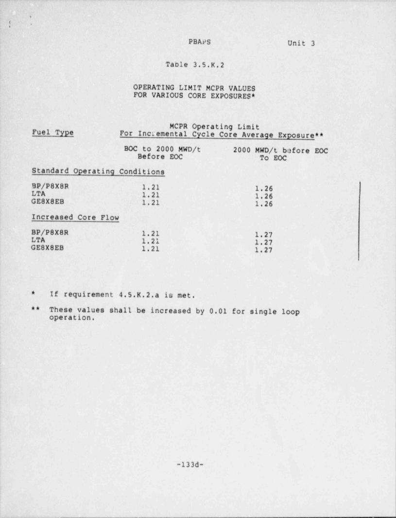
Table 3.5.K.2
OPERATING LIMIT MCPR VALUESFOR VARIOUS CORE EXPOSURES *
MCPR Operating LimitFuel Type For Incremental Cycle Core Average Exposure **
BOC to 2000 MWD /t 2000 MWD /t before EOCBefore EOC To EOC
Standard Operating Conditions
BP/P8X8R 1.21 1.26LTA 1.21 1.26GE8X8EB 1.21 1.26
Increased Core Flow
BP/P8X8R 1.21 1.27LTA 1.21 1.27GE8X8EB 1.21 1.27
* If requirement 4.5.K.2.a is met.
Q* These values shall be increased by 0.01 for single loopoperation.
,
-133d-

_ _ _
l
t -
PBAPS Unit 3
Table 3.5.K.3
OPERATING LIMIT MCPR VALUESFOR VARIOUS CORE fXPOSURES*
MCPR Opera':ing LimitFuel Type For Incremental Cycle Core Average Exposure **
BOC to 2000 MWD /t 2000 MWD /t before EOCBefore EOC To EOC
Standard Operating Conditions
BP/P8X8R 1.26 1.30LTA 1.26 1.30GE8X8EB 1.26 1.30
Increased Core Flow
BP/P8X8R 1.26 1.31LTA 1.26 1.31GE8X8EB 1.26 1.31
* If surveillance requirement of section 4.5.K.2 isnot performed.
** These values shall be increased by 0.01 for single loop operation.
;
.33e-~

m,
25APS,
$ '
3.5 BASES (Cont'd.)
d. . Engineering Safeguards Compartments Cooling and Ventilation
One unit cooler in each pump compartment is capable of providingadequate ventilation flow and cooling. Engineering analyses indicated |that the temperature rise in safeguards compartments without adequateventitation flow or cooling is such that continued operation of thesafeguards equipment or associated auxiliary equipment cannot beassured. Ventilation associated with the High Pressure Service Water-Pumps is also associated with the Er.ergency Service Water pumps, andis specified in Specification 3.9.
I. Average Planar LEGR
This specification assures that the peak cladding temperaturefollowing the postulated design basis loss-of-coolant accident willnot exceed the limit specified in the 10 CFR Part 50, Appendix K.
The peak cladding temperature (PCT) following a postulated loss-of-coolant accident is primarily a function of the average heatgeneration rate of all the rods of a fuel assembly at nny axiallocation and is ont. dependent, secondarily, on the rod-to-rod powerdistribution within an assembly. The peak clad temperature iscalculated assuming a LHGR for the highest powered red which is equalto or lees than the design LHGR. This LEGR times 1.02 is used in theheat-up code along with the exposure dependent steady state gapconductance and rod-to-rod local peaking factors. The TechnicalEp?cification APLHGR is the LHGR of the highest powered rod divided byits local peaking factor. The limiting value for APLHGR is shown in |the applicable figure for each fuel tyr*:,
Only the most limiting and least limiting APLHGR operating limits are 4
shown ln the figures for the multiple lattice fuel types. Compliancewith the lattice-specific, approved APLHGR limits is ensured by usingthe process computer. When an alternate method to the processcomputer is required (i.e. hand calculations and/or alternate computersilaula tion) , the most limiting lattice APLHGR limit for each fuel typeshall be applied to every lattice of that fuel type.The calculational procedure used to establish the APLHGR is based on aloss-of-coolant aceldenc analysis. The analysis was performed usingGeneral Electric (G.E.) calculational models which are consistent withthe rnquirements of Appendix K to 10 CFR Part 50. A completediscussion of each code empicyed in the analysis is presented inReference 4. Input and model changas in the Peach Bottom loss-of-coolant analysis which ate different from the previous analyacsperformed with Reference 4 are described in detail in Reference 8.These changes to the analysis include: (1) consideration of thecounter current flow limiting (CCEL) effect, (2) corrected codeinputs,. and (3) the effect of drilling alternate f'.ow paths in thebundle lower tie plate.
-140-
~- --- - - .-.

_
sa Unit 3.
.a
3.5.K. BASES (Cont'd)
The largest reduction in critical power ratio is then added tothe fuel cladding integrity safety limit MCPR to establish theMCPR-Operating Limit for each fuel type.
IAnalysis of the abnormal operational transients is presented in-Reference 7. Input data and operating conditions used in thisanalysis are shown in Reference 7 and in the Supplemental RelcadLicensing Analysis.
3.5.L. Average Planar LHGR (APLHGR), Local LHGR and Minimum -|Critical Power Ratio (MCPR)
In the event that the calculated value of APLHGR, LHGR or MCPRexceeds its limiting value, a determination is made to ascertainthe cause and initiate corrective action to restore the value towithin prescribed limits. The status of all indicated limitingfuel bundles is reviewed as well as input data associated withthe limiting values such as power distribution, instrumentationdata (Traversing In-Core Probe-TIP, Local Power Range Monitor -LPRM, and reactor heat balance instrumentation), control rodconfiguration, e tc. , ir4 order to determine whether the calculatedvalues are ve '.
In the event tnat the review indicates that the calculated valueexceeding limits is valid, corrective action is immediatelyundertaken to restore the value to within prescribed limits.Following. corrective action, which may involve alterations to thecontrol rod configuration and consequently changes to the corepower distribution, revised instrumentation data, includingchanges to the relative neutron flux distribution, for up to 43in-core locations is obtained and the power distribution, APLHGR,LHGR and MCPR calculated. Corrective action is initiated withinone hour of an indicated value exceeding limits and verificationthat the indicated value is within prescribed limits is obtainedwithin five hours of the initial indication.
In the event that the calculated value of APLHGR, LHGR or MCPRexceeding its limiting value is not valid, i.e., due to anerroneous instrumentation indication, etc., corrective action isinitiated within one hour of an indicated value exceeding limits.Verification that the indicated value is within prescribed limitsis obtained within five hours of the initial indication. Such aninvalid indication would not be a violation of the limitingcondition for operation and therefore would not constitute areportable occurrence.
,
-140b-
%

.
>
. *
Unit 3
3.5.L. BASES (Cont'd)
Operating experience has demonstrated that a calculated value ofAPLHGR, LHGR or MCPR exceeding its limiting value predominatelyoccurs due to this latter cause. This experience coupled withthe extremely unlikely occurrence of concurrent operationexceeding APLHGR, LHGR or MCPR and a Loss-of-Coolant Accident orapplicable Abnormal Operational' Transients demonstrates that thetimes required to initiate corrective action (1 hour) and restorethe calculated value of APLHGR, LHGR or MCPR to within prescribedlimits (5 hours) are adem2 ate.
3.5.M. References
1. "Fuel Densification Effects on General Electric BoilingWater Reactor Fuel", Supplements 6, 7 and 8, NEDM-10735,August 1973.
2. Supplement 1 to Technical Report on Densifications of-General Electric Reactor Fuels, December 14, 1974(Regulatory Staff).
3. Communication: V. A. Moore to I. S. Mitchell, "Modified GEModel for Fuel Densification", Docket 50-321, March 27,1974.
4. General Electric Company Analytical Model for Loss-of-Coolant Analysis in Accordance with 10 CFR 50, Appendix K,NEDE 20566 (Draft), August 1974.
5. General Electric Refil. Reflood Calculation (Supplement toSAFE Code Description) transmitted to the USAEC by letter,G. L. Gyorey to V8ctor Stello, Jr., dated December 20, 1974.
6. DELETED.
7. "General Electric Standard Application for Reactor Fuel",NEDO-240ll-P-A (as amended).
8. Loss-of-Coolant Accident Analysis for Peach Bottom AtomicPower Station Unit 2, NEDO-24081, December 1977, and for {Unit 3, NEDO-24082, December 1977.
9. Loss-of-Coolant Accident Analysis for Peach Bottom AtomicPower Station Unit 2, Supplement 1, NEDE-24081-P, November1986, and for Unit 3, NEDE-24082-P, December 1987.
-140c-
.
-
,
.. .
O
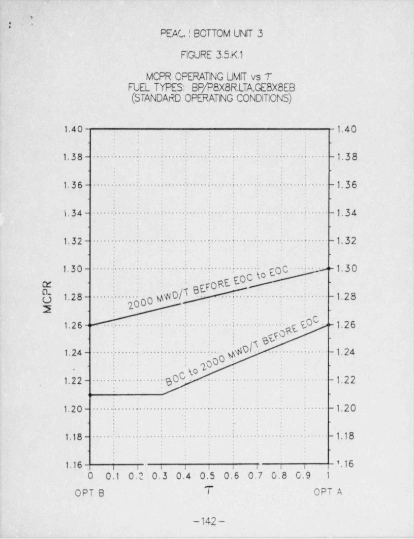
PEAC ! BOTTOM UNfT 3
FlGURE 3.5.K1
.MCPR OPERATING UMIT vs TFUEL TYPES: BP/P8X8R.LTA,GE8X8E8(STANDARD OPERATING CONDITIONS)
1.40 1.40. .
. . . . . .
. . . . . . . .
. . . . . .
. . . .
. . . . . .
1.38- ''-';'':''i:- i- -1.38- '
.
. . . .- . . . . . . . .
. . . . . .
1.36- '-|~'i'i -| l'-| :;
'i - -1.36. . . . .
-. . . .
-.
. . .
} . .-- -1.34'
1.34 - . - - .- .- >
. . . . . .
. . . . . . .
. . . . . ..
1.32 - .. " ~; - : - :i. "- -1.32
. .
. . . . . .
. . . . .
. . . .
. . . . . . . .
1.30- : : i - : i to Eoc ' ; a~ 1. 3 0'
.- oc-
; ""o00 MD|T BEpogE g-
. . ..
cr - - - - -: .
a. - -
'"!"''.~"'"'"!""- -1.28o 1.28-:22 . ..
. . . . .-
. . . . . .
LO ~ 1. 2 61. 2 6 ~ ~. ' .;- ' r-'- - '
E90. . . .
. . . . . . .. .
. - |. - ;- WolT :.. -l.24i.24 - 9. --
2000..
. . .
. -. . . .
. . . o '
C - -1.22.sO1.22 - ~~~~':- - - - -
: :--
.. .. .
...
. . .
. . .
1.20- '':''- . -:-''- -1.20.
. . . ..
. . . . . .-
. . . . . . .
. . . . . . .
- - - -1.181.18 - ''.-'i'++-
. . . .
.-
. . . . . .-
. . .
1.16 | |- | 1 16i i i 3 i i
0 0.1 0.2 0.3 0.4 0.5 0.6 0.7 0.8 0.9 1,
,
OPT B T OPT A
-142 -. . -

.
l1
\..l.. . .
PEACH BOTTOM UNIT 3 l
FIGURE 3.5.K211
MCPR OPERATING UMfT vs TFUEL TYPES: BP/P8X8R,LTA,GE8X8E8
(INCREASED CORE FLOW)
1.40 1.40.
. . .
. . . . . .
. . . . . .
. . .
. . . . .
1.38- ' : '. .
- ~;- -1.38. . .
. . . .
: : .. . . .
. . . . .
1.36-; ; i
;
f i t :- - -1.36. . .
. . . ._
.
. . . .
'
1.34 - ! t- >- - -1.34-
.- . . . -. .
. . . . . .
. . . . . .
. . . . . . .
. . . . .
1.32- .
;. 2. -
;;- -1.32'
. . . . . . .
. . . . .
. .| gg7agt goc to EOCi : i y
.
_3_391.30- . .. . ....
/; 200o A D .
-
-:
'
irx -
,
r.l. .
O 1.28-.
i.;.;;- -1.28'
..
- - -y :_
., ,
. . . . .
gtO 1.261.26-,
.- ~- -
s? yo .
. . . .
$. D'K >g. . .
:-
. . .
. . . .
:- -1.241.24 -,
'.
-
oO .
0 (g %o.
.
.. .
1.22- :- c60;- -1.22- -:--
.. . .
. .
o
.
. ,
1.20- ;- ; - -
-|- -1.20
,
- -.
. . .
. . .
'
;- i- i-1.18 - -| i- - - -1.18.
.
-
.
1.16 ; ; ; 1.16i i i i i i
0 0.1 0.2 0.3 0.4 0.5 0.6 0.7 0.8 0.9 1
OPT 8 7 OPT A
- 142a-

- _ . _ _
..
..
,m .-..
R 14.5 .
r
m.
. .
Least-
a '
y Limitin g - -- - -!------ - - -- - --- -- - ----- --E ? 13.5 - ----- -- - - - -
:
g i 3. o. ' 3 ' 3 is o7 -a3 Lattice .
I # 3 06 12 77Lg 13 6 12.9 1- .C 2.84
2. ou 12.5 - - - - 12. 2 ------ y ----- ' D - -
---- ; -- -;--------- -------------;------------------;-------+
' 12.17C QJ 2.34v O -.-- ti.a7 - - 12. g .
-O ii.6e - Most -
-
Dy 1. a s.
L.n me tin g - -- :- --- - - - - - - - - - - - - - - - - - - - - - - - - - - - - - - - - - - - - - - - - ---.
11.5 - --- -- - - - - - - - - - - - - - - - -
a, c0) O - Lattice - .
11. 2 2 .
0 ._ . .-+-
L 0 *
0'm 10.5- -
-i ->-
b 4C . .
- -
e e . :-
Eo -
i
3 -+- 9.5 - - - - - - ---- -- ---- -----:-- -- -- - - - - '-- ------ ------ --- - -- --- ----- --
.E O- - -
G)
XI -
0 8.5 - --- ---- ----- -- ------ --------- --- ---- -- - - ---- - :-- - --- --------- --- -- -- - -- ----
u~ O .
G) .
C'~J 7. 5 - - - -- - - - - --- -- - - - - - - - - - ---- -- -
G.69' ' ' '
6.5 , , , i i
O 10,000 20,000 30,000 40,000 50,000
Average Planar Exposure (mwd /ST)
MAXIMUM AVERAGE PLANAR LJNEAR HEAT
GENERATION RATE (MAPLHGR) VERSUSAVERAGE PLANAR EXPOSURE
FoH FUEL TYPE BD319A (GE8X8EB)
FIGURE 3.5.tF

,
h
.
* Y
[ 14.5i
.e::r
<
8 Leasta -
Lsm. ling - - -- - - - - - - -- ---- -- - --"g Q 13.5 - --- - - -- -s
* '';' 3is os Lattice'
12.7 6p 12.7 2,93
,LX .78 i 74
a av 12.5 - - ------- ,y.2r--
y-------z, -- .
----~- -- ------ - -- ---- ------- -- -- ----- - --- -- -
2.47 - 12.18C D 12.04w0 -+-- 12.i6 *
-- O "'" ' 11.9 5 Most0-- g 1.s i .
j j, _ .... i,67.......... ... L.imi tin g - --- ----- - - - - - - - - - - - - - - - - - - - - - - - - - - - - - - - - - - - - - - - - - - - - - - - - - - -
o) o i.33 : Lattice.
..
OZ 13.0 5 -
. L O1 mu 10,5 ............. ... . . . ~ . . .......... . ..... .....-... .. ..... ................. ... .. . ......... .
> D .
<f C.
.c..
Dwm O
. . .
3 ,_,_ 9.5 - -------- - - - -- --- ---- -- --: ----- -- -- -----:-------- - ---------- - - -- -I
.E o :~
-
D -
XI~
0 8.5 - - --------- -- ---- ---- - ---- -- - --- --- --- - - - ---------- --- -------- - --- - --u^ O -
D -
.
C -
__-~_; 7,5 - . .. . .. . . ... .. ... .. .. ... .. . ... ... . .. . ..... .. .
.
. :-
s.6e-
6.s2 1
6.S - i , , ,
0 10,000 20,000 30,000 40,000 50,000
Average Planar Exposure (mwd /ST)_
MA>0 MUM AVERAGE PLANAR UNEAR HEAT
GENERATION RATE (MAPLHGR) VERSUSAVERAGE PLANAR EXPOSURE
FOR FUEL TYPE BD321A (GE8X8EB)
FlGURE 35tG
_ - _ - _ _ _ _ _ - . _ _ - _ - _ _ .
. .
&|4: "Q .
'
, .;
i
CERTIFICATE OF SERVICEl
I' hereby certify that copies of the -foregoing Application were served
on . the - following by deposit in the United States Mail, first class postage
; prepaid, 'on -the 7th - day of July,1988.,
Will'am T. Russell, Regional Ad.cinistratori: U.S. Nuclear Regulatory Commission -475 A11endale Road-
King'of Prussia, PA 19406-
T. P. Johnson, Resident Inspector.U.S. Nuclear Regulatory Commission-
*
. Peach Bottom Atomic Power Station| P.O. Box:?99
Delta, PA 17314.
Mr. Thomas Gerusky, Director. Bureau of Radiological ProtectionDepartment of Environmental ResourcesP.O. Box 2063!!arrisburg, ~ PA 17120
---
hI
Eugep J. Bradley /
Attorney for|
Philadelphia Electric Company.
'k
a
,
I
r
- e . . , . . - . . _,-_n., ,.n- . _ , -,-,,-.,_-.,,c~-. .,,,_n,n.e.n,, - , , _ , _ . , , , , , . _ . . _,,,,,..+,,.,-,.,.,e--


![Area between curves - Mathematics Department : … Between Curves We know that if f is a continuous nonnegative function on the interval [a,b], then R b a f (x)dx is the area under](https://static.fdocuments.in/doc/165x107/5ad31cca7f8b9aff738d8533/area-between-curves-mathematics-department-between-curves-we-know-that-if.jpg)

