Instrument Manifold Systems (MS-02-445;rev_1;en-US;Catalog)
30
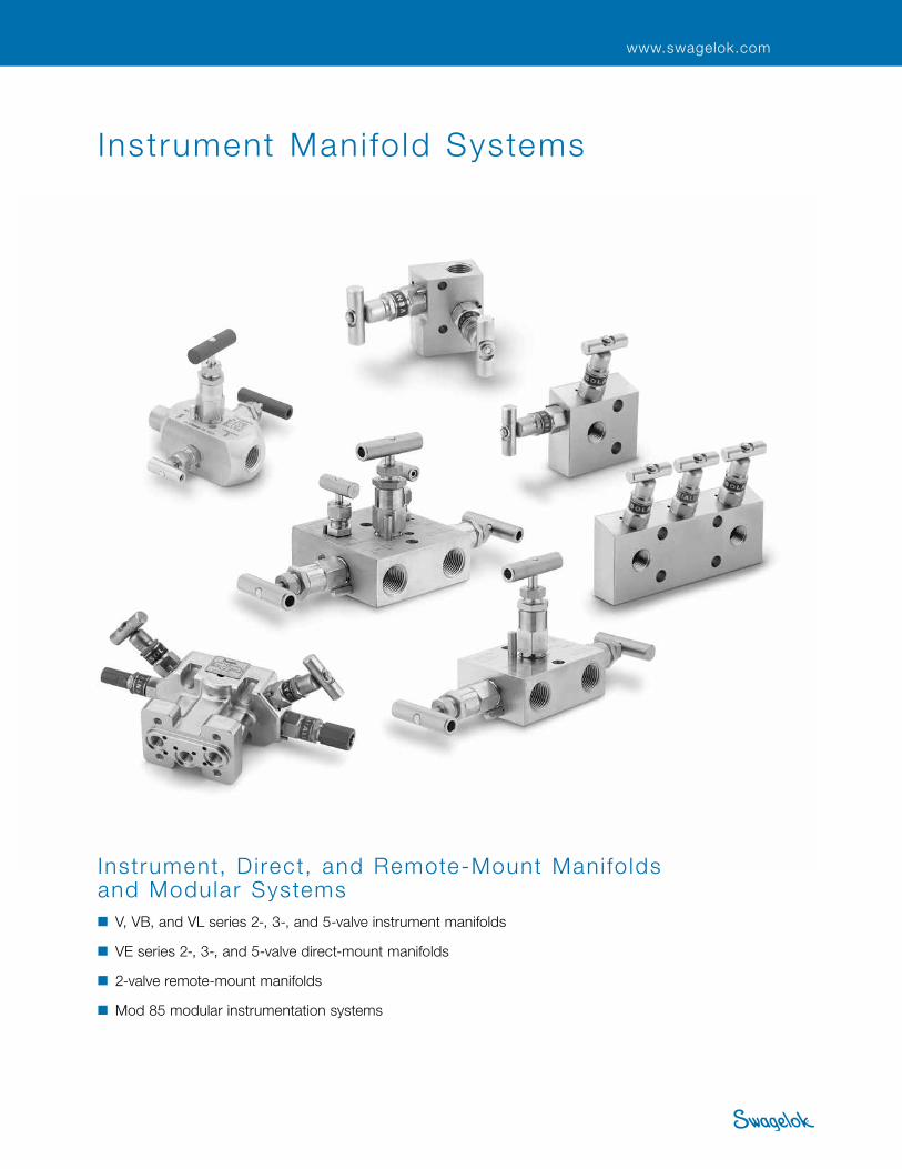
INSTRUMENT MANIFOLD SYSTEMS Instrument Manifold Systems Instrument, Direct, and Remote-Mount Manifolds and Modular Systems ■ V, VB, and VL series 2-, 3-, and 5-valve instrument manifolds ■ VE series 2-, 3-, and 5-valve direct-mount manifolds ■ 2-valve remote-mount manifolds ■ Mod 85 modular instrumentation systems www.swagelok.com
Transcript of Instrument Manifold Systems (MS-02-445;rev_1;en-US;Catalog)
Instrument Manifold Systems 1 INSTRUM
ENT M
ANIFOLD SYSTEM
S
Instrument Mani fo ld Systems
Instrument, D irect, and Remote-Mount Mani fo lds and Modular Systems ■ V, VB, and VL series 2-, 3-, and 5-valve instrument manifolds
■ VE series 2-, 3-, and 5-valve direct-mount manifolds
■ 2-valve remote-mount manifolds
■ Mod 85 modular instrumentation systems
www.swagelok.com

2 ManifoldsIN
STRU
MEN
T M
ANIFO
LD
SYST
EMS
Swagelok offers a variety of 2-, 3-, and 5-valve instrument manifolds. The 2-valve manifolds are designed for static pressure and liquid level applications; the 3- and 5-valve manifolds are designed for differential pressure applications.
These manifolds are available in traditional and compact body designs. Manifold connections include female Swagelok® tube fittings, pipe ends (NPT and ISO 228/1), and flanges (MSS SP-99) in 1/2 and 3/4 in. and 12 mm sizes.
Flange Connections■Flange design meets the requirements of MSS SP-99.
■Standard flange seal is a fluorocarbon FKM O-ring.
■Flange seals and flange bolts are included with manifold.
Bonnet-to-Body Seal■Metal-to-metal seal eliminates the
need for O-ring seals.
Mounting Options■2 1/8 in. (54 mm) port center lines
for direct instrument mounting with flange connections.
■Remote mounting with female Swagelok tube fitting and NPT connections.
Body Design ■All 316 stainless steel.
■One-piece construction provides strength.
■Designed with 4:1 design factor.
Internal Finish■Burr-free threads and internal
surfaces reduce leaks, promoting accurate transmitter readings.
Safety Stop Pin■316 stainless steel pin prevents
detachment of the bonnet from the body due to vibration.
■Design is vibration tested to MIL-STD 167-1, Sections 5.1.2.4.2 through 5.1.2.4.6.
V, VB, and VL Series Instrument Manifolds
Manifold Features . . . . . . . . . . . . . . 2
Valve Features . . . . . . . . . . . . . . . . . 3
Technical Data . . . . . . . . . . . . . . . . . 3
Pressure-Temperature Ratings . . . . 3
V and VL Series 2-Valve Manifolds . . . . . . . . . . . . 4
V Series 3-Valve Manifolds . . . . . . . 8
V and VB Series 5-Valve Manifolds . . . . . . . . . . . . 11
Testing . . . . . . . . . . . . . . . . . . . . . . . 13
Cleaning and Packaging . . . . . . . . . 13
Options . . . . . . . . . . . . . . . . . . . . . . 14
Mounting Kits . . . . . . . . . . . . . . . . . 14
Maintenance Kits . . . . . . . . . . . . . . 14
Direct- and Remote-Mount Manifolds
Features . . . . . . . . . . . . . . . . . . . . . . 15
Materials of Construction . . . . . . . . 15
Pressure-Temperature Ratings . . . . 15
VE Series Direct-Mount Manifolds . . . . . . . . . . . . . . . . . . . 16
2-Valve Remote-Mount Manifolds . . . . . . . . . . . . . . . . . . . 20
Modular Instrumentation Systems
Features . . . . . . . . . . . . . . . . . . . . . . 21
Materials of Construction . . . . . . . . 21
Pressure-Temperature Ratings . . . . 21
Instrument Manifolds . . . . . . . . . . . 22
Purge Blocks . . . . . . . . . . . . . . . . . . 24
Accessories . . . . . . . . . . . . . . . . . . . 25
Instrument Manifold Systems Accessories . . . . . . . . . . . . . . . . . . 26
V, VB, and VL Ser ies Instrument Mani fo lds
Traditional Body
Compact Body
Contents
• A packing adjustment may be required periodically to increase service life and to prevent leakage .
• Valves that have not been cycled for a period of time may have a higher initial actuation torque .
• To increase service life, ensure proper valve performance, and prevent leakage, apply only as much torque as is required to achieve positive shutoff .
Manifold Features

Instrument Manifold Systems 3 INSTRUM
ENT M
ANIFOLD SYSTEM
S
The flow through a Swagelok manifold is controlled by a series of stainless steel needle valves. Each valve has a specific function—to block pressure, to bleed off pressure, or to equalize pressure—depending on its location on the manifold.
The control of all these functions is shared by two needle valve designs—a large-bonnet needle valve for manifold orifices of 0.156 in. (4.0 mm) and a small-bonnet needle valve for manifold orifices of 0.125 in. (3.2 mm).
Large- Bonnet Valve
Technical Data Pressure-Temperature Ratings➀
Packing bolt permits stem packing adjustment.
Hardened stainless steel, nonrotating ball
stem tip provides consistent
shutoff.
Rolled stem threads enhance cycle life.
PTFE packing is below stem threads to isolate threads from system fluid.
Small- Bonnet Valve
Safety back seating seals in the fully open position, providing a secondary stem seal.
➀ Ratings based on optional Grafoil packing. Ratings limited to: ■ –20 to 450°F (–28 to 232°C) with standard fluorocarbon FKM flange seals. ■ 450°F (232°C) with standard PTFE packing. ■ 1000°F (537°C) with Grafoil packing and MSS flange end connection.
On both designs, the stem packing is externally adjustable in the open position. PTFE is the standard packing material; optional Grafoil packing is available for high-temperature applications.
Stainless steel handle features a “divot point” set screw to
resist loosening due to vibration.
Packing nut permits stem packing adjustment.
Rolled stem threads enhance cycle life.
PTFE stem packing seals the system fluid to atmosphere.
Safety back seating seals in the fully open position,
providing a secondary stem seal.
ASME Class 2500
Material Group 2 .2
Material Name 316 SS
Temperature °F (°C)
Working Pressure psig (bar)
–65 (–53) to 100 (37) 200 (93) 250 (121) 300 (148) 350 (176) 400 (204)
6000 (413) 5160 (355) 4910 (338) 4660 (321) 4470 (307) 4280 (294)
450 (232) 500 (260) 550 (287) 600 (315)
4130 (284) 3980 (274) 3870 (266) 3760 (259)
650 (343) 700 (371) 750 (398) 800 (426)
3700 (254) 3600 (248) 3520 (242) 3460 (238)
850 (454) 900 (482) 950 (510) 1000 (537)
3380 (232) 3280 (225) 3220 (221) 3030 (208)
1050 (565) 1100 (593) 1150 (621) 1200 (648)
3000 (206) 2685 (184) 2285 (157) 1715 (118)
Traditional Body Manifolds
Orifice Size (isolation valve)
0.125 in. (3.2 mm) for all 2-valve V series
0.156 in. (4.0 mm) for all others
Weight
2-valve: 2.0 to 3.5 lb (0.9 to 1.6 kg)
3-valve: 3.2 to 6.4 lb (1.5 to 2.9 kg)
5-valve: 6.0 to 8.0 lb (2.7 to 3.6 kg)
Compact Body Manifolds
Orifice Size Vent valves—0.125 in. (3.2 mm)
Isolation valves—0.156 in. (4.0 mm)
Weight
Block and bleed valves— 2.75 to 3.00 lb (1.25 to 1.36 kg)
Double block and bleed valves— 3.10 to 3.35 lb (1.41 to 1.52 kg)
Valve Features

4 ManifoldsIN
STRU
MEN
T M
ANIFO
LD
SYST
EMS
2
68
9
10a
10b
12 13
11
Materials of ConstructionMaterials for pressure-containing wetted parts are in compliance with ASME B31.1.
24
5
11
7
10a
10b
9
1
8
12
Wetted components listed in italics.➀ Isolation valve handles of compact models are
blue enamel coated.
V and VL Series 2-Valve Manifolds
Component Material Grade/
ASTM Specification
1 Handle➀
316 SS/A479
2 Set screw
3 Packing bolt
4 Packing nut
5 Upper gland
6 Jam nut 316 SS/A276
7 Lower gland 316 SS/A240 or A167
8 Packing PTFE/D1710
9 Bonnet 316 SS/A479
10a Stem 316 SS/A276
10b Ball tip 316 SS/A479
11 Body
12 Stop pin 316 SS/A479
Flange seals (not shown) Fluorocarbon FKM
Flange bolts (not shown) B8M CL.2B/A193
Lubricants
Fluorinated base with PTFE and tungsten
disulfide
Hydrocarbon-based
11
2
6
10a
10b
3
1
8
912
2
7
10a
10b
912
854
1
V Series
VL Series
Traditional Body Compact Body

Instrument Manifold Systems 5 INSTRUM
ENT M
ANIFOLD SYSTEM
S
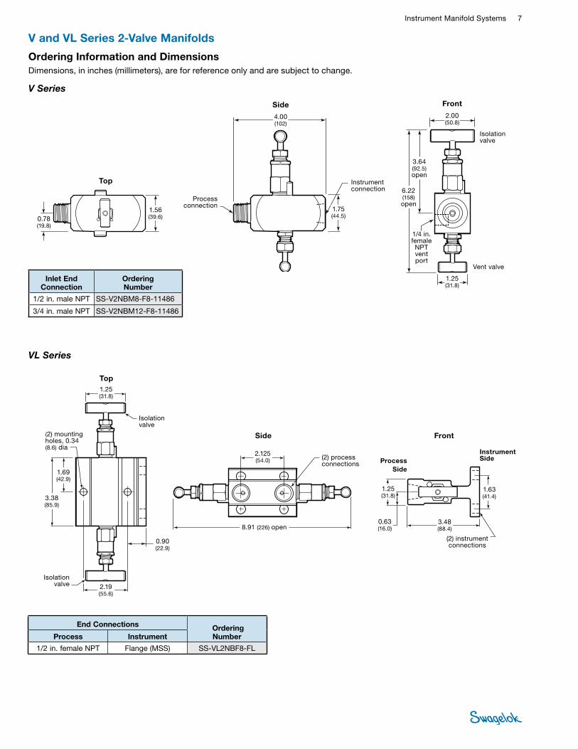
V and VL Series 2-Valve Manifolds
V Series
■Allows for block and bleed (or calibration) of a gauge- or absolute-pressure transmitter or gauge
■Consists of one isolation valve and one vent valve
■End connections—1/2 in. and 12 mm female Swagelok® tube fitting; 1/2 in. female pipe (NPT); flange (MSS)
■Direct instrument mount and remote mount
Isolation
Vent
2-valve V, VE
2-valve remote, 2 valve pressure
3-valve V traditional, VE
3-valve V compact3-valve VL
5-valve V
4-valve DP
purge block double purge block seal pot
4-valve DP 2-valve DP pressure manifold
5-valve VB 5-valve VE
Instrument Side
Process Side
VL Series
■Designed for liquid level applications
■Consists of two isolation valves operating in parallel to shut off either one of the two process lines through the manifold
■No equalizing passage through the manifold
■End connections—1/2 in. female pipe (NPT) to flange
■Direct instrument mount
Isolation
Isolation
Instrument Side
Process Side
2-valve V, VE
2-valve remote, 2 valve pressure
3-valve V traditional, VE
3-valve V compact3-valve VL
5-valve V
4-valve DP
purge block double purge block seal pot
4-valve DP 2-valve DP pressure manifold
5-valve VB 5-valve VE
Isolation
Vent
Instrument Side
Process Side
2-valve V, VE
2-valve remote,
2 valve pressure
3-valve V
traditional, VE
3-valve V
compact
3-valve VL
5-valve V
4-valve DP
purge block
double purge block
seal pot
4-valve DP
2-valve DP
pressure manifold
5-valve VB
5-valve VE

6 ManifoldsIN
STRU
MEN
T M
ANIFO
LD
SYST
EMS
Ordering Information and DimensionsDimensions, in inches (millimeters), are for reference only and are subject to change.
Instrument Manifolds with Flange Connections
Manifolds with Female Swagelok Tube Fitting and Pipe Connections
(2) mounting holes, 0.34
(8.6) dia
Isolation valve
FrontVent
valve
Side
1.63 (41.4)
2.19 (55.6)
A open
Top
C
B ED
F
G open
1.25 (31.8)
Instrument Side
Process Side
Vent connection Instrument
connectionProcess connection
Top
B
Vent valve Front
Side
Isolation valve
1.25 (31.8)
F
C
DE
1.88 (47.8)
Vent connection
Process connection
Instrument connection
A open
G open
0.58 (14.7)
0.62 (15.7)
Instrument Side
Process Side
(2) mounting holes, 0.34 (8.6) dia
End Connections Ordering Number
Dimensions, in. (mm)
Process Instrument Vent A B C D E F G
1/2 in. female Swagelok tube fitting SS-V2BFS8 4.19 (106)
1.89 (48.0)
0.44 (11.2)
2.48 (63.0)
1.31 (33.3)
2.75 (69.9)
3.05 (77.5)
1/2 in. female Swagelok tube fitting Flange (MSS) 1/4 in. female NPT SS-V2BFS8-FL 3.36
(85.3) 1.31 (33.3)
0.90 (22.9)
1.63 (41.4)
1.25 (31.8)
3.46 (87.9)
3.48 (88.4)
12 mm female Swagelok tube fitting SS-V2BFS12MM 4.19 (106)
1.89 (48.0)
0.44 (11.2)
2.48 (63.0)
1.31 (33.3)
2.75 (69.9)
3.05 (77.5)
12 mm female Swagelok tube fitting Flange (MSS) 1/4 in. female NPT SS-V2BFS12MM-FL 3.36
(85.3) 1.31 (33.3)
0.90 (22.9)
1.63 (41.4)
1.25 (31.8)
3.46 (87.9)
3.48 (88.4)
1/2 in. female NPT SS-V2BF8 3.82 (97.0)
1.62 (41.1)
0.31 (7.9)
2.12 (53.8)
1.31 (33.3)
2.50 (63.5)
3.05 (77.5)
1/2 in. female NPT Flange (MSS) 1/4 in. female NPT SS-V2BF8-FL 3.36 (85.3)
1.31 (33.3)
0.90 (22.9)
1.63 (41.4)
1.25 (31.8)
3.48 (88.4)
3.48 (88.4)
V and VL Series 2-Valve Manifolds
V Series
Instrument Manifold Systems 7 INSTRUM
ENT M
ANIFOLD SYSTEM
S
Isolation valve
Side
Instrument Side
Top
Isolation valve
(2) mounting holes, 0.34 (8.6) dia
1.63 (41.4)
1.25 (31.8)
2.19 (55.6)
Process Side
Front
(2) process connections
3.38 (85.9)
1.69 (42.9)
0.90 (22.9)
8.91 (226) open
1.25 (31.8)
0.63 (16.0)
3.48 (88.4)
2.125 (54.0)
(2) instrument connections
End Connections Ordering Number Process Instrument
1/2 in. female NPT Flange (MSS) SS-VL2NBF8-FL
V and VL Series 2-Valve Manifolds
Ordering Information and DimensionsDimensions, in inches (millimeters), are for reference only and are subject to change.
Inlet End Connection
Ordering Number
1/2 in. male NPT SS-V2NBM8-F8-11486
3/4 in. male NPT SS-V2NBM12-F8-11486
0.78 (19.8)
1.56 (39.6)
Top
Side
4.00 (102)
1.75 (44.5)
Process connection
Instrument connection
Front
1.25 (31.8)
3.64 (92.5) open
2.00 (50.8)
6.22 (158) open
1/4 in. female NPT vent port
Isolation valve
Vent valve
V Series
VL Series

8 ManifoldsIN
STRU
MEN
T M
ANIFO
LD
SYST
EMS
V Series 3-Valve Manifolds
2
6
8
9
10a
10b
11
1
3
12
Materials of ConstructionMaterials for pressure-containing wetted parts are in compliance with ASME B31.1.
Wetted components listed in italics.➀ Isolation valve handles of compact models are blue enamel
coated.
Component Material Grade/
ASTM Specification
1 Handle➀
316 SS/A479
2 Set screw
3 Packing bolt
4 Packing nut
5 Upper gland
6 Jam nut 316 SS/A276
7 Lower gland 316 SS/A240 or A167
8 Packing PTFE/D1710
9 Bonnet 316 SS/A479
10a Stem 316 SS/A276
10b Ball tip 316 SS/A479
11 Body
12 Stop pin 316 SS/A479
Flange seals (not shown) Fluorocarbon FKM
Flange bolts (not shown) B8M CL.2B/A193
Lubricants
Fluorinated base with PTFE and tungsten
disulfide
Hydrocarbon-based
2
6
10a
10b
3
1
8
912
2
7
10a 10b9
12
8
5
41
11
Traditional Body
Compact Body

Instrument Manifold Systems 9 INSTRUM
ENT M
ANIFOLD SYSTEM
S
V Series 3-Valve Manifolds
Traditional Body■Designed for mounting on differential
pressure transmitters with 2 1/8 in. (54 mm) center-to-center connections
■Consists of two isolation valves and one equalizing valve
■End connections—1/2 in. and 12 mm female Swagelok tube fitting, 1/2 in. female pipe (NPT), and flange (MSS)
■Instrument flange mount and remote mount
Isolation
Isolation
Equalizing
Isolation
Vent
Isolation
Compact Body■Allows for block and bleed (or
calibration) of a gauge or absolute pressure transmitter or gauge
■Consists of two isolation valves and one vent valve
■End connections—1/2 in. female pipe (NPT)
■Direct instrument mount and remote mount
Instrument Side
Process Side
2-valve V, VE
2-valve remote, 2 valve pressure
3-valve V traditional, VE
3-valve V compact3-valve VL
5-valve V
4-valve DP
purge block double purge block seal pot
4-valve DP 2-valve DP pressure manifold
5-valve VB 5-valve VE
Instrument Side
Process Side
2-valve V, VE
2-valve remote, 2 valve pressure
3-valve V traditional, VE
3-valve V compact3-valve VL
5-valve V
4-valve DP
purge block double purge block seal pot
4-valve DP 2-valve DP pressure manifold
5-valve VB 5-valve VE

10 ManifoldsIN
STRU
MEN
T M
ANIFO
LD
SYST
EMS
V Series 3-Valve Manifolds
Inlet End Connection
Ordering Number
1/2 in. male NPT SS-V3NBM8-F8-11421
3/4 in. male NPT SS-V3NBM12-F8-11421
1.25 (31.8)
3.64 (92.5) open
2.00 (50.8)
6.22 (158) open
Front
1/4 in. female NPT
vent port
Isolation valve
Vent valveIsolation valve
Side4.00 (102)
1.75 (44.5)
Process connection
Instrument connection
Top
0.78 (19.8)
1.56 (39.6)
4.33 (110)
(2) mounting holes, 0.34 (8.6) dia
Top
Side2.00 (50.8)
E
C
Isolation valve
Process Side
Instrument Side
Isolation valve
Equalizing valve Front
1.63 (41.4)H
(2) process connections
➀ SS-V3NBF8: 1.75 (44.5).
(2) instrument connections
0.59 (15.0)
1.60 (42.9)➀
K
G open
2.125 (54.0)
A open
D
F
Ordering Information and DimensionsDimensions, in inches (millimeters), are for reference only and are subject to change.
End Connections Ordering Number
Dimensions, in. (mm)
Process Instrument A C D E F G H K
1/2 in. female NPT SS-V3NBF8 9.03 (229) 0.31 (7.9) 3.50
(88.9) 1.31 (33.3)
2.50 (63.5)
4.08 (104)
0.66 (16.8)
1.88 (47.8)
1/2 in. female NPT Flange (MSS) SS-V3NBF8-FL
8.91 (226)
0.90 (22.9)
3.38 (85.9)
1.25 (31.8)
3.48 (88.4)
4.51 (115)
0.63 (16.0)
2.19 (55.6)
1/2 in. female Swagelok tube fitting SS-V3NBFS8 0.46 (11.7)
1.31 (33.3)
3.04 (77.2)
4.08 (104)
0.66 (16.8)
1.88 (47.8)
1/2 in. female Swagelok tube fitting Flange (MSS) SS-V3NBFS8-FL 0.90
(22.9) 1.25 (31.8)
3.48 (88.4)
4.51 (115)
0.63 (16.0)
2.19 (55.6)
12 mm female Swagelok tube fitting SS-V3NBFS12MM 0.46 (11.7)
1.31 (33.3)
3.04 (77.2)
4.08 (104)
0.66 (16.8)
1.88 (47.8)
12 mm female Swagelok tube fitting Flange (MSS) SS-V3NBFS12MM-FL
0.90 (22.9)
1.25 (31.8)
3.48 (88.4)
4.51 (115)
0.63 (16.0)
2.19 (55.6)
Flange (MSS) SS-V3NBFL 2.40 (61.0)
4.07 (103)
4.55 (116)
1.20 (30.5)
1.88 (47.8)
Manifold with Female Swagelok Tube Fitting-To-Flange Connections

Instrument Manifold Systems 11 INSTRUM
ENT M
ANIFOLD SYSTEM
S
2
45
86
7
10b
8
1
3
9
10a
11
9
10b10a
12
2
1
12
V series body shown.
■1/2 in. and 12 mm female Swagelok tube fittings, 1/2 in. female pipe (NPT), and flange (MSS) end connections
■Instrument flange mount and remote mount
Materials of ConstructionMaterials for pressure-containing wetted parts are in compliance with ASME B31.1.
Wetted components listed in italics.
Component Material Grade/
ASTM Specification
1 Handle
316 SS/A479
2 Set screw
3 Packing bolt
4 Packing nut
5 Upper gland
6 Jam nut 316 SS/A276
7 Lower gland 316 SS/A240 or A167
8 Packing PTFE/D1710
9 Bonnet 316 SS/A479
10a Stem 316 SS/A276
10b Ball tip 316 SS/A479
11 Body
12 Stop pin 316 SS/A479
Flange seals (not shown) Fluorocarbon FKM
Flange bolts (not shown) B8M CL.2B/A193
Lubricants Fluorinated base with PTFE and
tungsten disulfide
Hydrocarbon-based
V Series VB Series
■Designed for mounting on differential pressure transmitters where a double-equalize function is required
■Consists of two isolation valves, two equalizing valves, and one vent valve
■Designed for mounting on differential pressure transmitters where a double-bleed function is required.
■Consists of two isolation valves, two vent valves, and one equalizing valve
Equalizing
VentVent
Isolation
Equalizing Vent
IsolationIsolation
Isolation
Instrument Side
Process Side
2-valve V, VE
2-valve remote, 2 valve pressure
3-valve V traditional, VE
3-valve V compact3-valve VL
5-valve V
4-valve DP
purge block double purge block seal pot
4-valve DP 2-valve DP pressure manifold
5-valve VB 5-valve VE
Instrument Side
Process Side
2-valve V, VE
2-valve remote, 2 valve pressure
3-valve V traditional, VE
3-valve V compact3-valve VL
5-valve V
4-valve DP
purge block double purge block seal pot
4-valve DP 2-valve DP pressure manifold
5-valve VB 5-valve VE
Equalizing
V and VB Series 5-Valve Manifolds

12 ManifoldsIN
STRU
MEN
T M
ANIFO
LD
SYST
EMS
(2) mounting holes, 0.34 (8.6) dia
Top
Side
2.00 (50.8) E
1.13 (28.7)
C
Isolation valve
Isolation valve
Equalizing valve
Front
1.63 (41.4)
F2.125 (54.0)
1.25 (31.8)Equalizing valve
Vent valve
(1) vent connection
(2) process connections
G open
H
Direct Instrument Mount Manifolds with Flange Connections
(2) instrument connections
Manifolds with Female Swagelok Tube Fitting and Pipe Connections
8.91 (226) open
3.38 (85.9)
Process Side
Instrument Side
Top
Side Front
1.25 (31.8)
E
F
H
(2) mounting holes, 0.34 (8.6) dia
1.13 (28.7)
2.00 (50.8)
Isolation valveIsolation valve
Equalizing valve Equalizing valveVent valve
Vent connection
(2) process connections
G
C
(2) instrument connections
0.59 (15.0)
8.91 (226) open
3.38 (85.9)
2.125 (54.0)
Process Side
Instrument Side
V and VB Series 5-Valve Manifolds
Ordering Information and DimensionsDimensions, in inches (millimeters), are for reference only and are subject to change.
End Connections Ordering Number
Dimensions, in. (mm)
Process Instrument Vent C E F G H
1/2 in. female Swagelok tube fitting
1/4 in. female NPT
SS-V5NBFS8 1.28 (32.5)
1.31 (33.3)
3.55 (90.2)
3.05 (77.5)
0.63 (16.0)
1/2 in. female Swagelok tube fitting Flange (MSS) SS-V5NBFS8-FL 2.88
(73.2) 1.49 (37.8)
4.43 (114)
3.64 (92.5)
0.75 (19.1)
12 mm female Swagelok tube fitting SS-V5NBFS12MM 1.28 (32.5)
1.31 (33.3)
3.55 (90.2)
3.05 (77.5)
0.63 (16.0)
12 mm female Swagelok tube fitting Flange (MSS) SS-V5NBFS12MM-FL 2.88
(73.2) 1.49 (37.8)
4.43 (114)
3.64 (92.5)
0.75 (19.1)
1/2 in. female NPT SS-V5NBF8 1.42 (36.0)
1.31 (33.3)
3.62 (91.9)
3.05 (77.5)
0.63 (16.0)
1/2 in. female NPT Flange (MSS) SS-V5NBF8-FL 2.88 (73.2)
1.49 (37.8)
4.47 (114) 3.66
(93.0)
0.75 (19.1)
Flange (MSS) 1/8 in. female NPT SS-V5NBFL 2.98 (75.7)
1.50 (38.1)
5.00 (127) —
V Series

Instrument Manifold Systems 13 INSTRUM
ENT M
ANIFOLD SYSTEM
S
V and VB Series 5-Valve Manifolds
Manifold With Female Swagelok Tube Fitting-To-Flange Connections
Ordering Information and DimensionsDimensions, in inches (millimeters), are for reference only and are subject to change.
Top Side
Front
1.25 (31.8)
E
F
H
(2) mounting holes, 0.34 (8.6) dia
1.69 (42.9)
2.00 (50.8)
Isolation valve
Isolation valve
Equalizing valve
Vent valve
Vent connection
(2) process connections
G open
C
K
1.63 (41.4)
Vent valve
3.38 (85.9)
0.59 (15.0)
8.91 (226) open
2.125 (54.0)
Process side
Instrument side
End Connections Ordering Number
Dimensions, in. (mm)
Process Instrument Vent C E F G H K
1/2 in. female NPT
1/8 in. female NPT
SS-VB5NBF8 1.22 (31.0)
1.31 (33.3)
3.62 (91.9)
4.10 (104)
0.61 (15.5)
1.88 (47.8)
1/2 in. female NPT Flange (MSS) SS-VB5NBF8-FL 0.94 (23.9)
1.49 (37.8)
4.47 (114)
4.76 (121)
0.75 (19.1)
1.35 (34.3)
1/2 in. female Swagelok tube fitting SS-VB5NBFS8 1.22
(31.0) 1.31 (33.3)
3.65 (92.7)
4.10 (104)
0.61 (15.5)
1.88 (47.8)
1/2 in. female Swagelok tube fitting Flange (MSS) SS-VB5NBFS8-FL 0.94
(23.9) 1.49 (37.8)
4.43 (113)
4.76 (121)
0.75 (19.1)
1.35 (34.3)
VB Series
TestingEvery Swagelok V, VB, and VL series instrument manifold is factory tested with nitrogen at 1000 psig (69 bar). Seats have a maximum allowable leak rate of 0.1 std cm3/min.
Shell testing is performed with a liquid leak detector to a require ment of no detectable leakage.
Cleaning and PackagingEvery Swagelok V, VB, and VL series instrument manifold is cleaned and packaged in accordance with Swagelok Standard Cleaning and Packaging (SC-10) catalog, MS-06-62.

14 ManifoldsIN
STRU
MEN
T M
ANIFO
LD
SYST
EMS
MSS Flange Fasteners■Optional long studs or short bolts are available for special
flange mounting applications. See table below for flange fastener length comparison.
■All fasteners are stainless steel with 7/16-20 threads.
■Optional fasteners are available for all V, VB, and VL series manifolds with MSS flanges.
To order a manifold with optional flange fasteners, add a fastener designator to the manifold ordering number.
Example: SS-V3NBF8-FL-LGB
Mounting Hole Center Line■Elongated mounting holes on the instrument flange allow
for center line installations between 2 1/8 and 2 1/4 in. (54.0 and 57.2 mm).
■Available on 3- and 5-valve V and VB series manifolds with MSS flanges.
■Pressure rating is 3600 psig at 100°F (248 bar at 37°C) and 2480 psig at 450°F (170 bar at 232°C).
To order, add -EH to the manifold ordering number.
Example: SS-V5NBF8-FL-EH
Hydrostatic Testing Hydrostatic testing is available as an option.
To order, add -W20 to the manifold ordering number.
Example: SS-V2BF8-W20
MSS Flange Fasteners
Length in. (mm)
Hex Size in.
Fastener Designator
Standard hex head bolt 1.0 (25.4) 5/8 —
Long stud with hex nut 2.6 (66.0) 11/16 -LGB
Short hex head bolt 0.875 (22.2) 5/8 -SHB
Flange Seal and Bolt Kits ■Kit contains flange seals,
flange bolts, lubricant, and instructions.
■Select a kit ordering number from the tables below based on the manifold series, flange style, and seal material.
Mounting Bracket KitKit contains stainless steel bracket, U-bolts, cap screws, nuts, lock washers, spacer, and instructions. Kit does not fit 3-valve manifolds with flange-to-flange end connections.
Ordering number: SS-MB-VBK
Steam-Trace Block KitsKit contains plated steel trace block with two 1/4 in. female NPT ports, cap screws, nuts, lock washers, block retainer plate, heat transfer gasket, and instructions.
Mounting Kits
Maintenance Kits
V, VB, and VL Series with MSS Flanges
High-Temperature Packing■Grafoil valve packing material for high-temperature service.
See Pressure-Temperature Ratings, page 3.
■Includes Grafoil flange seals on MSS flanges.
To order a manifold with optional Grafoil packing, add -G to the manifold ordering number.
Example: SS-V3NBF8-FL-G
Flange Seal Materials ■MSS flange seals are available in Grafoil, virgin PTFE, and
reinforced PTFE for system compatibility.
■Temperature ratings are included in the table below.
To order a manifold with an optional MSS flange seal material, add a material designator to the manifold ordering number.
Example: SS-V3NBF8-FL-T
Options
MSS Flange Seal
Material Material
Designator Lubricant/
Sealant
Temperature Rating °F (°C)
Packing Material
Fluorocarbon FKM — Silicone
base –20 to 450 (–28 to 232) PTFE
Grafoil -G Fluorinated base
–65 to 1000 (–53 to 537) Grafoil
Virgin PTFE -T Silicone
base –65 to 250 (–53 to 121)
PTFE
Reinforced PTFE -TRL PTFE
Flange Seal Material
Kit Ordering Number
2-Valve 3- and 5-Valve
Fluorocarbon FKM SS-MK-V2V SS-MK-V3V
Grafoil SS-MK-V2G SS-MK-V3G
Virgin PTFE SS-MK-V2T SS-MK-V3T
Reinforced PTFE SS-MK-V2R SS-MK-V3R
Manifold StylesKit Ordering
Number
3-valve, flange S-MB-M3SK
3-valve, pipe-to-pipe
S-MB-M5SK3-valve, tube-to-tube
5-valve, all styles

Instrument Manifold Systems 15 INSTRUM
ENT M
ANIFOLD SYSTEM
S
Features■Compact design
■Stainless steel stop pin
■Color-coded valve label rings
Pressure-Temperature Ratings
Orifice Size
in. (mm)
PTFE Seals Graphite Seals
Temperature °F (°C)
Working Pressure psig (bar)
Temperature °F (°C)
Working Pressure psig (bar)
0.197 (5)–58 (–50) to 200 (93) 6000 (413) –58 (–50) to 200 (93) 6000 (413)
201 (94) to 400 (204) 4000 (275) 201 (94) to 850 (454) 3000 (206)
■Graphite packing and seals available
■Material traceability available; contact your authorized Swagelok sales and service representative.
Valve
Stem threads are cold rolled for high strength and smooth operation
Stainless steel handle with square drive stem and lock nut
to ensure positive actuation
Stem threads above packing protected from system media
Shroud protects stem threads against ingress of dirt and dust
Choice of packing and bonnet seal materialsSafety back-seating
needle seals in fully open position
Nonrotating, hardened needle for positive shutoff
Two-piece knuckle joint enables nonrotating needle;
joint is above packing, protected from system media
Direct- and Remote-Mount Mani fo lds
Materials of Construction
Component Grade/ASTM Specification
Body, bonnets 316/316L SS/A479
Needles S17400 SS/A564 Condition H1150D
Packing, bonnet seals PTFE or graphite
Lubricant Molybdenum disulfide in
hydrocarbon carrier
Gland lock nuts 300 series powdered metal SS
All other components 316 SS
Wetted components listed in italics.
• A packing adjustment may be required periodically to increase service life and to prevent leakage .
• Valves that have not been cycled for a period of time may have a higher initial actuation torque .
• To increase service life, ensure proper valve performance, and prevent leakage, apply only as much torque as is required to achieve positive shutoff .
VE and MSBG Series Manifolds

16 ManifoldsIN
STRU
MEN
T M
ANIFO
LD
SYST
EMS
1/4 in. female NPT or ISO 228/1
vent port
VE Series Direct-Mount Manifolds
DimensionsDimensions, in inches (millimeters), are for reference only and are subject to change.
1.75 (44.5)
2 mounting holes, M8, 10 mm deep
5.63 (143)valve fully open
1.44 (36.5)
1.18 (30.0)
0.47 (12.0)
3.15 (80.0)
2.16 (54.8)
3.00 (76.2)
Isolation valve
Vent valve
0.78 (19.8)
1.25 (31.8)
2.05 (52.0)
2-Valve Manifold■Direct mounting to gauges, pressure
switches, or absolute pressure transmitters
■Vent port
■female NPT with NPT process connection
■female ISO 228/1 with ISO 228/1 process connection
Isolation
Vent
FeaturesVE series manifolds mount directly to pressure and differential pressure transmitters
■MSS SP-99 and DIN EN 61518 flange connections are available
■High-tensile steel instrument bolt and PTFE seal kit are included with each manifold
■Mounting bracket kits are available
2.56 (65.0)valve fully
open
2-valve V, VE
2-valve remote, 2 valve pressure
3-valve V traditional, VE
3-valve V compact3-valve VL
5-valve V
4-valve DP
purge block double purge block seal pot
4-valve DP 2-valve DP pressure manifold
5-valve VB 5-valve VE
Instrument Side
Process Side

Instrument Manifold Systems 17 INSTRUM
ENT M
ANIFOLD SYSTEM
S
3-Valve Manifold■Direct mounting to instrument on
2.12 in. (54.0 mm) centers
2 mounting
holes, M8, 10 mm deep
5.63 (143)valve fully open
2.00 (50.8)
1.75 (44.5)
2.00 (50.8)
1.44 (36.5)
1.18 (30.0)
5.28 (134)
1.25 (31.8)
3.00 (76.2)
2.12 (54.0)instrument
connections
4.00 (102) process connections
Isolation valve
Isolation valve
Equalizing valve
DimensionsDimensions, in inches (millimeters), are for reference only and are subject to change.
VE Series Direct-Mount Manifolds
Isolation
Isolation
Equalizing
2.56 (65.0)valve fully
open
Instrument Side
Process Side
2-valve V, VE
2-valve remote, 2 valve pressure
3-valve V traditional, VE
3-valve V compact3-valve VL
5-valve V
4-valve DP
purge block double purge block seal pot
4-valve DP 2-valve DP pressure manifold
5-valve VB 5-valve VE

18 ManifoldsIN
STRU
MEN
T M
ANIFO
LD
SYST
EMS
5-Valve Manifold■Direct mounting to instrument on
2.12 in. (54.0 mm) centers
■Two vent ports
■female NPT with NPT process connections
■female ISO 228/1 with ISO 228/1 process connections
DimensionsDimensions, in inches (millimeters), are for reference only and are subject to change.
VE Series Direct-Mount Manifolds
2 mounting holes M8, 10 mm deep
5.63 (143) valve fully open
2.00 (50.8)
2.00 (50.8)
1.44 (36.5)
1.18 (30.0)
5.48 (140)
6.46 (164)
0.78 (19.8)
1.25 (31.8)
2.05 (52.0)
3.00 (76.2)
2.12 (54.0) instrument
connections
4.00 (102) process connections
2.56 (65.0) valve fully
open1.75 (44.5)
Vent valveVent valve
Isolation valve
Isolation valve
Equalizing valve
11.8 (301) valves fully
open
Two 1/4 in. female NPT or ISO 228/1 vent ports
Vent
Vent
Isolation
Isolation
Equalizing Instrument Side
Process Side
2-valve V, VE
2-valve remote, 2 valve pressure
3-valve V traditional, VE
3-valve V compact3-valve VL
5-valve V
4-valve DP
purge block double purge block seal pot
4-valve DP 2-valve DP pressure manifold
5-valve VB 5-valve VE
Instrument Manifold Systems 19 INSTRUM
ENT M
ANIFOLD SYSTEM
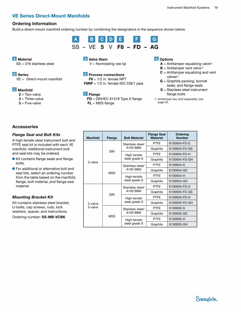
SMounting Bracket KitKit contains stainless steel bracket, U-bolts, cap screws, nuts, lock washers, spacer, and instructions.
Ordering number: SS-MB-VCBK
Accessories
Flange Seal and Bolt KitsA high-tensile steel instrument bolt and PTFE seal kit is included with each VE manifold. Additional instrument bolt and seal kits may be ordered.
■Kit contains flange seals and flange bolts.
■For additional or alternative bolt and seal kits, select an ordering number from the table based on the manifold, flange, bolt material, and flange seal material.
Manifold Flange Bolt MaterialFlange Seal
MaterialOrdering Number
2-valve
DIN
Stainless steel/A193 B8M
PTFE K100934-FD-S
Graphite K100934-FD-GS
High-tensile steel grade S
PTFE K100934-FD-H
Graphite K100934-FD-GH
MSS
Stainless steel/A193 B8M
PTFE K100934-S
Graphite K100934-GS
High-tensile steel grade S
PTFE K100934-H
Graphite K100934-GH
3-valve, 5-valve
DIN
Stainless steel/A193 B8M
PTFE K100935-FD-S
Graphite K100935-FD-GS
High-tensile steel grade S
PTFE K100935-FD-H
Graphite K100935-FD-GH
MSS
Stainless steel/A193 B8M
PTFE K100935-S
Graphite K100935-GS
High-tensile steel grade S
PTFE K100935-H
Graphite K100935-GH
VE Series Direct-Mount Manifolds
SS – VE 5 V F8 – FD – AG
Ordering InformationBuild a direct-mount manifold ordering number by combining the designators in the sequence shown below.
B DA C E GF
A Material SS = 316 stainless steel
D Valve Stem V = Nonrotating vee tip
G Options A = Antitamper equalizing valve➀ B = Antitamper vent valve➀ C = Antitamper equalizing and vent
valves➀ G = Graphite packing, bonnet
seals, and flange seals S = Stainless steel instrument
flange bolts➀ Antitamper key sold separately; see
page 25.
B Series VE = Direct-mount manifold
E Process connections F8 = 1/2 in. female NPT F8RP = 1/2 in. female ISO 228/1 pipe
C Manifold 2 = Two-valve 3 = Three-valve 5 = Five-valve
F Flange FD = DIN/IEC 61518 Type A flange FL = MSS flange

20 ManifoldsIN
STRU
MEN
T M
ANIFO
LD
SYST
EMS
2-Valve Remote-Mount Manifold
Features■Angled vent valve for panel mounting
■Color-coded valve label rings for easy valve identification
■Available graphite packing and seals for high-temperature service
DimensionsDimensions, in inches (millimeters), are for reference only and are subject to change.
1.25 (31.8)
4.00 (102)open
3.25 (82.6)open 1.90
(48.3)open
2 clearance holes for 1/4 in. dia bolts
2.05 (52.1)
1.03 (26.2)
2.50 (63.5)
1/4 in. female NPT vent
0.75 (19.0)
0.84 (21.3)
1.41 (35.8)
M S B G 4 N A T
Ordering InformationBuild a remote-mount manifold ordering number by combining the designators in the sequence shown below.
BA C
A Material S = Stainless steel C = Carbon steel
B End Connections 2N = 1/4 in. female NPT 4N = 1/2 in. female NPT
C Packing, Bonnet Seal Material A = PTFE C = Graphite
TestingEvery direct- and remote-mount manifold is factory tested hydrostatically. A shell test is performed at 1.5 times maximum rated working pressure, and a seat test is performed at 1.1 times maximum rated working pressure, in accordance with BS EN 12266-1 (formerly BS 6755 part 1).
Instrument Side
Process Side
2-valve V, VE
2-valve remote, 2 valve pressure
3-valve V traditional, VE
3-valve V compact3-valve VL
5-valve V
4-valve DP
purge block double purge block seal pot
4-valve DP 2-valve DP pressure manifold
5-valve VB 5-valve VE
Vent
Isolation

Instrument Manifold Systems 21 INSTRUM
ENT M
ANIFOLD SYSTEM
S
Stem threads are cold rolled for high strength and smooth operation
Stainless steel handle with square drive stem and lock nut
to ensure positive actuation
Stem threads above packing protected from system media
Shroud protects stem threads against ingress of dirt and dust
Choice of packing and bonnet seal materialsSafety back-seating
needle seals in fully open position
Nonrotating, hardened needle for positive shutoff
Two-piece knuckle joint enables nonrotating needle;
joint is above packing, protected from system media
Features■A standard series of 2- and 4- valve manifolds for pressure
and differential pressure measurement
■Instrument monoflanges provide isolation and vent functions for local instrument or indicator mounting
■Metal-to-metal seals and parallel threads in accordance with BS 2779 (ISO 228/1)
■Allows pre-assembly that can reduce field installation time and cost
■Hydrostatic test certificates complete with full chemical and physical material certifications available
Materials of Construction
Component Grade/ASTM Specification
Body CF8M/ASTM A351
Bonnets 316/316L SS/A479
Needles S17400 SS/A564 Condition H1150D
Packing, bonnet seals PTFE
Lubricant Molybdenum disulfide in
hydrocarbon carrier
Gland lock nuts 300 series powdered metal SS
All other components 316 SS
Wetted components listed in italics.
Modular 85 System
• A packing adjustment may be required periodically to increase service life and to prevent leakage .
• Valves that have not been cycled for a period of time may have a higher initial actuation torque .
• To increase service life, ensure proper valve performance, and prevent leakage, apply only as much torque as is required to achieve positive shutoff .
Pressure-Temperature Ratings
Orifice Size
in. (mm)
PTFE Seals Graphite Seals
Temperature °F (°C)
Working Pressure psig (bar)
Temperature °F (°C)
Working Pressure psig (bar)
0.197 (5)–58 (–50) to 200 (93) 6000 (413) –58 (–50) to 200 (93) 6000 (413)
201 (94) to 400 (204) 4000 (275) 201 (94) to 850 (454) 3000 (206)

22 ManifoldsIN
STRU
MEN
T M
ANIFO
LD
SYST
EMS
Four-Valve Differential-Pressure Manifold■For applications where cross-contamination of process
fluids is not permitted
■Two isolation and two vent valves
■Direct mounting to instrument on 2 1/8 in. (54 mm) centers and mounting plate
■Installation allows vent port to be higher than the process ports for liquid service, and below for gas service; manifolds marked for liquid and gas service
■Bolt and seal kit K7179 included with each manifold purchased
Ordering Information
Description Ordering Number
G1/4 M5705S0001
G1/4 with 3/8 in. Swagelok tube fittings installed M5705S0003
G1/4 with 10 mm Swagelok tube fittings installed
(as shown)M5705S0005
■Bar handle on isolation valves
■Equalizing and vent valves fitted with antitamper feature
■All valves color coded and labeled
■Process and vent connection: 1/4 in. ISO parallel thread (G1/4) with locking pin feature
■Supplied complete with locking pins, gaskets, and four M8 mounting plate screws
■Factory installed and tested Swagelok® tube fittings with locking pin and gasket available
■Instrument mounting face in accordance with DIN 19213
Four-Valve Differential-Pressure Manifold■Two isolation, one equalizing, and one vent valves
■Direct mounting to instrument on 2 1/8 in. (54 mm) centers and mounting plate
■Installation allows vent port to be higher than the process ports for liquid service, and below for gas service; manifolds marked for liquid and gas service
■Bolt and seal kit K7179 included with each manifold purchased
Ordering Information
Description Ordering Number
G1/4 (as shown) M5156S0001
G1/4 with 3/8 in. Swagelok tube fittings installed M5156S0003
G1/4 with 10 mm Swagelok tube fittings installed M5156S0005
Instrument Side
Process Side
2-valve V, VE
2-valve remote, 2 valve pressure
3-valve V traditional, VE
3-valve V compact3-valve VL
5-valve V
4-valve DP
purge block double purge block seal pot
4-valve DP 2-valve DP pressure manifold
5-valve VB 5-valve VE
Instrument Side
Process Side
2-valve V, VE
2-valve remote, 2 valve pressure
3-valve V traditional, VE
3-valve V compact3-valve VL
5-valve V
4-valve DP
purge block double purge block seal pot
4-valve DP 2-valve DP pressure manifold
5-valve VB 5-valve VE
Isolation
Isolation
Vent
Equalizing
Isolation
Isolation
Vent
Vent
Instrument Manifolds
Features

Instrument Manifold Systems 23 INSTRUM
ENT M
ANIFOLD SYSTEM
S
Instrument Manifolds
Two-Valve Pressure Manifold■For absolute and gauge pressure transmitters
■One isolation and one vent valve
■Bolt and seal kit K7180 included with each manifold purchased
Ordering Information
Description Ordering Number
G1/4 (as shown) M6006S0001
G1/4 with 3/8 in. Swagelok tube fittings installed M6006S0003
G1/4 with 10 mm Swagelok tube fittings installed M6006S0005
Two-Valve Differential Pressure Manifold■For low-pressure applications and level measure on
atmospheric tanks with differential pressure cell
■One isolation and one vent valve
■Direct mounting to instrument on 2 1/8 in. (54 mm) centers, and mounting plate
■Bolt and seal kit K7179 included with each manifold purchased
Ordering Information
Description Ordering Number
G1/4 (as shown) M5706S0001
G1/4 with 3/8 in. Swagelok tube fittings installed M5706S0003
G1/4 with 10 mm Swagelok tube fittings installed M5706S0005
Pressure Manifold■For direct connecting to pressure transmitters or pressure
gauges and mounting plates
■One isolation and one vent valve
■Integral gauge adapter, 1/2 in. NPT for 360° positioning, 1/2 in. ISO parallel thread (G1/2) option
Ordering Information
Description Ordering NumberG1/4 (process),
1/2 in. positionablemale NPT (instrument)
M5713S1001
G1/4 (process), 1/2 in. positionable
female NPT (instrument)M5713S2001
G1/4 with 3/8 in. Swagelok tube fitting installed (1/2 in. male NPT)
(as shown)
M5713S1003
G1/4 with 10 mm Swagelok tube fitting installed (1/2 in. female NPT)
M5713S2005
Instrument Side
Process Side
2-valve V, VE
2-valve remote, 2 valve pressure
3-valve V traditional, VE
3-valve V compact3-valve VL
5-valve V
4-valve DP
purge block double purge block seal pot
4-valve DP 2-valve DP pressure manifold
5-valve VB 5-valve VE
Instrument Side
Process Side
2-valve V, VE
2-valve remote, 2 valve pressure
3-valve V traditional, VE
3-valve V compact3-valve VL
5-valve V
4-valve DP
purge block double purge block seal pot
4-valve DP 2-valve DP pressure manifold
5-valve VB 5-valve VE
Instrument Side
Process Side
2-valve V, VE
2-valve remote, 2 valve pressure
3-valve V traditional, VE
3-valve V compact3-valve VL
5-valve V
4-valve DP
purge block double purge block seal pot
4-valve DP 2-valve DP pressure manifold
5-valve VB 5-valve VE
Isolation
Isolation
Isolation
Vent
Vent
Vent

24 ManifoldsIN
STRU
MEN
T M
ANIFO
LD
SYST
EMS
■Complete with one vent valve, one integral filter, one or two soft-seated check valves
■Suitable for connecting to instrument impulse lines on 2 1/8 in. (54 mm) centers
■Brackets and fixing bolts supplied for mounting to 2 in. pipe stand
■Vent valve fitted with antitamper feature
■Integral filter screen: 750 µm
■Check valve spring: nickel alloy
■Process connections: 10 mm or 3/8 in. Swagelok tube fitting
■Purge supply and vent connection: 1/4 in. ISO parallel thread (G1/4) or 1/4 in. NPT option with locking pin and gasket
■Pressure-temperature ratings: 6000 psig (413 bar) at 100°F (37°C) 4000 psig (275 bar) at 400°F (204°C)
■Factory installed and tested Swagelok tube fittings with locking pin and gasket
Self-Venting Double Purge Block■Suitable for differential pressure measurement and for
connecting to instrument impulse lines on 2 1/8 in. (54 mm) centers
Ordering Information
Description Ordering NumberG1/4 with 3/8 in. Swagelok
tube fittings installed M5708S3003
G1/4 with 10 mm Swagelok tube fittings installed M5708S5005
Self-Venting Single Purge Block ■For pressure measurement and differential pressure
measurement.
Ordering Information
Description Ordering NumberG1/4 inlet and vent G1/4
with 3/8 in. Swagelok tube fitting installed outlet
M5709S3001
G1/4 with 3/8 in. Swagelok tube fittings installed M5709S3003
G1/4 inlet and vent G1/4 with 10 mm Swagelok tube
fittings installed outletM5709S5001
G1/4 with 10 mm Swagelok tube fittings installed M5709S5005
To Impulse Line
Purge Side
2-valve V, VE
2-valve remote, 2 valve pressure
3-valve V traditional, VE
3-valve V compact3-valve VL
5-valve V
4-valve DP
purge block double purge block seal pot
4-valve DP 2-valve DP pressure manifold
5-valve VB 5-valve VE
To Impulse Line
Purge Side
2-valve V, VE
2-valve remote, 2 valve pressure
3-valve V traditional, VE
3-valve V compact3-valve VL
5-valve V
4-valve DP
purge block double purge block seal pot
4-valve DP 2-valve DP pressure manifold
5-valve VB 5-valve VE
Vent
Vent
Purge Blocks
Features

Instrument Manifold Systems 25 INSTRUM
ENT M
ANIFOLD SYSTEM
S
Mounting Plate Assembly (Type A)■Allows mounting of manifold,
electrical connection box, or air filter/regulator, nameplate, and protection shade to a 2 in. pipe stand
■Supplied complete with fasteners, clamps, and brackets
■Drilled to suit all components as indicated in the modular system, process connections, and steam tracer tubing, etc.
Ordering number, Type A1 assembly, with capacity for mounting electrical connection box: K5839S
Ordering number, Type A2 assembly, without capacity for mounting electrical connection box: K100222-4
Mounting Plate Assembly (Type B)■Allows mounting of manifold,
electrical connection box, or air filter/regulator, and nameplate to a 2 in. pipe stand
■Supplied complete with fasteners, clamps, and brackets
■Drilled to suit all components as indicated in the modular system, process connections, and steam tracer tubing, etc.
Ordering number, Type B1 assembly, with capacity for mounting electrical connection box: K6261S
Ordering number, Type B2 assembly, without capacity for mounting electrical connection box: K100222-5
Antitamper Key■Fits all vent and equalizing valves
within the system
■Order separately
Ordering number: S004468
Accessories
Electric Heater Block■For use where heating of manifolds
and instrument bodies is required for winterization purposes
■Power: 250 W max
■Area classification: Zone 1 Gas Group IIA, IIB, and IIC
■Type of Protection: Explosion proof ATEX certified II 2 G EExd IIC T3 and T4
Ordering number, 110/240 V (ac) nominal voltage: S900001
Ordering number, 12/36 V (dc) nominal voltage: S900001-CS2S
Steam Tracing Block■For use where heating of transmitter
bodies and manifold is required.
■Bolts directly to manifold body
■10 mm or 3/8 in. Swagelok tube fitting
■Pressure-temperature ratings: 290 psig (19.9 bar) at 410°F (210°C)
■Factory-installed and tested Swagelok tube fittings with locking pin and gasket available
Ordering Information
Description Ordering Number
G1/4 ISO parallel thread K5829S1001
G1/4 with 3/8 in. Swagelok tube fittings installed K5829S1003
G1/4 with 10 mm Swagelok tube fittings installed K5829S1005
Port Protector■1/4 in. ISO parallel thread (G1/4) plug
with integral 750 µm filter screen
Ordering number: K5840S
Purge Orifice Nipple■Restricted orifice nipple and data
tag plate supplied for 6 and 10 mm; 1/4 and 3/8 in. tubing
■Specify orifice size requirements when ordering
Ordering Information
Tube Size Ordering Number
6 mm K5981S-1M
10 mm K5981S-3M
3/8 in. K5981S-3D
1/4 in. K5981S-2D

26 ManifoldsIN
STRU
MEN
T M
ANIFO
LD
SYST
EMS
Ordering Information■Kit includes two (2) flanges, two (2) flange seals, four (4) 7/16-20 hex bolts,
lubricant, and instructions.
■Flange seal material is fluorocarbon FKM with a temperature rating of –20 to 450°F (–28 to 232°C).
DimensionsDimensions, in inches (millimeters), are for reference only and are subject to change.
Optional Eccentric Flange Seal MaterialsTo order an eccentric flange seal kit with an optional seal material, replace MKV in the kit ordering number with a seal designator.
Eccentric Flange Seal Kits
Female NPT Pipe Butt WeldSwagelok Tube Fitting
A
0.063 (1.6) eccentricity
1.03 (26.2)
1.22 (31.0)
1.31 (33.3)
2.45 (62.2)
Eccentric View
Eccentric Flanges■Used with flange-to-flange manifolds to allow the
connection of process flange taps or process root valves.
■Offered with Swagelok tube fitting, female NPT, or pipe butt weld connections.
■Provide an offset connection of 1/16 in. (1.6 mm) from the bolt hole center line.
Example: SS-MKT-V3F4
End Connection A, in. (mm)
Swagelok tube fitting 2.25 (57.2)
Female NPT 1.03 (26.2)
Pipe butt weld 1.55 (39.4)
Material Grade/ASTM Specification
End Connection Kit Ordering Number
Bolt Material Size Type
CF8M SS/ ASTM A351
1/4 in. Female NPT SS-MKV-V3F4
316 SS 1/2 in. Swagelok tube fitting SS-MKV-V3S8
Female NPT SS-MKV-V3F8
CF3M SS/ ASTM A351 1/2 in. Pipe butt weld SS-MKV-V3W8P
Flange Seal Material
Seal Designator
Temperature Rating °F (°C)
Virgin PTFE -MKT –65 to 250 (–53 to 121)
Reinforced PTFE -MKR
Grafoil -MKG –65 to 1000 (–53 to 537)
Instrument Mani fo ld Systems Accessor ies

Instrument Manifold Systems 27 INSTRUM
ENT M
ANIFOLD SYSTEM
S
Concentric and Eccentric Pipe Nipples■Used with eccentric flanges to adapt
to different flange tap spacings.
■Provide an offset of 1/16 in. (1.6 mm) from center line.
■Offered with 1/2 in. male NPT end connections.
■Available in 316 stainless steel and carbon steel.
Ordering Information■Order pipe nipples as individual
components.
■See ordering number in the Pipe Nipple Selection table below.
Concentric Pipe Nipples
Eccentric Pipe Nipples
Pipe Nipple Selection
Optional Center Line Distances■A variety of center line distances
can be obtained by using various combinations of eccentric flanges and pipe nipples.
■The illustrations at the right show these combinations using female NPT eccentric flanges.
Two Female NPT Eccentric Flanges
with Two Concentric
Pipe Nipples
Two Female NPT Eccentric Flanges
with Two Eccentric Pipe Nipples
Two Female NPT Eccentric Flanges
with One Concentric Pipe Nipple
and One Eccentric Pipe Nipple
2.125 (54.0) typ
2.00 to 2.25 (50.8 to 57.2)
center line distance
1.88 to 2.38 (47.7 to 60.4)
center line distance
1.94 to 2.31 (49.3 to 58.7)
center line distance
3.00 (76.2)
0.38 (9.6) dia
0.063 (1.6) eccentricity
0.45 (11.4)
dia
0.33 (8.4) dia
7/8 hex
15/16 hex
Dimensions, in inches (millimeters), are for reference only and are subject to change.
Dimensions, in inches (millimeters), are for reference only and are subject to change.
2.125 (54.0) typ
Type
Material Grade/ASTM Specification
Ordering Number
Pressure Rating at 70°F (20°C)
psig (bar)
Temperature Rating °F (°C)
Pressure Rating at Maximum Temperature
Concentric 316 SS/A276 SS-CLNM8 10 000 (689) –65 to 1200
(–53 to 648) 2850 psig at 1200°F
(196 bar at 648°C)
Carbon steel/A108 S-CLNM8 8 000 (551) –20 to 350 (–28 to 176)
6970 psig at 350°F (480 bar at 176°C)
Eccentric 316 SS/A276 SS-ELNM8 7 500 (516) –65 to 1200
(–53 to 648) 2140 psig at 1200°F
(147 bar at 648°C)
Carbon steel/A108 S-ELNM8 6 000 (413) –20 to 350 (–28 to 176)
5230 psig at 350°F (360 bar at 176°C)
2.125 (54.0) typ
3.00 (76.2)
28 ManifoldsIN
STRU
MEN
T M
ANIFO
LD
SYST
EMS
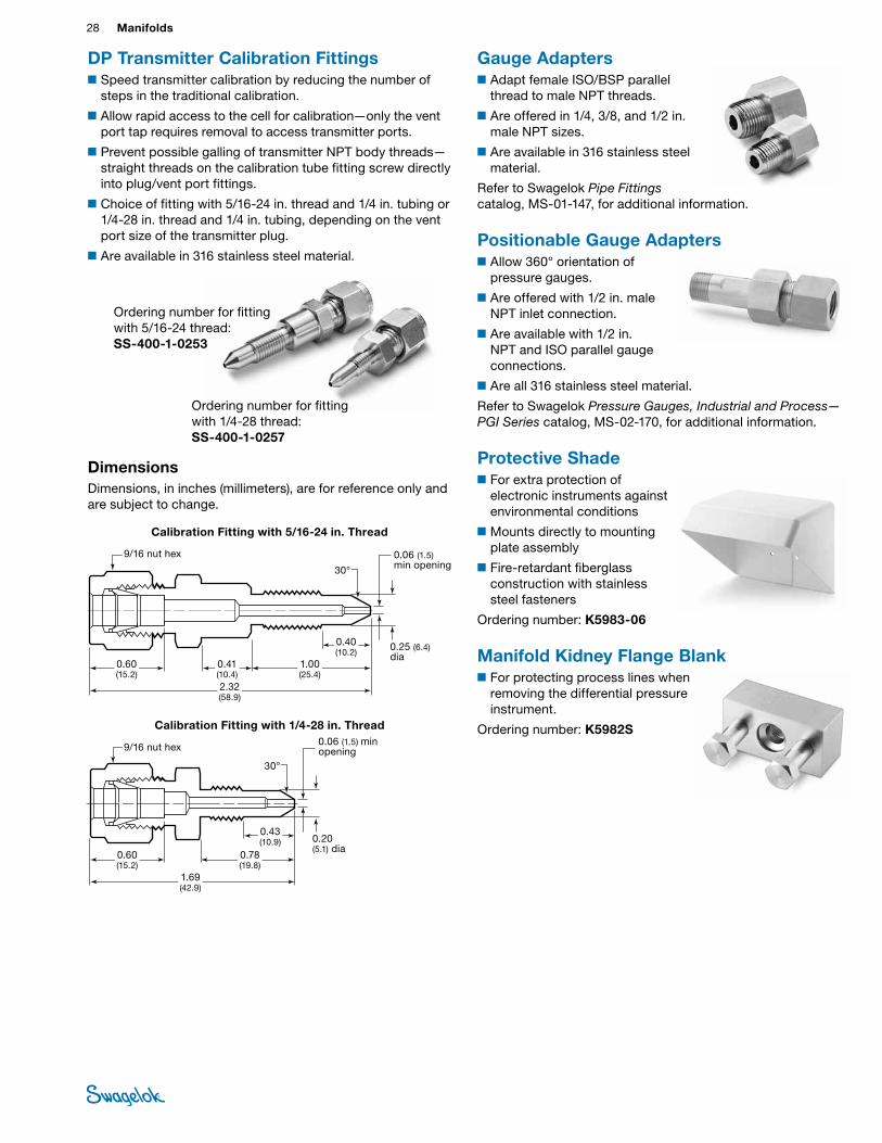
Gauge Adapters■Adapt female ISO/BSP parallel
thread to male NPT threads.
■Are offered in 1/4, 3/8, and 1/2 in. male NPT sizes.
■Are available in 316 stainless steel material.
Refer to Swagelok Pipe Fittings catalog, MS-01-147, for additional information.
Positionable Gauge Adapters■Allow 360° orientation of
pressure gauges.
■Are offered with 1/2 in. male NPT inlet connection.
■Are available with 1/2 in. NPT and ISO parallel gauge connections.
■Are all 316 stainless steel material.
Refer to Swagelok Pressure Gauges, Industrial and Process—PGI Series catalog, MS-02-170, for additional information.
Protective Shade■For extra protection of
electronic instruments against environmental conditions
■Mounts directly to mounting plate assembly
■Fire-retardant fiberglass construction with stainless steel fasteners
Ordering number: K5983-06
Manifold Kidney Flange Blank■For protecting process lines when
removing the differential pressure instrument.
Ordering number: K5982S
DP Transmitter Calibration Fittings■Speed transmitter calibration by reducing the number of
steps in the traditional calibration.
■Allow rapid access to the cell for calibration—only the vent port tap requires removal to access transmitter ports.
■Prevent possible galling of transmitter NPT body threads—straight threads on the calibration tube fitting screw directly into plug/vent port fittings.
■Choice of fitting with 5/16-24 in. thread and 1/4 in. tubing or 1/4-28 in. thread and 1/4 in. tubing, depending on the vent port size of the transmitter plug.
■Are available in 316 stainless steel material.
Ordering number for fitting with 1/4-28 thread: SS-400-1-0257
Ordering number for fitting with 5/16-24 thread: SS-400-1-0253
DimensionsDimensions, in inches (millimeters), are for reference only and are subject to change.
0.60 (15.2)
0.41 (10.4)2.32 (58.9)
1.00 (25.4)
0.25 (6.4) dia
9/16 nut hex
30°
0.06 (1.5) min opening
0.40 (10.2)
Calibration Fitting with 5/16-24 in . Thread
Calibration Fitting with 1/4-28 in . Thread
0.60 (15.2)
0.78 (19.8)
1.69 (42.9)
0.20 (5.1) dia
30°
0.06 (1.5) min opening
0.43 (10.9)
9/16 nut hex

Instrument Manifold Systems 29 INSTRUM
ENT M
ANIFOLD SYSTEM
S
Filling Connector■With integral, soft-seated nonreturn valve
■Suitable for direct bolting to the flange face of pressure transmitters
■6 mm or 1/4 in. tube fitting with retained cap
■Supplied complete with 2 × 7/16-20 bolts, PTFE flange seal, plug, and retaining chain
■Pressure-temperature ratings: 6000 psig (413 bar) at 100°F (37°C) 4000 psig (275 bar) at 400°F (204°C)
Ordering Information
Description Ordering NumberG1/4 with 1/4 in. Swagelok
tube fitting installed K5837S0003
G1/4 with 6 mm Swagelok tube fitting installed K5837S0005
Seal Pot with Integral Vent valve■Liquid chamber of 50 cm3
■Valve fitted with high-temperature graphite packing and seals
■Process and vent connections: 1/4 in. ISO parallel thread (G1/4) with locking pins and gasket
■Pressure-temperature ratings: 6000 psig (413 bar) at 100°F (37°C) 3000 psig (206 bar) at 842°F (450°C)
■Factory-installed and tested Swagelok tube fittings with locking pin and gasket available
Ordering Information
Description Ordering Number
G1/4 ISO parallel thread S5986S0001
G1/4 with 3/8 in. Swagelok tube fittings
installedS5986S0003
G1/4 with 10 mm with Swagelok tube fittings
installedS5986S0005
2-valve V, VE
2-valve remote, 2 valve pressure
3-valve V traditional, VE
3-valve V compact3-valve VL
5-valve V
4-valve DP
purge block double purge block seal pot
4-valve DP 2-valve DP pressure manifold
5-valve VB 5-valve VE
Vent
Additional Manifold ProductsFor bellows-sealed 3-valve manifolds, refer to Swagelok Bellows-Sealed 3-Valve Manifolds—V3 Series catalog, MS-02-07. The manifolds use B or U series bellows-sealed valves for systems with difficult fluid containment requirements.
Caution: Do not mix or interchange parts with those of other manufacturers .
MS-02-445, RevD, April 2018

IntroductionSince 1947, Swagelok has designed, developed, and manufactured high-quality, general-purpose and specialty fluid system products to meet the evolving needs of global industries. Our focus is on understanding our customers’ needs, finding timely solutions, and adding value with our products and services.
We are pleased to provide this global edition of the book-bound Swagelok Product Catalog, which compiles more than 100 separate product catalogs, technical bulletins, and reference documents into one convenient, easy-to-use volume. Each product catalog is up to date at the time of printing, with its revision number shown on the last page the individual catalog; for example, the Swagelok Gaugeable Tube Fittings and Tube Adapters catalog is MS-01-140, RevW. Subsequent revisions will supersede the printed version and will be posted on the Swagelok website and in the Swagelok elec-tronic Desktop Technical Reference (eDTR) tool.
For more information, visit your Swagelok website or contact your authorized Swagelok sales and service representative.
Safe Product SelectionWhen selecting a product, the total system design must be considered to ensure safe, trouble-free performance. Function, material compatibility, adequate ratings, proper installation, operation, and maintenance are the responsibilities of the system designer and user.
Warranty InformationSwagelok products are backed by The Swagelok Limited Lifetime Warranty. For a copy, visit swagelok.com or contact your authorized Swagelok representative.
Swagelok, Ferrule-Pak, Goop, Hinging-Collecting, IGC, Kenmac, Micro-Fit, Nupro, Snoop, Sno-Trik, SWAK, VCO, VCR, Ultra-Torr, Whitey—TM Swagelok Company15-7 PH—TM AK Steel Corp.AccuTrak, Beacon, Westlock—TM Tyco International ServicesAflas—TM Asahi Glass Co., Ltd.AL-6XN—TM Allegheny Ludlum CorporationASCO, El-O-Matic—TM EmersonAutoCAD—TM Autodesk, Inc.CSA—TM Canadian Standards AssociationCrastin, DuPont, Kalrez, Krytox, Teflon, Viton—TM E.I. duPont Nemours and CompanyDeviceNet—TM ODVADyneon, Elgiloy, TFM—TM Dyneon Elgiloy—TM Elgiloy Specialty Metals FM—TM FM GlobalGrafoil—TM GrafTech International Holdings, Inc.Honeywell, MICRO SWITCH—TM HoneywellMAC—TM MAC ValvesMicrosoft, Windows—TM Microsoft Corp.NACE—TM NACE InternationalPH 15-7 Mo, 17-7 PH—TM AK Steel Corppicofast—Hans Turck KGPillar—TM Nippon Pillar Packing Company, Ltd.Raychem—TM Tyco Electronics Corp.Sandvik, SAF 2507—TM Sandvik ABSimriz—TM Freudenberg-NOKSolidWorks—TM SolidWorks CorporationUL—Underwriters Laboratories Inc.Xylan—TM Whitford Corporation© 2017 Swagelok Company
Caution: Do not mix or interchange parts with those of other manufacturers.