Instrument hardware control valves
47
Petrofac Training Training. Competence. Excellence. Instrument Hardware: Control Valves Unit I-10
-
Upload
mohammed-enab -
Category
Engineering
-
view
268 -
download
6
Transcript of Instrument hardware control valves

Petrofac Training
Training. Competence. Excellence.
Instrument Hardware:Control ValvesUnit I-10

Unit I-10: Control Valves
Unit I-10: Control Valves
Objectives
At the end of this unit, the trainee will be able to:
Identify types of control valves
Understand their control functions

Unit I-10: Control Valves
Introduction

Unit I-10: Control Valves
Components of a Control Valve

Unit I-10: Control Valves
Valves can be activated using several different types of energy:
- Human
- Pneumatic Energy
- Electrical Energy
- Hydraulic Energy

Unit I-10: Control Valves
The most important advantages of pneumatic control valves are:
- The construction is simple and robust.
- The power output produced by the actuator is effective and direct.
- The valve needs relatively little maintenance.

Unit I-10: Control Valves
Valve Actuator
Actuators are designed so that when the controller signal output is increased to the control valve, it will either lower or raise the valve stem.

Unit I-10: Control Valves

Unit I-10: Control Valves
Bonnet and Gland Assembly
The middle part of a control valve is known as the Valve Bonnet.
The packing material is held in a Gland Assembly.

Unit I-10: Control Valves
Valve Bonnet and Gland Assembly

Unit I-10: Control Valves
Valve Body
Two most common types are:

Unit I-10: Control Valves
Contoured Plug
Unit I-10: Control Valves
V-Port Plug

Unit I-10: Control Valves
Advantages and Disadvantages
- Flow In Contoured Plug is evenly spread over plug surface area but flow in V-Port is localized and can cause erosion problem.
- V-Port can be more easily ‘characterised’.
- V-Port is lighter than the solid contoured plug and easier to manufacture.
- V-Port accumulate dirt and sludge. The design of the contoured plug make this impossible.

Unit I-10: Control Valves
Single and Double Seat Arrangements

Unit I-10: Control Valves
Single Seat Contoured Plug

Unit I-10: Control Valves
Double Seat Contoured Plug
Unit I-10: Control Valves
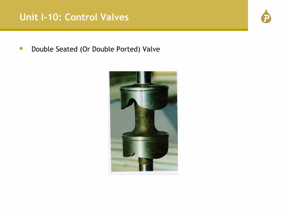
Double Seated (Or Double Ported) Valve

Unit I-10: Control Valves
Different Types of Valve Plugs

Unit I-10: Control Valves
Fluted Valve Plug

Unit I-10: Control Valves
Cage Guided Valve Plug
Unit I-10: Control Valves
Hand-wheels are for manual positioning of the valve plugs:
- On failure of air supply to actuator
- During start-up
- During an emergency
- When the control valve is not provided with a bypass valve.

Unit I-10: Control Valves
Control Valve with Hand-wheel
Unit I-10: Control Valves
Valve Lift/Flow Characteristics

Unit I-10: Control Valves
Semi throttle Characteristics‑

Unit I-10: Control Valves
Main process applications of equal percentage characteristic valve
‐ Linearisation of Flow Loops
‐ Uncertain Flow Conditions
Unit I-10: Control Valves
Relationship between Equal Percentage and Linear Characteristics

Unit I-10: Control Valves
Special Types of Control Valves

Unit I-10: Control Valves
Butterfly Valve

Unit I-10: Control Valves
Ball Valve

Unit I-10: Control Valves
Three Way Valve
3‐way Valve is used for flow diversion and mixing purposes.
Unit I-10: Control Valves
Three Way Valve
Unit I-10: Control Valves
Energised Solenoid Valve

Unit I-10: Control Valves
De‐energised Solenoid Valve

Unit I-10: Control Valves
Furnace Firing Control Loop

Unit I-10: Control Valves
Valve Activation

Unit I-10: Control Valves
Valve Activation
Unit I-10: Control Valves
Valve Activation

Unit I-10: Control Valves
Valve Activation

Unit I-10: Control Valves
Valve actions by colour coding

Unit I-10: Control Valves
Robotarm Safety Shutdown Valve

Unit I-10: Control Valves
Motor Operated Valves

Unit I-10: Control Valves
Valve Positioners
Unit I-10: Control Valves
Use of a valve positioner:
‐ When a cylinder actuator requires air pressure in excess of 15 psi
‐ When a valve is split ranged.
‐ When valves are operated in a reverse acting mode.
‐ When expected dead band of the actuator/valve combination exceeds 5% of signal span.
‐ When a booster has to be used for high stroking speed and may have excessive dead band.
Unit I-10: Control Valves
Why a valve positioner should be used?
‐ To increase the speed of response in case a valve is located too far away from a control room installed I/P transducer.

Petrofac Training
Training. Competence. Excellence.
Instrument Hardware:Control ValvesUnit I‐10