INSTRUCTIONS ON INSTALLATION OPERATION AND …€¦ · instructions on installation operation and...
45
INSTRUCTIONS ON INSTALLATION OPERATION AND MAINTENANCE FOR KIRLOSKAR PUMP TYPE CPHM KIRLOSKAR BROTHERS LIMITED UDYOG BHAVAN, TILAK ROAD, PUNE - 411 002
Transcript of INSTRUCTIONS ON INSTALLATION OPERATION AND …€¦ · instructions on installation operation and...

INSTRUCTIONS ON INSTALLATIONOPERATION ANDMAINTENANCE FORKIRLOSKAR PUMPTYPE CPHM
KIRLOSKAR BROTHERS LIMITEDUDYOG BHAVAN, TILAK ROAD, PUNE - 411 002

IOM/CPHM/0002/02 Issue Date: 25/09/2000 Page: Page 1 of 35 Last Revision Date:
KIRLOSKAR BROTHERS LIMITED Udyog Bhavan, Tilak Road, Pune 411 002 (India)
WARRANTY
We warrant that the pump supplied by us is free from defective material and faulty workmanship. This warranty holds good for a period of 12 months from the date of commissioning of the equipment or 18 months from the date of despatch from our factory, whichever is earlier. Our liability in respect of any complaint is limited to replacing part/parts free of charge ex-works or repairs of the defective part/parts only to the extent that such replacement / repairs are attributable to or arise solely from faulty workmanship or defective material. The warranty holds good only for the products manufactured by us.
KIRLOSKAR BROTHERS LIMITED
IOM/CPHM/0002/02 Issue Date: 25/09/2000 Page: Page 2 of 35 Last Revision Date:
CONTENTS 1. GENERAL
2. INSTALLATION
3. TECHNICAL DATA
4. MAINTENANCE
5. OVERHAULING
6. SPECIFICATION LIST AND CROSS-SECTIONAL DRAWING
7. OPERATION CAUTION THIS INSTRUCTION MANUAL COVERS THE GENERAL REQUIREMENTS OF
INSTALLATION, OPERATION AND MAINTENANCE. HOWEVER THE END USER SHOULD REFER TO THE DRAWINGS AND DOCUMENTS IF SUPPLIED AGAINST SPECIFIC ORDER.
PLEASE FURNISH PUMP TYPE, NAME OF THE PART, PART NUMBER, MATERIAL
CONSTRUCTION AND OTHER NAME PLATE DETAILS WHILE ORDERING SPARE PARTS FOR THE PUMP.

IOM/CPHM/0002/02 Issue Date: 25/09/2000 Page: Page 3 of 35 Last Revision Date:
1. GENERAL 1.1 The booklet covers instructions for following pump types of CPHM series.
UNIT-4 UNIT-5 UNIT-7 UNIT-9 UNIT-11 UNIT-11A UNIT-11B UNIT-13
20/13*
20/16*
20/20*
32/13
32/16
32/16A
32/20
32/20A
40/13
40/16
40/20
40/20A
50/13
50/16
50/16A
50/20
65/13
25/26A
32/26
40/26
40/32
50/26
50/32
65/16
65/20
65/26
65/26N
80/16
80/20
80/26
100/20
65/32
65/40A
80/32
80/40
80/40N
100/26
100/32
100/40
125/26
125/32
125/40
125/40N
150/32
150/32N
150/40
65/43
125/26
[2900
RPM]
125/45 150/43 150/50M
200/38M
200/46
150/52
NOTES:
1. CPHM pumps with driving unit-11, 11A, 11B and 13 are supplied with oil lubrication bearings as a standard supply.
2. *marked pumps are supplied with semi-open type impeller only as a standard
supply. 3. Pump models with suffix “N” are modified for improvement in rising nature
performance towards shut-off. 1.2 Description of ‘CPHM’ pumps:
KIRLOSKAR CPHM pumps are of back pullout design which enables to remove the rotating unit of the pump for inspection and repairs without disturbing the pipe connections.
1.3 The complete range of CPHM pumps is covered by eight driving units thereby reducing
inventory and achieving interchangeability of parts. 1.4 Pumps when properly installed and given due care in operation and maintenance
should operate satisfactorily for a long period. 1.5 When the pump is received, sometime before the actual use, it should be inspected
and located in a dry place. The coupling should be rotated once in a month to prevent pitting of bearing surfaces.
2. INSTALLATION 2.1 For location, preparing foundation, installation, alignment, piping, general maintenance,
trouble publication ‘GENERAL INSTRUCTIONS FOR INSTALLATION, OPERATION AND MAINTENANCE OF KIRLOSKAR CENTRIFUGAL PUMPS’ which is also printed

IOM/CPHM/0002/02 Issue Date: 25/09/2000 Page: Page 4 of 35 Last Revision Date:
STEEL STRAIGHT EDGEINCORRECT PARALLEL
MISALIGNMENT
STEEL STRAIGHT EDGESTEEL STRAIGHT EDGE
INCORRECT ANGULAR MISALIGNMENT
3mm
CORRECT
alongwith this booklet must be followed carefully. If the pump is drawing liquid from the vessel under vacuum, then vacuum equalising connection piping must be made as per instructions given in above publication. The external sealing connection to the pump, if applicable, must be made after installing and before commissioning the pump.
2.2 Mounting and alignment: A spacer type flexible coupling is recommended to connect pump shaft to the driver.
By using spacer type coupling, the complete rotating unit can be removed from the volute without removing pump casing or motor and without disconnecting piping connections. This also avoids any re-alignment of pump and motor after reassembly of rotating unit. However other types of coupling can be supplied against request.
Alignment: ALWAYS REMEMBER “FLEXIBLE COUPLING IS NOT A UNIVERSAL JOINT”. Correct alignment is essential for the smooth operation of the pump. There are two
types of mis-alignment between the pump shaft and the drive shaft which are –
i. Angular mis-alignment- Shaft with axis concentric but not parallel. ii. Parallel mis-alignment – Shaft with axis parallel but not concentric. Mis-
alignment is checked by using straight edge as shown in FIG.1 at 90° apart.
SPACER COUPLING
STD COUPLING
Fig. 1
STEEL STRAIGHT EDGE
INCORRECT ANGULAR MISALIGNMENT
STEEL STRAIGHT EDGEINCORRECT PARALLEL
MISALIGNMENT
STEEL STRAIGHT EDGE
3mm
CORRECT

IOM/CPHM/0002/02 Issue Date: 25/09/2000 Page: Page 5 of 35 Last Revision Date:
2.3.1 The pipe connections are flushed and tightened properly. 2.3.2 Alignment is proper. 2.3.3 Auxiliary piping connection such as sealing / flushing etc. are made. 2.3.4 ‘CPHM’ pumps are grease lubricated as standard supply. However against specialty oil
lubrication can be given. Then the pump is provided with constant level oiler. Please note that CPHM pumps in units -11, 11A and 11B and CPHM-13 are always with oil lubrication.
2.3.4.1 Constant level oiler:
Fix the constant level oiler and fill the oil. Procedure for fitting the constant level oiler and method of filling oil is given below. Constant level oiler has plastic container and aluminum body as a standard supply. Connection stem is ¼” BSP tapped and its capacity is 70ml approx. If the constant level oiler is properly fitted and oil is filled as per instructions given, practically no attention is required as far as lubrication of bearing is concerned other than to replenish the visible reserve supply of the oil in the container (Refer Fig.2, 3 and 4).
2.3.4.2 Method of fitting:
Screw constant level oiler stem into the tapped hole of the bearing housing reservoir. Before fitting oiler, check the level of the tapped hole with the help of turn bar with ¼” BSP tapping at one end and a sprit level (see Fig.2). If the level is incorrect and oiler tilts downward, oil will not flow from oiler into the reservoir. (see Fig.3). Hence it is necessary to check the level before fitting in the constant level oiler.
2.3.4.3 Method of filling the oil: Tilt the container (as shown in Fig.4) and fill it with oil through step of the oiler. Replace the container and allow oil to flow into the reservoir. The oil in the container shall flow into the bearing housing reservoir and shall become empty. Repeat above procedure till the level in the reservoir is equal to the level of which the oiler is adjusted. When the desired level is attained the oil in container shall remain steady at a position. Visible level of the oil in the container indicates that bearing housing reservoir is filled up to the mark.

IOM/CPHM/0002/02 Issue Date: 25/09/2000 Page: Page 6 of 35 Last Revision Date:
CAUTION
1. In no case oil should be filled in directly into the bearing housing reservoir, through breather cap.
2. Replenish the visible reserve supply of oil in the container as oil is used up.
3. Please ensure that “Air Groove” provided on aluminum body on which plastic
container rests, is not clogged with dust / fiber oil film etc. This groove allows atmospheric air to enter inside the body to maintain oil level in bearing housing.
SPIRITLEVEL
Fig. No.2 CORRECT METHOD
Fig. No.3 INCORRECT METHOD
Fig. No.4
ALWAYS FILL OIL HERE
NEVER FILL OIL HERE
IOM/CPHM/0002/02 Issue Date: 25/09/2000 Page: Page 7 of 35 Last Revision Date:
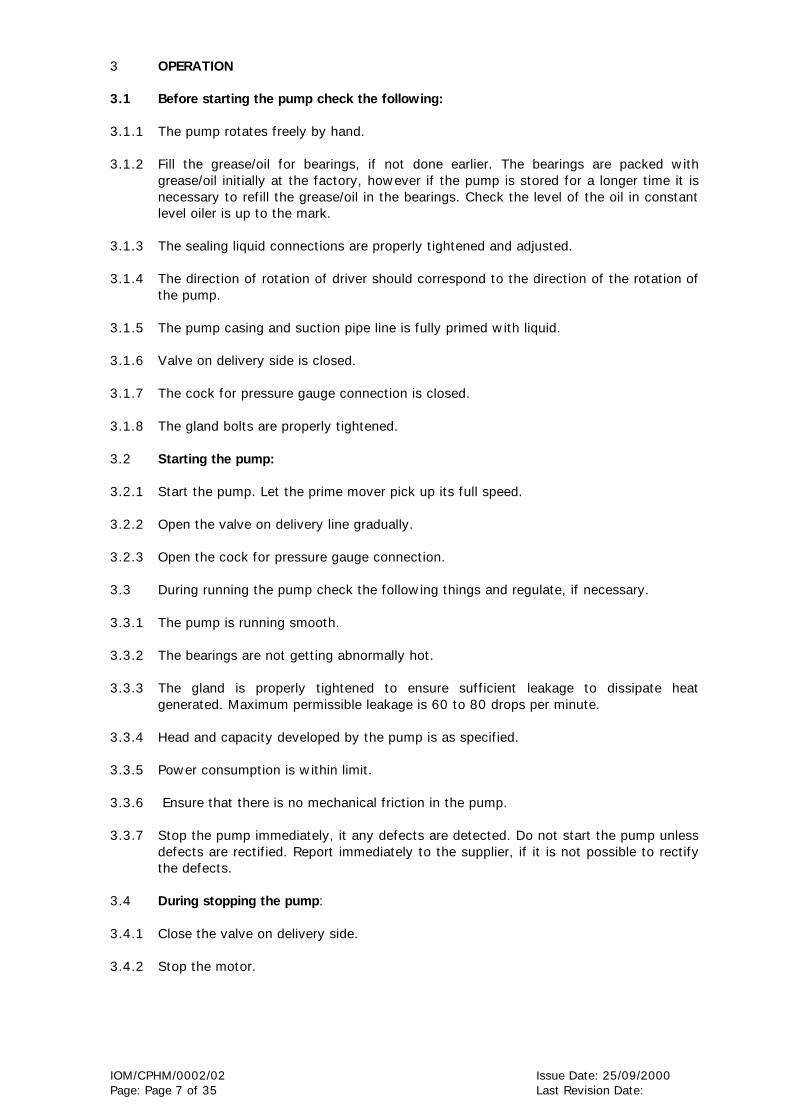
3 OPERATION 3.1 Before starting the pump check the following: 3.1.1 The pump rotates freely by hand. 3.1.2 Fill the grease/oil for bearings, if not done earlier. The bearings are packed with
grease/oil initially at the factory, however if the pump is stored for a longer time it is necessary to refill the grease/oil in the bearings. Check the level of the oil in constant level oiler is up to the mark.
3.1.3 The sealing liquid connections are properly tightened and adjusted. 3.1.4 The direction of rotation of driver should correspond to the direction of the rotation of
the pump. 3.1.5 The pump casing and suction pipe line is fully primed with liquid. 3.1.6 Valve on delivery side is closed. 3.1.7 The cock for pressure gauge connection is closed. 3.1.8 The gland bolts are properly tightened. 3.2 Starting the pump: 3.2.1 Start the pump. Let the prime mover pick up its full speed. 3.2.2 Open the valve on delivery line gradually. 3.2.3 Open the cock for pressure gauge connection. 3.3 During running the pump check the following things and regulate, if necessary. 3.3.1 The pump is running smooth. 3.3.2 The bearings are not getting abnormally hot. 3.3.3 The gland is properly tightened to ensure sufficient leakage to dissipate heat
generated. Maximum permissible leakage is 60 to 80 drops per minute. 3.3.4 Head and capacity developed by the pump is as specified. 3.3.5 Power consumption is within limit. 3.3.6 Ensure that there is no mechanical friction in the pump. 3.3.7 Stop the pump immediately, it any defects are detected. Do not start the pump unless
defects are rectified. Report immediately to the supplier, if it is not possible to rectify the defects.
3.4 During stopping the pump: 3.4.1 Close the valve on delivery side. 3.4.2 Stop the motor.
IOM/CPHM/0002/02 Issue Date: 25/09/2000 Page: Page 8 of 35 Last Revision Date:
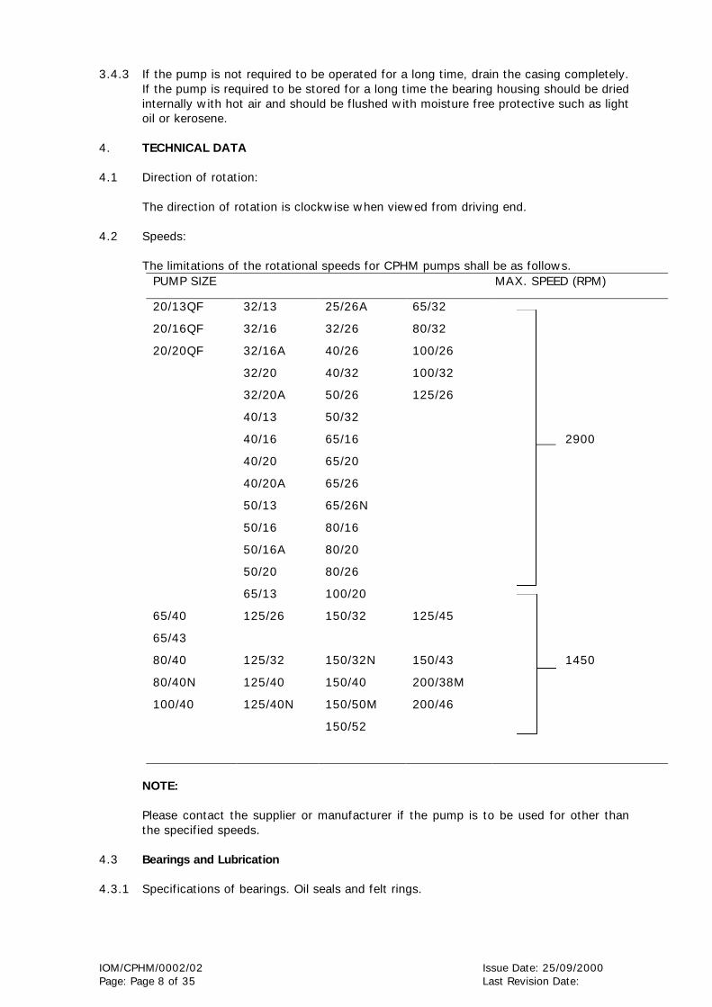
3.4.3 If the pump is not required to be operated for a long time, drain the casing completely.
If the pump is required to be stored for a long time the bearing housing should be dried internally with hot air and should be flushed with moisture free protective such as light oil or kerosene.
4. TECHNICAL DATA 4.1 Direction of rotation:
The direction of rotation is clockwise when viewed from driving end.
4.2 Speeds:
The limitations of the rotational speeds for CPHM pumps shall be as follows.
PUMP SIZE MAX. SPEED (RPM)
20/13QF
20/16QF
20/20QF
65/40
65/43
80/40
80/40N
100/40
32/13
32/16
32/16A
32/20
32/20A
40/13
40/16
40/20
40/20A
50/13
50/16
50/16A
50/20
65/13
125/26
125/32
125/40
125/40N
25/26A
32/26
40/26
40/32
50/26
50/32
65/16
65/20
65/26
65/26N
80/16
80/20
80/26
100/20
150/32
150/32N
150/40
150/50M
150/52
65/32
80/32
100/26
100/32
125/26
125/45
150/43
200/38M
200/46
2900
1450
NOTE: Please contact the supplier or manufacturer if the pump is to be used for other than the specified speeds.
4.3 Bearings and Lubrication 4.3.1 Specifications of bearings. Oil seals and felt rings.

IOM/CPHM/0002/02 Issue Date: 25/09/2000 Page: Page 9 of 35 Last Revision Date:
PART No. DESCRIPTION UNIT-4 UNIT-5 UNIT-7 UNIT-9 UNIT11,11A,11B UNIT-13
502.1 Felt ring (DE) - 25 x 38 x 6T 43 x 30 x 6T 40 x 53 x 6T - -
502.2. Felt ring (NDE) - 25 x 38 x 6T 35 x 47 x5T 45 x 58 x 6T - -
500.1 Oil Seal (DE) 18 x 35 x 7 25 x 37 x 7 32 x 45 x 7 72 x 42 x 10 72 x 50 x 10 60 x 85 x 13
500.2 Oil Seal (NDE) 18 x 35 x 7 25 x 37 x 7 32 x 47 x 7 60 x 45 x 8 72 x 50 x 10 65 x 85 x 13*
4.3.2. Bearing Details:
BEARING SIZE DRIVING UNIT NO.
SPEED IN RPM
BEARING ARRANGEMENT
END DRIVING END NON DRIVING
4 5 7 9
11
11A
11B
13
Upto 3000 rpm
Upto 3000 rpm
Upto 3000 rpm
Upto 3000 rpm
Upto 3000 rpm
Upto 1500 rpm
Upto 1500 rpm
Upto 1500 rpm
Standard supply
Standard supply
Standard supply
Standard supply
Standard supply
Standard supply
Standard supply
Standard supply
SKF-6304 (1 No.) AND
SKF-7304B (1 No.)
SKF-6305
(1 No.)
SKF-3307 (1 No.)
SKF-3309BG
(1 No.) SKF-3311
(1 No.)
SKF-7311BECP 2 No./1 pair
SKF-7311BECP
2 No./1 pair
SKF-7313BG 2 No./1 pair
SKF-6304 (1 No.)
SKF-6305 (1 No.)
SKF-NU307
(1 No.)
SKF-NU309 (1 No.)
SKF-NU311 (1 No.)
SKF-NU311
(1 No.)
SKF-NU311 (1 No.)
SKF-NU313
(1 No.) NOTES:
1. Bearings of SKF make or equivalent are used. 2. The bearing arrangement mentioned above are suitable for suction pressure less
than 2 kg/cm2. For application involving suction pressure above 2 kg/Cm2 please refer to Unit Sales, Kirloskarvadi.
3. C3 clearance bearings are used. 4. Axial running clearance shall be less than 0.45 mm for all above bearing
arrangements. 5. Maximum allowable temperature of bearings shall be 80° C. 6. Bearings are grease lubricated for unit Nos. 4,5,7 and 9 and oil lubricated for unit-
11 and 13 pumps. Oil level in the bearing housing is maintained upto the desired level with the help of constant level oiler. Constant level oiler is our standard supply.

IOM/CPHM/0002/02 Issue Date: 25/09/2000 Page: Page 10 of 35 Last Revision Date:
4.3.2 Lubrication of bearings: Lubrication with grease: Bearings are grease lubricated. Following are the details of grease grade to be used.
MANUFACTURER SPEED
INDIAN OIL
HINDUSTAN PETROLEUM
CALTEX
1500 RPM
SERVOGEM-3
NATRA-3 OR LITHON-3
STARFAX-3
3000 RPM
SERVOGEM-2
NATRA-2 OR LITHON-2
STARFAX-2
Quantity of grease:
DRIVING UNIT
QUANTITY APPROX. (GRAMS)
4 5 7 9
5 6 10 14
Lubrication with oil: Bearings are oil lubricated. Following are the details of oil grade to be used.
MANUFACTURER SPEED
1500 RPM 3000 RPM
INDIAN OIL SERVOSYSTEM-100 SERVOSYSTEM-68
HINDUSTAN PETROLEUM
ENKLO-57
ENKLO-53
Quantity of oil:
DRIVING UNIT QUANTITY APPROX. (LITERS)
4 5 7 9 11 13
: : : : : :
0.2 0.4 0.5 0.7 1.0 1.5
4.3.3 Bearing temperature:
A) Maximum allowable temperature of bearings is 35°C above ambient. B) In case of new bearings, renew grease/oil after about 200 hours and then after
twice in a year, if bearing temperature is always below 50°C and there is only small risk of contamination. If the bearing temperature is upto 80°C and if there is danger of contamination, the grease/oil should be renewed after about every 3 months.
4.4 Specification of stuffing box packing, gaskets and “O” rings:
(Refer Chart No. 4.4(a), 4.4(b), 4.4(c) on the next page.)

IOM/CPHM/0002/02 Issue Date: 25/09/2000 Page: Page 11 of 35 Last Revision Date:
CPH
M 2
0/2
0 Q
F
230D
x 2
16D
x 1
T
CPH
M 2
0/1
6 Q
F
188D
x 1
76 D
x 1
T
CPH
M-4
UN
IT
CPH
M 2
0/1
3 Q
F
2 +
L +
3
44D
x 2
8D
x 8
T
115
152D
x 1
41D
x 1
T
85D
x 5
2D
x 1
T
230D
x 1
71D
x 1
T
60 ID
x 3
T
DES
CRIP
TIO
N
Gla
nd p
acki
ng a
rran
gem
ent
with
lant
ern
ring
Gla
nd p
acki
ng s
ize
Str
aigh
t le
ngth
of
one
glan
d pa
ckin
g in
mm
Gas
ket
for
pum
p ca
sing
&
impe
ller
nut
Gas
ket
for
bear
ing
cove
r sh
aft
sl
eeve
Gas
ket
for
impe
ller
‘O’
ring
for
Bea
ring
Car
trid
ge
4.4
(a)
S
PEC
IFIC
ATIO
N O
F STU
FFIN
G B
OX
PA
CK
ING
, G
ASK
ETS &
‘O
’ RIN
GS F
OR C
PHM
-4 U
NIT
PU
MPS
PART N
O.
----
---
4300001
----
--
5110001
5140001
5150001
5230101
NO
TE
: A
LL D
IMEN
SIO
NS A
RE
IN M
M

IOM/CPHM/0002/02 Issue Date: 25/09/2000 Page: Page 12 of 35 Last Revision Date:
431 ID
x
450 O
D
x 1 T
H
411 ID
x
432 O
D
x 1 T
H
331 ID
x
348 O
D x
1 T
H CPH
M 9
65/43
65/40
150/40
125/40
100/40
80/40
150/32
125/32
100/32
80/32
65/32
125/26
100/26
2 +
L +
3
75 x
55 x
10 T
HIC
K
205
266 ID
x
282 O
D
x 1 T
H
124 x
134 x
1 T
H
50 O
D x
44 ID
x 1
TH
76 ID
x 9
4 O
D x
1 T
145 ID
x 3
TH
150 ID
x 3
T
265 ID
x 3
TH
108 ID
x3 T
H
48 O
D x
38
ID x
1TH
99 O
D x
55 ID
x 1
TH
331 ID
x
348 O
D x
1 T
H
266 ID
x
282 O
D x
1 T
H
216 ID
x
230 O
D x
1 T
H C
PHM
7
50/32
40/32
25/26
80/20
65/26
50/26
40/26
32/26
100/20
80/20
65/20
80/16
65/16
2 +
L +
3
65 x
45 x
10 T
HIC
K
180
176 ID
x
188 O
D x
1 T
H
112 x
102 X
1 T
H
40 O
D x
35 ID
x 1
TH
76 ID
x 9
4 O
D x
1 T
123 ID
x 3
TH
150 ID
x 3
T
175 ID
x
215 ID
x
285 ID
x
3 T
H
3 T
H
3 T
H
88 ID
x 3
TH
38 O
D x
28 ID
x 1
TH
99 O
D x
55 ID
x 1
TH
216 ID
x
230 O
D x
1 T
H
215 ID
x
3 T
H
176 ID
x
188 O
D x
1 T
H
175 ID
x
3 T
H
UN
IT N
O.
CPH
M 5
50/20
40/20
32/20
50/16
40/16
32/16
65/13
50/13
40/13
32/13
2 +
L +
3
51 x
35 x
8 T
HIC
K
140
114 ID
x
152 O
D x
1 T
H
78 S
Q x
1 T
30 O
D x
25 ID
x 1
TH
52 ID
x 6
4 O
D x
1 T
104 ID
x 3
TH
125 ID
x 3
T
142 ID
x
3 T
H
72 ID
x 3
TH
.
28 O
D X
20 ID
x 1
TH
99 O
D x
55 ID
x 1
TH
DES
CRIP
TIO
N
GLA
ND
PA
CK
ING
ARRG
T.
WIT
H
LAN
TER
N R
ING
GLA
ND
PA
CK
ING
SIZ
E (O
.D.
x I.D
. x
TH
ICK
)
STRA
IGH
T L
ENG
TH
OF
GLA
ND
PA
CK
ING
IN m
m.
GA
SK
ET F
OR C
ASIN
G &
CA
SIN
G
CO
VER
GA
SK
ET F
OR B
EARIN
G C
OV
ER
GA
SK
ET F
OR IM
PELL
ER A
ND
SH
AFT
SLE
EVE
GA
SK
ET F
OR M
ECH
. SEA
L
“O”
RIN
G F
OR C
ASIN
G C
OV
ER
“O”
RIN
G F
OR B
EARIN
G
HO
USIN
G
‘O’
RIN
G F
OR L
AN
TER
N B
RA
CK
ET
‘O’
RIN
G F
OR B
EARIN
G
CA
RTRID
GE
GA
SK
ET F
OR IM
PELL
ER A
ND
IM
PELL
ER N
UT
GA
SK
ET F
OR O
IL W
ELL
CO
VER
4.4
(a)
SPE
CIF
ICA
TIO
NS O
F STU
FFIN
G B
OX
PA
CK
ING
GA
SK
ET A
ND
“O
” RIN
G F
OR D
IVID
ING
UN
ITS 5
,7,9
,11,1
3
PART
NO
.
4300001
5110001
5140001
5150001
5160001
5250101
5231101
5250201
5230301
6820001
6850001
NO
TE:
CO
RREC
T L
IQU
ID S
PEC
IFIC
ATIO
NS S
HO
ULD
BE
INFO
RM
ED T
O U
S T
O R
ECO
MM
END
SU
ITA
BLE
GRA
DE
OF
ST.
BO
X P
AC
KIN
G.
ALL
DIM
ENSIO
NS A
RE
IN M
M.

IOM/CPHM/0002/02 Issue Date: 25/09/2000 Page: Page 13 of 35 Last Revision Date:
4.5
M
echa
nica
l sea
l Spe
cific
atio
n:-
pl r
efer
C/S
dra
win
gs s
uppl
ied
agai
nst
orde
r
NO
TE:
CO
RREC
T L
IQU
ID S
PEC
IFIC
ATIO
NS S
HO
ULD
BE
INFO
RM
ED T
O U
S T
O R
ECO
MM
END
SU
ITA
BLE
GRA
DE
OF
ST.
BO
X P
AC
KIN
G.
ALL
DIM
ENSIO
NS A
RE
IN M
M.
520 ID
x 5
40
OD
x 2
TH
685 ID
x 7
10
OD
x 1
TH
460 ID
x 4
90
OD
x 2
TH
CPH
M 1
3
150/52
150/50M
200/46
200/38M
2 +
L +
3
80 x
105 x
12 T
HIC
K
295
402 ID
x 4
25
OD
x 2
TH
140 x
185
X 1
TH
69 O
D x
74 ID
x 1
TH
83 ID
x 9
4 O
D x
1 T
175 ID
x 3
TH
207 ID
x 3
T
308 ID
x 3
TH
----
----
----
-
69 O
D x
56 ID
x 1
TH
99 O
D x
55 ID
x 1
TH
471 ID
x
491 O
D x
1 T
H
454 ID
x 4
74 O
D
x 1 T
H
UN
IT N
O.
CPH
M 1
1,
11B,
11A
125/45
150/43
125/26
2 +
L +
3
75 x
55 x
10 T
HIC
K
205
266 ID
x 2
82 O
D
x 1 T
H
146 x
156 x
1T
50 O
D x
44 ID
x 1
TH
76 ID
x 9
4 O
D x
1 T
145 ID
x 3
TH
150 ID
x 3
T
265 ID
x 3
TH
----
----
----
---
48 O
D X
38 ID
x 1
TH
99 O
D x
55 ID
x 1
TH
DES
CRIP
TIO
N
GLA
ND
PA
CK
ING
ARRG
T.
WIT
H
LAN
TER
N R
ING
GLA
ND
PA
CK
ING
SIZ
E (O
.D.
x I.D
. x
TH
ICK
)
STRA
IGH
T L
ENG
TH
OF
GLA
ND
PA
CK
ING
IN m
m.
GA
SK
ET F
OR C
ASIN
G &
CA
SIN
G
CO
VER
GA
SK
ET F
OR B
EARIN
G C
OV
ER
GA
SK
ET F
OR IM
PELL
ER A
ND
SH
AFT
SLE
EVE
GA
SK
ET F
OR M
ECH
. SEA
L
“O”
RIN
G F
OR C
ASIN
G C
OV
ER
“O”
RIN
G F
OR B
EARIN
G H
OU
SIN
G
‘O’
RIN
G F
OR L
AN
TER
N B
RA
CK
ET
‘O’
RIN
G F
OR B
EARIN
G C
ARTRID
GE
GA
SK
ET F
OR IM
PELL
ER A
ND
IM
PELL
ER N
UT
GA
SK
ET F
OR O
IL W
ELL
CO
VER
PART N
O.
4300001
5110001
5140001
5150001
5160001
5250101
5231101
5250201
5230301
6820001
6850001
4.4
(a)
SPE
CIF
ICA
TIO
NS O
F STU
FFIN
G B
OX
PA
CK
ING
GA
SK
ET A
ND
“O
” RIN
G F
OR D
IVID
ING
UN
ITS 5
,7,9
,11,1
3
IOM/CPHM/0002/02 Issue Date: 25/09/2000 Page: Page 14 of 35 Last Revision Date:
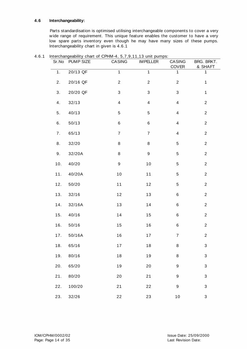
4.6 Interchangeability:
Parts standardisation is optimised utilising interchangeable components to cover a very wide range of requirement. This unique feature enables the customer to have a very low spare parts inventory even though he may have many sizes of these pumps. Interchangeability chart in given is 4.6.1
4.6.1 Interchangeability chart of CPHM-4, 5,7,9,11,13 unit pumps: Sr.No PUMP SIZE CASING IMPELLER CASING
COVER BRG. BRKT. & SHAFT
1.
2.
3.
4.
5.
6.
7.
8.
9.
10.
11.
12.
13.
14.
15.
16.
17.
18.
19.
20.
21.
22.
23.
20/13 QF 20/16 QF 20/20 QF 32/13 40/13 50/13 65/13 32/20 32/20A 40/20 40/20A 50/20 32/16 32/16A 40/16 50/16 50/16A 65/16 80/16 65/20 80/20 100/20 32/26
1 2 3 4 5 6 7 8 8 9
10
11
12
13
14
15
16
17
18
19
20
21
22
1 2 3 4 5 6 7 8 9
10
11
12
13
14
15
16
17
18
19
20
21
22
23
1 2 3 4 4 4 4 5 5 5 5 5 6 6 6 6 7 8 8 9 9 9
10
1 1 1 2 2 2 2 2 2 2 2 2 2 2 2 2 2 3 3 3 3 3 3

IOM/CPHM/0002/02 Issue Date: 25/09/2000 Page: Page 15 of 35 Last Revision Date:
Sr.No PUMP SIZE CASING IMPELLER CASING COVER
BRG. BRKT. & SHAFT
27.
28.
29.
30.
31.
32.
33.
34.
35.
36.
37.
38.
39.
40.
41.
42.
43.
44.
45.
46.
47.
48.
49.
50.
51.
52.
53.
54.
55.
65/26N 80/26 40/32 50/32 25/26A 100/26 125/26 65/32(1450 RPM) 65/32(2900 RPM) 65/40A 65/43 80/32 100/32 125/32 150/32 150/32N 80/40 80/40N 100/40 125/40 125/40N 150/40 125/26\(2900 RPM) 200/38M 200/46 150/50M 125/45 150/43 150/52
25
26
27
28
29
30
31
32
32
34
46
35
36
37
38
38
39
39
40
41
41
42
31
43
44
45
47
48
49
27
28
29
30
31
32
33
34
35
36
48
37
38
39
40
41
42
43
44
45
46
47
33
34
35
36
49
50
51
10
10
11
12
10
13
13
14
12
18
22
14
15
15
16
16
17
17
17
17
17
17
11
19
20
21
23
24
25
3 3 3 3 3 4 4 4 4 4 4 4 4 4 4 4 4 4 4 4 4 4 5 6 6 6 7 8 6

IOM/CPHM/0002/02 Issue Date: 25/09/2000 Page: Page 16 of 35 Last Revision Date:
5. MAINTENANCE:
Preventive maintenance schedule is the periodical checks and precautions by which possibilities of failures and break-down are minimised.
5.1 Daily Checks: 5.1.1 An hourly record of suction and delivery pressure, discharge quantity input to the
pump driver should be maintained. 5.1.2 Bearing temperature, oil level, stuffing box leakage/stuffing box temperature. 5.1.3 Noise and the vibrations are the first signs of impending troubles like cavitaion, air
lock, bearing failure, choking of impeller or casing and such other operating troubles. The pump performance should therefore be checked for noise and the vibrations.
5.2 Periodical checks: 5.2.1 The temperature of the bearing should be measured by a thermometer. Safe maximum
temperature a bearing can attain is 35 ° C above ambient. 5.2.2 The lubricants of the bearings should be checked. The lubricant might get
contaminated with foreign material or get blackened due to overheating. In such cases, bearings should be flushed and charged with fresh lubricants.
5.2.3 Check the stuffing box leakage, normal leakage should be sufficient to dissipate heat
generated. In case the packings are worn out, all the packing rings should be replaced. Replacement of one or two rings of addition rings should never be done.
5.2.4 The alignment of pump unit should be checked. Due to operational vibrations,
atmospheric temperature or stress induced by the weight of piping, the alignment may get disturbed.
5.2.5 Sufficient quantity of suitable type of lubricant and stuffing box packing should be
kept for daily and emergency use. 5.2.6 Calibrate the measuring instruments. 5.3 Annual checks: 5.3.1 The pumps should be overhauled completely to check the clearance and to replace
worn out parts. Clearance between shaft sleeve and throat bush, lantern ring and the shaft sleeve etc. are very important. The bearings should be cleaned thoroughly and lubricated. The stuffing box should be replaced by correctly located the lantern ring.
5.3.2 The effects of liquid handled on pump components should be checked. If abnormal
corrosion, erosion is observed, the component should be replaced with that of suitable material.
5.3.3 The auxiliary pipelines and functioning of the auxiliary systems should be checked. The
main pipe also should be checked for scaling, leakage etc. 5.3.4 The measuring instruments, gauges etc. should be recalibrated. 5.3.5 Full running test may carried out to check whether there is any fault in the
performance, in comparison with original performance.

IOM/CPHM/0002/02 Issue Date: 25/09/2000 Page: Page 17 of 35 Last Revision Date:
5.3.6 Piping supports should be checked so that the pipes do not induce unwanted stresses on the pump.
6 MECHANICAL SEAL IN ‘CPHM’ PUMPS (NOTE THAT MECHANICAL SEALED CPHM
PUMPS ARE SUPPLIED UNDER SPECIFIC ORDER ONLY). 6.1 The mechanical seal is a precision product having been subjected to quality control
throughout all stages of manufacture. The seals are designed to accommodate reasonable tolerances in the equipment but in order to obtain the maximum life with trouble-free performance; the equipment should be adequately maintained. When the mechanical seal is functioning satisfactorily without any leakage etc. the preventive maintenance is not advocated. If leakage occurs, a thorough check-up is needed. While fitting the mechanical seals initially at pump manufacturer’s side, due care is taken and the running test is conducted to ensure the performance of seals. Like other parts in the equipment the mechanical seals are subject to wear at the mating faces of the rotating and stationary ring. The rate of wear will differ with the operating conditions and various other factors such as lubricating property of liquid pumped, the presence of impurities in liquid and other operating conditions. In view of this no firm recommendations can be given for renewal of seal rings/ complete seals. Before re-assembly, please check up the following points to ensure the proper fitting and satisfactory operation of the mechanical seal. 1. Shaft sleeve OD should be within +0.00 mm or –0.05 mm for specified seal
size. 2. Leading edge of shaft sleeve is chamfered. 3. Run out of the shaft at the seal face is within 0.05mm.
6.2 Flushing the mechanical seal face/ product recirculation of liquid at the seal face. Flush fluids are those which are different from the fluid being handled or pumped liquid. If they are introduced from an external source, flushing should be done at pressure at least one atmosphere above the vapour pressure of the liquid at the temperature being pumped. Flushing liquid quantity should be approximately 0.3 to 0.5 m3/hr at the minimum pressure of 0.7 kg/cm2 above pressure of liquid at stuffing box. For specific application refer cross sectional drawing supplied against order. CAUTION: Please refer to the CS drawing supplied against O/A for flushing/ product recirculation recommendation.
6.3 Quenching:
Quench fluids are introduced to the low pressure side of seals for following reasons. a. Cooling to remove heat from stationary seal faces and mechanical seal cover.
b. Smothering to prevent air from reaching the low pressure side of seal face. In
some cases, sealed fluids can react with air to form to sticky residue, which might interfere with seal operation.

IOM/CPHM/0002/02 Issue Date: 25/09/2000 Page: Page 18 of 35 Last Revision Date:
c. Cleaning to remove any accumulation which may develop at the low pressure side of the seal faces.
Quenching liquid media shall be recommended by seal manufacturer. Quench should be supplied at a low pressure of 0.5 to 0.7 Kg/cm2 in order to avoid the leakage of the same through throttle bush. Quench quantity should be approximately 0.3 to 0.5 m3/hr. CAUTION: Please refer to the cross sectional drawing supplied for quenching recommendation if any against order. Throttle bush for mechanical seals: This bush is pressed in the mechanical seal cover. This bush gives protection in case of seal’s failure. Due to the close clearance between bush and shaft sleeve, if the seal fails, the pressure of the product is reduced before it escapes. This bush is also minimizes the quench leakage along the shaft. To avoid possibility of sparking, the bush is made of non-ferrous material as per API-610 specification. This bush is provided for single inside seals only. Flushing at the seal face is necessary to provide lubrication heating, or cooling of the seal faces and densing action. Pump should not run without flushing at the seal face unless specifically recommended by seal manufacturer.
7. OVERHAULING
PROCEDURE FOR DISMANTLING AND RE-ASSEMBLING.
While dismantling and re-assembling, the cross sectional assembly drawing and specification part list should be referred.
7.1 Dismantling: Follow the following steps for dismantle the pump.
7.1.1 Isolate power supply of motor. 7.1.2 Shut off valves controlling flow to and from the pump. 7.1.3 Drain the liquid from the pump by removing the drain plug (601), or open the pump
casing drain cock. 7.1.4 Remove all auxiliary tubing and piping. 7.1.5 Drain the lubricating oil from bearing housing (240) and remove oil level indicator
(443) (in case of oil lubrication). 7.1.6 We recommend to match the punch mark of coupling halves.
7.1.7 In case of pump with spacer type flexible couplings, disconnect coupling (pump half
and motor half) from the coupling spacer (399) and remove coupling spacer. Coupling spacer shall fall down. In case of ordinary flexible couplings, remove the motor from the base.
7.1.8 Remove the support foot hold down bolts.

IOM/CPHM/0002/02 Issue Date: 25/09/2000 Page: Page 19 of 35 Last Revision Date:
7.1.9 Adjust string or chain tension to support the weight of the back-pullout assembly for higher size pump.
7.1.10 Remove hexagonal nuts from the casing studs holding the lantern bracket (248) to
pump casing (105) for unit 11 and unit 13. In case of unit 4, 5, 7 & 9 remove hexagonal nuts from studs holding bearing housing (240) to pump casing (105).
7.1.11 Screw the release bolts provided in the casing over. Turn the bolts evenly through a
quarter turn at both sides. 7.1.12 Slightly pullout the driving unit till impeller (151/153) clears the pump casing (105). 7.1.13 Place this rotating unit on a table or clear place for further dismantling. 7.1.14 Remove casing gasket (511). 7.1.15 Unscrew the impeller (151/153). Remove the gasket between impeller and shaft
sleeve (515) after taking out the impeller from pump shaft (180). 7.1.16 Removal of stuffing box with gland packing:
For this following steps should be taken:
a) Remove the split gland (229) by taking out bolts used for clamping of the split portions.
b) Take out the casing cover (220) alongwith throat bush (350), gland packing
(430), and lantern ring (227). c) Unscrew the hex socketted cap screw clamping throat bush (9350) to the
casing cover (9220) and remove the throat bush (350). d) Remove the gland packing rings (430) and lantern ring (227). e) Remove the shaft sleeve (311). f) Remove the liquid deflector (236).
7.1.17 Removal of stuffing box with mechanical seal.
(NOTE THAT MECHANICAL SEALED CPHM PUMPS ARE SUPPLIED UNDER SPECIFIC ORDER ONLY) Follow the steps given bellow:
a) Unscrew the hex socketted cap screw clamping throat bush (350) to the
casing cover (220) and remove the throat bush (350).
b) Pull out the shaft sleeve under mechanical seal (315). Use the groove on the shaft sleeve for pulling it out. Be careful while removing shaft sleeve since sleeve comes out along with rotating unit of the mechanical seal.
c) Remove the mechanical seal from the shaft sleeve and keep it in a clean place.
d) Remove hex nuts from casing cover (220) studs.
e) Take out the casing cover (220) alongwith mechanical seal cover taking care
of the mating ring face.

IOM/CPHM/0002/02 Issue Date: 25/09/2000 Page: Page 20 of 35 Last Revision Date:
f) Unscrew the nuts of mechanical seal cover studs and remove mechanical seal cover studs and mechanical seal cover (231) from casing cover (220).
7.1.18 Loosen the grub screw holding the liquid deflector (236) incase of unit 11 and 13
pumps. Take out the liquid deflector (236).
7.1.19 Remove nuts holding lantern bracket (248) and bearing housing (240) for unit 11 and 13. In case of unit 4,5,7 and 9 remove nuts holding bearing cover (271) and bearing housing (240).
7.1.20 Take out lantern bracket (248) for unit 11 and 13. In case of unit 4,5,7,and 9 take
out bearing cover NDE.
7.1.21 Take out “O” ring (523) for bearing housing carefully.
7.1.22 Remove the pump half coupling (397) carefully, after unscrewing the grub screw.
CAUTION: Coupling half should be removed with the help of suitable extraction device. To avoid damage to the bearings, the coupling half should not be knocked off the shaft.
7.1.23. Take out the coupling key (321). 7.1.24. Loosen the hex screws for bearing cover (NDE) (271). Remove carefully the
bearing cover (271) and packing (514). 7.1.25. Force the shaft (180) out carefully in the direction of the driving end. Shaft will
come out with bearings and bearing cartridge/bearing housing. 7.1.26. Remove the circlip (485), remove the bearing cartridge (241)/bearing housing with
help of suitable puller. 7.1.27. Unlock the washer (415) and remove lock nut (336). 7.1.28. Take out the driving end double row angular contact ball bearing (263) with the
help of puller.
CAUTION: Steps 7.1.28 to 7.1.30 are to be followed only if bearings are damaged and to be replaced.
7.1.30. Take out outer race of roller bearing at NDE from bearing housing in case of
reinforced bearing arrangement. 7.1.31. Oil seal in the bearing cartridge / bearing housing should be removed if the seal
lips are worn out or spring has lost tension. 7.1.32. Take out circlip (485) at DE and NDE fitted in the bearing housing if found
damaged (in case of reinforced bearing arrangement only). 7.1.33. Casing ring suction side (190), casing ring delivery side (191) are to be removed
only if they are worn-out and need replacement.

IOM/CPHM/0002/02 Issue Date: 25/09/2000 Page: Page 21 of 35 Last Revision Date:
7.2 RE-ASSEMBLY This procedure covers re-assembly of pump after complete dismantling of the pump. Before assembly, all the parts should be thoroughly cleaned with Kerosene, petrol or Benzene to remove the dust rust etc. After cleaning the necessary parts should be replaced.
7.2.1 Mount the double row angular contact ball bearing (2630001) at driving end for unit
5,7,9,11. In case of unit 11 A, 11B, 13 mount the double row angular contact ball bearings (2 No.s) in back to back position.
7.2.2 Mount non driving end deep groove ball bearing (2600001) on the shaft for unit 4,
5, 7 and 9. In case of unit 11 and 13 mount inner race of roller bearing (264).
CAUTION: a) Use Arbor Press while fitting the bearings. However, it is recommended that
bearing should be heated in oil bath at temperature 70 to 80 °C and then fitted. (if hot oil is not available use ARBOR PRESS).
b) Slide inboard ball bearing on shaft by hand to make sure that it is square with
shaft. Press even the inner race of the bearing until the bearing is seated firmly against the shaft shoulder.
c) Do not use hammer to fit the bearings. Do not damage the shaft surface
especially where it contacts the oil seal. 7.2.3 Tighten bearing lock nut (336) after inserting the washer for bearing locking (625) in
proper position. Fold one lip of lock washer in slot of bearing lock nut to lock it. 7.2.4 Fit the oil seal (500.1) in the bearing cartridge/ bearing housing and ‘O’ ring (523)
on the cartridge/ housing. 7.2.5 Insert the circlip (485) in the groove provided of the bearing housing (240) in case
of reinforced bearing arrangement only. Check returning duct holes in bearing housing and bearing cover at DE are clean.
7.2.6 Insert the shaft (180) alongwith the bearings and cartridge into the bearing housing
from the driving end and tighten the hex. nut for studs on bearing housing for bearing cartridge till the gap between cartridge and housing is 3 mm.
7.2.7 Replace oil seals in bearing cover (270) if they are removed. 7.2.8 Put the packing (514) at the driving end and tighten the bearing cover (271) with
help of hex screws. 7.2.9 Push out race of roller bearing (264) at non driving end into bearing housing
(240/242) in case of reinforced bearing arrangement.

IOM/CPHM/0002/02 Issue Date: 25/09/2000 Page: Page 22 of 35 Last Revision Date:
7.2.10 Place “O” ring (523) on bearing housing. Lubricated “O” with grease or with an “O” ring lubricant before placing it on the bearing housing.
7.2.11 Mount lantern bracket (248) on bearing housing and tighten the nuts in case of unit
11 and 13. 7.2.12 Put the drip pan (226) if it was removed from bearing housing/lantern bracket. 7.2.13 If the casing delivery side is replaced, take dimensions of the bore of the ring to
check the clearance between impeller and casing wear ring. If the impeller ring is (192/193) replaced, its dimensions should be taken to check the clearance between casing ring and impeller ring.
7.2.14 For the pumps with gland packing arrangement, follow the instructions given below.
a) Apply some oil or grease on the shaft at sleeve position. Mount the key for shaft sleeve (320) on the shaft and insert the shaft sleeve (311) along with the deflector (236) mounted on it.
b) Insert casing cover (220) in proper position. Tighten in nuts on studs of casing
cover.
c) Fit throat bush (350) into casing cover and tighten the hex. socketed screws.
d) Put the gasket for the shaft sleeve and impeller (515) on the shaft sleeve (311) step.
e) Push impeller (151/153) on shaft till it touches the shaft sleeve.
f) Fix the impeller nut (330) alongwith helicoil mid grip insert after gasket (682)
in between impeller hub and impeller nut. Refer to figure for impeller fixing arrangement and helicoil mid grip insert.
g) Tighten the grub screw on the labyrinth type deflector (for CPHM-11) and
CPHM-13 unit pumps only.
Heli coil-Mid-grip Screwed Insert
Impeller
Gasket
Impeller nut
Heli Coil
Shaft Sleeve
Gasket
FLEXIBLE POLYGONAL LOCKING HEAD
HELI-COIL-MID-GRIP SCREWED INSERT

IOM/CPHM/0002/02 Issue Date: 25/09/2000 Page: Page 23 of 35 Last Revision Date:
CAUTION: 1. If heli coil insert is damaged replace impeller nut with new one. 2. Spare impeller nut if ordered always supplied with heli coil insert.
7.2.15 For pumps with mechanical seal arrangement, follow the instructions given below.
(Applicable for internally fitted seals only.)
a. Mount the deflector (236) on the shaft.
b. Replace the quenching bush for mechanical seal cover (360) (Throttle bush) if it is worn out.
c. Place the mechanical seal cover (231) alongwith stationary seal seat/insert/mating
ring and gasket (516) and tighten the nuts on studs for mechanical seal cover on casing cover evenly.
CAUTION: 1) Tightening of nuts should be done evenly and across corner so that seal face
shall be square to the shaft. 2) Lapped end of seal seat/insert/mating ring should be face to the rotating part of
the Mechanical seal. d) Insert casing cover (220) in proper position in brg. housing. Tighten the nuts on
the studs of the casing cover. e) Mount the rotating part of mechanical seal on the shaft sleeve (315) after
applying on it. Tighten grub screws provided on rotating element of mechanical seal after resting seal against step on sleeve.
f) Mount shaft sleeve key (320) on shaft and push the sleeve (315) alongwith the
mechanical seal with care till the face of the rotating part touches the stationary seal seat/insert/mating ring.
g) Fit stuffing box bush (350) into casing cover. h) Put gasket (515) on shaft sleeve step in proper position. i) Fix the impeller on shaft along with the helicoil mid grip insert and gradually
tighten it.
7.2.17 General assembly procedure rotating unit for all pumps: a) Slide complete, back pullout assembly into pump casing (105). b) Tighten all nuts on casing studs firmly and evenly. CAUTION: 1. In CPHM-QF pumps clearance between impeller and wear face of pump casing
recommended to be 0.3 to 0.5mm. Hydraulic performance of the pump depends upon this clearance. If clearance is more head-capacity of pump drops down. Hence it is recommended to reassemble the pump with minimum number of gaskets.

IOM/CPHM/0002/02 Issue Date: 25/09/2000 Page: Page 24 of 35 Last Revision Date:
a. The clearance between the bearing cartridge (241) and bearing housing (240) face at driving end is 3mm in normal condition. So while reassembling the back pullout assembly keeps the hex. screws (635) in loose condition and tighten the casing cover to the casing of the CPHM-QF pump for CPHM20/13QF pump, tighten the bearing to the casing keeping hex. screws (635) for bearing housing in loose condition.
b. Tighten the hex. nuts for bearing cartridge so that impeller just touches the
pump casing wear face. c. Measure the axial gap between the bearing cartridge (241) and bearing housing
(240) faces at driving end. d. Normally when the impeller touches to the wear face of pump casing, this gap
should be 2.5 mm as the clearance between the impeller and wear face of casing is 0.5 mm. Therefore if impeller is worn, then it is necessary to adjust clearance between impeller and wear face of pump casing to 0.5 mm. For this loosen the bearing cartridge nuts (586) and tighten the head screws for bearing cartridge (635) to create the necessary clearance between the impeller and wear face of pump casing. This can be checked by rotating shaft by hand. The hex. screws should be tighten evenly till the shaft rotates freely by hand.
e. Tighten the bearing cartridge nuts to maintain the shaft position. 2. No need of mechanical seal adjustment is there in case of shaft adjustment is
there in a shaft adjustment up to 1.0 mm for 500 Class mechanical seals 3. Also for 1500 Class seals, no adjustment of mechanical seal is necessary even
after adjusting a shaft for clearance, at any time.
7.2.18 In case of pumps with gland packing, insert gland packing (430) and lantern ring (227) in order of 2 rings first than lantern ring and finally 3 rings. Joint should be staggered.
7.2.19 Put the gland in two halves (229), clamp them with gland bolts (574). Tighten gland
stud nuts. 7.2.20 Fit the constant level oiler (443) and the Breather cap (444) in case of pumps with oil
lubrication bearings. 7.2.21 Fit pump half coupling. 7.2.22 Rotate the shaft by hand and ensure free rotation. 7.2.23 Fit all the accessories such as sealing water, flushing water etc.. 7.2.24 Fit the support foot (251) to bearing housing. 7.2.25 Fit the coupling spacer between pump half and motor half coupling in case of spacer
type flexible coupling. 7.2.26 Mount the motor on the base in case of standard flexible coupling and along the unit. 7.2.27 Fit coupling guard.
IMPORTANT INSTRUCTION: In case of CPHM-13 unit pumps double impeller nut arrangement is used.(see Fig No.7).(Only for 200/38M,200/46 &150/50M).

IOM/CPHM/0002/02 Issue Date: 25/09/2000 Page: Page 25 of 35 Last Revision Date:
a. Tighten nut “A” fully. b. Tighten nut “B” fully. c. Hold nut “B” firmly in position and slightly loosen nut “A”. This will ensure
positive locking of impeller nuts.
NOTE ON TELESCOPIC SHAFT ARRANGEMENT: (ONLY FOR CPHM-4 UNIT PUMPS) In case of pumps with semi-open impeller and pump casing the clearance between wear face of pump casing and impeller vanes is recommended to be 0.3 to 0.5 mm. Hydraulics performance of pump depends upon this clearance. If clearance is more. Head-Capacity of pump drops down. Hence the clearance should be adjusted by using gasket (511) in between casing and casing cover having appropriate thickness or by using telescopic shaft arrangement. The advantages of telescopic shaft arrangement are as under. 1. We can use fixed thickness of gasket in between casing and casing cover to
avoid leakage. 2. By using telescopic shaft arrangement we can axially move entire rotating
assembly either towards wear face of pump casing or away from wear face of pump casing. Hence we can adjust the clearance between impeller vane and wear face of pump casing upto extent of 0.3 to 0.5 mm which is required to achieve the desired performance.
3. Telescopic shaft arrangement do not require dismantling of pump to adjust the
clearance between impeller vane and wear face of casing. FOR CLEARANCE ADJUSTMENT WITH THE HELP OF TELESCOPIC SHAFT ARRANGEMENT FOLLOWING PROCEDURE IS TO BE ADOPTED. (ONLY FOR CPHM-4 UNIT PUMPS) (Refer Fig. On next page) 1. Keep the hexagonal screws (A) in loose condition and tighten the hex. nuts for
bearing cartridge (B) so that the impeller just touches pump casing wear face. 2. Measure the axial gap between bearing cartridge bearing housing Viz.”G”.
3. As the clearance between impeller and wear face is to be maintained as 0.3 to
0.5 mm, for this loosen the bearing cartridge nuts (B) and tighten the hex. screws for bearing cartridge (A) to create the necessary clearance between casing wear face and impeller vanes. This can be checked by rotating shaft by hand. The hex. screws should be tighten evenly till the shaft rotates freely. (Now the axial gap between bearing cartridge and bearing housing should be (G+0.3) to (G+0.5) mm.)
4. Finally tighten the bearing cartridge nuts (B) to maintain the shaft position.
A B

IOM/CPHM/0002/02 Issue Date: 25/09/2000 Page: Page 26 of 35 Last Revision Date:
A
B
A
A
B
B
CA
SIN
G(IN
BU
ILT W
EAR P
LATE)
IMPE
LLER
IMPE
LLER
BRG
HO
USIN
G
'O'
RIN
G
BRG
CA
RTRID
GE
OIL
SEA
L
SH
AFT
EN
D
A]
3 H
EX.
SC
REW
S F
OR C
LEA
RA
NC
E A
DJU
STM
ENT O
F IM
PELL
ER &
CA
SIN
G (
IN B
UIL
T W
EAR P
LATE)
BY
G
AP
G O
F BRG
HO
USIN
G &
BRG
. C
ARTRID
GE.
B]
3 S
TU
DS &
NU
TS F
OR H
OLD
ING
OF
BRG
. C
ARTRID
GE.
VIE
W F
RO
M S
HA
FT E
ND
OF
BRG
. C
ARTRID
GE
PARTIA
L A
SSEM
BLY
OF
TEL
ESC
OPI
C A
RRA
NG
EMEN
T(F
OR C
PHM
-4 U
NIT
PU
MPS
ON
LY)
CLE
ARA
NC
E (0
.3 T
O 0
.5 m
m)
G

IOM/CPHM/0002/02 Issue Date: 25/09/2000 Page: Page 27 of 35 Last Revision Date:
PART LIST FOR CPHM PUMPS
Part No. Description
1050001 1510001 1530001 1800101 1900001 1910001 1920001 1930001 1990001 2090001 2200001 2260001 2270001 2290001 2360101 2400001 2410001 2480001 2510001 2600001 2630001 2640001 2700001 2710001 3000001 3110001 3200001 3210001 3300001 3300101 3360001 3500001 4150001 4300101 4300201 4300301 4300401 4300501 4300601 4410001 4430001 4440001 4710101 4710201 4790001 4850001 5000001 5020001 5020101 5110101 5110201 5110301 5110401 5110501
PUMP CASING (FOOT MOUNTED) IMPELLER (INCLOSED) IMPELLER (SEMI-OPEN)(FOR CPHM,-4 UNIT ONLY) PUMP SHAFT CASING RING (SUCTION SIDE) CASING RING (DELIVERY SIDE) IMPELLER RING (SUCTION SIDE) IMPELLER RING (DELIVERY SIDE) SHOULDER RING SPACER RING CASING COVER DRIP PAN LANTERN RING SPLIT GLAND LIQUID DEFLECTOR BEARING HOUSING BEARING CARTRIDGE LANTERN BRACKET SUPPORT FOOT DEEP GROOVE BALL BEARING (DE& NDE) ANGULAR CONTACT BEARING (DE) CYLINDRICAL ROLLER BEARING (NDE) BEARING COVER (DE) BEARING COVER (NDE) LIFTING EYE BOLT SHAFT SLEEVE (GLAND PACKED ARRG.) KEY FOR IMPELLER KEY FOR COUPLING IMPELLER NUT IMPELLER LOCK NUT BEARING LOCK NUT STUFFING BOX BUSH (THROAT BUSH) LOCK WASHER FOR BEARING LOCK NUT GLAND PACKING FOR STD. MOC GLAND PACKING FOR CHAMPION 1094 OR EQ. (TIWA) GLAND PACKING FOR CHAMPION 1400 OR EQ GLAND PACKING FOR CHAMPION 1500 OR EQ GLAND PACKING FOR CHAMPION 2222 OR EQ GLAND PACKING FOR CHAMPION STYLE 3 (PURE PTFE) GREASE NIPPLE FOR BRG/LUBRICATION CONSTANT LEVEL OILER OIL FEEDING PLUG PROTECTION COVER (DEL) PROTECTION COVER (SUC) HELICOIL SCREW WITH LOCK INSERT INTERNAL CIRCLIP OIL SEAL FELT RING DE FELT RING NDE GASKET FOR CASING &CASING COVER STD MOC GASKET FOR CASING &CASING COVER (A/1) GASKET FOR CASING &CASING COVER (O/1) GASKET FOR CASING &CASING COVER (PTFE) GASKET FOR CASING &CASING COVER (SPIRAL WOUND SS304 PTFE FILLED)

IOM/CPHM/0002/02 Issue Date: 25/09/2000 Page: Page 28 of 35 Last Revision Date:
Part No. Description
5110601 5140001 5150101 5150201 5150301 5150401 5230101 5250101 5330101 5330201 5420101 5500001 5740001 5780001 5810001 5810101 5820101 5820301 5820501 5860001 5900001 5900101 5900201 5910001 5910101 5910201 5930001 6000101 6000201 6010001 6020101 6040001 6050101 6300001 6310101 6320001 6400001 6400101 6500101 6500201 6540001 6660101 6700001 6720001 6820001 6820101 6820201 6820301 6820401 7010001
GASKET FOR CASING & CASING COVER (SPIRAL WOUND SS316 PTFE FILLED) GASKET FOR BEARING COVER DE GASKET FOR SHAFT SLEEVE & IMPELLER FOR STD MOC GASKET FOR SHAFT SLEEVE & IMPELLER (A/1) GASKET FOR SHAFT SLEEVE & IMPELLER (O/1) GASKET FOR SHAFT SLEEVE & IMPELLER (PTFE) O RING FOR BRG HSG & LANTERN BRACKET O RING FOR CASING COVER & LANTERN BRACKET PIPE NIPPLE FOR CASING DRAIN PIPE NIPPLE FOR CASING DRAIN ELBOW FOR CASING DRAIN WHEEL COCK FOR CASING DRAIN PIPING HEX. BOLTS FOR GLANDS HEX. SCREW FOR GLAND HEX. NUT FOR CASING STUDS HEX. NUT FOR PUMP CASING & CASING OVER HEX. NUT FOR GLAND STUDS HEX. NUTS FOR STUDS RECEIVING LANT. BRACKET 7 CAS. COVER HEX. NUTS FOR HEX. BOLTS RECEIVING GLAND HEX. NUTS FOR STUDS RECING BRG. HOUSING & LANT. BRACKET STUD FOR PUMP CASING 7 BEARING HOUSING STUD FOR PUMP CASING & CASING COVER STUD ON PUMP CASING 2 FOR CASING COVER & LANT. BRACKET STUD ON CASING 2 RECEIVE CASING COVER STUD ON CASING COVER TO RECEIVE LANTERN BRACKET STUD ON CASING COVER TO RECEIVE GLAND STUD ON LANTERN BRACKET TO RECEIVE BEARING HOUSING PLUG FOR PRESS GAUGE CONNECTION (SUC) PLUG FOR PRESS GAUGE CONNECTION (DEL) PLUG FOR PUMP CASING DRAIN PIPE PLUG FOR SEALING CONNECTION PLUG FOR DRIP PAN PIPE PLUG FOR BRG HSG DRAIN HEX. RELEASE SCREW FOR CASING COVER HEX. SCREW FOR BEARING COVER DE & NDE HEX. SCREW FOR SUPPORT FOOT RIVETS FOR DUTY NAME PLATE RIVETS FOR ARROW NAMEPLATE GRUB SCREW FOR IMPELLER RING & CASING RING (SUC) GRUB SCREW FOR IMPELLER RING & CASING RING (DEL) GRUB FOR LIQUID DEFLECTOR HEX. SOCKETED CAP SCREW FOR STUFFING BOX BUSH DUTY NAMEPLATE ARROW NAMEPLATE GASKET FOR IMPELLER NUT AND IMPELLER LOCK NUT GASKET FOR IMPELLER NUT STD MOC GASKET FOR IMPELLER NUT (A/1) GASKET FOR IMPELLER NUT (O/A) GASKET FOR IMPELLER NUT (PTFE) SPRING WASHER FOR SUPPORT FOOT
PLEASE REFER CROSS-SECTION DRAWINGS ON THE NEXT PAGES

IOM/CPHM/0002/02 Issue Date: 25/09/2000 Page: Page 29 of 35 Last Revision Date:
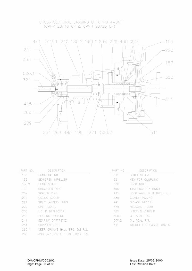
IOM/CPHM/0002/02 Issue Date: 25/09/2000 Page: Page 30 of 35 Last Revision Date:
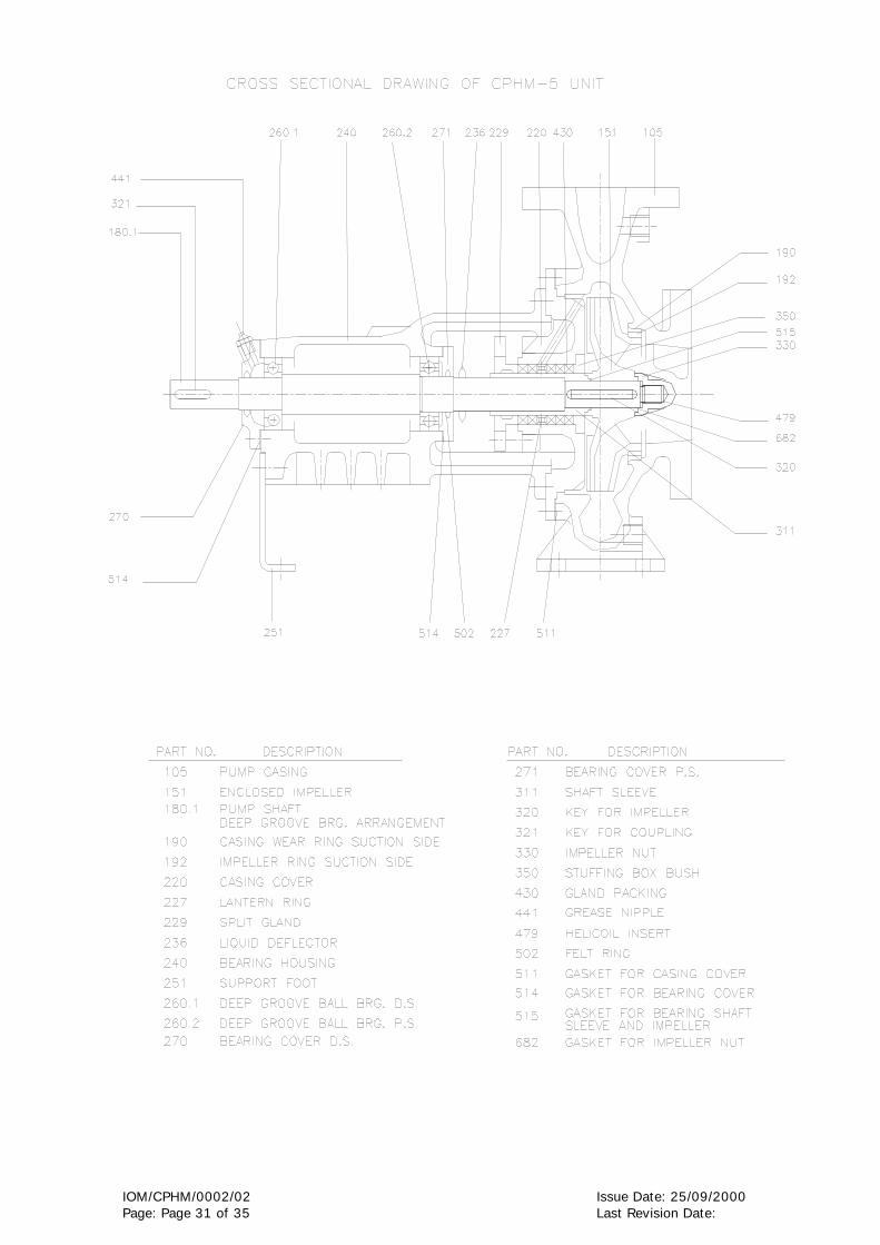
IOM/CPHM/0002/02 Issue Date: 25/09/2000 Page: Page 31 of 35 Last Revision Date:
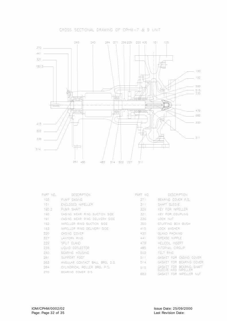
IOM/CPHM/0002/02 Issue Date: 25/09/2000 Page: Page 32 of 35 Last Revision Date:

GENERAL INFORMATION & SAFETY INSTRUCTIONS
1. The products supplied by KBL have been designed with safety in mind. Where
hazards cannot be eliminated, the risk has been minimized by the use of guards and
other design features. Some hazards cannot be guarded against and the instructions
below MUST BE COMPLIED WITH for safe operation. These instructions cannot cover
all circumstances. Installation, operation and maintenance personnel must use safe
working practices at all the times.
1.1 KBL products are designed for installation in designated areas, which are to be
kept clean and free of obstructions that may restrict safe access to the controls
and maintenance access points.
A pump duty nameplate is fitted to each unit and must not be removed. Loss of
this plate could make identification impossible. This in turn could affect safety
and cause difficulty in obtaining spare parts. If accidental loss or damage occur,
contact KBL immediately.
1.2 Access to the equipment should be restricted to the person net responsible for
installation, operation and maintenance and they must be trained, adequately
qualified and supplied with appropriate tools for their respective tasks.
1.3 Most accidents involving product operation, maintenance and repair are caused by
failure to observe safety rules or precautions. An accident can often be avoided
by recognizing potentially situations before an accident occurs. A person must be
aware of potential hazard associated in activities of installation, operation and
maintenance of equipments.
1.4 KBL requires that, all personnel that are responsible for installation, operation or
maintenance of the equipment, have access to and study the product instruction
manual BEFORE any work is done and that they will comply with all local and
industry based safety instructions and regulations.

1.5 Ear defenders should be worn where the specified equipment noise level exceeds
locally defined safe levels. Safety glasses or goggles or face shield should be
worn where working with pressurized systems and hazardous substances. Other
personal protection equipment must be worn where local rules apply. Wear safety
shoes, helmets and cotton overall [Apron] when you enter pump house. Noise
level should not exceed 90 dbA and 110 dbA for motor driven and engine driven
pumps, respectively.
1.6 Do not wear loose clothing or jewelry, which could catch on the controls or
become trapped in the equipment.
1.7 Read the instruction manual before installation, operation or maintenance of the
equipment. Check and confirm that you are referring relevant copy of the manual
by comparing pump type on the nameplate and with that on the manual.
1.8 Note the “Limits of product application permissible use” specified in the manual.
Operation of the equipment beyond these limits will increase the risk from hazards
noted below and may lead to premature and hazardous pump failure.
1.9 Clear and easy access to all controls, gauges and dials etc must be maintained at
all times. Hazardous or flammable materials must not be stored in pump rooms
unless safe areas or racking and suitable container have been provided.
1.10 Use suitable earthing and tripping devices for electrical equipments.
2. IMPROPER INSTALLATION, OPERATION, MAINTENANCE, LUBRICATION, REPAIR
OF THIS KBL PRODUCT COULD RESULT IN INJURY OR DEATH.
If any tool, procedure, work method and operation technique is not recommended
by KIRLOSKAR BROTHERS LIMITED is used or followed, it should be ensured that
it is a safe for personnel around and others. It should also be ensured that the
product will not be damaged or made unsafe by the operation, lubrication and
maintenance or repair procedures you choose.

3. SAFETY INSTRUCTIONS WHILE HANDLING AND STORAGE
When lifting the pump, use the lifting points specified on general arrangement
drawing, if provided. Use lifting equipment having a safe working load rating suitable
for the weight specified. Use suitable slings for lifting pump, which is not provided,
with lifting points. The use of forklift truck and chain crane sling equipment is
recommended but locally approved equipment of suitable rating may be used. While
lifting, the equipment adjusts the center of gravity, so that it is balanced properly.
Do not place fingers or hands etc into the suction or discharge pipe outlets and do
not touch the impeller, if rotated this may cause severe injury. To prevent ingress of
any objects, retain the protection covers or packaging in place until removal is
necessary for installation. If the packaging or suction and discharge covers are
removed for inspection purposes, replace afterwards to protect the pump and
maintain safety.
4. SAFETY INSTRUCTIONS WHILE ASSEMBLY & INSTALLATION
Shaft alignment must be checked again after the final positioning of the pump unit
and connection to pipework as this may have disturbed the pump or motor mounting
positions. If hot liquids [above 80°C] are being pumped, alignment should be checked
and reset with the pump and motor at their normal operating temperature. If this is
not possible, KBL can supply estimated initial offset figures to suit extreme operating
temperatures.
Failure to support suction and delivery pipework may result in distortion of the pump
casing, with the possibility of early pump failure.
5. SAFETY INSTRUCTIONS WHILE COMMISSIONING & OPERATION
Never attempt adjustments while the pump is running, unless otherwise specified in
the operation, maintenance manual.

Do not touch any moving or rotating parts. Guards are provided to prevent access to
these parts, where they have been removed for maintenance they must be replaced
before operating the equipment.
Check that pump is primed. Pump should never be run dry as the pumped liquid acts
as lubricant for the close running fits surrounding impeller and damage will be
incurred.
Failure to supply the stuffing box or mechanical seal with cooling of flush water may
result in damage and premature failure of the pump.
Do not touch surfaces, which during normal running will be sufficiently hot to cause
injury. Note that these surfaces remain hot after the pump has stopped, allow
sufficient time for cooling before maintenance. Be cautious and note that other parts
of the pump may become hot if a fault is developing.
Do not operate water pumps in temperatures below freezing point, without first
checking that the pumped fluid is not frozen and the pump is free to turn. Pumps in
these environments should be drained down during inactivity and re-primed before
starting.
In addition to local or site regulations for noise protection, KBL recommend the use of
personal ear protection equipment in all enclosed pump rooms and particularly those
containing diesel engines. Care must be taken to ensure that any audible alarm or
warning signal can be heard with car defenders worn.
Be aware of the hazards relating to the pump fluid, especially the danger from
inhalation of noxious and toxic gases, skin and eye contact or penetration. Obtain
and understand the hazardous substance data sheets relating to the pumped fluid and
note the recommended emergency and first aid procedures.

6. SAFETY INSTRUCTIONS WHILE MAINTENANCE & SERVICING
Do not attempt repairs of the pump or its accessories which you do not know. Use
proper tools.
Before attempting any maintenance on a pump particularly if it has been handling any
form of hazardous liquid, it should be ensured that the unit is safe to work on. The
pump must be flushed thoroughly with suitable cleaner to purge away any of the
product left in the pump components.
This should be carried out by the plant operator and a certificate of cleanliness
obtained before starting work. To avoid any risk to health it is also advisable to wear
protective clothing as recommended by the site safety officer especially when
removing old packing, which may be contaminated.
Isolate the equipment before any maintenance work is done. Switch off the main
supply, remove fuses, apply lockouts where applicable and affix suitable isolation
warning signs to prevent inadvertent reconnection. In order to avoid the possibility of
maintenance personnel inhaling dangerous fumes or vapours locations by removal of
bearing housing and shaft assembly to a suitable maintenance area.
Check and ensure that the pump operates at below the maximum working pressure
specified in the manual or on the pump namepate and before maintenance, ensure
that the pump is drained down.
Wear a suitable mask or respirator when working with packing and gasket contain
fibrous material, as these can be hazardous when the fibrous dust is inhaled. Be
cautious, if other supplier’s components have been substituted for genuine KBL parts,
these may then contain hazardous materials.
Store all oily rags or other flammable material in a protective container in a safe
place. Do not weld or flame cut on pipes/tubes that contents flammable fluids. Clean
them thoroughly with nonflammable solvent before welding or flame cutting on them.
Use solvent/chemical resistant gloves for hand protection.

Dispose of all wastes like gaskets, gland packing, oil, batteries, packing material etc
in accordance with local regulations. Normally this would involve incineration of liquid
waste and controlled landfill of polymerized material.
Adequacy of suitable crane should be checked before lifting the pump/pump
components. Also condition of pulleys, chain and lifting shackles should be checked
before use.
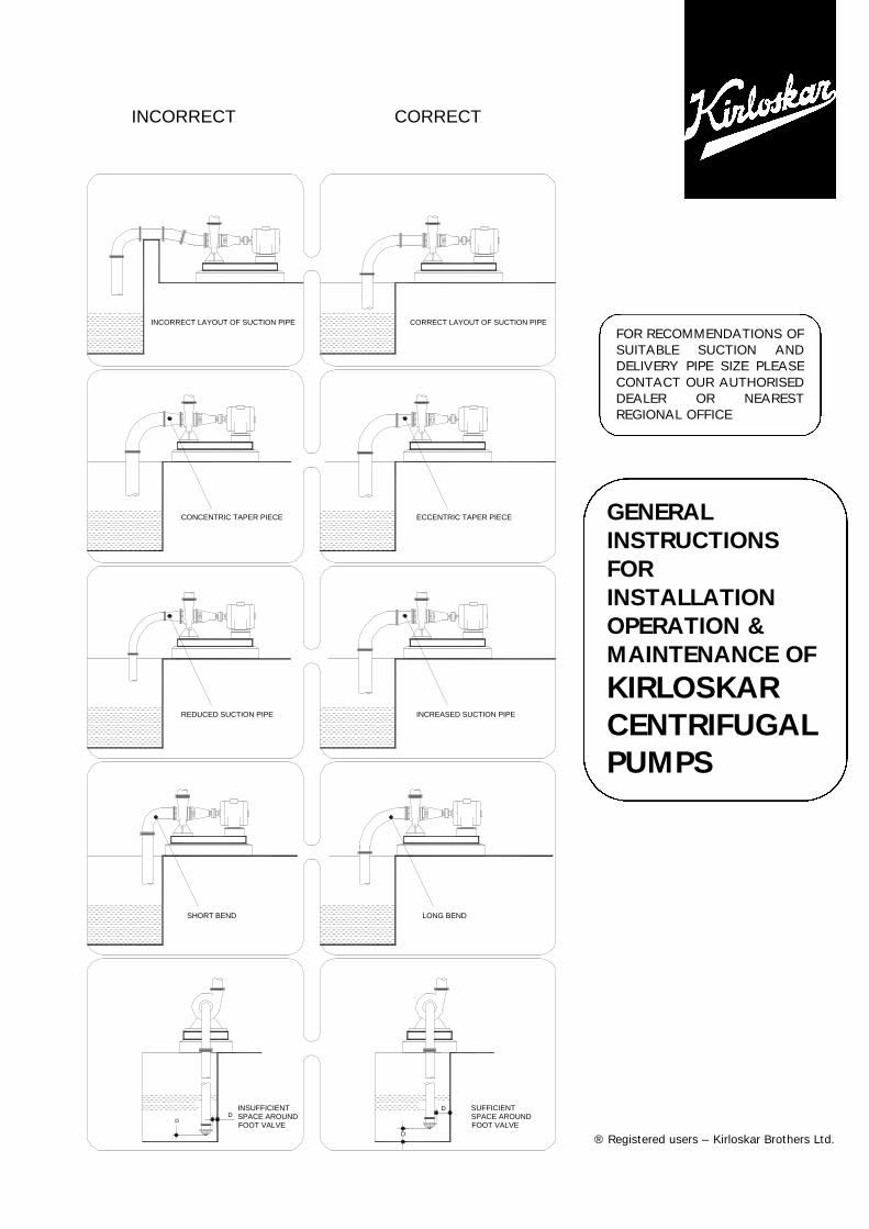
INCORRECT CORRECT
DD
SPACE AROUNDFOOT VALVE
INSUFFICIENT
SHORT BEND
REDUCED SUCTION PIPE
D
D SUFFICIENT
FOOT VALVESPACE AROUND
LONG BEND
INCREASED SUCTION PIPE
CONCENTRIC TAPER PIECE
INCORRECT LAYOUT OF SUCTION PIPE
ECCENTRIC TAPER PIECE
CORRECT LAYOUT OF SUCTION PIPE
FOR RECOMMENDATIONS OF SUITABLE SUCTION AND DELIVERY PIPE SIZE PLEASE CONTACT OUR AUTHORISED DEALER OR NEAREST REGIONAL OFFICE
GENERAL INSTRUCTIONS FOR INSTALLATION OPERATION & MAINTENANCE OF
KIRLOSKAR CENTRIFUGAL PUMPS
® Registered users – Kirloskar Brothers Ltd.

GENERAL INSTRUCTIONS FOR INSTALLATION, OPERATION & MAINTENANCE OF KIRLOSKAR CENTRIFUGAL PUMPS WARNING The equipment supplied is designed for specific capacity, speed, pressure and temperature. Do not use the equipment beyond the capacities for which it is manufactured. The equipment manufactured is also shop tested for the satisfactory performance and if it is operated is excess of the conditions for which it is manufactured, the equipment will be subject to excessive stresses and strains. LOCATION The pump should be located as near the liquid source as possible. This will minimise the suction lift and pump will give better performance. Ample space should be provided on all sides so that the pump can be inspected while in operation and can be serviced conveniently whenever required. FOUNDATION The foundation should be sufficiently substantial to absorb any vibration and to form a permanent rigid support for the base plate. This is important in maintaining the alignment of a direct connected unit. A concrete foundation on a solid base is advisable. Foundation bolts of the proper size should be embedded in the concrete located by a drawing or template. A pipe sleeve about two and one-half diameter larger that the bolt should be used to allow movement for the final position of the foundation bolts. ALIGNMENT Pumps and drivers that are supplied by the manufacturers, mounted on a common base plate are accurately aligned before despatch. However as the alignments are likely to be disturbed during transit to some extent and therefore must not be relied upon to maintain the factory alignment. Re-alignment is necessary after the complete unit has been levelled on the foundation and again after the grout has been set and foundation bolts have been tightened. The alignment must be checked after the unit is piped up and re-checked periodically. FLEXIBLE COUPLING A flexible coupling will not compensate for misalignment of the pump and driver shafts. The purpose of the flexible coupling is to compensate for temperature changes and to permit the movement of the shafts without interference with each other while transmitting power from the driver to the pump. TYPE OF MISALIGNMENT (SEE FIGURE 1) There are two types of misalignment between the pump shaft and the driver shaft.
(a) Angular misalignment : Shafts with axis concentric but not parallel. (b) Parallel misalignment : Shafts with axis Parallel but not concentric.
LEVELLING THE UNIT When the unit is received with the pump and driver mounted on the base plate, it should be placed on the foundation and the coupling halves disconnected. The coupling should not be reconnected until all alignment operations have been completed. The base plate must be supported evenly on wedges inserted under the four corners so that it will not be distorted or sprung by the uneven distribution of the weight. Adjust the wedges until the shafts of the pump and driver are in level. Check the coupling faces, suction and discharge flanges for the horizontal or vertical position by means of spirit level. FLEXIBLE COUPLING ALIGNMENT (SEE FIGURE2) The two halves of the coupling should be at least 4 mm apart so that they cannot touch each other when the driver shaft is rotated. Necessary tools for approximately checking are straight-edge and on an outside caliper.
Figure 1
PARALLEL MISALIGNMENTANGULAR MISALIGNMENT

4 Line supplying the
2 Vacuum equalizing line1 Tank under Vacuum
4
5
6 Connecting line
seeling liquid5 Valve
7 Valve
3 Valve
7
6
3
2
1
A check for parallel alignment is made by placing a straight-edge across both coupling periphery at the top, bottom and both the sides. The unit will be in parallel alignment when the straight-edge rests evenly on the coupling periphery at all positions. Care must be taken to have the straight-edge parallel to the axis of the shafts. A check for angular alignment is made by using an outside caliper across the width of the coupling faces at various points. Coupling alignment can be checked with dial gauge indicator as shown in Fig. 2. GROUTING When the alignment is correct, the foundation bolts should be tightened evenly but not too firmly. The unit can then be grouted by working soft concrete under the edges. Foundation bolts should not be fully tightened until the grout is hardened, usually 48 hours after poring. FACTORS THAT MAY DISTURB ALIGNMENT The unit should be periodically checked for alignment. If the unit does not stay in line after being properly installed, the following are possible causes:
(a) Setting, seasoning of the foundation (b) Pipe strains distorting of shifting the machines (c) Wear of the bearings
PIPING Both suction and delivery pipes and accessories should be independently supported near the pump so that when the flanges bolts are tightened no strain will be transmitted to the pump casing. It is usually advisable to increase the size of both suction and delivery pipes at the pump nozzles in order to decrease the loss of head from friction and for the same reason piping should be arranged with as minimum bends as possible, as these should be made with along radius wherever possible. The pipe lines should be free from scales, welding residuals etc., and have to be mounted in such a way that they can be connected to suction and delivery flanges without any stress on the pump. Adequate supports should be given to pipe lines to that weight of the pipe lines does not fall on the pump. The use of minimum number of the bends and other fittings will minimise the frictional losses. SUCTION PIPE The suction pipe should be as short as possible. This can be achieved by placing the pump near the liquid to be pumped. The suction pipe must be kept free from air leaks. This is particularly important when the suction lift is high. A horizontal suction line must have a gradual rise to the pump. Any high point in the pipe will be filled with air and thus prevent proper operation of the pump. A concentric taper piece should not be used in a horizontal suction line as it forms an air pocket in the top of the reducer and the pipe. Use an eccentric piece instead. The end of the suction pipe must be well submerged to avoid whirlpools and ingress of air but must be kept clear of nay deposits of mud, silt, grit etc. The pipe must be clear from any side of wall by at least 450 mm. The end of the suction pipe should be provided with a strainer of sufficient open area. DELIVERY PIPE A check (non-return) valve and a gate of sluice valve (regulating valve) should be installed in the discharge line. The check valve placed between the pump and the gate valve is to protect the pump from excessive pressure and to prevent water running back through the pump in case of failure of the driving machine. Discharge piping should be provided with a sluice valve adjacent to the delivery flange to control the discharge, if required. VACUUM EQUALISING LINE (AND LIQUID LINE) (SEE FIGURE 3) If the pump draws from a system under vacuum an equalising pipe must be carried from the highest point of the suction line, however, as close to the suction flange of the pump as possible, to the top of the feed tank to keep gas bubbles that might have been entrapped in the flow from entering the pump. The line should be fitted with an isolating valve which should be closed only for maintenance work on the pumpset. Apply sealing liquid (external sealing) to the shaft seal cage to prevent entry of air in the case of pumps with packed stuffing box. It is convenient to tap the sealing liquid from the delivery line above the non-return valve.
STRAIGHT EDGE
Figure 2
MEASURINGWEDGE

FOOT VALVE It is advisable to install a foot valve to facilitate priming. The foot valve should have sufficient clear passage for water. Care must be taken to prevent foreign matter from being drawn into the pump or choking the foot valve and for this purpose an efficient strainer should be provided. STUFFING BOXES AND PACKING Stuffing boxes should be carefully cleaned and the packing placed in them. Be sure that sufficient packing is placed at the back of the water seal cage. If the water to be pumped is dirty or gritty, sealing water should be piped to the stuffing boxes from clean outside source of supply in order to prevent damage to the packing and shaft. In placing the packing, each packing ring should be cut to the proper length so that ends come together but do not overlap. The succeeding rings of packing should not be pressed too tight as it may result in burning the packing and cutting the shaft. If stuffing box is not properly packed, friction in stuffing box prevents turning the rotor by hand. On starting the pump it is well to have the packing slightly loose without causing an air leak, and if it seems to leak, instead of putting too much pressure on the gland, put some heavy oil in the stuffing box until the pump works properly and then gradually tighten up the gland. The packing should be occasionally changed. BALL BEARINGS Correct maintenance of ball bearings is essential. The bearing manufacturers give the following as a guide to relubrication periods under normal conditions. Three monthly when on continuous duty. Six monthly when on eight-hour per duty. The bearings and housings should be completely cleaned and recharged with fresh grease after 2500 hours or the nearest pump overhaul time. PRIMING No pumping action occurs unless the pump casing is filled with liquid. Pump casing and suction pipe must therefore be completely filled with the liquid and thus all air removed before the pump is started. Several different priming methods can be used depending on the kind of installation and service involved. (1) Liquid level above pump level Pump is set below liquid level of source of supply so that liquid always flows to pump under positive
head. (2) Priming with foot valve
(a) When pump is installed on suction lift with foot valve at the end of suction line, fill pump with water from some outside source till all air is expelled and water flows through air vent.
(b) When there is liquid under some pressure in the discharge pipe, priming can be effected by byepassing the pressure liquid around the check and gate valve. Of course, the initial priming must be effected from some outside source. NOTE: in this case, the foot valve must be capable of withstanding pump pressure and possible surge.
(3) Priming by ejector: An ejector operated by steam, compressed air or water under pressure and connected to air vent on top of casing can be used to remove air from and prime the pump on suction lift installations.
(4) Priming by dry vacuum pump : a hand or power pump sucks in all the air from the casing and the suction pipe, and thus primes the system.
STARTING The pump must not be started without being primed. Be sure that the driver rotates in the proper direction as indicated by a direction arrow on the pump casing. RUNNING On account of its simple construction, the centrifugal pump requires practically no attention while running. Lubrication of the bearings and manipulation of the glands are the only things that need attention from the operator. STOPPING Before stopping the pump, close the gate valve. This will prevent water hammer on check valve. STUFFING BOXES Do not tighten the glands excessively. A slight dripping of water from the stuffing boxes when pump is running keeps packing in good condition. CASING RINGS Casing rings are fitted in the casing to reduce the quantity of water leaking back from the high pressure side to the suction side. These casing rings are fitted to maintain a small clearance and depend on the water in the pump for lubrication. When they are worn out, the clearance becomes greater and more water passes back into the suction. They must be replaced from time to time to restore the pump efficiency to its normal value.

SPARE PARTS A set of ball bearings, a set of casing rings, and a set of gland packing rings must always be kept at hand to ensure uninterrupted service from the pump. While ordering for spare parts, always give type, size and serial number of the pumps as stamped on the name plate. PUMP TROUBLE When investigating trouble with Kirloskar pumps, always remember that pumps have been tested at the factory and are mechanically correct when sent out. Discounting the possibility of damage during transit, most of the trouble in the field is due to faulty installation. Investigation shows that the majority of troubles with centrifugal pumps result from faulty conditions on the suction side. BREAK DOWN-CAUSE-CHECK POINTS In case of breakdown we recommend the location of the fault by using the following table.
BREAKDOWN CHECK POINTS
Pump does not deliver 1 7 8 9 10 11 12 14 15 17 18 19 23 25 26 56 57 58
Pump delivers at reduced capacity 1 2 3 4 5 6 7 8 9 10 11 12 13 14 15 17 18 19 20 21 22 56 57 58
Delivery performance deteriorates 1 3 7 9 10 11 12 13 14 19 20 21 22 23 24 53 57 62
Pump delivers too much 16 56 57 58
Delivery is interrupted 1 3 6 7 8 9 10 11 12 13 14 15 16 19 22 23 25 26 56 57 58 62
After stopping pump runs in reverse direction 52
Very noisy 1 2 5 6 7 8 11 12 13 15 19 20 22 54 55 56 57 62
Unsteady running of pump 19 20 22 31 32 33 35 36 37 38 39 40 43 44 47 48 49 50 51 54 55 58
Stuffing box leaks excessively 24 27 28 29 30 31 47 48 49 53
Fumes from stuffing box 22 23 24 25 26 27 28 29 30 41 42 43
Pump rotor locked in standstill position 22 45 46 50
Pump is heating up and seizing 23 24 25 26 27 28 29 30 40 41 42 45 47 48 49 50 54
Bearing temperature increases 19 20 21 22 31 32 33 34 35 36 37 38 39 40 41 42 43 44 45 46 47 48 49 51 54 55 58
Motor will not start 14 22 60
Motor gets hot or burns out 14 22 27 28 40 43 50 55 56 57 58 59 60 61
Motor is difficult to start 14 22 27 28 45 46 50 58 59 60

CHECK POINTS
1. Suction pipe, foot valve choked. 2. Nominal diameter of suction line too small. 3. Suction pipe not sufficiently submerged. 4. Too many bends in the suction line. 5. Clearance around suction inlet not sufficient. 6. Shut off valve in the suction line in
unfavourable position. 7. Incorrect layout of suction line (formation of air
pockets). 8. Valve in the suction line not fully open. 9. Joints in the suction line not leak-proof. 10. Air leaking through the suction line and stuffing
box etc. 11. Suction lift too high. 12. Suction head too low (difference between
pressure at suction connection and vapour pressure too low).
13. Delivery liquid contains too much gas and/or air.
14. Delivery liquid too viscous. 15. Insufficient venting. 16. Number of revolutions too high. 17. Number of revolutions too low. 18. Incorrect direction of rotation (electric motor
incorrectly connected, leads of phases on the terminal block interchanged).
19. Impeller clogged. 20. Impeller damaged. 21. Casing rings worn out. 22. Separation of crystals from the flow of
pumping liquid (falling below the temperature limit/equilibrium temp).
23. Sealing liquid line obstructed. 24. Sealing liquid contaminated. 25. Lantern ring in the stuffing box is not
positioned below the sealing liquid inlet. 26. Sealing liquid omitted. 27. Packing incorrectly fitted. 28. Gland tightened too much/slanted.
29. Packing not suitable for operating conditions. 30. Shaft sleeve worn in the region of the packing. 31. Bearing worn out. 32. Specified oil level not maintained. 33. Insufficient lubrication of bearings. 34. Ball bearings over-lubricated. 35. Oil/Grease quality unsuitable. 36. Ball bearing incorrectly fitted. 37. Axial stress on ball bearings (no axial clearance
for rotor). 38. Bearings dirty. 39. Bearings rusty (corroded). 40. Axial thrust too great because of worn casing
rings, relief holes obstructed. 41. Insufficient cooling water supply to stuffing box
cooling. 42. Sediment in the cooling water chamber of the
stuffing box cooling. 43. Alignment of coupling faulty or coupling loose. 44. Elastic element of coupling worn. 45. Pump casing under stress. 46. Pipeline under stress. 47. Shaft runs untrue. 48. Shaft bent. 49. Rotor parts insufficiently balanced. 50. Rotor parts touching the casing. 51. Vibration of pipe work. 52. Non-return valve gets caught. 53. Contaminated delivery liquid. 54. Obstruction in delivery line. 55. Delivery flow too great. 56. Pump unsuitable for parallel operation. 57. Type of pump unsuitable. 58. Incorrect choice of pump for existing operating
conditions. 59. Voltage too low/power supply overloaded. 60. Short circuit in the motor. 61. Setting of starter of motor too high. 62. Temperature delivery liquid too high.