
UG03-2035E en RXIG 21 28 Instantaneous of Definite-time Ac Overcurrent Relay Assemblies Users Guide

GEK-49826D
INSTANTANEOUS OVERCURRENT RELAYS
TYPES:
INSTRUCTIONS
HFC21B, HFC22B, HFC23C
GE Protection and Control205 Great Valley ParkwayMalvern, PA 19355-1337
GEK-49826
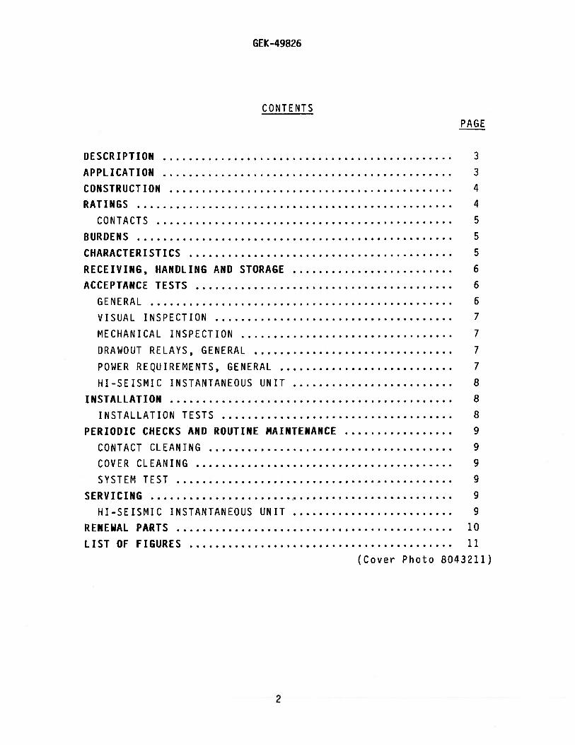
CONTENTS
PAGE
DESCRIPTION
APPLICATION
CONSTRUCTION
RATINGS
CONTACTS
BURDENS
CHARACTERISTICS
RECEIVING, HANDLING AND STORAGE
ACCEPTANCE TESTS
GENERAL
VISUAL INSPECTION
MECHANICAL INSPECTION
DRAWOUT RELAYS, GENERAL
POWER REQUIREMENTS, GENERAL
HI—SEISMIC INSTANTANEOUS UNIT
INSTALLATION
INSTALLATION TESTS
PERIODIC CHECKS AND ROUTINE MAINTENANCE
CONTACT CLEANING
COVER CLEANING
SYSTEM TEST
SERVICING
HI-SEISMIC INSTANTANEOUS UNIT
RENEWAL PARTS
LIST OF FIGURES
334455566677778889999991011
(Cover Photo 8043211)
2
GEK-49826
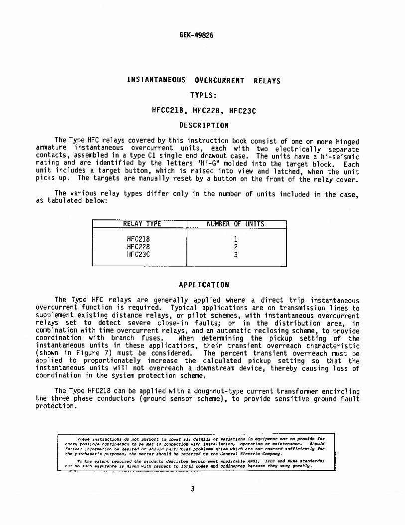
INSTANTANEOUS OVERCLJRRENT RELAYS
TYPES:
HFCC21B, HFC22B, HFC23C
DESCR IPTION
The Type HFC relays covered by this instruction book consist of one or more hingedarmature instantaneous overcurrent units, each with two electrically separatecontacts, assembled in a type Cl single end drawout case. The units have a hi—seismicrating and are identified by the letters “Hi—G” molded into the target block. Eachunit includes a target button, which is raised into view and latched, when the unitpicks up. The targets are manually reset by a button on the front of the relay cover.
The various relay types differ only in the number of units included in the case,as tabulated below:
RELAY TYPE NUMBER OF UNITS
HFC21B 1HFC22B 2HFC23C 3
APPLICATION
The Type HFC relays are generally applied where a direct trip instantaneousovercurrent function is required. Typical applications are on transmission lines tosupplement existing distance relays, or pilot schemes, with instantaneous overcurrentrelays set to detect severe close—in faults; or in the distribution area, incombination with time overcurrent relays, and an automatic reclosing scheme, to providecoordination with branch fuses. When determining the pickup setting of theinstantaneous units in these applications, their transient overreach characteristic(shown in Figure 7) must be considered. The percent transient overreach must beapplied to proportionately increase the calculated pickup setting so that theinstantaneous units will not overreach a downstream device, thereby causing loss ofcoordination in the system protection scheme.
The Type HFC21B can be applied with a doughnut—type current transformer encirclingthe three phase conductors (ground sensor scheme), to provide sensitive ground faultprotection.
These instructions do not purport to cover all details or variations in equipment nor to provia’e for
ec,ri possible continyoncy to be met in Connection with Installation, operation or maintenance. Shouldfurtner informato.i be des:reci or should particular proble,rm arise which are not covered sufficiently forthe purchasers purposes, the matter should be referred to the General Electric Company.
To the pxret required the jrducts described heroin meet applicable ANSi, IEEA’ and NEMA standards:!jt no such assurance is given wth respect to local codes and ordinances because they vary greatly.
3
GEK-49826
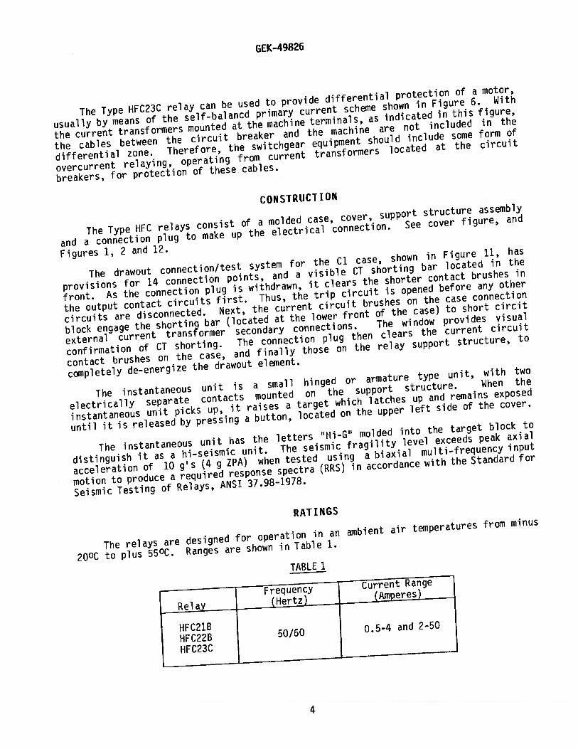
The Type HFC23C relay can be used to provide differential protection of a motor,
usually by means of the self-balancd primary current scheme shown in Figure 6. With
the current transformers mounted at the machine terminals, as indicated in this figure,
the cables between the circuit breaker arid the machine are not included in the
differential zone. Therefore, the switchgear equipment should include some form of
overcurrent relaying, operating from current transformers located at the circuit
breakers, for protection of these cables.
CONSTRUCTION
The Type HFC relays consist of a molded case, cover, support structure assembly
and a connection plug to make up the electrical connection. See cover figure, and
Figures 1, 2 and 12.
The drawout connection/test system for the Cl case, shown in Figure 11, has
provisions for 14 connection points, and a visible CT shorting bar located in the
front. As the connection plug is withdrawn, it clears the shorter contact brushes in
the output contact circuits first. Thus, the trip circuit is opened before any other
circuits are disconnected. Next, the current circuit brushes on the case connection
block engage the shortin9 bar (located at the lower front of the case) to short circit
external current transformer secondary connections. The window provides visual
confirmation of CT shorting. The connection plug then clears the current circuit
contact brushes on the case, and finally those on the relay support structure, to
completely de-energize the drawout element.
The instantaneous unit is a small hinged or armature type unit, with two
electrically separate contacts mounted on the support structure. When the
instantaneous unit picks up, it raises a target which latches up and remains exposed
until it is released by pressing a button, located on the upper left side of the cover.
The instantaneous unit has the letters “Hi-G” molded into the target block to
distinguish it as a hi-seismic unit. The seismic fragility level exceeds peak axial
acceleration of 10 g’s (4 g ZPA) when tested using a biaxial multi-frequency input
motion to produce a required response spectra (RRS) in accordance with the Standard for
Seismic Testing of Relays, ANSI 37.98—1978.
RATINGS
The relays are designed for operation in an ambient air temperatures from minus
200C to plus 55°C. Ranges are shown in Table 1.
TABLE 1
Frequency Current Range
Relay (Hertz) (Amperes)
HFC21BHFC22B 50/60 0.5-4 and 2-50
HFC23C
4

GEK-49826
The instantaneous units have a tapped coil for operation on either one or tworanges, HIGH (H) or LOW (L). Selection of the HIGH or LOW range is determined by theposition of the link located on the top of the support structure (see Figure 1 andTable 2).
TABLE 2
Hi-Seismic Continuous ***Qne SecondInstantaneous Link **Range Rating RatingUnit (Amps) Position (Amps) (Amps) (Amps) K
L 0.5 - 2 0.750.5 - 4 94 8,836
H 2 - 4 1.5
L 2 -10 3.72 - 50 130 16,900
H 10 -50 7.5
**The range is approximate, which means that the 2—10 amp range may be 2-8amps, and the 10—50 amp range may be 8-50 amps. There will always be at leastone ampere overlap between the maximum L setting and the minimum H setting.Always select the higher range whenever possible, since it has a highercontinuous rating.
***Higher currents may be applied for shorter lengths of time in accordance withthe formula:
CONTACTS
The contacts will carry 30 amperes trip current.
BURDENS
The hi—seismic instantaneous unit burdens are listed in Table 3.
CHARACTERISTICS
The instantaneous units have either a 25 to 1 or an 8 to 1 range with a tappedcoil. There are high and low ranges, selected by means of links located on the top ofthe support structure (see Figure 1). The time current curve for the instantaneousunits is shown in Figure 8.
5

GEK—4 9826
Hi-Seismic —
Minimum Burden at Minimum urden in Ohms (Z
Inst. Unit Link Range Pickup Pickup_(Ohms) Times_Pickup
(Amps) Hz Position (Amps) (Amps) R Z 3 10 20
0.5—4 60L 0.5 - 2 0.5 10.63 9.77 14.44 9.81 8.56 7.80
H 2 - 4 2 5.13 3.49 6.21 4.66 4.26 4.18
L 2 - 10 2 0.750 0.650 0.992 0.634 0.480 0.457
2-50 60 H 10 - 50 10 0.070 0.024 0.074 0.072 0.071 0.070
L 0.5 - 2 0.5 8.86 8.14 12.03 8.18 7.13 6.50
0.5-4 50 H 2 - 4 2 4.28 2.91 5.18 3.88 3.55 3.48
L 2 - 10 2 0.625 0.542 0.827 0.528 0.400 0.380
2-50 50 H 10 - 50 10 0.058 0.020 0.062 0.060 0.059 0.058
RECEIViNG, HANDLING AND STORAGE
These relays, when not included as part of a control panel will be shipped in
designed to protect them against damage. Immediately upon receipt of a relay,
it for any damage sustained in transit. If damage resulting from rough
is evident, file a damage claim at once with the transportation company and
notify the nearest General Electric Apparatus Sales Office.
Reasonable care should be exercised in unpacking the relay in order that none of
the parts are damaged or the adjustments disturbed.
If the relays are not to
original cartons in a place
Foreign matter collected on
cover is removed, and cause
be installed immediately, they should be stored in their
that is free from moisture, dust and metallic chips.
the outside of the case may find its way inside when the
trouble in the operation of the relay.
ACCEPTANCE TESTS
GENERAL
The relay should be examined and tested upon delivery to ensure that no damage has
been sustained in shipment and that the relay calibrations have not been disturbed. If
examination or test indicates that a readjustment is necessary, refer to the section on
SERVICING.
TABLE 3
cartonsexaminehandlingpromptly
6

GEK-49826
The following tests may be performed as part of the installation of the relay atthe discretion of the user. Since most operating companies use different proceduresfor acceptance and installation tests, the following section includes all applicabletests that may be performed on Ihe relays.
VISUAL INSPECTION
Check the nameplate stamping to ensure that the model number and rating of therelay agree with the requisition.
Remove the relay from its case and check that there are no broken or crackedmolded parts or other signs of physical damage, and that all the screws are tight.
MECHANICAL INSPECTION
1. The armature and contacts of the instantaneous unit should move freely whenoperated by hand. There should be at least 1/64—inch wipe on the instantaneouscontacts.
2. The target in the instantaneous unit must come into view and latch when thearmature is operated by hand, and should unlatch when the target release button isoperated.
3. Make sure that the brushes and shorting bars agree with the internal connectionsdi a gram.
CAUTION: If there is a need to tighten any screws, DO NOT OVERTIGHTEN. Overtighteningmay cause stripping.
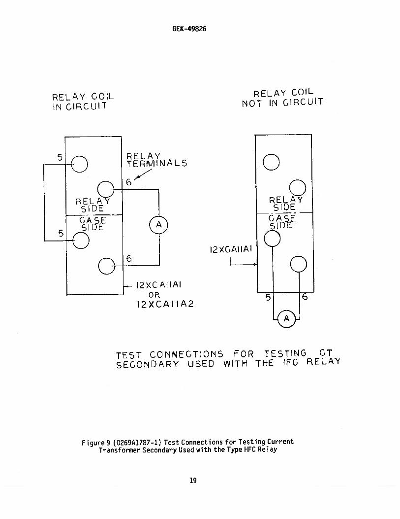
DRAWOUT RELAYS, GENERAL
The HFC relays may be tested without removing them from the panel by using the12XCA11A1 four-point test probes. These test probes make connections to both the relayand the external circuitry, which provides maximum flexibility, but requiresreasonable care in use, since a CT shorting jumper is necessary when testing. The CTcircuit may also be tested by using an ammeter with the 12XCA11A2. See the test circuitof Figure 9.
NOTE: Figure 9 shows test connections for the HFC21B current transformer, and theleft unit current transformer of the HFC22B and HFC23C. To test the CTs ofthe HFC22B and HFC23C, refer to internal connections shown in Figures 4 and5, respectively.
POWER REQUIREMENTS, GENERAL
All alternating current operated devices are affected by frequency. Since non—sinusoidal waveforms can be analyzed as a fundamental frequency plus harmonics of thefundamental frequency, it follows that alternating current devices (relays) will beaffected by the applied waveform.
7

GEK-49826
Therefore, in order to properly test alternating current relays it is essential to
use a sine wave current and/or voltage. The purity of the sine wave (i.e., its freedom
from harmonics) cannot be expressed as a finite number for any particular relay;
however, any relay using tuned circuits, R-L or RC networks or saturating
electromagnets (such as time overcurrent relays), would be essentially affected by non
sinusoidal waveforms. Hence a resistance-limited circuit, as shown in Figure 10, is
recommended.
HI-SEISMIC INSTANTANEOUS UNIT
Make sure that the instantaneous unit link is in the correct position for the
range in which it is to operate. Use the higher range whenever possible, since the
higher range has a higher continuous rating. Test connections for testing pickup and
operating times are shown in Figure 10.
NOTE: Figure 10 shows test connections for the HFC21B and the left unit of the
HFC22B and HFC23C. To test the other units of the HFC22B and HFC23C, refer
to internal connections shown in Figures 4 and 5, respectively.
Setting the Hi-Seismic Instantaneous Unit
The instantaneous unit has an adjustable core located at the top of the unit as
shown in Figure 1. To set the instantaneous unit to a desired pickup, loosen the
locknut and adjust the core. Turning the core clockwise decreases the pickup; turning
it counterclockwise increases the pickup. Bring up the current slowly until the unit
picks up. It may be necessary to repeat this operation until the desired pickup value
is obtained. Once the desired pickup value is reached, tighten the locknut.
CAUTION: REFER TO TABLE 2 FOR THE CONTINUOUS AND ONE SECOND RATINGS OF THE
INSTANTANEOUS UNIT. DO NOT EXCEED THESE RATINGS WHEN APPLYING CURRENT TO THE
INSTANTANEOUS UNIT.
The range of the instantaneous unit (see Table 2) must be obtained between a core
position of one-eighth of a turn fully clockwise, and 20 turns counterclockwise from
the fully clockwise position. Do not leave the core in the fully clockwise position.
INSTALLATION
The relay should be installed in a location that is clean, dry, free from dust,
and well lighted to facilitate inspection and testing.
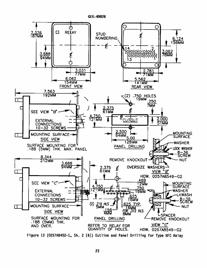
The relay should be mounted on a vertical surface. The outline and panel drilling
dimensions are shown in Figures 12 and 13. Figure 12 shows semi—flush mounting, and
Figure 13 shows various methods of surface mounting.
The internal connections diagrams for the relays are shown in Figures 3, 4 and 5.
INSTALLATION TESTS
The following tests are to be performed at the time of installation:
8

GEK-49826
Hi-Seismic Instantaneous Unit
1. Select the desired range by setting the link in the proper position (see
Figure 1 and the internal connections diagram). Always select the higher
range whenever possible, since it has a higher continuous rating.
2, Set the instantaneous unit to pick up at the desired current level. See
‘Setting the Instantaneous Unit11 in the ACCEPTANCE TESTS section.
All the tests described under INSTALLATION must be performed at the time of
installation. In addition, if those test described under the ACCEPTANCE TESTS section
were not performed prior to installation, it is recommended that they be performed at
this time.
PERIODIC CHECKS AND ROUTINE MAINTENANCE
In view of the vital role of protective relays in the operation of a power system,
it is important that a periodic test program be followed. The interval between
periodic checks will vary depending upon environment, type of relay and the user’s
experience with periodic testing. Until the user has accumulated enough experience to
select the test interval best suited to his individual requirements, it is suggested
that the points listed below be checked at an interval of from one to two years.
CONTACT CLEANING
A flexible burnishing tool should be used for cleaning relay contacts. This is a
flexible strip of metal with an etched-roughened surface, which in effect resembles a
superfine file. The polishing action of this file is so delicate that no scratches are
left on the contacts, yet it cleans off any corrosion thoroughly and rapidly. The
flexibility of the tool insures the cleaning of the actual points of contact. Do not
use knives, files, abrasive paper or cloth of any kind to clean relay contacts.
COVER CLEANING
The clear Lexarc cover should be cleaned with a soft cloth and water only. No
cleaning solutions should be used. Use of cleaning solutions other than water may
damage the clear cover.
SYSTEM TEST
Although this instruction book is intended primarily to check and set the HFC
relay, overall functional tests to check the system’s operation are recommended at
intervals based on the customer’s experience.
SERVICING
HI-SEISMIC INSTANTANEOUS UNIT
1. Both contacts should close at the same time.
®Registereci trademark of the General Electric Co.
9

GEK-49826
2. With the armature against the pole piece, there should be at least 1/64-
inch wipe on the contacts. Check this by inserting a 0.010 inch feeler
gage between the front half of the shaded pole with the armature held
closed. Contacts should close with the feeler gage in place. Since
mechanical adjustments may affect the seismic fragility level, It Is
advised that no mechanical adjustments be made If seismic capability is of
concern.
RENEWAL PARTS
Sufficient quantities of renewal parts should be kept in stock for the prompt
replacement of any that are worn, broken or damaged.
When ordering renewal parts, address the nearest Sales Office of the General
Electric Company. Specify the name of the part wanted, quantity required, and
complete nameplate data, Including the serial number, of the relay.
Since the last edition, Figures 12 and 13 have been changed.
10

GEK-49826
LIST OF FIGURES
FIGURE PAGE
1 Type HFC23B Relay Removed from Case, Front View 12
2 Type HFC23B Relay Removed from Case, Rear View 12
3 Internal Connections for Type HFC21BRelay, Front View 13
4 Internal Connections for Type HFC22BRelay, Front View 14
5 Internal Connections for Type HFC23CRelay, Front View 15
6 External Connections for Type HFC23C,Self-Balancing Primary CurrentDifferential Scheme for Motor Protection 16
7 Transient Overreach Characteristicsof the Hi—Seismic Instantaneous Unit 17
8 Time-Current Characteristicsof the Hi-Sesimic Instantaneous Unit 18
9 Test Connections for Testing CurrentTransformer Secondary Used with the HFC Relay 19
10 Test Connections for Testing Pickup andOperating Times of the Type HFC RelayHi-Seismic Instantaneous Unit 20
11 Cross Section of Type HFC Drawout CaseShowing Shorting Bar 21
12 Outline and Panel Drilling for Type HFC Relay 22
13 Outline and Panel Drilling for Type HFC Relay 23
11

GEK-49826
RANGE SELECTiONLINKS
iNSTANTANEOUSUNIT ADJUSTABLECORE
i—INSTANTANEOUSUNIT TARGET
Figure 1 (8043212) Type HFC23B Relay, Removed From Case, Front View
•—
INSTANTANEOUSUNIT ADJUSTABLECORE
‘—TARGET RESETMECHANISM
suorSTRUCTURE
Figure 2 (8043213) Type HFC23B Relay, Removed from Case, Rear View
LI KSRANGE SELEC
12

GEK-4g826
-it
INST SETTINGSET LINK TO”H”FCR HIGH RANGEAND 1O”L’’ FORLOW RANGE.LINK SHOWN INHIGH RANGEPOSIT JON.
INSTANTANEOUS INST.
1*O
*=SHORT FiNGERS
Figure 3 (0269A3074-O) Type HFC21B Internal Connections Diagram, Front View
13

GEK-49826
*SHORT FINGERS
Figure 4 (0275A1900-O) Type HFC22B Internal Connections Diagram, Front View
LEFTINST.
RIGHTINST.
BT
INS TA NTANEQIISUNITS
II RIGHT_HI
___
___
EFT
C)
3 5INST. SETTiNGS
SET LINK TO 4H’ FOR HIGH RANGE
AND TO “L” FOR LOW RANGE.
LINK SHOWN IN HIGH RANGE POSITION.
/
*
H
6 0
14

INSTANTANEOUSU N TS
GEK-49826
LEFTI N ST.
B
T
E
L H
MIDDLE RIGHTINSt INST.
I NSTANTAN EOUS SETTING S
SET LINK TO”H’ FOR HIGH RANGEAND TO”L’ FOR LOW RANGE.LINK SHOWN IN HiGH RANGE POSITION.
Figure 5 (0285A6295-O) Internal Connections for Relay Type HFC23C, Front View
H
H
H H
3 5
15

BUS
GEK—49826
2 3
LI &I187
87-HFC 23C52-CIRCUIT BREAKER
7
.—-
I9 10
4 If IIvi_
t_::’ *(4-)ALARM BUS
113N0TE I)
MOTOR f.Q2 2
2
TO ALARM
NOTE l:AS AN OPTION CONNECTING STUD 3
TO (+) ALARM BUS 4ILL PROVIDE AN ALARM
WHEN RELAY CONNECTION PLUG IS REMOVED.
DO NOT USE THIS KIND OF CONNECTION ON
THE TRIP CIRCUIT SINCE A FALSE TRIP
WOULD OCCUR.
Figure 6 (0285A7123-O) External Connections forTypeHFC23C, Self Balancing
Primary Current Differential Scheme for Motor Protection
C-f) TRIP BUS
4 (NOTE I)
( —)
16

H
GEK-49826
-J
w
1NJ3d Ni )VY3&13A0
Figure 7 (0208A8694—2) Transient Overreach CharacteristicsOf the Hi-Seismic Instantaneous Unit
17

Char8CttFigure8 (O2O8A8695’
Timer0tC 1nstaof the Hi _Seismi
18
GEK-49260
a)
a()
D
LL0(1)L)J
C)
U.)U)
cv)
8
GEK-498?6
RELA’ GOLIN CIRCUIT
RELAY COILNOT IN CIRCUIT
2XC AHAIOR
12XCAI 1A2
Figure 9 (0269A1787—1) Test Connections for Testing CurrentTransformer Secondary Used with the Type HFC Relay
RELAYTERMINALS 0
0RELAY51DE
CASESIDE
00
I2XGAIIAI
7
5 6
TEST CONNECTIONS FOR TESTING GTSECONDARY USED WITH THE fF0 RELAY
19

GEK- 49826
MINIMUMRECCMMEN DEDVOLTS, 120 ATRATED FREQ.
TO STOPTIMER
TO STARTTiMER
4\ 4\ TO INDICATING
r—tLIGHT WHEN[cHEcKING PICKUP
RELAYTERM INAL
VARIABLERESISTOR
I CT1< JUMPER
TEST CONNECTIONS FOR TESTING PICKUP AND
OPERATING TIMES OF THE HFC RELAY INSTAN
TANEOUS UNIT WITH ELECTRiCALLY SEPARATE
CONTACTS.
Figure 10 (0275A1904—O) Test Connections for Testing Pickup and
Operating Times of Type HFC Relay Hi-Seismic Instantaneous Unit
oio
7o
3 4 5 6
12XCAHA1—
6U
RE LAYSIDE
CASESiDE
0CASESIDE
0
U
URELAYSIDE
CASESIDE
C)
50
20

GEK-49826
CONTACT FINGERS
Figure 11(8042715) Cross-Section of Type HFC Relay Drawout CaseShowing Shorting Bar
CONNECTION PLUG
\ORAWOUT ELEMENTSUPPORT STRUCTURE
RELAY CASE / /SHORTING BAR CASE CONNECTION BLOCK
21

GEK-49826
PANELMAX .125 THK.
3MM
VIEW “An
HDW—O257A8549 C—i
# 10—32 SCREWTHREADCUTTING
1 REY
7.376187MM
F I --
3. 6894MM
-_
_
— cçUD NUMBERING
3.03177MM
6.062 —
154MMREAR VIEW
EXTERNALCONNECTIONS10—32 SCREWS
MOUNTING SURFACE
SIDE VIEWSEMI—FLUSH
WASHER
LOCKWASHERSCREW
NUT
TIE ANCHOR
CABLE TIEVIEW ““
Figure 12 (0257A8452-1, Sh. 1 [61) OutlIne and Panel Drilling for Type HFC Relay
CABLES
22
GEK-49826
EXTERNALCONNECTIONS10—32 SCREWS
SURFACE MOUNTING FOR.188 (5MM) THK.AND OVER.
VIEW “B”0257A8549 —G2
VIEW “C”HDW. 0257A8549—G2
STUDNUMBERING
——
7.563FRONT VIEW REAR VIEW
I
I 192MMLL
SEE VIEW “B”—\
EXTERNALCONN ECTIONS10—32 SCREWS—
EIE MOUNTING SURFACESIDE VIEW
SURFACE MOUNTING FOR.188 (5MM) THK. MAX. PANEL
PANEL DRILLING
REMOVE
IER
KNOCKOUT
SEE VIEW “C”\
NUT
HDW.
MOUNTING SURFACESIDE VIEW
(2) .219 HLS5MM156
4MM
MOUNTINGSURFACEWASHER
WASH
PANEL DRILLING
NUT
REFER TO RELAY FORQUANTITY OF HOLES.
SPACERREMOVE KNOCKOUT
Figure 13 (0257A8452—1, Sh. 2 [61) Outline and Panel Drilling for Type HFC Relay
23

GE Power Management
215 Anderson AvenueMarkham, OntarioCanada L6E 1B3Tel: (905) 294-6222Fax: (905) 201-2098www.ge.comlindsyslpm


![Securing Relay Networks with Artificial Noise: An Error ...the form of repeaters [35]. For the AF protocol, we make the common assumption that the destination has the instantaneous](https://static.fdocuments.in/doc/165x107/5e8d038c60bd96299c0ea067/securing-relay-networks-with-artificial-noise-an-error-the-form-of-repeaters.jpg)
