Instructions for Use - kilimed.com · How to use this manual Headings on the top right of left of...
136
Babylog 8000 plus Intensive Care Ventilator for Neonates Instructions for Use Software 5.n 2-1111-96
-
Upload
dinhnguyet -
Category
Documents
-
view
212 -
download
0
Transcript of Instructions for Use - kilimed.com · How to use this manual Headings on the top right of left of...

Babylog 8000 plusIntensive Care Ventilator for NeonatesInstructions for UseSoftware 5.n
2-11
11-9
6


2-11
24-9
6
How to use this manual
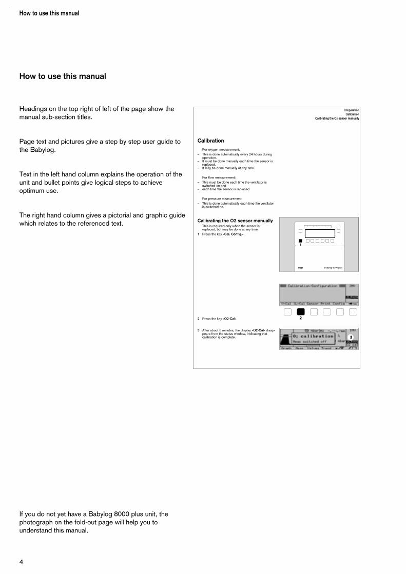
Headings on the top right of left of the page show themanual sub-section titles.
Page text and pictures give a step by step user guide tothe Babylog.
Text in the left hand column explains the operation of theunit and bullet points give logical steps to achieveoptimum use.
The right hand column gives a pictorial and graphic guidewhich relates to the referenced text.
If you do not yet have a Babylog 8000 plus unit, thephotograph on the fold-out page will help you tounderstand this manual.
How to use this manual
4
Calibration
For oxygen measurement:– This is done automatically every 24 hours during
operation.– It must be done manually each time the sensor is
replaced.– It may be done manually at any time.
For flow measurement:– This must be done each time the ventilator is
switched on and– each time the sensor is replaced.
For pressure measurement:– This is done automatically each time the ventilator
is switched on.
Calibrating the O2 sensor manually This is required only when the sensor is replaced, but may be done at any time.
1 Press the key »Cal. Config.«.
2 Press the key »O2-Cal«.
3 After about 5 minutes, the display »O2-Cal« disap-pears from the status window, indicating that calibration is complete.
PreparationCalibration
Calibrating the O2 sensor manually
D Babylog 8000 plus
1
2
3
Contents
5
Contents
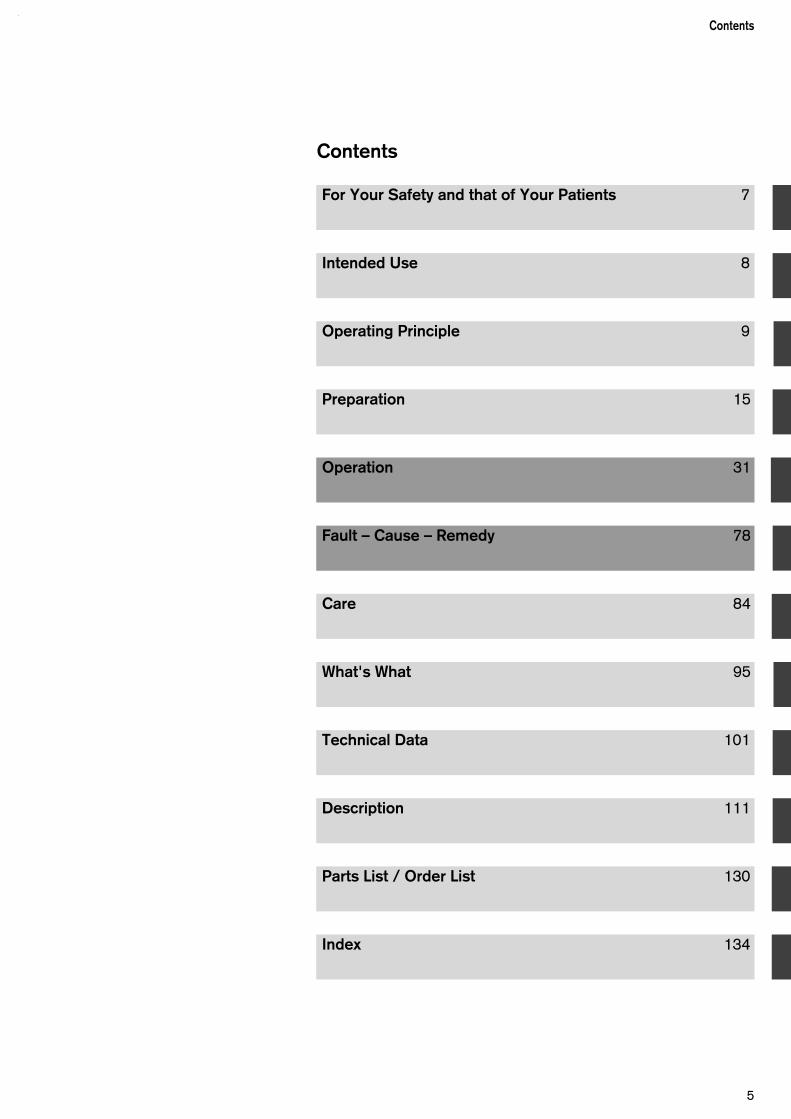
Index 134
For Your Safety and that of Your Patients 7
Intended Use 8
Operating Principle 9
Preparation 15
Operation 31
Fault – Cause – Remedy 78
Care 84
What's What 95
Technical Data 101
Description 111
Parts List / Order List 130

6

For Your Safety and that of YourPatients
Strictly follow the Instructions for Use
Any use of the apparatus requires full understanding andstrict observation of these instructions.The apparatus is only to be used for purposes specifiedhere.
Maintenance
The apparatus must be inspected and serviced regularlyby trained service personnel at six monthly intervals (and a record kept). Repair and general overhaul of the apparatus may only becarried out by trained service personnel.We recommend that a service contract be obtained withDrägerService and that all repairs also be carried out bythem.Only authentic Dräger spare parts may be used for main-tenance. Observe chapter "Maintenance Intervals".
Accessories
Do not use accessory parts other than those in the orderlist.
Not for use in areas of explosion hazard
This apparatus is neither approved nor certified for use inareas where combustible or explosive gas mixtures arelikely to occur.
Safe connection with other electrical equipment
Electrical connections to equipment which is not listed inthese Instructions for Use should only be made followingconsultations with the respective manufacturers or anexpert.
Liability for proper function or damage
The liability for the proper function of the apparatus isirrevocably transferred to the owner or operator to theextent that the apparatus is serviced or repaired bypersonnel not employed or authorized by DrägerServiceor if the apparatus is used in a manner not conforming toits intended use.
Dräger cannot be held responsible for damage causedby non-compliance with the recommendations givenabove. The warranty and liability provisions of the termsof sale and delivery of Dräger are likewise not modifiedby the recommendations given above.
Dräger Medizintechnik GmbH
For Your Safety and that of Your Patients
7
Intended Use
Babylog 8000 plus 5.nLong-term ventilator for premature and newborn babiesand for infants weighing up to 20 kg.It is intended for use on the intensive-care ward.The unit is operated by a doctor or by nursing staff asinstructed by a doctor.All users must be suitably instructed and must be familiarwith the Instructions for Use.
Use of the ventilation modes
– IPPV/IMV (Intermittent Positive Pressure Ventilationand Intermittent Mandatory Ventilation)Controlled ventilation according to a predeterminedpattern and frequency, regardless of the patient'sspontaneous breathing.
– SIPPV (Synchronized Intermittent Positive PressureVentilation)Controlled ventilation with a predetermined pattern orpredetermined tidal volume, synchronised with eachspontaneous breath by the patient.
– SIMV (Synchronized Intermittent MandatoryVentilation)Controlled ventilation with a predetermined pattern orpredetermined tidal volume and frequency, synchro-nised with the patient's spontaneous breathing. Thepatient breathes spontaneously between the synchro-nised ventilation strokes.
– PSV (Pressure Support Ventilation) – optionalSynchronised ventilation with a predetermined inspi-ration pressure or predetermined tidal volume. Thepatient determines the duration of the inspiration andthe ventilation frequency.
– CPAP (Continuous Positive Airway Pressure)Spontaneous breathing with positive airway pressure.
The above ventilation modes can be combined with thefollowing special functions:
– VG (Volume Guarantee) – optionalVolume-controlled ventilation. The units automaticallyregulates the inspiration pressure in order to achievethe predetermined tidal volume.This can be combined with SIPPV, SIMV and PSV.
– HFV (High Frequency Ventilation) – optionalHigh-frequency ventilation for patients weighing up toabout 2 kg. This can be combined with IPPV/IMV orCPAP.
– VIVE (Variable Inspiratory Variable Expiratory Flow)Separately adjustable continuous flow during theexpiration phase of the mandatory ventilation. Thiscannot be combined with HFV.
The ventilator monitorsinspiratory oxygen concentration,airway pressure,tidal volume andbreathing rate (for panting breathing).
The Babylog 8000 plus can be equipped with aninterface for the transfer of measured data and settings tounits such as patient monitors or computers.
If necessary, the ventilator can also be combined with amedical nebulizer.
Always operate the unit under the supervision ofqualified medical personnel in order to allow im-mediate help in the case of a malfunction!
Extractive monitors can generate a vacuum in the airway if the inspirationtube becomes blocked!Connect the sampling line of the extractive monitor onlyvia the adapter with safety valve 84 12 448.
Do not use this ventilator together with flammablegases or anaesthetic agents, as this may incur a fire orexplosion hazard.
Do not use mobile radiotelephones within 10 metresof the ventilator!Mobile radiotelephones may interfere with the functionsof electromedical equipment and thus endanger the life ofthe patient.
If the integrated apnoea monitor is switched off, use aseparate apnoea monitoring device!
Intended Use
8
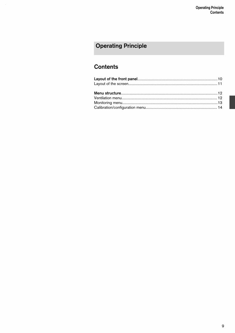
Contents
Layout of the front panel.........................................................................10Layout of the screen.................................................................................11
Menu structure........................................................................................12Ventilation menu....................................................................................... 12Monitoring menu.......................................................................................13Calibration/configuration menu................................................................. 14
Operating PrincipleContents
9
Operating Principle

Layout of the front panel
The front panel consists of the control panel and thedisplay panel with a screen.
Control panel
This carries the keys for ventilation modes and rotaryknobs for adjusting important ventilation parameters.
The rotary knobs which can be adjusted for currentselected ventilation modes are indicated by green LEDs.These LEDs blink if any adjustments are limited internallyor still need to be acknowledged.
1 Rotary knobs for ventilation parameters.
2 Pressing the key »Vent. Mode« selects the menu forventilation modes.
3 Pressing the key »Vent. Option« selects the menu foradditional functions for ventilation modes.
Operating principleLayout of the front panel
10
21 1 1
1 1 13
2-11
24-9
6
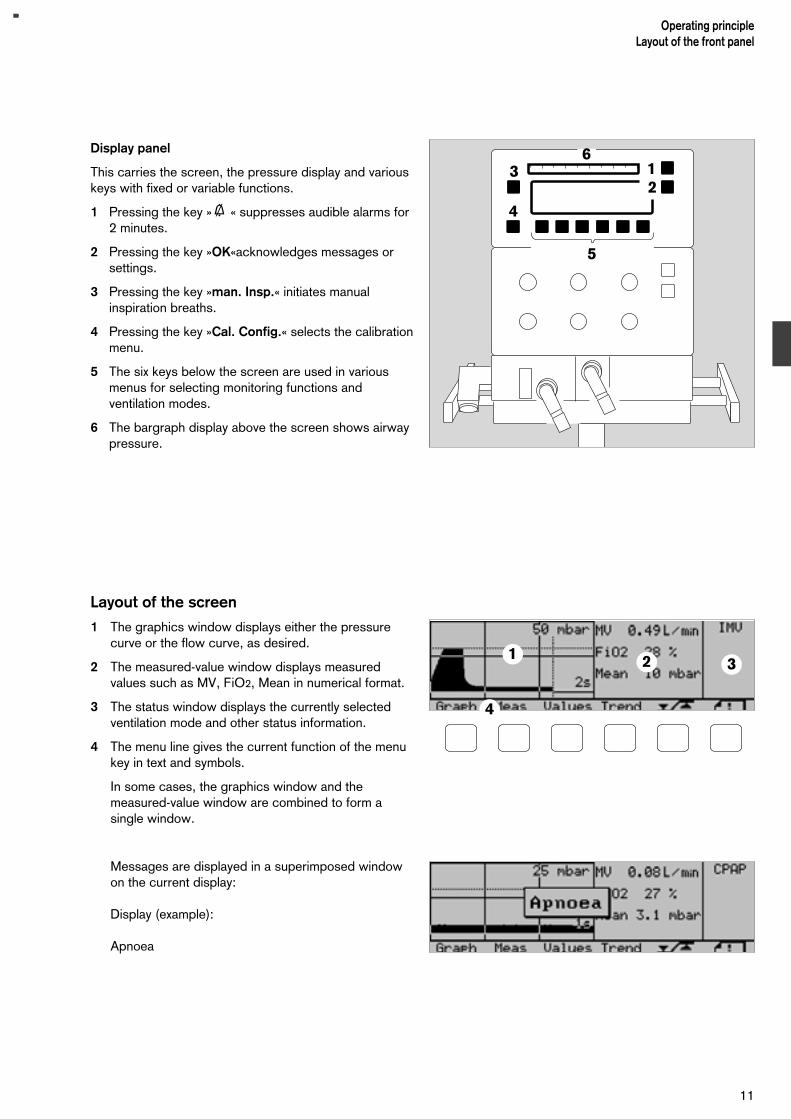
Display panel
This carries the screen, the pressure display and variouskeys with fixed or variable functions.
1 Pressing the key »g « suppresses audible alarms for2 minutes.
2 Pressing the key »OK«acknowledges messages orsettings.
3 Pressing the key »man. Insp.« initiates manualinspiration breaths.
4 Pressing the key »Cal. Config.« selects the calibrationmenu.
5 The six keys below the screen are used in variousmenus for selecting monitoring functions andventilation modes.
6 The bargraph display above the screen shows airwaypressure.
Layout of the screen
1 The graphics window displays either the pressurecurve or the flow curve, as desired.
2 The measured-value window displays measuredvalues such as MV, FiO2, Mean in numerical format.
3 The status window displays the currently selectedventilation mode and other status information.
4 The menu line gives the current function of the menukey in text and symbols.
In some cases, the graphics window and themeasured-value window are combined to form asingle window.
Messages are displayed in a superimposed windowon the current display:
Display (example):
Apnoea
11
Operating principleLayout of the front panel
13
4
2
5
6
321
4

Ventilation menu
Operating principleMenu structureVentilation menu
12

Monitoring menu
13
Operating principleMenu structure
Monitoring menu

Calibration/configuration menu
Operating principleMenu structureCalibration/configuration menu
14

Contents
Mounting Babylog 8000 plus on a trolley............................................... 16
Inserting the expiration valve..................................................................17
Inserting the O2 sensor...........................................................................17
Connecting the gas supply..................................................................... 18
Connecting the electrical supply............................................................ 18
Assembly.................................................................................................19Connecting the ventilation hoses.............................................................. 19Installing the bacterial filter....................................................................... 20Installing the Y-piece and the flow sensor................................................. 21
Before using for the first time................................................................ 22
Calibration...............................................................................................24Calibrating the O2 sensor manually...........................................................24Calibrating the flow sensor....................................................................... 25Replacing the flow sensor.........................................................................27
Checking the unit....................................................................................28
15
PreparationContents
Preparation
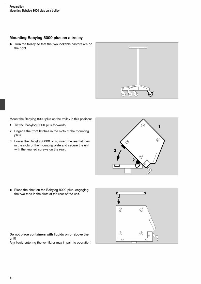
Mounting Babylog 8000 plus on a trolley
Turn the trolley so that the two lockable castors are onthe right.
Mount the Babylog 8000 plus on the trolley in this position:
1 Tilt the Babylog 8000 plus forwards.
2 Engage the front latches in the slots of the mountingplate.
3 Lower the Babylog 8000 plus, insert the rear latchesin the slots of the mounting plate and secure the unitwith the knurled screws on the rear.
Place the shelf on the Babylog 8000 plus, engagingthe two tabs in the slots at the rear of the unit.
Do not place containers with liquids on or above theunit!Any liquid entering the ventilator may impair its operation!
PreparationMounting Babylog 8000 plus on a trolley
16
1
2
3

Inserting the expiration valve Use a sterile expiration valve!
1 Lift the lever upwards to unlock the expiration valve.
Slide the expiration valve as far as possible onto theguide rods.
2 Push the lever down again to lock the expiration valve.
3 Fit the silencer on the exhaust nozzle of the expirationvalve.
Inserting the O2 sensor
This must be done:
– before the ventilator is used for the first time,
– when the sensor is exhausted and can no longer becalibrated.
Unscrew the two slotted screws in the cover on theright-hand side and pull the cover out.
Pull out the exhausted O2 sensor.
Insert the new O2 sensor with the circular printedwiring towards the cover.
Press the cover into place and tighten the twoscrews.
Allow the O2 sensor to run for 15 minutes and thencalibrate the O2 measurement manually (page 24).
Dispose of the old O2 sensor as special waste (page 93).
1
32
17
PreparationInserting the expiration valve
Inserting the O2 sensor
Babylog 8000 plus
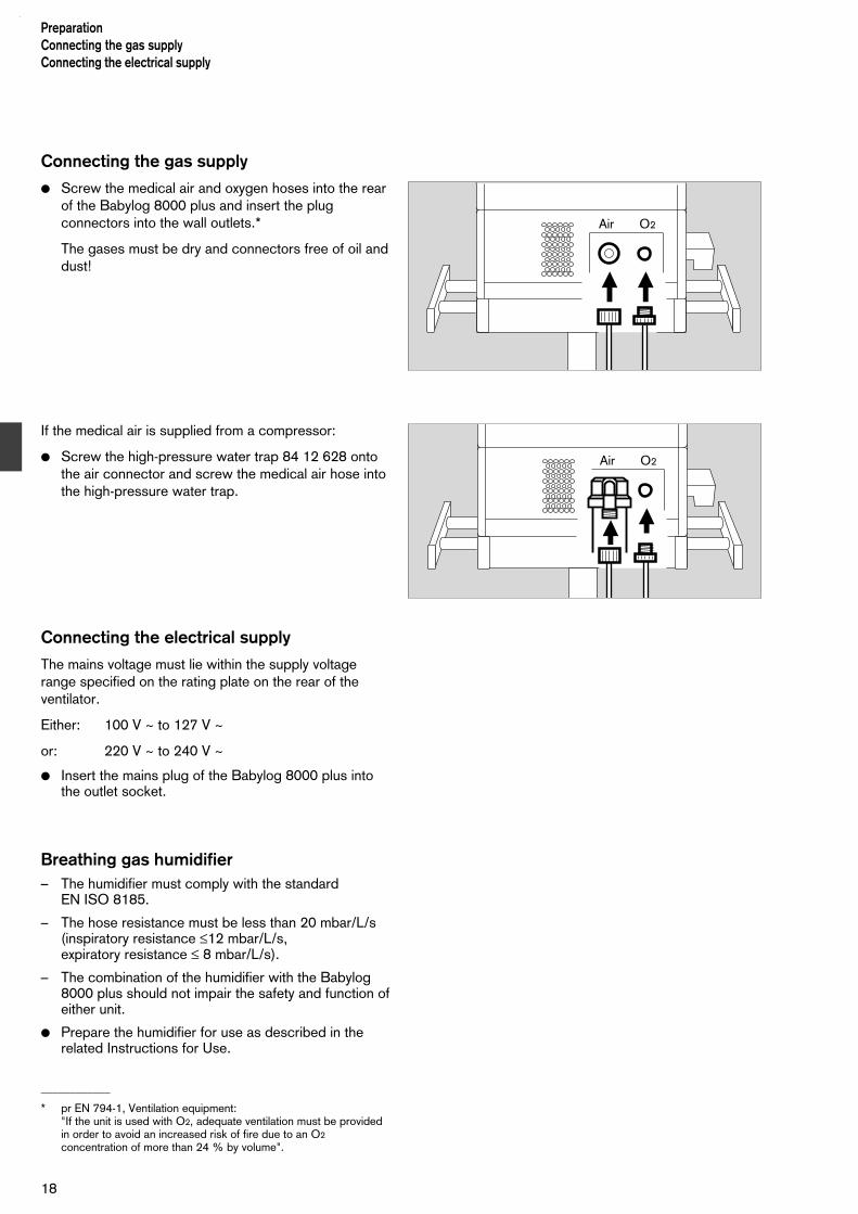
Connecting the gas supply
Screw the medical air and oxygen hoses into the rearof the Babylog 8000 plus and insert the plugconnectors into the wall outlets.*
The gases must be dry and connectors free of oil anddust!
If the medical air is supplied from a compressor:
Screw the high-pressure water trap 84 12 628 ontothe air connector and screw the medical air hose intothe high-pressure water trap.
Connecting the electrical supply
The mains voltage must lie within the supply voltagerange specified on the rating plate on the rear of theventilator.
Either: 100 V ~ to 127 V ~
or: 220 V ~ to 240 V ~
Insert the mains plug of the Babylog 8000 plus intothe outlet socket.
Breathing gas humidifier– The humidifier must comply with the standard
EN ISO 8185.
– The hose resistance must be less than 20 mbar/L/s(inspiratory resistance ≤12 mbar/L/s,expiratory resistance ≤ 8 mbar/L/s).
– The combination of the humidifier with the Babylog8000 plus should not impair the safety and function ofeither unit.
Prepare the humidifier for use as described in therelated Instructions for Use.
____________
* pr EN 794-1, Ventilation equipment:"If the unit is used with O2, adequate ventilation must be providedin order to avoid an increased risk of fire due to an O2
concentration of more than 24 % by volume".
Air O2
PreparationConnecting the gas supply Connecting the electrical supply
18
Air O2
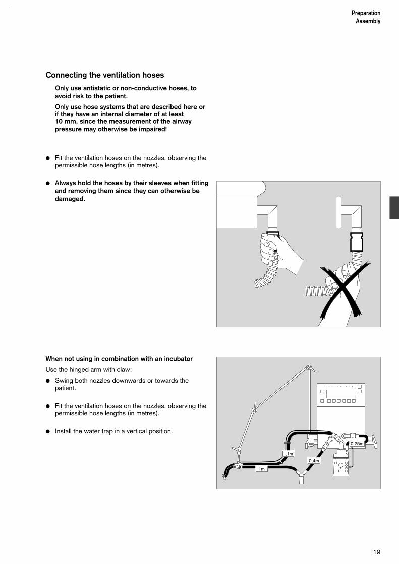
Connecting the ventilation hoses
Only use antistatic or non-conductive hoses, toavoid risk to the patient.
Only use hose systems that are described here orif they have an internal diameter of at least 10 mm, since the measurement of the airwaypressure may otherwise be impaired!
Fit the ventilation hoses on the nozzles. observing thepermissible hose lengths (in metres).
Always hold the hoses by their sleeves when fittingand removing them since they can otherwise bedamaged.
When not using in combination with an incubator
Use the hinged arm with claw:
Swing both nozzles downwards or towards thepatient.
Fit the ventilation hoses on the nozzles. observing thepermissible hose lengths (in metres).
Install the water trap in a vertical position.
19
PreparationAssembly
0,4m
0,25m
1,1m
1m

When using with incubator 8000
Install the water trap in a vertical position.
Mount the holder for the ventilation hoses in theincubator.
Press the rubber sleeves of the ventilation hoses intothe clamp of the holder.
Installing the bacterial filter (optional)
A bacterial filter can be fitted on the inspiration side inorder to protect against contamination.
Use modification kit 84 10 230.
1 Fit the 0.25 metre ventilation hose to the inspirationnozzle.
2 Insert the 15/22 diameter adapter in the ventilationhose.
3 Plug the bacterial filter into the adapter.
4 Plug a size II catheter connector into the bacterialfilter.
Connect the ventilation hoses.
Observe the Instructions for Use for the bacterialfilter.
For high-frequency ventilation (HFV)
Use the "HF Fisher & Paykel" hose set 84 11 153.The low compliance of this hose system reduces thedamping of high frequency oscillations, thus ensuringadequate gas volumes.
Fit the ventilation hoses on the nozzles, observing thepermissible hose lengths (in meters).
Install the water trap in a vertical position.
PreparationAssembly
20
0,25m0,4m
0,25m
0,75m
0,65m
1
2
4
3

Installing the Y-piece and the flow sensor
1 Plug the Y-piece into the ventilation hoses.
2 Plug an ISO flow sensor into the Y-piece.Or:
3 Use a Y-piece with an integrated flow sensor.
4 Insert the plug of the flow-sensor cable into the flowsensor.
Lay the cable along the ventilation hoses to theventilator.
Positioning the Y-piece:The patient side should point about 45° downwards inorder to prevent condensation from collecting in theflow sensor.
5 Insert the plug of the flow-sensor cable into thesocket on the rear of the ventilator and secure it withattached screws.
Connect the test lung to the Y-piece.The test lung consists of a bellows (compliance:0.5mL/mbar), a tracheal tube CH 12, approx. 165 mm long, and a connector.
32
1
4
21
PreparationAssembly
5

When an extractive monitor is used,a vacuum may be generated in the airway if theinspiration hose becomes blocked.
For this reason:
Connect the sampling line of the extractive monitoronly via the adapter with safety valve 84 12 448. TheLuer lock connector must be at the top in order toavoid the formation of condensation.
Before using for the first time
The built-in battery for the power-failure alarm ischarged during normal operation of the ventilator.Before the ventilator is used for the first time, or aftera long idle period, it should be switched on for 30 minutes in order to charge the battery sufficiently.
Use the following settings in order to prevent alarmsduring this charging period:
1 Set the rotary knob »O2-Vol%« to 21
2 Set the rotary knob »Insp. Flow **** « to 5
3 Set the rotary knobs »TI« to 0,4 »TE« to 0,6
4 Set the rotary knob »Pinsp« to 20
5 Set the rotary knob »PEEP/CPAP« to 3.
6 Switch on the ventilator by pressing the power switchon the rear until it locks.
1 3 3
42 5
22
PreparationInstalling the Y-pieceBefore using for the first time
6
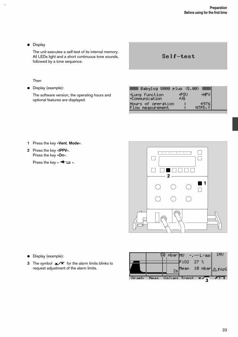
Display
The unit executes a self-test of its internal memory.All LEDs light and a short continuous tone sounds,followed by a tone sequence.
Then
Display (example):
The software version, the operating hours andoptional features are displayed.
1 Press the key »Vent. Mode«.
2 Press the key »IPPV«.Press the key »On«.
Press the key » «.
Display (example):
3 The symbol for the alarm limits blinks torequest adjustment of the alarm limits.
23
PreparationBefore using for the first time
1
2
3

Calibration
For oxygen measurement:
– This is done automatically every 24 hours during operation.
– It must be done manually each time the sensor is replaced.
– It may be done manually at any time.
For flow measurement:
– This must be done each time the ventilator is switchedon and
– each time the sensor is replaced.
For pressure measurement:
– This is done automatically each time the ventilator is switched on.
Calibrating the O2 sensor manually
This is required only when the sensor is replaced, but may be done at any time.
1 Press the key »Cal. Config.«.
2 Press the key »O2-Cal«.
3 After about 5 minutes, the display »O2-Cal« disap-pears from the status window, indicating that calibration is complete.
PreparationCalibrationCalibrating the O2 sensor manually
24
D Babylog 8000 plus
1
2
3

To clear the text message on the screen:
1 Press the key »OK«.
Calibrating the flow sensor
– This must be done each time the ventilator is switchedon,
– each time the sensor is assembled for use and
– each time the flow sensor is replaced.
2 Press the key »Cal. Config.«.
For optimum accuracy:select the flow-sensor type (ISO or Y) so that the flowmeasurement is matched to the sensor being used.
3 Press the key »Sensor«.
Move the cursor to the line Flowsensor » « and
select ISO or Y with the key » « or » «
Select the reference conditions:
NTPD (ambient temperature 20 °C, atmosphericpressure 1013 mbar, dry gas) or
BTPS (body temperature 37 °C, ambient pressure,gas saturated with moisture).
4 Move the cursor to the line Ref. cond. with the key » « .
5 Select NTPD or BTPS with the key » « or » «.
25
PreparationCalibration
Calibrating the O2 sensor manually Calibrating the flow sensor
D Babylog 8000 plus
1
2
D Babylog 8000 plus
3
4 5 5

Calibration:
Press the keys »Cal. Config« and » «.
1 Remove the tube connector and seal the patient sideof the Y-piece with, for example, a sterile glove.No gas may flow through the Y-piece duringcalibration (since the zero point is calibrated).
Display
2 Press the key »Start«.
After about 1 second, the display » « disap-pears from the status window, indicating that thesensor has been calibrated.
Display
Connect the tube again.
If calibration is unsuccessful:
replace the sensor insert or the flow-sensor cable(page 27).
If the flow sensor has to be replaced during operation,and cannot be calibrated immediately, it should benoted that the measuring accuracy may be reduced.
Recalibrate the flow sensor as soon as possible.
If the cable of the flow sensor is temporarilydisconnected, it is not necessary to calibrate thesensor again.
PreparationCalibrationCalibrating the flow sensor
26
1
2

Replacing the insert of the flow sensorThis must be done if the following message isdisplayed:
Flow sensor inopMeas switched off
1 Disconnect the plug from the flow sensor.
2 Press the buttons on both sides and simultaneouslypull the insert out of the Y-piece.
3 Align the two marks and slide the new insert into theY-piece until it locks into position.
1 Connect the plug to the insert again, ensuring that thebar in the insert engages with the slot in the plug.
Calibrate the flow sensor (page 26).
1
3
2
27
PreparationReplacing the flow sensor

Checking the ventilator
The entire check must be executed each time before the ventilator is used.Items 3 to 7 must be checked each time the hose system is replaced.
A copy of this checklist should be available next to the ventilator.
Tick off the items in this checklist next to the ventilator with a pencil and then sign it and enter the date.
Inspection before each use
PreparationChecking the ventilator
28
Checklist for Babylog 8000 plus 5.nKnowledge of the Instructions for Use is essential. Date__________
Babylog 8000 plus 5.n Delete inapplicable items, write in any additional features. ________________Serial No. _________ Signature
What How Check
1 Gas supply Screw the medical air and oxygen hoses intothe rear of the unit, insert the plug.
Hose screwed in tightly, plug connected.
2 Breathing system Expiration valveHosesWater traps
Flow sensor plug
Connect a test lung with tracheal tube CH 12,internal diameter 2.5, and connector to the Y-piece.
Securely seatedCompleteVertical position at lowest point
Plugged in
3 Leak test Switch on the Babylog 8000 plus.
Press the key »OK«,Select ventilation mode CPAP:Press the keys »Vent. Mode«, »CPAP« and»On«.Turn rotary knob »Pinsp« to 80, »Insp. Flow **** « to 2,Press the key »OK«,Press and hold the key »man. Insp.« :
Display Calibrate flow sensor!
Bargraph display: (80 ±2) mbar
4 Functional test Flow calibration Calibrate the flow sensor. Display
Flow sensor calibrated
Airway pressure Set lower MV alarm limit to 0 L/min and upperMV alarm limit to 15 l/min.Select ventilation mode IPPV by setting thefollowing buttons:»Pinsp.« to 20,»Insp. Flow * « to 10,»TI« to 0,4,»TE« to 0,6,»PEEP/CPAP« to 0, then»PEEP/CPAP« to 10,Press the key »OK«.
Ventilation according to the selectedinspiration and expiration times.Bargraph display:insp. (20 ±4) mbar
exsp. (0 ±2) mbar
exsp. (10 ±2) mbar
29
PreparationChecking the unit
What How Check
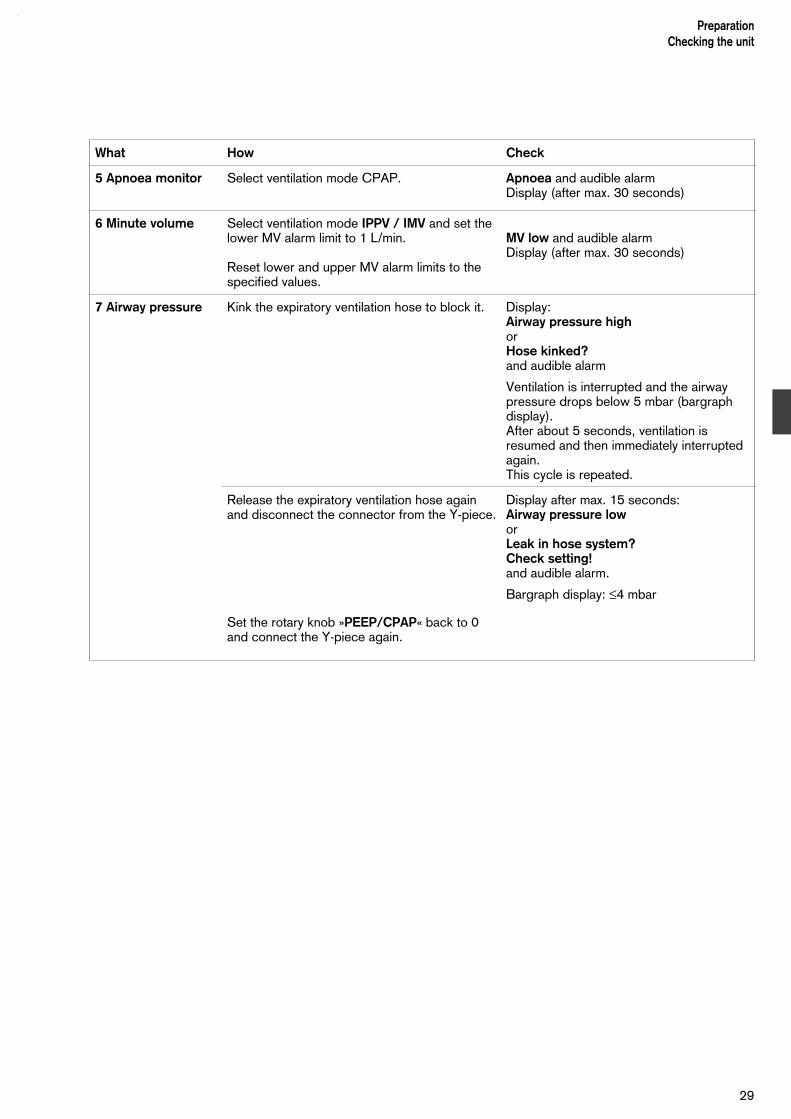
5 Apnoea monitor Select ventilation mode CPAP. Apnoea and audible alarm Display (after max. 30 seconds)
6 Minute volume Select ventilation mode IPPV / IMV and set thelower MV alarm limit to 1 L/min.
Reset lower and upper MV alarm limits to thespecified values.
MV low and audible alarmDisplay (after max. 30 seconds)
7 Airway pressure Kink the expiratory ventilation hose to block it. Display:Airway pressure highorHose kinked?and audible alarm
Ventilation is interrupted and the airwaypressure drops below 5 mbar (bargraphdisplay).After about 5 seconds, ventilation isresumed and then immediately interruptedagain.This cycle is repeated.
Release the expiratory ventilation hose againand disconnect the connector from the Y-piece.
Set the rotary knob »PEEP/CPAP« back to 0and connect the Y-piece again.
Display after max. 15 seconds:Airway pressure loworLeak in hose system?Check setting!and audible alarm.
Bargraph display: ≤4 mbar

30

Contents
Putting into service................................................................................. 32Regular routine.........................................................................................32Switching on............................................................................................ 32
Overview of the Ventilation Modes......................................................... 33
Selecting the Ventilation Mode and Additional Functions......................34Setting the trigger volume.........................................................................35IPPV/IMV................................................................................................. 36SIPPV...................................................................................................... 39SIMV........................................................................................................40PSV......................................................................................................... 41CPAP...................................................................................................... 42Volume guarantee VG.............................................................................. 44High-frequency ventilation HFV.................................................................45High-frequency ventilation with IMV.......................................................... 46Separate Expiratory flow...........................................................................48
Setting the Alarm Limits......................................................................... 49
Special Functions................................................................................... 51Starting inspiration manually..................................................................... 51Nebulizing medicaments........................................................................... 52
Displaying Curves and Measured Values............................................... 55
Displaying Trends................................................................................... 60
Messages on the Logbook......................................................................61
Configuring............................................................................................. 63
Analogue and Digital Interfaces............................................................. 65
Transferring Data to the Patient Monitor................................................ 71
Shutting down.........................................................................................75
31
OperationContents
Operation
Putting into service
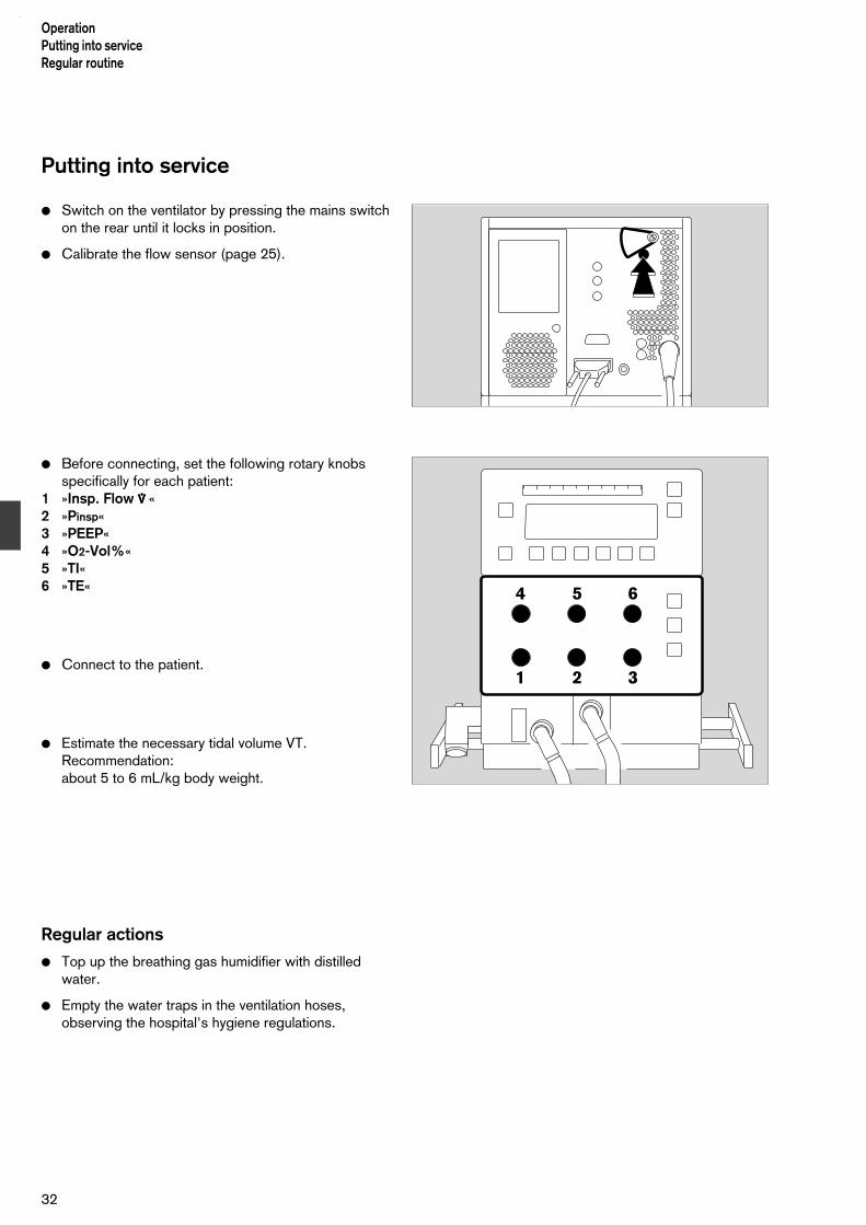
Switch on the ventilator by pressing the mains switchon the rear until it locks in position.
Calibrate the flow sensor (page 25).
Before connecting, set the following rotary knobsspecifically for each patient:
1 »Insp. Flow **** «2 »Pinsp«3 »PEEP«4 »O2-Vol%«5 »TI«6 »TE«
Connect to the patient.
Estimate the necessary tidal volume VT.Recommendation:about 5 to 6 mL/kg body weight.
Regular actions
Top up the breathing gas humidifier with distilledwater.
Empty the water traps in the ventilation hoses,observing the hospital's hygiene regulations.
OperationPutting into serviceRegular routine
32
4 5 6
1 2 3

Overview of the Ventilation Modes
The Babylog 8000 plus can operate in five differentventilation modes, which can also be modified byactivating additional functions.
Ventilation modes
IPPV/IMV Intermittent Positive Pressure Ventilation/Intermittent Mandatory Ventilation Controlled ventilation according to a prede-termined pattern and frequency, regardless ofthe patient's spontaneous breathing.
CPAP Continuous Positive Airway PressureSpontaneous breathing with positive airway pressure.
SIPPV Synchronised Intermittent Positive Pressure VentilationControlled ventilation with a predetermined pattern or predetermined tidal volume, syn-chronised with each spontaneous breath by the patient.
SIMV Synchronised Intermittent MandatoryVentilation Controlled ventilation with a predetermined pattern or predetermined tidal volume and frequency, synchronised with the patient's spontaneous breathing. The patient breathes spontaneously between the synchronised ventilation strokes.
PSV Pressure Support VentilationSynchronised ventilation with a predetermi-ned inspiration pressure or predetermined tidal volume. The patient determines the duration of the inspiration and the ventilation frequency.
Additional functions
VG Volume GuaranteeVolume-controlled ventilation. The unit auto-matically regulates the inspiration pressure in order to achieve the predetermined tidal volume.This can be combined with SIPPV, SIMV andPSV.
HFV High-Frequency VentilationHigh-frequency ventilation for patients weighing up to about 2 kg. This can be combined with IPPV/IMV or CPAP.
33
OperationOverview of the Ventilation Modes
VIVE Variable Inspiratory and Variable ExpiratoryFlowVariable Inspiratory Variable Expiratory flowSeparately adjustable continuous flow during the expiration phase of the mandatory venti-lation. This cannot be combined with HFV.
The following table shows the possible combinations ofventilation modes and additional functions:
IPPV/IMV SIPPV SIMV PSV CPAP
VG
HFV
VIVE

Selecting the Ventilation Mode andAdditional Functions
Example: switching from IPPV/IMV to SIMV withvolume guarantee VG.
1 Press the key »Vent. Mode«.
Press the key »SIMV«For the time being, the Babylog 8000 plus continuesto run in IPPV/IMV mode.
The trigger volume can be adjusted with the keys » « or » «.
Press the key »On«.The Babylog 8000 plus now switches to SIMV mode.
Press the key »VG«.
OperationSelecting the Ventilation Mode and Additional Functions
34
1

Set the desired tidal volume VT with the keys » « or» «.
Press the key »On«.
The Babylog 8000 plus now operates in SIMV modewith volume guarantee.
Exit from the menu:
Press the key» «.
Switching off the additional function VG:
1 Press the key »Vent. Option«.
Press the key »VG« and »Off«.
Exit from the menu:
Press the key » «.
Adjusting the trigger volume (triggersensitivity)
The trigger volume is the volume of gas the patientmust breathe in to trigger a ventilation stroke. It is setin the menu for the ventilation mode or in the menu asan additional function.
Example: setting in the menu for SIMV
Press the key » « for a larger trigger volume (= lower sensitivity).
Press the key » « for a smaller trigger volume (= higher sensitivity).
Recommendation:Start with a low trigger volume (= higher sensitivity).
If self-triggering occurs, increase the trigger volume.Adjustment range: 1 to 10, corresponding to about0.02 to 3 mL.
A larger trigger volume delays the ventilation stroke.
Trigger is displayed each time a ventilation stroke istriggered.
35
OperationSelecting the Ventilation Mode and Additional Functions
Setting the trigger volume
1

IPPV / IMV
Intermittent Positive Pressure VentilationIntermittent Mandatory Ventilation
Time-controlled, pressure-limited ventilation with apredetermined pattern for patients without sponta-neous breathing – with or without pressure plateau.
Switching on IPPV/IMV
Press the keys »Vent. Mode«, »IPPV/IMV«, »On«.
IPPV/IMV can be combined with:
– high-frequency ventilation HFV (page 46)
– separate expiration flow VIVE (page 48).
Ventilating with pressure plateau
The inspiration pressure is limited to Pinsp. If theplateau is so long that the flow drops to zero towardsthe end of the inspiration time, the tidal volume VT isproportional to the ventilation pressure.
VT = (Pinsp – PEEP) · C
C = compliance of the patient's respiratory system.
The tidal volume VT is controlled via the pressure difference PInsp - PEEP.Limiting the pressure to PInsp prevents damaging pressures if, for example, the compliance becomes lower.The pressure plateau promotes the diffusion of the breathing gas in the lungs.
Setting the pressure curve:
Press the keys »Graph« and »Paw«
Display (example):
1 The current setting of the pressure limit PInsp.
2 The end of the currently set inspiration time TE.
Exit from the menu:
Press the key » «.
OperationSelecting the Ventilation Mode and Additional FunctionsIPPV / IMV
36
2
1

Displaying the flow curve:
Press the keys »Graph« and »Flow«.
Exit from the menu:
Press the key » «.
Displaying the measured pressure values:
Press the keys »Meas« and »Pressure«.
Use the rotary knobs »Pinsp«, »PEEP«, »TI«, »TE« and»**** insp« to set the desired ventilation pattern.
Displaying the measured volume values:
Press the key »Vol«.
Adjust the rotary knobs »Pinsp« and »PEEP« so thatthe desired tidal volume VT is applied.
Setting the Alarm Limits: see page 49.
Ventilation without a pressure plateau
This is equivalent to volume-controlled ventilation. Thepeak pressure is determined by the settings for TI and * .
The tidal volume VT is approximately:
VT = TI · * insp · C C + Cs
TI = inspiration time* insp = continuous flowC = compliance of the patient's respiratory
systemCs = compliance of the hose system
The tidal volume VT is controlled with the aid of theflow and the inspiration time.
37
OperationSelecting the Ventilation Mode and Additional Functions
IPPV / IMV

Displaying the pressure curve:
Press the keys »Graph« and »Paw«.
Press the key » «.
Use the rotary knobs »PEEP«, »TI«, »TE« and »**** insp«to set the desired ventilation pattern.
Displaying the flow curve:
Press the keys »Graph« and »Flow«.
Press the key » «.
Displaying the measured pressure values:
Press the keys »Meas« and »Paw«.
Displaying the measured volume values:
Press the keys »Meas« and »Vol«.
Exit from the menu:
Press the key » «.
Adjust the rotary knobs »**** insp« and »TI« so that thedesired tidal volume VT is applied.
Adjust the rotary knob »Pinsp« to the value which isnot to be exceeded.
Setting the Alarm Limits: see page 49.
OperationSelecting the Ventilation Mode and Additional FunctionsIPPV / IMV
38

SIPPV
Synchronized Intermittent Positive PressureVentilation
Ventilation with a predetermined pattern, synchro-nised with the patient's spontaneous breathing. Thepatient determines the ventilation frequency.
If the patient suffers apnoea, ventilation is executed atthe frequency determined by TI and TE.
Press the keys »Vent. Mode«, »SIPPV« and »On«.
Combining SIPPV with VG: see page 44.Combining SIPPV with VIVE: see page 48.
Adjust the rotary knobs »Pinsp«, »PEEP«, »TI« and »**** insp« to obtain the desired ventilation pattern – withor without a plateau, as for IPPV/IMV.
Setting the trigger volume: see page 35.
Adjust the inspiration time »TI« to match the patient´sspontaneous breathing.
Set the frequency of the background ventilation with»TE«.
If self-triggering occurs, increase the trigger volume.
Setting the Alarm Limits: see page 49.
39
OperationSelecting the Ventilation Mode and Additional Functions
SIPPV

SIMV
Synchronized Intermittent Mandatory Ventilation
Ventilation with a predetermined pattern or predeter-mined frequency, synchronised with the patient'sspontaneous breathing. The patient can breathe spon-taneously between the synchronised ventilationstrokes, but does not receive pressure support.
This mode is useful for weaning the patient fromventilation.
If the patient suffers apnoea, ventilation is executed atthe frequency determined by TI and TE.
Press the keys »Vent. Mode«, »SIMV« and »On«
SIMV combined with:
– Combining SIMV with volume guarantee VG: see page 44.
– Combining SIMV with separate expiratory flow VIVE: see page 48.
Adjust the rotary knobs »Pinsp«, »PEEP«, »TI«, »TE«and »**** insp« to obtain the desired ventilation pattern –with or without a plateau, as for IPPV/IMV and thefrequency.
Adjusting the trigger volume: see page 35.
Adjust the inspiration time »TI« to match the patient'sspontaneous breathing.
If self-triggering occurs, increase the trigger volume.
Setting the alarm limits: see page 49.
Operation Selecting the Ventilation Mode and Additional FunctionsSIMV
40

PSV
Pressure Support Ventilation
Pressure-supported ventilation synchronised with thepatient's own breathing. The patient determines theduration of the inspiration and the ventilationfrequency.The ventilation stroke is terminated when the inspira-tory flow drops to about 15 % of the peak flow or, atthe latest, after TI.
This mode is intended for spontaneously breathingpatients with sufficient regulation of their breathingwho are to be supported with an adjustable inspira-tory pressure. Particularly suitable for weaning thepatient from ventilation.
If the patient suffers apnoea, ventilation is executed atthe frequency determined by TI and TE.
Press the keys »Vent. Mode«, »PSV« and »On«.
Combining SIMV with:
– separate expiratory flow VIVE: see page 48.– Combining SIMV with volume guarantee VG:
see page 44.
Adjust the rotary rotary knobs »Pinsp«, »PEEP« and »**** insp« to obtain the desired ventilation pattern. – Ventilate only with a plateau!
The actual inspiration time and the tidal volume are displayed.
Adjust TI for the maximum permissible inspiration time.
Adjust the frequency of the background ventilation with TE .
Adjusting the trigger volume: see page 35.
If self-triggering occurs, increase the trigger volume.
Setting the alarm limits: see page 49.
Use PSV only at a leakage rate of up to about 40 %.
41
OperationSelecting ventilation mode and additional functions
PSV

CPAP
Continuous Positive Airway Pressure
The Babylog 8000 plus applies a continuous flow andadjusts the airway pressure to the PEEP/CPAP level.
Press the keys »Vent. Mode«, »CPAP« and »On«.
Combining CPAP with
– separate expiratory flow VIVE: see page 48.– Combining CPAP with high-frequency ventilation
HFV: see page 45.
Adjust the CPAP level with the rotary knob PEEP/CPAP. Adjust the flow * insp to meet the patient's requirements.
Displaying the flow curve:
Press the keys »Graph« and »Flow«.
Exit from the menu:
Press the key » «.
Displaying the measured pressure values:
Press the keys »Meas« and »Paw«.
Exit from the menu:
Press the key » «.
The mean pressure "Mean" should be the same asthe selected PEEP/CPAP value.
The peak and PEEP values are not displayed inventilation mode CPAP.
Set the rotary knob Pinsp to a value about 5 mbarabove the PEEP/CPAP value.
Displaying the measured volume values:
Press the keys »Meas« and »Vol«.
Exit from the menu:
Press the key » «.
Check the spontaneously breathed volumes.
Setting the alarm limits: see page 49.
Operation Selecting ventilation mode and additional functionsCPAP
42

CPAP with nasopharyngeal tube
Due to the leakage from the patient's mouth, it is notpossible to monitor the minute volume or to check forapnoea. Therefore either switch off flow measurement:
Remove plug from Y-piece.
or
Set lower MV alarm limit to 0 and set apnoea time toOFF (see under "Set alarm limits").
No monitoring of the lower minute volume and noapnoea alarm activation.
Display:
Press the key »OK«. Flow measurement is nowswitched off.
Note that the minute volume is no longermonitored and there is no apnoea alarm!
43
OperationSelecting ventilation mode and additional functions
CPAP

Volume guarantee VG (optional)
This can be combined with the ventilation modesSIPPV, SIMV and PSV.
The inspiratory plateau pressure is automaticallyregulated between Pinsp and PEEP such that the settidal volume VTSET is applied.
VG requires a ventilation mode with a plateau.
This function is used for patients who are to beventilated with a constant tidal volume.
Press the key »Vent. Option«.
Press the key »VG« and set the desired tidal volumeVTSET with the keys » « and » « .
Press the key »On«.The tidal volume and the peak pressure of the regu-lated ventilation stroke are displayed.
Adjust the rotary knobs »TI«, »TE«, »PEEP« and»**** insp« to obtain a ventilation pattern. with a plateau.
Adjust the rotary knob »Pinsp« to the maximumpermissible value which is not to be exceeded.
Exit from the menu:
Press the key » «.
OperationSelecting ventilation mode and additional functionsVolume guarantee VG
44

High-frequency ventilation HFV (optional)
High-frequency ventilation around the PEEP/CPAPlevel, which acts as the mean pressure. The high-frequency pulses are superimposed at the selectedfrequency around the mean pressure.
Suitable for patients with a body weight of up to about2 kg,
for ventilating with reduced stress on the lungs.
Press the keys »Vent. Mode«, »CPAP« and »On«.
Press the key »Vent. Option«.
Press the key »HFV« and move the cursor to the line Frequ. with the key
» «.
Adjust the frequency of the HF oscillations with the keys » « and » «.
Move the cursor to the line Ampl. with the key» «.
Adjust the amplitude with the keys » « and » «.
Press the key »On«.
Adjust the mean airway pressure with the rotary knob »PEEP/CPAP«. This must be at least 3 mbar.
Observe the tidal volume VThf and/or the diffusion coefficient DCO2 and, if necessary, correct the amplitude and frequency.
45
OperationSelecting ventilation mode and additional functions
High-frequency ventilation HFV

High-frequency ventilation with IMV
This is a combination of high-frequency ventilation andintermittent expansion strokes.
During the HF oscillations, the mean pressure is thatset for PEEP/CPAP.
The high-frequency pulses are superimposed at theselected frequency over the mean pressure.
This function is used for flushing the dead spacevolume,
for ventilating with reduced pressure stress on thelungs,
for patients with a body weight of up to about 2 kg.
Press the keys »Vent. Mode«, »IPPV/IMV« and »On«.
Press the key »HFV«and
move the cursor to the line Frequ. with the key » «.
Adjust the frequency of the HF oscillations with the keys » « and » « .
Move the cursor to the line Ampl. with the key » «.
Adjust the amplitude with the keys » « and » «.
Press the key »On«.
Operation Selecting ventilation mode and additional functionsHigh-frequency ventilation with IMV
46

Adjust the mean airway pressure with the rotary knob»PEEP/CPAP«. This must be at least 3 mbar.
Adjust the duration and frequency of the IMV strokeswith the rotary knobs »TI« and »TE«.
Adjust the pressure limiting for the IMV strokes withthe rotary knob »Pinsp«.
Observe the tidal volume VThf and/or the diffusioncoefficient DCO2 and, if necessary, correct theamplitude and frequency.
47
OperationSelecting ventilation mode and additional functions
High-frequency ventilation with IMV

Separating expiratory flow VIVE
VIVE (Variable Inspiratory and Variable Expiratory Flow) The continuous expiratory flow *exp can be adjustedindependently of the continuous inspiratory flow V insp. The inspiratory flow is effective during ventila-tion strokes, while the expiratory flow is effectiveduring spontaneous breathing phases.
An increased expiratory flow *exp can be used inorder to
– provide the patient with a higher flow for spontaneousbreathing than that used for the ventilation strokes;
– promote flushing of the dead space volume in the Y-piece by means of increasing turbulence in the hosesystem;
– permit separate adjustment of the pattern of manuallyinitiated ventilation strokes in CPAP mode.
A reduced expiratory flow *exp can be used in orderto save oxygen and thus reduce costs.
Press the key »Vent. Option«.
Press the key »VIVE« and adjust the expiratory flowwith the keys » « and » «.
Press the keys »On« and » «
Operation Selecting ventilation mode and additional functionsSeparating expiratory flow VIVE
48

Setting alarm limits
The alarm limits for monitoring of the following parameters are set automatically:
Airway pressure
Upper alarm limit for ventilation strokes: Pinsp + 5 mbar
Upper alarm limit for expiration or CPAP: PEEP/CPAP + 4 mbar
Lower alarm limit: PEEP/CPAP – 2 mbar
Alarm limit for disconnection: Pinsp – PEEP + PEEP
4
O2 concentration
Upper alarm limit: »O2-Vol.%« + 4 Vol.%
Lower alarm limit: »O2-Vol.%« – 4 Vol.%
For a description of the alarm criteria, see "TechnicalData" on page 106.
Manual adjustmentis used for the alarm limits for minute volume MV,apnoea and breathing frequency:
Lower alarm limit MV : from 0 to upper alarm limit
Upper alarm limitMV : from lower alarm limit to
15 L/min
»Alarm delay« time: 0 to 30 seconds(delays the alarms "MV low" and "VT low")
Apnoea time: 5 to 20 seconds.Over 20 seconds = OFF.When ventilating very small patients, the apnoea monitoring can be switched off in order to avoid false alarms.In this case, a separate apnoeamonitoring device must be used!
»Panting« frequency: 20 to 200 bpm.
Less than 20 bpm = OFF.
49
OperationSetting alarm limits
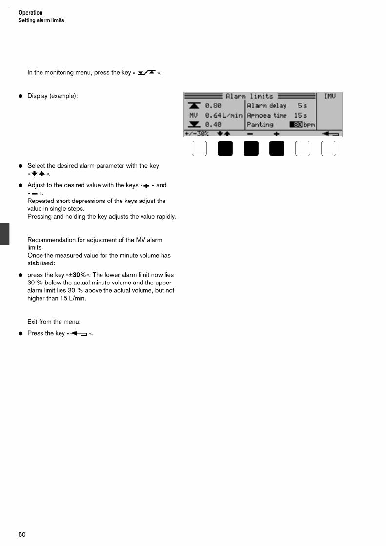
In the monitoring menu, press the key » «.
Display (example):
Select the desired alarm parameter with the key » «.
Adjust to the desired value with the keys » « and » «. Repeated short depressions of the keys adjust thevalue in single steps.Pressing and holding the key adjusts the value rapidly.
Recommendation for adjustment of the MV alarmlimitsOnce the measured value for the minute volume hasstabilised:
press the key »±30%«. The lower alarm limit now lies 30 % below the actual minute volume and the upper alarm limit lies 30 % above the actual volume, but not higher than 15 L/min.
Exit from the menu:
Press the key » «.
50
OperationSetting alarm limits

Special functions
Starting inspiration manually
This function is active in any ventilation mode,regardless of the TI and TE settings.
All other parameter settings remain effective.
1 Limit the inspiration pressure with the rotary knob»Pinsp.«.
2 Press and hold the key »man Insp.« for as long as theinspiration is to last, for example for X-ray examinationof the thorax with maximum inspiration.The inspiration is terminated after a maximum of 5 seconds and a further inspiration is possible onlyafter a waiting period of 5 seconds.
Display (example):
51
OperationSpecial functions
Starting inspiration manually
2
1

Nebulizing medicaments (optional)
This is possible in any ventilation mode.
Pre-requisites:
medical-air socket on the rear of the ventilator andmodification kit 84 11 025.
Aerosols may block the expiration valve, thusimpairing ventilation. For this reason, the expira-tion valve must be replaced by a clean, sterile oneimmediately after nebulization.
Aerosols may block the filters, thus impairingventilation.
Do not install microbacterial filters on the outlet side ofthe nebulizer or in the expiration side.
Preparation
Install the coupling:
1 On the left side of the ventilator, remove the lowersecuring screw of the case with a coin and secure thecoupling under this screw.
2 Push the plug into the socket on the rear of theventilator until it locks into position.
Prepare the nebulizer for use as described in therelated Instruction for Use and then
3 insert the nozzle in the outlet and
4 insert an 11 mm diameter catheter connector into theinlet.
Open the inspiration hose and connect the nebulizerbetween then open ends.
2 1
OperationSpecial functionsNebulizing medicamentsPreparation
52
34

When using with an incubator
Insert the outlet of the nebulizer in the top hose portof the incubator.
When using without an incubator
Press the rubber sleeve into the clip on the hingedarm.
Adjust the nebulizer to a vertical position and fill it.
Since the flow sensor would be soiled by medicamentaerosols,
first:
1 disconnect the plug from the flow sensor and
acknowledge the resulting alarm on the Babylog 8000plus.
Then:
2 pull out the sensor insert and
3 fit the sealing plug 84 11 024 (provided in theconversion kit "Medicament nebulizer").
Remember that there is no monitoring of theminute volume and no apnoea alarm when the flow sensor is not fitted!
53
OperationSpecial functions
Nebulizing medicaments
1
23

Starting nebulization
1 Insert the plug of the supply line into the socket andpress it in until it locks.
Features of medicament nebulization
The nebulizer nebulizes continuously, but theaerosol generate during expiration does not enterthe lungs.
Since the nebulizer is driven by medical air, theoxygen concentration FiO2 drops and, duringnebulization, is not the same as the indicatedvalue.
If FiO2 must remain constant:
Increase the oxygen concentration with the rotaryknob »O2-Vol%« for the duration of the aerosol application.The necessary setting can be determined from thediagram on the right.
Example:
Insp. Flow * = 10 L/minO2-Vol.% = 80 Vol.%
during application of the aerosol, set the rotary knob»O2-Vol%« to about 90 vol.%.
Discontinuing nebulization
2 Pull the socket back to release the plug.
Empty any remaining medicament from the nebulizer,remove the nebulizer from the ventilator and preparethe nebulizer for re-use as described in the relatedInstructions for Use.
Install the insert in the housing of the flow sensor andinsert the plug.
Fit a clean expiration valve (page 17).
54
OperationSpecial functionsNebulizing medicaments
100
90
80
70
60
50
40
30
201 2 4 6 8 10 12 14 16 18 20 22 24 26 28
100
90
80
70
60
50
40
30
21
O2 Vol.%
resultierende FiO2
[Vol.%]
Insp. Flow * [L/min]
1
2
resulting FiO2

Displaying curves and measuredvalues
Airway pressure curve Paw
In the monitoring menu, press the keys »Graph« and»Paw«.
Display (example):
1 Pressure axis scale (50 mbar)
2 Pressure limit »Pinsp.«(dotted horizontal line)
3 Time axis scale (2 s)
4 End of selected expiration time TE(dotted vertical line)
Exit from the menu:
Press the key » «.
Displaying the flow curve
In the monitoring menu, press the keys »Graph« and»Flow«.
Display (example):
1 Flow axis scale (10 L/min)
2 Zero line
3 Time axis scale (2 s)
4 End of selected expiration time TE(dotted vertical line)
Exit from the menu:
Press the key » «.
55
OperationDisplaying curves and measured values
Airway pressure curve PawFlow curve ****
1
1
2
3
2
3
4
4

Freezing curves
In the sub-menu »Graph«, press the key »Stop«.
Cancelling the freeze function:
Press the key »Stop« again. Continuous monitoring ofthe curve is resumed.
Exit from the menu:
Press the key » «.
Displaying measured pressure values In the monitoring menu, press the keys »Meas« and
»Paw«.
Display (example):
Peak = peak pressure of the preceding breathing cycle
Mean = mean pressure of the preceding breathing cycle
PEEP = final expiratory pressure of the preceding breathing cycle
Exit from the menu:
Press the key » «.
56
Operation Displaying curves and measured valuesFreezing curvesMeasured pressure values

Displaying lung values
The Babylog 8000 plus calculates the resistance andcompliance of the patient's lung using linear regressionanalysis.
In the monitoring menu, press the keys »Menu« and»RC«.
R = resistance of the airway, including the tube
C = dynamic compliance of the respiratory system
TC = time constant of the respiratory system in milliseconds
C20/C = index which indicates overdistension of the lungs:C20/C < 0.8: lungs may be overdistended.This can only be used with ventilation modes using no plateau (see page 125).
r = correlation coefficient of the linear regression analysis
See page 125 for calculation of the parameters.After manual inspiration, the display of the ventilationcurves is automatically frozen for one minute. Thecurves and the related measured values can then beassessed together.
Switching curves: see page 55Cancelling the "freeze" function: see page 56
If the warning symbol is displayed beside the value forr, the measured values may be false due, for example,to a leak.
Exit from the menu:
Press the key » «.
Displaying measured volume values
In the monitoring menu, press the keys »Meas« and»Vol«.
Display (example):
MV = expiratory minute volume
spont. = spontaneous breathing component of the minute volume (in %)
Leak = Leak in the tube (see the description in the Appendix, page 123)
VT = expiratory tidal volume of the preceding breathing cycle
Exit from the menu:
Press the key » «.
57
OperationDisplaying curves and measured values
Displaying lung valuesMeasured volume values

Combinations of measured values
In the monitoring menu, press the keys »Meas« and »MV O2 P«.
Display (example):
MV = expiratory minute volume
FiO2 = measured inspiratory oxygen concentration
Mean = mean value of the airway pressure of the preceding breathing cycle
Exit from the menu:
Press the key » «.
Displaying the measured volume values ofhigh-frequency ventilation (HFV)
In the monitoring menu, press the keys »Meas« and »HFVol«.
Display (example):*
MVmin = inspiratorially measured minute volume L/min] resulting from mandatory ventilation
DCO2 = gas transport coefficient [mL2/s]
DCO2 = VTHf 2 · f
f = frequency [Hz] of the high-frequency pulses
VTim = inspiratorially measured tidal volume [mL] of mandatory ventilation
VTHf = inspiratorially measured tidal volume [mL] of high-frequency ventilation
Exit from the menu:
Press the key » «.
____________* Only if the HFV option is installed
See the Appendix, page 120, for a detailed description of HFV.
58
OperationDisplaying curves and measured valuesCombinations of measured valuesMeasured volume values for HFV
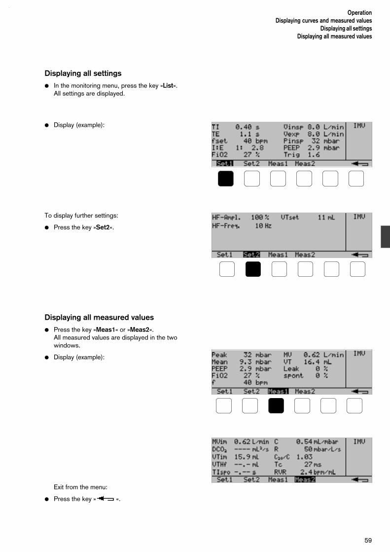
Displaying all settings
In the monitoring menu, press the key »List«.All settings are displayed.
Display (example):
To display further settings:
Press the key »Set2«.
Displaying all measured values
Press the key »Meas1« or »Meas2«.All measured values are displayed in the twowindows.
Display (example):
Exit from the menu:
Press the key » «.
59
OperationDisplaying curves and measured values
Displaying all settingsDisplaying all measured values

Displaying trends
The trends of some of the measured values over thepreceding 24 hours are stored in the trend memory,namely:
FiO2 Inspiratory oxygen concentrationMean Mean pressureMV Minute volumeC Dynamic complianceR ResistanceRVR* Rate Volume Ratio
the ratio breathing rate (frequency) : tidal volume (see page 127)
In the monitoring menu, press the key »Trend«.
Display (example):
A window containing a section of the contents of thetrend memory is displayed. The width of this windowand its position within the memory can be adjusted asrequired.
Select the desired measured value with the key»Param«.
Adjust the width of the window with the keys » « and » «. The maximum width is 24hours and the minimum width is 2 hours. The timesdisplayed are the beginning and end of the selectedsection.
Move the window as required with the keys » «and » «:
1 Slider at the left end of the bar:the window is located at the beginning of the trendmemory.
2 Slider at the right end of the bar:the window is located at the end of the trend memory.
Exit from the menu:
Press the key » «.
____________* RVR can be used as an indicator for the chances of successful
weaning from the respirator.
OperationDisplaying trends
60
2
1

61
OperationMessages and log
D Babylog 8000 plus
Messages
are displayed in a hierarchical sequence, dependingon their importance. If, for example, two faults aredetected simultaneously, the message for the morecritical fault will be displayed first.The messages are displayed in a window which issuperimposed on the existing screen display.
At the same time, one of three specified tone sequen-ces sounds in order to indicate the importance of themessage.
Display (example):
The message disappears when its cause no longerexists.
Alarm messagesThe red alarm lamp blinks and an intermittent tonesounds.
The alarm indicates a life threatening situation, suchas a kinked hose, immediate action is necessary.
Caution messagesThe red alarm lamp blinks and a three-tone sequencesounds repeatedly.
Caution messages indicate situations where actionwill be required soon in order avoid a potential lifethreatening situation. You should react accordinglyand rectify the situation within 2 minutes.
Advisory messagesThe tone sequence sounds once.
Advisory messages remind you of special functions ordraw your attention to a specific situation.
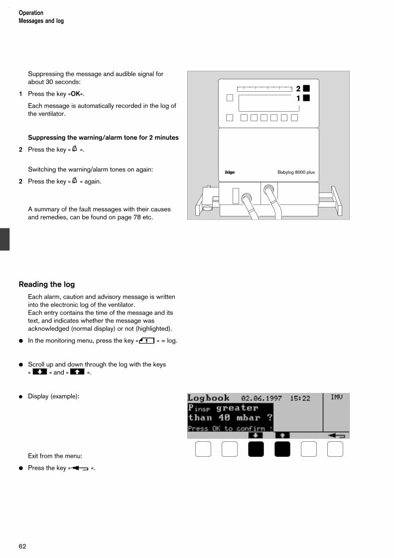
Suppressing the message and audible signal forabout 30 seconds:
1 Press the key »OK«.
Each message is automatically recorded in the log ofthe ventilator.
Suppressing the warning/alarm tone for 2 minutes
2 Press the key »g «.
Switching the warning/alarm tones on again:
2 Press the key »g « again.
A summary of the fault messages with their causesand remedies, can be found on page 78 etc.
Reading the log
Each alarm, caution and advisory message is writteninto the electronic log of the ventilator.Each entry contains the time of the message and itstext, and indicates whether the message wasacknowledged (normal display) or not (highlighted).
In the monitoring menu, press the key » « = log.
Scroll up and down through the log with the keys » « and » «.
Display (example):
Exit from the menu:
Press the key » «.
D Babylog 8000 plus
12
OperationMessages and log
62

Configuration
Setting time and date
Press the keys »Cal. Config.«, »Config« and »Clock«.
Use the keys » « and » « to highlight theparameter to be changed.(Example: 02).
Adjust the value with the keys » « and » «.
Display (example):
Exit from the menu:
Press the key » «.
The setting remains stored even if the ventilator isswitched off.
Adjusting the loudness of the alarm tone
Press the keys »Cal. Config.«, »Config« and » llll«.
Display (example):
Adjust the loudness with the keys » « and » «. Each time a key is depressed, a test tonesounds with the currently selected loudness.The vertical bargraph represents the loudness.
Exit from the menu:
Press the key » «.
The setting remains stored even if the ventilator isswitched off.
63
OperationConfiguration
Time and dateLoudness of alarm tone

Adjusting the screen contrast
This can be done only on units with an LCD screen.The screen contrast can be optimised to suit theuser's viewing angle.
Press the keys »Cal. Config.«, »Config« and »Contr«:
Display (example):
A test pattern is displayed on the screen.
Adjust the contrast with the keys » « and » « for optimum visibility.
Exit from the menu:
Press the key » «.
The setting remains stored even if the ventilator isswitched off.
Selecting the display text language
Available are: american, german, english, spanish,french, italian, dutch, japanese and swedish.
Press the keys »Cal. Config.«, »Config« and »Language«:
Display (example):
Select the desired language with the keys » «and » «.
Exit from the menu:
Press the key » «.
The setting remains stored even if the ventilator isswitched off.
OperationConfigurationScreen contrastDisplay text language
64
Analogue and digital interfaces(optional)
These interfaces can be used for:analogue output of measured values,output of reports,communication with a patient monitor or a personalcomputer with, for example, the programme BabyView(or a similar programme) for graphical and numericalpresentation of ventilation parameters.
All transmitted data are for information only andshould not be used as the sole basis fortherapeutical decisions!
The connected devices should be installed in thesame room as the Babylog 8000 plus, and not lessthan 1.5 metres away from the patient.*
Each of the two analogue outputs transmits one ofthe available measured values.
The RS232 interfaceis used to send information to a printer, namely:
– reports,– contents of the trend memory,– measured-value curves
or – to send data to a patient monitor or a PC.
The pulse output indicates the following events:
– triggered mandatory stroke,– mandatory stroke,– alarm.
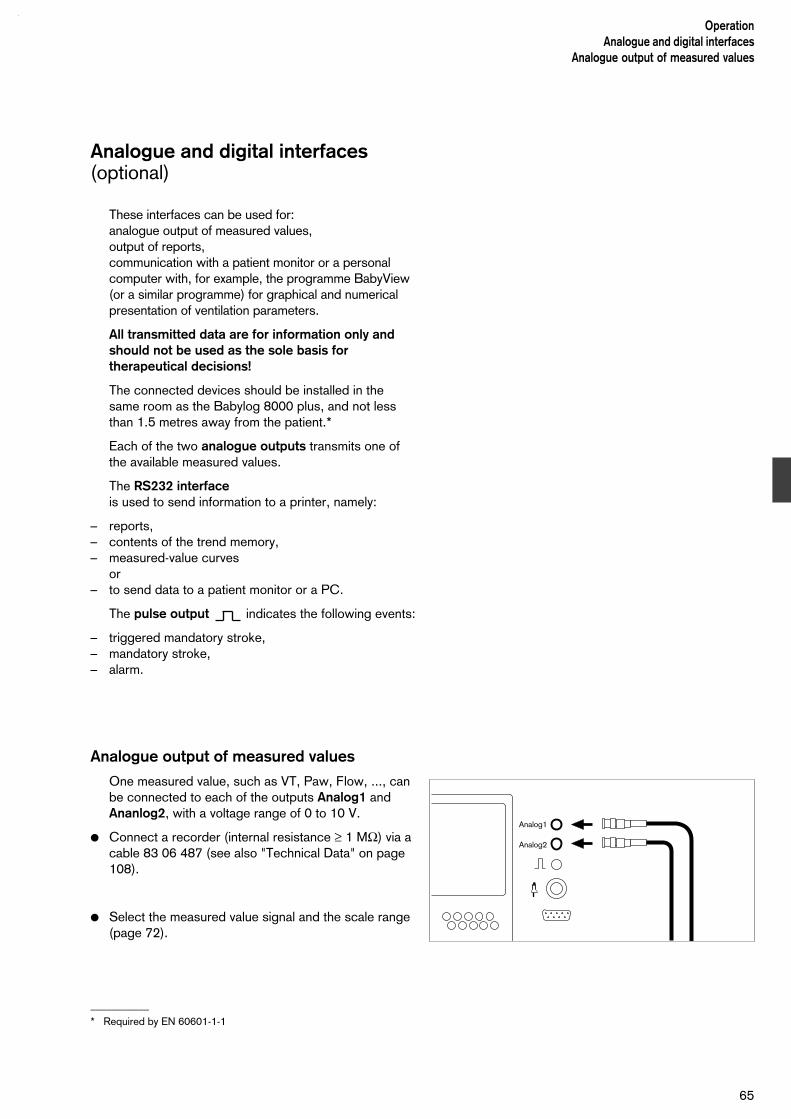
Analogue output of measured values
One measured value, such as VT, Paw, Flow, ..., can be connected to each of the outputs Analog1 and Ananlog2, with a voltage range of 0 to 10 V.
Connect a recorder (internal resistance ≥ 1 MΩ) via acable 83 06 487 (see also "Technical Data" on page108).
Select the measured value signal and the scale range(page 72).
___________
* Required by EN 60601-1-1
65
OperationAnalogue and digital interfaces
Analogue output of measured values
Analog1
Analog2
– Signal from pulse output
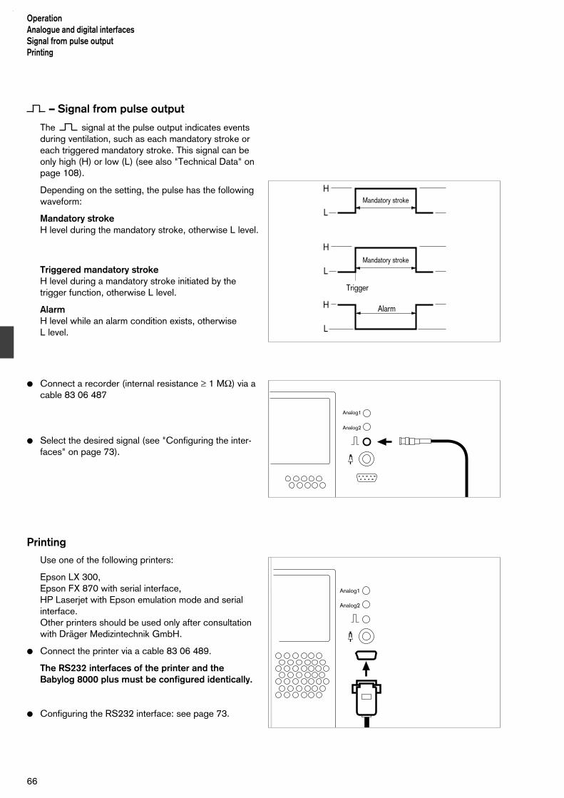
The signal at the pulse output indicates eventsduring ventilation, such as each mandatory stroke oreach triggered mandatory stroke. This signal can beonly high (H) or low (L) (see also "Technical Data" onpage 108).
Depending on the setting, the pulse has the followingwaveform:
Mandatory strokeH level during the mandatory stroke, otherwise L level.
Triggered mandatory strokeH level during a mandatory stroke initiated by thetrigger function, otherwise L level.
AlarmH level while an alarm condition exists, otherwise L level.
Connect a recorder (internal resistance ≥ 1 MΩ) via acable 83 06 487
Select the desired signal (see "Configuring the inter-faces" on page 73).
Printing
Use one of the following printers:
Epson LX 300,Epson FX 870 with serial interface,HP Laserjet with Epson emulation mode and serialinterface.Other printers should be used only after consultationwith Dräger Medizintechnik GmbH.
Connect the printer via a cable 83 06 489.
The RS232 interfaces of the printer and theBabylog 8000 plus must be configured identically.
Configuring the RS232 interface: see page 73.
OperationAnalogue and digital interfacesSignal from pulse outputPrinting
66
Trigger
Alarm
mandat. Hub
mandat. Hub
H
L
H
L
H
L
Analog1
Analog2
Analog1
Analog2
Mandatory stroke
Mandatory stroke

Press the key »Cal. Config.«:
Press the key »Print«.
Display (example):
Printing reports
This function is used for documenting measuredvalues, settings and the status of the ventilator.
Example:
To print a report once:
Press the key »Select« repeatedly until »Report« ishighlighted.
Start printing by pressing the key »Start«. Thefunction of this key then changes to »Stop«.
During printing of the report, the functions "All" and"BabyLink" are not available. One of the otherfunctions may be started, but printing starts only aftercompletion of the report output.
To cancel the printing operation:
Press the key »Stop«.
67
OperationAnalogue and digital interfaces
Printing reports
|15:39 23.08.1997 IPPV Babylog 8000plus|
| |
|Einstellwerte: |Messwerte: |
|TI: 0,40s Pinsp: 25,0 mbar |FiO2: 21 % Mean: 10,1 mbar |
|TE: 0,80s PEEP: 4,0 mbar |Leck: 0 % Peak: 25,0 mabr |
|I:E: 1:2 FiO2: 21 % |spont: 0 % PEEP: 4,0 mbar |
|fset: 50 bpm | f: 50 bpm |
| Flow in:9,6 L/min |VT: 15 mL |
| Flow ex:9,6 L/min |MV: 0,75 L/min TIspont:-,--s |
|HFV: |HFV: |
|HfFrequ:10Hz HfAmpl: 100 % |VTim: 11 mL MVim:0,75 L/min |
| |VTHf: --- mL DCO2:---- mL^2/ |
|VG: |LFT: |
|VTset: 10,0 mL |C: 0,75 mL/mbar R: 85 mbar/mL/s |
| |C20/C: 1,67 TC: 64 s |
|VIVE: aus Trigger: 10,0 |Flow-Messung: |
| |NTPD ISO FiO2-kompensiert|
+----------------------------------------------------------–-––-----+
+--------------------------------------------------------–----–-----+
+-----------------------------------------------------------––------+
+---------------------------------------------------------–--–------+
+----------------------------------------------------------–-–------+
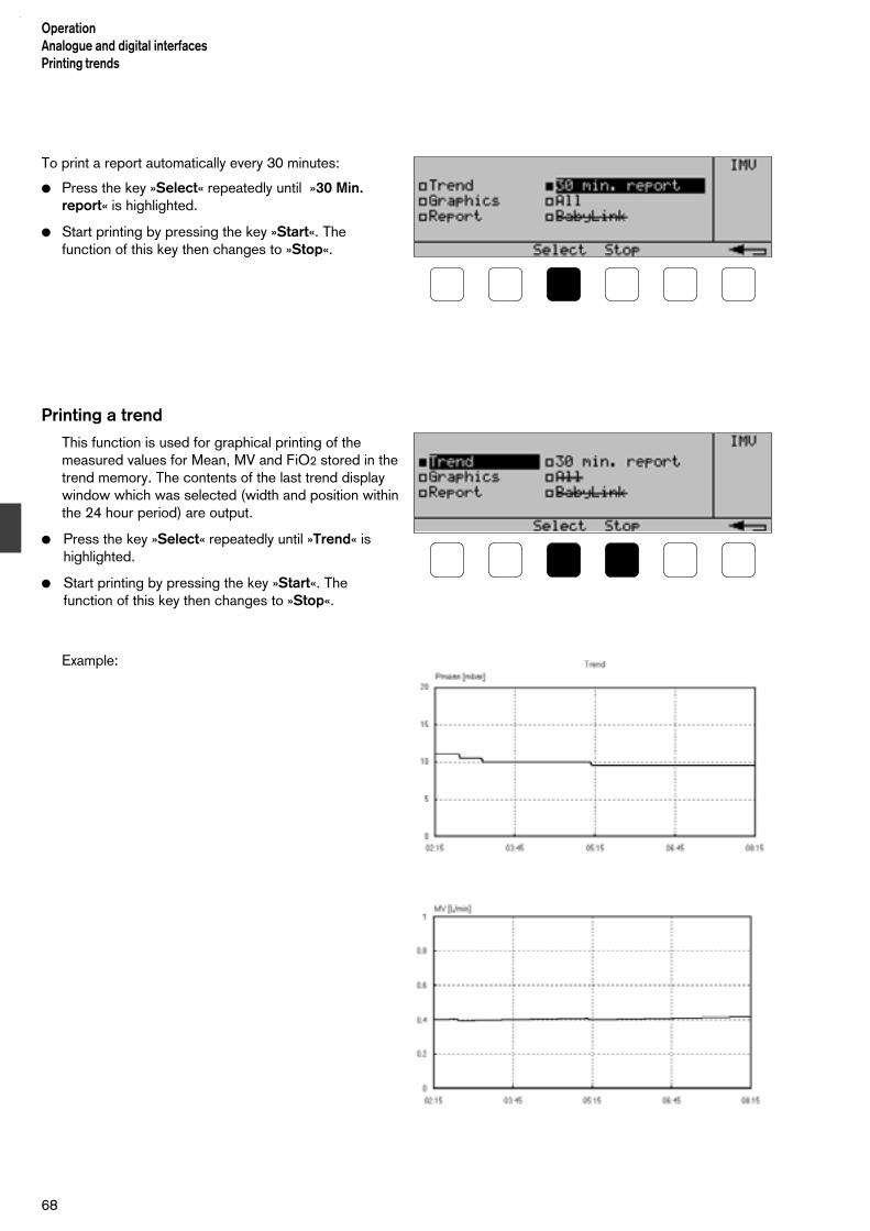
To print a report automatically every 30 minutes:
Press the key »Select« repeatedly until »30 Min.report« is highlighted.
Start printing by pressing the key »Start«. Thefunction of this key then changes to »Stop«.
Printing a trend
This function is used for graphical printing of themeasured values for Mean, MV and FiO2 stored in thetrend memory. The contents of the last trend displaywindow which was selected (width and position withinthe 24 hour period) are output.
Press the key »Select« repeatedly until »Trend« ishighlighted.
Start printing by pressing the key »Start«. Thefunction of this key then changes to »Stop«.
Example:
OperationAnalogue and digital interfacesPrinting trends
68

To cancel the printing operation:
Press the key »Stop«.
Printing curves
This function is set for graphical printing of the curves:
airway pressure,flow andtidal volume.
Press the key »Select« repeatedly until »Graph« ishighlighted.
Start printing by pressing the key »Start«. Thefunction of this key then changes to »Stop«.
To cancel the printing operation:
Press the key »Stop«
Example:
69
OperationAnalogue and digital interfaces
Printing trendsPrinting curves
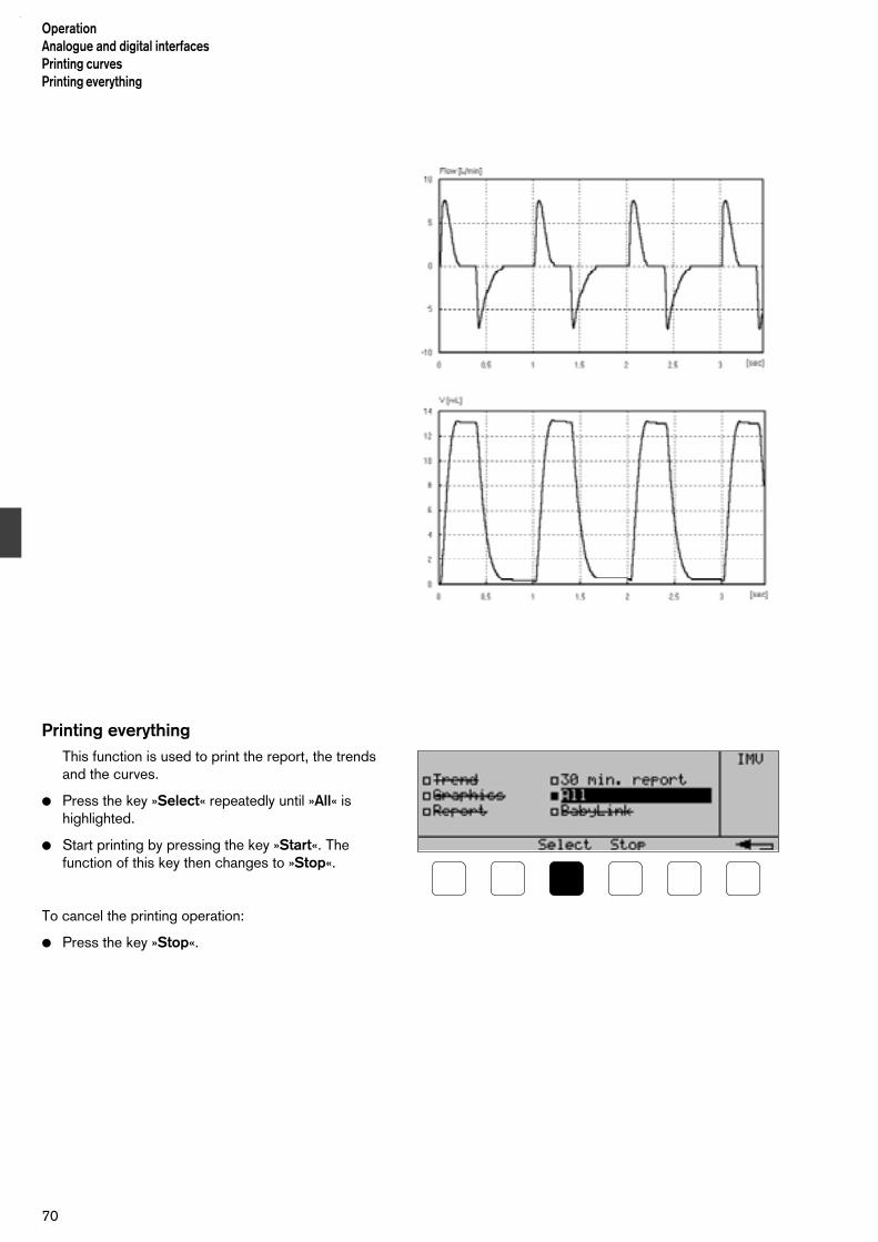
Printing everythingThis function is used to print the report, the trendsand the curves.
Press the key »Select« repeatedly until »All« ishighlighted.
Start printing by pressing the key »Start«. Thefunction of this key then changes to »Stop«.
To cancel the printing operation:
Press the key »Stop«.
OperationAnalogue and digital interfacesPrinting curvesPrinting everything
70

Transmitting data to a patientmonitor
This function is set for connection of a device(monitor, PC) which uses the BabyLink transmissionprotocol. For more details, see the "BabyLink"manual.
Connect the monitor via a cable 83 06 488.
Press the key »Select« repeatedly until »BabyLink« ishighlighted.
Start transmission by pressing the key »Start«. Thefunction of this key then changes to »Stop«.
To cancel the transmission:
Press the key »Stop« .
Configuring the interfaces
This function is used to programme the RS232 interface,the analogue interfaces and the pulse output.
Press the key »Cal. Config«, »Config« and »Com«.
Display (example):
Selecting the signals and scales for Analog1 and Analog2
Press the key »Param« repeatedly until »Analog1« ishighlighted.
Select the desired signal with the keys » « and » « .
Press the key »Param« and then select the desiredscale value with keys » « and » «.
Repeat the above steps for output Analog2.
The setting remains stored even if the ventilator isswitched off.
71
OperationTransmitting data to patient monitor
Configuring the interfacesSignals and scales

The following signals and scales can be selected:
Airway pressure –10 . . .90 mbar –> 0 . . .10 VAirway pressure – 5 . . .45 mbar –> 0 . . .10 V
Mean airway pressure –10 . . .90 mbar –> 0 . . .10 VMeanairway pressure – 5 . . .45 mbar –> 0 . . .10 V
FiO2 0 . .100 Vol.% –> 0 . . .10 V
Flow –40 . . .40 L/min –> 0 . . .10 VFlow –20 . . .20 L/min –> 0 . . .10 VFlow –10 . . .10 L/min –> 0 . . .10 VFlow – 5 . . . .5 L/min –> 0 . . .10 V
Volume 0 . . 500 mL –> 0 . . .10 VVolume 0 . . 100 mL –> 0 . . .10 VVolume 0 . . . 50 mL –> 0 . . .10 VVolume 0 . . . 25 mL –> 0 . . .10 V
Tidal volume 0 . . 500 mL –> 0 . . .10 VTidal volume 0 . . 100 mL –> 0 . . .10 VTidal volume 0 . . . 50 mL –> 0 . . .10 VTidal volume 0 . . . 25 mL –> 0 . . .10 V
Minute volume MV 0 . . . 10 L/min –> 0 . . .10 VMinute volume MV 0 . . . . 5 L/min –> 0 . . .10 VMinute volume MV 0 . . . . 1 L/min –> 0 . . .10 VMinute volume MV 0 . . .0.5 L/min –> 0 . . .10 V
MVim 0 . . . 10 L/min –> 0 . . .10 VMVim 0 . . . . 5 L/min –> 0 . . .10 VMVim 0 . . . . 1 L/min –> 0 . . .10 VMVim 0 . . .0.5 L/min –> 0 . . .10 V
VTim 0 . . . 500 mL –> 0 . . .10 VVTim 0 . . . 100 mL –> 0 . . .10 VVTim 0 . . . . 50 mL –> 0 . . .10 VVTim 0 . . . . 25 mL –> 0 . . .10 V
VTHF 0 . . . .25 mL –> 0 . . .10 VVTHF 0 . . . . . 5 mL –> 0 . . .10 V
DCO2 0 . . . 200 mL2/s –> 0 . . .10 VDCO2 0 . . . . 50 mL2/s –> 0 . . .10 V
Continuous Flow 0 . . . . 125 L/min –> 0 . . .10 V(setting)Leakage rate 0 . . . .100 % –> 0 . . .10 VSpontaneous component of MV 0 . . . .100 % –> 0 . . .10 V
Default settings:
Analog1:Flow –20 . . . 20 L/min
Analog2: Airway pressure –10 . . . 90 mbar
OperationTransmitting data to patient monitorSignals and scales
72
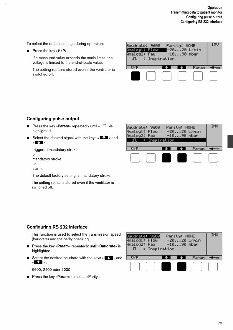
To select the default settings during operation:
Press the key »****/P«.
If a measured value exceeds the scale limits, thevoltage is limited to the end-of-scale value.
The setting remains stored even if the ventilator isswitched off.
Configuring pulse output
Press the key »Param« repeatedly until » «ishighlighted.
Select the desired signal with the keys » « and » «:
triggered mandatory strokeormandatory strokeoralarm.
The default factory setting is: mandatory stroke.
The setting remains stored even if the ventilator isswitched off.
Configuring RS 232 interface
This function is used to select the transmission speed(baudrate) and the parity checking.
Press the key »Param« repeatedly until »Baudrate« ishighlighted.
Select the desired baudrate with the keys » « and» « :
9600, 2400 oder 1200
Press the key »Param« to select »Parity«.
73
OperationTransmitting data to patient monitor
Configuring pulse outputConfiguring RS 232 interface

Select the desired parity with the keys » « and » «:
NONEorEVEN orODD
When using a printer, select »NONE«.
The default factory settings are:
Baudrate: 9600Parity: NONEStop bits: 1 (fixed)Data bits: 8 (fixed)
Exit from the menu:
Press the key » «.
The settings remain stored even if the ventilator is switched off.
Setting the printer
The printer must be configured as follows:
Baudrate: same as Babylog 8000 plusParity: noneData bits: 8Handshake mode: XON/XOFF
Alternate control sequence mode
OperationConfiguring RS 232 interfaceSetting the printer
74
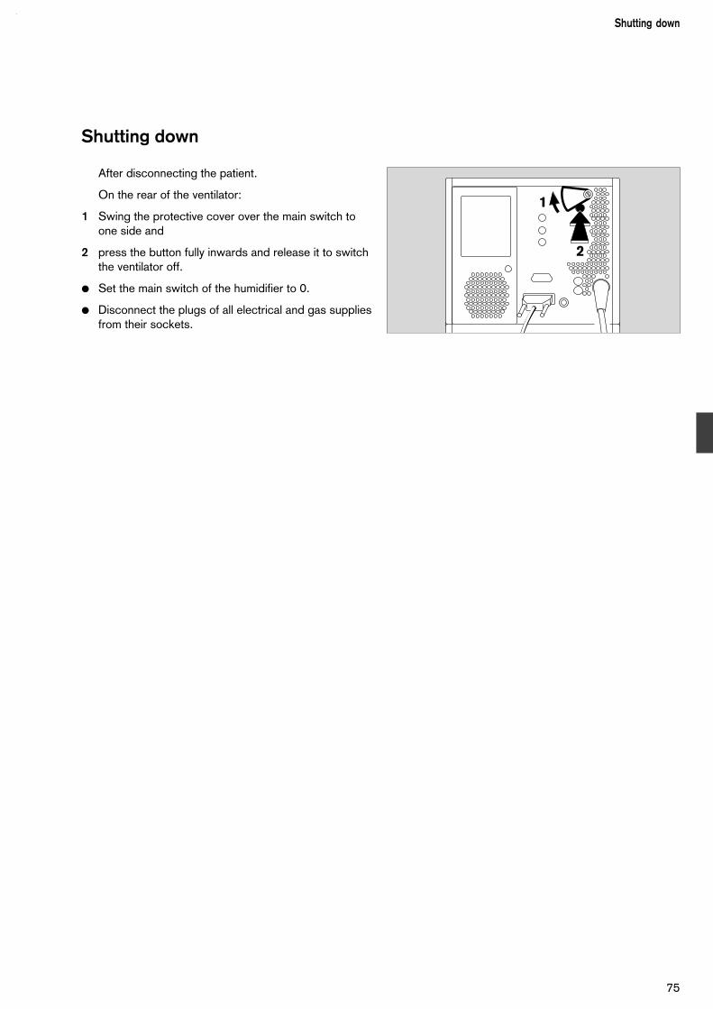
Shutting down
After disconnecting the patient.
On the rear of the ventilator:
1 Swing the protective cover over the main switch toone side and
2 press the button fully inwards and release it to switchthe ventilator off.
Set the main switch of the humidifier to 0.
Disconnect the plugs of all electrical and gas suppliesfrom their sockets.
75
Shutting down
1
2

76

Contents
Fault – Cause – Remedy......................................................................... 78
77
Fault – Cause – RemedyContents
Fault – Cause – Remedy

Message Cause Remedy
Airway pressure highExp. valve opened
Pressure increase in hose system;expiratory valve has been opened torelieve the system.Equipment malfunction (patientsystem)
Check the hose system.Replace the patient system.
Call DrägerService.
Airway pressure highInspiration cancelled
Pressure increase in hose system;mechanical inspiration has beenshortened to relieve the system.Equipment malfunction (patientsystem)
Check the hose system.Replace the patient system.
Call DrägerService.
Airway pressure low Leak or disconnection
Insp. or exp. flow set too low
Check that hose connections are tight.Increase the flow.
Apnoea Patient's spontaneous breathing hasceased.
Ventilate with supervision.
Calibrate flow sensor ! Calibration of the flow sensor isrequested each time the unit isswitched on or after a power failure.
Without calibration, no flow can bemeasured.
Press key »OK« and calibrate the flowsensor (page 26).
To continue operation without flowmeasurement, simply press »OK«.
Check PEEP setting ! For high-frequency ventilation, therotary knob »PEEP/CPAP« determinesthe mean value of the airway pressure.
After completion of high-frequencyventilation, set PEEP to the desiredvalue with the rotary knob»PEEP/CPAP«.
Fault in rotary knob Equipment fault Call DrägerService.
FiO2 high Fault in FiO2 measurementorfault in mixer function
Calibrate O2 sensor manually (page 25).Call DrägerService.
FiO2 low Fault in FiO2 measurementorfault in mixer function
Calibrate O2 sensor manually (page 25).Call DrägerService.
Fault – Cause – Remedy
78
Fault – Cause – Remedy
The Babylog 8000 plus classifies the messages in three levels of urgency:
Alarm messages – Caution messages – Advisory messages
The messages are listed in alphabetical order in the following table.
The table is intended to help you to find the cause for an alarm message and to rectify the related condition.

Message Cause Remedy
Flow measurement disturbed VG uses Pinsp, Check set value !
Volume guarantee VG stops becausethe flow sensor is defective or discon-nected; flow-measurement malfunction
Replace the flow sensor.Connect the cable.Set Pinsp to a suitable value.
Flow measurement disturbedMeasurement switched off
Flow sensor faulty or disconnected.Malfunction.Cable faulty.
Connect the flow sensor or cable.Calibrate the flow sensor (page 26).Replace the flow sensor (page 22).Replace the cable.
Flow sensor dirty ?Please clean sensor!
Water or secretion in the flow sensor Replace sensor insert.
Frequency high ! HyperventilationSelf-triggering
Adjust the frequency.Increase the trigger threshold.
Hose kinked ? Ventilation hose kinked or blocked orcondensate in the hose.
Internal diameter of ventilation hosestoo small.
Check and clear the hose system.
Use a suitable hose system.
I : E maximum 3 : 1! The rotary knobs for TI and TE havebeen set to a TI:TE ratio greater than3:1. The setting is limited to 3:1.
Check the settings for TI and TE andcorrect if necessary.
IRV ! The rotary knobs for TI and TE havebeen set to a TI:TE ratio greater than1:1 (Inversed Ratio Ventilation)
Press »OK« or check the settings forTI and TE and correct if necessary.
Leak in hose system ?Check setting !
Leakage or disconnection.Pinsp set too high.
Check the hose system for leaks.Check the Pinsp setting.
Loss of stored data Equipment malfunction (e.g. after apower failure).
Enter the lost settings again orcall DrägerService.
Machine fault xyzxyz = error code
Equipment malfunction. Call DrägerService.
Medical air low Air supply pressure too low Ensure that the pressure is above 3 bar.
Medical air supply pressure measurement disturbed
Pressure sensor or pressure reductionvalve faulty.
Call DrägerService.
MV high Lung compliance has increased.Resistance has decreased.Hyperventilation.Equipment malfunction.
Check the ventilation settings andcorrect if necessary.
Call DrägerService.
MV low The lung compliance has decreased.Resistance has increased.Spontaneous breathing intermittent orweaker.Equipment malfunction.Tube leakage too high.
Check the ventilation settings andcorrect if necessary.
Call DrägerService.
Fault – Cause – Remedy
79
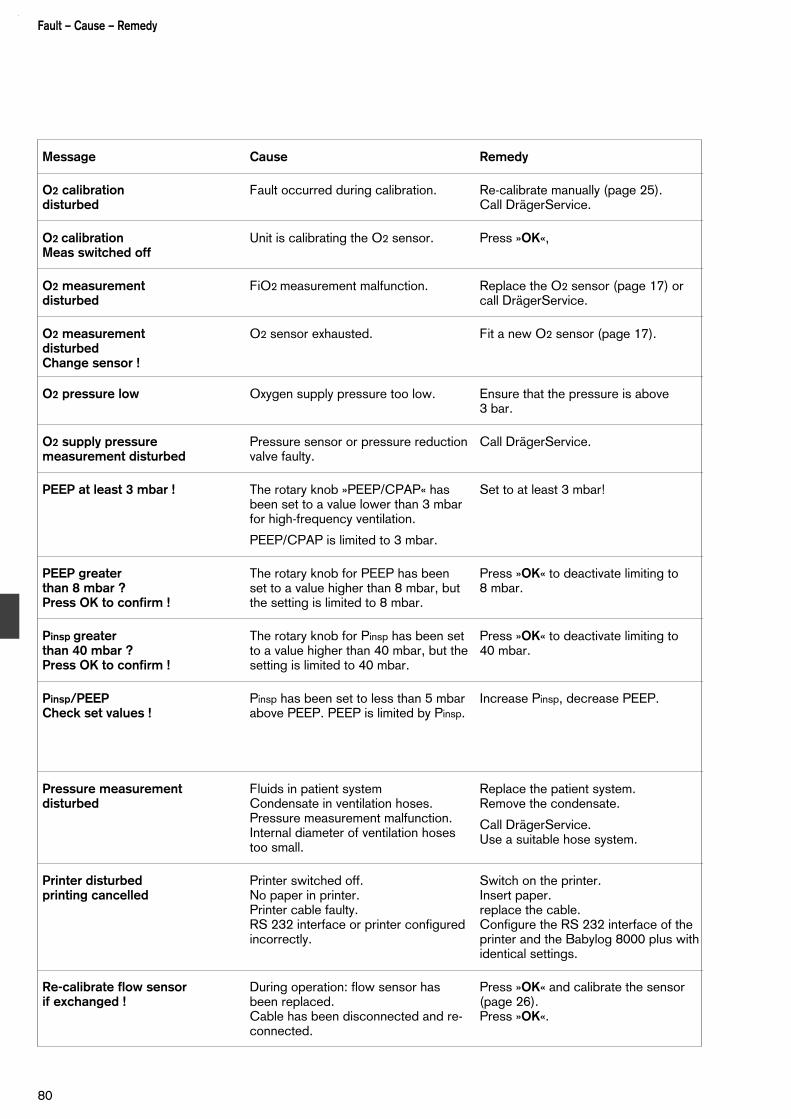
Fault – Cause – Remedy
80
Message Cause Remedy
O2 calibrationdisturbed
Fault occurred during calibration. Re-calibrate manually (page 25).Call DrägerService.
O2 calibrationMeas switched off
Unit is calibrating the O2 sensor. Press »OK«,
O2 measurementdisturbed
FiO2 measurement malfunction. Replace the O2 sensor (page 17) orcall DrägerService.
O2 measurementdisturbed Change sensor !
O2 sensor exhausted. Fit a new O2 sensor (page 17).
O2 pressure low Oxygen supply pressure too low. Ensure that the pressure is above3 bar.
O2 supply pressure measurement disturbed
Pressure sensor or pressure reductionvalve faulty.
Call DrägerService.
PEEP at least 3 mbar ! The rotary knob »PEEP/CPAP« hasbeen set to a value lower than 3 mbarfor high-frequency ventilation.
PEEP/CPAP is limited to 3 mbar.
Set to at least 3 mbar!
PEEP greater than 8 mbar ?Press OK to confirm !
The rotary knob for PEEP has beenset to a value higher than 8 mbar, butthe setting is limited to 8 mbar.
Press »OK« to deactivate limiting to 8 mbar.
Pinsp greater than 40 mbar ?Press OK to confirm !
The rotary knob for Pinsp has been setto a value higher than 40 mbar, but thesetting is limited to 40 mbar.
Press »OK« to deactivate limiting to 40 mbar.
Pinsp/PEEPCheck set values !
Pinsp has been set to less than 5 mbarabove PEEP. PEEP is limited by Pinsp.
Increase Pinsp, decrease PEEP.
Pressure measurementdisturbed
Fluids in patient systemCondensate in ventilation hoses.Pressure measurement malfunction.Internal diameter of ventilation hosestoo small.
Replace the patient system.Remove the condensate.
Call DrägerService.Use a suitable hose system.
Printer disturbedprinting cancelled
Printer switched off.No paper in printer.Printer cable faulty.RS 232 interface or printer configuredincorrectly.
Switch on the printer.Insert paper.replace the cable.Configure the RS 232 interface of theprinter and the Babylog 8000 plus withidentical settings.
Re-calibrate flow sensorif exchanged !
During operation: flow sensor hasbeen replaced.Cable has been disconnected and re-connected.
Press »OK« and calibrate the sensor(page 26).Press »OK«.

Message Cause Remedy
Tube obstructed ? Tube kinked or blocked. Clear the tube.
VT lowCheck settings !
Tidal volume does not reach the setvalue.
Increase the flow * insp.Increase the inspiration time, possiblyincrease Pinsp.
Fault – Cause – Remedy
81

82

Contents
Care........................................................................................................ 84Stripping down.........................................................................................84Disinfecting/cleaning/sterilising.................................................................84
Checking readiness for use....................................................................87
Maintenance intervals............................................................................. 92
83
CareContents
Care

Care
Stripping down
Ventilation hoses
Empty the water traps.
Disconnect the plugs of the flow-sensor cable fromthe insert and the socket on the rear of the ventilator.
Pull the insert out of the flow sensor:
Press the buttons on both sides and simultaneouslypull the insert out of the Y-piece.
Remove the hoses from the hose holder of theincubator.
Remove the hoses from the sleeves on the ventilatorand on the humidifier module.
Remove the water trap and the Y-piece and pull thecollecting jar from the water trap.
Removing the expiration valve
1 Lift the locking lever upwards.
2 Pull the expiration valve out forwards.
Disinfecting/cleaning/sterilising
Use surface disinfectants for disinfection. For reasonsof material compatibility, suitable disinfectants arethose on the based on:
– aldehydes,
– alcohols and
– quaternary ammonium compounds.
The following are not suitable:
– compounds containing phenol.
– compounds which release halogens,
– strong organic acids,
– compounds which release oxygen or
– sterilisation with ethylene oxide.
CareStripping downDisinfecting/cleaning/sterilising
84
D Babylog 8000 plus
1
2

For users in the Federal Republic of Germany, werecommend the use of disinfectants shown in thecurrent DGHM (Deutsche Gesellschaft für Hygieneund Mikrobiologie) list.The DGHM list (available from mhp-Verlag,Wiesbaden) also shows the effective ingredients ofeach disinfectant. In countries where the DGHM list is unknown, theabove recommendations apply.
Basic Babylog 8000 plus unit, trolley, flow-sensorcable and gas connection hoses
Disinfect by wiping with, for example, Buraton 10 F(Messrs. Schülke & Mayr, Norderstedt).Observe the manufacturer's instructions for use.
Flow-sensor insert
Do not use a cleaning/disinfecting machine.Do not clean with compressed air, water jet,brush, etc., since this will destroy the thin wires inthe flow sensor.
Dried mucus will shorten the service life of the flowsensor; for this reason:
disinfect the sensor immediately after use in a bathcontaining, for example, Gigasept FF (Messrs.Schülke & Mayr, Norderstedt).Observe the manufacturer's instructions for use.
Then rinse the insert by carefully moving it to and froin a bath of distilled water. Thoroughly shake out anyremaining water.
Then:
sterilise in hot steam at 130 °C to 140 °C.
Expiration valve, ventilation hoses, Y-piece(without flow sensor), catheter cone
Clean and disinfect with moist heat (for example: 93 °C/10 min) in a cleaning anddisinfecting machine, using only a detergent.
85
CareDisinfecting/cleaning/sterilising

After cleaning
Sterilise in hot steam at 130 °C to 140 °C.
Always sterilise the expiration valve in order to removeany water remaining in the ducts and control lines.
Installing the flow-sensor insert
1 Align the two marks and slide the insert into the Y-piece until it locks into position.
Insert the plug into the sensor.
Assemble the equipment as described in"Preparation" (pages 20 to 22).
After switching on:
Calibrate the flow sensor (page 25).
Check readiness for use (page 87).
CareDisinfecting/cleaning/sterilising
86
1

Checking readiness for use
This must be done each time the unit is assembled.
Assemble the equipment completely (pages 20 to 22).
After switching on, calibrate the flow sensor (page 25).
Connecting the test lung
The test lung consists of a bellows simulatingcompliance (about 0.5 mL/mbar) and a CH 12tracheal tube about 165 mm long, with connector, for simulation of airway resistance.
Testing the mains failure alarm
Disconnect the mains plug from the from the mainssupply socket.
1 Switch on the ventilator by pressing the main switchon the rear of the unit until it locks into position.A continuous tone must sound at a constant level forabout 20 seconds. If this does not happen, charge the battery (see "Before using for the first time" on page 23).
On the rear of the unit:
2 Swing the protective cover of the main switch to oneside.
1 Fully depress the main switch and release it to switchthe ventilator off. The continuous tone ceases.
Re-insert the mains plug into the mains supply.
87
CareChecking readiness for use
Connecting test lungTesting mains failure alarm
2
1

Testing gas failure alarm
Switch on the ventilator by pressing the main switchon the rear of the unit until it locks into position.
Switch on IPPV/IMV (page 36).
Set lower alarm limit MV to 0 and upper alarmlimit MV to 15 l/min.
1 Turn the rotary knob »O2-Vol%« to 60 %.
Remove the oxygen connection hose from the walloutlet socket.
2 The red alarm lamp must blink and the alarm mustsound.
Display:
Re-insert the oxygen connection hose into the walloutlet socket.
2 The red alarm lamp is extinguished, the alarmmessage disappears and the alarm tone is switchedoff.
Remove the medical air connection hose from the walloutlet socket.
Display:
2 The red alarm lamp must blink and the alarm mustsound.
Re-insert the medical air connection hose into the walloutlet socket.
2 The red alarm lamp is extinguished, the alarmmessage disappears and the alarm tone is switchedoff.
CareChecking readiness for useTesting gas failure alarm
88
2
1

Testing IPPV
Switch on IPPV/IMV (page 36).
Set the following rotary knobs (where the green LEDsare lit) as follows:
1 »O2-Vol%« to 21.
2 »Insp. Flow **** « to 10.
3 »TI« to 0.4. »TE« to 0.6.
4 »Pinsp« to 20.
5 »PEEP/CPAP« to 0.
In the monitoring menu, press the keys »Meas« and »Paw«.
Display (example):
The displayed values must lie within their permissibleranges, as follows:
Peak 18 to 22 mbarMean 6 to 10 mbarPEEP –1.5 to 1.5 mbar
Testing PEEP 6 Set the rotary knob »PEEP/CPAP« to 10.
Confirm this setting:
7 Press the key »OK«.
Display (example):
The displayed values must lie within their permissibleranges, as follows:
Peak 18 to 22 mbarMean 12 to 16 mbarPEEP 8 to 12 mbar
1 3 3
2 4 5
89
CareChecking readiness for use
Testing IPPVTesting PEEP
7
6

Testing alarm limits
Alarm limits for apnoea:
1 Switch on CPAP (page 42).
After not more than 30 seconds:
2 The red alarm lamp must blink and the alarm mustsound.
Display (example):ApnoeaorMV low
Alarm limits for airway pressure:
3 Switch on IPPV/IMV (page 42).
4 Kink the expiration hose:
2 The red alarm lamp must blink and the alarm mustsound.
Display (example):Hose kinked?orAirway pressure high
4
3
2
1
CareChecking readiness for useTesting alarm limits
90
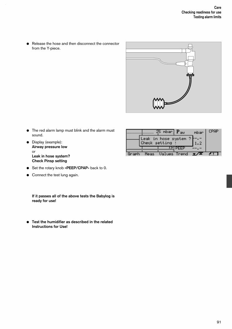
Release the hose and then disconnect the connectorfrom the Y-piece.
The red alarm lamp must blink and the alarm mustsound.
Display (example):Airway pressure loworLeak in hose system?Check Pinsp setting
Set the rotary knob »PEEP/CPAP« back to 0.
Connect the test lung again.
If it passes all of the above tests the Babylog isready for use!
Test the humidifier as described in the relatedInstructions for Use!
91
CareChecking readiness for use
Testing alarm limits

Maintenance intervals
Always clean and disinfect the unit and/or its components beforemaintenance and before sending it/them in for repair!
O2 sensor replace in the case of a fault message (page 17).
Cooling-air filter clean or replace every 4 weeks (page 93);to be replaced at least once per year.
Lip seals of the to be replaced at least every 2 years by trained connecting plate service personnelbehind patient system
NiCd battery for to be replaced at least every 2 years by trainedmains failure alarm service personnel (see page 93 for disposal).
Time-keeper RAM to be replaced at least every 4 years by trained service personnel (see page 93 for disposal).
Inspection and to be carried out every 6 months by trained service* service personnel
General overhaul to be carried out every 6 months by trained of pressure service personnelreduction valves
For units with LC displays:
If the glass of the LC display is broken, a chemical liquid can leak out.Avoid skin contact. If affected, wash skin areas immediately with soapand water!
_____________
* Definitions:Inspection = examination of the actual conditionService = measures to maintain the specified conditionRepair = measures to restore the specified conditionMaintenance = inspection, service and repair
CareMaintenance intervals
92

Replacing the cooling-air filter Pull the cooling-air filter out of its holder on the rear of
the ventilator.
Use a new filter or wash the old filter in warm waterand detergent and dry thoroughly.
Insert the filter in its holder without folding it.
Disposal of batteries and O2 sensors
Batteries, and O2 sensors:
Do not incinerate batteries or O2 sensors as they mayexplode.
Do not open them as they contain corrosivesubstances!
Do not attempt to charge dry batteries.
Batteries and O2 sensors should be regarded as specialwaste:
Dispose of them in accordance with the localregulations for waste disposal.
Exhausted O2 sensors can be returned to Dräger Medizintechnik GmbH.
Disposal of the ventilator
– at the end of its service life
The Babylog 8000 plus 5.n may be returned to Dräger Medizintechnik GmbH for suitable disposal.
93
Maintenance intervalsReplacing cooling-air filter
Disposal of batteries and O2 sensorsDisposal of ventilator

94

Contents
Control panel........................................................................................... 96Display panel............................................................................................97Connections.............................................................................................98Rear side..................................................................................................99
95
What's WhatContents
What's What
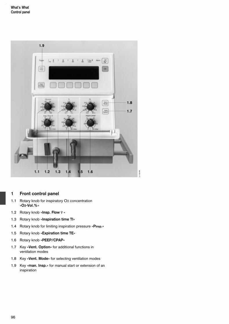
1 Front control panel
1.1 Rotary knob for inspiratory O2 concentration »O2-Vol.%«
1.2 Rotary knob »Insp. Flow * «
1.3 Rotary knob »Inspiration time TI«
1.4 Rotary knob for limiting inspiration pressure »Pinsp.«
1.5 Rotary knob »Expiration time TE«
1.6 Rotary knob »PEEP/CPAP«
1.7 Key »Vent. Option« for additional functions inventilation modes
1.8 Key »Vent. Mode« for selecting ventilation modes
1.9 Key »man. Insp.« for manual start or extension of aninspiration
What's WhatControl panel
96
1.9
1.1 1.2 1.3 1.4 1.5 1.6
1.8
1.7
2-11
24-9
6

2 Display panel
2.1 Key for selecting the calibration and configurationmenus
2.2 Yellow LED »Trigger« lights when inspiration isstarted by the trigger
2.3 Screen for display of settings and measured values
2.4 Bargraph display for the airway pressure Paw
2.5 Red alarm lamp; blinks to draw attention to an alarmor caution message displayed on the screen
2.6 Key »g « for suppressing the alarm tone for about2 minutes
2.7 Key »OK« for acknowledging messages and fortesting the LEDs and the alarm tone
2.8 Menu keys
97
What's WhatDisplay panel
2.1
2.8
2.6
2.7
2.3 2.4 2.5
2-11
23-9
6
2.2

3 Connections
3.1 Silencer
3.2 Locking lever for expiration valve
3.3 Expiration nozzle
3.4 Inspiration nozzle
What's WhatConnections
98
3.1 3.2 3.3 3.4
2-11
23-9
6

4 Back of unit
4.1 Main switch
4.2 Mains fuses (2x)
4.3 Potential equalisation stud
4.4 Oxygen connection
4.5 Medical-air connection
4.6 Socket for flow-sensor cable
4.7 Cooling-air filter for fan
4.8 Connectors for optional interfaces
99
What's WhatRear side
4.5 4.4
4.6
4.1
4.24.2
4.3
4.7 4.8
2-11
25-9
6

100

Contents
Technical Data...................................................................................... 102Equipment parameters........................................................................... 103Measurement functions – ranges and accuracy...................................... 103Alarm criteria..........................................................................................106Operating data....................................................................................... 107
101
Technical DataContents
Technical Data
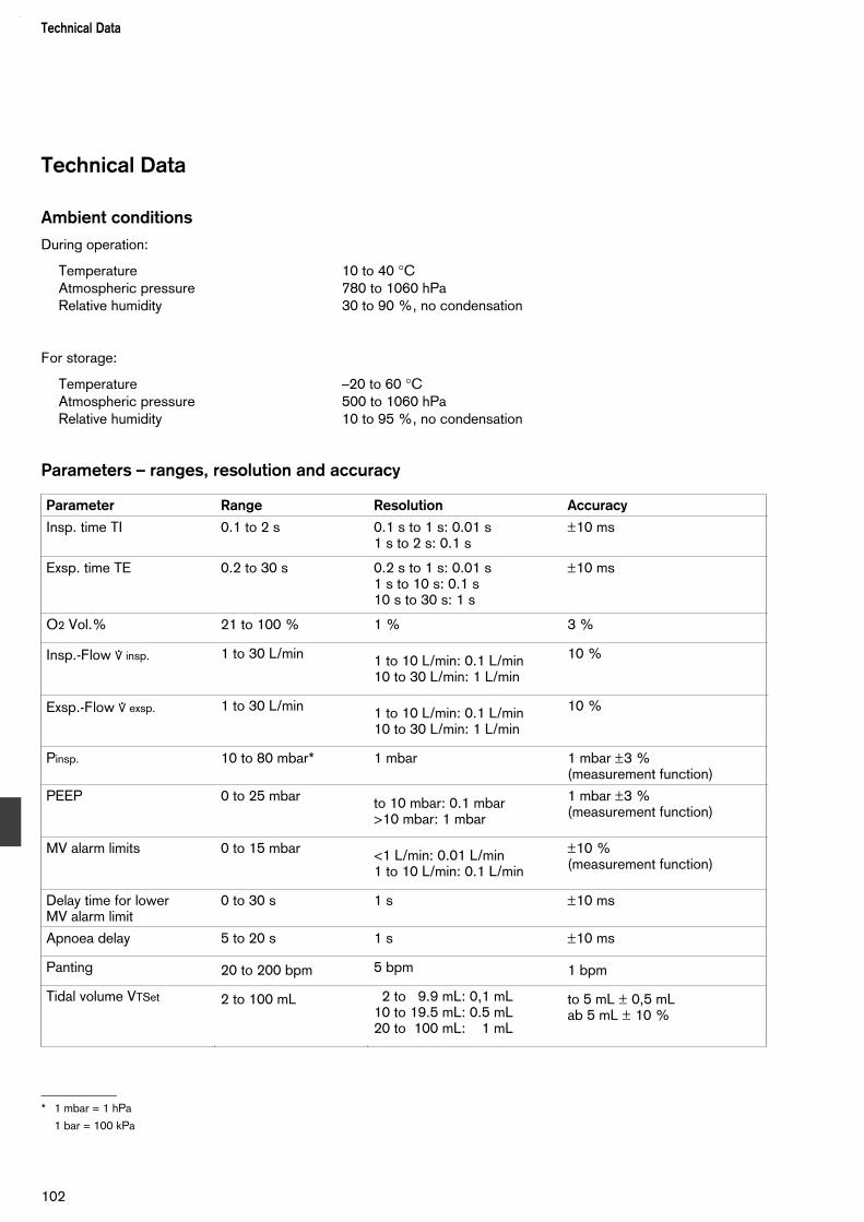
Technical Data
Ambient conditions
During operation:
Temperature 10 to 40 °CAtmospheric pressure 780 to 1060 hPaRelative humidity 30 to 90 %, no condensation
For storage:
Temperature –20 to 60 °CAtmospheric pressure 500 to 1060 hPaRelative humidity 10 to 95 %, no condensation
Parameters – ranges, resolution and accuracy
_____________
* 1 mbar = 1 hPa
1 bar = 100 kPa
Technical Data
102
Parameter Range Resolution Accuracy
Insp. time TI 0.1 to 2 s 0.1 s to 1 s: 0.01 s1 s to 2 s: 0.1 s
±10 ms
Exsp. time TE 0.2 to 30 s 0.2 s to 1 s: 0.01 s1 s to 10 s: 0.1 s10 s to 30 s: 1 s
±10 ms
O2 Vol.% 21 to 100 % 1 % 3 %
Insp.-Flow * insp. 1 to 30 L/min 1 to 10 L/min: 0.1 L/min10 to 30 L/min: 1 L/min
10 %
Exsp.-Flow *exsp. 1 to 30 L/min 1 to 10 L/min: 0.1 L/min10 to 30 L/min: 1 L/min
10 %
Pinsp. 10 to 80 mbar* 1 mbar 1 mbar ±3 % (measurement function)
PEEP 0 to 25 mbar to 10 mbar: 0.1 mbar>10 mbar: 1 mbar
1 mbar ±3 % (measurement function)
MV alarm limits 0 to 15 mbar <1 L/min: 0.01 L/min1 to 10 L/min: 0.1 L/min
±10 % (measurement function)
Delay time for lower MV alarm limit
0 to 30 s 1 s ±10 ms
Apnoea delay 5 to 20 s 1 s ±10 ms
Panting 20 to 200 bpm 5 bpm 1 bpm
Tidal volume VTSet 2 to 100 mL 2 to 9.9 mL: 0,1 mL10 to 19.5 mL: 0.5 mL20 to 100 mL: 1 mL
to 5 mL ± 0,5 mLab 5 mL ± 10 %

Equipment parameters
Principle of operation Babylog 8000 plus ventilates on the continuous-flow principle with time control and and is pressure limited.Oxygen is added to the air with an integrated air-oxygen mixer.
Control principle Continuous flow, expiration valve, pressure-limited, time-controlled
Trigger sensitivity 1 to 10 corresponds to about 0.02 to 3 mL
Trigger delay time Typically 40 to 60 ms(time from the start of [see explanation on page 124]spontaneous inspiration to the start of a synchronised mandatory ventilation stroke)
Pos. end exp. pressure (PEEP) orcontinuous pos. airway pressure (CPAP) 0 to 25 mbar
System compliance with hose systembut without humidifier <0.6 mL/mbar
System resistance at 30 L/min <20 mbar/L/sinspiratory resistance <12 mbar/L/sexpiratory resistance <8 mbar/L/s
Use other hose systems only if their resistance does not exceed the specified values since the measurement of theairway pressure may otherwise be affected!
Measurement functions – ranges and accuracyAirway pressure
Sensor Two differential pressure sensors within the ventilator measure the pressures, relative to the atmospheric pressure, at the inspiration and expiration connectors of the hose system. The pressure at the Y-piece is calculated from these two values (see the explanation on page 122).
Measuring range –10 to 100 mbar
Zero-point error ±1.0 mbar
Amplification error ±3 % of measured value
Measurement conditions according to EN 794-1, para. 51.7
Display parametersAll parameters are displayed digitally or graphically on screen.
103
Technical Data
Parameter Range Resolution
Peak 0 to 99 mbar 0 to 9.9 mbar: 0.1 mbar10 to 99 mbar: 1 mbar
PEEP 0 to 99 mbar 0 to 9.9 mbar: 0.1 mbar10 to 99 mbar: 1 mbar
Pmean 0 to 99 mbar 0 to 9.9 mbar: 0.1 mbar10 to 99 mbar: 1 mbar
Airway pressure (t),bargraph display
–10 to 80 mbar 2 mbar
Airway pressure (t),screen display
–10 to 100 mbar –2.5 to 25 mbar: 0.5 mbar–5 to 50 mbar: 1 mbar–10 to 100 mbar: 2 mbar

Flow and volume
Sensor Hot-wire anemometer between Y-piece and tube connector
Gas composition Medical gas according to the selected oxygen air mix
Reference conditions can be switched between– NTPD (normal temperature 20 °C, atmospheric pressure
1013 hPa, dry gas) and– BTPS (body temperature 37 °C, ambient pressure, gas
saturated with moisture)
Flow measurement range 0.2 L/min to 30 L/min3 dB cut-off frequency 28 Hz
Measuring accuracy for expiratory tidal volume(without expiratory leakage)
Measuring conditions in accordance with EN 794-1, Section 51.106Measuring range 0 to 999 mLMeasuring error up to 5 mL 0.5 mLMeasuring error above 5 mL 10 % of measured value
Display parametersAll parameters are displayed numerically or graphically on the screen.
* 1 bpm = 1 breath per minute
Technical Data
104
Parameter Range Resolution
VT 0 to 999 mL 0 to 9.9 mL: 0.1 mL10 to 99 mL: 1 mL
MV 0 to 30 L/min 0 to 0.99 L/min: 0.01 L/min1 to 9.9 L/min: 0.1 L/min10 to 30 L/min: 1 L/min
Leakage 0 to 100 % 0 to 10 %: 10 %10 to 100 %: 1 %
Spontaneous component of MV 0 to 100 % 1 %
DCO2 0 to 999 mL2/s 1 mL2/s
Flow curve –20 to 20 L/min –2.5 to 2.5 L/min: 0.1 L/min–5 to 5 L/min: 0.2 L/min–10 to 10 L/min: 0.4 L/min–20 to 20 L/min: 0.8 L/min
Frequency 0 to 9.9 bpm 10 to 999 bpm*
0.1 bpm1 bpm
RVR 0 to 1000 bpm/mL 0.1 bpm/mL
Sensor type Dead space volume (without tube) Resistance at 30 L/min
Y-piece with flow sensor 84 10 185 1.7 mL ≤12 mbar
Flow sensor ISO 15 84 11 130 0.9 mL ≤11 mbar
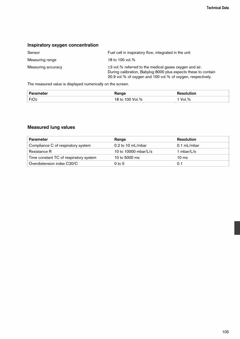
Inspiratory oxygen concentration
Sensor Fuel cell in inspiratory flow, integrated in the unit
Measuring range 18 to 100 vol.%
Measuring accuracy ±3 vol.% referred to the medical gases oxygen and air.During calibration, Babylog 8000 plus expects these to contain 20.9 vol.% of oxygen and 100 vol.% of oxygen, respectively.
The measured value is displayed numerically on the screen.
Measured lung values
105
Technical Data
Parameter Range Resolution
FiO2 18 to 100 Vol.% 1 Vol.%
Parameter Range Resolution
Compliance C of respiratory system 0.2 to 10 mL/mbar 0.1 mL/mbar
Resistance R 10 to 10000 mbar/L/s 1 mbar/L/s
Time constant TC of respiratory system 10 to 5000 ms 10 ms
Overdistension index C20/C 0 to 5 0.1

Alarm criteria
Insp. O2 concentrationAn alarm is generated if the measured inspiratory O2 concentration FiO2 ismore than 4 vol.% above or below the set value for longer than 25 seconds.
DisconnectionA disconnection or a major leak in the hose system means that no (or an in-sufficient) ventilation pressure is generated. Detection is therefore achievedby checking whether a minimum pressure which depends on the operatingmode and the PEEP and Pinsp settings is reached. An alarm is generated if,in ventilation modes IPPV/IMV, SIPPV and SIMV, the airway pressure doesnot lie above the minimum pressure PEEP + (Pinsp-PEEP)/4 for at least0.025 seconds in each ventilation cycle.
Inspiratory pressure highDuring mandatory inspiration, the airway pressure should not exceed the setpressure limits. An excess pressure of up to 5 mbar is tolerated so thatcoughing, for example, does not immediately generate an alarm. Above thealarm threshold Pinsp+5 mbar, the pressure-time integral of the excess valueis calculated and an alarm is generated if this value exceeds 0.33 mbar.Mandatory inspiration is terminated at the same time. Example: the airway pressure rises to 6 mbar above the pressure limit Pinspand then remains constant. The alarm is generated after 0.33 s. If, after the alarm, the pressure-time integral increases further and rises above0.58 mbar·s, ventilation is terminated and the hose system is vented.
CPAP pressure highAn alarm is generated in ventilation mode CPAP and in the expiration phasesof the mandatory ventilation modes if the airway pressure lies above thethreshold PEEP/CPAP+4 mbar for more than 5 seconds. At the same time,the hose system is vented.If the airway pressure rises above PEEP/CPAP+25 mbar, the alarm isgenerated after 0.3 seconds.
CPAP pressure lowAn alarm is generated if the airway pressure drops below PEEP/CPAP–2 mbar and the pressure-time integral exceeds 6 mbar·s.
Tube blockedA blocked or kinked endotracheal tube allows no breathing gas to flow, andthis situation is detected by measuring the flow.An alarm is generated if no flow is measured during a complete ventilationcycle in any mandatory ventilation mode.
Ventilation hose kinkedThis situation is detected by measuring the airway pressure at the inspirationand expiration connectors of the ventilator. If a ventilation hose is blocked orkinked, the airway pressure at the inspiration connector rises and the pres-sure difference between the two connectors is considerably greater than innormal operation.An alarm is generated if the pressure difference exceeds 8 mbar+0.6 Insp.Flow (in L/min). At the same time, the hose system is vented.
106
Technical Data

Tidal volume VT lowThis is detected when the VG volume regulation function cannot apply the settidal volume. An alarm is generated if VT is less than 90 % VTset or VTset-0.5 mL, whichever is lower. The reasons for this may be:1. that PInsp is set too low and the ventilation pressure is insufficient to
generated the desired VT or
2. that there is no plateau in the inspiration because the inspiratory flow is settoo low or the inspiration time TI is set too short.
The alarm is delayed by the time "Alarm delay".
Minute volume MVAn alarm is generated if the measured minute volume lies outside the adjus-table alarm limits. If, however, the volume drops below the lower alarm limit,the alarm is delayed by a time which can be adjusted between 0 and 30 seconds. Brief interruptions of the breathing can thus be tolerated withoutan immediate alarm. The alarm limits can be set between 0 and 15 L/min, butthe upper limit must always be set higher than the lower limit.
ApnoeaAn alarm is generated if the ventilator does not detect any ventilation for aperiod longer than the set apnoea time, where "ventilation" means a minimumtidal volume. This must be at least 0.6 mL for mandatory ventilation, at least0.4 mL for spontaneous breathing and at least 0.2 mL for high-frequencyventilation. The apnoea time can be set in the range 5 s to 20 s.
PantingAn alarm is generated if the measured breathing frequency is greater than thecurrent setting of the adjustable panting frequency limit.
Safety principleThe Babylog 8000 plus is a software-controlled ventilator. Its safety conceptis based on the use of two microprocessor systems which operate indepen-dently of each other, each monitoring the functions of the other. The measu-ring and alarm functions required for this are duplicated.
Operating data
Mains supply voltage Range: 100/110/127 V ±10 % 230/240 V ±10 % switchable50/60 Hz
Current consumptionat 230 V 0,6 A at 110 V 1,3 A
Power consumption approx. 140 W
Fuses Range 100 V to 127 V T4A H 250V IEC 127-2/ VRange 230 V to 240 V T4A H 250V IEC 127-2/ V
107
Technical Data
Gas supplyO2 operating pressure 3 bar –10 % to 6 bar +10 % O2 connection thread M12 x 1, femaleAir operating pressure 3 bar –10 % to 6 bar +10 % Air connection thread M20 x 1.5, male
The gases must be dry and free of oil and dust.
Gas consumption for control approx. 3.0 mL/min airGas consumption for ejector 10 L/min Total gas consumption max. 43 L/min air or O2
Sound pressure(free-field measurement over reflecting surface)
Protection classification Type BF bodyfloating = EN 60601-1, section 19, tab. 4: max. permissive earth leakage current 0.5 mA
Dimensions (W x H x D)Basic unit 212 x 280 x 390 mm Unit with trolley 700 x 1335 x 700 mm
WeightBasic unit approx. 14.5 kg
Electromagnetic compatibility EMC Tested to EN 60601-1-2
Classification according to Class II bDirective 93/42/ECAppendix IX
UMDNS-Code 17 – 361Universal Medical DeviceNomenclature System
Analogue and digital interfaces (optional)
All inputs and outputs of the analogue and digital interfaces are electricallyisolated from the electronics of the ventilator. The electric strength is 2.5 kV.
Analog1 and Analog2The outputs are resistant to short circuits.The output voltages are generated by one12-bit D/A converter, followed by a low-passfilter, for each interface.
Connection plug SMB-Subclic
108
Technical Data

Signal delay Electronic filter circuits in the Babylog 8000 plus delay the signals for airway pressure and flow by about 15 ms with respect to the sensor signals.This delay must be taken into account when measuring with a separate measu-ring device and comparing its output with the analogue output of the Babylog 8000 plus.
Output resistance ≈ 10 kΩ
Pulse output
The output is resistant to short circuits.
H-level voltage 5 V ±0.5 V unloaded
L-level voltage 0 V ±0.5 V unloaded
Output resistance <5 kΩ
Connection plug SMB-Subclic
RS 232 interfaceLevels in accordance with DIN 66020
Pin assignments of printer cable 83 06 489
Pin assignments of monitor cable 83 06 488
109
Technical Data
GND GND
Babylog 8000 plusPin5
2
3
RxD TxD
TxD RxD
HP ThinkjetPin7
2
3
Steckergehäuse25pol Sub D Stecker
9pol Sub DStecker
GND GND
Babylog 8000 plus
5
2
3
RxD TxD
TxD RxD
Monitor
5
3
2
9pol Sub DStecker
9pol Sub DBuchseSteckergehäuse
plug plugPlug case
plug socketPlug case

110

Contents
Pneumatic circuits................................................................................ 112
Ventilation mode...................................................................................115
Monitoring functions.............................................................................122
Explanation of abbreviations................................................................ 128
Explanation of symbols.........................................................................129
111
DescriptionContents
Description

Block diagram of the pneumatic circuit(simplified)
1 Sintered filter
2 Non-return valve
3 Pressure regulator
4 Absolute-pressure sensor
5 Solenoid valve of mixer and dosing unit
6 Flow adjuster of mixer and dosing unit
7 Solenoid changeover valve
8 Solenoid valve
9 Solenoid valve
10 Non-return valve
11 Filter
12 Pneumatic control valve
13 Flow adjuster
14 O2 sensor
15 Pneumatic control valve
16 Pneumatic safety valve
17 Relative-pressure sensor
18 Electrical PEEP control valve
19 Safety valve
20 Expiration valve
21 Bactericidal labyrinth
22 Relative-pressure sensor
23 Solenoid valve
24 Ejector
DescriptionPneumatic circuits
112
E
E
P
P
EP
EP
EO2
1
Air
O2
Inspiration
Exspiration
2 3
1 2 3
4
4
56
56
10
11 13 14
7
8 9
23 18
20
21
22
17
24
19
12
16
15

Gas supply
The compressed gases air and oxygen are connected viathe filters 1 and the non-return valves 2 to the pressureregulators 3, which maintain a constant system pressurefor each gas.
The non-return valves 2 prevent gas from flowing backinto the central gas supply system.
The absolute-pressure sensors 4 measure and monitorthe system pressures. After the pressure regulators 4,gas and oxygen are tapped off and fed to the solenoidvalve 7. This connects either control air or calibration gasvia solenoid valve 8 to the solenoid valve 9, the solenoidvalve 23, the safety valve 16, the PEEP control valve 18and the expiration valve 20.
From the pressure regulators 3, both gases flow to thesolenoid valves 5 and the flow adjusters 6, which mix thegases and control their flow.The gas mixture flows via the inspiration hose to thepatient.
If the gas supply fails, room air can be drawn in via thefilter 11 and the non-return valve 10. The non-return valve10 prevents breathing gas from escaping into the room.
Controlled ventilation
There is a continuous flow of gas through the inspirationhose to the Y-piece.
The oxygen sensor 14 measures the inspiratory oxygenconcentration through the pneumatic valve 12, which isopen.
The safety valve 16 prevents overpressure in the hosesystem if, for example, the expiration hose becomesblocked.
Inspiration
The expiration valve 20 is activated by the PEEP controlvalve 18 and closes the expiration side. The continuousgas flow thus flows into the patient's lungs. The airwaypressure is measured by the two relative-pressuresensors 17 and 22. Limiting of the inspiratory pressure iscontrolled via the expiration valve 20.
Expiration
The PEEP control valve 18 releases the system pressureon the expiration valve 20, which opens the expirationside. The patient thus breathes out via the open expira-tion valve 20. The ejector 24 is driven via the opensolenoid valve 23 and supports the expiration.
113
DescriptionPneumatic circuits
E
E
P
P
EP
EP
EO2
1
Air
O2
Inspiration
Exspiration
2 3
1 2 3
4
4
56
56
10
11 13 14
7
8 9
23 18
20
21
22
17
24
19
12
16
15

PEEP
The PEEP control valve 18 generates a control pressureon the control side of the expiration valve 20. Thispressure regulates the PEEP in the ventilation system.
CPAP
The control pressure generated by the PEEP controlvalve 18 acts on the control side of the expiration valve20 and generates a continuous positive airway pressurein the ventilation system.
There is a continuous flow of gas through the Y-pieceand the expiration valve 20.
Measurement of ventilation parameters
Oxygen measurement
The O2 sensor 14 continuously measures the inspiratoryO2 concentration via the pneumatic valve 12.
Automatic two-point calibration is carried out every 24 hours, as follows:
Air is first connected to the pneumatic valve 12 via thesolenoid valve 7, the solenoid valve 8 and the solenoidvalve 9. The pneumatic valve 12 closes the connectionbetween the oxygen sensor 14 and the inspiration line.
The pneumatic valve 15 is opened and the oxygen sensor14 is flushed with air for about 2.5 minutes via the flowadjuster 13.
After this, the sensor is flushed with oxygen in the samemanner. After calibration, the solenoid valve 7 switches backto air, solenoid valve 9 closes, pneumatic valve 15 closesand pneumatic valve 12 connects the oxygen sensor to theinspiration line again.
Measurement of airway pressure
The two relative-pressure sensors 17 and 22 determined thepressures at the inlet and outlet sides of the hose system.The unit determines the airway pressure at the Y-piece,taking into account the pressure drop caused by thecontinuous flow in the hose system.
The bactericidal labyrinth 21 prevents contamination of thepressure sensor 22 by the expired gas.
DescriptionPneumatic circuits
114
E
E
P
P
EP
EP
EO2
1
Air
O2
Inspiration
Exspiration
2 3
1 2 3
4
4
56
56
10
11 13 14
7
8 9
23 18
20
21
22
17
24
19
12
16
15
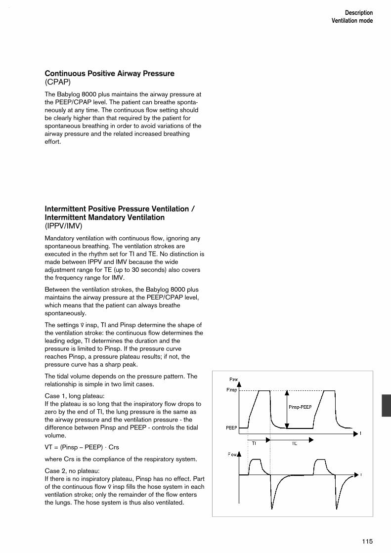
Continuous Positive Airway Pressure(CPAP)
The Babylog 8000 plus maintains the airway pressure atthe PEEP/CPAP level. The patient can breathe sponta-neously at any time. The continuous flow setting shouldbe clearly higher than that required by the patient forspontaneous breathing in order to avoid variations of theairway pressure and the related increased breathingeffort.
Intermittent Positive Pressure Ventilation / Intermittent Mandatory Ventilation(IPPV/IMV)
Mandatory ventilation with continuous flow, ignoring anyspontaneous breathing. The ventilation strokes areexecuted in the rhythm set for TI and TE. No distinction ismade between IPPV and IMV because the wideadjustment range for TE (up to 30 seconds) also coversthe frequency range for IMV.
Between the ventilation strokes, the Babylog 8000 plusmaintains the airway pressure at the PEEP/CPAP level,which means that the patient can always breathespontaneously.
The settings * insp, TI and Pinsp determine the shape ofthe ventilation stroke: the continuous flow determines theleading edge, TI determines the duration and thepressure is limited to Pinsp. If the pressure curvereaches Pinsp, a pressure plateau results; if not, thepressure curve has a sharp peak.
The tidal volume depends on the pressure pattern. Therelationship is simple in two limit cases.
Case 1, long plateau:If the plateau is so long that the inspiratory flow drops tozero by the end of TI, the lung pressure is the same asthe airway pressure and the ventilation pressure - thedifference between Pinsp and PEEP - controls the tidalvolume.
VT = (Pinsp – PEEP) · Crs
where Crs is the compliance of the respiratory system.
Case 2, no plateau:If there is no inspiratory plateau, Pinsp has no effect. Partof the continuous flow * insp fills the hose system in eachventilation stroke; only the remainder of the flow entersthe lungs. The hose system is thus also ventilated.
115
DescriptionVentilation mode

The tidal volume is approximately
VT = TI · * insp · Crs/(Crs + Cs)
where Cs is the compliance of the hose system. Theeffects of the hose system can be considerable, particu-larly with small patients, because Crs and Cs are appro-ximately equal.If, for example, Crs = Cs = 0.5 mL/mbar, only half of theset continuous flow actually enters the patient's lungs.
This effect (the fact that the hose system is also venti-lated) occurs on all ventilators. In order to measure theactual inspired and expired tidal volume, the flow sensorof the Babylog 8000 plus is located in the Y-piece.
Synchronized Intermittent Positive Pressure Ventilation(SIPPV)
The ventilation strokes are synchronised with sponta-neous breathing. A stroke begins when a spontaneousinspiration is detected and ends after the inspiration timeTI.
The shape of the ventilation stroke is set just as forIPPV/IMV. The Babylog 8000 plus detects the sponta-neous inspiration by flow measurement. A ventilationstroke is triggered if– inspiratory flow is detected after an expiration and– the volume continuously inspired during the sponta-
neous inspiration (the trigger volume Vtrig) reaches the set trigger sensitivity and
– the volume Vtrig is inspired by the end of TE.
Furthermore, a ventilation stroke may not be triggeredless than 0.2 seconds after the end of the precedingstroke, so that the patient has time to breathe out.
The patient controls the ventilation frequency, which maybe up to
fmax= 1/(TI+0.2 s+RT)
where RT is the trigger response time, i.e. the time fromthe start of a spontaneous inspiration to the start of thetriggered ventilation stroke.
116
DescriptionVentilation mode

If the patient stops breathing, ventilation in IPPV/IMVmode is started.
SIPPV is suitable for patients with sufficient spontaneousbreathing and regulation. The patient can be weanedfrom the ventilator by gradually reducing the inspirationpressure.
Synchronized Intermittent Mandatory Ventilation (SIMV)
SIMV combines synchronised ventilation with sponta-neous breathing. In contrast to SIPPV, support is notprovided for each spontaneous inspiration, but only for asufficient number to ensure that ventilation is executedwith the set frequency. Between the ventilation strokes,the patient can breathe spontaneously, but receives nosupport from the ventilator.
In each time interval with the length TI+TE, the first spon-taneous inspiration triggers a ventilation stroke with thelength TI. Any further spontaneous inspiration during thisperiod is ignored. The ventilation strokes thus have theirregular rhythm of spontaneous breathing, but theiraverage frequency is the same as the set frequencyvalue.
Triggering is carried out in the same way as for SIPPV.
The shape of the ventilation stroke is adjusted as forIPPV/IMV.
In SIMV mode, the ventilation frequency can be adjustedjust as in IPPV/IMV mode. Triggered mandatory ventila-tion strokes alternate with spontaneous-breathing phaseswithout support, during which the patient must do all thebreathing work.By extending TE, it is thus possible to transfer an increas-ing proportion of the total breathing work from theventilator to the patient.
If the patient stops breathing, ventilation in IPPV/IMVmode is started.
SIMV is suitable for patients with sufficient spontaneousbreathing. Weaning can be carried out by graduallyincreasing TE and lowering the inspiratory pressure.
117
DescriptionVentilation mode

Pressure Support Ventilation(PSV)
The PSV mode operates in a manner which is basicallysimilar to SIPPV. In addition to the breathing frequency,however, the patient also controls the duration of the ven-tilation stroke via the flow in this mode. The mandatoryinspiration is terminated when the flow drops to 15 % ofthe maximum inspiratory flow, or after the time TI,whichever occurs first.
In order for the inspiratory flow to drop during the ventila-tion stroke, the pressure pattern must have a plateau (seethe description of IPPV/IMV). If this is the case, the lungpressure rises as the lungs fill, approaching the airwaypressure, and the flow decreases.The rate at which the lung pressure approaches theairway pressure depends on the time constant Trs of therespiratory system. The shorter the Trs, the faster thelungs fill with air. The ventilation stroke in PSV mode thusends when the lungs are almost full, and the effectiveinspiration time is optimally matched to the requirementsof the patient.
Triggering is carried out in the same manner as in SIPPVmode.
Apart from the inspiration time, the shape of the ventila-tion stroke is set in the same manner as for IPPV/IMVmode. If the plateau is too short, the ventilation stroke isterminated after time TI, as in SIPPV mode.
If the patient stops breathing, ventilation in IPPV/IMVmode is started.
PSV is suitable for patients with sufficient spontaneousbreathing and regulation. The patient can be weanedfrom the ventilator by gradually reducing the supportpressure.
118
DescriptionVentilation mode
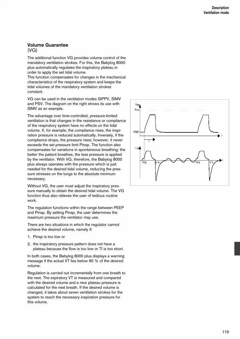
Volume Guarantee(VG)
The additional function VG provides volume control of themandatory ventilation strokes. For this, the Babylog 8000plus automatically regulates the inspiratory plateau inorder to apply the set tidal volume.This function compensates for changes in the mechanicalcharacteristics of the respiratory system and keeps thetidal volumes of the mandatory ventilation strokesconstant.
VG can be used in the ventilation modes SIPPV, SIMVand PSV. The diagram on the right shows its use withSIMV as an example.
The advantage over time-controlled, pressure-limitedventilation is that changes in the resistance or complianceof the respiratory system have no effects on the tidalvolume. If, for example, the compliance rises, the inspi-ration pressure is reduced automatically. Inversely, if thecompliance drops, the pressure rises; however, it neverexceeds the set pressure limit Pinsp. The function alsocompensates for variations in spontaneous breathing: thebetter the patient breathes, the less pressure is appliedby the ventilator. With VG, therefore, the Babylog 8000plus always operates with the pressure which is justneeded for the desired tidal volume, reducing the pres-sure stresses on the lungs to the absolute minimumnecessary.
Without VG, the user must adjust the inspiratory pres-sure manually to obtain the desired tidal volume. The VGfunction thus also relieves the user of tedious routinework.
The regulation functions within the range between PEEPand Pinsp. By setting Pinsp, the user determines themaximum pressure the ventilator may use.
There are two situations in which the regulator cannotachieve the desired volume, namely if:
1. Pinsp is too low or
2. the inspiratory pressure pattern does not have a plateau because the flow is too low or TI is too short.
In both cases, the Babylog 8000 plus displays a warningmessage if the actual VT lies below 90 % of the desiredvolume.
Regulation is carried out incrementally from one breath tothe next. The expiratory VT is measured and comparedwith the desired volume and a new plateau pressure iscalculated for the next breath. If the desired volume ischanged, it takes about seven ventilation strokes for thesystem to reach the necessary inspiration pressure forthis volume.
119
DescriptionVentilation mode

In the case of a serious leak in the tube, the expired VTmay (just as in other ventilation modes) be greater thanthat measured at the expiration connector. The inspiratorytidal volume will then differ from the expiratory tidalvolume. If, in the course of a ventilation stroke, the actualinspiratory VT exceeds the VTe of the previous stroke byan amount which depends on the actual leakage, theBabylog 8000 plus terminates the inspiration stroke.
If the flow sensor fails, or if the patient stops breathingspontaneously, mandatory ventilation is started as inIPPV/IMV mode.
High-Frequency Ventilation
(HFV)
Ventilation with high-frequency pressure oscillationspermits gas exchange in the lungs in spite of the verysmall tidal volumes - often in the same order of magnitudeas the dead space volume. While the pressure variationsin the hose system can be fairly large, the lungs aresubjected only to small variations around the meanpressure. The mechanical stresses resulting fromdistension and relief of the lungs are small.
Principle of operation
The high-frequency pulses, just like the breathing cyclesin conventional mandatory ventilation, are controlled withthe aid of the diaphragm of the expiration valve. Duringthe inspiration phases of the HF oscillations, the pressureis above the mean airway pressure; during the expirationphases, it is below this value. The mean pressure isautomatically regulated to the value set with thePEEP/CPAP rotary knob.
For this regulation, the ventilator must automatically setthe continuous flow and the I:E ratio of the HF cycles.With HFV active, the rotary knob for the continuous flowis disabled. Furthermore, the VIVE option cannot be usedtogether with HFV.
The pressure amplitudes at the Y-piece depend on theamplitude setting and also on the hose system and therespiratory system of the patient. It is thus necessary toadjust the amplitude on the relative scale from 0 to 100 % until the desired pressure or the desired tidalvolume is achieved.
120
DescriptionVentilation mode

HFV with CPAP
The high-frequency oscillations are continuously super-imposed on the mean pressure (PEEP/CPAP).
HFV with IMV
The high-frequency oscillations are superimposed on thePEEP/CPAP pressure during the expiration time TEbetween the IMV strokes. They stop 100 millisecondsbefore an IMV stroke and start again 250 millisecondsafter the stroke. The delay after the stroke is intended toensure sufficient time for expiration and to avoid air-trapping.
The IMV strokes are controlled by the settings * insp,Pinsp, PEEP/CPAP and TI.
Due to the IMV strokes, the mean airway pressure isslightly higher than for HFV with CPAP.
During the HF phases, the pressure again oscillatesaround the PEEP/CPAP level.
Monitoring with HFV
As for conventional ventilation, the ventilation curves forpressure and flow are measured and optionally displayed.As a special feature for HFV, the following are measured:
DCO2 = VTHF^2 · f
This is the transport coefficient for CO2, which is anindication of the amount of volume ventilation during HFV,rather like the minute volume for conventional ventilation.
VTHF
This is the tidal volume of the HF pulses, averaged overseveral HF cycles.
MVim
This is the minute volume taken up by IMV strokes,measured on the inspiration side.
VTim
This is the minute volume taken up by IMV strokes,measured on the expiration side.
121
DescriptionMonitoring functions

Measurement of airway pressure
The Babylog 8000 plus measures the airway pressureindirectly in order to avoid the need for a separatepressure-measurement hose to the Y-piece. Two piezo-resistive pressure sensors measure the pressures at theinspiration connector (PI) and at the expiration connector(PE) within the ventilator. The airway pressure PY iscalculated from these two values.
Due to the fact that the ventilator operates with a con-tinuous flow, the inspiratory pressure PI is the startingpoint for this. The continuous flow V insp generates apressure drop in the inspiratory leg of the Y-piece whichdepends on the resistance RI of the inspiration hose andthe value of * insp, as follows:
P = * insp · RI
P depends only slightly on the ventilation pattern. Thedesired pressure at the Y-piece is thus approximatelyequal to the pressure PI reduced by the pressure P:
PY = PI - P = PI - * insp · RI
The airway pressure at the Y-piece can thus be calcula-ted if the resistance RI is known.
The total resistance of the hose system can be measuredduring ventilation with the aid of the sensors for PI andPE. It is not, however, possible to determine the inspi-ratory component of this total value.Comprehensive laboratory tests have shown that theinspiratory leg of all commonly used hose systemsaccounts for about 70 % of the total resistance. TheBabylog 8000 plus therefore uses this estimate forcalculations:
PY = PI – 0.7 · < PI – PE >
where <PI – PE> represents the average over time of thepressure drop in the entire hose system. If a hose systemwith a resistance distribution other than 30 % to 70 % isused, there will be an error in the measured airwaypressure. With the hose systems in general use, thiserror is less than 1 mbar, but it may be greater in veryresistive systems, particularly if high continuous flowrates are used. For this reason, only hoses with aninternal diameter of at least 10 mm should be used.
122
DescriptionMonitoring functions

Measurement of flow and volume
The flow is measured with a hot-wire anemometer in theY-piece or with a sensor fitted between the Y-piece andthe tube. The direction of flow is detected by using twohot wires, one of which is shielded by a baffle on oneside.
The lowest flow rate which can be detected reliably is 0.2 L/min. Flow rates below this are suppressed anddisplayed as zero.
There are two different types of flow sensors available:
the Y-sensor, integrated into the Y-piece and
the ISO sensor, inserted between the Y-piece and thetube connector.
Both types use the same sensor insert, but theircharacteristics are nevertheless not identical. The type offlow sensor being used is selected in the menu in orderto optimise the measurement function.
Reference condition
Primarily, hot-wire anemometers measure quantities ofgas, rather than volumes or flow rates. As defined in thestate equation for gases, the volume of a specific amountof gas depends on the ambient conditions, namelyatmospheric pressure, temperature and relative humidity.
The Babylog 8000 plus displays the measured volumeand flow values for one of two different referenceconditions:
NTPD (temperature 20 °C, atmospheric pressure1013 mbar, dry air) or
BTPS (body temperature 37 °C, actual atmosphericpressure, air saturated with moisture).
The desired reference condition is selected in the menu.
Leakage rate
If the tube is not a tight fit, some air will often escapebetween the wall of the trachea and the tube. Since theflow sensor of the Babylog 8000 plus is located in the Y-piece, i.e. upstream of the leak, breathing gas is lost aftermeasurement during inspiration and before measurementduring expiration. The tidal volume measured on the inspi-ration side is thus larger than the actual tidal volume,while that measured on the expiration side is smaller.Averaged over time, the difference between the inspira-tory and expiratory flow is equal to the leakage flow,since the amount of gas which does not flow backthrough the sensor during expiration must have escapedthrough the leak.
123
DescriptionMonitoring functions

The Babylog 8000 plus determines the leakage flow fromthe difference between the inspiratory minute volume MViand the expiratory minute volume MVe (which isdisplayed as MV). Normalised for MVi, the leakage rate inpercent displayed on the screen is:
Leakage rate = 100 % · (MVi - MVe) / MVi
Trigger function
The Babylog 8000 plus detects spontaneous breathingby measuring the flow. When the patient attempts tobreath in, the flow signal, which was until then zero ornegative (= expiration), starts to rise. In order to reliablydetect inspiration, and to avoid triggering a ventilationstroke as the result of interference signals, the patientmust first breathe in a certain volume Vtrig. This volume isset as the trigger sensitivity on a scale from 1 to 10 in themenu, where 1 is the highest and 10 is the lowest sensi-tivity. The diagram on the right shows the relationshipbetween the sensitivity and the trigger volume Vtrig.
At the maximum sensitivity, Vtrig = 0 and the inspiratoryflow needs to reach only the minimum value of 0.2 L/minin order to trigger a stroke. However, it is possible forstrokes to be triggered by artefacts at this setting. If self-triggering occurs, the sensitivity should be reduced.
With decreasing sensitivity, the delay between the spont-aneous inspiration and the ventilation stroke increases.This delay may not be so long that the inspiration strokehinders the spontaneous expiration, since the patientwould then have to "fight" the ventilator. The best sensi-tivity is thus always a compromise between the shortestpossible trigger delay and the reliable protection againstself-triggering.
124
DescriptionMonitoring functions

Measuring lung parameters
The Babylog 8000 plus calculates the followingparameters from the pressure, flow and volumeventilation curves for a ventilation cycle:
CThe dynamic compliance of the respiratory system,calculated by linear regression.
RThe resistance of the airways and the ET tube,calculated by linear regression.
rThe correlation coefficient.
TCThe time constant of the respiratory system (TC = R · C).
C20/CThe overdistension index, calculated in accordancewith [1]
The Babylog 8000 plus 5.n first stores all measuredvalues Paw(t), flow(t) and V(t) for one ventilation strokewith a maximum duration of 5 seconds. 120 measuredvalues are taken per second. These data are thenevaluated and the results are displayed. A furtherventilation cycle is then stored and evaluated, and so on.The displayed results do not, therefore, belong to thecurrent ventilation cycle; in general, they are severalseconds old.
The calculation is based on the equation
Paw = R · Flow + V/C
which is valid for a single-compartment model of the res-piratory system at any point in time during a ventilationstroke. The resistance and compliance are assumed tobe constant. The linear regression method finds thevalues for R and C which best match the measuredvalues pressure, flow and volume. The correlation coef-ficient, which is a number between 0 and 1, is an indi-cation for the quality of the match. The closer this coef-ficient is to 1, the better the agreement.
Since the Babylog 8000 plus knows only the airwaypressure, but not the pleura or oesophageal pressure,spontaneous breathing cannot be taken into account. Ifstrong spontaneous breathing is superimposed on theventilation, the results of the evaluation will be falsified.
The same applies if there is a major leak: the displayedvalue for resistance and compliance will be too high.
125
DescriptionMonitoring functions

Possible falsification of the results by the above-mentioned conditions is indicated by a warning symbolon the screen. This is displayed if r is less than 0.95, ifthe leakage in the displayed curve is greater than 20% orif there is strong spontaneous breathing.
For the overdistension index, the ratio C20 is calculatedfrom the volume increase from the last 20% of theinspiration pressure and is referred to the dynamiccompliance [1]:
C20 = (V(TI) – V(t80)) / (0.2 · Ppeak)
The results remain displayed until the next evaluationcycle has been completed. If, however, no newmeasured values are available within one minute, thedisplay is cleared.
[1]Identifying lung overdistention during mechanical ventilation by usingvolume-pressure loops by Joel B. Fisher, Mark C. Mammel, Michael C.Coleman, Dennis R. Bing, Stephen J. Boros Pediatric Pulmonology5:10-14 (1988)
DescriptionMonitoring functions
126
Rate-Volume Ratio (RVR)
The ratio of the breathing rate to the tidal volume can helpto assess the chances of successfully weaning thepatient from the ventilator [1]. The Babylog 8000 pluscalculates and displays the RVR. In order to avoidfluctuations of the measured value due to switchingbetween spontaneous and mandatory breathing cycles,the ratio between the rate and the volume is not formeddirectly. Instead, the RVR is calculated with the formula
RVR = f / VT = f2 / MV
which is equivalent to averaging the RVR over a period of10 to 15 seconds.
[1]A prospective study of indexes predicting the outcome of trials ofweaning from mechanical ventilation;by Karl L. Yang, Martin J. TobinThe New England Journal of Medicine, Vol 324, 21, 1991
127
DescriptionMonitoring functions
Explanation of abbreviations
Abbreviation MeaningC Compliance
CPAP Continuous Positive Airway Pressure Breathing
DCO2 Transport coefficient which describes the transport of CO2 out of the lungs
f Frequency
FiO2 Inspiratory O2 concentration
Fpat Spontaneous breathing frequency
HFV High Frequency-Ventilation
IMV Intermittent Mandatory Ventilation
IPPV Intermittent Positive Pressure Ventilation
IRV Inversed Ratio Ventilation
ISO 5369 International standard for medical ventilation equipment – lung ventilators
KG Body weight [kg]
MV Minute volume
MVim Minute volume applied by mandatory ventilation strokes during high-frequency ventilation, measured on the inspiration side
Paw Airway pressure
Peak peak pressure
PEEP Positive end-expiratory pressure
Mean Mean pressure
Pinsp. Maximum inspiration pressure
R Resistance
RT Trigger Response Time
RVR Rate-Volume Ratio
SIPPV Synchronized Intermittent PositivePressure Ventilation
TI:TE Ratio inspiration time : expiration time
TI Inspiration time
TE Expiration time
* Inspiratory and expiratory flow
* insp. Inspiratory flow
*exsp. Expiratory flow
VIVE Variable Inspiratory flow, VariableExpiratory flow
VT Tidal volume
VTHF Tidal volume generated by high-frequency pulses, averaged over several high-frequency pulses
VTim Tidal volume applied by mandatory ventilation strokes during high-frequency ventilation, measured on the inspiration side
Vtrig Trigger volume
DescriptionExplanation of abbreviations
128

Explanation of symbols on the screen and keys
Menu for setting the minute-volume alarm limits
Upper alarm limit
Lower alarm limit
Menu for the log
Reduce or scroll backwards
Increase or scroll forwards
Reduce time window
Increase time window
Move time window or select parameter
Move time window or select parameter
G Disable alarm tone for 2 minutes
l Horn/alarm tone
Pulse signal for display of events during ventilation
Return to main menu
Increase
Decrease
Select parameter
Call the calibration/configuration menu
Call the ventilation menu
Call the ventilation options menu(optional functions)
[Flow Flow measurement is switched off
[FiO2 FiO2 measurement is switched off
[Apn Apnoea monitoring is switched off
129
DescriptionExplanation of symbols
Cal.Config
Vent.Mode
Vent.Option
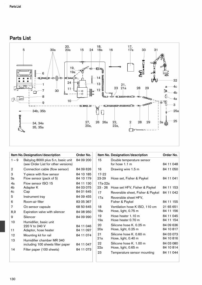
Parts List
130
Parts List
Item No.Designation/description Order No.
1 – 9 Babylog 8000 plus 5.n, basic unit 84 09 200(see Order List for other versions)
2 Connection cable (flow sensor) 84 09 626
3 Y-piece with flow sensor 84 10 1853a Flow sensor (pack of 5) 84 10 179
4a Flow sensor ISO 15 84 11 1304b Adapter K 84 03 0754c Cap 84 01 645
5 Instrument tray 84 09 455
6 Room-air filter 83 05 367
7 O2 sensor capsule 68 50 645
8,9 Expiration valve with silencer 84 08 950
9 Silencer 84 09 990
10 Humidifier, basic unit220 V to 240 V 84 11 046
11 Adaptor, hose heater 84 11 097
12 Mounting kit for rail 84 11 074
13 Humidifier chamber MR 340including 100 sheets filter paper 84 11 047
14 Filter paper (100 sheets) 84 11 073
Item No. Designation/description Order No.
15 Double temperature sensorfor hose 1.1 m 84 11 048
16 Drawing wire 1.5 m 84 11 050
17-2223-29 Hose set, Fisher & Paykel 84 11 041
17a-22a23 - 26 Hose set HFV, Fisher & Paykel 84 11 153
17 Reversible sheet, Fisher & Paykel 84 11 042
17a Reversible sheet HFV, Fisher & Paykel 84 11 155
18 Ventilation hose K ISO, 110 cm 21 65 65118a Hose, light, 0.75 m 84 11 156
19 Hose heater 1.10 m 84 11 04519a Hose heater 0.70 m 84 11 154
20 Silicone hose K. 0.25 m 84 09 63620a Hose, light, 0.25 m 84 10 817
21 Silicone hose K. 0.60 m 84 03 07321a Hose, light, 0.40 m 84 10 816
22 Silicone hose K. 1.00 m 84 03 08022a Hose, light, 0.65 m 84 10 814
23 Temperature sensor mounting 84 11 044
1
7
8
9
5 30a 20a 15 24 18a 16 17a 33 3120, 18, 17,
32
4c
4b
4a
3
25a
25
6
30
19,19a
24
11
10
14
13
12 23 21a 28 2921,
27, 26 26a 22, 2 28 29 3a
34b, 35b
34, 34a35, 35a 20a, 22a,
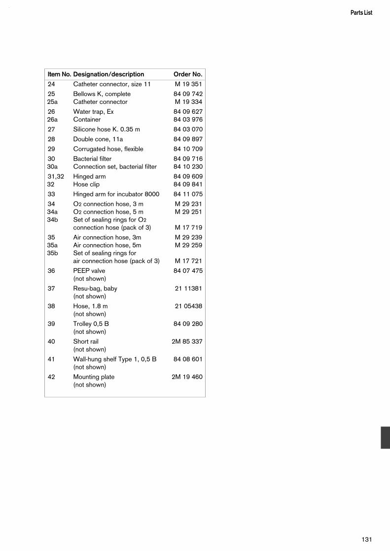
Item No. Designation/description Order No.
24 Catheter connector, size 11 M 19 351
25 Bellows K, complete 84 09 74225a Catheter connector M 19 334
26 Water trap, Ex 84 09 62726a Container 84 03 976
27 Silicone hose K. 0.35 m 84 03 070
28 Double cone, 11a 84 09 897
29 Corrugated hose, flexible 84 10 709
30 Bacterial filter 84 09 71630a Connection set, bacterial filter 84 10 230
31,32 Hinged arm 84 09 60932 Hose clip 84 09 841
33 Hinged arm for incubator 8000 84 11 075
34 O2 connection hose, 3 m M 29 23134a O2 connection hose, 5 m M 29 25134b Set of sealing rings for O2
connection hose (pack of 3) M 17 719
35 Air connection hose, 3m M 29 23935a Air connection hose, 5m M 29 25935b Set of sealing rings for
air connection hose (pack of 3) M 17 721
36 PEEP valve 84 07 475(not shown)
37 Resu-bag, baby 21 11381(not shown)
38 Hose, 1.8 m 21 05438(not shown)
39 Trolley 0,5 B 84 09 280(not shown)
40 Short rail 2M 85 337(not shown)
41 Wall-hung shelf Type 1, 0,5 B 84 08 601(not shown)
42 Mounting plate 2M 19 460(not shown)
131
Parts List

Order List
132
Order List
Designation/description Order No.
Babylog 8000 plus 5.n, basic unitOptional voltages:100 V – 127 V / 220 V – 240 V 84 11 163
Babylog 8000 plus 5.n, basic unitOptional voltages:100 V – 127 V / 220 V – 240 Vwith BabyLink option 84 11 162
Babylog 8000 plus 5.n, basic unitOptional voltages:100 V – 127 V / 220 V – 240 Vwith HFV option 84 11 161
Babylog 8000 plus 5.n, basic unitOptional voltages:100 V – 127 V / 220 V – 240 Vwith BabyLink and HFV options 84 11 160
O2 sensor capsule 68 50 645
Babylog 8000 plus 5.nwith options "Pressure Support Ventilation PSV" and "Volume Guarantee VG" 84 18 003
Babylog 8000 plus 5.nwith options "High-Frequency Ventilation HFV","Pressure Support Ventilation PSV" and "Volume Guarantee VG" 84 18 001
Babylog 8000 plus 5.nwith options "BabyLink", "Pressure Support Ventilation PSV" and "Volume Guarantee VG" 84 18 002
Babylog 8000 plus 5.nwith options "High-Frequency Ventilation HFV","Pressure Support Ventilation PSV", "Volume Guarantee VG" and "BabyLink" 84 18 000
Accessories designed for use with the basic unit
Hose set, Fisher & Paykel 84 11 041
Hose set HFV, Fisher & Paykel 84 11 153
optionally
Trolley 0,5 B 84 09 280for mounting the Babylog 2M 85 337
Wall-hung shelf 0,5 Bfor mounting the Babylog 84 10 718
Mounting plate for use on an incubator 2M 19 460
Designation/description Order No.
Hinged arm for use outside an incubator,with mounting for hinged arm 84 09 609
Hose clips for incubator 8000 84 11 075
Basic humidifier unit MR 340, 220 V – 240 V 84 11 046
Humidifier chamber MR 340, including100 sheets of filter paper 84 11 047
Gas connection hoses
O2 connection hose, 3 m M 29 231orO2 connection hose, 5 m M 29 251
Air connection hose, 3 m M 29 239orAir connection hose, 5 m M 29 259
Special accessories
Conversion kit "High-Frequency Ventilation HFV"(for units up to Serial No. ARHC) 84 11 134(for units with Serial No. ARHD onwards) 84 11 208
Conversion kit "BabyLink" 84 11 108
Resu-bag »Baby«for manual ventilation 21 11 381
plusPEEP valve 84 07 475
Hose, 1.8 m, for O2 supply toResu-bag »Baby« 21 05 438
Water traps IN / EX 84 09 738
High-pressure water trap 84 12 628
Safety valve 84 12 448
Conversion kit "Pressure Support Ventilation PSV" and "Volume Guarantee VG" 84 11 473
Conversion kit "Medicament nebulizer" 84 11 025
consisting of:Coupling 84 11 023Connector 84 05 752Catheter connector 11mm M 19 351Sealing plug for Y-piece 84 11 024Medicament nebulizer 84 05 000

Designation/description Order No.
Replacement sets for sterilisation
Hose set, Fisher & Paykel 84 11 041
Hose set HFV, Fisher & Paykel 84 11 153
Expiration valve, Babylog 8000 plus 84 08 950
Y-piece with flow sensor 84 10 185
Flow sensor ISO 15 84 11 130
Adapter K 84 03 075
Cap 84 01 645
Spare and replacement parts
Hose set, Fisher & Paykel 84 11 041Hose set HFV, Fisher & Paykel 84 11 153
Expiration valve, Babylog 8000 plus 84 08 950
Y-piece with flow sensor 84 10 185
Flow sensors (pack of 5) 84 10 179Flow sensor ISO 15 84 11 130
Adapter K 84 03 075
Cap 84 01 645
O2 sensor capsule 68 05 645
Cable for double temperature sensorfor hose, 1.1 m 84 11 048
Drawing wire, 1.5 m 84 11 050
Hose heater, 1.1 m 84 11 045
Hose heater, 0.7 m 84 11 154
Room-air filter 83 05 367
Set of sealing rings for medical-airconnection hose (pack of 3) M 17 721
Set of sealing rings for O2
connection hose (pack of 3) M 17 719
Flow-sensor cable 84 09 626
Silicone hose K 0.12 m 84 09 680Silicone hose K 0.25 m 84 09 636Silicone hose K 0.40 m 84 03 070Silicone hose K 0.60 m 84 03 073Silicone hose K 1.00 m 84 03 080Silicone hose K 1.20 m 84 10 189
Hose (light) 0.12 m 84 10 819Hose (light) 0.25 m 84 10 817Hose (light) 0.40 m 84 10 816Hose (light) 0.65 m 84 10 814Hose (light) 1.00 m 84 10 815Hose (light) 1.20 m 84 10 818
133
Order List
Designation/description Order No.
Double cone 11a 84 09 897
Technical documents available on request

Index
Abbreviations...........................................................128Alarm limits.................................................................49Alarm tone level.......................................................... 63Alarms........................................................................61Apnoea time............................................................... 49
Battery.......................................................................93Breathing-gas humidifier............................................. 18
Calibration..................................................................24Caution...................................................................... 61Compliance................................................................57Connections.............................................................108Contrast..................................................................... 64Cooling-air filter.......................................................... 93CPAP.....................................................................8, 33
Disinfecting/cleaning/sterilising.................................. 84Displaying airway pressure curve Paw........................ 55Displaying flow curve *.............................................. 55Displaying lung values................................................ 57Displaying measured pressure values......................... 56Displaying measured values........................................55Displaying measured volume values............................ 57
Electrical supply.........................................................18Equipment check........................................................28Expiration valve
fitting.....................................................................17cleaning/disinfecting..............................................84
Expiratory flow............................................................48
Fault - Cause - Remedy..............................................77Flow measurement..................................................... 25Flow sensor
calibrating..............................................................25cleaning/disinfecting..............................................85replacing............................................................... 27
Flow-sensor cable...................................................... 21Freezing curve display................................................ 56
Gas supply.................................................................18Gas-failure alarm........................................................ 88
High-frequency ventilation.......................................... 46Hinged arm................................................................ 19Humidifier...................................................................18
IMV..................................................................8, 36, 46Incubator..............................................................20, 53Inspiration, starting manually....................................... 51
Instrument tray............................................................16IPPV.......................................................................8, 36
Language...................................................................64Log............................................................................ 62Lung parameters................................................ 57, 105
Main menu................................................................. 12Main switch..........................................................22, 99Mains-failure alarm......................................................87Maintenance intervals................................................. 92Manual ventilation facility.............................................. 8Measured-value field...................................................11Menu layout................................................................12Menu line................................................................... 11Minute volume............................................................ 49Monitoring menu.........................................................13Monitoring ventilation....................................................8
Nebulizing medicaments.............................................52
O2 sensor.................................................................. 24O2 sensor capsule......................................................17Operating concept....................................................... 9Oxygen measurement.................................................24
Panting...................................................................... 49Parts list...................................................................130Plateau....................................................................... 36Pneumatic circuit......................................................112PSV........................................................................... 41
Resistance................................................................. 57RVR......................................................................... 127
Screenselecting functions.................................................11
Screen layout............................................................. 11Settings......................................................................59Silencer................................................................17, 98SIMV..................................................................40, 117SIPPV................................................................ 39, 116Status field................................................................. 11Synchronising.............................................................41
Technical data..........................................................102Time constant.............................................................57Time/date................................................................... 63Trigger delay............................................................ 103Trigger sensitivity................................................35, 124Trigger volume....................................................35, 116Trolley........................................................................ 16
Index
134

Ventilation hosesfitting.....................................................................19removing............................................................... 84
VG............................................................................. 44VIVE.......................................................................8, 48
Water hoses...............................................................20Water trap..................................................................19
Y-piece, fitting............................................................21Y-sensor.....................................................................21
135
Index

These Instructions for Use apply only toBabylog 8000 plus 5.nwith Serial No.:
If no Serial No. has been filled in byDräger these Instructions for Use areprovided for general information only andare not intended for use with any specificmachine or device.
90 28 884 - GA 6173.320 en Dräger Medizintechnik GmbH2nd edition - March 1999Subject to alteration
çDirective 93/42/EECconcerning Medical Devices
Dräger Medizintechnik GmbHGermanyH Moislinger Allee 53 – 55
D-23542 LübeckT (4 51) 8 82 - 0X 26 80 70FAX (4 51) 8 82-20 80! http://www.draeger.com