Instructions for Use - Draeger Web App · 4 Dräger Polytron 5000 For your safety 1 For your safety...
16
WARNING Strictly follow the Instructions for Use. The user must fully understand and strictly observe the instructions. Use the product only for the purposes specified in the Intended use section of this document. ! i Dräger Polytron 5000 Instructions for Use
Transcript of Instructions for Use - Draeger Web App · 4 Dräger Polytron 5000 For your safety 1 For your safety...

WARNINGStrictly follow the Instructions for Use. The user must fully understand and strictly observe the instructions. Use the product only for the purposes specified in the Intended use section of this document.
!
i
Dräger Polytron 5000
Instructions for Use


Content
Content
1 For your safety . . . . . . . . . . . . . . . . . . . . . . . . . . . . .41.1 General safety statements . . . . . . . . . . . . . . . . . . . .41.2 Definition of alert icons . . . . . . . . . . . . . . . . . . . . . . .4
2 Description . . . . . . . . . . . . . . . . . . . . . . . . . . . . . . . .52.1 Product overview . . . . . . . . . . . . . . . . . . . . . . . . . . .52.2 Intended use . . . . . . . . . . . . . . . . . . . . . . . . . . . . . . .52.3 Intended operating area and operating conditions . .5
3 Operation . . . . . . . . . . . . . . . . . . . . . . . . . . . . . . . . .63.1 Principle of operation . . . . . . . . . . . . . . . . . . . . . . . .63.2 Installation . . . . . . . . . . . . . . . . . . . . . . . . . . . . . . . . .63.3 Installing the sensor . . . . . . . . . . . . . . . . . . . . . . . . .73.4 Replacing the sensor . . . . . . . . . . . . . . . . . . . . . . . .83.5 Menu . . . . . . . . . . . . . . . . . . . . . . . . . . . . . . . . . . . . .83.5.1 Menu navigation . . . . . . . . . . . . . . . . . . . . . . . . . . . .83.5.2 Changing parameter values/status . . . . . . . . . . . . . .83.5.3 Exiting the Menu . . . . . . . . . . . . . . . . . . . . . . . . . . . .83.6 Menu items . . . . . . . . . . . . . . . . . . . . . . . . . . . . . . . .83.6.1 Sensor lock . . . . . . . . . . . . . . . . . . . . . . . . . . . . . . . .83.6.2 Gas conc . . . . . . . . . . . . . . . . . . . . . . . . . . . . . . . . . .93.6.3 Password . . . . . . . . . . . . . . . . . . . . . . . . . . . . . . . . .93.6.4 Password adj . . . . . . . . . . . . . . . . . . . . . . . . . . . . . .93.6.5 Zero adj . . . . . . . . . . . . . . . . . . . . . . . . . . . . . . . . . . .93.6.6 Span adj . . . . . . . . . . . . . . . . . . . . . . . . . . . . . . . . . .93.6.7 FSD adj . . . . . . . . . . . . . . . . . . . . . . . . . . . . . . . . . . .93.6.8 A1 adj . . . . . . . . . . . . . . . . . . . . . . . . . . . . . . . . . . . .93.6.9 A2 adj . . . . . . . . . . . . . . . . . . . . . . . . . . . . . . . . . . . .93.6.10 A1 lat . . . . . . . . . . . . . . . . . . . . . . . . . . . . . . . . . . . . .93.6.11 A2 lat . . . . . . . . . . . . . . . . . . . . . . . . . . . . . . . . . . . . .93.6.12 A1 acn . . . . . . . . . . . . . . . . . . . . . . . . . . . . . . . . . . . .93.6.13 A2 acn . . . . . . . . . . . . . . . . . . . . . . . . . . . . . . . . . . . .93.6.14 Cal sig . . . . . . . . . . . . . . . . . . . . . . . . . . . . . . . . . . . .93.7 Output and display variations . . . . . . . . . . . . . . . . . .9
4 Maintenance . . . . . . . . . . . . . . . . . . . . . . . . . . . . . .104.1 Calibration procedure for toxic gases . . . . . . . . . . .104.1.1 Zero calibration . . . . . . . . . . . . . . . . . . . . . . . . . . . .104.1.2 Span calibration . . . . . . . . . . . . . . . . . . . . . . . . . . .104.2 Calibration procedure for oxygen . . . . . . . . . . . . . .114.2.1 Zero calibration . . . . . . . . . . . . . . . . . . . . . . . . . . . .114.2.2 Span calibration . . . . . . . . . . . . . . . . . . . . . . . . . . .114.3 Error messages . . . . . . . . . . . . . . . . . . . . . . . . . . . .11
5 Disposal of electrical and electronic equipment 11
6 Technical data . . . . . . . . . . . . . . . . . . . . . . . . . . . .126.1 Approvals . . . . . . . . . . . . . . . . . . . . . . . . . . . . . . . .126.2 Signal transmission to central control unit . . . . . . .126.3 Voltage of power supply . . . . . . . . . . . . . . . . . . . . .126.4 Physical specifications . . . . . . . . . . . . . . . . . . . . . .126.5 Environmental parameters . . . . . . . . . . . . . . . . . . .126.6 Ambient influences . . . . . . . . . . . . . . . . . . . . . . . . .12
7 Default values. . . . . . . . . . . . . . . . . . . . . . . . . . . . .12
8 Order list . . . . . . . . . . . . . . . . . . . . . . . . . . . . . . . . 138.1 Sensors . . . . . . . . . . . . . . . . . . . . . . . . . . . . . . . . . 138.2 Accessories . . . . . . . . . . . . . . . . . . . . . . . . . . . . . . 138.3 Spare parts . . . . . . . . . . . . . . . . . . . . . . . . . . . . . . 13
Dräger Polytron 5000 3

For your safety
1 For your safety
1.1 General safety statementsBefore using this instrument, carefully read the Instructions for Use (IfU).Strictly follow the Instructions for Use. The user must fully understand and strictly observe the instructions. Use the instrument only for purposes and under the conditions specified in this document.Comply with all local and national laws, rules and regulations associated with this instrument.Only trained and competent personnel are permitted to inspect, repair and service the product as detailed in these Instructions for Use. Further maintenance work that is not detailed in these Instructions for Use must only be carried out by Dräger or personnel qualified by Dräger. Dräger recommends a Dräger service contract for all maintenance activities.Use only genuine Dräger spare parts and accessories, otherwise the proper functioning of the instrument may be impaired.The flameproof/explosion proof joints are not in accordance with the relevant minimum or maximum values of EN/IEC 6009-1. The joints are not intended to be re-worked by the user.Do not dispose of the Instructions for Use. Ensure that they are retained and appropriately used by the instrument user.The measuring function of the gas detection transmitter for explosion protection, according to Annex II, clauses 1.5.5, 1.5.6 and 1.5.7 of Directive 94/9/EC is currently not covered.Substitution of components may impair Intrinsic Safety. Only if intrinsic safety is involved
Safe connection of electrical devices.Never connect this instrument to another electrical device before consulting the manufacturer or an expert.
Using the product in areas subject to explosion hazards:Instruments or components for use in explosion-hazard areas which have been tested and approved according to national, European or international Explosion Protection Regulations may only be used under the conditions specified in the approval and with consideration of the relevant legal regulations.The instruments or components may not be modified in any manner. The use of faulty or incomplete parts is forbidden. The appropriate regulations must be observed at all times when carrying out repairs on these instruments or components.
1.2 Definition of alert iconsTo reduce the risk of ignition of a flammable or explosive atmosphere, strictly adhere to the following Caution and Warning statements.The following alert icons are used in this document to provide and highlight areas of the associated text that require a greater awareness by the user. A definition of the meaning of each icon is as follows:
DANGERIndicates an imminently hazardous situation which, if not avoided, will result in death or serious injury.
WARNINGIndicates a potentially hazardous situation which, if not avoided, could result in death or serious injury.
CAUTIONIndicates a potentially hazardous situation which, if not avoided, could result in physical injury, or damage to the product or environment.It may also be used to alert against unsafe practices.
NOTICEIndicates additional information on how to use the instrument.
!
!
!
ii
4 Dräger Polytron 5000
Description
2 Description
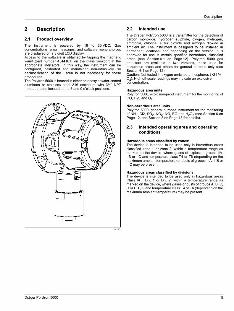
2.1 Product overviewThe instrument is powered by 16 to 30 VDC. Gas concentrations, error messages, and software menu choices are displayed on a 3 digit LCD display. Access to the software is obtained by tapping the magnetic wand (part number 4544101) on the glass viewport at the appropriate indicators. In this way, the instrument can be configured, calibrated and maintained non-intrusively, so declassification of the area is not necessary for these procedures.The Polytron 5000 is housed in either an epoxy powder-coated aluminum or stainless steel 316 enclosure with 3/4” NPT threaded ports located at the 3 and 9 o’clock positions.
2.2 Intended useThe Dräger Polytron 5000 is a transmitter for the detection of carbon monoxide, hydrogen sulphide, oxygen, hydrogen, ammonia, chlorine, sulfur dioxide and nitrogen dioxide in ambient air. The instrument is designed to be installed in permanent locations, and depending on the version, it is approved for use in certain specified hazardous, classified areas (see Section 6.1 on Page 12). Polytron 5000 gas detectors are available in two versions, those used for hazardous areas and others for general purpose only (see Section 6.1 on Page 12).Caution: Not tested in oxygen enriched atmospheres (>21 % O2). High off-scale readings may indicate an explosive concentration.
Hazardous area unitsPolytron 5000, explosion-proof instrument for the monitoring of CO, H2S and O2.
Non-hazardous area unitsPolytron 5000, general purpose instrument for the monitoring of NH3, Cl2, SO2, NO2, NO, EO and H2O2 (see Section 6 on Page 12, and Section 8 on Page 13 for details).
2.3 Intended operating area and operating conditions
Hazardous areas classified by zones:The device is intended to be used only in hazardous areas classified zone 1 or zone 2, within a temperature range as marked on the device, where gases of explosion groups IIA, IIB or IIC and temperature class T4 or T6 (depending on the maximum ambient temperature) or dusts of groups IIIA, IIIB or IIIC may be present.
Hazardous areas classified by divisions:The device is intended to be used only in hazardous areas Class I&II, Div. 1 or Div. 2, within a temperature range as marked on the device, where gases or dusts of groups A, B, C, D or E, F, G and temperature class T4 or T6 (depending on the maximum ambient temperature) may be present.
Dräger Polytron 5000 5
Operation
3 Operation
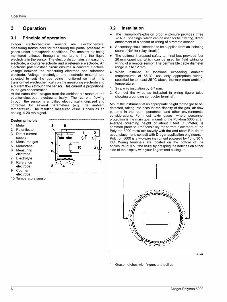
3.1 Principle of operationDräger electrochemical sensors are electrochemical measuring transducers for measuring the partial pressure of gases under atmospheric conditions. The ambient air being monitored diffuses through a membrane into the liquid electrolyte in the sensor. The electrolyte contains a measuring electrode, a counter-electrode and a reference electrode. An electronic potentiostatic circuit ensures a constant electrical voltage between the measuring electrode and reference electrode. Voltage, electrolyte and electrode material are selected to suit the gas being monitored so that it is transformed electrochemically on the measuring electrode and a current flows through the sensor. This current is proportional to the gas concentration.At the same time, oxygen from the ambient air reacts at the counter-electrode electrochemically. The current flowing through the sensor is amplified electronically, digitized and corrected for several parameters (e.g. the ambient temperature). The resulting measured value is given as an analog, 4-20 mA signal.
Design principle1 Meter2 Potentiostat3 Direct current
supply4 Measured gas5 Membrane6 Measuring
electrode7 Electrolyte8 Reference
electrode9 Counter
electrode10 Temperature sensor
3.2 InstallationThe flameproof/explosion proof enclosure provides three ¾" NPT openings, which can be used for field wiring, direct attachment of a sensor or wiring of a remote sensor.Secondary circuit intended to be supplied from an isolating source (N/A for relay circuits).The optional increased safety terminal box provides four 20 mm openings, which can be used for field wiring or wiring of a remote sensor. The permissible cable diameter range is 7 to 12 mm.When installed at locations exceeding ambient temperatures of 55 °C, use only appropriate wiring, specified for at least 25 °C above the maximum ambient temperature.
1. Strip wire insulation by 5-7 mm.2. Connect the wires as indicated in wiring figure (also
showing grounding conductor terminal).
Mount the instrument at an appropriate height for the gas to be detected, taking into account the density of the gas, air flow patterns in the room, personnel, and other environmental considerations. For most toxic gases, where personnel protection is the main goal, mounting the Polytron 5000 at an average breathing height of about 5 feet (1.5 meter) is common practice. Responsibility for correct placement of the Polytron 5000 rests exclusively with the end user; if in doubt about placement, consult with Dräger application engineers.Polytron 5000 is a two-wire instrument powered by 16 to 30 V DC. Wiring terminals are located on the bottom of the enclosure; pull out the bezel by grasping the notches on either side of the display with your fingers and pulling up.
1 Grasp notches with fingers and pull up.
6 Dräger Polytron 5000

Operation
Connect the wires as shown below.
Secondary circuit intended to be supplied from an isolating source.
Tightening torque
Tightening torque and wire size for field wiring terminals
In case of optional increased safety terminal box, securely screw the transmitter onto the e-box using 4 screws with a tightening torque of 8 Nm.
3.3 Installing the sensorThe Polytron 5000 sensor connector is keyed and can only be installed one way. Use only DrägerSensors in this instrument. To install the sensor, see the following figure for details:
1 Sensor housing2 Sensor3 Set screw4 Sensor cover1. Loosen the set screw in the stainless steel sensor cover.2. Unscrew the stainless steel sensor cover at the end of the
sensor housing.3. Insert the ribbon cable connector into the socket in the
DrägerSensor®1. 4. Push the DrägerSensor into the sensor housing.5. Screw the stainless steel sensor cover back on.6. Tighten the set screw to secure the sensor cover.7. Allow the sensor to warm-up according to the sensor data
sheets.Always test a newly-installed sensor with target gas to verify proper operation.When installed at locations exceeding ambient temperatures of 55 °C, use only appropriate wiring specified for at least 25 °C above the maximum ambient temperature.
Part TQ Lb. In. TQ Nmlid min. 266 min. 30
sensors min. 266 min. 30
plugs min. 266 min. 30
conduit hubs min. 443 min. 50
ElectronicTQ Lb. In. Wire Size AWG Wire Size mm2
All field wiring terminals4.4 - 7.0
(0.5 - 0.8 Nm)
24 - 12 0.2 - 2.5
1) DrägerSensor® is a registered trademark from Dräger
Dräger Polytron 5000 7

Operation
3.4 Replacing the sensor1. Loosen the set screw in the sensor cover.2. Unscrew the stainless steel sensor cover at the end of the
sensor housing.3. Pull the ribbon cable out of the sensor connector and
remove the old sensor.4. Insert the ribbon cable connector into the socket of the
replacement DrägerSensor.5. Push the DrägerSensor into the sensor housing.6. Screw the stainless steel sensor cover back on.7. Tighten the set screw to secure the sensor cover.8. Always test a newly-installed sensor with target gas to
verify proper operation.
3.5 MenuIn the standard operating mode, the gas concentration of the target gas will be displayed. To access the software menu, tap the magnetic wand once against the glass viewport above the Down arrow. The display shows the first menu item, Zero Adj. The displays flashes ‘-0-’, ‘Adj’, and then shows the target gas concentration.
3.5.1 Menu navigationTap the magnetic wand over the Up and Down arrows to scroll through the menu selections. If the magnetic wand is held over the switch for > 0.5 second, this will be considered multiple taps and the menu will scroll. When you reach the last item Password Adj, the menu will bottom-out, and you will have to use the Up arrow to scroll back up through the menu. The active menu item as well as its current value or status will flash on the display as it scrolls.
3.5.2 Changing parameter values/statusTo enter a new value, or change a status, tap OK with the magnetic wand when the desired menu item is displayed. The current value or status will flash to indicate a change to data
entry mode. The Up and Down arrows allow you to adjust the value of a numerical parameter or to toggle between preset choices. Once the display shows the desired value or choice, tap OK to validate the new parameter. This will take you back to the menu, where you can scroll to another menu item, if desired.
3.5.3 Exiting the MenuTo get back into the standard measurement mode, just scroll to the gas concentration menu item at the top of the menu. The actual gas concentration will be displayed.
3.6 Menu items
3.6.1 Sensor lockUpon power up, the Polytron 5000 checks to see if the correct sensor is installed in order to prevent accidental installation of the wrong sensor type. If the correct sensor type is installed, the software goes directly to measurement mode, displaying the gas concentration (see Section 3.6.2 on Page 9).If the installed sensor differs from the sensor installed previously, the message ‘sns’, ‘loc’, ‘on’ (sensor lock on) will flash. You then have two choices: install a sensor of the correct type, or verify that you are purposely changing to a different sensor. To verify the switch to a different sensor, hold the magnetic wand over OK. The flashing message will change to ‘sns’, ‘loc’, ‘5’, then to ‘sns’, ‘loc’, ‘4’, counting down from 5 to 1. You must hold the magnetic wand on OK during the entire countdown. If you remove the magnet at any time during the countdown, ‘sns’, ‘loc’, ‘on’ will begin flashing again. After counting down to ‘sns’, ‘loc’, ‘1’, the instrument will switch to the measurement mode, accepting the new sensor type.
8 Dräger Polytron 5000
Operation
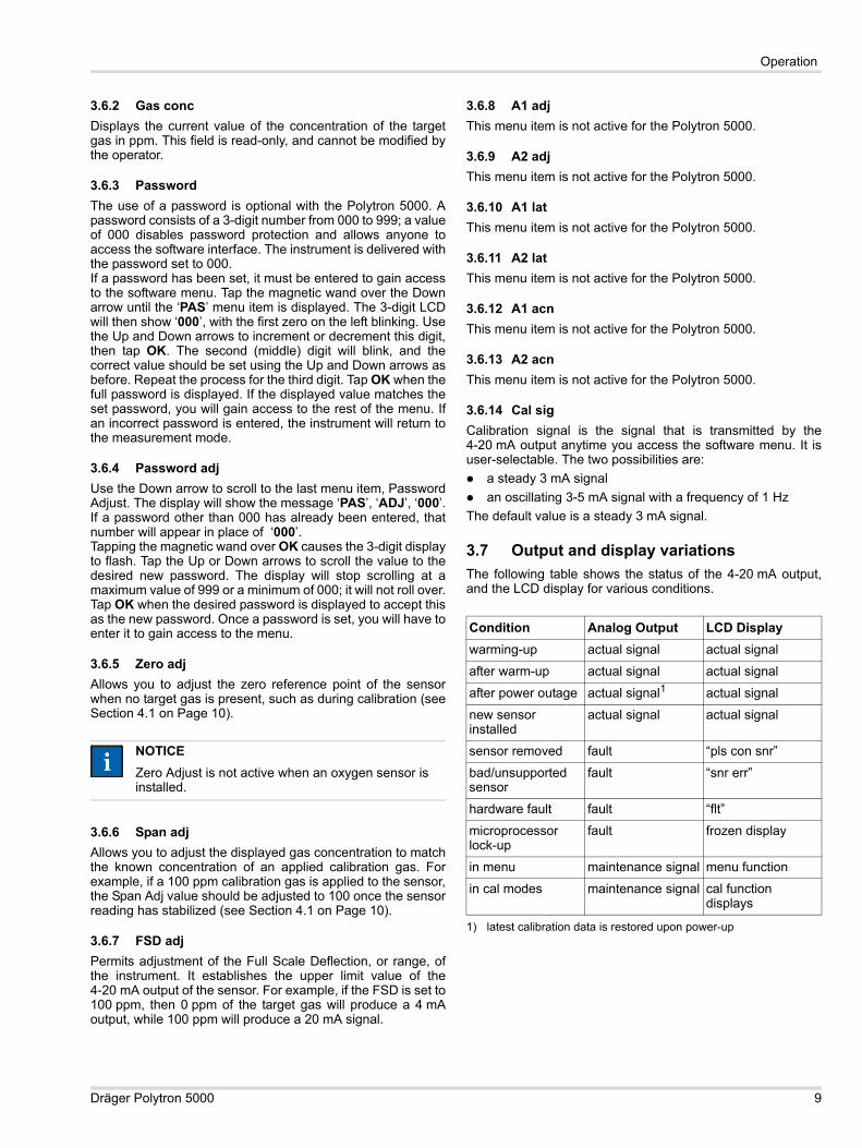
3.6.2 Gas concDisplays the current value of the concentration of the target gas in ppm. This field is read-only, and cannot be modified by the operator.
3.6.3 PasswordThe use of a password is optional with the Polytron 5000. A password consists of a 3-digit number from 000 to 999; a value of 000 disables password protection and allows anyone to access the software interface. The instrument is delivered with the password set to 000.If a password has been set, it must be entered to gain access to the software menu. Tap the magnetic wand over the Down arrow until the ‘PAS’ menu item is displayed. The 3-digit LCD will then show ‘000’, with the first zero on the left blinking. Use the Up and Down arrows to increment or decrement this digit, then tap OK. The second (middle) digit will blink, and the correct value should be set using the Up and Down arrows as before. Repeat the process for the third digit. Tap OK when the full password is displayed. If the displayed value matches the set password, you will gain access to the rest of the menu. If an incorrect password is entered, the instrument will return to the measurement mode.
3.6.4 Password adjUse the Down arrow to scroll to the last menu item, Password Adjust. The display will show the message ‘PAS’, ‘ADJ’, ‘000’.If a password other than 000 has already been entered, that number will appear in place of ‘000’.Tapping the magnetic wand over OK causes the 3-digit display to flash. Tap the Up or Down arrows to scroll the value to the desired new password. The display will stop scrolling at a maximum value of 999 or a minimum of 000; it will not roll over.Tap OK when the desired password is displayed to accept this as the new password. Once a password is set, you will have to enter it to gain access to the menu.
3.6.5 Zero adjAllows you to adjust the zero reference point of the sensor when no target gas is present, such as during calibration (see Section 4.1 on Page 10).
3.6.6 Span adjAllows you to adjust the displayed gas concentration to match the known concentration of an applied calibration gas. For example, if a 100 ppm calibration gas is applied to the sensor, the Span Adj value should be adjusted to 100 once the sensor reading has stabilized (see Section 4.1 on Page 10).
3.6.7 FSD adjPermits adjustment of the Full Scale Deflection, or range, of the instrument. It establishes the upper limit value of the 4-20 mA output of the sensor. For example, if the FSD is set to 100 ppm, then 0 ppm of the target gas will produce a 4 mA output, while 100 ppm will produce a 20 mA signal.
3.6.8 A1 adjThis menu item is not active for the Polytron 5000.
3.6.9 A2 adjThis menu item is not active for the Polytron 5000.
3.6.10 A1 latThis menu item is not active for the Polytron 5000.
3.6.11 A2 latThis menu item is not active for the Polytron 5000.
3.6.12 A1 acnThis menu item is not active for the Polytron 5000.
3.6.13 A2 acnThis menu item is not active for the Polytron 5000.
3.6.14 Cal sigCalibration signal is the signal that is transmitted by the 4-20 mA output anytime you access the software menu. It is user-selectable. The two possibilities are:
a steady 3 mA signalan oscillating 3-5 mA signal with a frequency of 1 Hz
The default value is a steady 3 mA signal.
3.7 Output and display variationsThe following table shows the status of the 4-20 mA output, and the LCD display for various conditions.
NOTICEZero Adjust is not active when an oxygen sensor is installed.
ii
Condition Analog Output LCD Displaywarming-up actual signal actual signal
after warm-up actual signal actual signal
after power outage actual signal1
1) latest calibration data is restored upon power-up
actual signal
new sensor installed
actual signal actual signal
sensor removed fault “pls con snr”
bad/unsupported sensor
fault “snr err”
hardware fault fault “flt”
microprocessor lock-up
fault frozen display
in menu maintenance signal menu function
in cal modes maintenance signal cal function displays
Dräger Polytron 5000 9

Maintenance
4 MaintenancePrior to calibration, each sensor must be allowed to warm up for the length of time specified in the sensor data sheet. During this time the sensor is capable of detecting the target gas, but its performance will deviate from specifications. Please see sensor data sheet for details.
4.1 Calibration procedure for toxic gases For oxygen sensor see Section 4.2 on Page 11.Calibration of this instrument must be performed at regular intervals as detailed in the sensor data sheet.
1 Regulator2 Calibration gas cylinder3 Calibration adapter
4.1.1 Zero calibration1. Attach the pressure regulator to the nitrogen (N2) or Zero
Air calibration gas cylinder. 2. Fit the calibration adapter tightly to the end of the sensor.3. Turn the gas on.
4. Scroll through software menu to Zero Adj and tap OK. The current zero value will be displayed.
5. Wait for the zero to stabilize.
6. Trim the stabilized value to zero on the display using the Up and Down arrows.
7. Accept the value by tapping OK with the magnetic wand.8. Turn off the gas flow and remove the calibration adapter
from the sensor
.
4.1.2 Span calibration1. Attach the pressure regulator to the calibration gas cylin-
der. 2. Fit the calibration adapter tightly to the end of the sensor.3. Turn the gas flow on.
4. Scroll through software menu to Span Adj and tap OK. The span value will be displayed.
5. Wait for the span value to stabilize.6. Trim the stabilized value to the calibration gas
concentration using the Up and Down arrows. 7. Accept the value by tapping OK with the magnetic wand.8. Turn off the gas flow and remove the calibration adapter
from the sensor.
NOTICEAllow the gas to flow for at least three minutes before proceeding.
ii
NOTICEAmbient air can be used to zero the sensor instead of nitrogen or Zero Air if the area is known to be free of the target gas or any gas to which the sensor may be cross-sensitive (as listed on the sensor data sheet). In this case, no cylinder or calibration adapter is needed for the zero calibration.
NOTICEAllow the gas to flow for at least three minutes before proceeding.
ii
ii
10 Dräger Polytron 5000

Disposal of electrical and electronic equipment
4.2 Calibration procedure for oxygen
4.2.1 Zero calibrationZero calibration is not required for the oxygen version of the Polytron 5000.
4.2.2 Span calibrationThe span calibration of an oxygen sensor requires oxygen calibration gas or ambient air. Normally a cylinder containing 20.9 % O2 is used to match the atmospheric concentration.
1. Fit the calibration adapter tightly to the end of the sensor if calibrating with a cylinder containing oxygen. Alternatively, if you want to calibrate the span using ambient air, leave the adapter off and skip the next two steps.
2. Attach the pressure regulator to the calibration gas cylinder containing 20.9 % O2.
3. Turn the gas flow on.
4. Scroll through software menu to Span Adj.5. Wait for the signal to stabilize.6. Trim the stabilized value to the calibration gas
concentration (normally 20.9 %) using the Up and Down arrows.
7. Accept the value by tapping OK with the magnetic wand.8. Turn off the gas flow and remove the calibration adapter
from the sensor.
4.3 Error messages
5 Disposal of electrical and electron-ic equipment
NOTICEAllow the gas to flow for at least three minutes before proceeding.
Error Code Condition Solutionpls con snsr no sensor is
connectedconnect sensor
sensor connection is bad
check to ensure sensor is seated in connector
snr err unsupported sensor is connected or sensor EEPROM data is corrupted
install supported sensor
flt hardware fault replace electronics
AFE err wrong software version installed in analog front end (AFE)
install most recent AFE software
defective AFE replace electronics
AFE out AFE microcontroller is out of its socket or not installed
check microcontroller
defective AFE replace electronics
ii
EC-wide regulations for the disposal of electrical and electronic equipment, which have been defined in the EU Directive 2002/96/EC and in national laws, have been effective since August 2005 and apply to this device. Common household appliances can be disposed of using special collecting and recycling facilities. However, as this device has not been registered for household usage, it must not be disposed of through these means. The device can be returned to your national Dräger Sales Organization for disposal. Please do not hesitate to contact Dräger if you have any further questions on this issue.
Dräger Polytron 5000 11
Technical data
6 Technical data
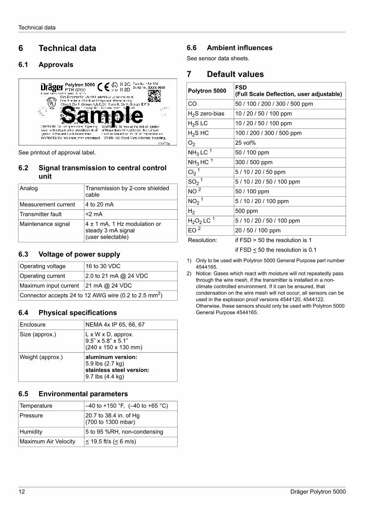
6.1 Approvals
See printout of approval label.
6.2 Signal transmission to central control unit
6.3 Voltage of power supply
6.4 Physical specifications
6.5 Environmental parameters
6.6 Ambient influencesSee sensor data sheets.
7 Default values
Analog Transmission by 2-core shielded cable
Measurement current 4 to 20 mA
Transmitter fault <2 mA
Maintenance signal 4 ± 1 mA, 1 Hz modulation or steady 3 mA signal (user selectable)
Operating voltage 16 to 30 VDC
Operating current 2.0 to 21 mA @ 24 VDC
Maximum input current 21 mA @ 24 VDC
Connector accepts 24 to 12 AWG wire (0.2 to 2.5 mm2)
Enclosure NEMA 4x IP 65, 66, 67
Size (approx.) L x W x D, approx. 9.5” x 5.8” x 5.1” (240 x 150 x 130 mm)
Weight (approx.) aluminum version:5.9 lbs (2.7 kg)stainless steel version:9.7 lbs (4.4 kg)
Temperature –40 to +150 °F, (–40 to +65 °C)
Pressure 20.7 to 38.4 in. of Hg (700 to 1300 mbar)
Humidity 5 to 95 %RH, non-condensing
Maximum Air Velocity < 19.5 ft/s (< 6 m/s)
SamplePolytron 5000 FSD
(Full Scale Deflection, user adjustable)CO 50 / 100 / 200 / 300 / 500 ppm
H2S zero-bias 10 / 20 / 50 / 100 ppm
H2S LC 10 / 20 / 50 / 100 ppm
H2S HC 100 / 200 / 300 / 500 ppm
O2 25 vol%
NH3 LC 1
1) Only to be used with Polytron 5000 General Purpose part number 4544165.
50 / 100 ppm
NH3 HC 1 300 / 500 ppm
Cl2 1 5 / 10 / 20 / 50 ppm
SO2 1 5 / 10 / 20 / 50 / 100 ppm
NO 2
2) Notice: Gases which react with moisture will not repeatedly pass through the wire mesh, if the transmitter is installed in a non-climate controlled environment. If it can be ensured, that condensation on the wire mesh will not occur; all sensors can be used in the explosion proof versions 4544120, 4544122. Otherwise, these sensors should only be used with Polytron 5000 General Purpose 4544165.
50 / 100 ppm
NO2 1 5 / 10 / 20 / 100 ppm
H2 500 ppm
H2O2 LC 1 5 / 10 / 20 / 50 / 100 ppm
EO 2 20 / 50 / 100 ppm
Resolution: if FSD > 50 the resolution is 1
if FSD < 50 the resolution is 0.1
12 Dräger Polytron 5000

Order list
8 Order list
8.1 Sensors
8.2 Accessories
8.3 Spare parts
Description Part Number
Polytron 5000, DS d A 4544120
Polytron 5000, DS d S 4544122
Polytron 5000, DS d A General Purpose 4544165
Description Part Number
DrägerSensor CO 6809605
DrägerSensor H2S 6810435
DrägerSensor H2S LC 6809610
DrägerSensor H2S HC 6809710
DrägerSensor O2 LS 6809630
DrägerSensor H2 6809685
DrägerSensor NH3 LC 68096801
1) Only to be used with Polytron 5000 General Purpose part number 4544165.
DrägerSensor NH3 HC 68096451
DrägerSensor Cl2 68096651
DrägerSensor SO2 68096601
DrägerSensor NO 68096252
2) Notice: Gases which react with moisture will not repeatedly pass through the wire mesh, if the transmitter is installed in a non-climate controlled environment. If it can be ensured, that condensation on the wire mesh will not occur; all sensors can be used in the explosion proof versions 4544120, 4544122. Otherwise, these sensors should only be used with Polytron 5000 General Purpose 4544165.
DrägerSensor NO2 68096551
DrägerSensor H2O2 LC 68097051
DrägerSensor EO 68107402
Description Part Number
Pipe Mount Kit 4544198
Magnet with Key Chain 4544101
Splash Guard 6812510
Calibration Adapter PE 4509314
Calibration Adapter PE, Europe 6806978
Calibration Adapter Viton 6810536
Calibration Kit (includes carrying case, calibration adapter 4509314, 500 cc/min cylinder regulator 4557020 and 100 % N2 103 L @ 1000 PSI nitrogen / zero gas cylinder)
4594620
Calibration Gases on request
Description Part Number
Bezel Polytron 5000 4544184
PCB Main Polytron 5000 4544185
PCB Filter Polytron 5000 4544252
Sensor Housing Complete 4544189
Sensor Cap 4544190
Dräger Polytron 5000 13

Order list
14 Dräger Polytron 5000


Draeger Safety, Inc. 101 Technology Drive Pittsburgh, PA 15275-1057 USA Phone +1 412 787 - 83 83 Fax +1 412 7 87 - 22 07 www.draeger.com
4544285 © Draeger Safety, Inc. Edition 01 - March 2011 Subject to alteration