INSTRUCTIONS FOR INSTALLATION AND USE SAUNA HEATER … · 500 mm 6 3 B 3 B C C C C A 1000 mm...
13
37 We wish you many hours of relaxation and pleasure in your sauna. Please read the instructions beneath very carefully in order to find out how the sauna works. ATTENTION: The sauna heater must be connected to the power supply by a qualified electrician and in compliance with current regulations. INSTALLATION OF THE HEATER For information about how to install the heater, please see page 3. When mounting the heater, please take note of the following: - Follow the given instructions - Wood panelling is the approved material for walls and ceiling in the sauna room. - Check that the wall panelling is secured where the screws will be fastened. - Only one sauna unit may be installed in a sauna room. - The heater must not be surrounded by a compact heater guard. Before installing the heater, please check the following: - That the following parts have been delivered: heater, stones. - That the voltage of the heater is correct. - That the kW of the heater corresponds with the size (m3 ) of the sauna room. See table 1. - That the minimum construction distances in fig. 2 are strictly followed. MOUNTING THE SAUNA HEATER (See fig 2) Drill the four screw holes using a 3,5 mm drill bit. The screw head should be approx. 3 mm from the wall surface.Make sure that the screws are fastened through the sauna room soft wood lining into a backing board to hold the heater. Hang the heater on the screws. Tighten the lower screws in order to lock the heater in position. Re-chech your distances from the heater to combustible materials to make sure the stipulated minimum distances are followed. INSTRUCTIONS FOR INSTALLATION AND USE SAUNA HEATER 1712-30-1718 1712-45-1718 1712-60-1718 1712-80-1718 1712-90-1718 7013513 314 SKSM 14 N
Transcript of INSTRUCTIONS FOR INSTALLATION AND USE SAUNA HEATER … · 500 mm 6 3 B 3 B C C C C A 1000 mm...

37
We wish you many hours of relaxation and pleasure in your sauna. Please read the instructions beneath very carefully in order to find out how the sauna works.
ATTENTION: The sauna heater must be connected to the power supply by a qualified electrician and in compliance with current regulations.
INSTALLATION OF THE HEATERFor information about how to install the heater, please see page 3. When mounting the heater, please take note of the following:- Follow the given instructions- Wood panelling is the approved material for walls and ceiling in the sauna room.- Check that the wall panelling is secured where the screws will be fastened.- Only one sauna unit may be installed in a sauna room.- The heater must not be surrounded by a compact heater guard.
Before installing the heater, please check the following:- That the following parts have been delivered: heater, stones.- That the voltage of the heater is correct.- That the kW of the heater corresponds with the size (m3 ) of the sauna room. See table 1.- That the minimum construction distances in fig. 2 are strictly followed.
MOUNTING THE SAUNA HEATER (See fig 2)Drill the four screw holes using a 3,5 mm drill bit. The screw head should be approx. 3 mm from the wall surface.Make sure that the screws are fastened through the sauna room soft wood lining into a backing board to hold the heater.Hang the heater on the screws. Tighten the lower screws in order to lock the heater in position. Re-chech your distances from the heater to combustible materials to make sure the stipulated minimum distances are followed.
INSTRUCTIONS FOR INSTALLATION AND USE
SAUNA HEATER 1712-30-1718 1712-45-1718 1712-60-1718 1712-80-1718 1712-90-1718
7013513314 SKSM 14 N

38
3
1 2
4
3
5
2
1
1
2
5
3
4
Fig 4
CHOOSING LEFT OR RIGHT CONTROLSThe unit is supplied with a timer and thermostat installed on the front side of the unit. If it is necessary to move the controls to the right or to the left, this should be done by a qualified electrician when the heater is installed (see fig. 4).1.Turn the sauna unit upside down, remove the bottom plate.2.Remove the knobs (3) for the thermostat (2) and the timer (1) by pulling them straight out.3.Remove the screws holding the timer and thermostat.4.Remove the sectional plate from the side of the unit.5.Move the timer (1) and the thermostat (2) to the side. The dial plate (5) is separately mounted using the thermostat and timer mounting screws.6.Press the knobs into place.
5 5
4
4
21
1
1
A7
A
min500 mm
6
3B
3B
C
C
C
C A
1000 mm
Recommended sauna room ventilation
1. Sauna room 3. Electric sauna heater 5. Exhaust flue or channel2. Washroom 4. Exhaust valve 6. Door to the sauna room7. A ventilation valve can be installed here to be kept closed while the sauna is heated and during bathing.Inlet vent can be positioned in the A zone. Make sure the incoming fresh air will not interfere with (i.e. cool down) the sauna heater's thermostat near the ceiling.The B zone serves as the incoming air zone, if the sauna room isn't fitted with forced ventilation. In this case, the exhaust valve is installed min 1m higher than the inlet valve.DO NOT ISTALL INLET VALVE WITHIN ZONE C, IF THE SAUNA HEATER'S CONTROL THERMOSTAT IS LOCATED AT THE SAME ZONE.
39
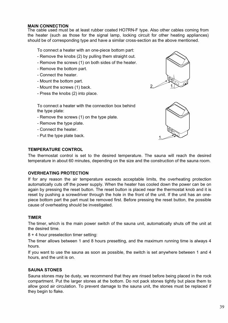
To connect a heater with an one-piece bottom part:- Remove the knobs (2) by pulling them straight out.- Remove the screws (1) on both sides of the heater.- Remove the bottom part.- Connect the heater.- Mount the bottom part.- Mount the screws (1) back.- Press the knobs (2) into place.
To connect a heater with the connection box behind the type plate:- Remove the screws (1) on the type plate.- Remove the type plate.- Connect the heater.- Put the type plate back.
1.
1.
2.
MAIN CONNECTIONThe cable used must be at least rubber coated HO7RN-F type. Also other cables coming from the heater (such as those for the signal lamp, locking circuit for other heating appliances) should be of corresponding type and have a similar cross-section as the above mentioned.
TEMPERATURE CONTROLThe thermostat control is set to the desired temperature. The sauna will reach the desired temperature in about 60 minutes, depending on the size and the construction of the sauna room.
OVERHEATING PROTECTIONIf for any reason the air temperature exceeds acceptable limits, the overheating protection automatically cuts off the power supply. When the heater has cooled down the power can be on again by pressing the reset button. The reset button is placed near the thermostat knob and it is reset by pushing a screwdriver through the hole in the front of the unit. If the unit has an one-piece bottom part the part must be removed first. Before pressing the reset button, the possible cause of overheating should be investigated.
TIMERThe timer, whi ch is the main power switch of the sauna unit, automatically shuts off the unit at the desired time.8 + 4 hour preselection timer setting:The timer allows between 1 and 8 hours presetting, and the maximum running time is always 4 hours.If you want to use the sauna as soon as possible, the switch is set anywhere between 1 and 4 hours, and the unit is on.
SAUNA STONESSauna stones may be dusty, we recommend that they are rinsed before being placed in the rock compartment. Put the larger stones at the bottom. Do not pack stones tightly but place them to allow good air circulation. To prevent damage to the sauna unit, the stones must be replaced if they begin to flake.

40
Minimum distances (mm)
D D
E
Max
350
MIN.mm
min
20
min 30
min
30
150
370
Minimum distances to themounting bracket (mm)
Drill 3,5 mm
Screws 6 x 40 (2 pcs)Screws 6 x 16 (2 pcs)
B
J3
Table 1
Fig. 2
Fig. 3
K
A A D
min
20
min 30m
in 2
0min 30
F
min
190
0
(mm) (mm)
Sauna room Minimum distance to: Minimum distance for Stone Supply connections the wall bracket Volume Height Side In front of Ceiling Floor Niche Cable size wall HO7RN-F A D F K E B J 3N~ 1N~ kW m mm mm mm m m mm mm mm mm kg Heater Heater 3,0 2 - 4 1900 30 50 1200 120 540 50 390 15 5 x 1,5mm2 3 x 2,5mm2
4,5 3 - 6 1900 50 80 1200 120 580 70 390 15 5 x 1,5mm2 3 x 4mm2
6,0 5 - 9 1900 70 100 1250 120 650 90 390 23 5 x 1,5mm2 3 x 10mm2
8,0 8 - 13 1900 100 150 1250 120 750 120 390 23 5 x 2,5mm2 3 x 10mm2
9,0 9 - 14 1900 100 150 1250 120 - 120 390 23 5 x 2,5mm2 -

41
3 - 8 kW heater 9 kW heater
3 - 4,5 kW heater
1 2 3 4 5 6
321
N L1 L2 L3 400V 3N~
a1
a1
a1
b0
b0
b0
a
ba
ab
b
4,56,08,0
1,2,31,2,3
1,2,3
OYKS 3
OLHC 1
U 1 1 RV 2 2 SW 3 3 T
8kW2,5mm
2
230V
7 8 9 10
M
7-8: - Merkkilamppu, Märklamp Signallampa, Signallamp. Kontrolleuchte, Luz de snalacion
9-10:- Sähkölämmityksen vuorottelu. - El.förregling av annan el.förbrukare. - Control of el.heating. - Steuerkontakt für Verriegelung anderer el.Verbraucher. - Elektrikütte vaeldumine - Alternacion de la calefaccion electrica.
Teho, VöimsusEffekt, Input, Leistung, Potencia
kW
Lämpövastukset, Värmeelement, TennidHeating element, HeizelementResistores Termicos
230V354 SKSM 3-2 J
1,2,33,0
SEPC 64 2000W
SEPC 63 1500W
SEPC 62 1000W
SEPC 65 2670W
~
1 2 3 4 5 6
321
N L1 L2 L3 400V 3N~
Teho, EffektInput, Leistung,Vöimus, Potencia
kW
a1
a1
a1
b0
b0
b0
a
ba
ab
b
354 SKSM 3-3 C
19,0
SEPC 65C 3300W
SEPC 65B 3000W
SEPC 65 2670W
OYKS 3
OLHC 1
U 1 1 RV 2 2 SW 3 3 T
230V
7 8 9 10
M
2 3
2,5m
m2
2,5m
m2
7-8: - Merkkilamppu, Märklamp Signallampa, Signallamp. Kontrolleuchte, Luz de snalacion
9-10:- Sähkölämmityksen vuorottelu. - El.förregling av annan el.förbrukare. - Control of el.heating. - Steuerkontakt für Verriegelung anderer el.Verbraucher. - Elektrikütte vaeldumine - Alternacion de la calefaccion electrica.
~
Lämpövastukset, Värmeelement, TennidHeating element, HeizelementResistores Termicos
230V
123
Teho, EffektInput, LeistungVöimus, Potencia
kW
a1
a1
a1
b0
b0
b0
a
b
a
ab
b
M
354 SKSM 106 D
1,2,33,04,5 1,2,3
SEPC 63 1500W
SEPC 62 1000W
11
12
21
22
31
32
1 3 5 21 A1
2 4 6 22 A2
987 10
1 2 3 4 5 6
LN230V 1N~
1 2 3 4 5 6
L3N L1 L2400V 3N~
7-8: - Merkkilamppu, Märklamp Signallampa, Signallamp. Kontrolleuchte, Luz de snalacion
9-10:- Sähkölämmityksen vuorottelu. - El.förregling av annan el.förbrukare. - Control of el.heating. - Steuerkontakt für Verriegelung anderer el.Verbraucher. - Elektrikütte vaeldumine - Alternacion de la calefaccion electrica.
~
Lämpövastukset, Värmeelement, TennidHeating element, HeizelementResistores Termicos
230V

42
1 2 3 4 5 6
321
N L1 L2 L3
380V 3N~ / 415V 3N~
Teho, EffektInput, Leistung
kW
Lämpövastukset, Värmeelement,Heating element, Heizelement 230V / 240V
a1
a1
a1
b0
b0
b0
a
ba
ab
b
354 SK 110/1 A
1 2 39,0
SEPC 65C 3300W
SEPC 65B 3000W
SEPC 65 2670W
OYKS 3
OLHC 1
U 1 1 RV 2 2 SW 3 3 T
8kW2,5mm2 7-8: Merkkivalo/Signallampa/
Signallamp/Kontrolleuchte.
9-10: Sähkölämmityksen ohjaus. El.förregling av annan el.förbrukare. Control of el.heating. Steuerkontakt für Verrie- gelung anderer el.Verb- raucher.
220V
7 8 9 10
M
240V
1 2 3 4 5 6
321
N L1 L2 L3
380V 3N~ / 415V 3N~
Teho, EffektInput, Leistung
kW
Lämpövastukset, Värmeelement,Heating element, Heizelement 230V / 240V
a1
a1
a1
b0
b0
b0
a
ba
ab
b
354 SKSM 110 C
1,2,33,04,56,08,0
1,2,31,2,3
1,2,3
SEPC 64 2000W
SEPC 63 1500W
SEPC 62 1000W
SEPC 65 2670W
OYKS 3
OLHC 1
U 1 1 RV 2 2 SW 3 3 T
8kW2,5mm2 7-8: Merkkivalo/Signallampa/
Signallamp/Kontrolleuchte.
9-10: Sähkölämmityksen ohjaus. El.förregling av annan el.förbrukare. Control of el.heating. Steuerkontakt für Verrie- gelung anderer el.Verb- raucher.
220V
7 8 9 10
M
240V

43
Teho, EffektInput, LeistungVöimsus kW
Lämpövastukset, Värmeelement, TennidHeating element, Heizeelement 230V-240V
SEPC 62 SEPC 63 SEPC 64 SEPC 65 1000W 1500W 2000W 2670W
1,2,3 1,2,3 1,2,3 1,2,3
3,04,56,08,0
123
a1
a1
a1
b0
b0
b0
a
b
a
ab
b
M 11
12
21
22
31
32
1 3 5 21 A1
2 4 6 22 A2
1 2 3 4 5 6
LN
230V-240V 1N~
1 2 3 4 5 6
L3N L1 L2
400V-415V 3N~354 SKSM 127 E
1712-30-1718, 1712-45-1718, 1712-60-1718, 1712-80-1718
Teho Jännite Sulake Kiukaan liitäntä johto Effekt Spänning Säkring Ugnens anslutnings kabel Input Voltage Fuse Cables to Heater Leistung Spannung Sicherung Kabel zum Ofen HO7RN-F
kW V A mm2
3 230 16 3 x 2,5 4,5 230 20 3 x 4,0 6 230 35 3 x 10 8 230 35 3 x 10 3 240 16 3 x 2,5 4,5 240 20 3 x 4,0 6 240 35 3 x 10 8 240 35 3 x 10

97
INSTRUCCIONES DE INSTALACIÓN Y USO
ESTUFA ELÉCTRICA: 1712-30-1718 1712-45-1718 1712-60-1718 1712-80-1718 1712-90-1718
INSTALACIÓN DE LA ESTUFA Es importante recordar las siguientes instrucciones al realizar la instalación de la estufa: - Observe las medidas de construcción indicadas. - Recomendamos usar paneles de madera como material de construcción de las paredes y el techo de la
sauna. - Asegúrese de que las partes de las paredes paneladas situadas cerca de los tornillos de fijación de la
estufa hayan sido reforzadas. Si no es así, tienen que ser reforzadas. - Sólo se puede instalar una estufa en la sauna. - Según las regulaciones vigentes, la conexión de la estufa a la red eléctrica sólo puede ser relizada por
un electricista autorizado. - Antes de enchufar la estufa, asegúrese de que el cuarto de vapor de la sauna está listo para ser usado. CONEXIÓN DE LA ESTUFA A LA RED ELÉCTRICA La estufa debe ser conectada a la red eléctrica de forma semifija, con la ayuda de un cable de goma del tipo H07RN-F. Los demás cables que salen de la estufa (luz de señalización, alternación de la calefacción eléctrica) tienen que ser del mismo tipo, y sus superficies transversales tienen corresponder a las superficies transversales del cable de conexión. LAS PIEDRAS DE LA ESTUFA Recomendamos lavar las piedras antes de colocarlas en la estufa. Coloque las piedras más grandes al fondo del depósito de piedras, y las más pequeñas sobre ellas. Deje un poco de espacio entre las piedras para permitir la circulación de aire entre ellas. Las piedras deben ser esparcidas y colocadas ligeramente entre los elementos de calefacción. Las piedras tienen que cubrir los elementos de calefacción completamente. Es necesario reemplazar las piedras al menos al observar que han empezado a desintegrarse, porque esto interrumpe la circulación de aire dentro de la estufa. Al reemplazar las piedras, siempre use piedras de alta calidad diseñadas para uso en estufas de baños de vapor. EL TERMOSTATO DE LA SAUNA Y EL RESTRICTOR TÉRMICO Al girar el termostato de la sauna en el sentido de las agujas del reloj, la temperatura de la sauna sube. La manera más fácil de encontrar la temperatura deseada es girando el termostato a su posición máxima, y dejando que la temperatura suba a la temperatura deseada. Después de haber alcanzado la temperatura deseada, se baja la temperatura girando el termostato lentamente en la dirección opuesta hasta que se pare, y se deja en esa posición. Si después de esta operación resulta necesario ajustar la temperatura, tiene que girar el termostato poco a poco, comprobando el efecto que tiene. El restrictor térmico, situado en el sensor, interrumpe toda la potencia térmica de la estufa si la temperatura de la estufa sube a un nivel peligroso para las piezas de madera de la sauna. Después de que la temperatura haya vuelto a bajar, se puede devolver a su posición el restrictor, pero antes de esto siempre es necesario averiguar la causa de la avería. EL USO DEL TEMPORIZADOR El temporizador funciona como el interruptor de control de la estufa. Sus posiciones de puesta en marcha, desde la posición 0 y avanzando en sentido de las agujas del reloj, son las siguientes: 1. La posición 0, en que la corriente está desactivada. 2. La zona de 0…4h, en la que todos los resistores se calientan a toda capacidad y el termostato de la
sauna regula la temperatura. 3. La zona de 0…8h, la zona de preselección en el que la sauna no es calentada. En la zona de tiempo de preselección (0…8h), se selecciona el tiempo después del cual se quiere iniciar el calentamiento de la sauna (note que el tiempo de calentamiento de la sauna es de aproximadamente 1 hora). El motor del temporizador siempre gira el manubrio automáticamente a la posición 0. También es posible desconectar la corriente desde la estufa antes de que el tiempo de funcionamiento haya terminado. En este caso, gire el temporizador manualmente en sentido opuesto a las agujas del reloj hasta llegar a la posición 0.
7014144 314 SKSM 119 B

98
MEDIDAS DE INSTALACIÓN MÍNIMAS (mm) DE LA ESTUFA Potencia
Cuarto de vapor
Distancias mínimas de la estufa
Distancias mínimas del soporte de pared
Piedras
kW
Volumen
m³
Altura
mm
De la superficie
lateral A
mm
De la superficie
frontal D
mm
Al techo
F mm
Al suelo
K mm
B mm
J
mm
kg (aprox.)
3,0 2 - 4 1900 30 50 1200 120 50 390 15 4,5 3 – 6 1900 50 80 1200 120 70 390 15 6,0 5 – 9 1900 70 100 1250 120 90 390 23 8,0 8 – 13 1900 100 150 1250 120 120 390 23 9,0 9 - 14 1900 100 150 1250 120 120 390 23
150
370 B
JK
A A D
min
20
min 30
min
20
min 30
F
min
190
0
(mm) (mm)
D D
E
Max
350
MIN.mm
min
20
min 30
min
30
Medidas de instalación mínimas (mm) del soporte de pared
Ø del taladro 3.5 mm
Tornillo para la tapadera 6 x 40 (2 piezas) Tornillo para la tapadera 6 x 16 (2 piezas)
99
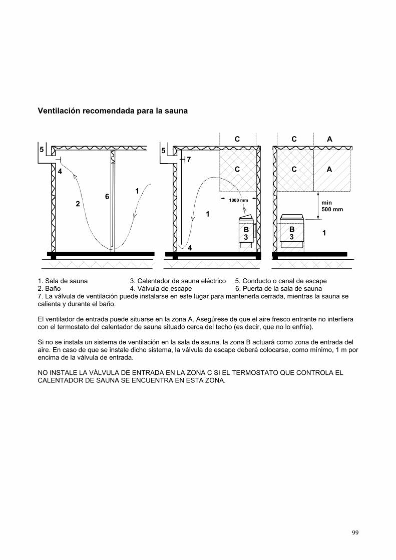
Ventilación recomendada para la sauna
1. Sala de sauna 3. Calentador de sauna eléctrico 5. Conducto o canal de escape 2. Baño 4. Válvula de escape 6. Puerta de la sala de sauna 7. La válvula de ventilación puede instalarse en este lugar para mantenerla cerrada, mientras la sauna se calienta y durante el baño. El ventilador de entrada puede situarse en la zona A. Asegúrese de que el aire fresco entrante no interfiera con el termostato del calentador de sauna situado cerca del techo (es decir, que no lo enfríe). Si no se instala un sistema de ventilación en la sala de sauna, la zona B actuará como zona de entrada del aire. En caso de que se instale dicho sistema, la válvula de escape deberá colocarse, como mínimo, 1 m por encima de la válvula de entrada. NO INSTALE LA VÁLVULA DE ENTRADA EN LA ZONA C SI EL TERMOSTATO QUE CONTROLA EL CALENTADOR DE SAUNA SE ENCUENTRA EN ESTA ZONA.
5 5
4
4
21
1
1
A7
A
min500 mm
6
3B
3B
C
C
C
C A
1000 mm
100
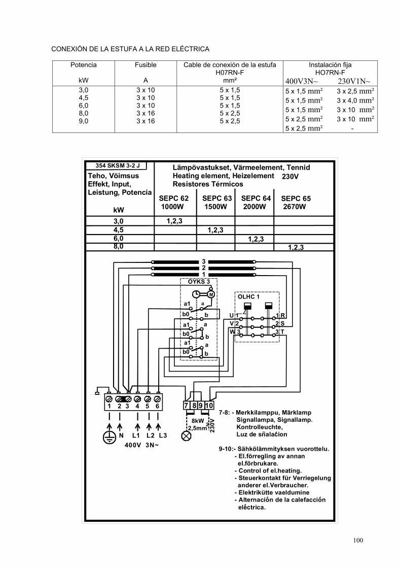
CONEXIÓN DE LA ESTUFA A LA RED ELÉCTRICA
Potencia
kW
Fusible
A
Cable de conexión de la estufa H07RN-F
mm²
Instalación fija HO7RN-F
400V3N~ 230V1N~ 3,0 4,5 6,0 8,0 9,0
3 x 10 3 x 10 3 x 10 3 x 16 3 x 16
5 x 1,5 5 x 1,5 5 x 1,5 5 x 2,5 5 x 2,5
5 x 1,5 mm² 3 x 2,5 mm²5 x 1,5 mm² 3 x 4,0 mm²5 x 1,5 mm² 3 x 10 mm²5 x 2,5 mm² 3 x 10 mm²5 x 2,5 mm² -
1 2 3 4 5 6
321
N L1 L2 L3 400V 3N~
a1
a1
a1
b0
b0
b0
a
ba
ab
b
4,56,08,0
1,2,31,2,3
1,2,3
OYKS 3
OLHC 1
U 1 1 RV 2 2 SW 3 3 T
8kW2,5mm2
230V
7 8 9 10
M
7-8: - Merkkilamppu, Märklamp Signallampa, Signallamp. Kontrolleuchte, Luz de snalacion
9-10:- Sähkölämmityksen vuorottelu. - El.förregling av annan el.förbrukare. - Control of el.heating. - Steuerkontakt für Verriegelung anderer el.Verbraucher. - Elektrikütte vaeldumine - Alternacion de la calefaccion electrica.
Teho, VöimsusEffekt, Input, Leistung, Potencia
kW
Lämpövastukset, Värmeelement, TennidHeating element, HeizelementResistores Termicos
230V354 SKSM 3-2 J
1,2,33,0
SEPC 64 2000W
SEPC 63 1500W
SEPC 62 1000W
SEPC 65 2670W
~

101
1 2 3 4 5 6
321
N L1 L2 L3 400V 3N~
Teho, EffektInput, Leistung,Vöimus, Potencia
kW
a1
a1
a1
b0
b0
b0
a
ba
ab
b
354 SKSM 3-3 C
19,0
SEPC 65C 3300W
SEPC 65B 3000W
SEPC 65 2670W
OYKS 3
OLHC 1
U 1 1 RV 2 2 SW 3 3 T
230V
7 8 9 10
M
2 3
2,5m
m2
2,5m
m27-8: - Merkkilamppu, Märklamp Signallampa, Signallamp. Kontrolleuchte, Luz de snalacion
9-10:- Sähkölämmityksen vuorottelu. - El.förregling av annan el.förbrukare. - Control of el.heating. - Steuerkontakt für Verriegelung anderer el.Verbraucher. - Elektrikütte vaeldumine - Alternacion de la calefaccion electrica.
~
Lämpövastukset, Värmeelement, TennidHeating element, HeizelementResistores Termicos
230V
123
Teho, EffektInput, LeistungVöimus, Potencia
kW
a1
a1
a1
b0
b0
b0
a
b
a
ab
b
M
354 SKSM 106 D
1,2,33,04,5 1,2,3
SEPC 63 1500W
SEPC 62 1000W
11
12
21
22
31
32
1 3 5 21 A1
2 4 6 22 A2
987 10
1 2 3 4 5 6
LN230V 1N~
1 2 3 4 5 6
L3N L1 L2400V 3N~
7-8: - Merkkilamppu, Märklamp Signallampa, Signallamp. Kontrolleuchte, Luz de snalacion
9-10:- Sähkölämmityksen vuorottelu. - El.förregling av annan el.förbrukare. - Control of el.heating. - Steuerkontakt für Verriegelung anderer el.Verbraucher. - Elektrikütte vaeldumine - Alternacion de la calefaccion electrica.
~
Lämpövastukset, Värmeelement, TennidHeating element, HeizelementResistores Termicos
230V

102
Teho, EffektInput, LeistungVöimsus kW
Lämpövastukset, Värmeelement, TennidHeating element, Heizeelement 230V-240V
SEPC 62 SEPC 63 SEPC 64 SEPC 65 1000W 1500W 2000W 2670W
1,2,3 1,2,3 1,2,3 1,2,3
3,04,56,08,0
123
a1
a1
a1
b0
b0
b0
a
b
a
ab
b
M 11
12
21
22
31
32
1 3 5 21 A1
2 4 6 22 A2
1 2 3 4 5 6
LN
230V-240V 1N~
1 2 3 4 5 6
L3N L1 L2
400V-415V 3N~354 SKSM 127 E
1712-30-1718, 1712-45-1718, 1712-60-1718, 1712-80-1718
Teho Jännite Sulake Kiukaan liitäntä johto Effekt Spänning Säkring Ugnens anslutnings kabel Input Voltage Fuse Cables to Heater Leistung Spannung Sicherung Kabel zum Ofen HO7RN-F
kW V A mm2
3 230 16 3 x 2,5 4,5 230 20 3 x 4,0 6 230 35 3 x 10 8 230 35 3 x 10 3 240 16 3 x 2,5 4,5 240 20 3 x 4,0 6 240 35 3 x 10 8 240 35 3 x 10