Instructions for Fitting, Operating and Maintenance Garage ... · 14 Warranty Conditions ..... 42...
49
TR10A108-E RE / 03.2017 EN Instructions for Fitting, Operating and Maintenance Garage Door Operator www.garagedoorsonline.co.uk 01926 463888
Transcript of Instructions for Fitting, Operating and Maintenance Garage ... · 14 Warranty Conditions ..... 42...
TR10
A10
8-E
RE
/ 03.
2017
EN Instructions for Fitting, Operating and Maintenance
Garage Door Operator
www.garagedoorsonline.co.uk 01926 463888
2 TR10A108-E RE / 03.2017
www.garagedoorsonline.co.uk 01926 463888
TR10A108-E RE / 03.2017 3
1 About These Instructions ....................................... 4
1.1 Further applicable documents .................................. 41.2 Warnings used .......................................................... 41.3 Definitions used ........................................................ 41.4 Symbols used ........................................................... 41.5 Abbreviations used ................................................... 5
2 Safety Instructions ........................................... 5
2.1 Intended use ............................................................. 52.2 Non-intended use ..................................................... 52.3 Fitter qualification ..................................................... 52.4 Safety instructions for fitting, maintenance,
repairs and disassembly of the door system ............ 52.5 Safety instructions for fitting ..................................... 62.6 Safety instructions for initial start-up and for
operation ................................................................... 62.7 Safety instructions for using the hand transmitter .... 62.8 Approved safety equipment...................................... 6
3 Fitting ....................................................................... 7
3.1 Inspect door/door system ........................................ 73.2 Clearance required.................................................... 73.3 Fitting the garage door operator ............................... 73.4 Fitting the boom ...................................................... 163.5 Determining the end-of-travel positions ................. 213.6 Emergency release.................................................. 233.7 Fixing the warning sign ........................................... 23
4 Electrical connection ............................................ 24
4.1 Connecting terminals .............................................. 244.2 Connecting additional components / accessories .... 24
5 Initial start-up ........................................................ 28
6 Menus .................................................................... 30
6.1 Menu description .................................................... 31
7 Teaching in the operator ...................................... 35
8 Hand transmitter HS 5 BiSecur ........................... 35
8.1 Description of the hand transmitter ........................ 368.2 Inserting / changing the battery ............................... 368.3 Hand transmitter operation ..................................... 368.4 Inheriting / transmitting a radio code ....................... 368.5 Querying the door position ..................................... 368.6 Hand transmitter reset ............................................ 378.7 LED display ............................................................. 378.8 Cleaning the hand transmitter ................................ 378.9 Disposal .................................................................. 378.10 Technical data ......................................................... 378.11 EU declaration of conformity for the
hand transmitter ...................................................... 37
Contents
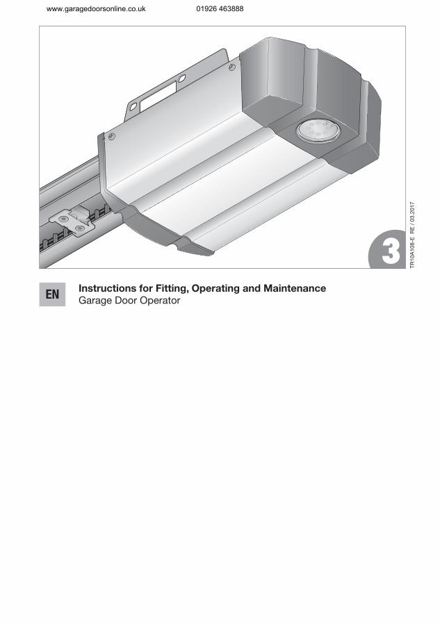
A Articles supplied ..................................................... 2
B Tools needed for fitting .......................................... 2
Dissemination as well as duplication of this document and the use and communication of its content are prohibited unless explicitly permitted. Non-compliance will result in damage compensation obligations. All rights reserved in the event of patent, utility model or design model registration. Subject to changes.
9 External radio receiver ......................................... 37
9.1 Teaching in hand transmitter buttons ..................... 379.2 EU Declaration of Conformity for Receivers ........... 38
10 Operation ............................................................... 38
10.1 Instructing users ..................................................... 3810.2 Function check ....................................................... 3910.3 Functions of various radio codes ........................... 3910.4 Garage door operator behaviour after two
consecutive high-speed Open runs ........................ 3910.5 Behaviour during a power failure
(without an emergency battery) .............................. 3910.6 Behaviour after the power returns
(without emergency battery) ................................... 3910.7 Reference run ......................................................... 39
11 Inspection and Maintenance ............................... 40
11.1 Tension of the toothed belt ..................................... 4011.2 Checking safety reversal / reversing ........................ 4011.3 Replacement bulb ................................................... 41
12 Factory reset ......................................................... 41
13 Dismantling and Disposal .................................... 42
14 Warranty Conditions ............................................. 42
15 EC / EU Declaration of Conformity /
Declaration of Incorporation ................................ 42
16 Technical Data ....................................................... 43
17 Display of Errors / Warnings and Operating
Conditions ............................................................. 44
17.1 Display of errors and warnings ............................... 4417.2 Display of Operating Conditions ............................. 45
18 Menu and programming overview ...................... 45
ENGLISH
www.garagedoorsonline.co.uk 01926 463888
4 TR10A108-E RE / 03.2017
Dear Customer, We are delighted that you have chosen a quality product from our company.
1 About These Instructions
These instructions are original operating instructions as outlined in the EC Directive 2006/42/EC. Read through all of the instructions carefully, as they contain important information about the product. Pay attention to and follow the instructions provided, particularly the safety instructions and warnings.Please keep these instructions in a safe place and make sure that they are available to all users at all times.
1.1 Further applicable documents
The following documents for safe handling and maintenance of the door system must be placed at the disposal of the end user:
These instructionsThe enclosed test manualThe garage door operating instructions
1.2 Warnings used
The general warning symbol indicates a danger that can lead to injury or death. In the text, the general warning symbol will be used in connection with the caution levels described below. In the illustrated section, an additional instruction refers back to the explanation in the text section.
DANGER
Indicates a danger that can immediately lead to death or serious injuries.
WARNING
Indicates a danger that can lead to death or serious injuries.
CAUTION
Indicates a danger that can lead to minor or moderate injuries.
ATTENTION
Indicates a danger that can lead to damage or destruction
of the product.
1.3 Definitions used
Automatic timer
Automatic closing of the door after a set time has elapsed and after reaching the Open end-of-travel position or partial opening.
Impulse sequence control
With each push of the button, the door is started against the previous direction of travel or the motion of the door is stopped.
Learning runs
Door runs in which the travel and the forces needed for moving the door are taught in.
Normal operation
Door travel with the taught-in travel distances and forces.
Safety reversal / reversing
Door travel in the opposite direction when the safety device or power limit is activated.
Reversal limit
If a safety device is activated, the door moves into the opposite direction (safety reversal) up to the reversal limit shortly before the Close end-of-travel position. If this limit is passed, no reversal occurs to ensure that the door reaches the end-of-travel position in one go.
Partial opening
Individually adjustable second opening height to ventilate the garage.
Timeout
A defined period in which an action is expected to take place (e.g. using the menu or activating a function). The operator automatically goes into operation mode if this period elapses without an action taking place.
Travel
The distance the door takes to move from the Open end-of-travel position to the Close end-of-travel position.
Pre-warning time
The time between the travel command (impulse) and the actual start of travel.
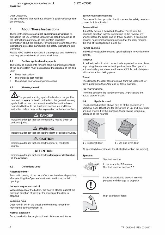
1.4 Symbols used
The illustrated section shows how to fit the operator on a sectional door. Deviations for fitting with an up-and-over door are also shown. For this purpose, the following letters are assigned to the figures:
a = Sectional door b = Up-and-over door
All specified dimensions in the illustrated section are in [mm].
Symbols:
2.2
See text section
In the example, 2.2 means: See text section, section 2.2
Important advice to prevent injury to persons and damage to property
High exertion of force
ENGLISH
www.garagedoorsonline.co.uk 01926 463888
TR10A108-E RE / 03.2017 5
Check for smooth running
Use protective gloves
Factory setting
7-segment display
Display illuminated
Display flashes slowly.
Display flashes rapidly.
Dot flashes
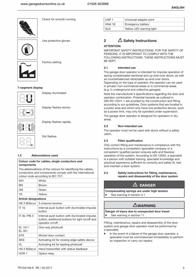
1.5 Abbreviations used
Colour code for cables, single conductors and
components
The abbreviations of the colours for identifying the cables, conductors and components comply with the international colour code according to IEC 757:WH WhiteBN BrownGN GreenYE YellowArticle designations
HE 3 BiSecur 3-channel receiverIT 1b Internal push button with illuminated impulse
buttonIT 3b / PB 3 Internal push button with illuminated impulse
button, additional buttons for light on/off and operator on/off
EL 101 /EL 301
One-way photocell
STK Wicket door contactSKS Activating kit for closing edge safety deviceVL Activating kit for leading photocellHS 5 BiSecur Hand transmitter with status feedbackHOR 1 Option relay
UAP 1 Universal adapter printHNA 18 Emergency batterySLK Yellow LED warning light
2 Safety Instructions
ATTENTION:
IMPORTANT SAFETY INSTRUCTIONS. FOR THE SAFETY OF PERSONS, IT IS IMPORTANT TO COMPLY WITH THE FOLLOWING INSTRUCTIONS. THESE INSTRUCTIONS MUST BE KEPT.
2.1 Intended use
The garage door operator is intended for impulse operation of spring compensated sectional and up-and-over doors, as well as counterbalanced retractable up-and-over doors. Depending on the type of operator, the operator can be used in private / non-commercial areas or in commercial areas (e.g. in underground and collective garages).Note the manufacturer's specifications regarding the door and operator combination. Potential hazards as outlined in DIN EN 13241-1 are avoided by the construction and fitting according to our guidelines. Door systems that are located in a public area and which only have one protective device, such as a power limit, may only be operated under supervision.The garage door operator is designed for operation in dry areas.
2.2 Non-intended use
The operator must not be used with doors without a safety catch.
2.3 Fitter qualification
Only correct fitting and maintenance in compliance with the instructions by a competent / specialist company or a competent / qualified person ensures safe and flawless operation of the system. According to EN 12635, a specialist is a person with suitable training, specialist knowledge and practical experience sufficient to correctly and safely fit, test and maintain a door system.
2.4 Safety instructions for fitting, maintenance,
repairs and disassembly of the door system
DANGER
Compensating springs are under high tension
▶ See warning in section 3.1
WARNING
Danger of injury due to unexpected door travel
▶ See warning in section 11
Fitting, maintenance, repairs and disassembly of the door system and garage door operator must be performed by a specialist.▶ In the event of a failure of the garage door operator, a
specialist must be commissioned immediately to perform an inspection or carry out repairs.
ENGLISH
www.garagedoorsonline.co.uk 01926 463888
6 TR10A108-E RE / 03.2017
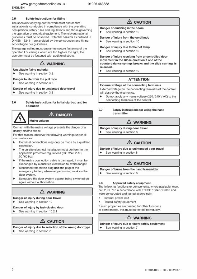
2.5 Safety instructions for fitting
The specialist carrying out the work must ensure that installation is conducted in compliance with the prevailing occupational safety rules and regulations and those governing the operation of electrical equipment. The relevant national guidelines must be observed. Potential hazards as outlined in DIN EN 13241-1 are avoided by the construction and fitting according to our guidelines.The garage ceiling must guarantee secure fastening of the operator. For ceilings which are too high or too light, the operator must be fastened with additional struts.
WARNING
Unsuitable fixing material
▶ See warning in section 3.3
Danger to life from the pull rope
▶ See warning in section 3.3
Danger of injury due to unwanted door travel
▶ See warning in section 3.3
2.6 Safety instructions for initial start-up and for
operation
DANGER
Mains voltage
Contact with the mains voltage presents the danger of a deadly electric shock.For that reason, observe the following warnings under all circumstances:▶ Electrical connections may only be made by a qualified
electrician.▶ The on-site electrical installation must conform to the
applicable protective regulations (230 / 240 V AC, 50 / 60 Hz)!
▶ If the mains connection cable is damaged, it must be exchanged by a qualified electrician to avoid danger.
▶ Disconnect the mains plug and the plug of the emergency battery whenever performing work on the door system.
▶ Safeguard the door system against being switched on again without authorisation.
WARNING
Danger of injury during door travel
▶ See warning in section 10
Danger of injury by fast-closing door
▶ See warning in section 10.2.1
CAUTION
Danger of injury due to selection of the wrong door type
▶ See warning in section 7
CAUTION
Danger of crushing in the boom
▶ See warning in section 10
Danger of injury from the cord knob
▶ See warning in section 10
Danger of injury due to the hot lamp
▶ See warning in section 10
Danger of injury resulting from uncontrolled door
movement in the Close direction if one of the
counterbalance springs breaks and the slide carriage is
released.
▶ See warning in section 10
ATTENTION
External voltage at the connecting terminals
External voltage on the connecting terminals of the control will destroy the electronics.▶ Do not apply any mains voltage (230 / 240 V AC) to the
connecting terminals of the control.
2.7 Safety instructions for using the hand
transmitter
WARNING
Danger of injury during door travel
▶ See warning in section 8
CAUTION
Danger of injury due to unintended door travel
▶ See warning in section 8
CAUTION
Danger of burns from the hand transmitter
▶ See warning in section 8
2.8 Approved safety equipment
The following functions or components, where available, meet cat. 2, PL “c” in accordance with EN ISO 13849-1:2008 and were constructed and tested accordingly:
Internal power limit Tested safety equipment
If such properties are needed for other functions or components, this must be tested individually.
WARNING
Danger of injury due to faulty safety equipment
▶ See warning in section 7
ENGLISH
www.garagedoorsonline.co.uk 01926 463888
TR10A108-E RE / 03.2017 7
3 Fitting
ATTENTION:
IMPORTANT INSTRUCTIONS FOR SAFE FITTING. OBSERVE ALL INSTRUCTIONS, INCORRECT FITTING COULD RESULT IN SERIOUS INJURIES.
3.1 Inspect door/door system
DANGER
Compensating springs are under high tension
Serious injuries may occur while adjusting or loosening the compensating springs!▶ For your own safety, only have a specialist conduct
work on the door compensating springs. The same applies to all maintenance and repair work!
▶ Never try to replace, adjust, repair or reposition the compensating springs for the counterbalance of the door or the spring mountings yourself.
▶ In addition, check the entire door system (joints, door bearings, cables, springs and fastenings) for wear and possible damage.
▶ Check for the presence of rust, corrosion and cracks.A malfunction in the door system or an incorrectly aligned door can cause serious injuries!▶ Do not use the door system if repair or adjustment work
must be conducted!
The construction of the operator is not designed for operation with sluggish doors, i.e. doors that can hardly or not at all be opened or closed manually.The door must be in a flawless mechanical condition, as well as correctly balanced, so that it can be easily operated by hand (EN 12604).▶ Lift the door by approx. one metre and let it go. The door
should stay in this position and neither move downward nor upward. If the door does move in either direction, there is a danger that the compensating springs / weights are not properly adjusted or are defective. In this case, increased wear and malfunctioning of the door system can be expected.
▶ Check whether the door can be opened and closed correctly.
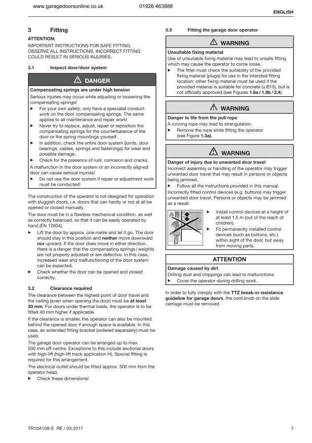
3.2 Clearance required
The clearance between the highest point of door travel and the ceiling (even when opening the door) must be at least
30 mm. For doors under thermal loads, the operator is to be fitted 40 mm higher if applicable.If the clearance is smaller, the operator can also be mounted behind the opened door if enough space is available. In this case, an extended fitting bracket (ordered separately) must be used.The garage door operator can be arranged up to max. 500 mm off-centre. Exceptions to this include sectional doors with high-lift (high-lift track application H). Special fitting is required for this arrangement.The electrical outlet should be fitted approx. 500 mm from the operator head.▶ Check these dimensions!
3.3 Fitting the garage door operator
WARNING
Unsuitable fixing material
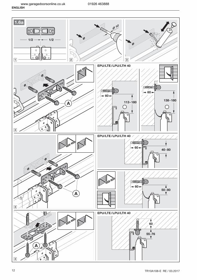
Use of unsuitable fixing material may lead to unsafe fitting which may cause the operator to come loose.▶ The fitter must check the suitability of the provided
fixing material (plugs) for use in the intended fitting location; other fixing material must be used if the provided material is suitable for concrete (≥ B15), but is not officially approved (see Figures 1.6a / 1.8b / 2.4).
WARNING
Danger to life from the pull rope
A running rope may lead to strangulation.▶ Remove the rope while fitting the operator
(see Figure 1.3a).
WARNING
Danger of injury due to unwanted door travel
Incorrect assembly or handling of the operator may trigger unwanted door travel that may result in persons or objects being jammed.▶ Follow all the instructions provided in this manual.Incorrectly fitted control devices (e.g. buttons) may trigger unwanted door travel. Persons or objects may be jammed as a result.
▶ Install control devices at a height of at least 1.5 m (out of the reach of children).
▶ Fit permanently installed control devices (such as buttons, etc.) within sight of the door, but away from moving parts.
ATTENTION
Damage caused by dirt
Drilling dust and chippings can lead to malfunctions.▶ Cover the operator during drilling work.
In order to fully comply with the TTZ break-in resistance
guideline for garage doors, the cord knob on the slide carriage must be removed.
ENGLISH
www.garagedoorsonline.co.uk 01926 463888
8 TR10A108-E RE / 03.2017
ENGLISH
www.garagedoorsonline.co.uk 01926 463888
TR10A108-E RE / 03.2017 9
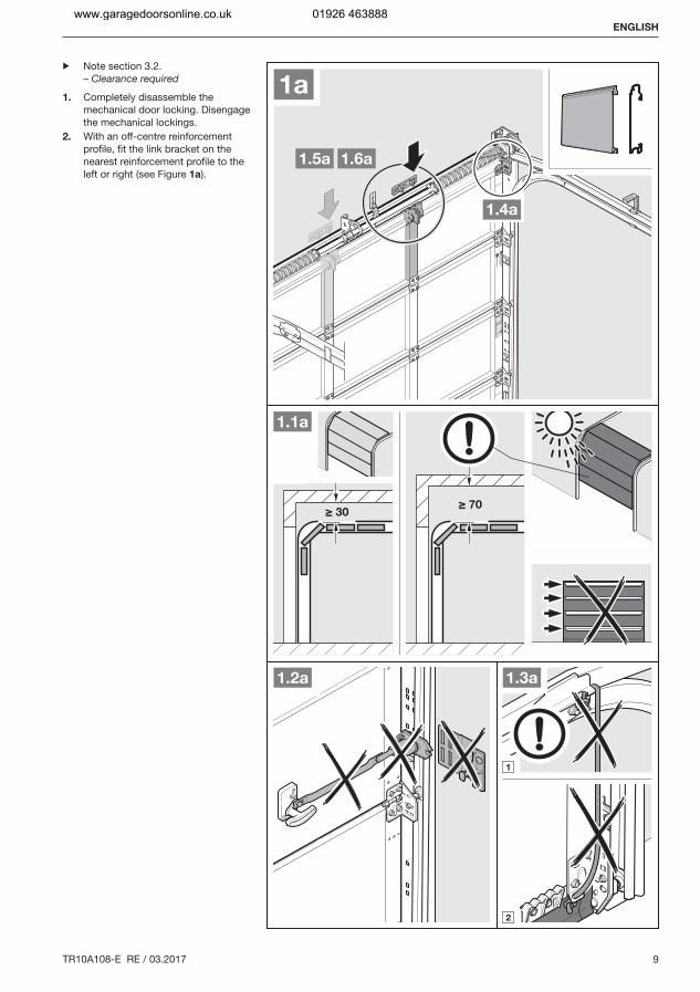
≥ 30≥ 70
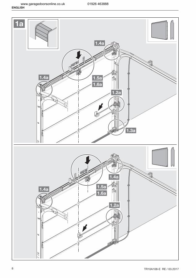
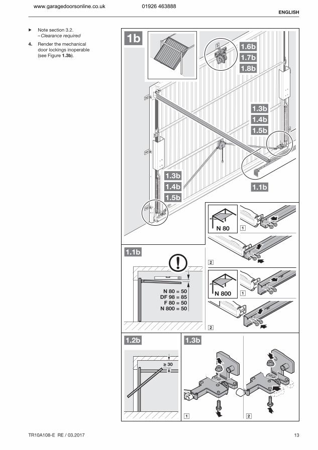
▶ Note section 3.2. – Clearance required
1. Completely disassemble the mechanical door locking. Disengage the mechanical lockings.
2. With an off-centre reinforcement profile, fit the link bracket on the nearest reinforcement profile to the left or right (see Figure 1a).
ENGLISH
www.garagedoorsonline.co.uk 01926 463888
10 TR10A108-E RE / 03.2017
ENGLISH
www.garagedoorsonline.co.uk 01926 463888
TR10A108-E RE / 03.2017 11
1/2 1/2
1.5a
Ø 5
B
B B
B
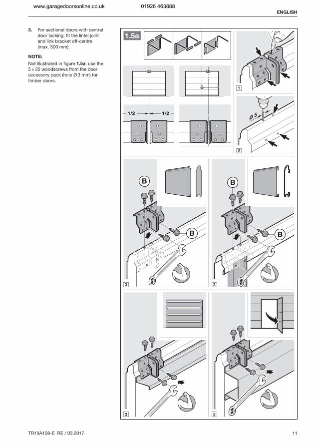
3. For sectional doors with central door locking, fit the lintel joint and link bracket off-centre (max. 500 mm).
NOTE:
Not illustrated in figure 1.5a: use the 5 × 35 woodscrews from the door accessory pack (hole Ø 3 mm) for timber doors.
ENGLISH
www.garagedoorsonline.co.uk 01926 463888
12 TR10A108-E RE / 03.2017
1/2 1/2
A 113-180
60
Ø 10
EPU/LTE/LPU/LTH 40
138-180
60
1.6a
A
55-76
60
EPU/LTE/LPU/LTH 40
6050-80
A
40-8060
EPU/LTE/LPU/LTH 40
ENGLISH
www.garagedoorsonline.co.uk 01926 463888
TR10A108-E RE / 03.2017 13
▶ Note section 3.2. – Clearance required
4. Render the mechanical door lockings inoperable (see Figure 1.3b).
ENGLISH
www.garagedoorsonline.co.uk 01926 463888
14 TR10A108-E RE / 03.2017
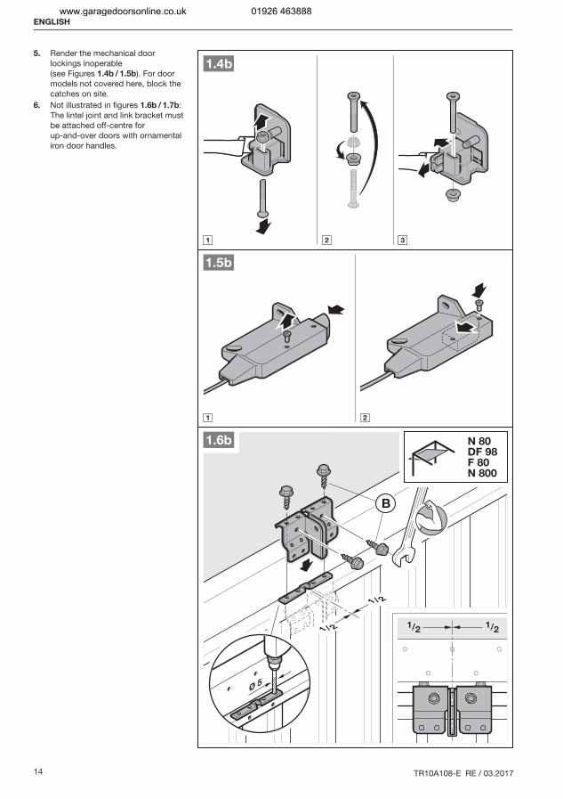
5. Render the mechanical door lockings inoperable (see Figures 1.4b / 1.5b). For door models not covered here, block the catches on site.
6. Not illustrated in figures 1.6b / 1.7b: The lintel joint and link bracket must be attached off-centre for up-and-over doors with ornamental iron door handles.
ENGLISH
www.garagedoorsonline.co.uk 01926 463888
TR10A108-E RE / 03.2017 15
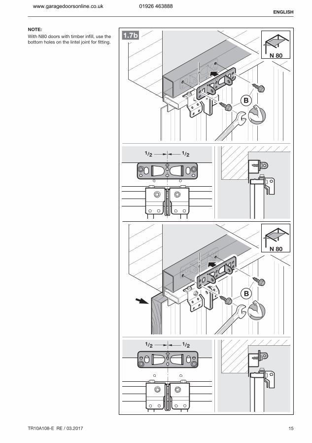
NOTE:
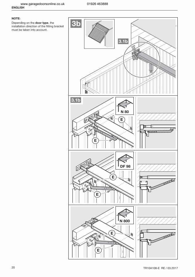
With N80 doors with timber infill, use the bottom holes on the lintel joint for fitting.
ENGLISH
www.garagedoorsonline.co.uk 01926 463888
16 TR10A108-E RE / 03.2017
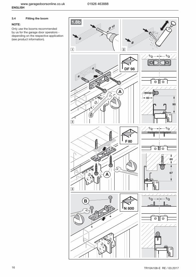
3.4 Fitting the boom
NOTE:
Only use the booms recommended by us for the garage door operators - depending on the respective application (see product information).
ENGLISH
www.garagedoorsonline.co.uk 01926 463888
TR10A108-E RE / 03.2017 17
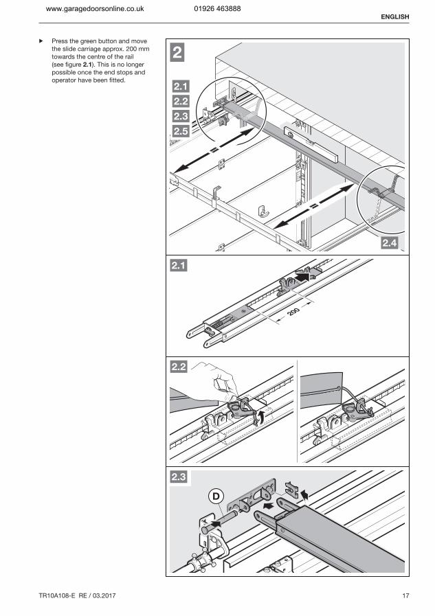
▶ Press the green button and move the slide carriage approx. 200 mm towards the centre of the rail (see figure 2.1). This is no longer possible once the end stops and operator have been fitted.
ENGLISH
www.garagedoorsonline.co.uk 01926 463888
18 TR10A108-E RE / 03.2017
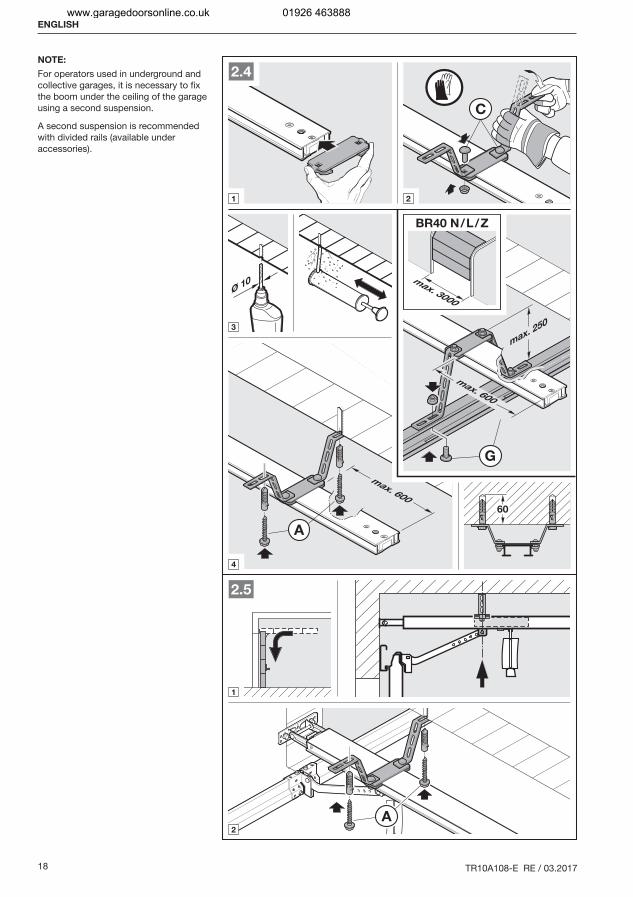
NOTE:
For operators used in underground and collective garages, it is necessary to fix the boom under the ceiling of the garage using a second suspension.
A second suspension is recommended with divided rails (available under accessories).
ENGLISH
www.garagedoorsonline.co.uk 01926 463888
TR10A108-E RE / 03.2017 19
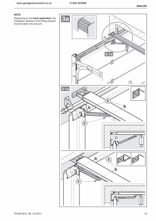
NOTE:
Depending on the track application, the installation direction of the fitting bracket must be taken into account.
ENGLISH
www.garagedoorsonline.co.uk 01926 463888
20 TR10A108-E RE / 03.2017
NOTE:
Depending on the door type, the installation direction of the fitting bracket must be taken into account.
ENGLISH
www.garagedoorsonline.co.uk 01926 463888
TR10A108-E RE / 03.2017 21
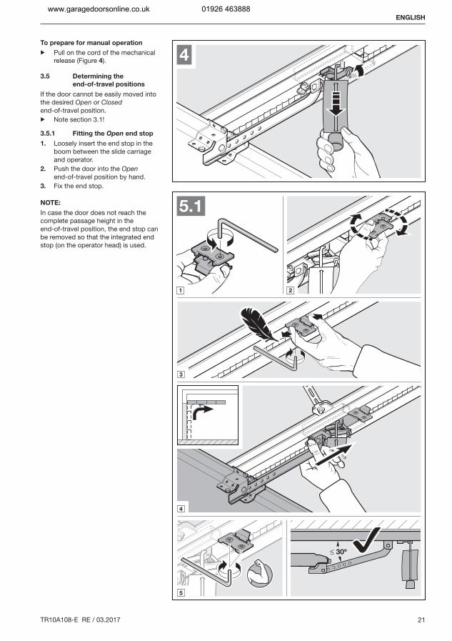
To prepare for manual operation
▶ Pull on the cord of the mechanical release (Figure 4).
3.5 Determining the
end-of-travel positions
If the door cannot be easily moved into the desired Open or Closed end-of-travel position.▶ Note section 3.1!
3.5.1 Fitting the Open end stop
1. Loosely insert the end stop in the boom between the slide carriage and operator.
2. Push the door into the Open end-of-travel position by hand.
3. Fix the end stop.
NOTE:
In case the door does not reach the complete passage height in the end-of-travel position, the end stop can be removed so that the integrated end stop (on the operator head) is used.
ENGLISH
www.garagedoorsonline.co.uk 01926 463888
22 TR10A108-E RE / 03.2017
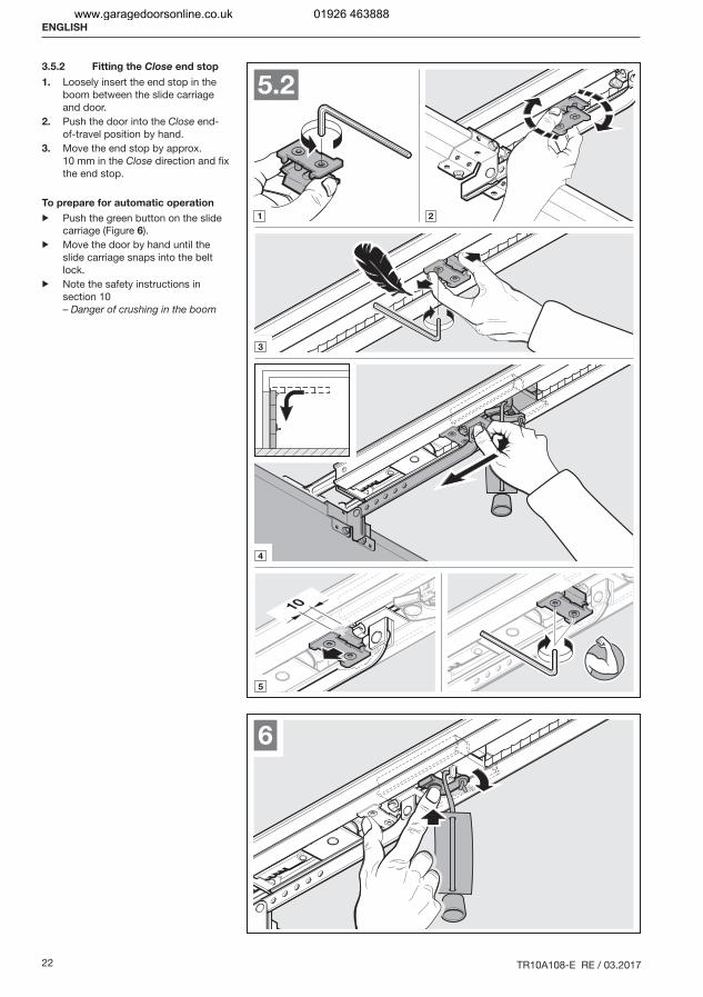
3.5.2 Fitting the Close end stop
1. Loosely insert the end stop in the boom between the slide carriage and door.
2. Push the door into the Close end-of-travel position by hand.
3. Move the end stop by approx. 10 mm in the Close direction and fix the end stop.
To prepare for automatic operation
▶ Push the green button on the slide carriage (Figure 6).
▶ Move the door by hand until the slide carriage snaps into the belt lock.
▶ Note the safety instructions in section 10 – Danger of crushing in the boom
ENGLISH
www.garagedoorsonline.co.uk 01926 463888
TR10A108-E RE / 03.2017 23
F
≥ 100
7
min.1500
8a
9
8b
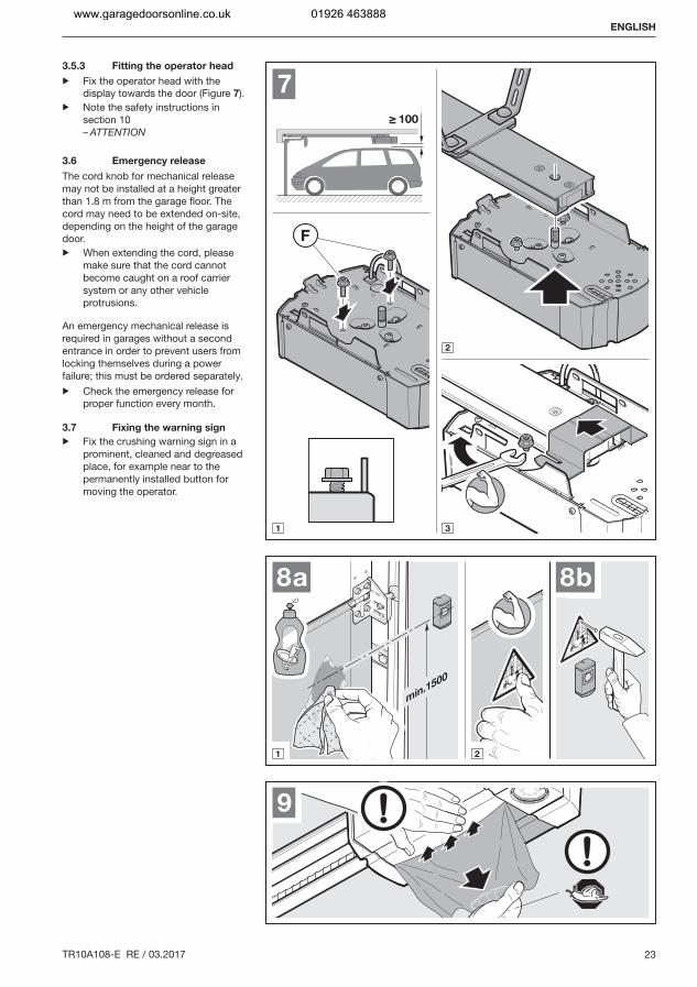
3.5.3 Fitting the operator head
▶ Fix the operator head with the display towards the door (Figure 7).
▶ Note the safety instructions in section 10 – ATTENTION
3.6 Emergency release
The cord knob for mechanical release may not be installed at a height greater than 1.8 m from the garage floor. The cord may need to be extended on-site, depending on the height of the garage door.▶ When extending the cord, please
make sure that the cord cannot become caught on a roof carrier system or any other vehicle protrusions.
An emergency mechanical release is required in garages without a second entrance in order to prevent users from locking themselves during a power failure; this must be ordered separately.▶ Check the emergency release for
proper function every month.
3.7 Fixing the warning sign
▶ Fix the crushing warning sign in a prominent, cleaned and degreased place, for example near to the permanently installed button for moving the operator.
ENGLISH
www.garagedoorsonline.co.uk 01926 463888
24 TR10A108-E RE / 03.2017
+ -+ -
23
5
21
12
min. 1 x 0,5 mm2
max. 1 x 2,5 mm2
IT 1b
230-240 VX30
23
5
21
20 BUS
I2
24V
I1
0V
YE
BN
WH
GN
11
10
HE 3 BiSecur10 mA
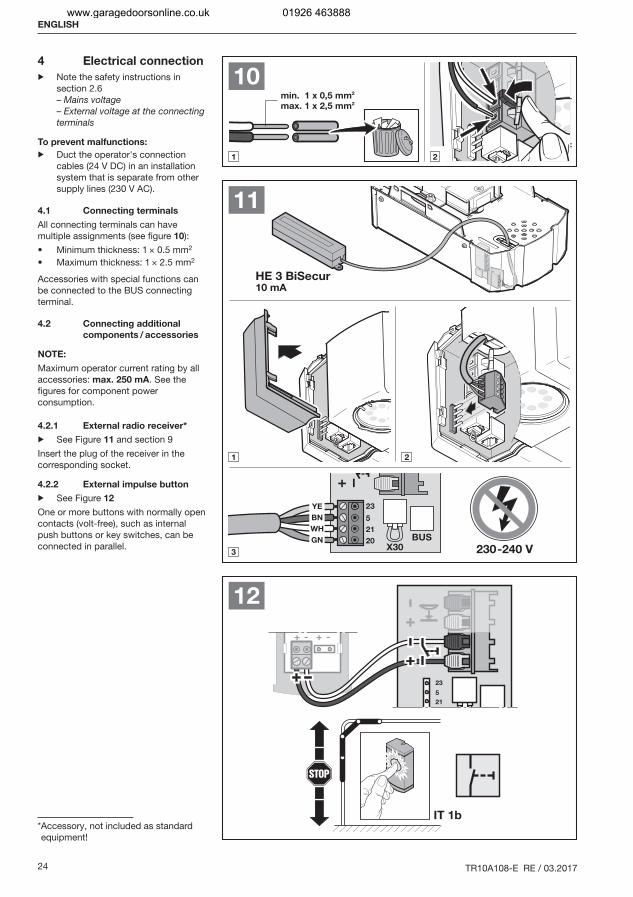
4 Electrical connection
▶ Note the safety instructions in section 2.6 – Mains voltage – External voltage at the connecting terminals
To prevent malfunctions:
▶ Duct the operator's connection cables (24 V DC) in an installation system that is separate from other supply lines (230 V AC).
4.1 Connecting terminals
All connecting terminals can have multiple assignments (see figure 10):
Minimum thickness: 1 × 0.5 mm2
Maximum thickness: 1 × 2.5 mm2
Accessories with special functions can be connected to the BUS connecting terminal.
4.2 Connecting additional
components / accessories
NOTE:
Maximum operator current rating by all accessories: max. 250 mA. See the figures for component power consumption.
4.2.1 External radio receiver*
▶ See Figure 11 and section 9Insert the plug of the receiver in the corresponding socket.
4.2.2 External impulse button
▶ See Figure 12
One or more buttons with normally open contacts (volt-free), such as internal push buttons or key switches, can be connected in parallel.
* Accessory, not included as standard equipment!
ENGLISH
www.garagedoorsonline.co.uk 01926 463888
TR10A108-E RE / 03.2017 25
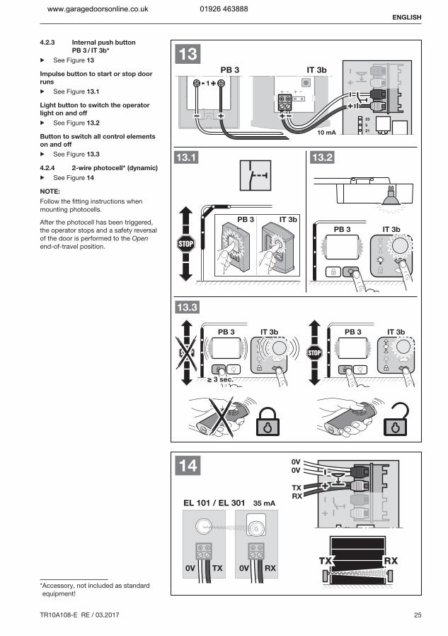
4.2.3 Internal push button
PB 3 / IT 3b*
▶ See Figure 13
Impulse button to start or stop door
runs
▶ See Figure 13.1
Light button to switch the operator
light on and off
▶ See Figure 13.2
Button to switch all control elements
on and off
▶ See Figure 13.3
4.2.4 2-wire photocell* (dynamic)
▶ See Figure 14
NOTE:
Follow the fitting instructions when mounting photocells.
After the photocell has been triggered, the operator stops and a safety reversal of the door is performed to the Open end-of-travel position.
* Accessory, not included as standard equipment!
ENGLISH
www.garagedoorsonline.co.uk 01926 463888
26 TR10A108-E RE / 03.2017
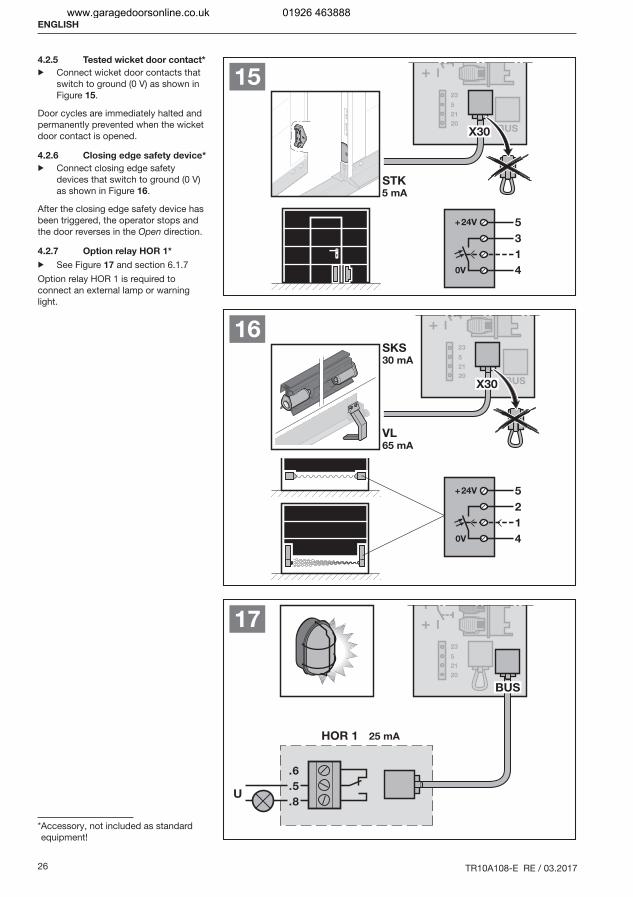
4.2.5 Tested wicket door contact*
▶ Connect wicket door contacts that switch to ground (0 V) as shown in Figure 15.
Door cycles are immediately halted and permanently prevented when the wicket door contact is opened.
4.2.6 Closing edge safety device*
▶ Connect closing edge safety devices that switch to ground (0 V) as shown in Figure 16.
After the closing edge safety device has been triggered, the operator stops and the door reverses in the Open direction.
4.2.7 Option relay HOR 1*
▶ See Figure 17 and section 6.1.7Option relay HOR 1 is required to connect an external lamp or warning light.
* Accessory, not included as standard equipment!
ENGLISH
www.garagedoorsonline.co.uk 01926 463888
TR10A108-E RE / 03.2017 27
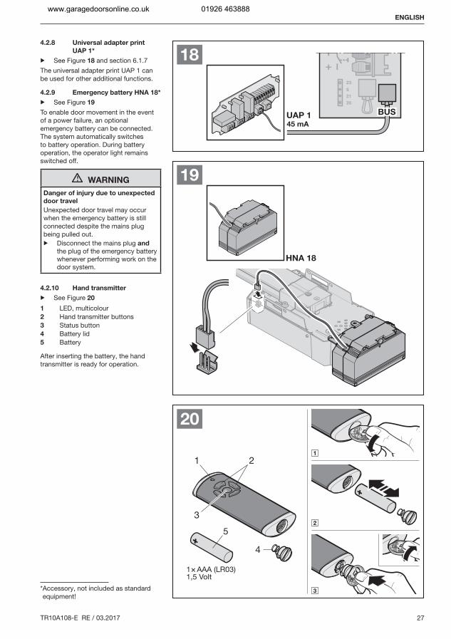
4.2.8 Universal adapter print
UAP 1*
▶ See Figure 18 and section 6.1.7The universal adapter print UAP 1 can be used for other additional functions.
4.2.9 Emergency battery HNA 18*
▶ See Figure 19
To enable door movement in the event of a power failure, an optional emergency battery can be connected. The system automatically switches to battery operation. During battery operation, the operator light remains switched off.
WARNING
Danger of injury due to unexpected
door travel
Unexpected door travel may occur when the emergency battery is still connected despite the mains plug being pulled out.▶ Disconnect the mains plug and
the plug of the emergency battery whenever performing work on the door system.
4.2.10 Hand transmitter
▶ See Figure 20
1 LED, multicolour2 Hand transmitter buttons3 Status button4 Battery lid5 Battery
After inserting the battery, the hand transmitter is ready for operation.
* Accessory, not included as standard equipment!
ENGLISH
www.garagedoorsonline.co.uk 01926 463888
28 TR10A108-E RE / 03.2017
5 Initial start-up
▶ Before initial start-up, read and follow the safety instructions in sections 2.6 and 2.8.
NOTES:
The hand transmitter must be ready for operation (see section 4.2.10)The slide carriage must be engaged and there may not be any obstacles in the function range of the safety devices!Safety devices must be fitted and connected beforehand.If further safety devices are connected at a later point, a new learning run is required (menu 10).When teaching in, the connected safety devices and power limit are not active.
▶ See Figure 21
1. Plug in the mains plug.A U is illuminated in the display.
2. Select the existing door type.An L will then be illuminated in the display.
Door types:
Menu Door type
01 = Sectional door02 = Up-and-over door 1)
03 = Side sliding sectional door04 = Non-protruding up-and-over door 2) (e.g. ET 500) 3)
05 = Sliding door 4) (e.g. ST 500) 3)
1) A door swinging outwards2) A door tilting inwards3) Dependent on the operator type4) With this door type, an 8k2 resistance contact strip must be fitted to
the secondary closing edge in the Open direction and connected to the operator via the 8k2-1T decoder unit.
NOTE:
▶ Set menu 03 for hinged doors.
Timeout
If the timeout (60 seconds) elapses before starting the learning run, the operator will automatically switch back to the delivery condition.
3. Press the button .– The door will open and briefly stop in the Open
end-of-travel position.– The door will automatically go through 3 complete
cycles (Open and Close). In the process the travel, required forces, and connected safety devices will be taught in.
The operator light and L in the display flash during the learning run.– The door will stop in the Open end-of-travel position.
The operator light remains illuminated and goes out after 60 seconds.
To abort a learning run:
▶ Press one of the buttons or , the PRG button or an external control element with impulse function.A U in the display shows that the operator has not been taught in.
Display of the taught-in forces
A number will be illuminated after the learning runs. This indicates the maximum detected force.
The numbers represent the following:0-2 Optimum force conditions
The door system is moving easily.3-9 Poor force conditions
The door system must be inspected or readjusted.
Once the taught-in forces have been displayed, the operator will automatically switch to the menu to register the hand transmitters for the impulse control function. An 11 will flash in the display.
To register a hand transmitter (impulse):
4. Press the hand transmitter button whose radio code you want to transmit and keep it pressed. (Please see section 8.4 for more information on the hand transmitter). If a valid radio code is detected, the 11 flashes quickly in the display.
5. Release the hand transmitter button.The hand transmitter has been registered and is ready
for operation.
The 11 flashes in the display and you can register further hand transmitters.
If you want to cancel hand transmitter registration or not
register any further hand transmitters:
▶ Press the PRG button.
Press the buttons or to select menu 00 (exit programming mode) or wait for the timeout to elapse to switch to operation mode. or
5.1 Press the buttons or , to select menu 12 (operator light) or menu 13 (partial opening).
6. Press the PRG button to change to programming mode.7. In menus 12 and 13, proceed exactly as described in
steps 4 + 5.
The operator is ready for operation.
Timeout
If the timeout elapses (25 seconds) while registering the hand transmitter, the operator will automatically switch to operation mode. To register a hand transmitter, the corresponding menu must then be selected manually (see section 6.1.3).
ENGLISH
www.garagedoorsonline.co.uk 01926 463888

TR10A108-E RE / 03.2017 29
ENGLISH
www.garagedoorsonline.co.uk 01926 463888
30 TR10A108-E RE / 03.2017
6 Menus
NOTES:
With the function blocks that consist of several menus, only one menu may be selected per block.After the operator has been taught in, only the selectable menus 10 – 46 are shown. Menus 01 – 05 are only accessible during initial start-up. Menu 00 is used to exit programming mode.A decimal point next to the menu number indicates an active menu.
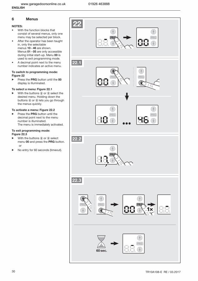
To switch to programming mode:
Figure 22
▶ Press the PRG button until the 00 display is illuminated.
To select a menu: Figure 22.1
▶ With the buttons or select the desired menu. Holding down the buttons or lets you go through the menus quickly.
To activate a menu: Figure 22.2
▶ Press the PRG button until the decimal point next to the menu number is illuminated.The menu is immediately activated.
To exit programming mode:
Figure 22.3
▶ With the buttons or select menu 00 and press the PRG button.or
▶ No entry for 60 seconds (timeout).
ENGLISH
www.garagedoorsonline.co.uk 01926 463888
TR10A108-E RE / 03.2017 31
6.1 Menu description
A table containing all of the menus can be found in section 18, from page 45.If you switch to programming mode, the operator light will be illuminated for 60 seconds. Pressing the buttons , or PRG extends the time the light is on.
6.1.1 Menu 01 – 05: Door types
Menus 01 – 05 are needed for initial start-up of the operator. They are only accessible during initial start-up or after a factory reset.Once the door type has been selected, all of the door-specific values, such as speed, soft stop, reversing behaviour of the safety devices, reversal limits, etc. will be pre-set automatically.▶ For an overview of door types, see section 5
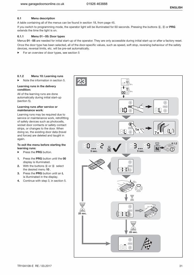
6.1.2 Menu 10: Learning runs
▶ Note the information in section 5.
Learning runs in the delivery
condition:
All of the learning runs are done automatically during initial start-up (section 5).
Learning runs after service or
maintenance work:
Learning runs may be required due to service or maintenance work, retrofitting of safety devices such as photocells, wicket door contacts or safety contact strips, or changes to the door. When doing so, the existing door data (travel and forces) are deleted and taught in again.
To exit the menu before starting the
learning runs:
▶ Press the PRG button.
1. Press the PRG button until the 00 display is illuminated.
2. With the buttons or select the desired menu 10 .
3. Press the PRG button until an L is illuminated in the display.
4. Continue with step 3, in section 5.
ENGLISH
www.garagedoorsonline.co.uk 01926 463888
32 TR10A108-E RE / 03.2017
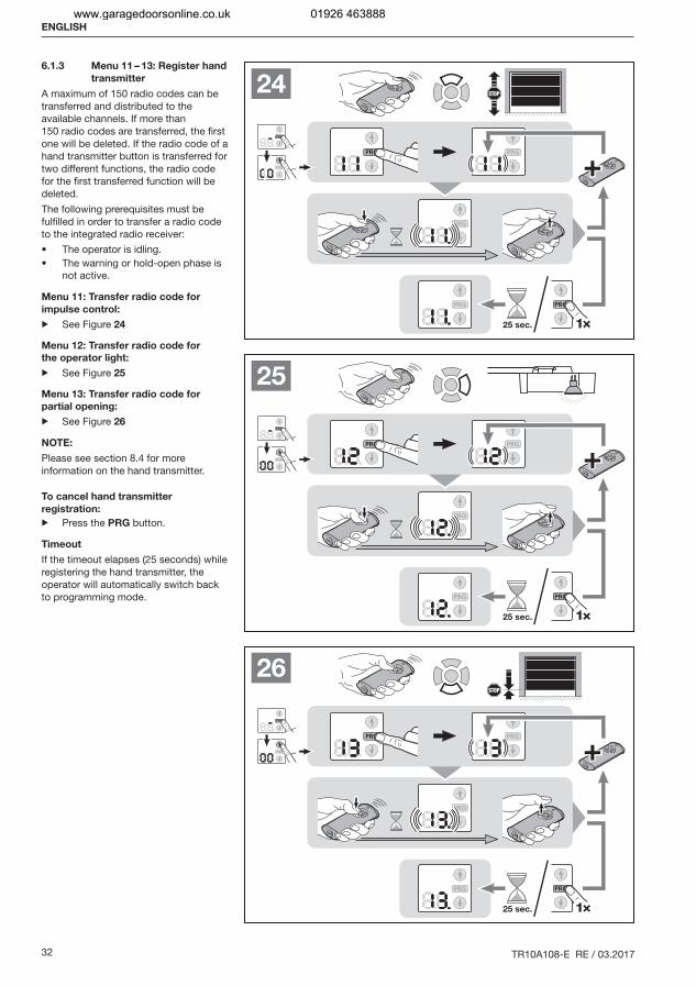
6.1.3 Menu 11 – 13: Register hand
transmitter
A maximum of 150 radio codes can be transferred and distributed to the available channels. If more than 150 radio codes are transferred, the first one will be deleted. If the radio code of a hand transmitter button is transferred for two different functions, the radio code for the first transferred function will be deleted.The following prerequisites must be fulfilled in order to transfer a radio code to the integrated radio receiver:
The operator is idling.The warning or hold-open phase is not active.
Menu 11: Transfer radio code for
impulse control:
▶ See Figure 24
Menu 12: Transfer radio code for
the operator light:
▶ See Figure 25
Menu 13: Transfer radio code for
partial opening:
▶ See Figure 26
NOTE:
Please see section 8.4 for more information on the hand transmitter.
To cancel hand transmitter
registration:
▶ Press the PRG button.
Timeout
If the timeout elapses (25 seconds) while registering the hand transmitter, the operator will automatically switch back to programming mode.
ENGLISH
www.garagedoorsonline.co.uk 01926 463888
TR10A108-E RE / 03.2017 33
About the menus described here:
▶ See also the overview from page 45.
6.1.4 Menu 14: Query door type
During initial start-up or after a factory reset, you can query the set door type via menu 14.
To query the door type:
1. Select menu 14 as described in section 6.2. Press the PRG button.
The set door type will be displayed as long as the PRG button is pressed.
6.1.5 Menu 15 – 18: Operator light controlled by the
operator
The operator light is switched on as soon as the door starts moving. After the door has stopped moving, the operator light remains on for the set period (illumination period).If menu 15 is activated, the operator light will not be switched on once the door starts moving.The illumination period for the operator light can be set using menus 16 – 18.
To set the desired function:
▶ Select the menu for the desired function as described in section 6.
6.1.6 Menu 19 – 21: Operator light controlled by
external control elements
The operator light can be switched on with an external control element (e.g. hand transmitter or internal push button IT 3b, PB 3) and remains on for the set period (illumination period).If menu 19 is activated, the operator light cannot be switched on with an external control element.The illumination period for the operator light can be set using menus 20 – 21. Menu 23 is also activated automatically.
To set the desired function:
▶ Select the menu for the desired function as described in section 6.
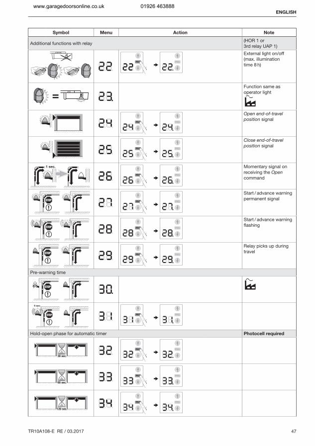
6.1.7 Menu 22 – 29: Functions with additional print
If menu 22 is activated, the external light can be turned on and off permanently. Not possible in combination with menu 23. The operator light is always deactivated.If menu 22 is activated, menu 19 is also automatically activated ad menus 23 – 29 cannot be activated!If menu 27 or 28 is activated and no pre-warning phase or hold-open phase has been activated (menu 31 – 35, 41), the relay does not function despite the activated menu.Option relay HOR 1 is required to connect an external lamp or warning light.The universal adapter print UAP 1 can be used to control further functions such as Open and Close limit switch reporting, direction selection or operator light.
To set the desired function:
▶ Select the menu for the desired function as described in section 6.
6.1.8 Menu 30 – 31: Pre-warning phase
Menu 30 deactivates the pre-warning phase. The door starts moving immediately after a travel command.If menu 31 is activated and a travel command is given, a warning light connected to the option relay is illuminated for 5 seconds before the door starts moving. The pre-warning phase is active in the Open and Close direction.
To set the desired function:
▶ Select the menu for the desired function as described in section 6.
6.1.9 Menu 32 – 36: Automatic timer
With an automatic timer, the door is only opened with a travel command. The door closes automatically after a set time and the pre-warning phase have elapsed. If the door receives a travel command while it is closing, the door will stop and open again.
NOTES:
The automatic timer may / can only be activated within the scope of DIN EN 12453 if at least one additional safety device (photocell) is connected besides the standard power limit.If the automatic timer is set (menus 32 – 35), the pre-warning phase (menu 31) and the photocell (menu 61) will automatically be activated.
To set the desired function:
▶ Select the menu for the desired function as described in section 6.
6.1.10 Menu 37 – 38: Hold-open phase functions
The time set for the automatic timer corresponds to the hold-open phase for the door before it automatically closes.If menu 37 is activated, the hold-open time is extended by an impulse radio code, an external control element with impulse function, the button or a photocell.If menu 38 is activated, the hold-open phase is cancelled by an impulse radio code, external control element with impulse function or the button and the door closes immediately after the pre-warning phase has elapsed.
To set the desired function:
▶ Select the menu for the desired function as described in section 6.
6.1.11 Menu 41 – 42: Automatic timer from the partial
opening position
Not suitable for side sliding sectional doors!
NOTES:
The automatic timer may / can only be activated within the scope of DIN EN 12453 if at least one additional safety device (photocell) is connected besides the standard power limit.If the automatic timer is set (menu 41), the photocell (menu 61) will automatically be activated as well. The pre-warning phase (menu 31) will not be activated.
If menu 41 is activated, the door will automatically close after 1 hour.Menu 42 deactivates the automatic timer from the partial opening position.
To set the desired function:
▶ Select the menu for the desired function as described in section 6.
ENGLISH
www.garagedoorsonline.co.uk 01926 463888
34 TR10A108-E RE / 03.2017
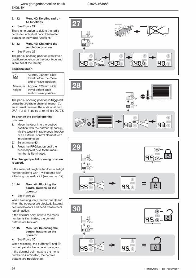
6.1.12 Menu 40: Deleting radio -
All functions
▶ See Figure 27
There is no option to delete the radio codes for individual hand transmitter buttons or individual functions.
6.1.13 Menu 43: Changing the
ventilation position
▶ See Figure 28
The partial opening position (ventilation position) depends on the door type and is pre-set at the factory.
Sectional door:
Approx. 260 mm slide travel before the Close end-of-travel position.
Minimum height
Approx. 120 mm slide travel before each end-of-travel position.
The partial opening position is triggered using the 3rd radio channel (menu 13), an external receiver, the additional print UAP 1 or an impulse at terminals 20 / 23.
To change the partial opening
position:
1. Move the door into the desired position with the buttons and , via the taught-in radio code impulse or an external control element with impulse function.
2. Select menu 43.3. Press the PRG button until the
decimal point next to the menu number is illuminated.
The changed partial opening position
is saved.
If the selected height is too low, a 2-digit number starting with 1 will appear with a flashing decimal point (see section 17).
6.1.14 Menu 44: Blocking the
control buttons on the
operator
▶ See Figure 29
When blocking, only the buttons and on the operator are blocked. External
control elements and hand transmitters remain active.If the decimal point next to the menu number is illuminated, the control buttons are blocked.
6.1.15 Menu 45: Releasing the
control buttons on the
operator
▶ See Figure 30
When releasing, the buttons and on the operator become active again.If the decimal point next to the menu number is illuminated, the control buttons are not blocked.
ENGLISH
www.garagedoorsonline.co.uk 01926 463888
TR10A108-E RE / 03.2017 35
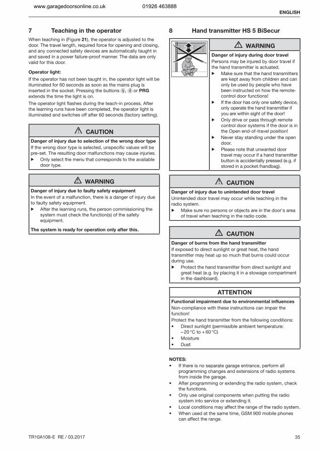
7 Teaching in the operator
When teaching in (Figure 21), the operator is adjusted to the door. The travel length, required force for opening and closing, and any connected safety devices are automatically taught in and saved in a power failure-proof manner. The data are only valid for this door.
Operator light:
If the operator has not been taught in, the operator light will be illuminated for 60 seconds as soon as the mains plug is inserted in the socket. Pressing the buttons , or PRG extends the time the light is on.The operator light flashes during the teach-in process. After the learning runs have been completed, the operator light is illuminated and switches off after 60 seconds (factory setting).
CAUTION
Danger of injury due to selection of the wrong door type
If the wrong door type is selected, unspecific values will be pre-set. The resulting door malfunctions may cause injuries.▶ Only select the menu that corresponds to the available
door type.
WARNING
Danger of injury due to faulty safety equipment
In the event of a malfunction, there is a danger of injury due to faulty safety equipment.▶ After the learning runs, the person commissioning the
system must check the function(s) of the safety equipment.
The system is ready for operation only after this.
8 Hand transmitter HS 5 BiSecur
WARNING
Danger of injury during door travel
Persons may be injured by door travel if the hand transmitter is actuated.▶ Make sure that the hand transmitters
are kept away from children and can only be used by people who have been instructed on how the remote-control door functions!
▶ If the door has only one safety device, only operate the hand transmitter if you are within sight of the door!
▶ Only drive or pass through remote control door systems if the door is in the Open end-of-travel position!
▶ Never stay standing under the open door.
▶ Please note that unwanted door travel may occur if a hand transmitter button is accidentally pressed (e.g. if stored in a pocket /handbag).
CAUTION
Danger of injury due to unintended door travel
Unintended door travel may occur while teaching in the radio system.▶ Make sure no persons or objects are in the door's area
of travel when teaching in the radio code.
CAUTION
Danger of burns from the hand transmitter
If exposed to direct sunlight or great heat, the hand transmitter may heat up so much that burns could occur during use.▶ Protect the hand transmitter from direct sunlight and
great heat (e.g. by placing it in a stowage compartment in the dashboard).
ATTENTION
Functional impairment due to environmental influences
Non-compliance with these instructions can impair the function!Protect the hand transmitter from the following conditions:
Direct sunlight (permissible ambient temperature: – 20 °C to + 60 °C)MoistureDust
NOTES:
If there is no separate garage entrance, perform all programming changes and extensions of radio systems from inside the garage.After programming or extending the radio system, check the functions.Only use original components when putting the radio system into service or extending it.Local conditions may affect the range of the radio system.When used at the same time, GSM 900 mobile phones can affect the range.
ENGLISH
www.garagedoorsonline.co.uk 01926 463888
36 TR10A108-E RE / 03.2017
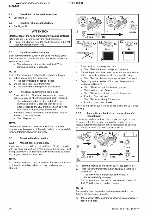
8.1 Description of the hand transmitter
▶ See Figure 20
8.2 Inserting / changing the battery
▶ See Figure 20
ATTENTION
Destruction of the hand transmitter by leaking batteries
Batteries can leak and destroy the hand transmitter.▶ Remove the battery from the hand transmitter if it is not
used for a long period of time.
8.3 Hand transmitter operation
Each hand transmitter button is assigned to a radio code. Press the button of the hand transmitter whose radio code you want to transmit.
– The radio code is transmitted and the LED is illuminated blue for 2 seconds.
NOTE:
If the battery is almost empty, the LED flashes red twicea. before transmitting the radio code.
▶ The battery should be replaced soon.a. and the radio code is not transmitted.
▶ The battery must be replaced immediately.
8.4 Inheriting / transmitting a radio code
1. Press the button of the hand transmitter whose radio code you want to inherit/transmit and keep it pressed.– The radio code is transmitted and the LED is
illuminated blue for 2 seconds then goes out.– After 5 seconds, the LED alternates flashing in red
and blue; the radio code is transmitted.2. If the radio code is transmitted and accepted, release
the hand transmitter button.– The LED goes out.
NOTE:
You have 15 seconds to inherit / transmit the code. The process must be repeated if the radio code is not successfully inherited / transmitted within this time.
8.5 Querying the door position
8.5.1 Manual door position query
A query of the current door position (Open / Close) is possible with this hand transmitter. For this purpose, the operator must be equipped with a bi-directional radio module and be within the range of the hand transmitter.
NOTE:
If a hand transmission button is pressed that does not actuate a bi-directional radio module, the door position query is aborted.
1. Press the door position query button.– The LED is illuminated orange for 5 seconds.
2. Within this period of time, press the hand transmitter button of the door system whose position you want to query.– The LED slowly flashes in orange for up to 5 seconds.
3. Depending on the position of the door, the respective feedback will be sent.a. The LED flashes rapidly 4 times in orange.– The operator is out of reach.b. The LED flashes rapidly in green for 3 seconds.– Position: Door is closedc. The LED flashes slowly 3 times in red.– Position: Door is not closed.
A new door position query is only possible after the LED stops flashing.
8.5.2 Automatic feedback of the door position after
manual query
If the same hand transmitter button is pressed again within 5 seconds after the manual door position query, you will receive automatic feedback on the door position as soon as the door has reached an end-of-travel position.
1. Perform a manual door position query, see section 8.5.1.2. Press the hand transmitter button again as described in
section 8.5.1, 2.– The radio code is transmitted and the LED is
illuminated briefly in orange.3. The position of the door will be queried every 5 seconds;
the LED is illuminated briefly in orange.
NOTE:
Pressing the hand transmitter button again activates door travel if the door is not in motion.
4. If the position of the operator is known, it is automatically transmitted back.
ENGLISH
www.garagedoorsonline.co.uk 01926 463888
TR10A108-E RE / 03.2017 37
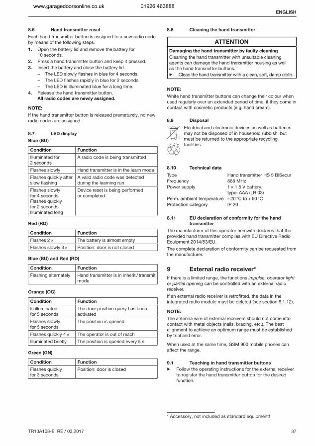
8.6 Hand transmitter reset
Each hand transmitter button is assigned to a new radio code by means of the following steps.1. Open the battery lid and remove the battery for
10 seconds.2. Press a hand transmitter button and keep it pressed.3. Insert the battery and close the battery lid.
– The LED slowly flashes in blue for 4 seconds.– The LED flashes rapidly in blue for 2 seconds.– The LED is illuminated blue for a long time.
4. Release the hand transmitter button.All radio codes are newly assigned.
NOTE:
If the hand transmitter button is released prematurely, no new radio codes are assigned.
8.7 LED display
Blue (BU)
Condition Function
Illuminated for 2 seconds
A radio code is being transmitted
Flashes slowly Hand transmitter is in the learn modeFlashes quickly after slow flashing
A valid radio code was detected during the learning run
Flashes slowly for 4 secondsFlashes quickly for 2 secondsIlluminated long
Device reset is being performed or completed
Red (RD)
Condition Function
Flashes 2 × The battery is almost emptyFlashes slowly 3 × Position: door is not closed
Blue (BU) and Red (RD)
Condition Function
Flashing alternately Hand transmitter is in inherit / transmit mode
Orange (OG)
Condition Function
Is illuminated for 5 seconds
The door position query has been activated
Flashes slowly for 5 seconds
The position is queried
Flashes quickly 4 × The operator is out of reachIlluminated briefly The position is queried every 5 s
Green (GN)
Condition Function
Flashes quickly for 3 seconds
Position: door is closed
8.8 Cleaning the hand transmitter
ATTENTION
Damaging the hand transmitter by faulty cleaning
Cleaning the hand transmitter with unsuitable cleaning agents can damage the hand transmitter housing as well as the hand transmitter buttons.▶ Clean the hand transmitter with a clean, soft, damp cloth.
NOTE:
White hand transmitter buttons can change their colour when used regularly over an extended period of time, if they come in contact with cosmetic products (e.g. hand cream).
8.9 Disposal
Electrical and electronic devices as well as batteries may not be disposed of in household rubbish, but must be returned to the appropriate recycling facilities.
8.10 Technical data
Type Hand transmitter HS 5 BiSecurFrequency 868 MHzPower supply 1 × 1.5 V battery,
type: AAA (LR 03)Perm. ambient temperature – 20 °C to + 60 °CProtection category IP 20
8.11 EU declaration of conformity for the hand
transmitter
The manufacturer of this operator herewith declares that the provided hand transmitter complies with EU Directive Radio Equipment 2014/53/EU.The complete declaration of conformity can be requested from the manufacturer.
9 External radio receiver*
If there is a limited range, the functions impulse, operator light or partial opening can be controlled with an external radio receiver.If an external radio receiver is retrofitted, the data in the integrated radio module must be deleted (see section 6.1.12).
NOTE:
The antenna wire of external receivers should not come into contact with metal objects (nails, bracing, etc.). The best alignment to achieve an optimum range must be established by trial and error.
When used at the same time, GSM 900 mobile phones can affect the range.
9.1 Teaching in hand transmitter buttons
▶ Follow the operating instructions for the external receiver to register the hand transmitter button for the desired function.
* Accessory, not included as standard equipment!
ENGLISH
www.garagedoorsonline.co.uk 01926 463888
38 TR10A108-E RE / 03.2017
9.2 EU Declaration of Conformity for Receivers
The manufacturer of this operator herewith declares that the integrated receiver complies with EU Directive Radio Equipment 2014/53/EU.The complete declaration of conformity can be requested from the manufacturer.
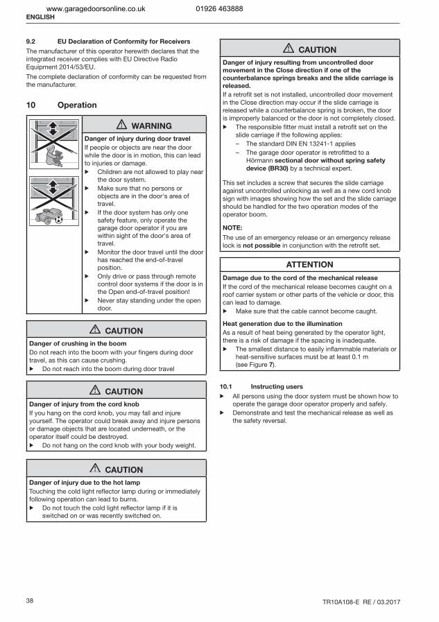
10 Operation
WARNING
Danger of injury during door travel
If people or objects are near the door while the door is in motion, this can lead to injuries or damage.▶ Children are not allowed to play near
the door system.▶ Make sure that no persons or
objects are in the door's area of travel.
▶ If the door system has only one safety feature, only operate the garage door operator if you are within sight of the door's area of travel.
▶ Monitor the door travel until the door has reached the end-of-travel position.
▶ Only drive or pass through remote control door systems if the door is in the Open end-of-travel position!
▶ Never stay standing under the open door.
CAUTION
Danger of crushing in the boom
Do not reach into the boom with your fingers during door travel, as this can cause crushing.▶ Do not reach into the boom during door travel
CAUTION
Danger of injury from the cord knob
If you hang on the cord knob, you may fall and injure yourself. The operator could break away and injure persons or damage objects that are located underneath, or the operator itself could be destroyed.▶ Do not hang on the cord knob with your body weight.
CAUTION
Danger of injury due to the hot lamp
Touching the cold light reflector lamp during or immediately following operation can lead to burns.▶ Do not touch the cold light reflector lamp if it is
switched on or was recently switched on.
CAUTION
Danger of injury resulting from uncontrolled door
movement in the Close direction if one of the
counterbalance springs breaks and the slide carriage is
released.
If a retrofit set is not installed, uncontrolled door movement in the Close direction may occur if the slide carriage is released while a counterbalance spring is broken, the door is improperly balanced or the door is not completely closed.▶ The responsible fitter must install a retrofit set on the
slide carriage if the following applies:– The standard DIN EN 13241-1 applies– The garage door operator is retrofitted to a
Hörmann sectional door without spring safety
device (BR30) by a technical expert.
This set includes a screw that secures the slide carriage against uncontrolled unlocking as well as a new cord knob sign with images showing how the set and the slide carriage should be handled for the two operation modes of the operator boom.
NOTE:
The use of an emergency release or an emergency release lock is not possible in conjunction with the retrofit set.
ATTENTION
Damage due to the cord of the mechanical release
If the cord of the mechanical release becomes caught on a roof carrier system or other parts of the vehicle or door, this can lead to damage.▶ Make sure that the cable cannot become caught.
Heat generation due to the illumination
As a result of heat being generated by the operator light, there is a risk of damage if the spacing is inadequate.▶ The smallest distance to easily inflammable materials or
heat-sensitive surfaces must be at least 0.1 m (see Figure 7).
10.1 Instructing users
▶ All persons using the door system must be shown how to operate the garage door operator properly and safely.
▶ Demonstrate and test the mechanical release as well as the safety reversal.
ENGLISH
www.garagedoorsonline.co.uk 01926 463888
TR10A108-E RE / 03.2017 39
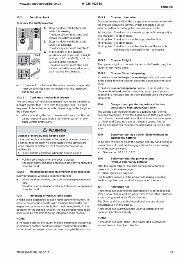
10.2 Function check
To check the safety reversal:
1. Stop the door with both hands while it is closing.The door system must stop and initiate the safety reversal.
2. Stop the door with both hands while it is opening.The door system must switch off.
3. In the centre of the opening, position a test object with a height of approx. 50 mm (SKS) or 16 mm (VL) and close the door.The door system must stop and initiate the safety reversal as soon as it reaches the obstacle.
▶ In the event of a failure of the safety reversal, a specialist must be commissioned immediately for the inspection and repair work.
10.2.1 Cord knob mechanical release
The cord knob for mechanical release may not be installed at a height greater than 1.8 m from the garage floor. The cord may need to be extended on-site, depending on the height of the garage door.▶ When extending the cord, please make sure that the cord
cannot become caught on a roof carrier system or any other vehicle protrusions.
WARNING
Danger of injury by fast-closing door
If the cord knob is actuated while the door is open, there is a danger that the door will close rapidly if the springs are weak, broken or defective, or if the counterbalance is inadequate.▶ Only pull the cord knob when the door is closed.
▶ Pull the cord knob when the door is closed.The door is now released and should be easy to open and close by hand.
10.2.2 Mechanical release by emergency release lock
(Only for garages without a second entrance)▶ When the door is closed, actuate the emergency release
lock.The door is now released and should be easy to open and close by hand.
10.3 Functions of various radio codes
A radio code is assigned to each hand transmitter button. In order to actuate the operator with the hand transmitter, the respective hand transmitter button must be registered in the operator for the desired function, i.e. the corresponding radio code must be transmitted to the integrated radio receiver.
NOTE:
If the radio code for the taught-in hand transmitter button was copied from another hand transmitter, the hand transmitter button must be pressed a second time during initial start-up.
10.3.1 Channel 1 / impulse
During normal operation, the garage door operator works with the impulse sequence control, which is triggered via an external button or the taught-in impulse radio code:1st impulse: The door runs towards an end-of-travel position.2nd impulse: The door stops.3rd impulse: The door runs in the opposite direction.4th impulse: The door stops.5th impulse: The door runs in the direction of the end-of-
travel position selected in the 1st impulse.etc.
10.3.2 Channel 2 / light
The operator light can be switched on and off early using the taught-in light radio code.
10.3.3 Channel 3 / partial opening
If the door is not in the partial opening position, it is moved in the partial opening position using the partial opening radio code.If the door is in partial opening position, it is moved to the Close end-of-travel position using the partial opening radio code and to the Open end-of-travel position using the impulse radio code.
10.4 Garage door operator behaviour after two
consecutive high-speed Open runs
The garage door operator motor is equipped with thermal overload protection. If two fast Open cycles take place within two minutes, the overload protection reduces the travel speed, i.e. Open and Close runs are at the same speed. After a waiting period of two minutes, the next Open run will be fast again.
10.5 Behaviour during a power failure (without an
emergency battery)
To be able to open or close the garage door by hand during a power failure, it must be disengaged from the slide carriage while the door is closed.▶ See section 10.2.1 / 10.2.2
10.6 Behaviour after the power returns
(without emergency battery)
After the power returns, the slide carriage for automatic operation must be re-engaged.▶ See Figure 6 on page 22Due to safety reasons, if the power fails during operation, the first impulse command will always open the door.
10.7 Reference run
A reference run is done if the door position is not recognised after a power failure or if the power limit is activated 3 times in a row during travel in the Close direction.The Open and Close end-of-travel positions are shown simultaneously in the display.A reference run is always in the Open direction and the operator light flashes slowly.
NOTE:
A reference run is not done if the power limit is activated several times in the Open direction.
ENGLISH
www.garagedoorsonline.co.uk 01926 463888
40 TR10A108-E RE / 03.2017
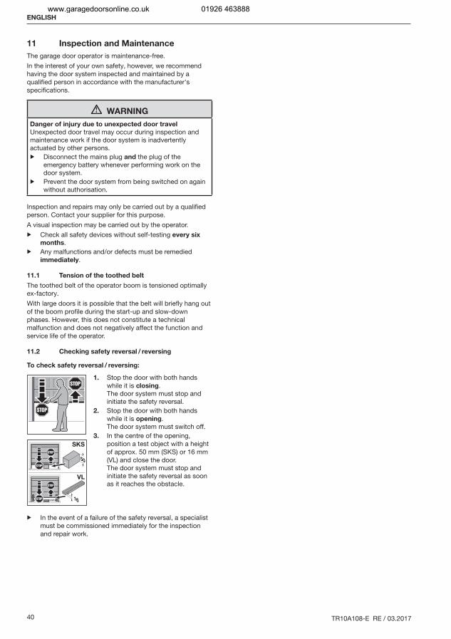
11 Inspection and Maintenance
The garage door operator is maintenance-free.In the interest of your own safety, however, we recommend having the door system inspected and maintained by a qualified person in accordance with the manufacturer's specifications.
WARNING
Danger of injury due to unexpected door travel
Unexpected door travel may occur during inspection and maintenance work if the door system is inadvertently actuated by other persons.▶ Disconnect the mains plug and the plug of the
emergency battery whenever performing work on the door system.
▶ Prevent the door system from being switched on again without authorisation.
Inspection and repairs may only be carried out by a qualified person. Contact your supplier for this purpose.A visual inspection may be carried out by the operator.▶ Check all safety devices without self-testing every six
months.▶ Any malfunctions and/or defects must be remedied
immediately.
11.1 Tension of the toothed belt
The toothed belt of the operator boom is tensioned optimally ex-factory.With large doors it is possible that the belt will briefly hang out of the boom profile during the start-up and slow-down phases. However, this does not constitute a technical malfunction and does not negatively affect the function and service life of the operator.
11.2 Checking safety reversal / reversing
To check safety reversal / reversing:
1. Stop the door with both hands while it is closing.The door system must stop and initiate the safety reversal.
2. Stop the door with both hands while it is opening.The door system must switch off.
3. In the centre of the opening, position a test object with a height of approx. 50 mm (SKS) or 16 mm (VL) and close the door.The door system must stop and initiate the safety reversal as soon as it reaches the obstacle.
▶ In the event of a failure of the safety reversal, a specialist must be commissioned immediately for the inspection and repair work.
ENGLISH
www.garagedoorsonline.co.uk 01926 463888

TR10A108-E RE / 03.2017 41
31
32
11.3 Replacement bulb
CAUTION
Danger of injury due to the hot lamp▶ Do not touch the cold light reflector
lamp if it is switched on or was recently switched on.
Type LED reflector lampSocket GU 5.3Nominal power 3 WNominal voltage 12 V
Type Cold-light reflector lamp with safety glass and UV protection
Socket GU 5.3Nominal power 20 WNominal voltage 12 V
If the light is switched on, an alternating current of 12 V AC is present at the lamp socket.▶ Exchange the light bulb only if the
operator is voltage-free.
12 Factory reset
▶ See Figure 32
To reset to the factory settings:
1. Disconnect the mains plug and, if applicable, the plug of the emergency battery.
2. Press and hold the PRG button.3. Reconnect the mains plug.
The following is illuminated in the display– 8.8. for one second– C for one second– then U
4. Release the PRG button.The operator light flashes once and then remains illuminated.
5. Adjust the operator and teach it in (see section 5).
If the factory reset was not successful, the operator will automatically go back to operation mode.
NOTE:
The taught-in radio codes (impulse/light/partial opening) are not changed.
To delete all radio codes:
▶ See section 6.1.12
ENGLISH
www.garagedoorsonline.co.uk 01926 463888
42 TR10A108-E RE / 03.2017
13 Dismantling and Disposal
NOTE:
When disassembling, observe the applicable regulations regarding occupational safety.
Have a specialist dismantle the garage door operator in the reverse order of these instructions and dispose of it properly.
14 Warranty Conditions
Warranty period
In addition to the statutory warranty provided by the dealer in the sales contract, we grant the following warranty for parts from the date of purchase:
5 years on operator technology, motor and motor control2 years on radio equipment, accessories and special systems
Claims made under the warranty do not extend the warranty period. For replacement parts and repairs the warranty period is six months or at least the remainder of the warranty period.
Prerequisites
The warranty claim only applies in the country where the equipment was purchased. The product must have been purchased through our authorised distribution channels.A claim under this warranty exists only for damage to the object of the contract itself.
Services
For the duration of the warranty we shall eliminate any product defects that are proven to be attributable to a material or manufacturing fault. We pledge to replace free of charge and at our discretion the defective goods with non-defective goods, to carry out repairs, or to grant a price reduction. Replaced parts become our property.Reimbursement of expenditure for dismantling and fitting, testing of parts as well as demands for lost profits and compensation for damages are excluded from the warranty.Damage caused by the following is also excluded:
Improper fitting and connectionImproper initial start-up and operation External factors such as fire, water, abnormal environmental conditionsMechanical damage caused by accidents, falls, impactsNegligent or intentional destruction Normal wear or deficient maintenanceRepairs conducted by unqualified persons Use of non-original partsRemoval or defacing of the data label
15 EC / EU Declaration of
Conformity / Declaration of
Incorporation
(as defined in EC Machinery Directive 2006/42/EC according to annex II, part 1 A for the complete machine or part 1 B for incorporation of partly complete machinery).
Only a combination with specifically approved door types is permissible in order to fit this garage door operator by the end user. These door types can be found in the complete EC/EU Declaration of Conformity in the provided log book.However, if this garage door operator is not combined with an approved door type, the fitter will then be considered a manufacturer of a complete machine.In this case, fitting may only be done by a fitting company, as only they have knowledge of the relevant safety regulations, valid directives and standards, as well as the required testing and measuring devices.The appropriate declaration of incorporation can also be found in the provided log book.
ENGLISH
www.garagedoorsonline.co.uk 01926 463888

TR10A108-E RE / 03.2017 43
16 Technical Data
Mains voltage 230 / 240 V, 50 / 60 HzStand-by Approx. 1 WProtection category Only for dry roomsAutomatic safety cut-out Is automatically taught in for
both directions separatelyEnd-of-travel position
cut-out / force limit
Self-learning, wear-free, as it is designed without mechanical switches, additionally integrated run time limitation to approx. 60 s. Automatic safety cut-out, readjusting at every door run
Rated load See data labelPull and push force See data labelMotor Direct current motor with hall
sensorTransformer With thermal protectionConnection No-screw connection
technology for external equipment with 24 V DC low safety voltage, such as internal and external buttons with impulse operation
Special functions Stop / off switch can be connectedPhotocell or closing edge safety device can be connectedOption relay for warning lamp, additional external illumination can be connected via HCP bus adapter
Quick release Actuated from inside with pull cord in the event of a power failure
Universal fittings For up-and-over doors and sectional doors
Door travel speed In CLOSE direction max. 14 cm / s1)
In OPEN direction max. 22 cm / s1)
Garage door operator
airborne sound emission ≤ 70 dB (A)Operator boom Extremely flat at 30 mm, with
integral door security kit and maintenance-free toothed belt
1) Depending on operator type, door type, door size and door leaf weight
ENGLISH
www.garagedoorsonline.co.uk 01926 463888
44 TR10A108-E RE / 03.2017
17 Display of Errors / Warnings and Operating Conditions
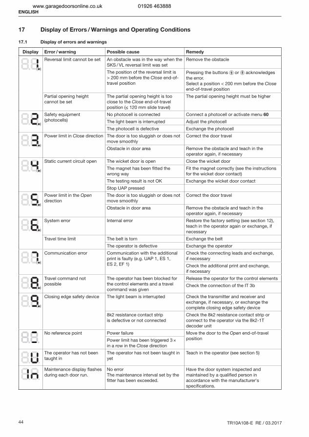
17.1 Display of errors and warnings
Display Error / warning Possible cause Remedy
Reversal limit cannot be set An obstacle was in the way when the SKS / VL reversal limit was set
Remove the obstacle
The position of the reversal limit is > 200 mm before the Close end-of-travel position
Pressing the buttons or acknowledges the error.Select a position < 200 mm before the Close end-of-travel position
Partial opening height cannot be set
The partial opening height is too close to the Close end-of-travel position (≤ 120 mm slide travel)
The partial opening height must be higher
Safety equipment (photocells)
No photocell is connected Connect a photocell or activate menu 60
The light beam is interrupted Adjust the photocellThe photocell is defective Exchange the photocell
Power limit in Close direction The door is too sluggish or does not move smoothly
Correct the door travel
Obstacle in door area Remove the obstacle and teach in the operator again, if necessary
Static current circuit open The wicket door is open Close the wicket doorThe magnet has been fitted the wrong way
Fit the magnet correctly (see the instructions for the wicket door contact)
The testing result is not OK Exchange the wicket door contactStop UAP pressed
Power limit in the Open direction
The door is too sluggish or does not move smoothly
Correct the door travel
Obstacle in door area Remove the obstacle and teach in the operator again, if necessary
System error Internal error Restore the factory setting (see section 12), teach in the operator again or exchange, if necessary
Travel time limit The belt is torn Exchange the beltThe operator is defective Exchange the operator
Communication error Communication with the additional print is faulty (e.g. UAP 1, ES 1, ES 2, EF 1)
Check the connecting leads and exchange, if necessaryCheck the additional print and exchange, if necessary
Travel command not possible
The operator has been blocked for the control elements and a travel command was given
Release the operator for the control elementsCheck the connection of the IT 3b
Closing edge safety device The light beam is interrupted Check the transmitter and receiver and exchange, if necessary, or exchange the complete closing edge safety device
8k2 resistance contact strip is defective or not connected
Check the 8k2 resistance contact strip or connect to the operator via the 8k2-1T decoder unit
No reference point Power failure Move the door to the Open end-of-travel positionPower limit has been triggered 3 ×
in a row in the Close direction The operator has not been taught in
The operator has not been taught in yet
Teach in the operator (see section 5)
Maintenance display flashes during each door run.
No errorThe maintenance interval set by the fitter has been exceeded.
Have the door system inspected and maintained by a qualified person in accordance with the manufacturer's specifications.
ENGLISH
www.garagedoorsonline.co.uk 01926 463888
TR10A108-E RE / 03.2017 45
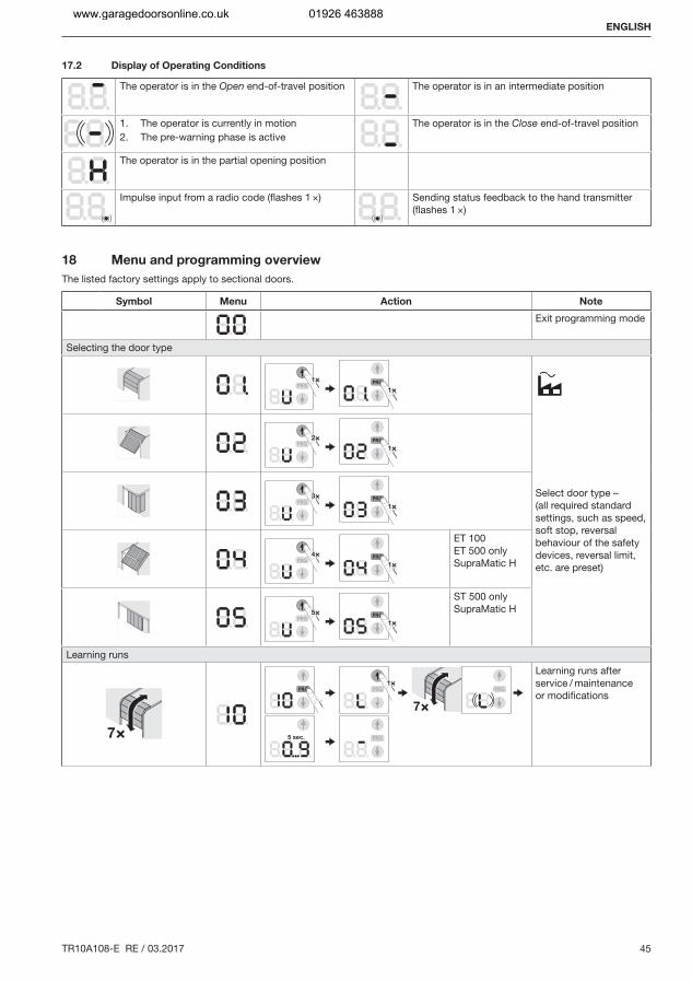
17.2 Display of Operating Conditions
The operator is in the Open end-of-travel position The operator is in an intermediate position
1. The operator is currently in motion2. The pre-warning phase is active
The operator is in the Close end-of-travel position
The operator is in the partial opening position
Impulse input from a radio code (flashes 1 ×) Sending status feedback to the hand transmitter (flashes 1 ×)
18 Menu and programming overview
The listed factory settings apply to sectional doors.
Symbol Menu Action Note
Exit programming mode
Selecting the door type
1
1
2
1
Select door type – (all required standard settings, such as speed, soft stop, reversal behaviour of the safety devices, reversal limit, etc. are preset)
3
1
4
1
ET 100ET 500 only SupraMatic H
5
1
ST 500 only SupraMatic H
Learning runs
7
1
7
5 sec.
Learning runs after service / maintenance or modifications
ENGLISH
www.garagedoorsonline.co.uk 01926 463888
46 TR10A108-E RE / 03.2017
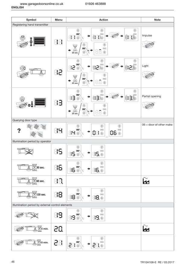
Symbol Menu Action Note
Registering hand transmitter
Impulse
Light
Partial opening
Querying door type
? ...
06 = door of other make
Illumination period by operator
30 sec.
60 sec.
120 sec.
Illumination period by external control elements
5 min.
10 min.
ENGLISH
www.garagedoorsonline.co.uk 01926 463888
TR10A108-E RE / 03.2017 47
Symbol Menu Action Note
Additional functions with relay (HOR 1 or 3rd relay UAP 1)External light on/off(max. illumination time 8 h)
=Function same as operator light
Open end-of-travel position signal
Close end-of-travel position signal
1 sec. Momentary signal on receiving the Open command
Start / advance warning permanent signal
Start / advance warning flashing
Relay picks up during travel
Pre-warning time
5 sec.
Hold-open phase for automatic timer Photocell required
30 sec.
60 sec.
120 sec.
ENGLISH
www.garagedoorsonline.co.uk 01926 463888

48 TR10A108-E RE / 03.2017
Symbol Menu Action Note
180 sec.
Behaviour when button is pressed – hold-open phase for automatic timerPressing a button extends the hold-open phase
Pressing a button cancels the hold-open phase
Deleting all radio codes
5 sec.
All hand transmittersAll functions
Automatic timer – Partial opening Photocell required
1 Std.
Changing the ventilation position
Block/release control buttons
ENGLISH
www.garagedoorsonline.co.uk 01926 463888

TR10A108-E RE / 03.2017 51
www.garagedoorsonline.co.uk 01926 463888