INSTRUCTIONS FOR COMPLETING THE LIFE INSURANCE APPLICATION (For

INDIANA DEPARTMENT OF ENVIRONMENTAL MANAGEMENT
INSTRUCTIONS FOR COMPLETING THE APPLICATION FOR CONSTRUCTION PERMIT FOR PUBLIC WATER SYSTEM - 327 IAC 8-3-3
TYPE OR PRINT ALL ENTRIES. The following numbers refer to the enclosed application.
1. Enter the name of the Public Water System as they are chartered by the State of Indiana and check box if existing or new public water supply system.
2. Enter the Public Water System Identification Number (PWSID) as chartered by the State of Indiana.
3. Enter the name and title of the Public Water System official.
4. Enter the telephone number of the Public Water System, including the area code.
5. Enter the address of the Public Water System.
6. Enter the fax number of the Public Water System.
7. Enter the name of the project.
8. Enter the email address of the PWS Official listed in item 3. NOTE: A valid email address is requested because the issued permit will be emailed to expedite delivery.
9. Enter the county(s) where construction will take place.
10. Indicate the location of the project, which includes the city and reference to adjacent streets or roads.
11. Check the appropriate box(s) indicating who is funding this project.
12-14. Enter the name, mailing address and email address of the local government official applicable to the project. Complete box 12 with Mayor’s information or complete box 13 with Town Board President’s or Council information. Or if project is within county government purview, complete box 14 with County Commissioner’s information.
15. The professional engineer, licensed professional geologist, or licensed well driller must check the box indicating they agree to the certification statement listed. All plans, specifications and applications must be prepared by or under the direct supervision of a professional engineer registered in Indiana, except when 327 IAC 8-3-2.1 applies. For small transient (serving 250 or fewer individuals per day) and small non-transient (serving 100 or fewer individuals per day) public water systems not utilizing surface water or ground water under the direct influence of surface water at its source and are not a county, city, town, township, a school corporation or any other political subdivision, the application, plans and specifications may be certified by a professional engineer, licensed well driller or a license professional geologist. If not for sure, submit your question to the Permits Section via email at [email protected] or by calling (317) 234-7425.
16. The professional engineer, licensed professional geologist, or licensed well driller responsible for the design of the project will put his/her seal and/or license number in this box. This person shall complete Attachment’s A, B, C, D and E, as applicable.
17. Signature and printed name of the professional engineer, licensed professional geologist, or licensed well driller
certifying the application, plans and specifications. 18. Enter email address of the professional engineer, licensed professional geologist, or licensed well driller certifying
the application, plans and specifications. NOTE: A valid email address is requested because the issued permit will be emailed to expedite delivery.
19. Enter telephone number for the person in Box 17.
Over
Example: "Bowling Green (city), Madison Street, one block east of Eel River, along State Road 46"
20. Fax number for the person in Box 17.
21. Name and address of the business the person from Box 17 is affiliated with, if applicable.
22. If project contains water main construction, check box and complete Attachment A.
23. If project contains well construction, check box and complete Attachment B. 24. If project contains pump construction, check box and complete Attachment C. 25. If project contains storage facility construction, check box and complete Attachment D. 26. If project contains chemical addition construction, check box and complete Attachment E. 27. If project contains treatment facility construction, check box and complete all applicable Attachments. 28. Check appropriate boxes to questions concerning plans and specifications. NOTE: You may submit the
completed application, specifications and drawings digitally at [email protected]. Electronic documents must be legible and in PDF format. The drawings and the cover page of the specifications must contain certifier’s signature and seal if applicable. If a construction permit processing fee is required, follow the instructions provided at number 29.
29. Check 327 IAC 8-3-7(a) to see if a processing fee is required. Exempt organizations are both a governmental entity
and one of the listed categories. If you are not a governmental entity, then you are not exempt from the construction permit processing fee. If not sure, contact the Permits Section via email at [email protected] or by calling (317) 234-7425, prior to submitting the permit application. If a processing fee is required, check the appropriate box(es) and submit payment using one (1) of the following options:
A. Make check/money order payable to IDEM (Acct.#3240-414000-140000) and mail with a copy of the
completed first page of the permit application to: IDEM PO Box 3295 Indianapolis, IN 46206-3295
B. Remit by ACH to: ABA#: 071921891 Bank Account Number: 4620695315 Bank Account Name: State of Indiana
AND send a copy of the first page of the completed permit application, amount of payment and payment date to [email protected].
C. To pay by credit card, call (317) 234-3099 and leave the information requested in the telephone message
and email copy of the first page of the completed permit application, the amount of payment and payment date to [email protected].
Public Notification: IDEM typically provides a thirty (30) day public comment period on all drinking water projects requiring an individual construction permit. Public notice is provided on IDEM’s Public Notice website, which is located at: http://www.in.gov/idem/5474.htm. The notice includes information on the project, as well as where to obtain the proposed permit and related documents, and how to submit comments. The permit is effective immediately upon issuance after the public notice period has ended. Notice of Decision: Another option for public notice is written notification (Notice of Decision) of issuance of the construction permit to potentially affected parties, as defined by IC 4-21.5-3-7. For this option, a complete list of potentially affected persons along with a mailing label for each must be submitted with the permit application. The permit is effective eighteen (18) days from the date of issuance. Prior to requesting this notice option, please contact the Drinking Water Branch at (317) 234-7425.

APPLICATION FOR CONSTRUCTION PERMIT FOR PUBLIC WATER SYSTEM - 327 IAC 8-3-3
FOR AGENCY USEPermit number
State Form 35058 (R8 / 4-15) Approved by State Board of Accounts, 2015 Indiana Department of Environmental Management Drinking Water Branch
WS -
1. Name of Public Water System (PWS) New Existing
2. PWSID number (IN#######)
3. Name of PWS official and title (i.e. Superintendent, Utility Engineer/Manager, Owner…) 4. Telephone number of PWS ((###) ###-####) ( )
5. Address of PWS (number and street, city, state, and ZIP code) 6. FAX number of PWS ((###) ###-####) ( )
7. Name of project 8. E-mail address of PWS official
9. County(s) of project 10. Location of project
11. Source of funding for the project PWS Developer Dept. of Commerce (DOC) State Revolving Fund Other 12. Name, address (number and street, city, state,
and ZIP code) and e-mail address of Local Government Official – Mayor
13. Name, address (number and street, city, state, and ZIP code) and e-mail address of Town Board or Council President
14. Name, address (number and street, city, state,and ZIP code) and e-mail address of County Commissioner (if any)
15. Certification by Professional Engineer / Licensed Geologist / Licensed Well Driller (see instructions)
I hereby certify that I am familiar with the information contained in this application and that to the best of my knowledge and belief, such information is true, complete and accurate. I further certify that construction of the proposed project following the application, plans and specifications will produce drinking water of satisfactory quality in accordance with 327 IAC 8.
16. P.E. seal / Geologist License number / Well Driller License number
17. Signature of Professional Engineer / Licensed Professional Geologist / Licensed Well Driller and their printed name
18. E-mail address of box 17
19. Telephone number of box 17 ( )
20. FAX number of box 17 ( )
21. Name and address (number and street, city, state, and ZIP code) of firm box 17 is affiliated with (if applicable)
Check all that apply:
22. For water main construction: Complete Attachment A 23. For well construction: Complete Attachment B 24. For any pumping facility construction: Complete Attachment C 25. For storage facility construction: Complete Attachment D 26. For chemical addition: Complete Attachment E 27. For treatment facility construction: Complete all applicable Attachments
FOR AGENCY USE Date received by IDEM (month, day, year)
28. Plans and Specifications (May be submitted electronically – see note at end of instructions.)
A. Is one complete set of legible plans submitted? Yes No B. Is a set of specifications submitted with the cover page signed and sealed by P.E.? Yes No On IDEM file
C. Is each and every page of the plans signed and sealed by a professional engineer?
Yes No
Page 1
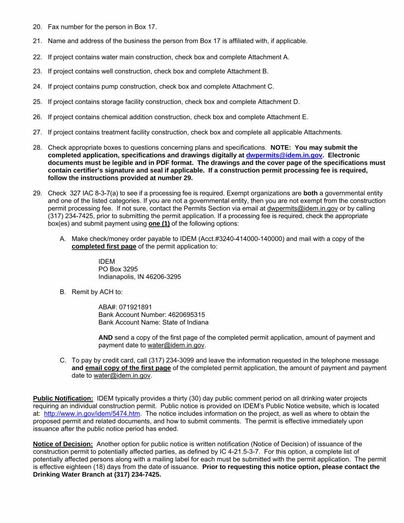
29. Construction Permit Processing Fee Schedule
NOTE: THIS APPLICATION WILL BE RETURNED IF NOT ACCOMPANIED WITH THE REQUIRED FEE UNLESS THE APPLICANT IS AN EXEMPTED GOVERNMENT ENTITY, WHICH INCLUDES A COUNTY, MUNICIPALITY, OR TOWNSHIP WHICH IS DEFINED AS A UNIT UNDER IC 36-1-2-23, A NONPROFIT ORGANIZATION , A CONSERVANCY DISTRICT, A SCHOOL CORPORATION, OR REGIONAL WATER OR SEWAGE DISTRICT [327 IAC 8-3-7(a)]. A. New public water system treatment plant C. Other water treatment facilities Groundwater: Wells $ 500 Up to 500,000 gallons per day $ 875 Pump or pump station $ 100 Greater than 500,000 gallons per day $ 1,750 Chemical addition $ 250 Surface water: Storage Tank $ 200 Up to 500,000 gallons per day $ 1,250 Greater than 500,000 gallons per day $ 2,500 Miscellaneous process modification B. Public water system treatment plant expansion $ 50 per process Up to fifty percent (50%) design capacity D. All water distribution system Up to 500,000 gallons per day $ 625 Up to 2,500 linear feet $ 0 Greater than 500,000 gallons per day $ 1,250 2,501 - 5,000 linear feet $ 150 Greater than fifty percent (50%) design capacity 5,001 - 10, 000 linear feet $ 250 Up to 500,000 gallons per day $ 1,250 Greater than 10,000 linear feet $ 500 Greater than 500,000 gallons per day $ 2,500
IF A PROCESSING FEE IS REQUIRED, SEE INSTRUCTIONS FOR PAYMENT OPTIONS.
THE COMPLETED APPLICATION MUST BE SUBMITTED ELLECTRONICALLY TO [email protected] OR MAILED TO:
Drinking Water Branch Indiana Department of Environmental Management
100 N. Senate Avenue Indianapolis, Indiana 46204
Attach a list of persons whom you have a reason to believe have a substantial or proprietary interest in this matter, or are potentially affected persons as defined by IC 4-21.5-3-5(b). Failure to notify a person who is later determined to be potentially affected could result in voiding our decision on legal grounds. To ensure conformance with the Indiana Administrative Orders and Procedures Act and to prevent voiding a decision, you must list all such parties and must provide mailing labels for all potentially affected parties. The labels shall read as follows: Name of affected party, Address (number and street or rural route number), City, State and ZIP Code.
I certify, that to the best of my knowledge, I have listed all the potentially affected parties, as defined by IC 4-21.5-3-5(b), known to me and provided mailing labels. If “None” is indicated, it signifies that no such parties exist.
Official signature of Public Water System Date signed (month, day, year)
Printed name and title of official
Page 2

APPLICATION FOR CONSTRUCTION PERMIT FOR PUBLIC WATER SYSTEM - 327 IAC 8-3-3 State Form 35058 (R8 / 4-15) Approved by State Board of Accounts, 2015 Indiana Department of Environmental Management Drinking Water Branch
Attachment A
Water Main Construction
1. Water Main Construction
A. This construction is (Check all that apply.)
New Replacement Relocation B. Water Main Description
Length Material Type Diameter Class Pressure Rating Types of Joints
Total Length =
C. Depth of cover per frost penetration table under 327 IAC 8-3.2-17(d)
inches
D. Is the proposed main providing fire protection?
Yes No
E. Will the main be pressure/leak tested per American Water Works Association (AWWA) C600-10? Yes No If No, please attach a detailed description of the pressure/leak testing method.
F. Will the main be disinfected per AWWA, C651-14? Yes No If No, please attach a detailed description of the disinfection method.
G. Will fire hydrants and water mains at each tee, bend, and dead end be blocked or anchored per AWWA, C600-10? Yes No If No, please attach a detailed description of the method.
2. Design Specifics and Plans
A. Minimum horizontal clearance between water mains and sewers (including storm drains) shall be ten (10) feet (ref. 327 IAC 8-3.2-9).
Yes No
B. Minimum vertical clearance between water mains and sewers (including storm drain) shall be eighteen (18) inches (ref. 327 IAC 8-3.2-9)
Yes No
C. Are there any stream crossings? Yes No
D. What is the maximum spacing between valves? E. What is the maximum spacing between hydrants?
F. Is there a history of external corrosion problems with buried pipe in the project area? Yes No If Yes, provide copy of any corrosion study and explain corrosion protection measures. 3. System Design Data
A. System's total plant capacity: (Not firm capacity)
GPD
B. Number of existing service connections served by Public Water System
C. Number of service connections to be served by the proposed water main extension
D. Demand of Water Main Extension
1. Fire Flow gpm
2. Unit Peak Daily Demand (per new customer) gpm
3. Total Peak Daily Demand with Fire Flow of new water main extension [(Unit Peak Daily Demand x number gpm of customers) + fire flow]
E. Pressure at the "Total Peak Daily Demand, No Fire Flow" flow rate at the point of connection psi
F. Pressure at the "Total Peak Daily Demand with Fire Flow" flow rate at the point of connection psi
Page 1 Over
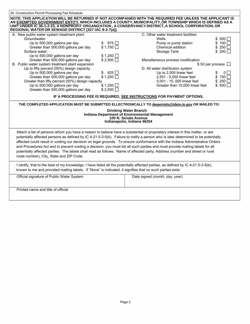
I. The Public Water System's five (5) highest demand days in previous two (2) years. Demand (GPD) Date (month, day, year)
1.
2.
3.
4.
5.
Two (2) year Average Daily Demand (average of 1 through 5 above) GPD
4. Summary of Flow Test Data (data must be attached)
1. Date of flow test (month, day, year)
2. Static pressure at flow test location psi
3. Flow test flow rate gpm
4. Residual pressure at flow test flow rate psi
SKETCH THE FOLLOWING: Show the relationship between fire flow test location and the point of connection of proposed water main. Include all water main piping information including lengths, diameters and material type. Include the elevations at both fire flow location and point of connection. Show north arrow. No scale is necessary if pipe lengths are noted.
5. This flow test was taken at: Fire Hydrants (wide open) Fire Hydrants (open to sustain 20 psi residual pressure) Flushing Hydrants (wide open)
Tank level during test _______________ Booster pump within the pressure zone of the proposed water main ____ On _____ Off
5. Water Main Extension Hydraulic Calculation
Enclosed Hydraulic Model or Enclosed Hydraulic Calculations
6. Alternative Technical Standard (Check all that apply.)
This application cites pre-approved alternative technical standards (copy attached).
This application proposes alternative technical standards (attached demonstration per 327 IAC 8-3.2-20)
No alternative technical standards are utilized in this project.
Page 2

7. Certification to Furnish Water (This section must be completed.)
The has agreed to furnish
City, Town, Village, Water Company or Water Authority
water to the area in which water main extensions are proposed by Name the person representing the funding entity of the construction project (e.g., developer)
according to plans titled " " and prepared by
. The undersigned acknowledges the public
Name of Engineering Firm
water supplier's responsibility for examining the plans and specifications to determine that the proposed extensions meet local rules or laws,
regulations and ordinances.
Date signed (month, day, year) By: (signature of Public Water System official)
Name of Public Water System Title
Page 3
APPLICATION FOR CONSTRUCTION PERMIT FOR
Well ConstructionPUBLIC WATER SYSTEM - 327 IAC 8-3-3 Attachment B
State Form 35058 (R8 / 4-15) Approved by State Board of Accounts, 2015 Indiana Department of Environmental Management Drinking Water Branch
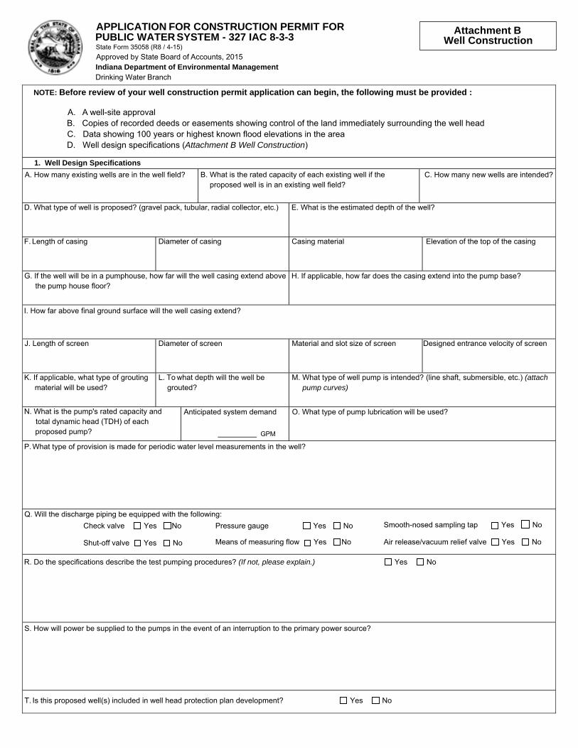
NOTE: Before review of your well construction permit application can begin, the following must be provided :
A. A well-site approval B. Copies of recorded deeds or easements showing control of the land immediately surrounding the well head C. Data showing 100 years or highest known flood elevations in the area D. Well design specifications (Attachment B Well Construction)
1. Well Design Specifications A. How many existing wells are in the well field? B. What is the rated capacity of each existing well if the
proposed well is in an existing well field? C. How many new wells are intended?
D. What type of well is proposed? (gravel pack, tubular, radial collector, etc.) E. What is the estimated depth of the well?
F. Length of casing Diameter of casing Casing material Elevation of the top of the casing
G. If the well will be in a pumphouse, how far will the well casing extend above the pump house floor?
H. If applicable, how far does the casing extend into the pump base?
I. How far above final ground surface will the well casing extend?
J. Length of screen Diameter of screen Material and slot size of screen Designed entrance velocity of screen
K. If applicable, what type of grouting material will be used?
L. To what depth will the well be grouted?
M. What type of well pump is intended? (line shaft, submersible, etc.) (attach pump curves)
N. What is the pump's rated capacity and total dynamic head (TDH) of each proposed pump?
Anticipated system demand
GPM
O. What type of pump lubrication will be used?
P. What type of provision is made for periodic water level measurements in the well?
Q. Will the discharge piping be equipped with the following: Check valve Yes No Pressure gauge Yes No Smooth-nosed sampling tap Yes No
Shut-off valve Yes No Means of measuring flow Yes No Air release/vacuum relief valve Yes No
R. Do the specifications describe the test pumping procedures? (If not, please explain.) Yes No
S. How will power be supplied to the pumps in the event of an interruption to the primary power source?
T. Is this proposed well(s) included in well head protection plan development? Yes No

APPLICATION FOR CONSTRUCTION PERMIT FOR PUBLIC WATER SYSTEM - 327 IAC 8-3-3 State Form 35058 (R8 / 4-15) Approved by State Board of Accounts, 2015 Indiana Department of Environmental Management Drinking Water Branch
Attachment C
Pumping Station
A. What is the 100 year or highest known flood elevation in the area? B. What is the pumphouse floor elevation?
C. What is the elevation of the finished grade at the pumphouse location?
D. How many pumps are provided? (attach pump curves)
E. What peak demand (gpm) is the pump(s) designed for?
F. What is the rated capacity (gpm) of each proposed pump and total dynamic head (TDH)?
G. How will power be supplied to the pumps in the event of an interruption to the primary power source?
H. What kind of monitoring will be provided and what is the form of communication?
I. Does each pump have a pressure gauge on its discharge line and a compound gauge on its suction line? Yes No
J. Is there a low suction cut-off control?
Yes No
If Yes, what is its setting?
K. How is the total discharge of the pump(s) measured?
L. Does the pump have a check valve?
Yes No
If Yes, where is the check valve located?

APPLICATION FOR CONSTRUCTION PERMIT FOR
Storage FacilitiesPUBLIC WATER SYSTEM - 327 IAC 8-3-3 Attachment D
State Form 35058 (R8 / 4-15) Approved by State Board of Accounts, 2015 Indiana Department of Environmental Management Drinking Water Branch
A. What is the 100 year or highest known flood elevation in the area? B. What type of storage facility is proposed? (standpipe, elevated, ground, etc.)
C. What is the capacity of the storage facility? D. What is the elevation at the base of the storage facility?
E. What is the purpose of the water storage facility?
a. Volume b. Pressure c. Fire protection
F. Are there other existing water storage tanks within the system? If so, what is the total storage capacity of the system? Yes No
G. What is the size (gallons) of the existing tank(s) and overflow elevation? H. What is the average daily consumption of the system?
I. How is the storage facility isolated from the distribution system?
J. What is the filling rate of the storage facility?
K. What size is the overflow pipe? Is the overflow pipe screened?
Yes No
What size screen?
L. What is expected to be the operating head range of the storage facility?
M. What provisions have been made to monitor water levels in the storage facility?
N. What provisions have been made to allow for draining of the storage facility?
O. Where are the sampling taps located?
P. How is the storage facility protected from trespassers, vandalism and sabotage?
Site fenced Yes No Alarm Yes No
Ladder guard Yes No Lighting Yes No
Hatch locked Yes No
Q. Is cathodic protection being used?
R. How is the storage facility being protected from freezing?
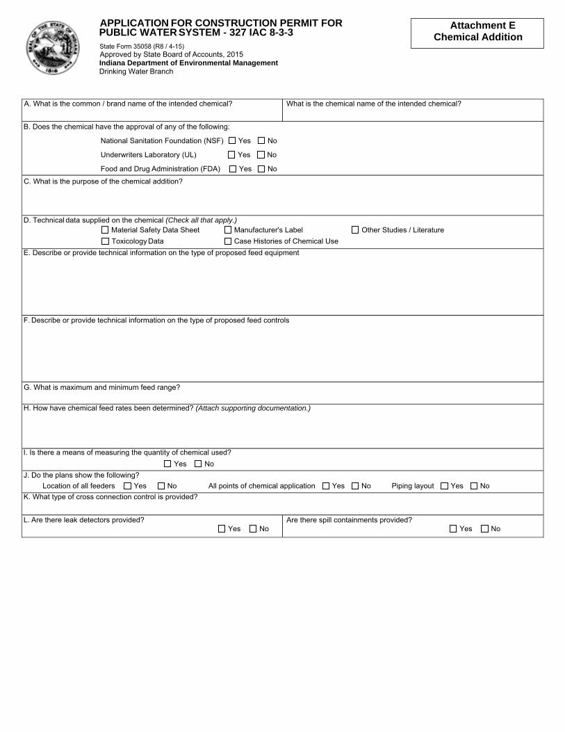
PUBLIC WATER SYSTEM - 327 IAC 8-3-3APPLICATION FOR CONSTRUCTION PERMIT FOR Attachment E
Chemical Addition State Form 35058 (R8 / 4-15) Approved by State Board of Accounts, 2015 Indiana Department of Environmental Management Drinking Water Branch
A. What is the common / brand name of the intended chemical? What is the chemical name of the intended chemical?
B. Does the chemical have the approval of any of the following:
National Sanitation Foundation (NSF) Yes No
Underwriters Laboratory (UL) Yes No
Food and Drug Administration (FDA) Yes No
C. What is the purpose of the chemical addition?
D. Technical data supplied on the chemical (Check all that apply.) Material Safety Data Sheet Manufacturer's Label Other Studies / Literature Toxicology Data Case Histories of Chemical Use
E. Describe or provide technical information on the type of proposed feed equipment
F. Describe or provide technical information on the type of proposed feed controls
G. What is maximum and minimum feed range?
H. How have chemical feed rates been determined? (Attach supporting documentation.)
I. Is there a means of measuring the quantity of chemical used? Yes No
J. Do the plans show the following? Location of all feeders Yes No All points of chemical application Yes No Piping layout Yes No K. What type of cross connection control is provided?
L. Are there leak detectors provided? Yes No
Are there spill containments provided? Yes No