INSTRUCTIONS FOR 200A 230/400V Turbo Arc Welder · INSTRUCTIONS FOR 200A 230/400V Turbo Arc Welder...
24
INSTRUCTIONS FOR 200A 230/400V Turbo Arc Welder Stock No.83403 Part No.AW200T IMPORTANT: PLEASE READ THESE INSTRUCTIONS CAREFULLY TO ENSURE THE SAFE AND EFFECTIVE USE OF THIS PRODUCT. GENERAL INFORMATION These instructions accompanying the product are the original instructions. This document is part of the product, keep it for the life of the product passing it on to any subsequent holder of the product. Read all these instructions before assembling, operating or maintaining this product. This manual has been compiled by Draper Tools describing the purpose for which the product has been designed, and contains all the necessary information to ensure its correct and safe use. By following all the general safety instructions contained in this manual, it will ensure both product and operator safety, together with longer life of the product itself. AlI photographs and drawings in this manual are supplied by Draper Tools to help illustrate the operation of the product. Whilst every effort has been made to ensure the accuracy of information contained in this manual, the Draper Tools policy of continuous improvement determines the right to make modifications without prior warning.
Transcript of INSTRUCTIONS FOR 200A 230/400V Turbo Arc Welder · INSTRUCTIONS FOR 200A 230/400V Turbo Arc Welder...

INSTRUCTIONS FOR
200A 230/400VTurbo Arc Welder
Stock No.83403 Part No.AW200T
IMPORTANT: PLEASE READ THESE INSTRUCTIONS CAREFULLY TO ENSURE THE SAFE AND EFFECTIVE USE OF THIS PRODUCT.
GENERAL INFORMATION
These instructions accompanying the product are the original instructions. This document is part of the product, keep it for the life of the product passing it on to any subsequent holder of the product. Read all these instructions before assembling, operating or maintaining this product.This manual has been compiled by Draper Tools describing the purpose for which the product has been designed, and contains all the necessary information to ensure its correct and safe use. By following all the general safety instructions contained in this manual, it will ensure both product and operator safety, together with longer life of the product itself.AlI photographs and drawings in this manual are supplied by Draper Tools to help illustrate the operation of the product.Whilst every effort has been made to ensure the accuracy of information contained in this manual, the Draper Tools policy of continuous improvement determines the right to make modifications without prior warning.

1. TITLE PAGE
1.1 INTRODUCTION:USER MANUAL FOR:
200A 230/400V TURBO ARC WELDERStock no. 83403Part no. AW200T
1.2 REVISIONS:
As our user manuals are continually updated, users should make sure that they use the very latest version.
Downloads are available from: http://www.drapertools.com/manuals
DRAPER TOOLS LIMITED WEBSITE: www.drapertools.comHURSLEY ROAD PRODUCT HELPLINE: +44 (0) 23 8049 4344CHANDLER’S FORD GENERAL FAX: +44 (0) 23 8026 0784EASTLEIGHHAMPSHIRESO53 1YFUK
1.3 UNDERSTANDING THIS MANUALS SAFETY CONTENT:
WARNING! Information that draws attention to the risk of injury or death.
CAUTION! Information that draws attention to the risk of damage to the product or surroundings.
1.4 COPYRIGHT © NOTICE:Copyright © Draper Tools Limited.Permission is granted to reproduce this publication for personal & educational use only. Commercial copying, redistribution, hiring or lending is prohibited.No part of this publication may be stored in a retrieval system or transmitted in any other form or means without written permission from Draper Tools Limited.
In all cases this copyright notice must remain intact.
Date first published November 2015.
2. CONTENTS
2.1 CONTENTSPage content Page1 TITLE PAGE 1.1 INTRODUCTION ....................................................................................................2 1.2 REVISION HISTORY................................................................................................2 1.3 UNDERSTANDING THIS MANUAL .......................................................................2 1.4 COPYRIGHT NOTICE..............................................................................................22 CONTENTS 2.1 CONTENTS .............................................................................................................33 GUARANTEE 3.1 GUARANTEE ..........................................................................................................44 INTRODUCTION 4.1 SCOPE ...................................................................................................................5 4.2 SPECIFICATION ......................................................................................................5 4.3 HANDLING & STORAGE ........................................................................................55 HEALTH & SAFETY INFORMATION 5.1 GENERAL SAFETY INSTRUCTIONS FOR POWER TOOL USE .................................6 5.2 GENERAL ARC-WELDER SAFETY WARNINGS ......................................................8 5.3 ADDITIONAL SAFETY INSTRUCTIONS FOR ARC-WELDERS .................................9 5.4 CONNECTION TO THE POWER SUPPLY................................................................106 TECHNICAL DESCRIPTION 6.1 IDENTIFICATION ....................................................................................................117 UNPACKING & CHECKING 7.1 PACKAGING...........................................................................................................12 7.2 WHAT’S IN THE BOX .............................................................................................128 ASSEMBLING THE ARC WELDER 8.1 FITTING THE CARRY/PULL HANDLE......................................................................13 8.2 FITTING THE WHEELS............................................................................................13 8.3 FITTING THE FEET..................................................................................................14 8.4 ASSEMBLING THE FACEMASK ..............................................................................149 SETTING THE ARC WELDER 9.1 RATING PLATE INFORMATION .............................................................................15 9.2 PREPARING THE WELDING CIRCUIT .....................................................................16 9.3 ADJUSTING THE WELDING CURRENT ..................................................................16 9.4 THERMAL CUTOUT SIGNAL .................................................................................16 9.5 RECOMMENDATIONS FOR USE ...........................................................................1710 MAINTENANCE 10.1 MAINTENANCE & PART REPLACEMENT ..............................................................1811 EXPLANATION OF SYMBOLS 11.1 EXPLANATION OF SYMBOLS ................................................................................1912 DISPOSAL 12.1 DISPOSAL...............................................................................................................20
DECLARATION OF CONFORMITY ..........................................................................................ENCLOSED
3
2. CONTENTS
3

3. GUARANTEE
3.1 GUARANTEEDraper tools have been carefully tested and inspected before shipment and are guaranteed to be free from defective materials and workmanship for a period of 12 months from the date of purchase except where tools are hired out when the guarantee period is 90 days from the date of purchase.A proof of purchase must be provided with the tool.Should the machine develop any fault, please return the complete tool to your nearest authorized warranty repair agent or contact Draper Tools Limited, Chandler's Ford, Eastleigh, Hampshire, SO53 1YF. England. Telephone Sales Desk: (023) 8049 4333 or Product Helpline (023) 8049 4344.If upon inspection it is found that the fault occurring is due to defective materials or workmanship, repairs will be carried out free of charge. This guarantee does not apply to normal wear and tear, nor does it cover any damage caused by misuse, careless or unsafe handling, alterations, accident, or repairs attempted or made by any personnel other than the authorised Draper warranty repair agent.NOTE: If the tool is found not to be within the terms of warranty, repairs and carriage charges will be quoted and made accordingly.This guarantee applies in lieu of any other guarantee expressed or implied and variations of its terms are not authorised.Your Draper guarantee is not effective unless you can produce upon request a dated receipt or invoice to verify your proof of purchase within the 12 month period.Please note that this guarantee is an additional benefit and does not affect your statutory rights.Draper Tools Limited
4
4. INTRODUCTION
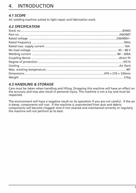
4.1 SCOPEAC welding machine suited to light repair and fabrication work.
4.2 SPECIFICATIONStock no .............................................................................................................................83403Part no .......................................................................................................................... AW200TRated voltage ........................................................................................................... 230/400V~Rated frequency ................................................................................................................ 50HzRated max. supply current ................................................................................................. 16A No load voltage .......................................................................................................... 45 – 48 VWelding current ........................................................................................................ 80 – 200ACoupling device ........................................................................................................... direct fitDegree of protection .........................................................................................................IP21SCooling ..........................................................................................................................Air (fan)Max. working temperature .................................................................................................. 40ºDimensions .................................................................................................470 × 270 × 320mmWeight ............................................................................................................................... 21kg
4.3 HANDLING & STORAGECare must be taken when handling and lifting. Dropping this machine will have an effect on the accuracy and may also result in personal injury. This machine is not a toy and must be respected.
The environment will have a negative result on its operation if you are not careful. If the air is damp, components will rust. If the machine is unprotected from dust and debris; components will become clogged: And if not cleaned and maintained correctly or regularly the machine will not perform at its best.
5

5. HEALTH & SAFETY INFORMATION
5.1 GENERAL SAFETY INSTRUCTIONS FOR POWER TOOL USEWhen using any type of power tool there are steps that should be taken to make sure that you, as the user, remain safe.Common sense and a respect for the tool will help reduce the risk of injury.
Read the instruction manual fully. Do not attempt any operation until you have read and understood this manual.Most important you must know how to safely start and stop this machine, especially in an emergency.
Keep the work area tidy and clean. Attempting to clear clutter from around the machine during use will reduce your concentration. Mess on the floor creates a trip hazard. Any liquid spilt on the floor could result in you slipping.
Find a suitable location. If the machine is bench mounted; the location should provide good natural light or artificial lighting as a replacement. Avoid damp and dust locations as it will have a negative effect on the its performance.If the machine is portable; do not expose to rain. In all cases do not operate power tools near flammable materials.
Beware of electric shock. Avoid contact with earthed surfaces; because they can conduct electricity if there is an electrical fault with the power tool. Always protect the power cable and route it away from danger.
Keep bystanders away. Children, onlookers and passers-by must be restricted from entering the work area for their own protection. The barrier must extend a suitable distance from the tool user.
Unplug and house all power tools that are not in use. A power tool should never be left unattended while connected to the power supply. They must be housed in a suitable location, away locked up and from children.
Do not overload or misuse the tool. All tools are designed for a purpose and are limited to what they are capable of doing. Do not attempt to use a power tool (or modify) for an application it is not designed for. Select a tool appropriate for the size of the job. Overloading a tool will result in tool failure and user injury: This includes the use of accessories.
Dress appropriately. Clothing should be close fitted, with any long hair tired back and jewellery and neck ties removed as they can cause an entanglement risk, resulting in body parts being pulled into the machine. Footwear must be fully enclosed and have a nonslip sole.
6
5. HEALTH & SAFETY INFORMATION
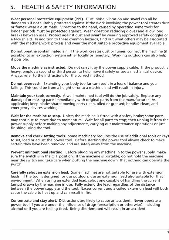
Wear personal protective equipment (PPE). Dust, noise, vibration and swarf can all be dangerous if not suitably protected against. If the work involving the power tool creates dust or fumes; wear a dust mask. Vibration to the hand, caused by operating some tools for longer periods must be protected against. Wear vibration reducing gloves and allow long breaks between uses. Protect against dust and swarf by wearing approved safety goggles or a face shield. In addition to these common hazards, find out what others may be associated with the machine/work process and wear the most suitable protective equipment available.
Do not breathe contaminated air. If the work creates dust or fumes; connect the machine (if possible) to an extraction system either locally or remotely. Working outdoors can also help if possible.
Move the machine as instructed. Do not carry it by the power supply cable. If the product is heavy; employ a second or third person to help move it safely or use a mechanical device. Always refer to the instructions for the correct method.
Do not overreach. Extending your body too far can result in a loss of balance and you falling. This could be from a height or onto a machine and will result in injury.
Maintain your tools correctly. A well maintained tool will do the job safely. Replace any damaged or missing parts immediately with original parts from the manufacturer. As applicable; keep blades sharp; moving parts clean, oiled or greased; handles clean; and emergency devices working.
Wait for the machine to stop. Unless the machine is fitted with a safety brake; some parts may continue to move due to momentum. Wait for all parts to stop; then unplug it from the power supply before making any adjustments, carrying out maintenance operations or just finishing using the tool.
Remove and check setting tools. Some machinery requires the use of additional tools or keys to set, load or adjust the power tool. Before starting the power tool always check to make certain they have been removed and are safely away from the machine.
Prevent unintentional starting. Before plugging any machine in to the power supply, make sure the switch is in the OFF position. If the machine is portable; do not hold the machine near the switch and take care when putting the machine down; that nothing can operate the switch.
Carefully select an extension lead. Some machines are not suitable for use with extension leads. If the tool is designed for use outdoors; use an extension lead also suitable for that environment. When using an extended lead, select one capable of handling the current (amps) drawn by the machine in use. Fully extend the lead regardless of the distance between the power supply and the tool. Excess current and a coiled extension lead will both cause the cable to heat up and can result in fire.
Concentrate and stay alert. Distractions are likely to cause an accident. Never operate a power tool if you are under the influence of drugs (prescription or otherwise), including alcohol or if you are feeling tired. Being disorientated will result in an accident.
7
5. HEALTH & SAFETY INFORMATION
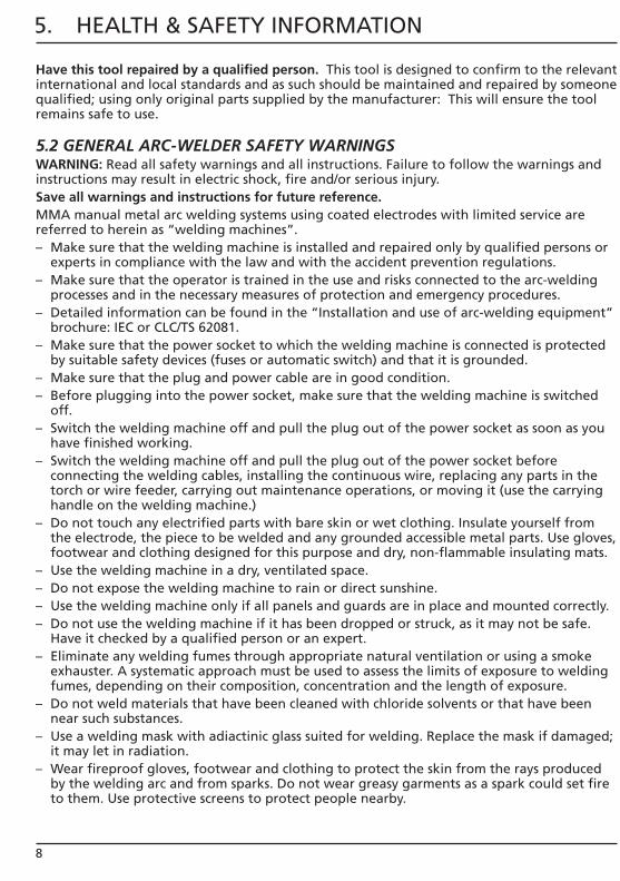
Have this tool repaired by a qualified person. This tool is designed to confirm to the relevant international and local standards and as such should be maintained and repaired by someone qualified; using only original parts supplied by the manufacturer: This will ensure the tool remains safe to use.
5.2 GENERAL ARC-WELDER SAFETY WARNINGSWARNING: Read all safety warnings and all instructions. Failure to follow the warnings and instructions may result in electric shock, fire and/or serious injury. Save all warnings and instructions for future reference.MMA manual metal arc welding systems using coated electrodes with limited service are referred to herein as “welding machines”.– Make sure that the welding machine is installed and repaired only by qualified persons or
experts in compliance with the law and with the accident prevention regulations.– Make sure that the operator is trained in the use and risks connected to the arc-welding
processes and in the necessary measures of protection and emergency procedures.– Detailed information can be found in the “Installation and use of arc-welding equipment”
brochure: IEC or CLC/TS 62081.– Make sure that the power socket to which the welding machine is connected is protected
by suitable safety devices (fuses or automatic switch) and that it is grounded.– Make sure that the plug and power cable are in good condition.– Before plugging into the power socket, make sure that the welding machine is switched
off.– Switch the welding machine off and pull the plug out of the power socket as soon as you
have finished working.– Switch the welding machine off and pull the plug out of the power socket before
connecting the welding cables, installing the continuous wire, replacing any parts in the torch or wire feeder, carrying out maintenance operations, or moving it (use the carrying handle on the welding machine.)
– Do not touch any electrified parts with bare skin or wet clothing. Insulate yourself from the electrode, the piece to be welded and any grounded accessible metal parts. Use gloves, footwear and clothing designed for this purpose and dry, non-flammable insulating mats.
– Use the welding machine in a dry, ventilated space.– Do not expose the welding machine to rain or direct sunshine.– Use the welding machine only if all panels and guards are in place and mounted correctly.– Do not use the welding machine if it has been dropped or struck, as it may not be safe.
Have it checked by a qualified person or an expert.– Eliminate any welding fumes through appropriate natural ventilation or using a smoke
exhauster. A systematic approach must be used to assess the limits of exposure to welding fumes, depending on their composition, concentration and the length of exposure.
– Do not weld materials that have been cleaned with chloride solvents or that have been near such substances.
– Use a welding mask with adiactinic glass suited for welding. Replace the mask if damaged; it may let in radiation.
– Wear fireproof gloves, footwear and clothing to protect the skin from the rays produced by the welding arc and from sparks. Do not wear greasy garments as a spark could set fire to them. Use protective screens to protect people nearby.
8

5. HEALTH & SAFETY INFORMATION
– Do not allow bare skin to come into contact with hot metal parts, such as the torch, electrode holder grippers, electrode stubs, or freshly welded pieces.
– Metal-working gives off sparks and splinters. Wear safety goggles with protective side eye guards.
– Welding sparks can trigger fires.– Do not weld or cut anywhere near inflammable materials, gasses or vapours.– Do not weld or cut containers, cylinders, tanks or piping unless a qualified technician or
expert has checked that it is possible to do so, or has made the appropriate preparations.– Remove the electrode from the electrode holder gripper when you have completed the
welding operations. Make sure that no part of the electrode holder gripper electric circuit touches the ground or earth circuits; accidental contact could cause overheating or trigger a fire.
– The magnetic fields deriving from the welding current may interfere with electrical and electronic equipment. People fitted with vital electrical devices (pacemakers etc.) should consult a doctor prior to coming into contact with welding equipment.
– This welding machine satisfies the requirements of the technical product standard exclusively for professional and industrial use. Compliance with electromagnetic compatibility for domestic use is not guaranteed.
– The welding machine is installed and used under your own responsibility. In the event of electromagnetic disturbance, this should be reduced so that it does not cause problems. Ask a competent expert for technical assistance if required.
Welding in conditions of risk– If welding needs to be done in conditions of risk (electric discharges, suffocation, the
presence of inflammable or explosive materials), make sure that an authorised expert evaluates the conditions beforehand. Make sure that trained people are present who can intervene in the event of an emergency. Use protective equipment described in the IEC or CLC/TS 62081 technical specification.
– If you are required to work in a position raised above ground level, always use a safety platform.
– If more than one welding machine has to be used on the same piece, or in any case on pieces connected electrically, the sum of the no-load voltages on the electrode holders or on the torches may exceed the safety levels. Make sure that an authorised expert evaluates the conditions beforehand to see if such risk exists and adopt the protective measures described in 5.9 of the IEX or CLC/TS 62081 technical specification if required.
5.3 ADDITIONAL SAFETY INSTRUCTIONS FOR ARC-WELDERS– Do not use the welding machine for purposes other than those described. For example to
thaw frozen water pipes.– Place the welding machine on a flat stable surface. and make sure that it cannot move. It
must be positioned in such a way as to allow it to be controlled during use but without the risk of being covered with welding sparks.
– Do not work with the welding machine hung from the body, using straps or any other device.
– Do not lift the welding machine. No lifting devices are fitted on the machine.– Do not use cables with damaged insulation or loose connections.
9

5. HEALTH & SAFETY INFORMATION
10
5.4 CONNECTION TO THE POWER SUPPLYThis machine should be connected to a 16amp power supply either using the appropriate blue 16amp plug or directly into the fused mains supply. Both of these operations should be carried out by a qualified electrician.
This appliance is Class I† and is designed for connection to a power supply matching that detailed on the rating label and compatible with the plug fitted.
If an extension lead is required, use an approved and compatible lead rated for this appliance. Follow all the instruction supplied with the extension lead.†Earthed : This product requires an earth connection to protect against electric shock from accessible conductive parts in the event of a failure of the basic insulation.
Important: On products exceeding 2000W it is recommended that the power cable and/or extension cable are fully unwound before a connection is made to the power supply. However, ensure the residual cable does not pose a trip hazard.

11
6. TECHNICAL DESCRIPTION
6.1 IDENTIFICATION
Pull/carry handle. Welding current indicator. On/off/voltage selector switch.
Thermal overload indicator. Current adjustment control.
Electrode holder. Direct fit earth clamp. Wheels. Feet. Power on indication light.
7. UNPACKING & CHECKING
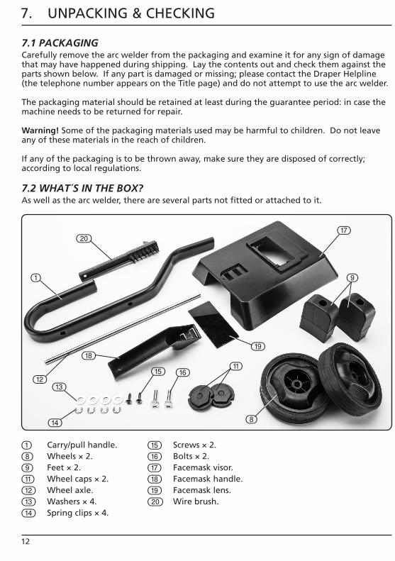
7.1 PACKAGINGCarefully remove the arc welder from the packaging and examine it for any sign of damage that may have happened during shipping. Lay the contents out and check them against the parts shown below. If any part is damaged or missing; please contact the Draper Helpline (the telephone number appears on the Title page) and do not attempt to use the arc welder.
The packaging material should be retained at least during the guarantee period: in case the machine needs to be returned for repair.
Warning! Some of the packaging materials used may be harmful to children. Do not leave any of these materials in the reach of children.
If any of the packaging is to be thrown away, make sure they are disposed of correctly; according to local regulations.
7.2 WHAT´S IN THE BOX?As well as the arc welder, there are several parts not fitted or attached to it.
12
Carry/pull handle. Wheels × 2. Feet × 2. Wheel caps × 2. Wheel axle. Washers × 4. Spring clips × 4.
Screws × 2. Bolts × 2. Facemask visor. Facemask handle. Facemask lens. Wire brush.

8. ASSEMBLING THE ARC WELDER
13
8.1 FITTING THE CARRY/PULL HANDLE– FIG. 1– Place the handle on top of the unit, as
indicated and fasten in place using the 2 bolts supplied.
8.2 FITTING THE WHEELS – FIGS. 2 – 4– Using one end of the wheel axle , clip one of
the 4 spring clips into the outer groove at the end of the axle. Slide on one of the 4 wheel washers over the open end of the axle, followed by one of the wheels (making sure that it is the correct way around as shown). Follow this with a further wheel washer and further spring clip – the first wheel should now be securely on the end of the axle.
– Pass the opposite end of the axle through the hole situated on the outer casing of the machine
, and out through the hole on the opposite side of the unit (fig.3).
– Thread the third spring clip into the inner groove on the other end of the axle followed by the third washer and the remaining wheel.
– Thread on the remaining washer and then fasten the remaining spring clip into the outer groove.
– Snap-fit the 2 wheel caps in place to complete the wheel assembly.
FIG. 1
FIG. 3
FIG. 4
FIG. 2

8. ASSEMBLING THE ARC WELDER
14
8.3 FITTING THE FEET – FIG. 5– Position the feet on the underside of the
machine, as shown in fig.5.– The two feet contain a slot that enables
them to be slid onto the bottom of each of the side panels of the machine.
– Using the 2 screws provided , secure each foot to the underside of the machine base.
8.4 ASSEMBLING THE FACEMASK – FIGS. 6 – 7– Locate the ridges on facemask handle into
the corresponding slots on the facemask visor and gently push-fit in place (fig. 6).
– Fit the facemask lens into the recess situated inside the facemask visor . The lens is held in place by the 2 clips .
FIG. 5
FIG. 6
FIG. 7
9. SETTING THE ARC WELDER
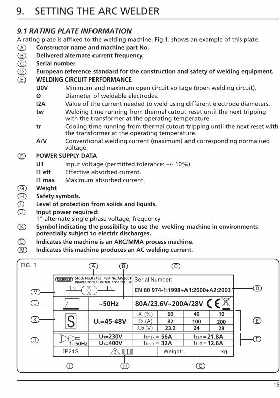
9.1 RATING PLATE INFORMATIONA rating plate is affixed to the welding machine. Fig.1. shows an example of this plate.
Constructor name and machine part No. Delivered alternate current frequency. Serial number European reference standard for the construction and safety of welding equipment. WELDING CIRCUIT PERFORMANCE
U0V Minimum and maximum open circuit voltage (open welding circuit). Ø Diameter of weldable electrodes. I2A Value of the current needed to weld using different electrode diameters. tw Welding time running from thermal cutout reset until the next tripping
with the transformer at the operating temperature. tr Cooling time running from thermal cutout tripping until the next reset with
the transformer at the operating temperature. A/V Conventional welding current (maximum) and corresponding normalised
voltage. POWER SUPPLY DATA
U1 Input voltage (permitted tolerance: +/- 10%) I1 eff Effective absorbed current. I1 max Maximum absorbed current.
Weight Safety symbols.
Level of protection from solids and liquids. Input power required:
1" alternate single phase voltage, frequency Symbol indicating the possibility to use the welding machine in environments
potentially subject to electric discharges. Indicates the machine is an ARC/MMA process machine. Indicates this machine produces an AC welding current.
15
FIG. 1
16
9. SETTING THE ARC WELDER
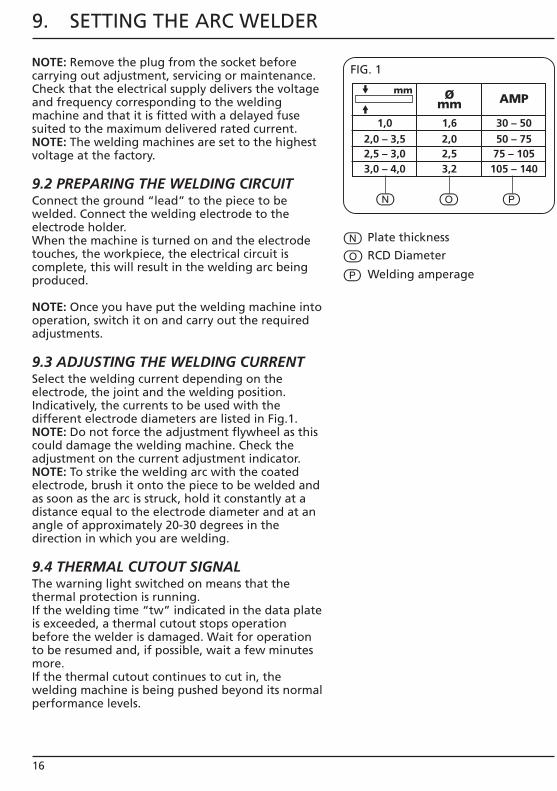
NOTE: Remove the plug from the socket before carrying out adjustment, servicing or maintenance.Check that the electrical supply delivers the voltage and frequency corresponding to the welding machine and that it is fitted with a delayed fuse suited to the maximum delivered rated current.NOTE: The welding machines are set to the highest voltage at the factory.
9.2 PREPARING THE WELDING CIRCUITConnect the ground “lead” to the piece to be welded. Connect the welding electrode to the electrode holder.When the machine is turned on and the electrode touches, the workpiece, the electrical circuit is complete, this will result in the welding arc being produced.
NOTE: Once you have put the welding machine into operation, switch it on and carry out the required adjustments.
9.3 ADJUSTING THE WELDING CURRENTSelect the welding current depending on the electrode, the joint and the welding position.Indicatively, the currents to be used with the different electrode diameters are listed in Fig.1.NOTE: Do not force the adjustment flywheel as this could damage the welding machine. Check the adjustment on the current adjustment indicator.NOTE: To strike the welding arc with the coated electrode, brush it onto the piece to be welded and as soon as the arc is struck, hold it constantly at a distance equal to the electrode diameter and at an angle of approximately 20-30 degrees in the direction in which you are welding.
9.4 THERMAL CUTOUT SIGNALThe warning light switched on means that the thermal protection is running.If the welding time “tw” indicated in the data plate is exceeded, a thermal cutout stops operation before the welder is damaged. Wait for operation to be resumed and, if possible, wait a few minutes more.If the thermal cutout continues to cut in, the welding machine is being pushed beyond its normal performance levels.
FIG. 1
Plate thickness
RCD Diameter
Welding amperage
1,0 1,6 30 – 50
mm Ø mm AMP
2,0 – 3,5 2,0 50 – 75 2,5 – 3,0 2,5 75 – 105 3,0 – 4,0 3,2 105 – 140

9. SETTING THE ARC WELDER
9.5 RECOMMENDATIONS FOR USEOnly use an extension lead when absolutely necessary and providing it has an equal or larger section to the power cable and is fitted with a grounding conductor.Do not block the welder air intakes. Do not store the welder in containers or on shelving that does not guarantee suitable ventilation.Do not use the welder in any environment in the presence of gas, vapours, conductive powders (e.g. iron shavings), brackish air, caustic fumes or other agents that could damage the metal parts and electrical insulation.NOTE: The electric parts of the welder have been treated with protective resins. When used for the first time, smoke may be noticed; this is caused by the resin drying out completely. The smoke should only last for a few minutes.
17

18
10. MAINTENANCE
10.1 MAINTENANCE & PARTS REPLACEMENTRegular inspection and cleaning reduces the necessity for maintenance operations and will keep your welder in good working condition.The welder must be correctly ventilated during tool operation. For this reason avoid blocking the air inlets. After use disconnect the tool from the power supply and vacuum the ventilation slots.
If the replacement of the supply cord is necessary, this has to be done by the manufacturer or his agent in order to avoid a safety hazard.
11. EXPLANATION OF SYMBOLS
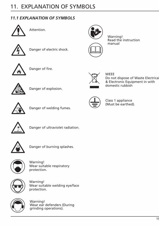
11.1 EXPLANATION OF SYMBOLS
Warning! Wear suitable respiratory protection.
Warning! Wear suitable welding eye/face protection.
Warning! Read the instruction manual
Warning! Wear ear defenders (During grinding operations).
WEEEDo not dispose of Waste Electrical& Electronic Equipment in with domestic rubbish
Class 1 appliance(Must be earthed).
Attention.
Danger of electric shock.
Danger of fire.
Danger of explosion.
Danger of welding fumes.
Danger of ultraviolet radiation.
Danger of burning splashes.
19
20
12. DISPOSAL
12.1 DISPOSAL– At the end of the machine’s working life, or when it can no longer be repaired, ensure
that it is disposed of according to national regulations.– Contact your local authority for details of collection schemes in your area. In all circumstances: • Do not dispose of power tools with domestic waste. • Do not incinerate. • Do not abandon in the environment. • Do not dispose of WEEE* as unsorted municipal waste.
* Waste Electrical & Electronic Equipment.

21
NOTES

22
NOTES

23
NOTES
CONTACTS
- DRAPER TOOLS LIMITED, Hursley Road, Chandler's Ford, Eastleigh, Hampshire. SO53 1YF. U.K.
- Helpline: (023) 8049 4344 - Sales Desk: (023) 8049 4333 - General Enquiries: (023) 8026 6355
- Service/Warranty Repair Agent For aftersales servicing or warranty repairs, please contact the Draper Tools Helpline for details of an agent in your local area.
YOUR DRAPER STOCKIST
KCCH1115
drapertools.com