Customs Invoicing Instructions for Suppliers Shipping to ...
INSTRUCTIONS
Page 1 of 41
Replacement Components Division @ Carrier Corporation 10/99 TA526307 Instruction Sheet.dot
*XX99TA526307* Instruction Sheet Number: 99TA526307 *XX99TA526307* (for RCD use only) Description: 06N COMPRESSOR MOTOR REPLACEMENT
Author: Steve Vonborstel Date: June 11, 2003
Part Number: 1.0 PURPOSE:
To provide a set of instructions for changing a 06N screw compressor motor in the field. This procedure will outline the required “pre-inspection” of the compression end to ensure that a motor change will repair the compressor. It will identify the parts, tools and checks that will be required to ensure the motor is assembled correctly. This procedure also covers gear removal and replacement.
2.0 SCOPE:
This procedure applies to all 06N screw compressor motor failures in the field. 3.0 OVERVIEW:
A failed motor from an 06N compressor can be replaced provided the necessary tools and parts are available. Before this can take place, one must ensure that the motor is the only problem with the compressor. Many electrical failures are the result of a mechanical failure. There are also some electrical failures that cause mechanical damage which cannot be repaired. Several items must be taken into account if a field motor replacement is to be considered:
A. A motor cannot be replaced with the compressor mounted on the unit or chiller. The compressor must be removed.
B. Inspection of the compression end can be performed with the compressor mounted on the unit. C. In most cases the same equipment & rigging used to remove the compressor can be used to remove
and reinstall the motor. D. A “pre-inspection” should be performed to ensure that there is no mechanical damage to the
compression end. Mechanical damage to the compression end cannot be repaired in the field. The o-rings required to perform this inspection are available in RCD kit No. 06NA660027. This will allow the compressor to be reassembled with or without replacing the motor.
E. The stator & cast motor housing must be replaced as an assembly. The stator is pressed into the casting to a specific depth and cannot be pressed out. Because there are different motor suppliers and damage to the motor rotor and bearings may occur, a replacement rotor assembled on the motor shaft with new bearings will be supplied. The kit will contain:
♦ Stator pressed into the motor housing ♦ Motor shaft with rotor & bearings ♦ Motor housing seals, insulator blocks, sensor pins & terminal pin nuts ♦ Terminal pins marked & installed on motor leads
F. A gear puller is required to remove the gears. The requirements for this puller are listed in Appendix I G. An oven that can heat the gears to 320 degrees F (160 degrees C) is required to reinstall the gears on
the tapered shafts. The largest drive gear is ≈12 ½” (320mm) diameter. The gear needs to be heated evenly and the bore must be kept clean, free of oil and dirt. Uneven heating of the gear can damaged the gear and/or lead to improper installation.
Care is required to change a motor especially when the new motor assembly is being inserted into the rotor housing. If this is not done carefully the stator windings can be easily damaged
Page 2 of 41
Instruction Sheet Number: 99TA526307
4.0 PROCEDURES
There are seven separate sections for the procedures including an Appendix listing the required tools:
4.1 ELECTRICAL TEST 4.2 COMPRESSION END INSPECTION 4.3 MOTOR REMOVAL 4.4 MOTOR INSTALLATION 4.5 GEAR INSTALLATION 4.6 DISCHARGE END ASSEMBLY APPENDIX I: REQUIRED TOOL LIST
Page 3 of 41
Instruction Sheet Number: 99TA526307
4.1 ELECTRICAL TESTS
Below is a review of the basic electrical tests which can be performed in the field on the 06N compressor. Do not perform any electrical checks on the compressor until the power has been properly locked out and the electrical and sensor connections to the compressor have been removed.
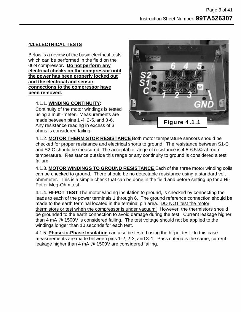
4.1.1. WINDING CONTINUITY: Continuity of the motor windings is tested using a multi-meter. Measurements are made between pins 1 -4, 2-5, and 3-6. Any resistance reading in excess of 3 ohms is considered failing.
4.1.2. MOTOR THERMISTOR RESISTANCE Both motor temperature sensors should be checked for proper resistance and electrical shorts to ground. The resistance between S1-C and S2-C should be measured. The acceptable range of resistance is 4.5-6.5kΩ at room temperature. Resistance outside this range or any continuity to ground is considered a test failure.
4.1.3. MOTOR WINDINGS TO GROUND RESISTANCE Each of the three motor winding coils can be checked to ground. There should be no detectable resistance using a standard volt ohmmeter. This is a simple check that can be done in the field and before setting up for a Hi-Pot or Meg-Ohm test.
4.1.4. HI-POT TEST The motor winding insulation to ground, is checked by connecting the leads to each of the power terminals 1 through 6. The ground reference connection should be made to the earth terminal located in the terminal pin area. DO NOT test the motor thermistors or test when the compressor is under vacuum! However, the thermistors should be grounded to the earth connection to avoid damage during the test. Current leakage higher than 4 mA @ 1500V is considered failing. The test voltage should not be applied to the windings longer than 10 seconds for each test.
4.1.5. Phase-to-Phase Insulation can also be tested using the hi-pot test. In this case measurements are made between pins 1-2, 2-3, and 3 -1. Pass criteria is the same, current leakage higher than 4 mA @ 1500V are considered failing.
Figure 4.1.1

Page 4 of 41
Instruction Sheet Number: 99TA526307
4.1.6. Meg Ohm Test: Another insulation test that that is more readily available in the field is the Meg Ohm Test. Although this is a better test than checking the resistance with an ohm meter, the results can vary significantly depending on the condition of the oil and contamination in the compressor (moisture, acid, particles, etc.). Below are some typically readings for acceptable motors under different conditions using a 500 volt test:
• 50-100 Meg Ohms: A compressor with no refrigerant or oil on the windings.
• 10-20 Meg Ohms: A compressor charge with refrigerant and the windings saturated with oil. No contamination.
• 2-5 Meg Ohms: A compressor charge with refrigerant and windings are saturated with oil that is contaminated with moisture, acids and/or particles
Most failed motors will immediately shown much lower values than are shown above and can be detected with a volt-ohm multi-meter. Testing procedure is the same as shown for the hi-pot test.
Page 5 of 41
Instruction Sheet Number: 99TA526307
4.2 COMPRESSION END INSPECTION
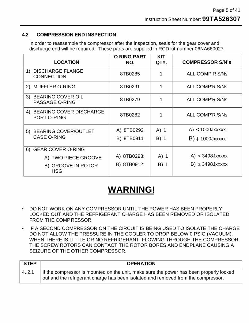
In order to reassemble the compressor after the inspection, seals for the gear cover and discharge end will be required. These parts are supplied in RCD kit number 06NA660027.
LOCATION O-RING PART
NO. KIT
QTY. COMPRESSOR S/N’s
1) DISCHARGE FLANGE CONNECTION 8TB0285 1 ALL COMP’R S/Ns
2) MUFFLER O-RING 8TB0291 1 ALL COMP’R S/Ns
3) BEARING COVER OIL PASSAGE O-RING 8TB0279 1 ALL COMP’R S/Ns
4) BEARING COVER DISCHARGE PORT O-RING 8TB0282 1 ALL COMP’R S/Ns
5) BEARING COVER/OUTLET CASE O-RING
A) 8TB0292
B) 8TB0911
A) 1
B) 1
A) < 1000Jxxxxx
B) ≥ 1000Jxxxxx
6) GEAR COVER O-RING
A) TWO PIECE GROOVE
B) GROOVE IN ROTOR HSG
A) 8TB0293:
B) 8TB0912:
A) 1
B) 1
A) < 3498Jxxxxx
B) ≥ 3498Jxxxxx
WARNING!
• DO NOT WORK ON ANY COMPRESSOR UNTIL THE POWER HAS BEEN PROPERLY LOCKED OUT AND THE REFRIGERANT CHARGE HAS BEEN REMOVED OR ISOLATED FROM THE COMPRESSOR.
• IF A SECOND COMPRESSOR ON THE CIRCUIT IS BEING USED TO ISOLATE THE CHARGE DO NOT ALLOW THE PRESSURE IN THE COOLER TO DROP BELOW 0 PSIG (VACUUM). WHEN THERE IS LITTLE OR NO REFRIGERANT FLOWING THROUGH THE COMPRESSOR, THE SCREW ROTORS CAN CONTACT THE ROTOR BORES AND ENDPLANE CAUSING A SEIZURE OF THE OTHER COMPRESSOR.
STEP OPERATION
4. 2.1 If the compressor is mounted on the unit, make sure the power has been properly locked out and the refrigerant charge has been isolated and removed from the compressor.

Page 6 of 41
Instruction Sheet Number: 99TA526307
4.2.2. Remove the gear cover by removing one bolt on each side and inserting guide pins into the threaded holes. This will prevent the gear cover from dropping when the last bolts are removed. Use a rawhide or dead-blow mallet to knock the gear cover loose. Then slide the cover off the guide pins. The cover weights approximately 50 lbs (23 kgs). Make sure a pan or absorbent pads are placed underneath the cover when it is being removed because oil is usually present.
4.2.3. The motor shaft & screw rotor should rotate smoothly w/o any rough spots. If the compressor does not rotate freely, remove the pinion gear as outlined in section 4.3.4. If the screw rotor shaft does not rotate freely after the gear has been removed there is a problem with the compression end and the compressor will have to be replaced. Note: With the exception of the 06Nxx123xxxx model compressor, both gears will have to be removed when a motor is replaced.
4.2.4. If the compressor is still on the unit, disconnect the discharge line and move it off to the side. Otherwise remove the discharge blank off if present.
4.2.5. The Muffler should be removed next. This will require an E14 Torx socket to remove the eight bolts. An E16 Torx socket sometimes works better on the painted fasteners but care must be taken to ensure the socket does not slip on the fastener. Guide pins can be used after two of the bolts have been removed to hold the muffler in place until all of the fasteners have been removed. A soft- faced hammer may have to be used to knock the muffler free because of the paint.
BOLT HOLES W/GUIDE PINS
BOLT HOLES W/GUIDE PINS
Page 7 of 41
Instruction Sheet Number: 99TA526307
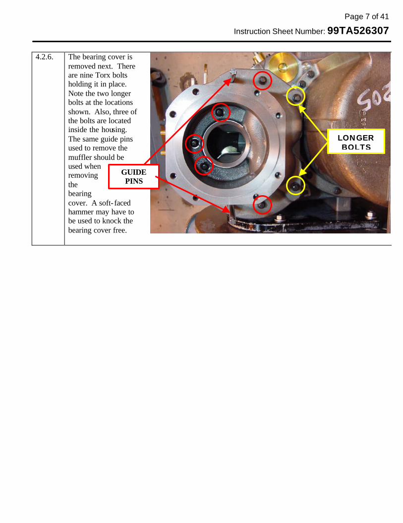
4.2.6. The bearing cover is
removed next. There are nine Torx bolts holding it in place. Note the two longer bolts at the locations shown. Also, three of the bolts are located inside the housing. The same guide pins used to remove the muffler should be used when removing the bearing cover. A soft- faced hammer may have to be used to knock the bearing cover free.
LONGER BOLTS
GUIDE PINS

Page 8 of 41
Instruction Sheet Number: 99TA526307
4.2.7. At this point the outlet case and Taper Roller Bearings (TRBs) for the screw rotors will be exposed.
Do not attempt to removed or disturb the outlet case. There are dowel pins that locate the outlet case to the rotor housing. As long as these two parts are kept together, the screw rotor clearances will be maintained. Do not remove the bolts that retain the TRBs on the screw rotors.
4.2.8. Inspect the TRBs. The rollers ends must have no signs if distress or high axial loads.
DO NOT ATTEMPT TO REMOVE OR DISTURB THE
OUTLET CASE
LOOK IN THROUGH PORT TO SEE THE
DISCHARGE END OF ROTORS
INSPECT TRBs FOR DAMAGE
LOOK FOR DAMAGED ON ROLLER ENDS
LIP ON INNER RACE HAS BEEN
FLARED OUT GOOD ROLLER ENDS

Page 9 of 41
Instruction Sheet Number: 99TA526307
4.2.9. Look in through the discharge port as indicated in 4.2.7. Except for discoloration from carbon and
small amounts of copper, the screw rotors should be free from damage. If there is evidence of screw rotor contact or damage, the compressor will have to be replaced. If the bearings & screws look good, proceed with motor change.
VIEW THROUGH DISCHARGE PORT LOOKING AT SCREW
ROTORS & END PLANE
END FACE OF FEMALE ROTOR,
LIGHT LINES ARE OK
EDGES OF ROTOR FLUTES ARE “ROUGH” & UNEVEN, SCORING ON
ENDS OF ROTOR FLUTES
GOOD SCREW ROTORS & ENPLANE
DAMAGED SCREW ROTORS & ENPLANE
Page 10 of 41
Instruction Sheet Number: 99TA526307
4.3 MOTOR REMOVAL 4.3.1. Make sure the “PRE-INSPECTION” of the compression end is performed before
an attempting to replace the motor. If the compression end is damaged, the compressor will have to be replaced.
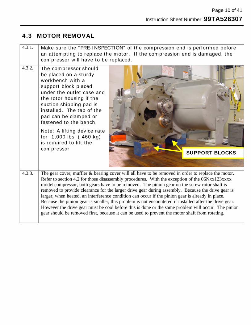
4.3.2. The compressor should be placed on a sturdy workbench with a support block placed under the outlet case and the rotor housing if the suction shipping pad is installed. The tab of the pad can be clamped or fastened to the bench.
Note: A lifting device rate for 1,000 lbs. ( 460 kg) is required to lift the compressor
4.3.3. The gear cover, muffler & bearing cover will all have to be removed in order to replace the motor. Refer to section 4.2 for those disassembly procedures. With the exception of the 06Nxx123xxxx model compressor, both gears have to be removed. The pinion gear on the screw rotor shaft is removed to provide clearance for the larger drive gear during assembly. Because the drive gear is larger, when heated, an interference condition can occur if the pinion gear is already in place. Because the pinion gear is smaller, this problem is not encountered if installed after the drive gear. However the drive gear must be cool before this is done or the same problem will occur. The pinion gear should be removed first, because it can be used to prevent the motor shaft from rotating.
SUPPORT BLOCKS

Page 11 of 41
Instruction Sheet Number: 99TA526307
4.3.4. Install the gear puller on
the pinion gear threading three M12 bolts into the holes in the gear. Gradually tighten the three bolts until the gear pops off. A rag placed between the teeth of the gears can be used to prevent the screw rotor from rotating during this operation. If the drive gear has already been removed, a rage or piece of rope will have to be carefully inserted into the discharge port so it will be pinched in the screw rotors preventing rotation. Use the 3 bolts threaded into the gear to pop the gear free instead of the center bolt if the puller is equipped with one. Striking the center of the puller with a hammer may be required to knock the gear free.
4.3.5. To remove the drive gear, place a folded rag on the bottom of the rotor housing as shown. Set the removed pinion gear on the rag and engage it with the drive gear to prevent it from turning while the puller is being used.
4.3.6. Inspect the bore of the drive gear to make sure that the surface is not galled. If it has been damaged, contact RCD or Carlyle for a replacement gear if required.
Page 12 of 41
Instruction Sheet Number: 99TA526307
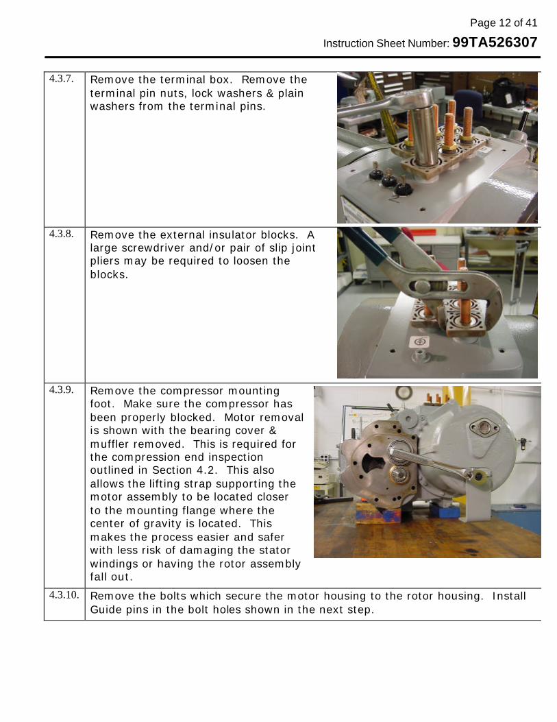
4.3.7. Remove the terminal box. Remove the
terminal pin nuts, lock washers & plain washers from the terminal pins.
4.3.8. Remove the external insulator blocks. A large screwdriver and/or pair of slip joint pliers may be required to loosen the blocks.
4.3.9. Remove the compressor mounting foot. Make sure the compressor has been properly blocked. Motor removal is shown with the bearing cover & muffler removed. This is required for the compression end inspection outlined in Section 4.2. This also allows the lifting strap supporting the motor assembly to be located closer to the mounting flange where the center of gravity is located. This makes the process easier and safer with less risk of damaging the stator windings or having the rotor assembly fall out.
4.3.10. Remove the bolts which secure the motor housing to the rotor housing. Install Guide pins in the bolt holes shown in the next step.

Page 13 of 41
Instruction Sheet Number: 99TA526307
4.3.11. Install one of the long bolts from the bearing cover into one of the bolt holes in
the motor housing for the mounting foot. This can be used as a handle to help hold the motor housing. Pull the motor assembly out about 1-2” (25-50mm) by pulling and “rocking” the motor.
ALL WORK MUST BE PERFORMED ON A SUITABLE WORK SURFACE SO COMPRESSOR AND MOTOR HOUSING CAN NOT FALL, POSSIBLY CAUSING INJURY. BODY PARTS MUST KEPT CLEAR FROM UNDERNEATH THE MOTOR HOUSING
4.3.12. Pull the motor assembly out about 1-2” (25-50mm), and release the tension on the strap or cable. At this point, two of the shorter bolts from the bearing cover can be used with the lifting lugs from the compressor can be placed through bolt holes in the motor housing flange. Terminal pin nuts can be used to hold the bolts in place. This will help prevent the strap from sliding off the housing when the motor is removed.
GUIDE PINS
LIFTING PLATES FROM COMPRESSOR
MOTORHSG BOLT
TERMINAL PIN NUT
GUIDE PINS (ONE HIDDEN)
Page 14 of 41
Instruction Sheet Number: 99TA526307
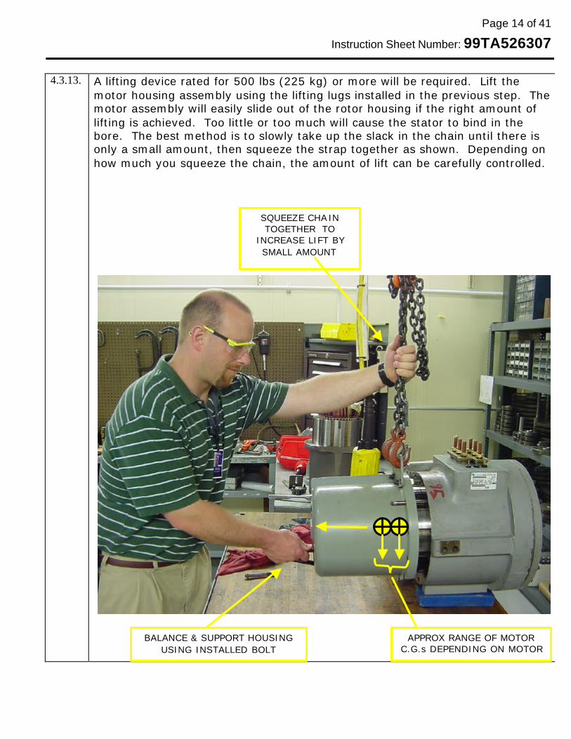
4.3.13. A lifting device rated for 500 lbs (225 kg) or more will be required. Lift the
motor housing assembly using the lifting lugs installed in the previous step. The motor assembly will easily slide out of the rotor housing if the right amount of lifting is achieved. Too little or too much will cause the stator to bind in the bore. The best method is to slowly take up the slack in the chain until there is only a small amount, then squeeze the strap together as shown. Depending on how much you squeeze the chain, the amount of lift can be carefully controlled.
BALANCE & SUPPORT HOUSING USING INSTALLED BOLT
SQUEEZE CHAIN TOGETHER TO
INCREASE LIFT BY SMALL AMOUNT
APPROX RANGE OF MOTOR C.G.s DEPENDING ON MOTOR
Page 15 of 41
Instruction Sheet Number: 99TA526307
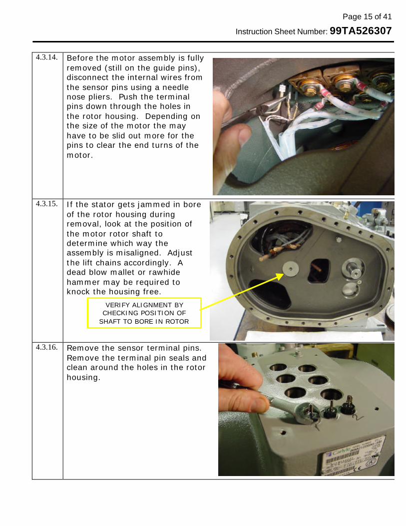
4.3.14. Before the motor assembly is fully
removed (still on the guide pins), disconnect the internal wires from the sensor pins using a needle nose pliers. Push the terminal pins down through the holes in the rotor housing. Depending on the size of the motor the may have to be slid out more for the pins to clear the end turns of the motor.
4.3.15. If the stator gets jammed in bore of the rotor housing during removal, look at the position of the motor rotor shaft to determine which way the assembly is misaligned. Adjust the lift chains accordingly. A dead blow mallet or rawhide hammer may be required to knock the housing free.
4.3.16. Remove the sensor terminal pins. Remove the terminal pin seals and clean around the holes in the rotor housing.
VERIFY ALIGNMENT BY CHECKING POSITION OF
SHAFT TO BORE IN ROTOR
Page 16 of 41
Instruction Sheet Number: 99TA526307
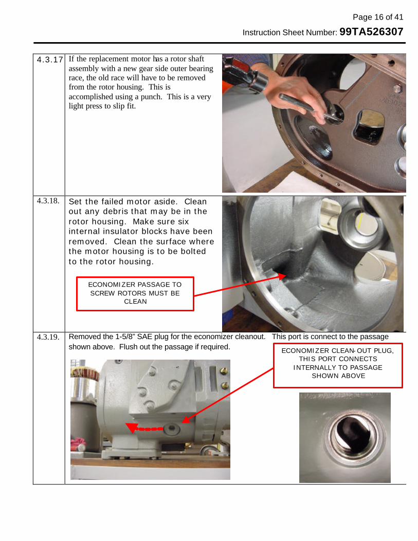
4.3.17. If the replacement motor has a rotor shaft
assembly with a new gear side outer bearing race, the old race will have to be removed from the rotor housing. This is accomplished using a punch. This is a very light press to slip fit.
4.3.18. Set the failed motor aside. Clean out any debris that may be in the rotor housing. Make sure six internal insulator blocks have been removed. Clean the surface where the motor housing is to be bolted to the rotor housing.
4.3.19. Removed the 1-5/8” SAE plug for the economizer cleanout. This port is connect to the passage shown above. Flush out the passage if required.
ECONOMIZER CLEAN-OUT PLUG, THIS PORT CONNECTS
INTERNALLY TO PASSAGE SHOWN ABOVE
ECONOMIZER PASSAGE TO SCREW ROTORS MUST BE
CLEAN
Page 17 of 41
Instruction Sheet Number: 99TA526307
4.4 MOTOR INSTALLATION
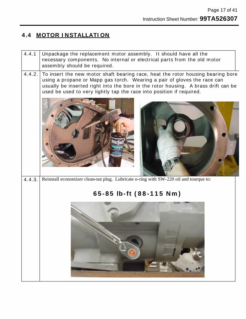
4.4.1 Unpackage the replacement motor assembly. It should have all the necessary components. No internal or electrical parts from the old motor assembly should be required.
4.4.2. To insert the new motor shaft bearing race, heat the rotor housing bearing bore using a propane or Mapp gas torch. Wearing a pair of gloves the race can usually be inserted right into the bore in the rotor housing. A brass drift can be used be used to very lightly tap the race into position if required.
4.4.3. Reinstall economizer clean-out plug. Lubricate o-ring with SW-220 oil and tourque to:
65-85 lb-ft (88-115 Nm)
Page 18 of 41
Instruction Sheet Number: 99TA526307
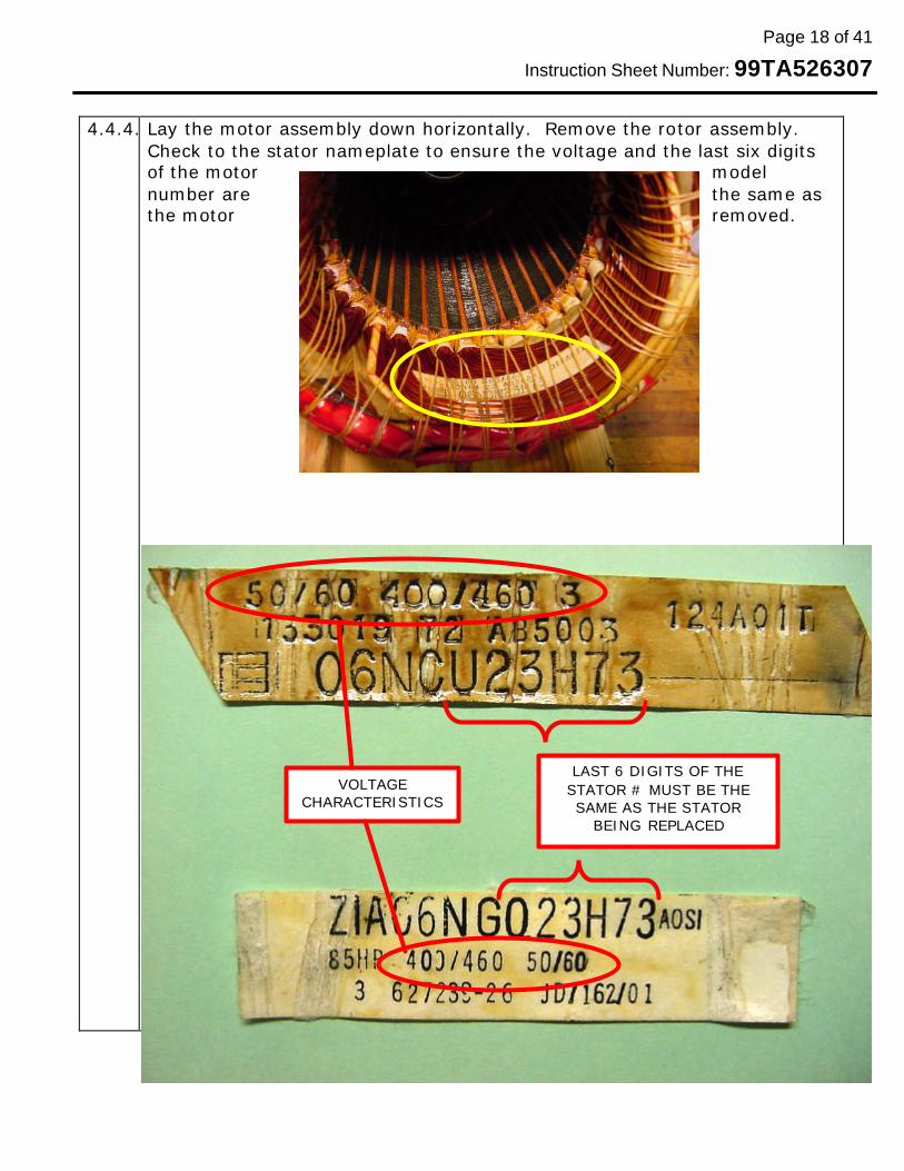
4.4.4. Lay the motor assembly down horizontally. Remove the rotor assembly.
Check to the stator nameplate to ensure the voltage and the last six digits of the motor model number are the same as the motor removed.
LAST 6 DIGITS OF THE STATOR # MUST BE THE SAME AS THE STATOR
BEING REPLACED
VOLTAGE CHARACTERISTICS

Page 19 of 41
Instruction Sheet Number: 99TA526307
4.4.5. Verify that the 1st
seven digits of the replacement rotor part number match the replacement stator part number on the nameplate.
Note:
The 4th digit of the replacement rotor part number may not match rotor of the failed rotor if the manufacture is different
4.4.6. Verify that the outer bearing race is present in the bottom of the motor housing.
OUTER BRG RACE
BACKING RING
SPRING (HIDDEN)

Page 20 of 41
Instruction Sheet Number: 99TA526307
4.4.7. Lubricate both bearings with Castrol SW-220 oil on the motor rotor shaft and reinstall the motor rotor shaft in the motor housing.
4.4.8. Install the new sensor pins for the motor thermistors. Make sure the groove for the o-ring seal is clean. Put a small amount of SW-220 oil on the o-ring and torque the pins to:
10-12 lb-ft (14-16 Nm).
4.4.9. Make sure the o-ring grooves on the motor housing casting are clean and install the two o-rings. A small amount of Castrol SW -220 can be used to lubricate the o-rings.
8TB0283 8TB0286
Page 21 of 41
Instruction Sheet Number: 99TA526307
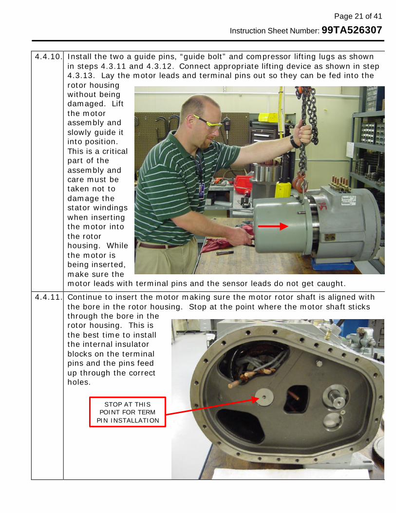
4.4.10. Install the two a guide pins, “guide bolt” and compressor lifting lugs as shown
in steps 4.3.11 and 4.3.12. Connect appropriate lifting device as shown in step 4.3.13. Lay the motor leads and terminal pins out so they can be fed into the rotor housing without being damaged. Lift the motor assembly and slowly guide it into position. This is a critical part of the assembly and care must be taken not to damage the stator windings when inserting the motor into the rotor housing. While the motor is being inserted, make sure the motor leads with terminal pins and the sensor leads do not get caught.
4.4.11. Continue to insert the motor making sure the motor rotor shaft is aligned with the bore in the rotor housing. Stop at the point where the motor shaft sticks through the bore in the rotor housing. This is the best time to install the internal insulator blocks on the terminal pins and the pins feed up through the correct holes.
STOP AT THIS POINT FOR TERM
PIN INSTALLATION
Page 22 of 41
Instruction Sheet Number: 99TA526307
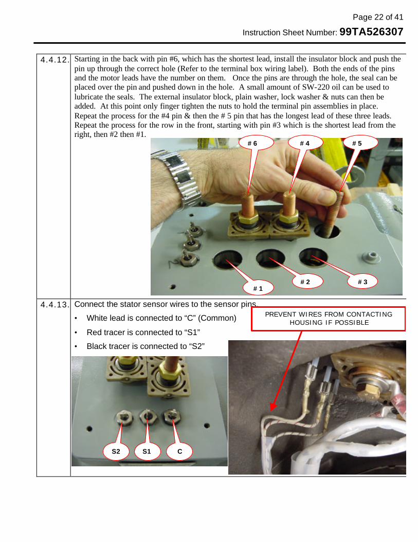
4.4.12. Starting in the back with pin #6, which has the shortest lead, install the insulator block and push the
pin up through the correct hole (Refer to the terminal box wiring label). Both the ends of the pins and the motor leads have the number on them. Once the pins are through the hole, the seal can be placed over the pin and pushed down in the hole. A small amount of SW-220 oil can be used to lubricate the seals. The external insulator block, plain washer, lock washer & nuts can then be added. At this point only finger tighten the nuts to hold the terminal pin assemblies in place. Repeat the process for the #4 pin & then the # 5 pin that has the longest lead of these three leads. Repeat the process for the row in the front, starting with pin #3 which is the shortest lead from the right, then #2 then #1.
4.4.13. Connect the stator sensor wires to the sensor pins.
• White lead is connected to “C” (Common)
• Red tracer is connected to “S1”
• Black tracer is connected to “S2”
#6 #4 #5
#3 #2 #1
C S1 S2
PREVENT WIRES FROM CONTACTING HOUSING IF POSSIBLE
Page 23 of 41
Instruction Sheet Number: 99TA526307
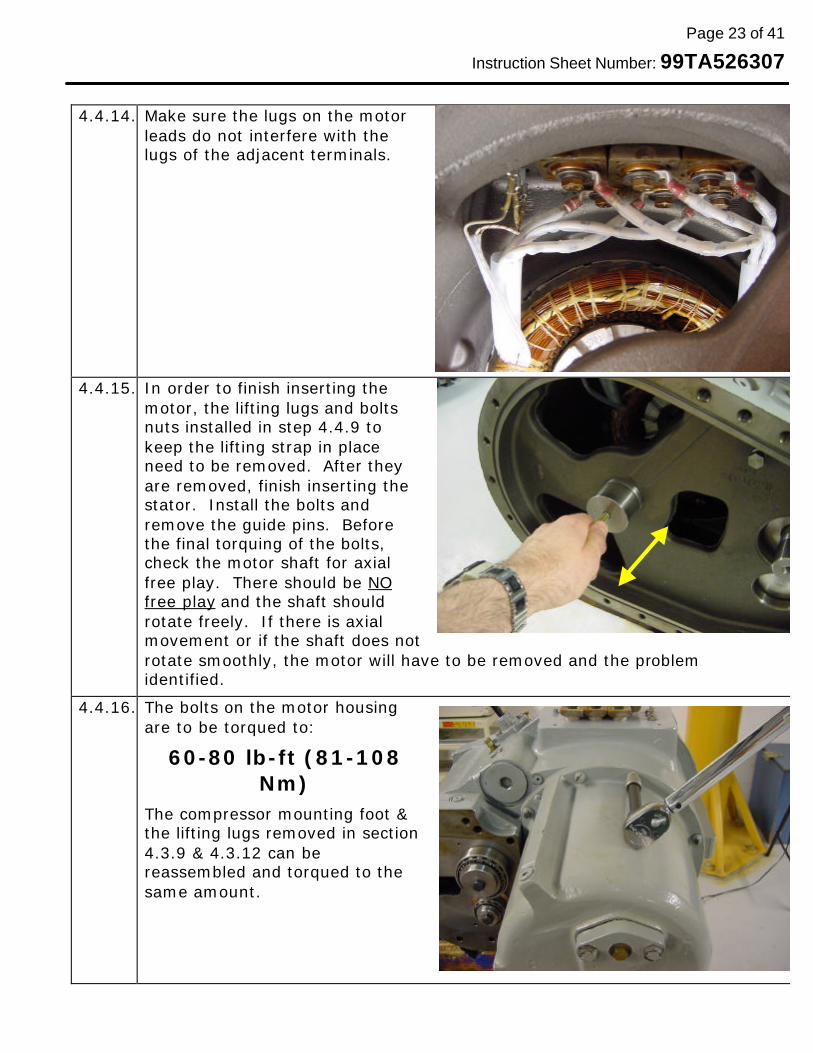
4.4.14. Make sure the lugs on the motor
leads do not interfere with the lugs of the adjacent terminals.
4.4.15. In order to finish inserting the motor, the lifting lugs and bolts nuts installed in step 4.4.9 to keep the lifting strap in place need to be removed. After they are removed, finish inserting the stator. Install the bolts and remove the guide pins. Before the final torquing of the bolts, check the motor shaft for axial free play. There should be NO free play and the shaft should rotate freely. If there is axial movement or if the shaft does not rotate smoothly, the motor will have to be removed and the problem identified.
4.4.16. The bolts on the motor housing are to be torqued to:
60-80 lb-ft (81-108 Nm)
The compressor mounting foot & the lifting lugs removed in section 4.3.9 & 4.3.12 can be reassembled and torqued to the same amount.

Page 24 of 41
Instruction Sheet Number: 99TA526307
4.4.17.The insulator block and terminal pin heights must all be the same. If necessary, pull on the pin with a slight “rocking” motion to get it to the proper height. The top of the insulator blocks should be approximately
¾” ± 1/8” (19mm ± 3mm) above the compressor body.
4.4.18.Torque the terminal pins to:
15-20 lb-ft (20-27 Nm)
Do not over tighten these nuts and make sure to use the new nuts which may be thicker than the ones on the old motor.
4.4.19.Perform the electrical checks outlined in Section 5.1
4.4.20.Proceed to Section 4.5 for the installation of the gears.
Page 25 of 41
Instruction Sheet Number: 99TA526307
4.5 GEAR INSTALLATION:
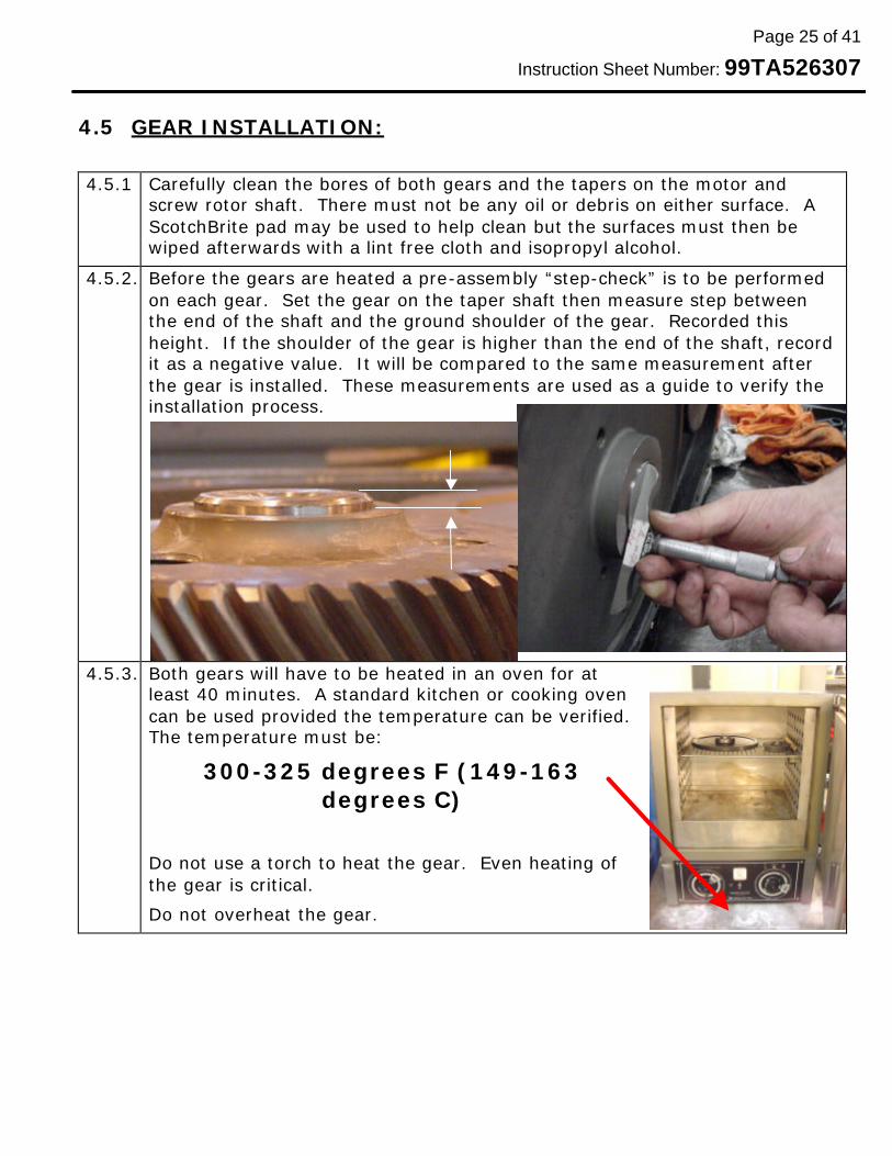
4.5.1 Carefully clean the bores of both gears and the tapers on the motor and screw rotor shaft. There must not be any oil or debris on either surface. A ScotchBrite pad may be used to help clean but the surfaces must then be wiped afterwards with a lint free cloth and isopropyl alcohol.
4.5.2. Before the gears are heated a pre-assembly “step-check” is to be performed on each gear. Set the gear on the taper shaft then measure step between the end of the shaft and the ground shoulder of the gear. Recorded this height. If the shoulder of the gear is higher than the end of the shaft, record it as a negative value. It will be compared to the same measurement after the gear is installed. These measurements are used as a guide to verify the installation process.
4.5.3. Both gears will have to be heated in an oven for at least 40 minutes. A standard kitchen or cooking oven can be used provided the temperature can be verified. The temperature must be:
300-325 degrees F (149-163 degrees C)
Do not use a torch to heat the gear. Even heating of the gear is critical.
Do not overheat the gear.

Page 26 of 41
Instruction Sheet Number: 99TA526307
4.5.4. After the DRIVE gear has been heated
for a minimum of 40 minutes, remove it from the oven using suitable protective gloves and install it on the motor shaft. Hold in place for a couple of seconds to ensure it is seated. Let the gear cool before measuring the step or installing the pinion gear.
4.5.5. After the drive gear has cooled to the point wear it can easily be touched (<130 deg F), repeat the measurement performed in step 4.5.2. Subtract the previous reading recorded for the drive gear in 4.5.2 from the reading taken after the gear was installed. This is the amount of axial interference. The value for the drive gear should be in the range of .060”-.090” (1.5mm – 2.3mm). If the difference is too low there may not be enough axial interference. If the reading is too high, there may be a problem with the parts or the gear was over heated. In either case, the gear should be removed and the process repeated.
4.5.6. Using the same procedure in 4.5.4, install the pinion gear. Be careful that it does not get caught on the drive gear.
4.5.7. Repeat step 4.5.5 for the pinion gear. The difference between the measurements taken in 4.5.2 and the reading after assembly should be .070” - .090” (1.7 –2.3mm).
4.5.8. Verify that the gears rotate smoothly. Backlash between the mating gears should be approximately .003-.008” (0.076-0.203mm).
Page 27 of 41
Instruction Sheet Number: 99TA526307
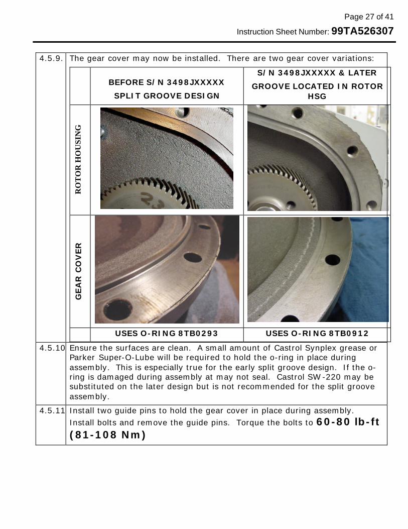
4.5.9. The gear cover may now be installed. There are two gear cover variations:
BEFORE S/N 3498JXXXXX
SPLIT GROOVE DESIGN
S/N 3498JXXXXX & LATER
GROOVE LOCATED IN ROTOR HSG
RO
TO
R H
OU
SIN
G
GEA
R C
OV
ER
USES O-RING 8TB0293 USES O-RING 8TB0912
4.5.10.Ensure the surfaces are clean. A small amount of Castrol Synplex grease or Parker Super-O-Lube will be required to hold the o-ring in place during assembly. This is especially true for the early split groove design. If the o-ring is damaged during assembly at may not seal. Castrol SW -220 may be substituted on the later design but is not recommended for the split groove assembly.
4.5.11.Install two guide pins to hold the gear cover in place during assembly. Install bolts and remove the guide pins. Torque the bolts to 60-80 lb-ft (81-108 Nm)
Page 28 of 41
Instruction Sheet Number: 99TA526307
4.6 COMPRESSION END REASSEMBLY:
Note: RCD seal kit No. 06NA660027 is required for reassembly. (See Section 4.2)
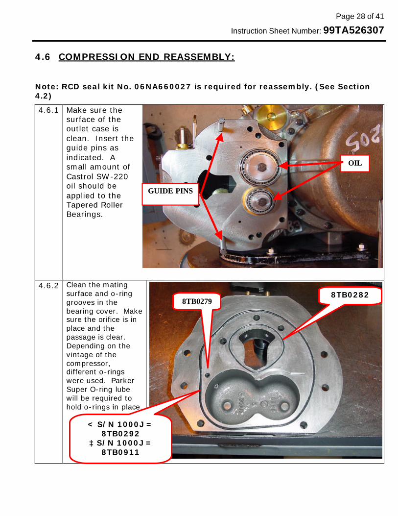
4.6.1 Make sure the surface of the outlet case is clean. Insert the guide pins as indicated. A small amount of Castrol SW-220 oil should be applied to the Tapered Roller Bearings.
4.6.2 Clean the mating surface and o-ring grooves in the bearing cover. Make sure the orifice is in place and the passage is clear. Depending on the vintage of the compressor, different o-rings were used. Parker Super O-ring lube will be required to hold o-rings in place.
OIL
GUIDE PINS
8TB0282 8TB0279
< S/N 1000J = 8TB0292
≥ S/N 1000J = 8TB0911
Page 29 of 41
Instruction Sheet Number: 99TA526307
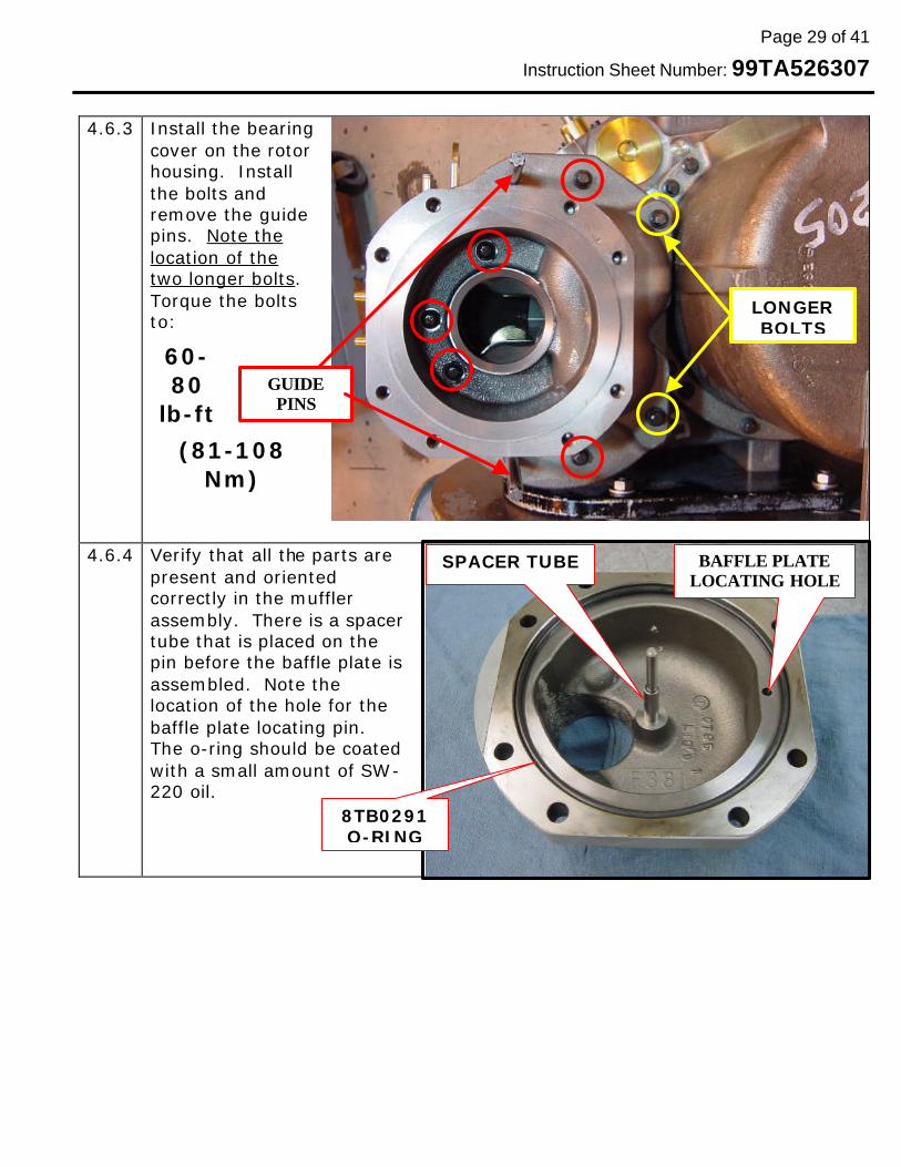
4.6.3 Install the bearing
cover on the rotor housing. Install the bolts and remove the guide pins. Note the location of the two longer bolts. Torque the bolts to:
60-80
lb-ft
(81-108 Nm)
4.6.4 Verify that all the parts are present and oriented correctly in the muffler assembly. There is a spacer tube that is placed on the pin before the baffle plate is assembled. Note the location of the hole for the baffle plate locating pin. The o-ring should be coated with a small amount of SW-220 oil.
LONGER BOLTS
GUIDE PINS
BAFFLE PLATE LOCATING HOLE
8TB0291 O-RING
SPACER TUBE

Page 30 of 41
Instruction Sheet Number: 99TA526307
4.6.5 Install the baffle plate lining
up the locating pin with the hole in the muffler.
4.6.6 Verify that the discharge check valve is fully machined and does not have a cast rib. Compressors produced between s/n’s 4397JXXXXX – 4698JXXXXX may have a cast rib valve which should not be reused. Obtain a compressor discharge check valve & muffler kit (RCD Part No. 06NA660004) if compressor has a cast rib valve.
4.6.7 The valve must also contain a “bumper” in the bottom of the hole. Some early compressors had a white Teflon bumper instead of the Neoprene one shown which is ok. The valves with the Teflon bumper generally do not have a drilled hole in the end.
BAFFLE PLATE LOCATING PIN
NEOPRENE BUMPER SHOWN
NO DRILLED HOLE ON EARLY VALVES W/TEFLON BUMPER
Page 31 of 41
Instruction Sheet Number: 99TA526307
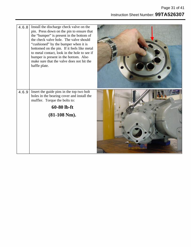
4.6.8 Install the discharge check valve on the
pin. Press down on the pin to ensure that the “bumper” is present in the bottom of the check valve hole. The valve should “cushioned” by the bumper when it is bottomed on the pin. If it feels like metal to metal contact, look in the hole to see if bumper is present in the bottom. Also make sure that the valve does not hit the baffle plate.
4.6.9 Insert the guide pins in the top two bolt holes in the bearing cover and install the muffler. Torque the bolts to:
60-80 lb-ft
(81-108 Nm).
Page 32 of 41
Instruction Sheet Number: 99TA526307
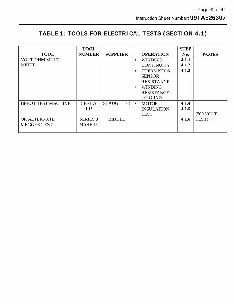
TABLE 1: TOOLS FOR ELECTRICAL TESTS (SECTION 4.1)
TOOL
TOOL NUMBER
SUPPLIER
OPERATION
STEP No.
NOTES
VOLT-OHM MULTI-METER
• WINDING CONTINUITY
• THERMISTOR SENSOR RESISTANCE
• WINDING RESISTANCE TO GRND
4.1.1 4.1.2 4.1.3
HI-POT TEST MACHINE OR ALTERNATE MEGGER TEST
SERIES 103
SERIES 3 MARK III
SLAUGHTER
BIDDLE
• MOTOR INSULATION TEST
4.1.4 4.1.5
4.1.6
(500 VOLT TEST)
Page 33 of 41
Instruction Sheet Number: 99TA526307
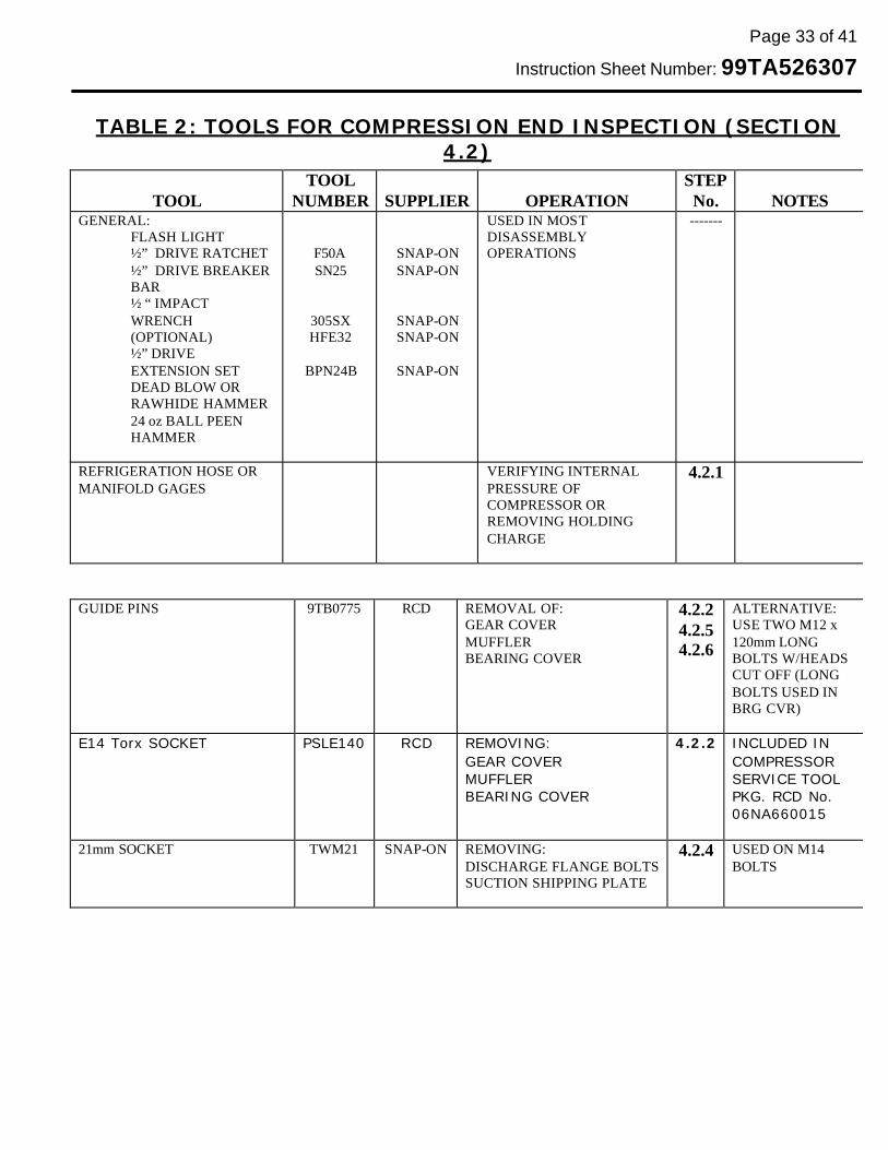
TABLE 2: TOOLS FOR COMPRESSION END INSPECTION (SECTION
4.2)
GUIDE PINS 9TB0775 RCD REMOVAL OF:
GEAR COVER MUFFLER BEARING COVER
4.2.2 4.2.5 4.2.6
ALTERNATIVE: USE TWO M12 x 120mm LONG BOLTS W/HEADS CUT OFF (LONG BOLTS USED IN BRG CVR)
E14 Torx SOCKET PSLE140 RCD REMOVING: GEAR COVER MUFFLER BEARING COVER
4.2.2
INCLUDED IN COMPRESSOR SERVICE TOOL PKG. RCD No. 06NA660015
21mm SOCKET TWM21 SNAP-ON REMOVING: DISCHARGE FLANGE BOLTS SUCTION SHIPPING PLATE
4.2.4 USED ON M14 BOLTS
TOOL
TOOL NUMBER
SUPPLIER
OPERATION
STEP No.
NOTES
GENERAL: FLASH LIGHT ½” DRIVE RATCHET ½” DRIVE BREAKER BAR ½ “ IMPACT WRENCH (OPTIONAL) ½” DRIVE EXTENSION SET DEAD BLOW OR RAWHIDE HAMMER 24 oz BALL PEEN HAMMER
F50A SN25
305SX HFE32
BPN24B
SNAP-ON SNAP-ON
SNAP-ON SNAP-ON
SNAP-ON
USED IN MOST DISASSEMBLY OPERATIONS
-------
REFRIGERATION HOSE OR MANIFOLD GAGES
VERIFYING INTERNAL PRESSURE OF COMPRESSOR OR REMOVING HOLDING CHARGE
4.2.1

Page 34 of 41
Instruction Sheet Number: 99TA526307
TABLE 3: TOOLS FOR MOTOR REMOVAL (SECTION 4.3)
TOOL
TOOL NUMBER
SUPPLIER
OPERATION
STEP No.
NOTES
GENERAL: • WORKBENCH • LIFT (CHAIN FALL,
HOIST) • SUPPORT BLOCKS • 6’ (2m) NYLON LIFTING
STRAP • FLASH LIGHT • ½” DRIVE RATCHET • ½” DRIVE BREAKER BAR • ½ “ IMPACT WRENCH
(OPTIONAL) • ½” DRIVE EXTENSION
SET • DEAD BLOW OR
RAWHIDE HAMMER • 24 oz BALL PEEN
HAMMER
F50A SN25
305SX HFE32
BPN24B
MIDSTATE
SNAP-ON SNAP-ON
SNAP-ON SNAP-ON
SNAP-ON
USED FOR LIFTING COMP’R & MOTOR
ASSEMBLY
USED IN MOST DISASSEMBLY OPERATIONS
------- MUST SAFELY SUPPORT 1000 LBS RATED FOR 1000 LBS (460 kg) OR MORE (2x4 & 4x4)
GEAR PULLER (ENGINE HARMONIC BALANCER PULLER)
4205A PROTO OR
MAKE
GEAR REMOVAL 4.3.4 4.3.5
FIGURE 1A & 1B FOR ALTERNATE (PAGE 11)
E14 Torx SOCKET PSLE140 RCD REMOVING: MOTOR HOUSING MOUNTING FOOT LIFTING LUGS
4.3.9 4.3.10 4.3.11
INCLUDED IN COMPRESSOR SERVICE TOOL PKG. RCD No. 06NA660015

Page 35 of 41
Instruction Sheet Number: 99TA526307
TABLE 3: TOOLS FOR MOTOR REMOVAL (SECTION 4.3) CONTINUED
19mm DEEP WELL SOCKET TSM19 SNAP-ON TERMINAL PIN NUTS
4.3.7
SLIP JOINT PLIERS
#420G CHANNELOCK REMOVE TERMINAL PIN INSULATOR BLOCKS
4.3.8 WATER PUMP PLIERS
GUIDE PINS 9TB0775 RCD REMOVAL OF: MOTOR
4.3.10 ALTERNATIVE: USE TWO M12 x 120mm LONG BOLTS W/HEADS CUT OFF (LONG BOLTS USED IN BRG CVR)
NEEDLE NOSE PLIRES 196ACP SNAP-ON REMOVE SENSOR WIRES FROM SENSOR PINS
4.3.14
9/16” SOCKET OR WRENCH TS181A SNAP-ON REMOVE SENSOR PINS
4.3.16
¾” (19mm) HEX DRIVE SA24E SNAP-ON REMOVE 1-5/8” SAE ECONOMIZER CLEAN-OUT PLUG
4.3.19
PUNCH
PPC110LA SNAP-ON REMOVE GEAR SIDE MOTOR SHAFT TRB OUTER RACE
4.3.17

Page 36 of 41
Instruction Sheet Number: 99TA526307
TABLE 3: TOOLS FOR MOTOR REMOVAL (SECTION 4.3) CONTINUE D PICTURE OF SPECIAL TOOL: DRIVE & PINION GEAR REMOVER
FIGURE 1A FIGURE 1B
3 HOLES ON 2.50” .... B.C. 3 HOLES ON 4.50” .... B.C.
6 CLEARANCE HOLES TOTAL FOR
M12 BOLTS
BOLT NOT REQ’D
1” (25MM) . BOSS
3/8” (10mm) HIGH
1.5” (38MM) THK

Page 37 of 41
Instruction Sheet Number: 99TA526307
TABLE 4: TOOLS FOR MOTOR INSTALATION (SECTION 4.4)
TOOL
TOOL NUMBER
SUPPLIER
OPERATION
STEP No.
NOTES
GENERAL: • WORKBENCH • LIFT (CHAIN FALL,
HOIST) • SUPPORT BLOCKS • 6’ (2m) NYLON LIFTING
STRAP • FLASH LIGHT • ½” DRIVE RATCHET • ½” DRIVE BREAKER BAR • ½ “ IMPACT WRENCH
(OPTIONAL) • ½” DRIVE EXTENSION
SET • DEAD BLOW OR
RAWHIDE HAMMER • 24 oz BALL PEEN
HAMMER
F50A SN25
305SX HFE32
BPN24B
MIDSTATE
SNAP-ON SNAP-ON
SNAP-ON SNAP-ON
SNAP-ON
USED FOR LIFTING COMP’R & MOTOR
ASSEMBLY
USED IN MOST DISASSEMBLY OPERATIONS
------- MUST SAFELY SUPPORT 1000 LBS RATED FOR 1000 LBS (460 kg) OR MORE (2x4 & 4x4)
¾” (19mm) HEX DRIVE SA24E SNAP-ON INSTALLING 1-5/8” SAE ECONOMIZER CLEAN-OUT PLUG
4.4.3
PROPANE OR MAPP GAS TORCH
HEATING BEARING BORE IN ROTOR HOUSING FOR BEARING RACE INSTALLATION
4.4.2

Page 38 of 41
Instruction Sheet Number: 99TA526307
TABLE 4: TOOLS FOR MOTOR INSTALATION (SECTION 4.4) CONTINUED
TOOL TOOL
NUMBER
SUPPLIER
OPERATION STEP No.
NOTES
CASTROL SW-220 OIL
RCD LUBRICATING BEARINGS & O-RINGS DURING INSTALATION
4.4.7 4.4.8 4.4.12
ONLY VERY SMALL AMOUNT IS NEEDED
TORQUE WRENCH (2-20 LB-FT)
74025 S-K SENSOR PIN & TERMINAL PIN INSTALLATION
4.4.8 4.4.18
(3-30 Nm)
9/16” SOCKET TS181A SNAP-ON INSTALL SENSOR PINS
4.4.8
GUIDE PINS 9TB0775 RCD INSTALATION OF: • MOTOR HOUSING
4.4.10
ALTERNATIVE: USE TWO M12 x 120mm LONG BOLTS W/HEADS CUT OFF (LONG BOLTS USED IN BRG CVR)
NEEDLE NOSE PLIERS 196ACP SNAP-ON INSTALL SENSOR WIRES FROM SENSOR PINS
4.4.13
Page 39 of 41
Instruction Sheet Number: 99TA526307
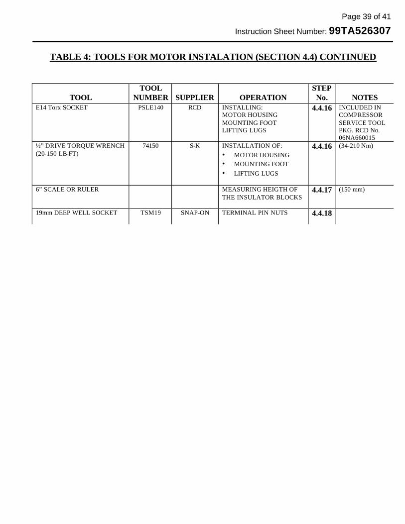
TABLE 4: TOOLS FOR MOTOR INSTALATION (SECTION 4.4) CONTINUED
TOOL
TOOL NUMBER
SUPPLIER
OPERATION
STEP No.
NOTES
E14 Torx SOCKET PSLE140 RCD INSTALLING: MOTOR HOUSING MOUNTING FOOT LIFTING LUGS
4.4.16 INCLUDED IN COMPRESSOR SERVICE TOOL PKG. RCD No. 06NA660015
½” DRIVE TORQUE WRENCH (20-150 LB-FT)
74150 S-K INSTALLATION OF: • MOTOR HOUSING • MOUNTING FOOT • LIFTING LUGS
4.4.16
(34-210 Nm)
6” SCALE OR RULER MEASURING HEIGTH OF THE INSULATOR BLOCKS
4.4.17 (150 mm)
19mm DEEP WELL SOCKET TSM19 SNAP-ON TERMINAL PIN NUTS
4.4.18

Page 40 of 41
Instruction Sheet Number: 99TA526307
TABLE 5: TOOLS FOR GEAR ASSEMBLY (SECTION 4.5)
TOOL
TOOL NUMBER
SUPPLIER
OPERATION
STEP No.
NOTES
OVEN CAPABLE OF 325 DEG F
USED TO HEAT THE GEARS FOR ASSEMBLY
4.5.3 LARGEST GEAR & 12 ½” (320 mm)
0-1” DEPTH MICS
BROWN & SHARP
PERFORMING AXAIL INTERFERENCE MEASUREMENTS
4.5.2 4.5.5 4.5.7
INSULATED GLOVES
HANDLING THE HEATED GEARS
4.5.4 4.5.6
CASTROL SYNPLEX GREASE
06NA680001 RCD INSTALLING GEAR COVER O-RING
4.5.10 COMES IN KIT No. 06NA660027
GUIDE PINS 9TB0775 RCD INSTALLATION OF: • GEAR COVER
4.5.11
ALTERNATIVE: USE TWO M12 x 120mm LONG BOLTS W/HEADS CUT OFF (LONG BOLTS USED IN BRG CVR)
E14 Torx SOCKET PSLE140 RCD INSTALLATION OF: • GEAR COVER
4.5.11 INCLUDED IN COMPRESSOR SERVICE TOOL PKG. RCD No. 06NA660015
½” DRIVE TORQUE WRENCH (20-150 LB-FT)
74150 S-K INSTALLATION OF: • GEAR COVER
4.5.11
(34-210 Nm)
Page 41 of 41
Instruction Sheet Number: 99TA526307
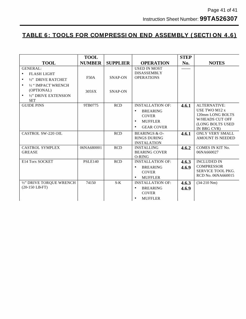
TABLE 6: TOOLS FOR COMPRESSION END ASSEMBLY (SECTION 4.6)
TOOL
TOOL NUMBER
SUPPLIER
OPERATION
STEP No.
NOTES
GENERAL: • FLASH LIGHT • ½” DRIVE RATCHET • ½ “ IMPACT WRENCH
(OPTIONAL) • ½” DRIVE EXTENSION
SET
F50A
305SX
SNAP-ON
SNAP-ON
USED IN MOST DISASSEMBLY OPERATIONS
-------
GUIDE PINS 9TB0775 RCD INSTALLATION OF: • BREARING
COVER • MUFFLER • GEAR COVER
4.6.1
ALTERNATIVE: USE TWO M12 x 120mm LONG BOLTS W/HEADS CUT OFF (LONG BOLTS USED IN BRG CVR)
CASTROL SW-220 OIL
RCD BEARINGS & O-RINGS DURING INSTALATION
4.6.1
ONLY VERY SMALL AMOUNT IS NEEDED
CASTROL SYMPLEX GREASE
06NA680001 RCD INSTALLING BEARING COVER O-RING
4.6.2 COMES IN KIT No. 06NA660027
E14 Torx SOCKET PSLE140 RCD INSTALLATION OF: • BREARING
COVER • MUFFLER
4.6.3 4.6.9
INCLUDED IN COMPRESSOR SERVICE TOOL PKG. RCD No. 06NA660015
½” DRIVE TORQUE WRENCH (20-150 LB-FT)
74150 S-K INSTALLATION OF: • BREARING
COVER • MUFFLER
4.6.3 4.6.9
(34-210 Nm)