Instruction Sheet - deltaww.com This instruction sheet only provides introductory information on...
2
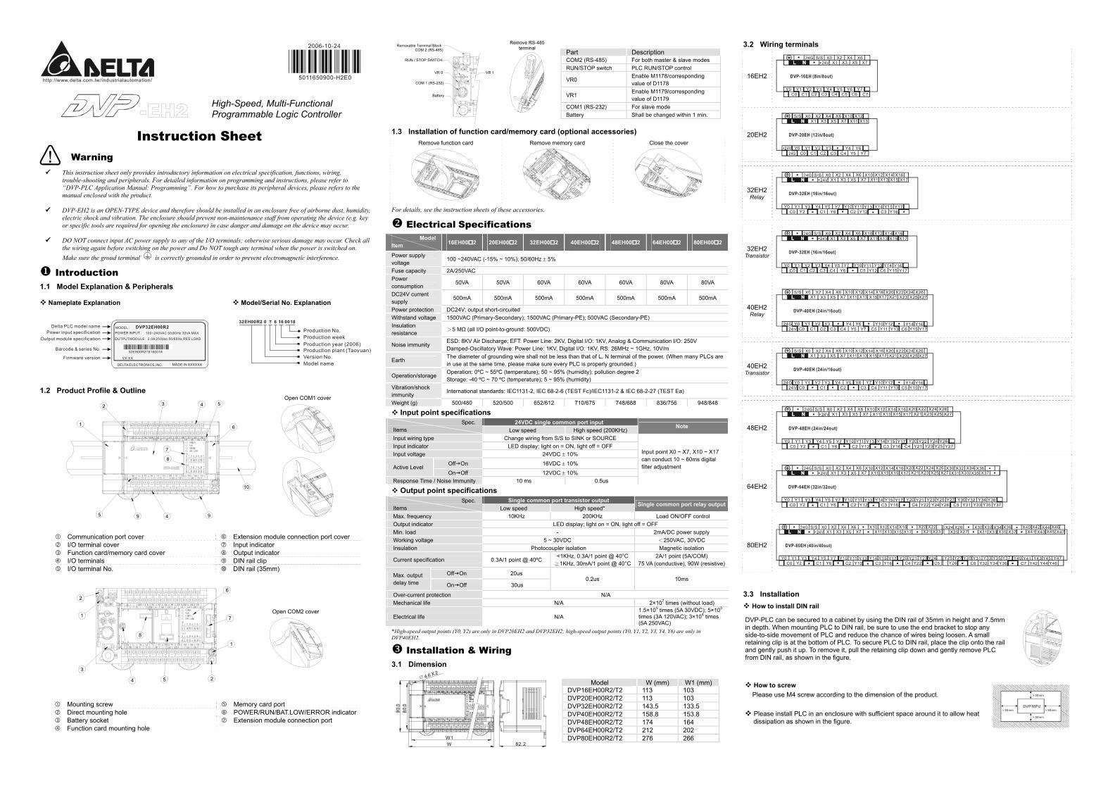
http://www.delta.com.tw/industrialautomation/ 2006-10-24 5011650900-H2E0 High-Speed, Multi-Functional Programmable Logic Controller Instruction Sheet Warning This instruction sheet only provides introductory information on electrical specification, functions, wiring, trouble-shooting and peripherals. For detailed information on programming and instructions, please refer to “DVP-PLC Application Manual: Programming”. For how to purchase its peripheral devices, please refers to the manual enclosed with the product. DVP-EH2 is an OPEN-TYPE device and therefore should be installed in an enclosure free of airborne dust, humidity, electric shock and vibration. The enclosure should prevent non-maintenance staff from operating the device (e.g. key or specific tools are required for opening the enclosure) in case danger and damage on the device may occur. DO NOT connect input AC power supply to any of the I/O terminals; otherwise serious damage may occur. Check all the wiring again before switching on the power and Do NOT tough any terminal when the power is switched on. Make sure the groud terminal is correctly grounded in order to prevent electromagnetic interference. Introduction 1.1 Model Explanation & Peripherals Nameplate Explanation 100~240VAC 50/60Hz 30VA MAX MODEL POWER INPUT OUTPUTMODULE 2.0A 250Vac 50/60Hz RES LOAD 32EH00R2T6160018 VX.XX DELTA ELECTRONICS,INC. MADE IN XXXXXX DVP32EH00R2 Delta PLC model name Power input specification Output module specification Barcode & series No. Firmware version Model/Serial No. Explanation 32EH00R2 0 T 6 16 0018 Model name Version No. Production plant (Taoyuan) Production year (2006) Production week Production No. 1.2 Product Profile & Outline 1 2 3 5 9 4 9 6 10 5 4 7 8 Open COM1 cover Communication port cover Extension module connection port cover I/O terminal cover Input indicator Function card/memory card cover Output indicator I/O terminals DIN rail clip I/O terminal No. DIN rail (35mm) 3 1 2 6 7 1 2 5 4 8 Open COM2 cover Mounting screw Memory card port Direct mounting hole POWER/RUN/BAT.LOW/ERROR indicator Battery socket Extension module connection port Function card mounting hole Removable Terminal Block COM 2 (RS-485) RUN / STOP SWITCH VR 0 VR 1 COM 1 (RS-232) Battery Remove RS-485 terminal Part Description COM2 (RS-485) For both master & slave modes RUN/STOP switch PLC RUN/STOP control VR0 Enable M1178/corresponding value of D1178 VR1 Enable M1179/corresponding value of D1179 COM1 (RS-232) For slave mode Battery Shall be changed within 1 min. 1.3 Installation of function card/memory card (optional accessories) Remove function card Remove memory card Close the cover For details, see the instruction sheets of these accessories. Electrical Specifications Model Item 16EH00 2 20EH00 2 32EH00 2 40EH00 2 48EH00 2 64EH00 2 80EH00 2 Power supply voltage 100 ~240VAC (-15% ~ 10%); 50/60Hz ± 5% Fuse capacity 2A/250VAC Power consumption 50VA 50VA 60VA 60VA 60VA 80VA 80VA DC24V current supply 500mA 500mA 500mA 500mA 500mA 500mA 500mA Power protection DC24V; output short-circuited Withstand voltage 1500VAC (Primary-Secondary); 1500VAC (Primary-PE); 500VAC (Secondary-PE) Insulation resistance >5 MΩ (all I/O point-to-ground: 500VDC) Noise immunity ESD: 8KV Air Discharge; EFT: Power Line: 2KV, Digital I/O: 1KV, Analog & Communication I/O: 250V Damped-Oscillatory Wave: Power Line: 1KV, Digital I/O: 1KV, RS: 26MHz ~ 1GHz, 10V/m Earth The diameter of grounding wire shall not be less than that of L, N terminal of the power. (When many PLCs are in use at the same time, please make sure every PLC is properly grounded.) Operation/storage Operation: 0ºC ~ 55ºC (temperature); 50 ~ 95% (humidity); pollution degree 2 Storage: -40 ºC ~ 70 ºC (temperature); 5 ~ 95% (humidity) Vibration/shock immunity International standards: IEC1131-2, IEC 68-2-6 (TEST Fc)/IEC1131-2 & IEC 68-2-27 (TEST Ea) Weight (g) 500/480 520/500 652/612 710/675 748/688 836/756 948/848 Input point specifications 24VDC single common port input Spec. Items Low speed High speed (200KHz) Note Input wiring type Change wiring from S/S to SINK or SOURCE Input indicator LED display; light on = ON, light off = OFF Input voltage 24VDC ± 10% Off On 16VDC ± 10% Active Level On Off 12VDC ± 10% Response Time / Noise Immunity 10 ms 0.5us Input point X0 ~ X7, X10 ~ X17 can conduct 10 ~ 60ms digital filter adjustment Output point specifications Single common port transistor output Spec. Items Low speed High speed* Single common port relay output Max. frequency 10KHz 200KHz Load ON/OFF control Output indicator LED display; light on = ON, light off = OFF Min. load - 2mA/DC power supply Working voltage 5 ~ 30VDC <250VAC, 30VDC Insulation Photocoupler isolation Magnetic isolation Current specification 0.3A/1 point @ 40ºC <1KHz, 0.3A/1 point @ 40°C ≧1KHz, 30mA/1 point @ 40°C 2A/1 point (5A/COM) 75 VA (conductive), 90W (resistive) Off On 20us Max. output delay time On Off 30us 0.2us 10ms Over-current protection N/A Mechanical life N/A 2×10 times (without load) Electrical life N/A 1.5×10 times (5A 30VDC); 5×10 times (3A 120VAC); 3×10 4 times (5A 250VAC) *High-speed output points (Y0, Y2) are only in DVP20EH2 and DVP32EH2; high-speed output points (Y0, Y1, Y2, Y3, Y4, Y6) are only in DVP40EH2. Installation & Wiring 3.1 Dimension 4 .6 X 2 W W1 80.0 90. 0 82.2 Model W (mm) W1 (mm) DVP16EH00R2/T2 113 103 DVP20EH00R2/T2 113 103 DVP32EH00R2/T2 143.5 133.5 DVP40EH00R2/T2 158.8 153.8 DVP48EH00R2/T2 174 164 DVP64EH00R2/T2 212 202 DVP80EH00R2/T2 276 266 3.2 Wiring terminals 16EH2 X7 X6 X5 X4 X3 X2 X1 X0 Y0 Y1 Y2 Y3 Y4 Y5 Y6 C6 C2 C1 C0 S/S Y7 C3 C4 C5 C7 20EH2 X13 X12 X11 X10 X7 X6 X5 X4 X3 X2 X1 X0 Y0 Y1 C1 Y2 Y3 Y4 C3 C0 S/S C2 C4 +24V 24G Y6 Y5 Y7 32EH2 Relay X17 X16 X15 X14 X13 X12 X11 X10 X7 X6 X5 X4 X3 X2 X1 X0 Y0 Y1 Y2 Y3 Y4 Y5 Y6 C3 C2 C1 C0 Y7 Y12 Y13 Y16 Y17 Y15 Y14 Y11 Y10 S/S 32EH2 Transistor X17 X16 X15 X14 X13 X12 X11 X10 X7 X6 X5 X4 X3 X2 X1 X0 Y0 Y1 C1 Y2 Y3 Y4 Y6 C5 C3 C0 Y5 Y12 Y11 Y17 Y16 Y14 Y13 Y10 Y7 S/S C2 C6 Y15 C4 40EH2 Relay X23 X22 X21 X20 X17 X16 X15 X14 X13 X12 X11 X10 X7 X6 X5 X4 24G Y0 C0 Y2 Y3 C3 C5 C4 C2 24V Y12 Y10 Y6 Y4 S/S Y14 Y16 Y15 C1 Y5 Y11 C6 X24 X26 X25 X27 Y1 Y7 Y13 Y17 X1 40EH2 Transistor X23 X22 X21 X20 X17 X16 X15 X14 X13 X12 X11 X10 X7 X6 X5 X4 24G Y0 C0 Y2 Y3 C4 C2 C1 24V Y12 Y10 Y6 Y4 S/S Y14 Y16 Y15 Y5 Y11 C5 X24 X26 X25 X27 Y1 Y7 Y13 Y17 X1 C3 48EH2 X17 X16 X15 X14 X13 X12 X11 X10 X7 X6 X5 X4 X3 X2 X1 X0 Y0 Y1 Y2 Y3 Y4 Y5 Y6 C3 C2 C1 C0 Y7 Y12 Y13 Y16 Y17 Y15 Y14 Y11 Y10 S/S X27 X26 X25 X24 X23 X22 X21 X20 C4 Y21 Y22 Y27 Y23 Y26 Y24 Y20 Y25 64EH2 X17 X16 X15 X14 X13 X12 X11 X10 X7 X6 X5 X4 X3 X2 X1 X0 Y0 Y1 Y2 Y3 Y4 Y5 Y6 C3 C2 C1 C0 Y7 Y12 Y13 Y16 Y17 Y15 Y14 Y11 Y10 S/S X27 X26 X25 X24 X23 X22 X21 X20 C4 Y22 Y21 Y27 Y24 Y25 Y23 Y20 Y26 X37 X36 X35 X34 X33 X32 X31 X30 C5 Y31 Y32 Y37 Y33 Y36 Y34 Y30 Y35 80EH2 X15 X14 X13 X12 X11 X10 X7 X6 X5 X4 X3 X2 X1 X0 Y0 Y1 Y2 Y3 Y4 Y5 Y6 C3 C2 C1 C0 Y7 Y12 Y13 Y16 Y17 Y15 Y14 Y11 Y10 S/S X23 X22 X21 X20 X17 X16 C4 Y22 Y21 Y27 Y25 Y23 Y20 Y26 X31 X30 X33 X32 X27 X26 X25 X24 C6 Y32 Y31 Y37 Y34 Y35 Y33 Y30 Y36 X35 X34 X37 X36 X41 X40 X43 X42 X45 X44 X47 X46 C5 Y24 C7 Y42 Y41 Y47 Y44 Y45 Y43 Y40 Y46 3.3 Installation How to install DIN rail DVP-PLC can be secured to a cabinet by using the DIN rail of 35mm in height and 7.5mm in depth. When mounting PLC to DIN rail, be sure to use the end bracket to stop any side-to-side movement of PLC and reduce the chance of wires being loosen. A small retaining clip is at the bottom of PLC. To secure PLC to DIN rail, place the clip onto the rail and gently push it up. To remove it, pull the retaining clip down and gently remove PLC from DIN rail, as shown in the figure. How to screw Please use M4 screw according to the dimension of the product. Please install PLC in an enclosure with sufficient space around it to allow heat dissipation as shown in the figure. DVP MPU > 50mm > 50mm > 50mm > 50mm
Transcript of Instruction Sheet - deltaww.com This instruction sheet only provides introductory information on...
http://www.delta.com.tw/industrialautomation/
2006-10-24
5011650900-H2E0
High-Speed, Multi-Functional Programmable Logic Controller
Instruction Sheet
Warning This instruction sheet only provides introductory information on electrical specification, functions, wiring,
trouble-shooting and peripherals. For detailed information on programming and instructions, please refer to “DVP-PLC Application Manual: Programming”. For how to purchase its peripheral devices, please refers to the manual enclosed with the product.
DVP-EH2 is an OPEN-TYPE device and therefore should be installed in an enclosure free of airborne dust, humidity,
electric shock and vibration. The enclosure should prevent non-maintenance staff from operating the device (e.g. key or specific tools are required for opening the enclosure) in case danger and damage on the device may occur.
DO NOT connect input AC power supply to any of the I/O terminals; otherwise serious damage may occur. Check all
the wiring again before switching on the power and Do NOT tough any terminal when the power is switched on. Make sure the groud terminal is correctly grounded in order to prevent electromagnetic interference.
Introduction 1.1 Model Explanation & Peripherals
Nameplate Explanation
100~240VAC 50/60Hz 30VA MAX
MODELPOWER INPUT
OUTPUTMODULE 2.0A 250Vac 50/60Hz RES LOAD
32EH00R2T6160018
VX.XX
DELTA ELECTRONICS,INC. MADE IN XXXXXX
DVP32EH00R2Delta PLC model namePower input specification
Output module specification
Barcode & series No.
Firmware version
Model/Serial No. Explanation
32EH00R2 0 T 6 16 0018
Model nameVersion No.Production plant (Taoyuan)Production year (2006)Production weekProduction No.
1.2 Product Profile & Outline
1
2 3
5 9 4 9
6
10
54
7
8
Open COM1 cover
Communication port cover Extension module connection port cover I/O terminal cover Input indicator Function card/memory card cover Output indicator I/O terminals DIN rail clip I/O terminal No. DIN rail (35mm)
3
1
26
7
1
254
8
Open COM2 cover
Mounting screw Memory card port Direct mounting hole POWER/RUN/BAT.LOW/ERROR indicator Battery socket Extension module connection port Function card mounting hole
Removable Terminal BlockCOM 2 (RS-485)
RUN / STOP SWITCH
VR 0 VR 1
COM 1 (RS-232)
Battery
Remove RS-485 terminal
Part Description COM2 (RS-485) For both master & slave modes RUN/STOP switch PLC RUN/STOP control
VR0 Enable M1178/corresponding value of D1178
VR1 Enable M1179/corresponding value of D1179
COM1 (RS-232) For slave mode Battery Shall be changed within 1 min.
1.3 Installation of function card/memory card (optional accessories) Remove function card
Remove memory card
Close the cover
For details, see the instruction sheets of these accessories.
Electrical Specifications Model Item 16EH00 2 20EH00 2 32EH00 2 40EH00 2 48EH00 2 64EH00 2 80EH00 2
Power supply voltage
100 ~240VAC (-15% ~ 10%); 50/60Hz ± 5%
Fuse capacity 2A/250VAC Power consumption
50VA 50VA 60VA 60VA 60VA 80VA 80VA
DC24V current supply
500mA 500mA 500mA 500mA 500mA 500mA 500mA
Power protection DC24V; output short-circuited Withstand voltage 1500VAC (Primary-Secondary); 1500VAC (Primary-PE); 500VAC (Secondary-PE) Insulation resistance
>5 MΩ (all I/O point-to-ground: 500VDC)
Noise immunity ESD: 8KV Air Discharge; EFT: Power Line: 2KV, Digital I/O: 1KV, Analog & Communication I/O: 250V Damped-Oscillatory Wave: Power Line: 1KV, Digital I/O: 1KV, RS: 26MHz ~ 1GHz, 10V/m
Earth The diameter of grounding wire shall not be less than that of L, N terminal of the power. (When many PLCs are in use at the same time, please make sure every PLC is properly grounded.)
Operation/storage Operation: 0ºC ~ 55ºC (temperature); 50 ~ 95% (humidity); pollution degree 2 Storage: -40 ºC ~ 70 ºC (temperature); 5 ~ 95% (humidity)
Vibration/shock immunity
International standards: IEC1131-2, IEC 68-2-6 (TEST Fc)/IEC1131-2 & IEC 68-2-27 (TEST Ea)
Weight (g) 500/480 520/500 652/612 710/675 748/688 836/756 948/848
Input point specifications 24VDC single common port input Spec.
Items Low speed High speed (200KHz) Note
Input wiring type Change wiring from S/S to SINK or SOURCE Input indicator LED display; light on = ON, light off = OFF Input voltage 24VDC ± 10%
Off On 16VDC ± 10% Active Level
On Off 12VDC ± 10% Response Time / Noise Immunity 10 ms 0.5us
Input point X0 ~ X7, X10 ~ X17 can conduct 10 ~ 60ms digital filter adjustment
Output point specifications Single common port transistor output Spec.
Items Low speed High speed* Single common port relay output
Max. frequency 10KHz 200KHz Load ON/OFF control Output indicator LED display; light on = ON, light off = OFF Min. load - 2mA/DC power supply Working voltage 5 ~ 30VDC <250VAC, 30VDC Insulation Photocoupler isolation Magnetic isolation
Current specification 0.3A/1 point @ 40ºC <1KHz, 0.3A/1 point @ 40°C ≧1KHz, 30mA/1 point @ 40°C
2A/1 point (5A/COM) 75 VA (conductive), 90W (resistive)
Off On 20us Max. output delay time On Off 30us
0.2us 10ms
Over-current protection N/A Mechanical life N/A 2×10⁷ times (without load)
Electrical life N/A 1.5×105 times (5A 30VDC); 5×105 times (3A 120VAC); 3×104 times (5A 250VAC)
*High-speed output points (Y0, Y2) are only in DVP20EH2 and DVP32EH2; high-speed output points (Y0, Y1, Y2, Y3, Y4, Y6) are only in DVP40EH2.
Installation & Wiring 3.1 Dimension
4.6 X 2
WW1
80.0
90.0
82.2
Model W (mm) W1 (mm)
DVP16EH00R2/T2 113 103 DVP20EH00R2/T2 113 103 DVP32EH00R2/T2 143.5 133.5 DVP40EH00R2/T2 158.8 153.8 DVP48EH00R2/T2 174 164 DVP64EH00R2/T2 212 202 DVP80EH00R2/T2 276 266
3.2 Wiring terminals
16EH2
X7X6
X5X4
X3X2
X1X0
Y0 Y1 Y2 Y3 Y4 Y5 Y6C6C2C1C0
S/S
Y7C3 C4 C5 C7
20EH2
X13X12
X11X10
X7X6
X5X4
X3X2
X1X0
Y0 Y1C1
Y2 Y3 Y4C3C0
S/S
C2 C4+24V
24GY6
Y5 Y7
32EH2 Relay
X17X16
X15X14
X13X12
X11X10
X7X6
X5X4
X3X2
X1X0
Y0 Y1Y2
Y3 Y4 Y5Y6 C3C2C1C0
Y7Y12
Y13Y16
Y17Y15Y14Y11Y10
S/S
32EH2 Transistor
X17X16
X15X14
X13X12
X11X10
X7X6
X5X4
X3X2
X1X0
Y0 Y1C1
Y2 Y3 Y4Y6 C5C3C0
Y5Y12
Y11Y17
Y16Y14Y13Y10Y7
S/S
C2 C6 Y15C4
40EH2 Relay
X23X22
X21X20
X17X16
X15X14
X13X12
X11X10
X7X6
X5X4
24G Y0C0
Y2 Y3C3 C5C4C224V
Y12Y10Y6Y4
S/S
Y14 Y16Y15C1 Y5 Y11 C6
X24 X26X25 X27
Y1Y7 Y13 Y17
X1
40EH2 Transistor
X23X22
X21X20
X17X16
X15X14
X13X12
X11X10
X7X6
X5X4
24G Y0C0
Y2 Y3C4C2C124V
Y12Y10Y6Y4
S/S
Y14 Y16Y15
Y5Y11 C5
X24 X26X25 X27
Y1 Y7Y13 Y17
X1
C3
48EH2
X17X16
X15X14
X13X12
X11X10
X7X6
X5X4
X3X2
X1X0
Y0 Y1Y2
Y3 Y4 Y5Y6 C3C2C1C0
Y7Y12
Y13Y16
Y17Y15Y14Y11Y10
S/SX27
X26X25
X24X23
X22X21
X20
C4 Y21Y22
Y27Y23Y26Y24Y20
Y25
64EH2
X17X16
X15X14
X13X12
X11X10
X7X6
X5X4
X3X2
X1X0
Y0 Y1Y2
Y3 Y4 Y5Y6 C3C2C1C0
Y7Y12
Y13Y16
Y17Y15Y14Y11Y10
S/SX27
X26X25
X24X23
X22X21
X20
C4 Y22Y21 Y27
Y24Y25Y23Y20
Y26
X37X36
X35X34
X33X32
X31X30
C5 Y31Y32
Y37Y33Y36Y34Y30
Y35
80EH2
X15X14
X13X12
X11X10
X7X6
X5X4
X3X2
X1X0
Y0 Y1Y2
Y3 Y4 Y5Y6 C3C2C1C0
Y7Y12
Y13Y16
Y17Y15Y14Y11Y10
S/SX23
X22X21
X20X17
X16
C4 Y22Y21 Y27Y25Y23Y20
Y26
X31X30
X33X32
X27X26
X25X24
C6 Y32Y31 Y37
Y34Y35Y33Y30
Y36
X35X34
X37X36
X41X40
X43X42
X45X44
X47X46
C5Y24
C7 Y42Y41 Y47
Y44Y45Y43Y40
Y46
3.3 Installation
How to install DIN rail
DVP-PLC can be secured to a cabinet by using the DIN rail of 35mm in height and 7.5mm in depth. When mounting PLC to DIN rail, be sure to use the end bracket to stop any side-to-side movement of PLC and reduce the chance of wires being loosen. A small retaining clip is at the bottom of PLC. To secure PLC to DIN rail, place the clip onto the rail and gently push it up. To remove it, pull the retaining clip down and gently remove PLC from DIN rail, as shown in the figure.
How to screw Please use M4 screw according to the dimension of the product. Please install PLC in an enclosure with sufficient space around it to allow heat dissipation as shown in the figure.
DVP MPU> 50mm> 50mm
> 50mm
> 50mm
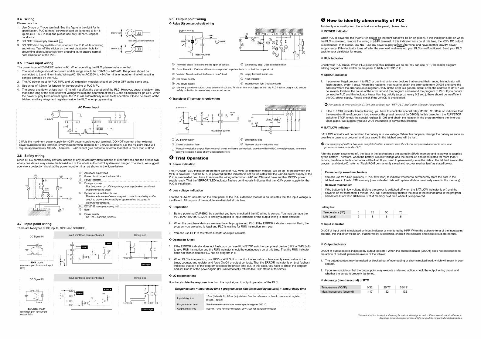
3.4 Wiring Please note that: 1. Use O-type or Y-type terminal. See the figure in the right for its
specification. PLC terminal screws should be tightened to 5 ~ 8 kg-cm (4.3 ~ 6.9 in-Ibs) and please use only 60/75 ºC copper conductor.
2. DO NOT wire empty terminal • 3. DO NOT drop tiny metallic conductor into the PLC while screwing
and wiring. Tear off the sticker on the heat dissipation hole for preventing alien substances from dropping in, to ensure normal heat dissipation of the PLC.
To suit M3.5 screw terminals
Below 6.2
Below 6.2
3.5 Power input wiring The power input of DVP-EH2 series is AC. When operating the PLC, please make sure that: 1. The input voltage should be current and its range should be 100VAC ~ 240VAC. The power should be
connected to L and N terminals. Wiring AC110V or AC220V to +24V terminal or input terminal will result in serious damage on the PLC.
2. The AC power input for PLC MPU and I/O extension modules should be ON or OFF at the same time. 3. Use wires of 1.6mm (or longer) for the grounding of PLC MPU. 4. The power shutdown of less than 10 ms will not affect the operation of the PLC. However, power shutdown time
that is too long or the drop of power voltage will stop the operation of the PLC and all outputs will go OFF. When the power supply turns normal again, the PLC will automatically return to its operation. Please be aware of the latched auxiliary relays and registers inside the PLC when programming.
AC Power Input
L N
2.0 ADC/DC +5V
+24V 24G S/S X0 X1 X2
100~240VAC
0.5A is the maximum power supply for +24V power supply output terminal. DO NOT connect other external power supplies to this terminal. Every input terminal requires 6 ~ 7mA to be driven; e.g. the 16-point input will require approximately 100mA. Therefore, +24V cannot give output to extermal load that is more than 400mA.
3.6 Safety wiring Since a PLC controls many devices, actions of any device may affect actions of other devices and the breakdown of any one device may cause the breakdown of the whole auto-control system and danger. Therefore, we suggest you wire a protection circuit at the power input terminal, as shown in the figure below.
AC power supply load Power circuit protection fuse (3A) Power indicator Emergency stop
This button can cut off the system power supply when accidental emergency takes place.
System circuit isolation device The device is made of electromagnetic contactor and relay as the switch to prevent the instability of system when the power is intermittently supplied.
DVP-PLC (main processing unit) Earth
MC MC
NL
1
1
2
3
4
5
6
7
8
GuardLimit
MC
Power supply AC: 100 ~ 240VAC, 50/60Hz
3.7 Input point wiring There are two types of DC inputs, SINK and SOURCE.
Input point loop equivalent circuit Wiring loop DC Signal IN
S/S
X0
Sinking
SINK mode
(common port for current input S/S)
24VDC24G
X0
S/S
+24VSINK
+5V
24G S/S X0 X1 X2+24V
Sink Type
Input point loop equivalent circuit Wiring loop DC Signal IN
S/S
X0
Sourcing
SOURCE mode (common port for current output S/S)
24VDC24G
X0
S/S
+24V SOURCE
+5V
24G S/S X0 X1 X2+24V
Source Type
3.8 Output point wiring Relay (R) contact circuit wiring
Y0RYLED
C0
LOAD
POWER
DVP-**-**-**-R
RELAY OUTPUT
2
31
5C0 Y0 Y1 C1 Y3 Y4 C2 Y6 Y7
4
MC1 MC2
7
10
3
2
8
9
6
Flywheel diode: To extend the life span of contact Emergency stop: Uses external switch
Fuse: Uses 5 ~ 10A fuse at the common port of output contacts to protect the output circuit.
Varistor: To reduce the interference on AC load Empty terminal: not in use
DC power supply Neon indicator
AC power supply Incandescent light (resistive load)
Manually exclusive output: Uses external circuit and forms an interlock, together with the PLC internal program, to ensure safety protection in case of any unexpected errors.
Transistor (T) contact circuit wiring
Y0LED
C0
TRANSISTOR OUTPUT
LOAD
DVP-**-**-**-T
< 0.5A
MC1 MC2
2
3
1
C0 Y0 Y1 C1 Y4 Y5 Y6 Y75
4
5
3
4
DC power supply Emergency stop
Circuit protection fuse Flywheel diode + inductive load
Manually exclusive output: Uses external circuit and forms an interlock, together with the PLC internal program, to ensure safety protection in case of any unexpected errors.
Trial Operation Power indication
The “POWER” LED indicator on the front panel of PLC MPU (or extension module) will be on (in green) when the MPU is powered. That the MPU is powered but the indicator is not on indicates that the 24VDC power supply of the PLC is overloaded. You have to remove the wiring at terminal +24V and 24G and have another DC24V power supply ready. That the “ERROR” LED indicator flashes continuously indicates that the +24V power supply for the PLC is insufficient.
Low voltage indication That the “LOW.V” indicator on the front panel of the PLC extension module is on indicates that the input voltage is insufficient. All outputs of the module are disabled at this time.
Preparation 1. Before powering DVP-EH2, be sure that you have checked if the I/O wiring is correct. You may damage the
PLC if AC110V or AC220V is directly supplied to input terminals or the output wiring is short-circuited. 2. When the peripheral devices are used to write program into PLC: If the ERROR indicator does not flash, the
program you are using is legal and PLC is waiting for RUN instruction from you. 3. You can use HPP to test “force On/Off” of output contacts.
Operation & test
1. If the ERROR indicator does not flash, you can use RUN/STOP switch or peripheral device (HPP or WPLSoft) to give RUN instruction and the RUN indicator should be continuously on at this time. That the RUN indicator does not flash indicates PLC has no program in it.
2. When PLC is in operation, use HPP or WPLSoft to monitor the set value or temporarily saved value in the
timer, counter, and register and force On/Off of output contacts. That the ERROR indicator is on (not flashes) indicates that part of the program exceeds the preset time-out. In this case, you have to check the program and set On/Off of the power again (PLC automatically returns to STOP status at this time).
I/O response time
How to calculate the response time from the input signal to output operation of the PLC:
Response time = input delay time + program scan time (executed by the user) + output delay time
Input delay time 10ms (default); 0 ~ 60ms (adjustable). See the reference on how to use special register
D1020 ~ D1021.
Program scan time See the reference on how to use special register D1010.
Output delay time Approx. 10ms for relay modules, 20 ~ 30us for transistor modules
How to identify abnormality of PLC To identify abnormality from the indicators on the panel, please check:
POWER indicator When PLC is powered, the POWER indicator on the front panel will be on (in green). If this indicator is not on when the PLC is powered, remove the wiring of +24V terminal. If this indicator turns on at this time, the +24V DC output is overloaded. In this case, DO NOT use DC power supply at +24V terminal and have another DC24V power supply ready. If this indicator turns off after the overload is eliminated, your PLC is malfunctioned. Send your PLC back to your distributor for repair.
RUN indicator Check your PLC status. When PLC is running, this indicator will be on. You can use HPP, the ladder diagram editing program or the switch on the panel to RUN or STOP PLC.
ERROR indicator 1. If you enter illegal program into PLC or use instructions or devices that exceed their range, this indicator will
flash (approx. every 1 sec.). When this happens, you have to obtain the error code from D1004 and save the address where the error occurs in register D1137 (if the error is a general circuit error, the address of D1137 will be invalid). Find out the cause of the error, amend the program and resend the program to PLC. If you cannot connect to PLC and this indicator keeps flashing quickly (approx. every 0.2 sec.), there should be insufficient 24VDC power supply. Please check if the 24VCD is overloaded.
For details of error codes (in D1004, hex coding), see “DVP-PLC Application Manual: Programming”
2. If the ERROR indicator keeps flashing, you have to check the special relay M1008. M1008 is on indicates that
the execution time of program loop exceeds the preset time-out (in D1000). In this case, turn the RUN/STOP switch to STOP, check the special register D1008 and obtain the location in the program where the time-out takes place. We suggest you use WDT instruction to correct this problem.
BAT.LOW indicator
BAT.LOW indicator will be on when the battery is in low voltage. When this happens, change the battery as soon as possible in case your program and data saved in the latched area will be lost.
The changing of battery has to be completed within 1 minute when the PLC is not powered in order to save your procedures and data in the PLC.
After the power is switched off, the data in the latched area are stored in SRAM memory and its power is supplied by the battery. Therefore, when the battery is in low voltage and the power-off has been lasted for more than 1 minute, the data in the latched area will be lost. If you need to permanently save the data in the latched area in the program and device D, refer to “Flash ROM permanently saved and recover mechanism” as stated below.
Permanently saved mechanism You can use WPLSoft (Options -> PLC<=>Flash) to indicate whether to permanently store the data in the latched area in Flash ROM memory (new indicated data will replace all data previously saved in the memory). Recover mechanism If the battery is in low voltage (before the power is switched off when the BAT.LOW indicator is on) and the power is off for more than 1 minute, PLC will automatically restore the data in the latched area in the program and device D of Flash ROM into SRAM memory next time when it is re-powered.
Battery life:
Temperature (ºC) 0 25 50 70 Life (year) 9 8 6 5
Input indicator
On/Off of input point is indicated by input indicator or monitored by HPP. When the action criteria of the input point are true, this indicator will be on. If abnormality is identified, check if the indicator and input circuit are normal.
Output indicator On/Off of output point is indicated by output indicator. When the output indicator (On/Off) does not correspond to the action of its load, please be aware of the follows: 1. The output contact may be melted or blocked out of overloading or short-circuited load, which will result in poor
contact. 2. If you are suspicious that the output point may execute undesired action, check the output wiring circuit and
whether the screw is properly tightened.
Accuracy (month/second) of RTC Temperature (ºC/ºF) 0/32 25/77 55/131 Max. inaccuracy (second) -117 52 -132
The content of this instruction sheet may be revised without prior notice. Please consult our distributors or download the most updated version at http://www.delta.com.tw/industrialautomation
![MYTHOS Instruction Sheet [FLEXI]](https://static.fdocuments.in/doc/165x107/615949bf25bb1446e963ef4b/mythos-instruction-sheet-flexi.jpg)