Instruction Sheet, Hose/Gun Diagnostic Device -...
14
Instruction Sheet 46-177 Hose/Gun Diagnostic Device - Pub. No. 108 497A NORDSON CORPORATION Publication No. 108 4978 0 Nordson Corporation 1991 All Rights Reserved Issued 12/91
-
Upload
duongthuan -
Category
Documents
-
view
215 -
download
1
Transcript of Instruction Sheet, Hose/Gun Diagnostic Device -...
Instruction Sheet 46-177
Hose/Gun Diagnostic Device - Pub. No. 108 497A
NORDSON CORPORATION
Publication No. 108 4978 0 Nordson Corporation 1991 All Rights Reserved
Issued 12/91


Hose/Gun Diagnostic Device Instruction Sheet 46-177 Page 1
1.1. Introduction
The Nordson@ Hose/Gun Diagnostic Device (Figure 1) enables field testing of RTD-type applicator hoses and guns while the hoses are connected to the unit. When used in combina- tion with a digital volt meter, the device aids in diagnosing RTD, heater, and/or control system
problems. The device can be used to test Nordson Series 2300,3000,6000, and Foam- Melt@ 130 and 170 hoses and guns.
Note: The device cannot be used to test the FoamMelt 150, since the unit has thermistor-type hoses and guns.
HOSE PLUG RECEPTACLE
(SHOWN WITH DUST CAP)
HOSE NEON
Figure 1 p Hose/Gun Diagnostic Device
Publication No. 108 4978 0 Nordson Corporation 1991 All Rights Reserved
Issued 12/91
instruction Sheet 46-177 Hose/Gun Diagnostic Device Page 2
1.2.
A t
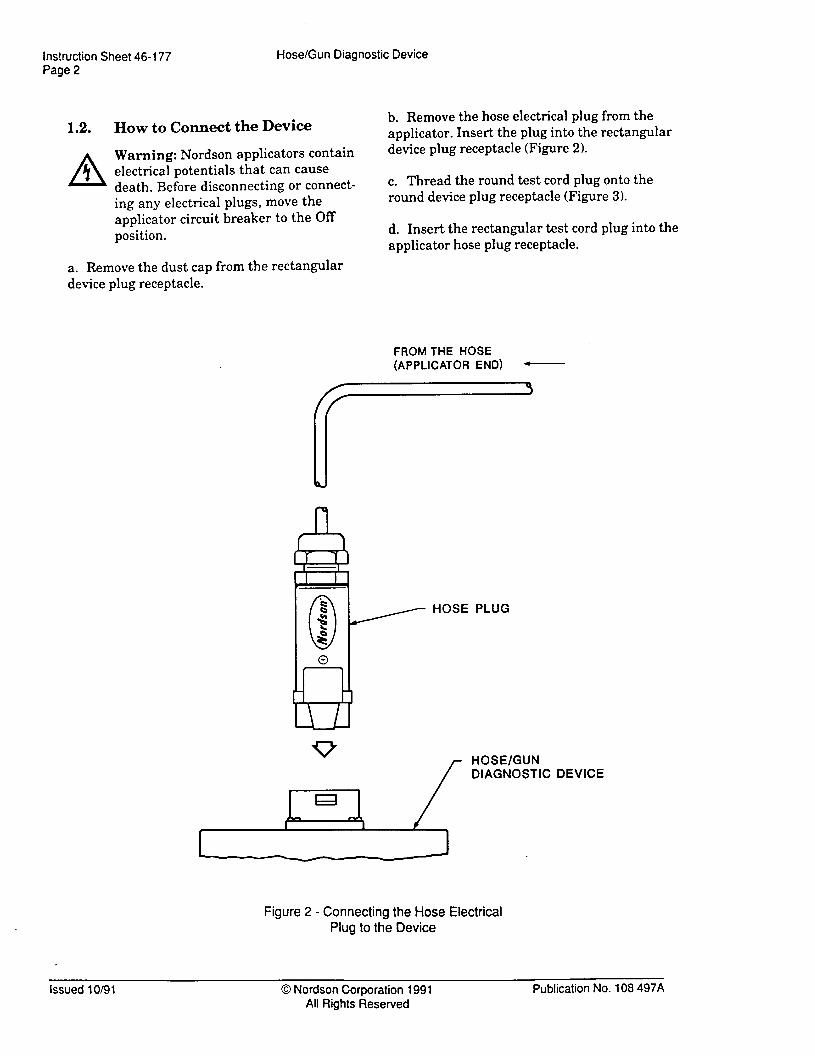
HOW to Connect the Device b. Remove the hose electrical plug from the applicator. Insert the plug into the rectangular
Warning: Nordson applicators contain electrical potentials that can cause death. Before disconnecting or connect- ing any electrical plugs, move the applicator circuit breaker to the Off position,
device plug receptacle (Figure 2).
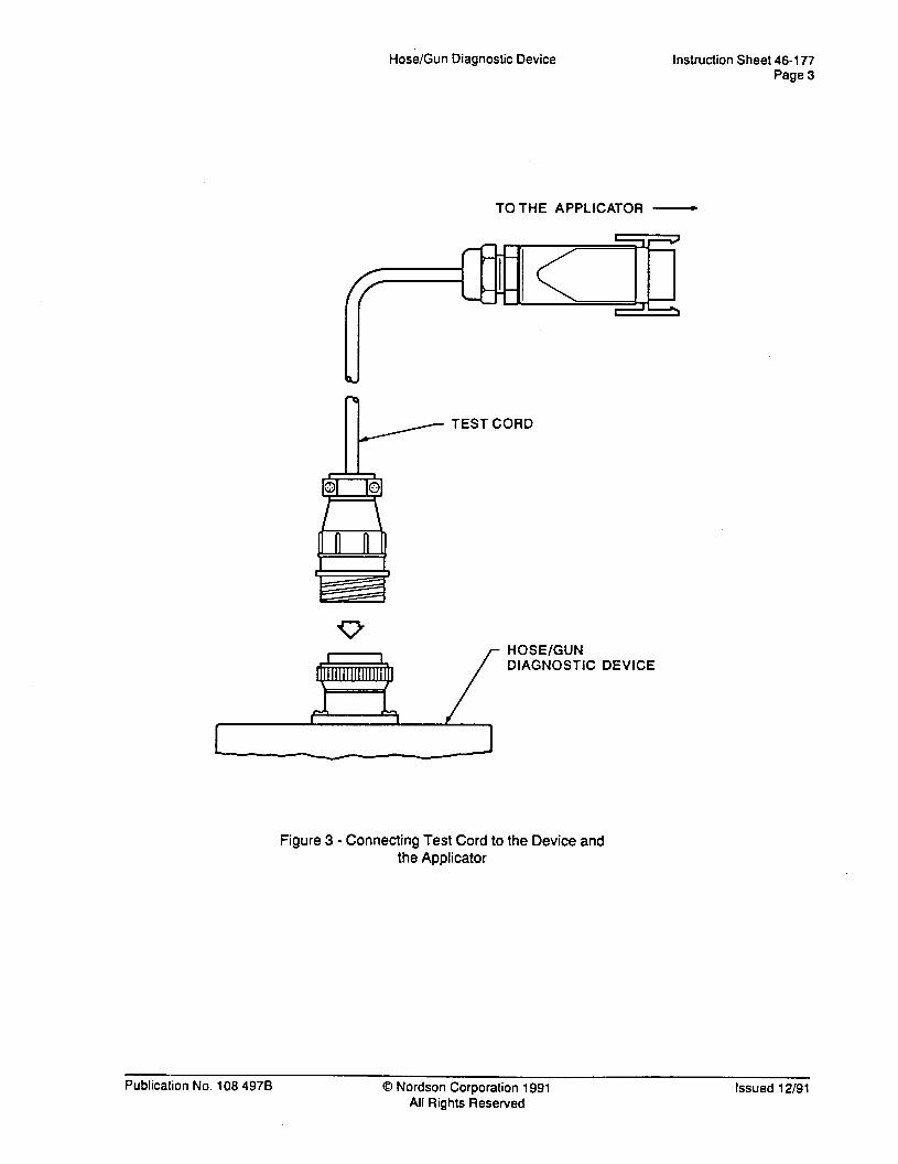
c. Thread the round test cord plug onto the round device plug receptacle (Figure 3).
d. Insert the rectangular test cord plug into the applicator hose plug receptacle.
a. Remove the dust cap from the rectangular device plug receptacle.
FROM THE HOSE (APPLICATOR END) -
HOSE PLUG
/-
HOSE/GUN DIAGNOSTIC DEVICE
P . Figure 2 - Connecting the Hose Electrical
Plug to the Device
Issued 1 O/9 1 0 Nordson Corporation 1991 All Rights Reserved
Publication No. 108 497A
Hose/Gun Diagnostic Device Instruction Sheet 46-177 Page 3
TOTHE APPLICATOR -
TEST CORD
HOSE/GUN DIAGNOSTIC DEVICE
Figure 3 - Connecting Test Cord to the Device and the Applicator
Publication No. 108 4978 0 Nordson Corporatiton 1991 All Rights Reserved
Issued 12/91
Instruction Sheet 46-177 Page 4
Hose/Gun Diagnostic Device
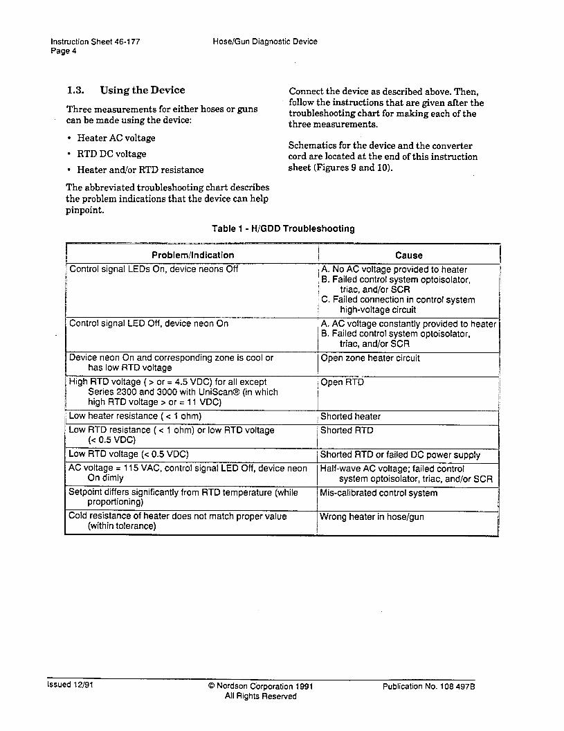
1.3. Using the Device
Three measurements for either hoses or guns can be made using the device:
Connect the device as described above. Then, follow the instructions that are given after the troubleshooting chart for making each of the three measurements.
l Heater AC voltage
l RTD DC voltage
l Heater and/or RTD resistance sheet (‘Figures 9 and 10).
Schem.atics for the device and the converter cord are located at the end of this instruction
The abbreviated troubleshooting chart describes the problem indications that the device can help pinpoint.
Table 1 - H/GDD Troubleshooting
Problem/Indication 1 I Cause I / A. NO AC voltage provided to heater , B. Failed control system optoisolator, I triac, and/or SCR i C. Failed connection in control system
t 1
high-voltage circuit
; A. AC voltage constantly provided to heater B. Failed control system optoisolator,
’ Shorted heater
Low RTD resistance ( < 1 ohm) or low RTD voltage Shorted RTD
’ Shorted RTD or failed DC power supply ’
Half-wave AC voltage; failed control system optoisolator, triac, and/or SCR
Mis-calibrated control system
Wrong heater in hose/gun
Issued 12/91 0 Nordson Cbrporation 1991 All Rights Resewed
Publication No. 108 4976

Hose/Gun Diagnostic Device instruction Sheet 46-177 Page 5
1.3.1.
A
A ‘r
Safety Precautions
Warning: When the applicator input power is connected, high-voltage electri- cal potential that can cause death is accessible at the device test points. Do the following to ensure your safety:
1.3.2. Measuring Heater AC Voltage
a. Ma,ke sure the applicator circuit breaker is in the Off position
1. Keep the vinyl caps on all device test points except the pair that is current- ly being used in testing.
b. Remove the vinyl caps for the first pair of heater test points that will be used (hose or gun, Figure 4).
c. Set the digital volt meter for measuring the 250 V4C scale.
2. Avoid touching the metal surfaces of the test points or the plug receptacles. d. Restore power to the applicator.
Warning: Applying voltage to a digital volt meter when it is set to measure resistance can damage the meter or result in erroneous readings. Make sure that the applicator circuit breaker is in the Off position whenever resis- tance measurements are made.
e. Measure the voltage by inserting the digital volt meter probes into the test points.
HOSE HEATER GUN HEATER AC VOLTAGE AC VOLTAGE
IHOSE
Figure 4 - Hose and Gun AC Voltage Test Points
Publication No. 108 4978 0 Nbrdson Corporation 1991 All Rights Reserved
Issued 12/91

Instruction Sheet 46-177 Page 6
Hose/Gun Diagnostic Device
1.3.3. Measuring RTD DC Voltage
a. Make sure the applicator circuit breaker is in the Off position.
d. Restore power to the applicator.
e. Observing polarity, measure the voltage by inserting the digital volt meter probes into the test points.
b. Remove the vinyl caps for the first pair of heater test points that will be used (hose or gun, Figure 5).
c. Set the digital volt meter for measuring VDC.
IHOSE
HOSE RTD DC VOLTAGE
Figure 5 - Heater and RTD Resistance Test Points
Issued 12/91 0 Nordson Corporation 1991 All Rights Resewed
Publication No. 108 4978

1.3.4. Measuring Heater and/or RTD e. Measure the resistance by inserting the Resistance digital volt meter probes into the test points.
Hose/Gun Diagnostic Device
a. Make sure the applicator circuit breaker is in the Off position.
b. Unplug the end of the test cord that is plugged into the applicator
Instruction Sheet 46-177 Page 7
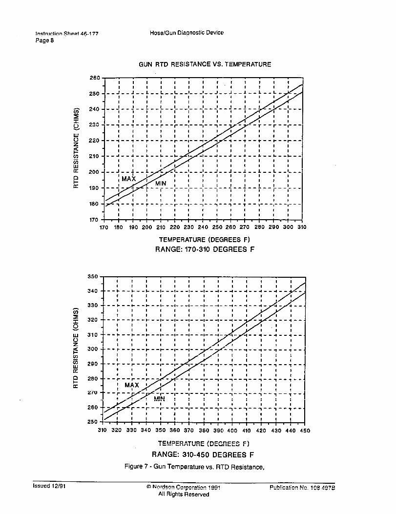
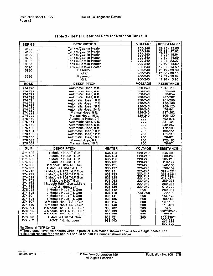
f. Compare the resistance measurement to the resistance shown in the respective gun or hose temperature versus RTD resistance graphs (Figure 7 or 8>, or refer to the information listed in the electrical data reference chart at the back of this instruction sheet.
c. Remove the vinyl caps from the pair of test points that will be measured (heater or RTD, Figure 6).
d. Set the digital volt meter to measure ohms.
HOSE HEATER Q GUN HEATER fl
I HOSE GUN 1
HOSE RTD fi 1 GUN RTD R
Figure 6 - Hose and Gun RTD DC Voltage Test Points
Publication No. 108 4978 0 Nordson Corporation 1991 All Rights Reserved
Issued 12/91
Instruction Sheet 46-177
Page 8
Hose/Gun Diagnostic Device
GUN RTD RESISTANCE VS. TEMPERATURE
260 I f I I I I I I I I I I I
250---:--:--:--:r-L--:---:--:-
I I I I I I I I I I I I I I I I I I I I I I I I I I
170 ‘,‘,‘,‘,‘,‘,~,‘,‘,,,.,.,,,I.
170 180 190 200 210 220 230 240 250 260 270 280 260 360 3iO
TEMPERATURE (DEGREES F)
RANGE: 170-310 DEGREES F
320
200
270
260
250
310 320 330 340 350 360 370 380 398 400 410 420 430 440 450
TEMPERATURE (DEGREES F)
RANGE: 310-450 DElGREES F
Figure 7 - Gun Temperature vs. RTD Resistance,
issued 12/91 0 Nordson Corporation 1991 All Rights Resewed
Publication No. 108 4978

Hose/Gun Diagnostic Device Instruction Sheet 46-177 Page 9
HOSE TTD RESISTANCE VS. TEMPERATURE
270 8 i I I I I I I 1 I I I , I I I I I I I I I I I I I
I I I I I I I I I I I I I I I I I I I I I I I I I I
170 I, I, I, I, I, I, I, I, I, 1, I,. ,I, I
170 180 190 200 210 220 230 240 250 260 270 260 290 300 310
TEMPERATURE (DEGREES F)
RANGE: 170-310 DEGREES F
310 320 330 340 350 360 370 360 39’0 400 410 420 430 440 450
TEMPERATURE (DEGREES F)
RANGE: 310-450 DEGREiES F
Figure 8 - Hose Temperature vs. RTD Resistance
Publication No. 108 4978 0 Nordson Corporation 1991 All Rights Resewed
Issued 12/91
Instruction Sheet 46-177 Page 10
HOSE HUJER POWER
HOSE HEMER POWER
GUN HEATER POWER
GUN HEATER POWER
GUNRTD+
HOSE/GUN RTD COM
Hose/Gun Diagnostic Device
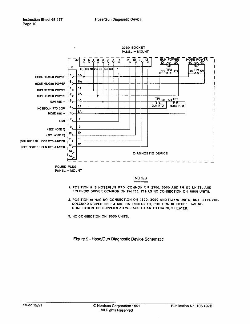
2300 SOCKET PANEL - MOUNT
HOSE RID + IS> 8* 1 I
17 Grn > 7
‘9 9 WENoTEl) , >
(SEE NOTE 2) ,‘O> 10
11 (6EENOTE3) HOSERTDJUMPER 1 >
11
(e NOTE 3) GUN Ill-0 AMPER ,12> 12
13> (14*
DIAGNOSTIC DEVICE
I
I
I I I
I I I
I
I I
I I
I I I I
I I
I --------------------------mm
ROUND PLUG PANEL - MOUNT
NOTES --B.-m-- -----s-
1. POSITION 9 IS HOSE/GUN RTD COMMON ON 2300, 3000 AND FM 170 UNITS, AND SOLENOID DRIVER COMMON ON FM 130. IT HAS NO CONNECTION ON 6000 UNITS.
2. POSITION 10 HAS NO CONNECTION ON 2300, 3000 AND FM 170 UNITS, BUT IS +24 VDC
SOLENOID DRIVER ON FM 130. ON 8000 UNITS, POSITION 10 EITHER HAS NO
CONNECTION OR SUPPLIES AC VOLTAGE TO AN EXTRA GUN HEATER.
3. NO CONNECTION ON 6000 UNITS.
Figure 9 - Hose/Gun Diagnostic Device Schematic
Issued 12/91 0 Nordson Corporation 1991 All Rights Resewed
Publication No. 108 4978

Hose/Gun Diagnostic Device instruction Sheet 46-l 77 Page 11
HOSE HEAfER POWER
HOSE IfEArER POWER
GUN HENER POWER
GUN HEAJER POWER
GUNRTD+
HO!WGUN RTD COM
HO66 RID +
(SEE NOTE 1)
6EENOTE2)
(SEE NOTE 3) HOSE RTD JUMPER
(SEE NOTE 3) GUN RTD AhPER
--------------a
1 A I- -
1 11
I , 12
2300 PLUG FREE -HANGING
I 1 23
2.0 FT. CABLE (TEST CORD) I L i4 I I I ----------------- J
ROUND SOCKET FREE -HANGING
NOTES ----.--- ----.---
1. POSITION 9 IS HOSE/GUN RTD COMMON ON 2300, 3000 AND FM 170 UNITS, AND
SOLENOID DRIVER COMMON ON FM 130. IT HAS NO CONNECTION ON 6000 UNITS.
2. POSITION 10 HAS NO CONNECTION ON 2:300, 3000 AND FM 170 UNITS, BUT IS +24 VDC
SOLENOID DRIVER ON FM 130. ON 6000 IJNITS, POSITION 10 EITHER HAS NO
CONNECTION OR SUPPLIES AC VOLTAGE TO AN EXTRA GUN HEATER.
3. NO CONNECTION ON 6000 UNITS.
Figure 10 - 2.0 Ft. Cable (Test Cord) Schematic
Table 2 - Parts List
Part Number Description Req’d
= 132426 Hose/Gun Diagnostic Device with 2.0 Ft. Cable (Test Cord) Ref
140 995 e Hose/Gun Diagnostic Device (without 2.0 Ft. Cable) 1
131520 l 2.0 Ft. Cable (connects Diagnostic Device to Unit and Hose) 1
Publication No. 108 4976 0 Nordson Corporation 1991 All Rights Reserved
Issued 12/91
Instruction Sheet 46-177 Page 12
Hose/Gun Diagnostic Device
Table 3 - Heater Electrical Data for Nordson Tanks, H
SERIES
3100 3400 3500 3700 3830 3860 3890 3930
3960
HOSE
274 790 274 791 274 792 274 793 274 794 274 795 274 796 274 797
DESCRIPTION
Tank w/Cast-in Heater Tank w/Cast-in Heater Tank w/Cast-in Heater Tank w/Cast-in Heater Tank w/Cast-in Heater Tank w/Cast-in Heater Tank w/Cast-in Heater
Reservoir Grid
Reservoir Grid
DESCRIPTION
Automatic Hose, 2 ft. Automatic Hose, 4 ft. Automatic Hose, 6 ft. Automatic Hose, 8 ft.
Automatic Hose, 10 ft. Automatic Hose, 12 ft. Automatic Hose, 16 ft. Automatic Hose, 24 ft.
Manual Hose, 8 ft. Manual Hose, 16 ft. Automatic Hose, 2 ft Automatic Hose, 4 ft. Automatic Hose, 6 ft. Automatic Hose, 8 ft.
Automatic Hose, 10 ft.
VOLTAGE RESISTANCE*
200-240 28.15 - 32.85 200-240 23.93 - 27.92 200-240 17.09 - 19.94 200-240 12.60 - 14.69 200-240 19.94 - 23.27 200-240 12.60 - 14.69 200-240 12.60 - 14.69 200-240 25.19 - 29.39 200-240 25.86 - 30.18 200-240 17.09 - 19.94 200-240 11.96 - 13.96
VOLTAGE RESISTANCE
220-240 1048-l 158 220-240 503-556 220-240 320-354 220-240 237-262 220-240 181-200 220-240 150-l 66 220-240 109-l 20 220-240 76-84
‘In Ohms at 75’F (24%) *These guns have two heaters wired in arallel. Resistance shown above is for a single heater. The moth heaters shou d be half the number shown above. P
Issued 12/91 0 Nordson Corporation 1991 All Rights Reserved
Publication No. 108 4978