15 SEER, PACKAGE GAS / ELECTRIC UNIT, 2 to 5 TONS 208/230− ...

Page 1 of 16
INSTRUCTION SHEET FOR 208/230/460V CONVERSION
Machine: Created: Date: Part Number:
R4-11kW M. KLECH 22nd Jan 2015 47525980 001 rev D
WARNING: Before starting work, release air pressure from the system and disconnect, lock and tag the main power supply GENERAL INFORMATION: Your unit was wired according to the power supply indicated on the label inside the door. To convert your air compressor to a different voltage, follow these instructions. Kit contents:
Required tools:
¼“ hex socket to remove transformer connection screws.
Phillips head screw drivers for motor starter connections.
Small slot screwdriver for fan connections.
Stubby phillips head screw driver for motor terminal box
5/16“ hex socket for motor terminal nuts.
Torque wrench
Voltage labels, fuses FU2,
and electrical component
labels. These will be used
on both dryer and non
dryer equipped packages.
Dryer equipped units will
also use two wiring
harnesses and two more
fuses FU3 .

Page 2 of 16
For illustration purposes we are detailing the steps to change the voltage from 230 to 460. Converting from 460 to 230 is the reverse of what is shown. 1. CHANGE FUSES FU2
a) If required, change fuses FU2 located on top of transformer as per BOM (or see below).
Item Description Quantity UOM Note
81291601 FUSE, 0.5A 600VAC CCMR 2 EA FU2 for 460V
32203176 FUSE, 1A 600VAC CCMR 2 EA FU2 for 208 and 230V
Remove plastic finger
guard for access to
transformer terminals.
Pull upward from the
ends.
Remove (2) 1
amp fuses
Locate black
plastic clip and
push forward to
lift guard off.
Remove 2 plastic fuse
guards for access to fuses,
see below for tip on
removing fuse guards.

Page 3 of 16
2. CHANGE VOLTAGE OF CONTROL TRANSFORMER T1
a) Change primary transformer tap at top of tranformer to match desired voltage (208V or 230V or 460V). Using the transformer label as a guide, loosen the hex screw and move the wire to proper location.
b) Torque the hex screw to 20 in-lbs.
a) Reattach 3 plastic finger guards.
3. CHANGE MOTOR BREAKER QF4
If required, change QF4 motor breaker as illustrated below.
Install (2) ½
amp fuses,
orient fuses so
the amperage of
fuse shows.
Remove wire “H”
from 230 volt
terminal
Install wire ”H”
to 460 volt
terminal
Apply New label
with 460
information over
existing 230 voltage
label.

Page 4 of 16
a) Locate motor breakers QF4-A and QF4-B on din rail of starter back panel.
b) Torque the screws to 10 in-lb.
Transfer all 230 volt
QF4-B motor
breaker wires to the
460 volt QF4-A
breaker in same
order as removed.
Note it may be
necessary to access
wiring tray and
reposition wires.
Photo showing All
wires now transferred
to 460 volt motor
breaker including the
auxiliary contact
wires
Turn 460 volt breaker
ON.
Turn 230 volt breaker
OFF.
Verify overload setting is
correct, adjust if necessary. Set
QF4-A setting to be one-half
the valve of QF4-B.

Page 5 of 16
4. CHANGE FAN MOTOR CONNECTION M2. a) If required, change fan motor connection in the starter box (connection at KM4).
Star- 460V, Delta – 208 and 230V
460V 208-230V
Retorque connections to 11-in-lbs.
Perform gentle pull
test on previous
wires to validate
they are secured.
Locate fan motor wires at KM4
and remove the yellow, green
and white wires from the
harness. Taking care to keep
remaining wires in proper
order.

Page 6 of 16
5. CHANGE SETTING OF O/L RELAY FA1
Photo showing the
cooling fan wires Yellow,
Green, White wires
separated from cooling
fan wire harness
connections.
Insert the Yellow,
Green, White wire in
terminal strip identified
as “FAN”
Note: Once inserted and
secured, perform a
gentle pull test on each
wire to validate it is
secured.
Open clear protective
window of FA1 O/L
relay. Note: It opens
from right side as
shown.

Page 7 of 16
Figure 1
208V 230V 460V
7.5HP 12.4A 11.2A 5.7A
10HP 16.4A 14.8A 7.4A
15HP 24.6A 22A 11A 6. CHANGE MOTOR CONNECTION M1 If required, open main motor terminal box and change motor connections to achieve desired voltage.
Remove motor
cover using
stubby
screwdriver.
Reset the FA1 O/L relay
setting using figure 1
chart below. Once set,
close window.

Page 8 of 16
NOTE: ALL wires are to
stay in existing locations.
Remove ALL 12 nuts from
motor studs using 5/16“
hex socket.
Remove ALL the
brass jumper bars
from ALL studs
Reinstall six nuts on
the outer studs to help
keep motor wires in
place. .

Page 9 of 16
Install minimum 2
jumper bars across
each horizontal 2
center studs.
There should no other
jumper bars on any
other studs.
Install remaining 6 nuts
on motor studs and torque
to 13.5-35 in-lbs.

Page 10 of 16
MOTOR WIRING DIAGRAMS – FOR REFERENCE
a. Star-Delta connection, high voltage 460V
b. Star-Delta connection, low voltage 208- 230V
7. CHANGE VOLTAGE LABEL.
Replace label CCN 24795221 located inside starter panel door and tick current configuration voltage after completion of wiring conversion. .
NOTE: Ensure the unit is wired in accordance with the wiring diagram located on starter door before putting the unit back into service. Reconnect power supply to properly grounded electrical circuit with specified voltage and fuse protection. Refer to the instruction manual supplied with your air compressor for initial start-up procedures. Verify motor rotation is correct. Verify cooling fan rotation is correct.

Page 11 of 16
8. DRYER KIT If the machine is equipped with a dryer, follow these steps:
34 33
34 33
Transfer wires from top
of breaker to top of fuse
block, keeping the same
order.
Locate dryer breaker.
Locate transformer
(below the dryer
breaker). Remove
plastic finger guards
from transformer
connections.

Page 12 of 16
Long end of 3 wire harness
32
31
Attach wire 31 and 32 of
the long end to the
secondary (outgoing) side
of the transformer.
Replace plastic finger
guard.
Locate 3 –wire harness
containing wires marked
with 31, 32 and GND.
Notice one end of harness
has the outer covering
stripped further (longer)
than the other end.
.
Attach GND here.

Page 13 of 16
32 31
GND 3 1
Attach wire 31 and 32
from the other end of
the harness to the top
of the dryer breaker.
Attach GND.
Locate 2-wire harness
containing wires
marked with 1 and 3.
Attach one end of the
harness to the primary
(incoming) side of the
transformer as shown.

Page 14 of 16
3 1 a) If required, change fuses FU3 (located above dryer) as per BOM (or see below)
Item Description Quantity UOM Note
22220263 FUSE, 4A 600VAC CCMR 2 EA FU3 for 460
22708952 FUSE, 8 AMP TIME DELAY , CLASS CC 2 EA FU3 for 208 and 230V
Open fuse block.
Attach other end of
2-wire harness to
bottom of fuse
block.
Locate fuse block.
Page 15 of 16
Close fuse block.
Check dryer breaker
for “ON” position.
Fuses installed.
Insert small end of
fuse into each port.
Page 16 of 16
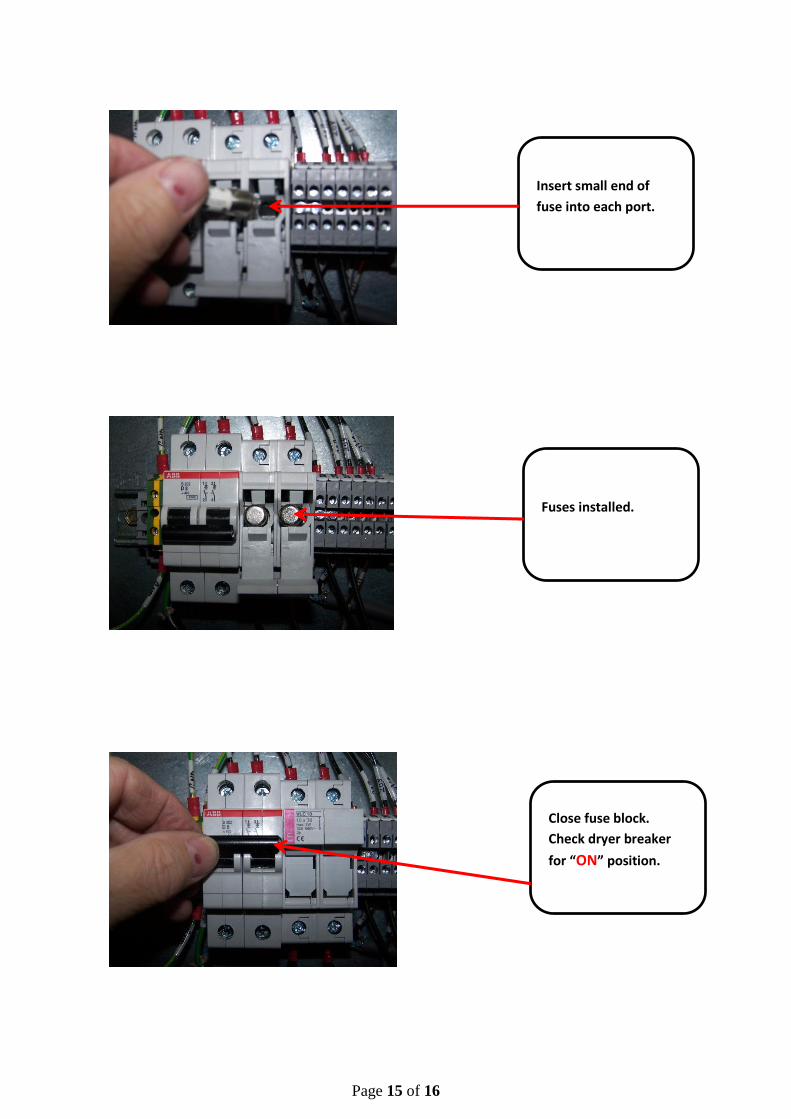
Overall view of completed voltage conversion for dryer equipped units.
NOTE:
Ensure the unit is wired in accordance with the wiring diagram located on starter door before
putting the unit back into service.
Reconnect power supply to properly grounded electrical circuit with specified voltage and fuse
protection.
Refer to the instruction manual supplied with your air compressor for initial start-up
procedures.
Verify motor rotation is correct.
Verify cooling fan rotation is correct.