Instruction Set Architecture simplified DLX – A RISC architecture with only two instruction...
40
Instruction Set Architecture • simplified DLX – A RISC architecture with only two instruction formats. • 32 general purpose registers, each 32 bits wide: R0-R31. • Register R0 always stores the value of 0. • Load and Store operations move data between the general purpose registers and the main memory. • All instructions are represented by a word = 4 bytes = 32 bits. • The DLX architecture also has a few special purpose registers mainly used for handling interrupts. Special move instructions transfer data between general and special purpose registers.
-
date post
20-Dec-2015 -
Category
Documents
-
view
229 -
download
0
Transcript of Instruction Set Architecture simplified DLX – A RISC architecture with only two instruction...
Instruction Set Architecture
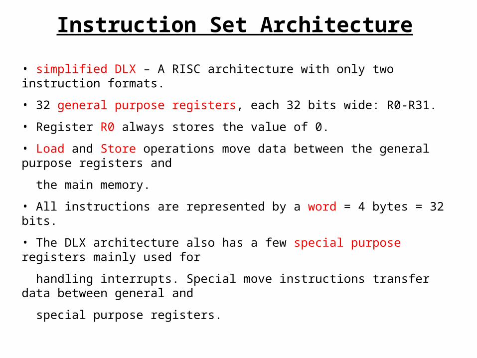
• simplified DLX – A RISC architecture with only two instruction formats.
• 32 general purpose registers, each 32 bits wide: R0-R31.
• Register R0 always stores the value of 0.
• Load and Store operations move data between the general purpose registers and
the main memory.
• All instructions are represented by a word = 4 bytes = 32 bits.
• The DLX architecture also has a few special purpose registers mainly used for
handling interrupts. Special move instructions transfer data between general and
special purpose registers.
The Simplified DLX
An overview of the execution cycle
©Dr. Guy Even
Tel Aviv Univ.
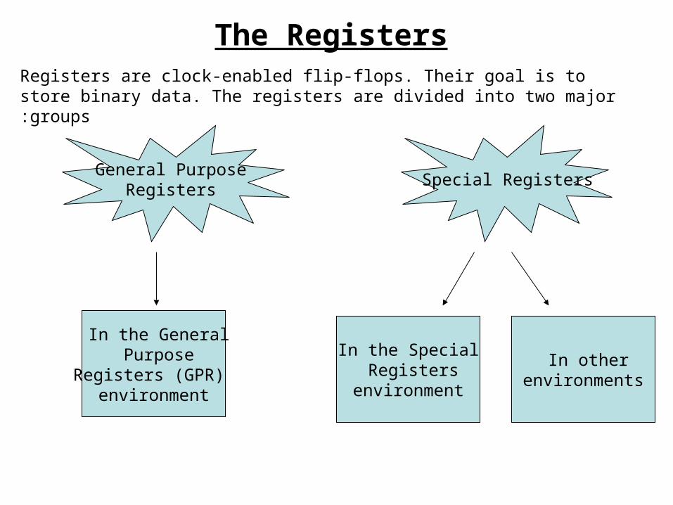
The RegistersRegisters are clock-enabled flip-flops. Their goal is to store binary data. The registers are divided into two major groups:
General PurposeRegisters
Special Registers
In the SpecialRegisters
environment
In other environments
In the General Purpose
Registers (GPR)environment
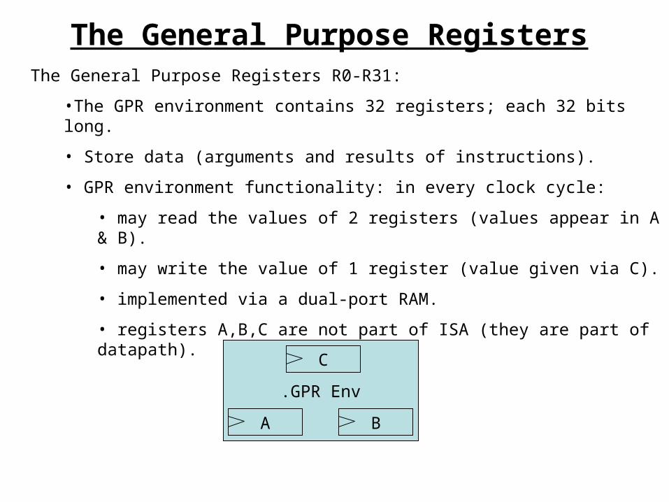
The General Purpose RegistersThe General Purpose Registers R0-R31:
•The GPR environment contains 32 registers; each 32 bits long.
• Store data (arguments and results of instructions).
• GPR environment functionality: in every clock cycle:
• may read the values of 2 registers (values appear in A & B).
• may write the value of 1 register (value given via C).
• implemented via a dual-port RAM.
• registers A,B,C are not part of ISA (they are part of datapath).
GPR Env.
A B
C
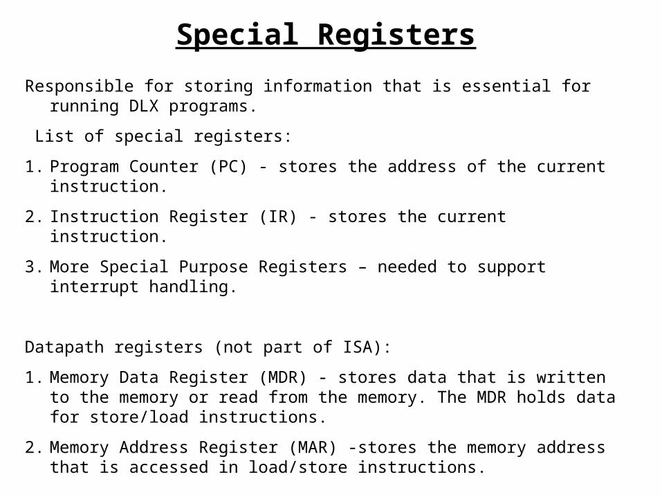
Responsible for storing information that is essential for running DLX programs.
List of special registers:
1. Program Counter (PC) - stores the address of the current instruction.
2. Instruction Register (IR) - stores the current instruction.
3. More Special Purpose Registers – needed to support interrupt handling.
Datapath registers (not part of ISA):
1. Memory Data Register (MDR) - stores data that is written to the memory or read from the memory. The MDR holds data for store/load instructions.
2. Memory Address Register (MAR) -stores the memory address that is accessed in load/store instructions.
Special Registers
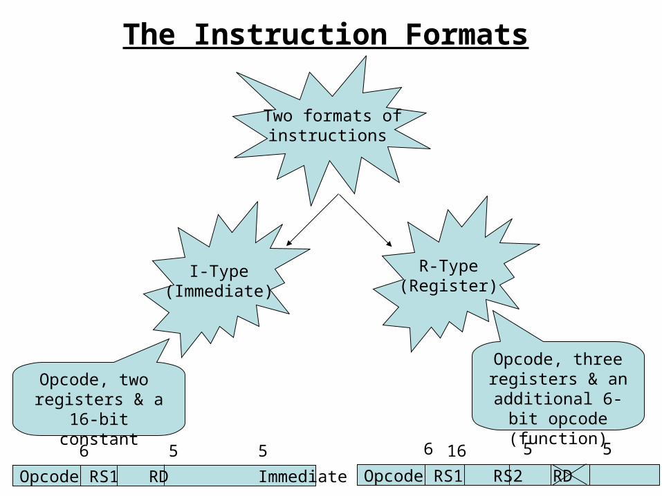
The Instruction Formats
Two formats of instructions
I-Type)Immediate(
R-Type)Register(
Opcode, two registers & a 16-bit
constant
Opcode, three registers & an additional 6-bit
opcode (function)
Opcode RS1 RD Immediate
6 5 5 16
Opcode RS1 RS2 RD Function
6 5 5 5 5 6
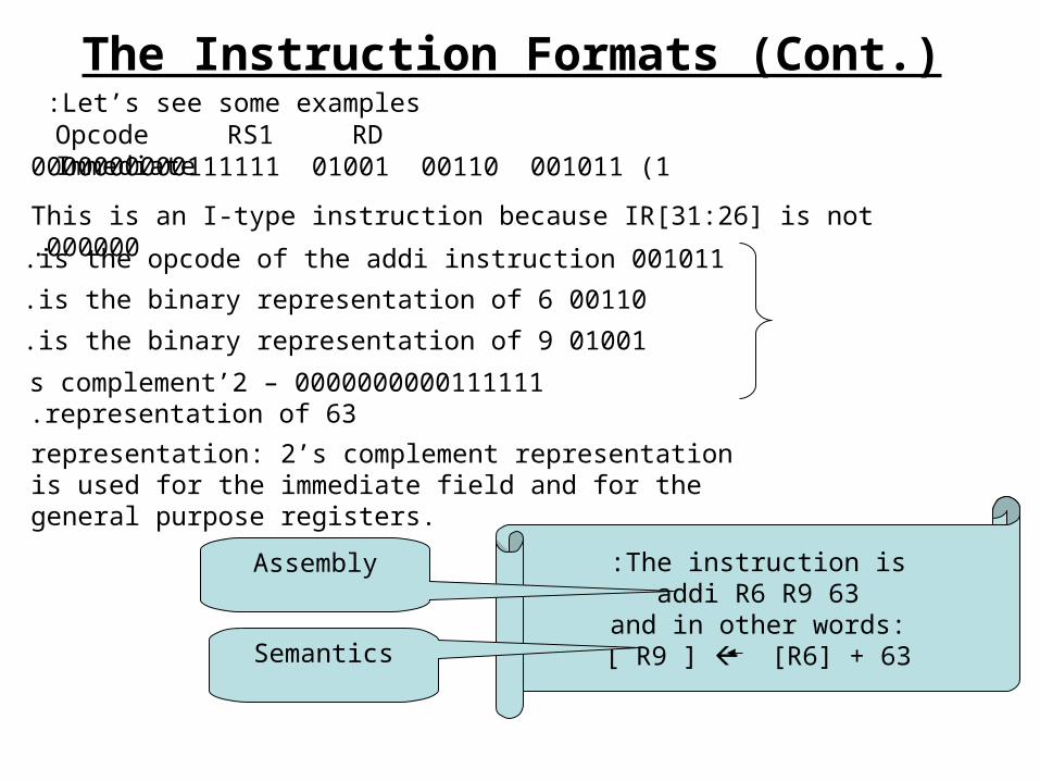
The Instruction Formats (Cont.)Let’s see some examples :
1 (001011 00110 01001 0000000000111111
This is an I-type instruction because IR[31:26] is not 000000.
001011 is the opcode of the addi instruction.
00110 is the binary representation of 6.
01001 is the binary representation of 9.
0000000000111111 – 2’s complement representation of 63.
The instruction is:addi R6 R9 63
and in other words:[ R9 ] [R6] + 63
representation: 2’s complement representation is used for the immediate field and for the general purpose registers.
Opcode RS1 RD Immediate
Assembly
Semantics
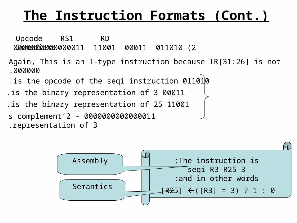
The Instruction Formats (Cont.)
2 (011010 00011 11001 0000000000000011
Again, This is an I-type instruction because IR[31:26] is not 000000.
011010 is the opcode of the seqi instruction.
00011 is the binary representation of 3.
11001 is the binary representation of 25.
0000000000000011 – 2’s complement representation of 3.
The instruction is:seqi R3 R25 3
and in other words:
Opcode RS1 RD Immediate
Assembly
Semantics [R25] ([R3] = 3) ? 1 : 0
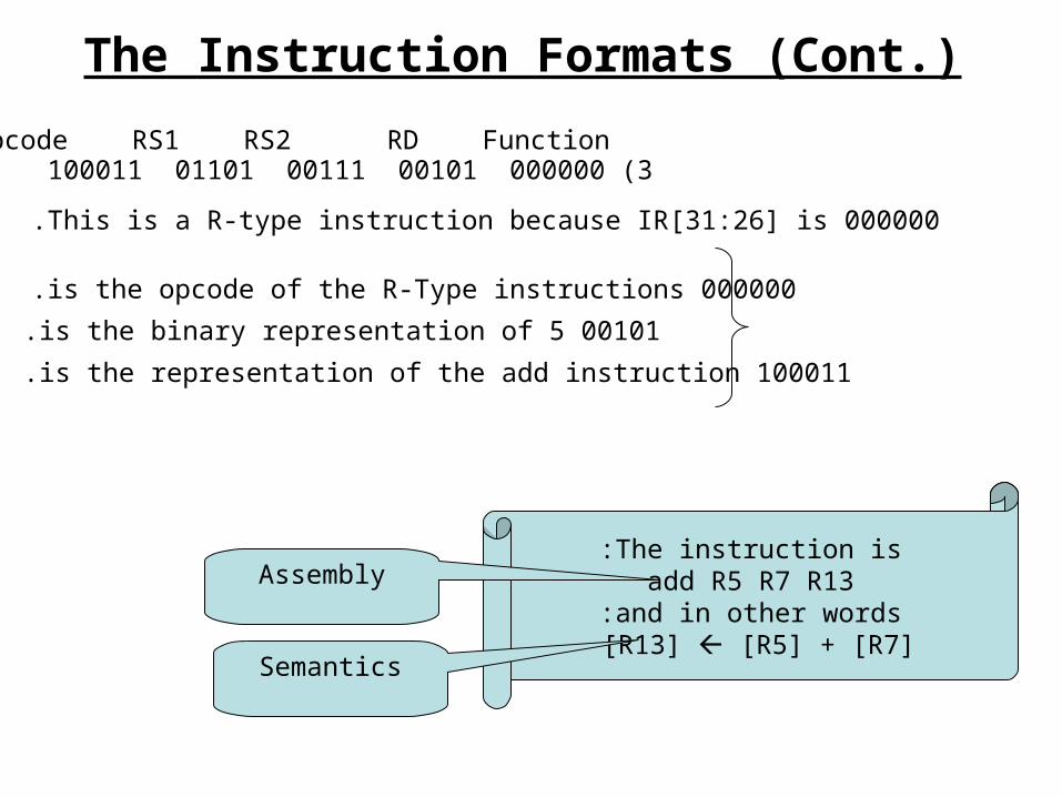
The Instruction Formats (Cont.)
3 (000000 00101 00111 01101 100011
This is a R-type instruction because IR[31:26] is 000000.
000000 is the opcode of the R-Type instructions.
00101 is the binary representation of 5.
100011 is the representation of the add instruction.
The instruction is:add R5 R7 R13
and in other words: [R13] [R5] + [R7]
Assembly
Semantics
Opcode RS1 RS2 RD Function

The Instructions’ Types
Several Types of instructions
Load/Store Immediate Shift/Compute Test Jump
Simplified DLX instruction set
From the programmer’s point of view (ISA):
DLX is a universal machine that executes programs stored in the main memory written in the DLX instructions set.
What is the DLX?
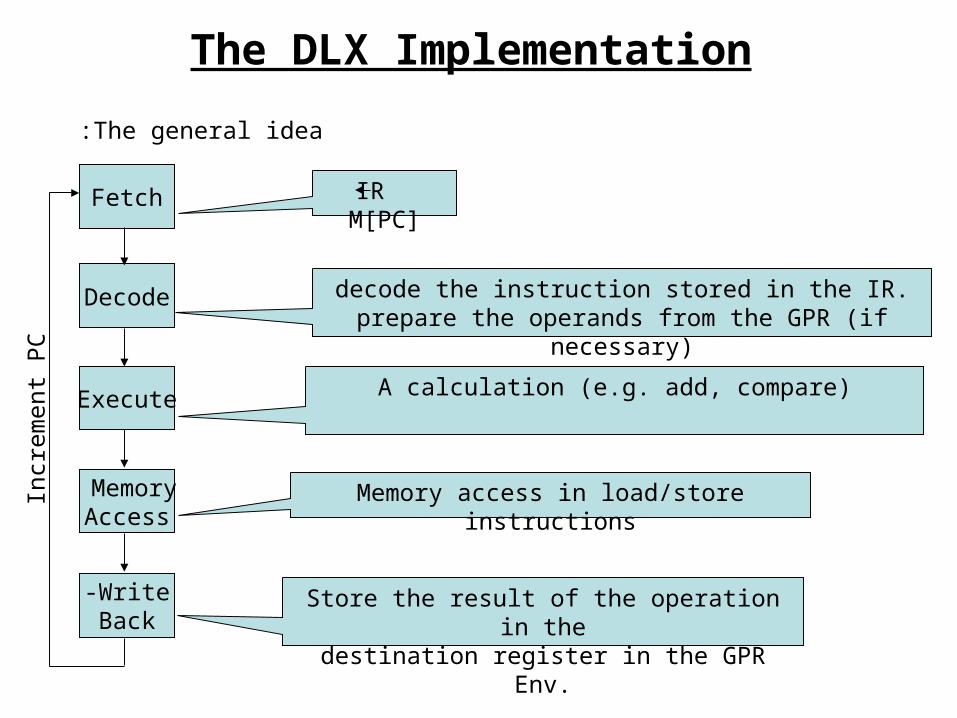
The DLX Implementation
The general idea:
Fetch
Decode
Execute
Memory Access
Write-Back
IR M[PC]
decode the instruction stored in the IR.prepare the operands from the GPR (if necessary)
A calculation (e.g. add, compare)
Memory access in load/store instructions
Store the result of the operation in thedestination register in the GPR Env.
Incr
emen
t P
C
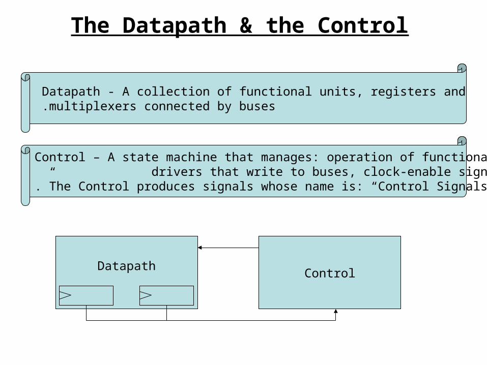
The Datapath & the Control
Datapath - A collection of functional units, registers and multiplexers connected by buses .
Control – A state machine that manages: operation of functional units, drivers that write to buses, clock-enable signals.
The Control produces signals whose name is: “Control Signals.”
DatapathControl
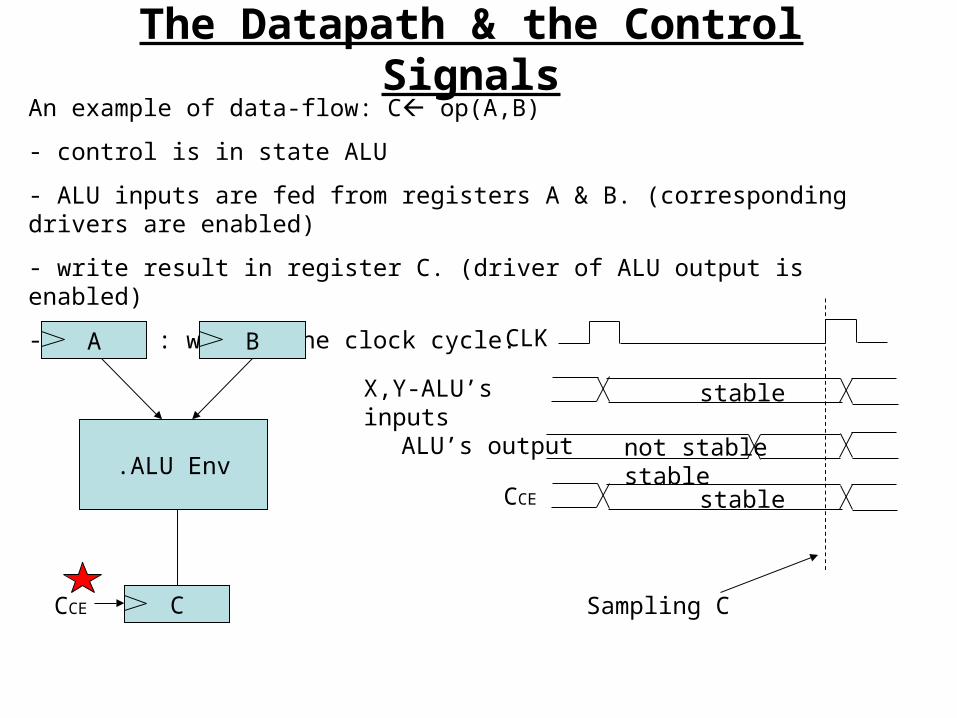
The Datapath & the Control SignalsAn example of data-flow: C op(A,B)
- control is in state ALU
- ALU inputs are fed from registers A & B. (corresponding drivers are enabled)
- write result in register C. (driver of ALU output is enabled)
- timing : within one clock cycle.
A B
ALU Env.
CCCE Sampling C
CLK
stableX,Y-ALU’s inputs
not stable stableALU’s output
stableCCE
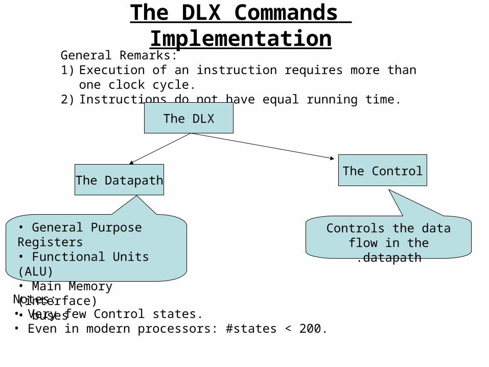
The DLX Commands ImplementationGeneral Remarks:1) Execution of an instruction requires more than one clock cycle.2) Instructions do not have equal running time.
The DLX
The Datapath
• General Purpose Registers • Functional Units (ALU)• Main Memory (interface)• buses
Notes:• Very few Control states.• Even in modern processors: #states < 200.
The Control
Controls the data flow in the datapath.
A reminder: What is the RAM?
RAM = Random Access Memory
The term “Random” means that one may access any word (as oppose to tape in which only next / previous word may be accessed).
The memory is modeled as an array of words. The index of each word
is called the address of the word. M[i] is the word stored in the address of i.
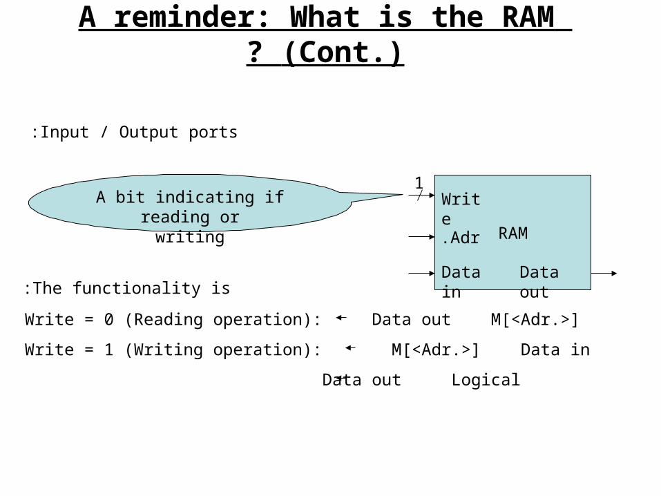
RAM
Write
Adr.
Data in Data out
Input / Output ports:
1A bit indicating if reading or
writing
The functionality is:
Write = 0 (Reading operation): Data out M[<Adr.>]
Write = 1 (Writing operation): M[<Adr.>] Data in
Data out Logical
A reminder: What is the RAM (Cont.)?

In the following slides we will zoom into each of the five types of Control states, describing what happens in each type.
Let’s get deeper
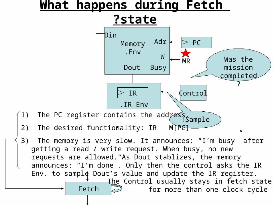
What happens during Fetch state?
DinAdr
Dout
W
Busy
MemoryEnv.
Control
IR Env.
IR
PC
MR Was the mission
completed?
Sample!1) The PC register contains the address.
2) The desired functionality: IR M[PC]
FetchThe Control usually stays in fetch state
for more than one clock cycle
3) The memory is very slow. It announces: “I’m busy” after getting a read / write request. When busy, no new requests are allowed. As Dout stablizes, the memory announces: “I’m done”. Only then the control asks the IR Env. to sample Dout’s value and update the IR register.
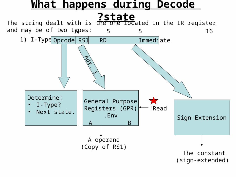
The string dealt with is the one located in the IR register and may be of two types:
1) I-Type: Opcode RS1 RD Immediate
6 5 5 16
Determine:• I-Type?• Next state.
General PurposeRegisters (GPR)
Env.A B
A operand)Copy of RS1(
Adr. 1
Read!
Sign-Extension
The constant )sign-extended(
What happens during Decode state?
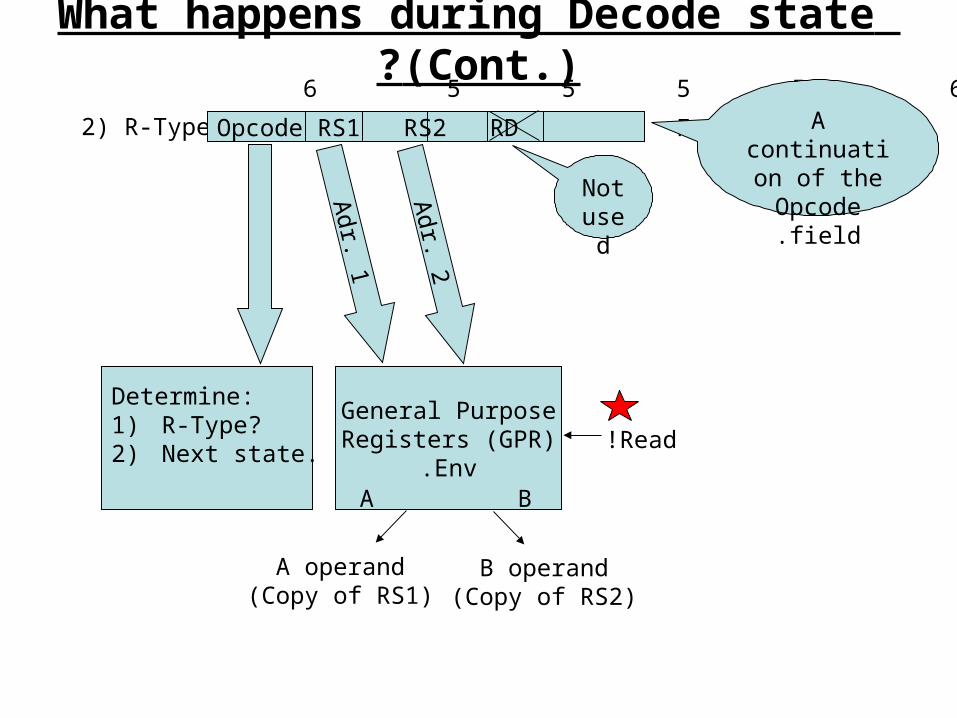
2) R-Type: Opcode RS1 RS2 RD Function
6 5 5 5 5 6
Not used
Determine:1) R-Type?2) Next state.
General PurposeRegisters (GPR)
Env.A B
A operand)Copy of RS1(
Adr. 1
Adr. 2
B operand)Copy of RS2(
Read!
What happens during Decode state (Cont.)?
A continuation
of the Opcode field.
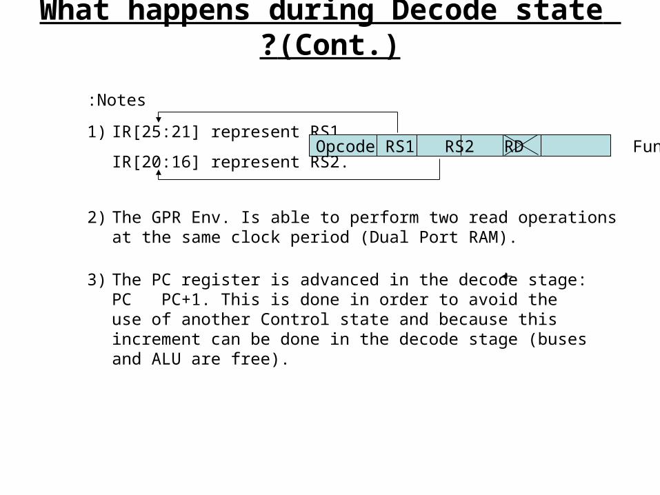
Notes:
1) IR[25:21] represent RS1.
IR[20:16] represent RS2.
2) The GPR Env. Is able to perform two read operations at the same clock period (Dual Port RAM).
3) The PC register is advanced in the decode stage: PC PC+1. This is done in order to avoid the use of another Control state and because this increment can be done in the decode stage (buses and ALU are free).
What happens during Decode state (Cont.)?
Opcode RS1 RS2 RD Function
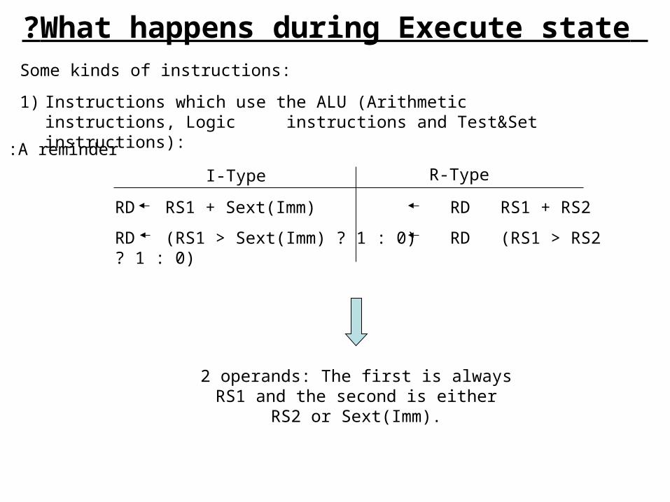
Some kinds of instructions:
1) Instructions which use the ALU (Arithmetic instructions, Logic instructions and Test&Set instructions):
A reminder:
RD RS1 + Sext(Imm) RD RS1 + RS2
RD (RS1 > Sext(Imm) ? 1 : 0) RD (RS1 > RS2 ? 1 : 0)
R-TypeI-Type
2 operands: The first is always RS1 and the second is either RS2 or Sext(Imm).
What happens during Execute state?
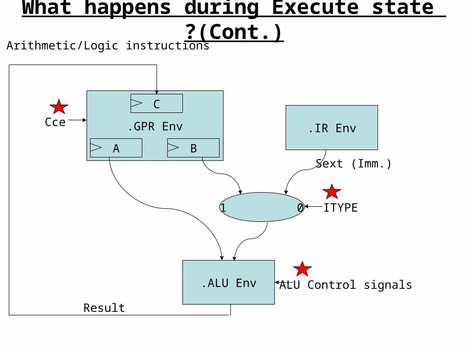
GPR Env.
A B
C
Cce IR Env.
0 1 ITYPE
ALU Env. ALU Control signals
Result
A. Arithmetic/Logic instructions:
What happens during Execute state (Cont.)?
Sext (Imm.)
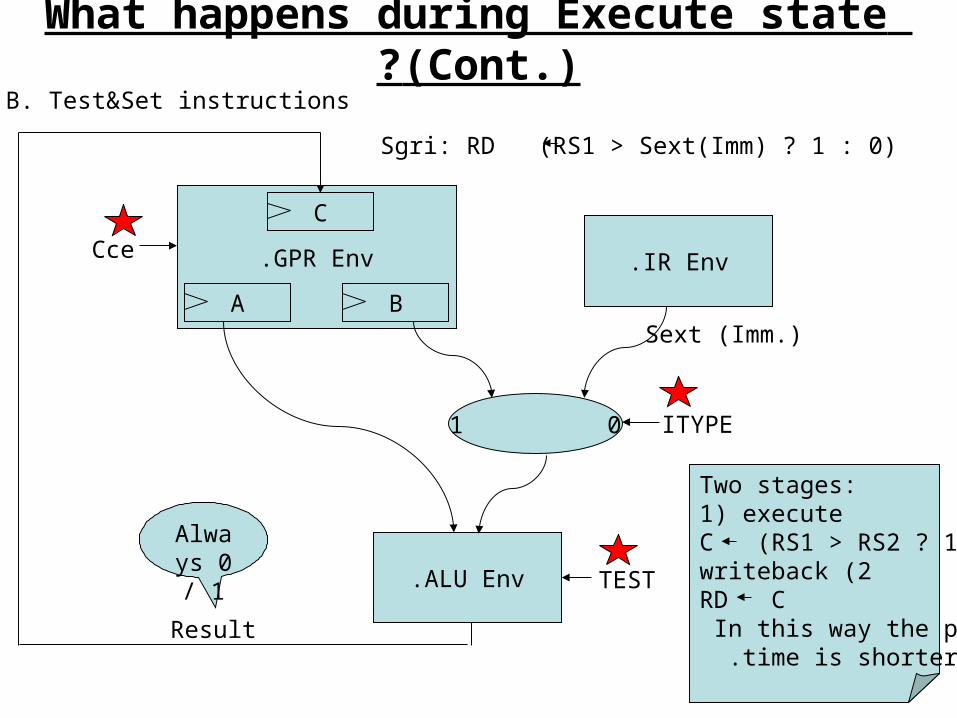
B. Test&Set instructions:
Sgri: RD (RS1 > Sext(Imm) ? 1 : 0)
GPR Env.
A B
C
Cce IR Env.
0 1 ITYPE
ALU Env. TEST
Result
Sext (Imm.)
Two stages:1) executeC (RS1 > RS2 ? 1:0)
2 (writebackRD CIn this way the period
time is shorter .
What happens during Execute state (Cont.)?
Always 0 / 1
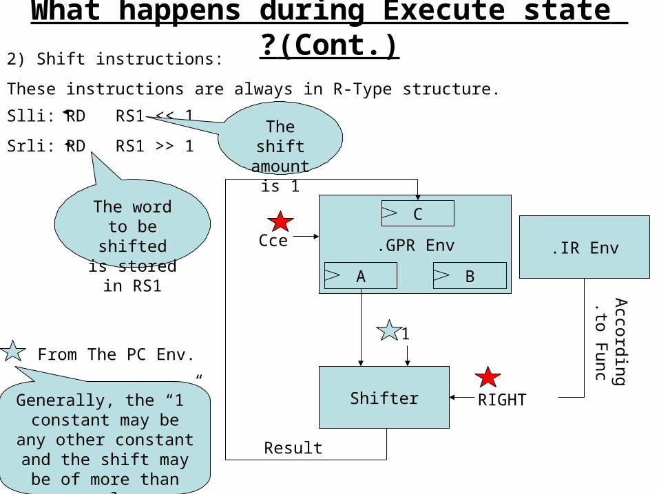
2) Shift instructions:
These instructions are always in R-Type structure.
Slli: RD RS1 << 1
Srli: RD RS1 >> 1
The word to be shifted is
stored in RS1
The shift amount is
1
GPR Env.
A B
C
Cce
Shifter RIGHT
Result
1From The PC Env.
IR Env.
Accordingto F
unc.
What happens during Execute state (Cont.)?
Generally, the “1” constant may be any
other constant and the shift may be of more
than one place
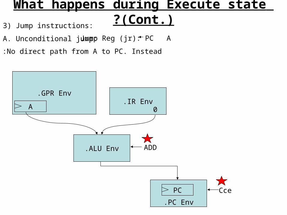
3) Jump instructions:
A. Unconditional jump: Jump Reg (jr): PC A
What happens during Execute state (Cont.)?
No direct path from A to PC. Instead:
GPR Env.
AIR Env.
0
ALU Env. ADD
PC Env.
PC Cce
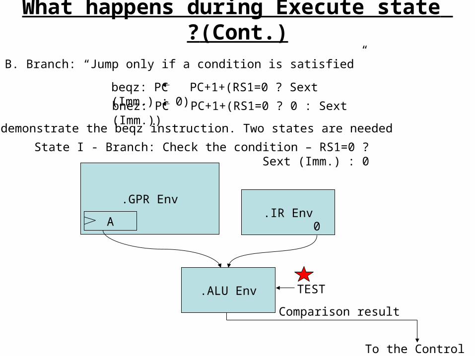
B. Branch: “Jump only if a condition is satisfied”
beqz: PC PC+1+(RS1=0 ? Sext (Imm.) : 0)
bnez: PC PC+1+(RS1=0 ? 0 : Sext (Imm.))
We’ll demonstrate the beqz instruction. Two states are needed:
State I - Branch: Check the condition – RS1=0 ? Sext (Imm.) : 0
GPR Env.
AIR Env.
0
ALU Env. TEST
Comparison result
To the Control
What happens during Execute state (Cont.)?
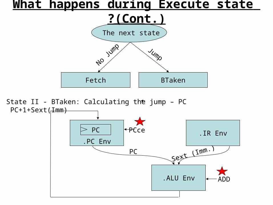
The next state
BTakenFetch
State II - BTaken: Calculating the jump – PC PC+1+Sext(Imm)
IR Env.
ALU Env.
PC Env.
PC PCce
PCSext (Imm.)
ADD
What happens during Execute state (Cont.)?
JumpNo
Jum
p
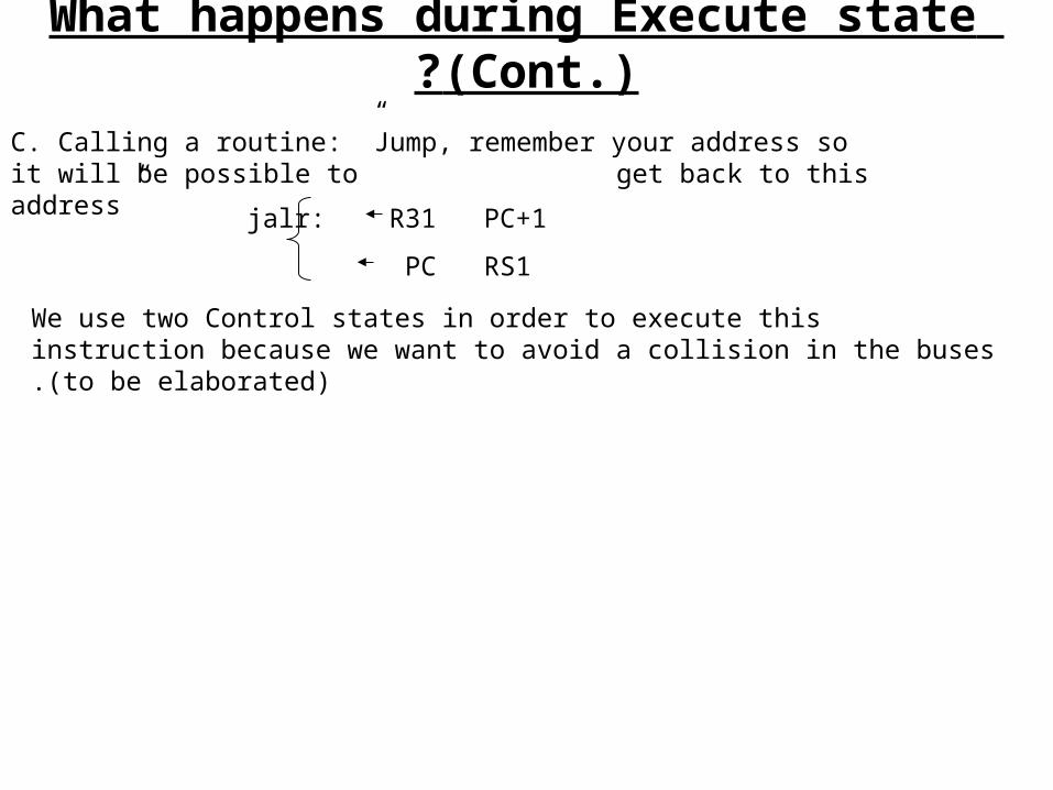
C. Calling a routine: ”Jump, remember your address so it will be possible to get back to this address”
jalr: R31 PC+1
PC RS1
We use two Control states in order to execute this instruction because we want to avoid a collision in the buses (to be elaborated).
What happens during Execute state (Cont.)?
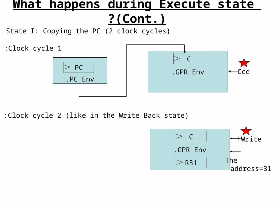
State I: Copying the PC (2 clock cycles)
GPR Env.
C
PC Env.
PC Cce
Clock cycle 1:
GPR Env.
C
R31
Clock cycle 2 (like in the Write-Back state):
Write!
The address=31
What happens during Execute state (Cont.)?
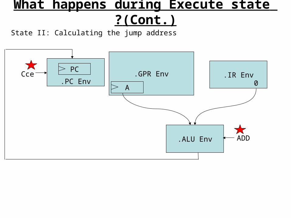
State II: Calculating the jump address
PC Env.
PC
ALU Env.
IR Env.0
GPR Env.
A
ADD
Cce
What happens during Execute state (Cont.)?
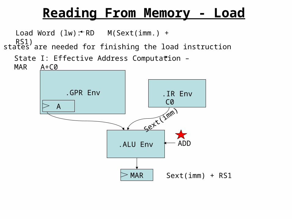
Reading From Memory - Load
Load Word (lw): RD M(Sext(imm.) + RS1)
Four states are needed for finishing the load instruction:
State I: Effective Address Computation – MAR A+C0
GPR Env.
A
IR Env.
ALU Env.
MAR
C0
ADD
Sext(imm) + RS1
Sext(imm)
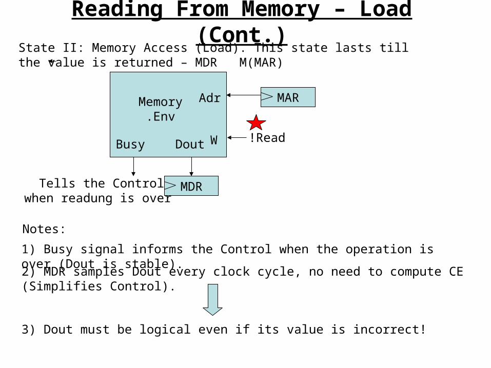
State II: Memory Access (Load). This state lasts till the value is returned – MDR M(MAR)
Reading From Memory – Load (Cont.)
Adr
Dout W
MemoryEnv.
MAR
Read!
MDR
Notes:
1) Busy signal informs the Control when the operation is over (Dout is stable).
2) MDR samples Dout every clock cycle, no need to compute CE (Simplifies Control).
3) Dout must be logical even if its value is incorrect!
Busy
Tells the Control when readung is over
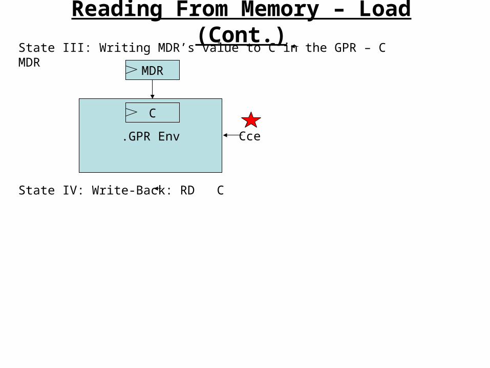
State III: Writing MDR’s value to C in the GPR – C MDR
Reading From Memory – Load (Cont.)
MDR
GPR Env.
C
Cce
State IV: Write-Back: RD C
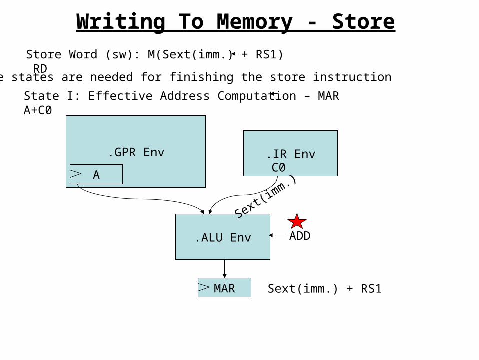
Writing To Memory - Store
Store Word (sw): M(Sext(imm.) + RS1) RD
Three states are needed for finishing the store instruction:
State I: Effective Address Computation – MAR A+C0
GPR Env.
A
IR Env.
ALU Env.
MAR
C0
ADD
Sext(imm.) + RS1
Sext(imm.)
GPR Env.
B
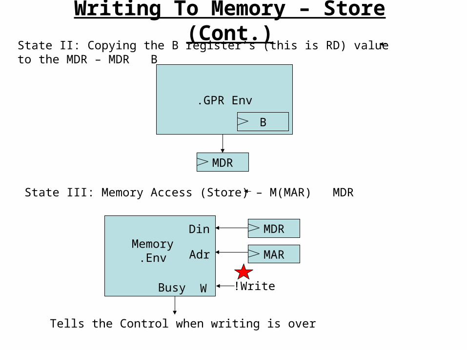
Writing To Memory – Store (Cont.)
MDR
State II: Copying the B register’s (this is RD) value to the MDR – MDR B
State III: Memory Access (Store) – M(MAR) MDR
Adr
W
MemoryEnv. MAR
Write!
MDRDin
Busy
Tells the Control when writing is over
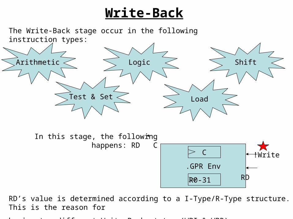
Write-BackThe Write-Back stage occur in the following instruction types:
Arithmetic Logic Shift
Test & Set Load
In this stage, the following happens: RD C
GPR Env.
C
R0-31
Write!
RD
RD’s value is determined according to a I-Type/R-Type structure. This is the reason for
having two different Write-Back states (WBI & WBR).
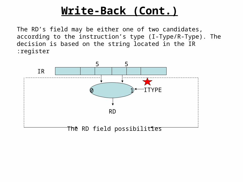
5 5
1 0
RD
ITYPE
IR
The RD field possibilities
Write-Back (Cont.)
The RD’s field may be either one of two candidates, according to the instruction’s type (I-Type/R-Type). The decision is based on the string located in the IR register: