Instruction on the reverse design of a turbomachine with CFturbo on
21
© CFturbo GmbH, 2016 Instruction on the reverse design of a turbomachine with CFturbo on the example of a compressor
Transcript of Instruction on the reverse design of a turbomachine with CFturbo on
© CFturbo GmbH, 2016
Instruction on the reverse design of a turbomachine with CFturbo on the
example of a compressor
Content
1 Preliminary..................................................................................................................................1
1.1 Assumption of best point and fluid properties .....................................................................1
1.2 Setup of the main dimensions of the impeller ......................................................................1
2 Geometric design of the impeller ................................................................................................3
2.1 Generation of reference geometries ....................................................................................3
2.2 Determination of the meridional shape ...............................................................................3
2.3 Blade properties ..................................................................................................................6
2.3.1 Extraction of geometrical dimensions ..........................................................................6
2.3.2 Determination of the blade angles at leading and trailing edge ....................................7
2.4 Mean lines ...........................................................................................................................8
2.4.1 Mean lines of the main blades .....................................................................................8
2.4.2 Mean lines of the splitter blades ..................................................................................9
3 Blade profiles ............................................................................................................................ 11
3.1 Blade thickness .................................................................................................................. 11
3.2 Round leading edge ........................................................................................................... 12
3.3 CFD-Extension ................................................................................................................... 12
4 Radial diffuser ........................................................................................................................... 13
5 Volute ....................................................................................................................................... 14
5.1 Inlet definition ................................................................................................................... 14
5.2 Cross section shape ........................................................................................................... 16
5.3 Spiral geometry ................................................................................................................. 17
5.4 Outlet diffuser geometry ................................................................................................... 18
5.5 Cutwater geometry ........................................................................................................... 18
6 Summary................................................................................................................................... 19
Instruction on the reverse Design of a turbomachine with CFturbo on the example of a compressor
1
1 Preliminary
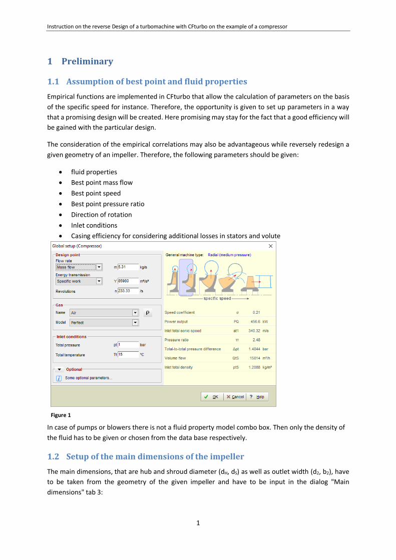
1.1 Assumption of best point and fluid properties
Empirical functions are implemented in CFturbo that allow the calculation of parameters on the basis
of the specific speed for instance. Therefore, the opportunity is given to set up parameters in a way
that a promising design will be created. Here promising may stay for the fact that a good efficiency will
be gained with the particular design.
The consideration of the empirical correlations may also be advantageous while reversely redesign a
given geometry of an impeller. Therefore, the following parameters should be given:
fluid properties
Best point mass flow
Best point speed
Best point pressure ratio
Direction of rotation
Inlet conditions
Casing efficiency for considering additional losses in stators and volute
Figure 1
In case of pumps or blowers there is not a fluid property model combo box. Then only the density of
the fluid has to be given or chosen from the data base respectively.
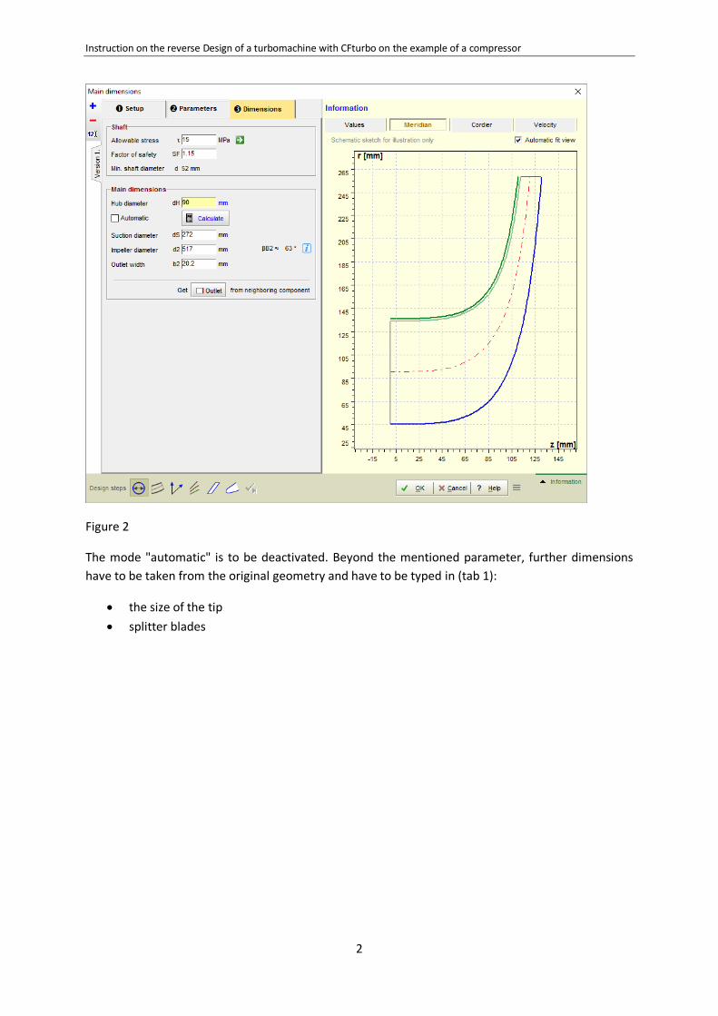
1.2 Setup of the main dimensions of the impeller
The main dimensions, that are hub and shroud diameter (dH, dS) as well as outlet width (d2, b2), have
to be taken from the geometry of the given impeller and have to be input in the dialog "Main
dimensions" tab 3:
Instruction on the reverse Design of a turbomachine with CFturbo on the example of a compressor
2
Figure 2
The mode "automatic" is to be deactivated. Beyond the mentioned parameter, further dimensions
have to be taken from the original geometry and have to be typed in (tab 1):
the size of the tip
splitter blades
Instruction on the reverse Design of a turbomachine with CFturbo on the example of a compressor
3
2 Geometric design of the impeller
2.1 Generation of reference geometries
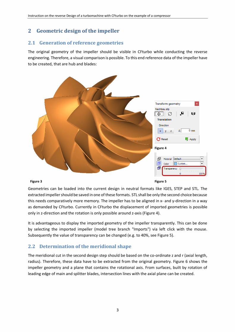
The original geometry of the impeller should be visible in CFturbo while conducting the reverse
engineering. Therefore, a visual comparison is possible. To this end reference data of the impeller have
to be created, that are hub and blades:
Figure 3
Figure 4
Figure 5
Geometries can be loaded into the current design in neutral formats like IGES, STEP and STL. The
extracted impeller should be saved in one of these formats. STL shall be only the second choice because
this needs comparatively more memory. The impeller has to be aligned in x- and y-direction in a way
as demanded by CFturbo. Currently in CFturbo the displacement of imported geometries is possible
only in z-direction and the rotation is only possible around z-axis (Figure 4).
It is advantageous to display the imported geometry of the impeller transparently. This can be done
by selecting the imported impeller (model tree branch "Imports") via left click with the mouse.
Subsequently the value of transparency can be changed (e.g. to 40%, see Figure 5).
2.2 Determination of the meridional shape
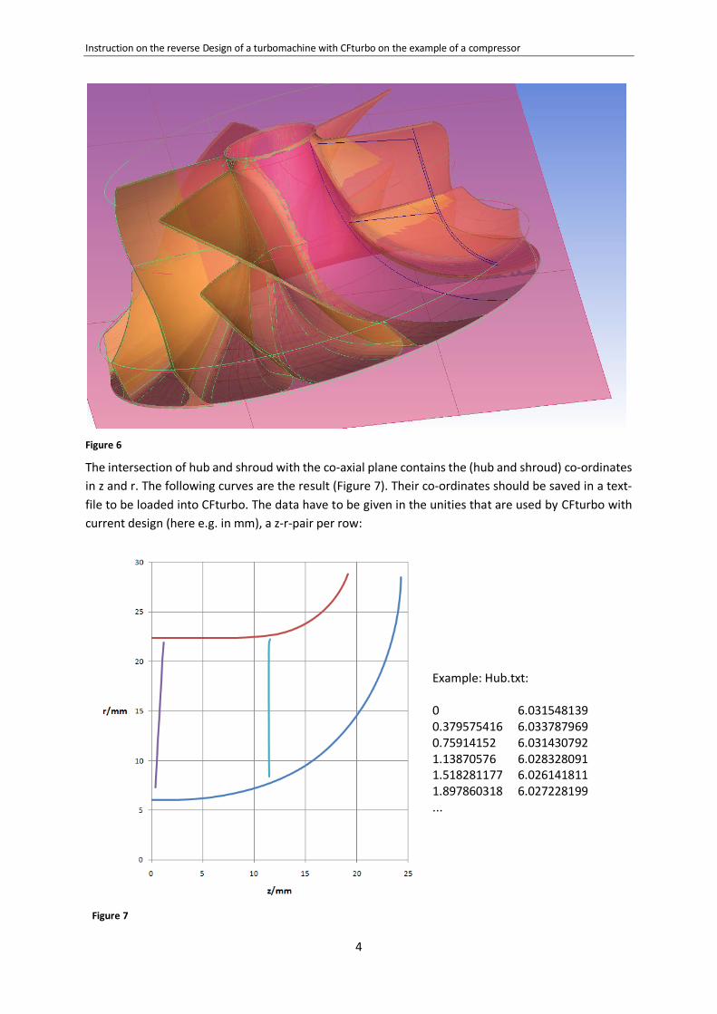
The meridional cut in the second design step should be based on the co-ordinate z and r (axial length,
radius). Therefore, these data have to be extracted from the original geometry. Figure 6 shows the
impeller geometry and a plane that contains the rotational axis. From surfaces, built by rotation of
leading edge of main and splitter blades, intersection lines with the axial plane can be created.
Instruction on the reverse Design of a turbomachine with CFturbo on the example of a compressor
4
Figure 6
The intersection of hub and shroud with the co-axial plane contains the (hub and shroud) co-ordinates
in z and r. The following curves are the result (Figure 7). Their co-ordinates should be saved in a text-
file to be loaded into CFturbo. The data have to be given in the unities that are used by CFturbo with
current design (here e.g. in mm), a z-r-pair per row:
Figure 7
Example: Hub.txt: 0 6.031548139 0.379575416 6.033787969 0.75914152 6.031430792 1.13870576 6.028328091 1.518281177 6.026141811 1.897860318 6.027228199 ...
Instruction on the reverse Design of a turbomachine with CFturbo on the example of a compressor
5
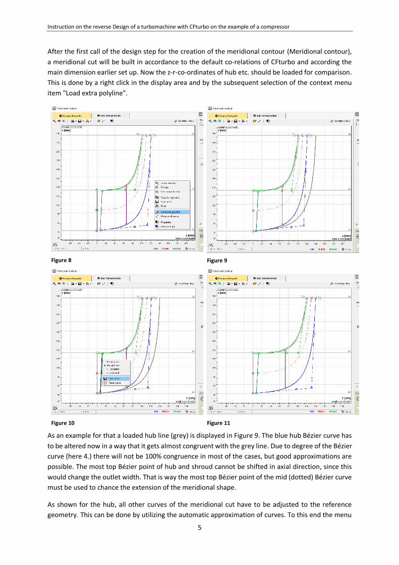
After the first call of the design step for the creation of the meridional contour (Meridional contour),
a meridional cut will be built in accordance to the default co-relations of CFturbo and according the
main dimension earlier set up. Now the z-r-co-ordinates of hub etc. should be loaded for comparison.
This is done by a right click in the display area and by the subsequent selection of the context menu
item "Load extra polyline".
Figure 8
Figure 9
Figure 10
Figure 11
As an example for that a loaded hub line (grey) is displayed in Figure 9. The blue hub Bézier curve has
to be altered now in a way that it gets almost congruent with the grey line. Due to degree of the Bézier
curve (here 4.) there will not be 100% congruence in most of the cases, but good approximations are
possible. The most top Bézier point of hub and shroud cannot be shifted in axial direction, since this
would change the outlet width. That is way the most top Bézier point of the mid (dotted) Bézier curve
must be used to chance the extension of the meridional shape.
As shown for the hub, all other curves of the meridional cut have to be adjusted to the reference
geometry. This can be done by utilizing the automatic approximation of curves. To this end the menu
Instruction on the reverse Design of a turbomachine with CFturbo on the example of a compressor
6
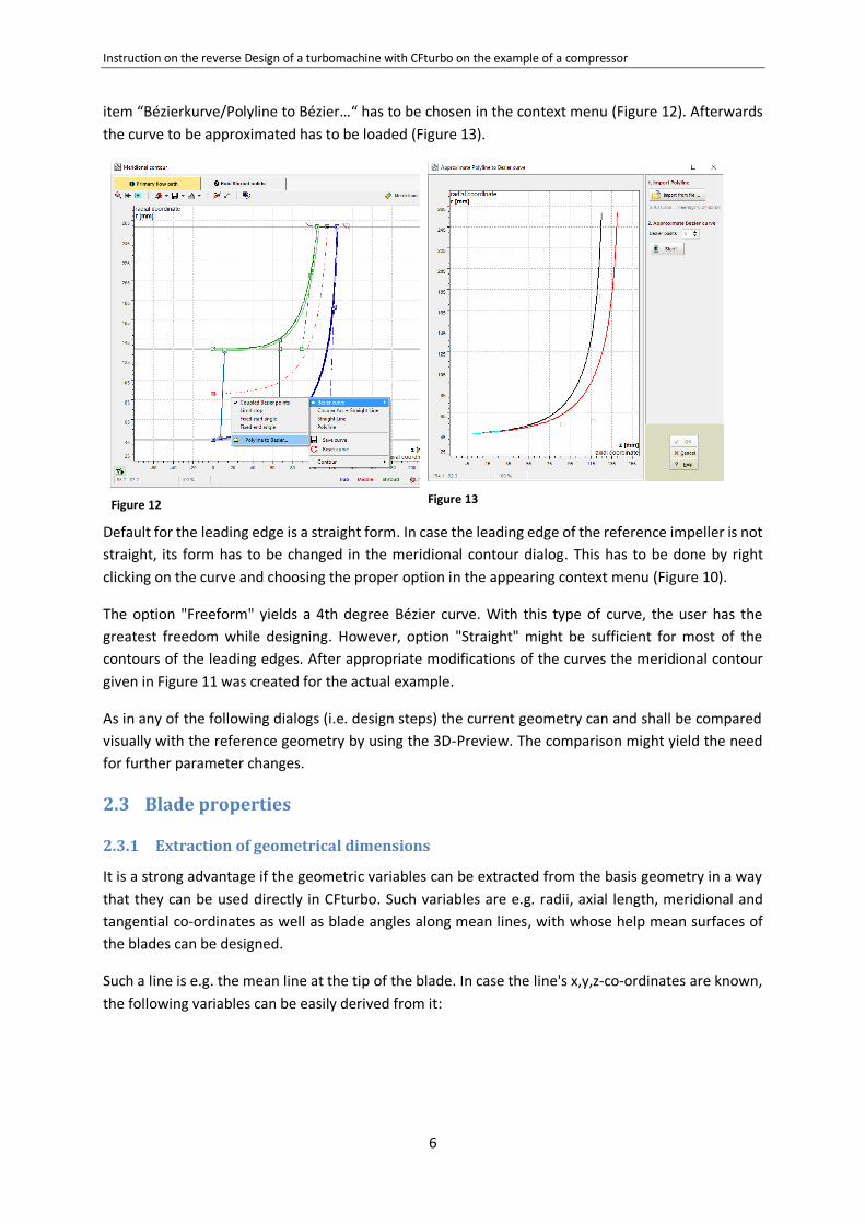
item “Bézierkurve/Polyline to Bézier…“ has to be chosen in the context menu (Figure 12). Afterwards
the curve to be approximated has to be loaded (Figure 13).
Figure 12
Figure 13
Default for the leading edge is a straight form. In case the leading edge of the reference impeller is not
straight, its form has to be changed in the meridional contour dialog. This has to be done by right
clicking on the curve and choosing the proper option in the appearing context menu (Figure 10).
The option "Freeform" yields a 4th degree Bézier curve. With this type of curve, the user has the
greatest freedom while designing. However, option "Straight" might be sufficient for most of the
contours of the leading edges. After appropriate modifications of the curves the meridional contour
given in Figure 11 was created for the actual example.
As in any of the following dialogs (i.e. design steps) the current geometry can and shall be compared
visually with the reference geometry by using the 3D-Preview. The comparison might yield the need
for further parameter changes.
2.3 Blade properties
2.3.1 Extraction of geometrical dimensions
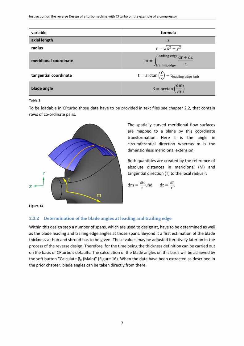
It is a strong advantage if the geometric variables can be extracted from the basis geometry in a way
that they can be used directly in CFturbo. Such variables are e.g. radii, axial length, meridional and
tangential co-ordinates as well as blade angles along mean lines, with whose help mean surfaces of
the blades can be designed.
Such a line is e.g. the mean line at the tip of the blade. In case the line's x,y,z-co-ordinates are known,
the following variables can be easily derived from it:
Instruction on the reverse Design of a turbomachine with CFturbo on the example of a compressor
7
variable formula
axial length z
radius r = √x2 + y2
meridional coordinate m = ∫dr + dz
r
leading edge
trailing edge
tangential coordinate t = arctan (y
x) − tleading edge hub
blade angle β = arctan (dm
dt)
Table 1
To be loadable in CFturbo those data have to be provided in text files see chapter 2.2, that contain
rows of co-ordinate pairs.
The spatially curved meridional flow surfaces
are mapped to a plane by this coordinate
transformation. Here t is the angle in
circumferential direction whereas m is the
dimensionless meridional extension.
Both quantities are created by the reference of
absolute distances in meridional (M) and
tangential direction (T) to the local radius r:
dm =dM
r und dt =
dT
r.
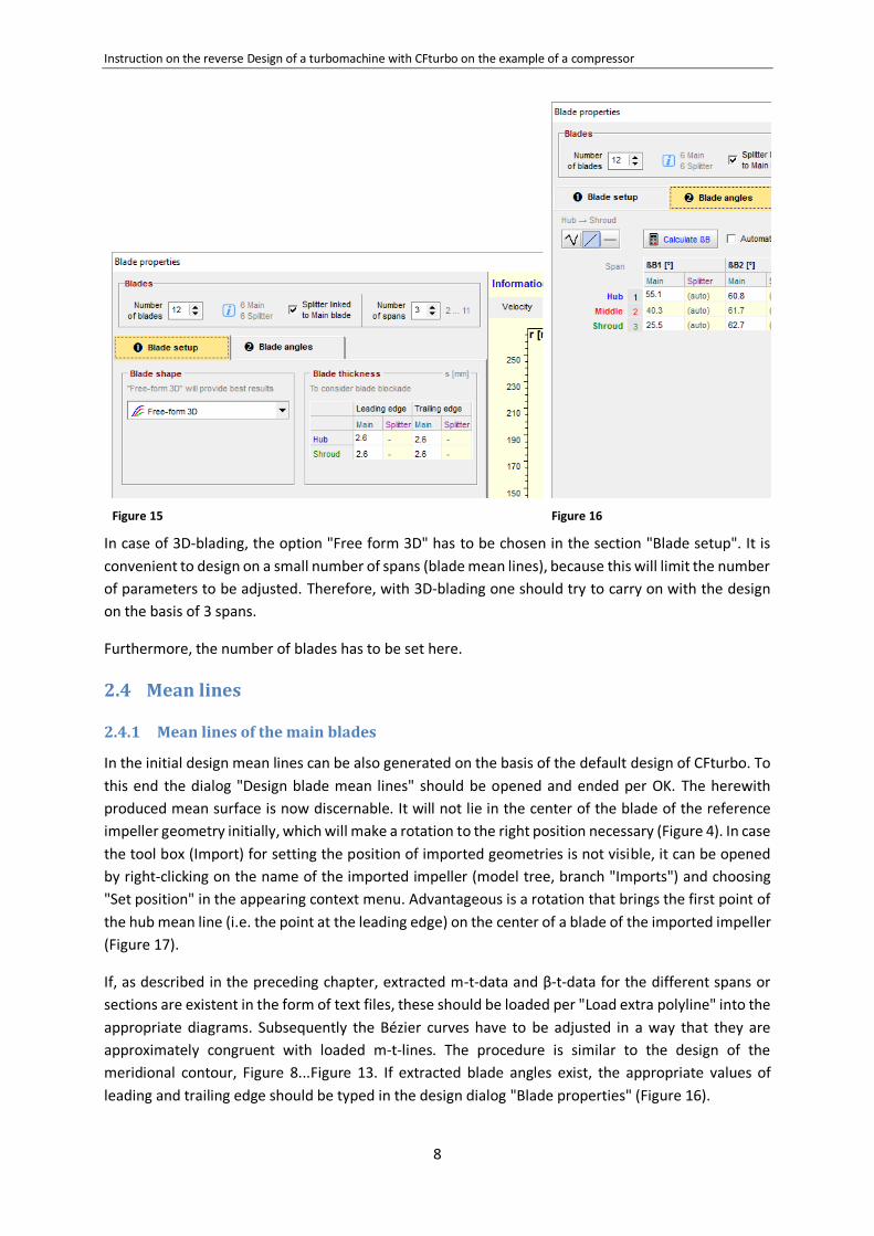
2.3.2 Determination of the blade angles at leading and trailing edge
Within this design step a number of spans, which are used to design at, have to be determined as well
as the blade leading and trailing edge angles at those spans. Beyond it a first estimation of the blade
thickness at hub and shroud has to be given. These values may be adjusted iteratively later on in the
process of the reverse design. Therefore, for the time being the thickness definition can be carried out
on the basis of CFturbo's defaults. The calculation of the blade angles on this basis will be achieved by
the soft button "Calculate βB (Main)" (Figure 16). When the data have been extracted as described in
the prior chapter, blade angles can be taken directly from there.
Figure 14
Instruction on the reverse Design of a turbomachine with CFturbo on the example of a compressor
8
Figure 15
Figure 16
In case of 3D-blading, the option "Free form 3D" has to be chosen in the section "Blade setup". It is
convenient to design on a small number of spans (blade mean lines), because this will limit the number
of parameters to be adjusted. Therefore, with 3D-blading one should try to carry on with the design
on the basis of 3 spans.
Furthermore, the number of blades has to be set here.
2.4 Mean lines
2.4.1 Mean lines of the main blades
In the initial design mean lines can be also generated on the basis of the default design of CFturbo. To
this end the dialog "Design blade mean lines" should be opened and ended per OK. The herewith
produced mean surface is now discernable. It will not lie in the center of the blade of the reference
impeller geometry initially, which will make a rotation to the right position necessary (Figure 4). In case
the tool box (Import) for setting the position of imported geometries is not visible, it can be opened
by right-clicking on the name of the imported impeller (model tree, branch "Imports") and choosing
"Set position" in the appearing context menu. Advantageous is a rotation that brings the first point of
the hub mean line (i.e. the point at the leading edge) on the center of a blade of the imported impeller
(Figure 17).
If, as described in the preceding chapter, extracted m-t-data and β-t-data for the different spans or
sections are existent in the form of text files, these should be loaded per "Load extra polyline" into the
appropriate diagrams. Subsequently the Bézier curves have to be adjusted in a way that they are
approximately congruent with loaded m-t-lines. The procedure is similar to the design of the
meridional contour, Figure 8...Figure 13. If extracted blade angles exist, the appropriate values of
leading and trailing edge should be typed in the design dialog "Blade properties" (Figure 16).
Instruction on the reverse Design of a turbomachine with CFturbo on the example of a compressor
9
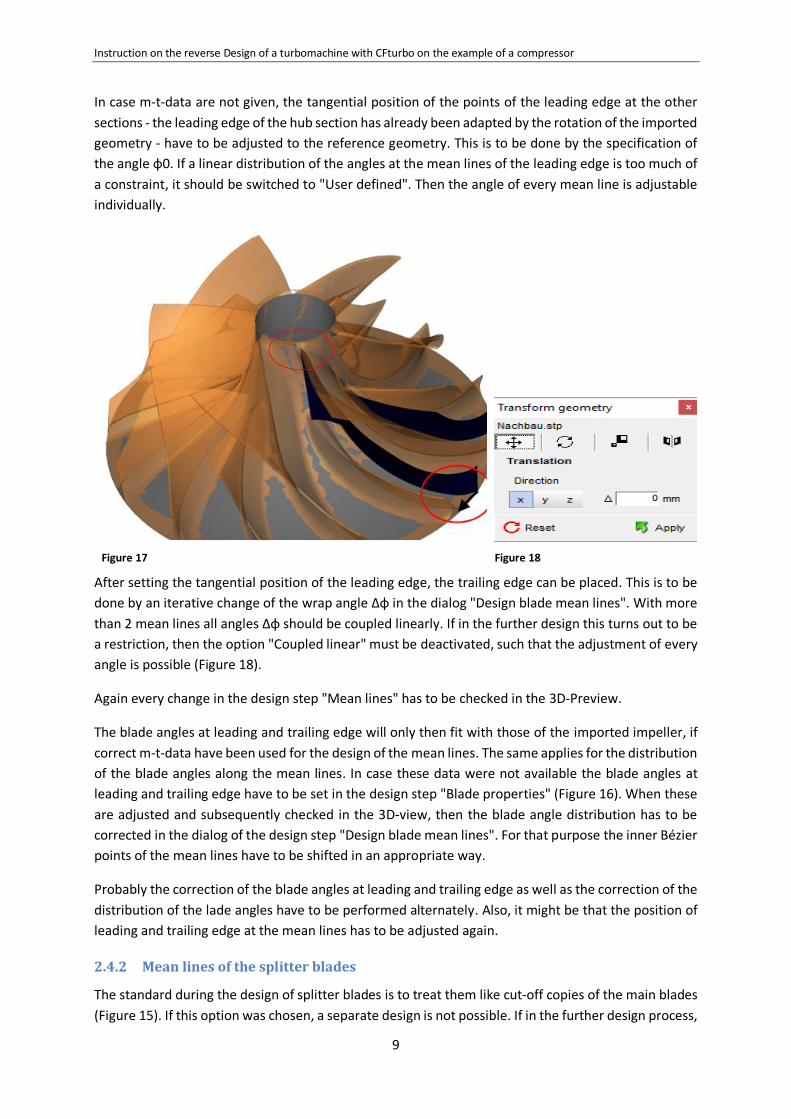
In case m-t-data are not given, the tangential position of the points of the leading edge at the other
sections - the leading edge of the hub section has already been adapted by the rotation of the imported
geometry - have to be adjusted to the reference geometry. This is to be done by the specification of
the angle φ0. If a linear distribution of the angles at the mean lines of the leading edge is too much of
a constraint, it should be switched to "User defined". Then the angle of every mean line is adjustable
individually.
Figure 17
Figure 18
After setting the tangential position of the leading edge, the trailing edge can be placed. This is to be
done by an iterative change of the wrap angle Δφ in the dialog "Design blade mean lines". With more
than 2 mean lines all angles Δφ should be coupled linearly. If in the further design this turns out to be
a restriction, then the option "Coupled linear" must be deactivated, such that the adjustment of every
angle is possible (Figure 18).
Again every change in the design step "Mean lines" has to be checked in the 3D-Preview.
The blade angles at leading and trailing edge will only then fit with those of the imported impeller, if
correct m-t-data have been used for the design of the mean lines. The same applies for the distribution
of the blade angles along the mean lines. In case these data were not available the blade angles at
leading and trailing edge have to be set in the design step "Blade properties" (Figure 16). When these
are adjusted and subsequently checked in the 3D-view, then the blade angle distribution has to be
corrected in the dialog of the design step "Design blade mean lines". For that purpose the inner Bézier
points of the mean lines have to be shifted in an appropriate way.
Probably the correction of the blade angles at leading and trailing edge as well as the correction of the
distribution of the lade angles have to be performed alternately. Also, it might be that the position of
leading and trailing edge at the mean lines has to be adjusted again.
2.4.2 Mean lines of the splitter blades
The standard during the design of splitter blades is to treat them like cut-off copies of the main blades
(Figure 15). If this option was chosen, a separate design is not possible. If in the further design process,

Instruction on the reverse Design of a turbomachine with CFturbo on the example of a compressor
10
it turns out that the splitter blades cannot be composed in the standard way, the option "Splitter blade
linked to main blade" has to be deactivated. Adjacently the design of the mean surface of the splitter
blades has to be carried out in the same way as for the main blades (design step "Design blade mean
lines", second tab), see preceding chapter.
Instruction on the reverse Design of a turbomachine with CFturbo on the example of a compressor
11
3 Blade profiles
3.1 Blade thickness
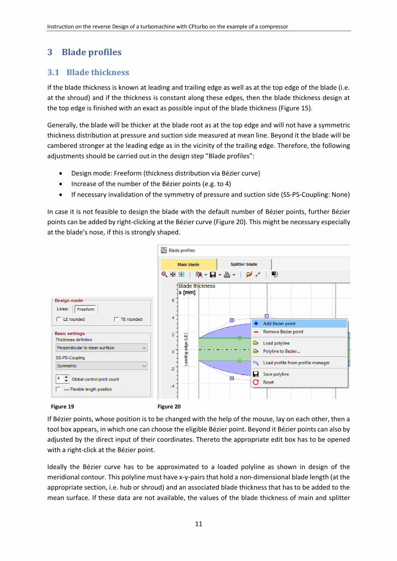
If the blade thickness is known at leading and trailing edge as well as at the top edge of the blade (i.e.
at the shroud) and if the thickness is constant along these edges, then the blade thickness design at
the top edge is finished with an exact as possible input of the blade thickness (Figure 15).
Generally, the blade will be thicker at the blade root as at the top edge and will not have a symmetric
thickness distribution at pressure and suction side measured at mean line. Beyond it the blade will be
cambered stronger at the leading edge as in the vicinity of the trailing edge. Therefore, the following
adjustments should be carried out in the design step "Blade profiles":
Design mode: Freeform (thickness distribution via Bézier curve)
Increase of the number of the Bézier points (e.g. to 4)
If necessary invalidation of the symmetry of pressure and suction side (SS-PS-Coupling: None)
In case it is not feasible to design the blade with the default number of Bézier points, further Bézier
points can be added by right-clicking at the Bézier curve (Figure 20). This might be necessary especially
at the blade's nose, if this is strongly shaped.
Figure 19
Figure 20
If Bézier points, whose position is to be changed with the help of the mouse, lay on each other, then a
tool box appears, in which one can choose the eligible Bézier point. Beyond it Bézier points can also by
adjusted by the direct input of their coordinates. Thereto the appropriate edit box has to be opened
with a right-click at the Bézier point.
Ideally the Bézier curve has to be approximated to a loaded polyline as shown in design of the
meridional contour. This polyline must have x-y-pairs that hold a non-dimensional blade length (at the
appropriate section, i.e. hub or shroud) and an associated blade thickness that has to be added to the
mean surface. If these data are not available, the values of the blade thickness of main and splitter
Instruction on the reverse Design of a turbomachine with CFturbo on the example of a compressor
12
blades have to be adjusted in the given way. The check of these adjustments must be done in the 3D-
Preview.
3.2 Round leading edge
In the design step "Blade edges" three different modes are provided: "Simple", "Ellipse" und "Bézier".
The last option again gives so most comprehensive opportunities for the design and should be chosen,
unless leading and trailing edges shall be trimmed. The adaption of the Bézier curve with the help of
the movement of the Bézier points has again to be checked visually in the 3D-Preview.
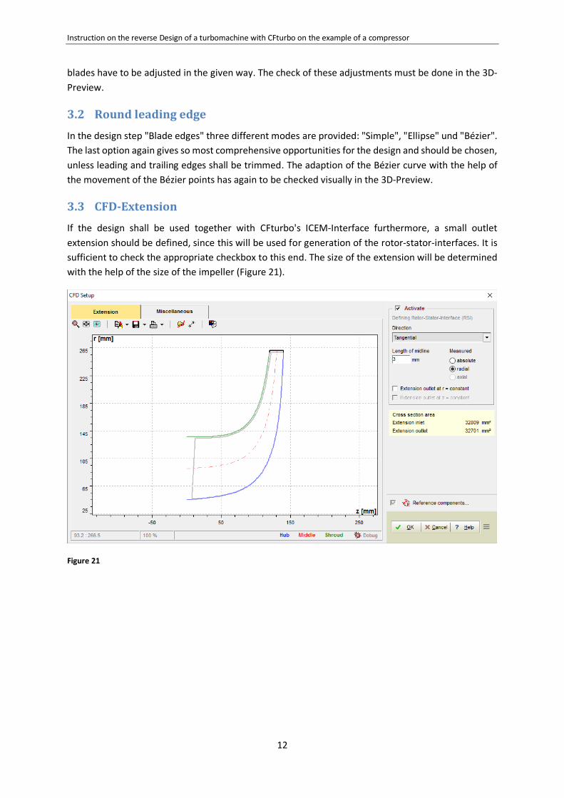
3.3 CFD-Extension
If the design shall be used together with CFturbo's ICEM-Interface furthermore, a small outlet
extension should be defined, since this will be used for generation of the rotor-stator-interfaces. It is
sufficient to check the appropriate checkbox to this end. The size of the extension will be determined
with the help of the size of the impeller (Figure 21).
Figure 21

Instruction on the reverse Design of a turbomachine with CFturbo on the example of a compressor
13
4 Radial diffuser
If a radial diffuser is part of the compressor stage, then inlet and outlet diameter as well as width have
to be determined and also the meridional contour. To this end the same design steps have to be carried
out as described in chapter 1.2 and 2.2.

Instruction on the reverse Design of a turbomachine with CFturbo on the example of a compressor
14
5 Volute
It is recommended to load separate parts of the reference geometry of the volute in accordance to the
respective design step as separate comparing parts into CFturbo. Herewith a visual comparison in
every design step is possible, without interference of parts that are currently not of interest. For the
generation of these individual parts, i.e. vaneless radial diffuser and pinch type diffuser, spiral and
outlet diffuser, see chapter 2.1.
Figure 22
Exemplary two coaxial sections of the spiral as well as the contour of the radial diffuser are displayed
in Figure 22.
5.1 Inlet definition
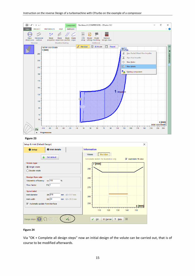
As a starting point in any case the model of the previously designed impeller should be used. For adding
a volute component to the impeller the plus icon at the outlet of the impeller can be pushed followed
by the usage of the menu item "Add new volute" (Figure 23). The result is the open dialog for the
definition of the inlet geometry of the volute, (Figure 24).
Instruction on the reverse Design of a turbomachine with CFturbo on the example of a compressor
15
Figure 23
Figure 24
Via "OK + Complete all design steps" now an initial design of the volute can be carried out, that is of
course to be modified afterwards.
Instruction on the reverse Design of a turbomachine with CFturbo on the example of a compressor
16
In the second tab Volute the inlet values of the spiral geometry have to be set. These are the inlet
diameter dIn and the inlet width bIn.
After the finishing of the first design step "Setup & Inlet" a 3D-geometry will not yet being produced,
which means that a visual comparison with reference geometry is not yet possible. Therefore, in the
further design process of the volute it might be necessary to come back to the diffuser design, in order
to do some modifications of the geometric parameters.
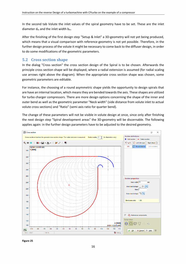
5.2 Cross section shape In the dialog "Cross section" the cross section design of the Spiral is to be chosen. Afterwards the
principle cross section shape will be displayed, where a radial extension is assumed (for radial scaling
use arrows right above the diagram). When the appropriate cross section shape was chosen, some
geometric parameters are editable.
For instance, the choosing of a round asymmetric shape yields the opportunity to design spirals that
are have an internal location, which means they are bended towards the axis. These shapes are utilized
for turbo charger compressors. There are more design options concerning the shape of the inner and
outer bend as well as the geometric parameter "Neck width" (side distance from volute inlet to actual
volute cross sections) and "Ratio" (semi axis ratio for quarter bend).
The change of these parameters will not be visible in volute design at once, since only after finishing
the next design step "Spiral development areas" the 3D-geometry will be discernable. The following
applies again: in the further design parameters have to be adjusted to the desired geometry.
Figure 25
Instruction on the reverse Design of a turbomachine with CFturbo on the example of a compressor
17
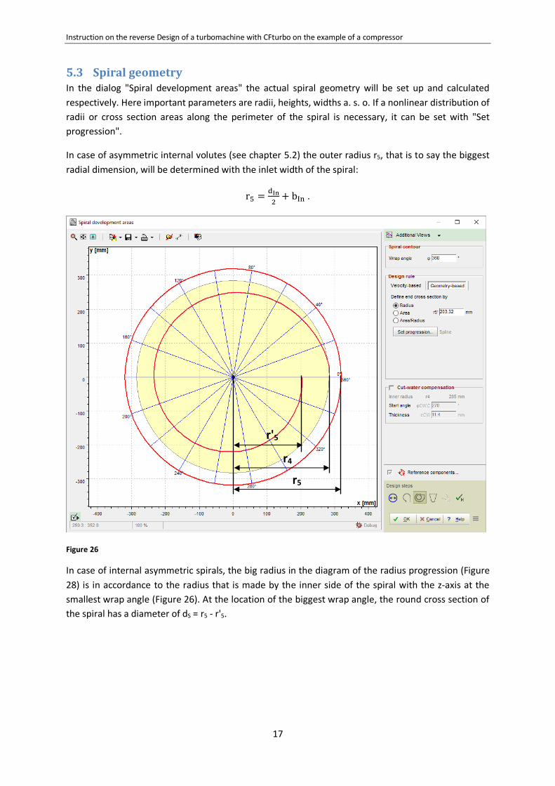
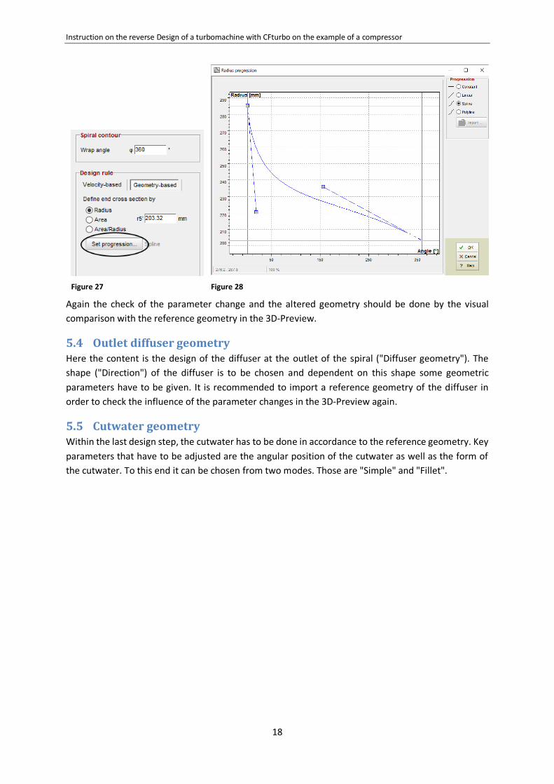
5.3 Spiral geometry In the dialog "Spiral development areas" the actual spiral geometry will be set up and calculated
respectively. Here important parameters are radii, heights, widths a. s. o. If a nonlinear distribution of
radii or cross section areas along the perimeter of the spiral is necessary, it can be set with "Set
progression".
In case of asymmetric internal volutes (see chapter 5.2) the outer radius r5, that is to say the biggest
radial dimension, will be determined with the inlet width of the spiral:
r5 =dIn
2+ bIn .
Figure 26
In case of internal asymmetric spirals, the big radius in the diagram of the radius progression (Figure
28) is in accordance to the radius that is made by the inner side of the spiral with the z-axis at the
smallest wrap angle (Figure 26). At the location of the biggest wrap angle, the round cross section of
the spiral has a diameter of dS = r5 - r'5.
r'5
r4
r5
Instruction on the reverse Design of a turbomachine with CFturbo on the example of a compressor
18
Figure 27
Figure 28
Again the check of the parameter change and the altered geometry should be done by the visual
comparison with the reference geometry in the 3D-Preview.
5.4 Outlet diffuser geometry Here the content is the design of the diffuser at the outlet of the spiral ("Diffuser geometry"). The
shape ("Direction") of the diffuser is to be chosen and dependent on this shape some geometric
parameters have to be given. It is recommended to import a reference geometry of the diffuser in
order to check the influence of the parameter changes in the 3D-Preview again.
5.5 Cutwater geometry Within the last design step, the cutwater has to be done in accordance to the reference geometry. Key
parameters that have to be adjusted are the angular position of the cutwater as well as the form of
the cutwater. To this end it can be chosen from two modes. Those are "Simple" and "Fillet".

Instruction on the reverse Design of a turbomachine with CFturbo on the example of a compressor
19
6 Summary The redesign of impellers with CFturbo works best in case 2D-data are available, that can be loaded
directly into the respective design step where they can be used as a basis for the fitting of the Bézier
curves. Currently these 2D-data must be generated outside CFturbo, see e.g. chapter 2.2.
The checking of the geometric design must be carried out in the 3D-Preview visually in every design
step.
The blade shaping is currently performed in CFturbo on two spans, which are hub and shroud. If free
form 3D blades shall be redesigned, this might not give enough freedom for the design. For milled
compressor impellers probably the switch to the option "ruled surface" (Figure 15) is an opportunity
to match the given reference geometry in the design process.
Bézier curves that are used in CFturbo for the design are often limited with respect to their degree.
This can be possibly not enough to match highly curved geometries.
The outer and inner bend at the transition from the radial diffuser to the spiral (Figure 25) is currently
made of the section of an ellipsis. Again, this is possibly not sufficient for all shapes of bends, in order
to match the reference geometry exactly.