Instruction Manual - YUKEN
82
Instruction Manual - To ensure safe and correct use of the product - ・ To ensure proper handling of the product, read this manual thoroughly before use. ・ Be sure to follow the instructions described in the Safety Precautions section and the main body of this manual. ・ Keep this manual at hand for future reference. ・ When creating instruction manuals for systems equipped with the product, be sure to reflect the contents of this manual in such documents. YUKEN KOGYO CO., LTD. Doc. No. Pub. EM-0146-8 Date of issue July 17, 2013 Products Publicity Section, Sales Administration Dept. ASE Series AC Servo Motor-Driven Pumps Model: ASE3 -*AA-G 80*-B00-31 : ASE5 -*BZ-G130*-B00-31 : ASE10-4CE-G200*-B00-21
Transcript of Instruction Manual - YUKEN
Instruction Manual
- To ensure safe and correct use of the product - ・ To ensure proper handling of the product, read this manual thoroughly before use.
・ Be sure to follow the instructions described in the Safety Precautions section and
the main body of this manual.
・ Keep this manual at hand for future reference.
・ When creating instruction manuals for systems equipped with the product, be sure
to reflect the contents of this manual in such documents.
YUKEN KOGYO CO., LTD.
Doc. No. Pub. EM-0146-8
Date of issue July 17, 2013
Products Publicity Section,
Sales Administration Dept.
ASE Series AC Servo Motor-Driven Pumps
Model: ASE3 -*AA-G 80*-B00-31
: ASE5 -*BZ-G130*-B00-31
: ASE10-4CE-G200*-B00-21

EM-0146-8
- - 1
―――――――About this manual――――――― ・ Some figures and illustrations in this manual are simplified and may not be an exact
representation of the product. ・ The contents of this manual are subject to change without prior notice as improvements
are made to the product. ・ Although this manual has been prepared with great care, please contact the place of
purchase or our customer support if you find any ambiguous explanations, errors, or omissions.
・ If there are missing pages or erratic pagination in this manual, please contact our
customer support. We will replace the manual. ・ Reprint, reproduction, or modification of this manual without the permission of YUKEN
KOGYO CO., LTD. is prohibited.
――――――――――――――――――――――
EM-0146-8
- - 2
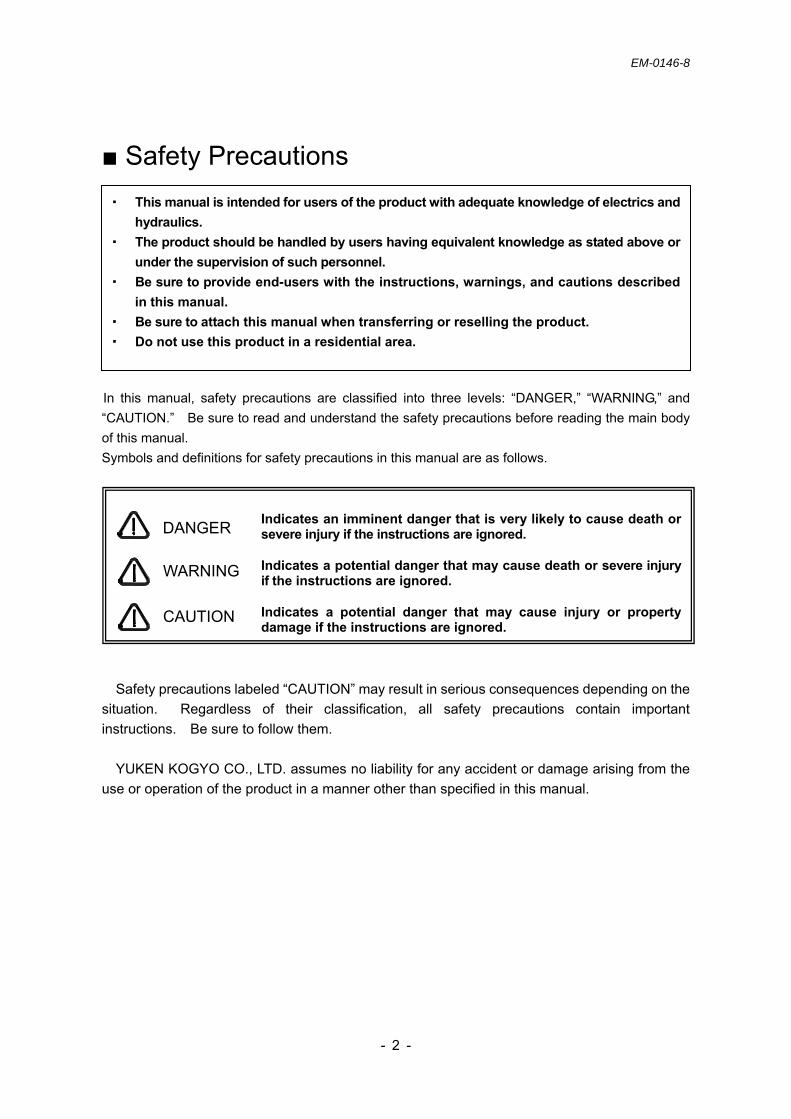
Safety Precautions
In this manual, safety precautions are classified into three levels: “DANGER,” “WARNING,” and “CAUTION.” Be sure to read and understand the safety precautions before reading the main body of this manual. Symbols and definitions for safety precautions in this manual are as follows.
Safety precautions labeled “CAUTION” may result in serious consequences depending on the situation. Regardless of their classification, all safety precautions contain important instructions. Be sure to follow them.
YUKEN KOGYO CO., LTD. assumes no liability for any accident or damage arising from the
use or operation of the product in a manner other than specified in this manual.
・ This manual is intended for users of the product with adequate knowledge of electrics and hydraulics.
・ The product should be handled by users having equivalent knowledge as stated above or under the supervision of such personnel.
・ Be sure to provide end-users with the instructions, warnings, and cautions described in this manual.
・ Be sure to attach this manual when transferring or reselling the product. ・ Do not use this product in a residential area.
Indicates an imminent danger that is very likely to cause death or severe injury if the instructions are ignored. Indicates a potential danger that may cause death or severe injury if the instructions are ignored. Indicates a potential danger that may cause injury or property damage if the instructions are ignored.
DANGER
WARNING
CAUTION

EM-0146-8
- - 3
Always follow the safety precautions Never use the product in an explosive atmosphere where flammable gases or explosives are
handled. Doing so may result in a fatal accident, such as fire or explosion. Never perform wiring, assembly, or maintenance/inspection work with the product powered on.
Doing so may cause electric shock, resulting in a fatal accident. Before wiring, installation, relocation, or inspection, shut off the power supply and wait 15
minutes or more. When the CHARGE lamp of the AMSE controller turns off, perform a voltage check using a tester and then conduct the work.
Do not use an input power supply not specified. Doing so may cause overheat, resulting in
fire. Do not modify or disassemble the product. Doing so may impair safe operation. Install the AMSE controller and regenerative resistors on nonflammable objects. Any
flammable object near them may be heated, causing fire. Be sure to connect the ground wire as a precaution against electric shock in the event of earth
leakage. Never connect the ground wire to the following. - Gas pipe - Lightning rod - Water pipe/faucet - Telephone line ground
Handling of emergencies If the product begins to smoke
The continuous use of the product under abnormal conditions, such as smoking or unusual odors, may result in fire or electric shock. Immediately shut off the power supply and contact your local customer service after checking that the smoke has stopped. The repair of the product by users is dangerous. The users should never attempt repairs.
If the product is broken If the product is dropped or pulled down, immediately shut off the power supply and contact your local customer service. Continuous use without taking corrective measures may result in fire or electric shock.
If water gets into the product If water gets into the product, immediately shut off the power supply and contact your local customer service. Continuous use without taking corrective measures may result in fire or electric shock.
Do not put any object in the pump. Doing so may damage the pump’s internal parts during operation.
During operation or for some time after a power-off, the motor frame temperature is high. Prevent hands or other body parts from contacting the frame in order to avoid burn.
Do not step on or put any heavy object on the product. Doing so may result in damage to the product/equipment or injury from collapse/falling.
WARNING
DANGER
CAUTION

EM-0146-8
- - 4
Table of Contents 1. Introduction
1.1 Intended users of the product ································································································· P 5 1.2 Intended purpose ···················································································································· P 5 1.3 Product check ························································································································· P 5
2. About the product 2.1 Basic structure and components····························································································· P 6 2.2 Basic system configuration ····································································································· P 7 2.3 Control system ························································································································ P 7 2.4 Model number designation······································································································ P 8 2.5 Specifications ·························································································································· P 9-10 2.6 External dimensions and mass ······························································································· P 11-12 2.7 Interface·································································································································· P 13-18
3. Installation of the ASE pump unit 3.1 Tools for installation················································································································· P 19 3.2 Relocation of the ASE pump unit ···························································································· P 19 3.3 Preparation for installation ······································································································ P 20 3.4 Installation of the ASE pump unit ···························································································· P 21 3.5 Piping······································································································································ P 22-23
4. Installation of the AMSE controller 4.1 Preparation for installation ······································································································ P 24-25 4.2 Terminal wiring diagram ·········································································································· P 26 4.3 Wiring of regenerative resistors ······························································································ P 27 4.4 Wiring type ······························································································································ P 28
5. Preparation for operation 5.1 Operating environment ··········································································································· P 29 5.2 Hydraulic fluid ························································································································· P 29 5.3 Operation of the ASE pump unit······························································································ P 30-31
6. Operation adjustment 6.1 Display and operation buttons································································································· P 32 6.2 Communication cable ············································································································· P 33 6.3 Display transitions··················································································································· P 34 6.4 Display items ························································································································· P 35 6.5 Changing parameter settings ·································································································· P 36 6.6 Parameters ····························································································································· P 37-40 6.7 Parameter functions················································································································ P 41-58
7. Troubleshooting 7.1 Error indication························································································································ P 59-60 7.2 Measures against alarms (error indication) ············································································· P 61-65 7.3 Measures against noise ·········································································································· P 66-67
8. Combination use 8.1 Overview································································································································· P 68 8.2 Simplified diagram of the hydraulic circuit and wiring······························································ P 68 8.3 Component setting for combination use·················································································· P 69 8.4 Tools for setting······················································································································· P 70 8.5 Setting····································································································································· P 71-72 8.6 Changing parameters·············································································································· P 73 8.7 Before commissioning············································································································· P 74-75 8.8 Troubleshooting during combination use operation································································· P 76 8.9 Returning the settings for combination use to single use························································ P 77
9. Maintenance 9.1 Contamination control of hydraulic fluid ·················································································· P 78 9.2 Daily inspection······················································································································· P 78 9.3 Inspection of the AC servo motor ···························································································· P 79 9.4 Guideline for replacing the AC servo motor components ························································ P 79 9.5 Inspection of the AMSE controller ··························································································· P 79 9.6 Guideline for replacing the components of the AMSE controller ············································· P 79
10. Storage of unused units················································································································ P 80 11. Disposal········································································································································ P 80 12. Customer service ························································································································· P 80

EM-0146-8
- - 5
1. Introduction 1.1 Intended users of the product The product should be handled by users with adequate knowledge of electrics and hydraulics or
under the supervision of such personnel.
1.2 Intended purpose The product is a motor-driven pump unit for hydraulic equipment. It generates and supplies hydraulic pressure, mainly as a hydraulic power source for hydraulic equipment.
1.3 Product check Check the following points upon delivery of the product. A packaged set of product components is delivered. Be sure to use them as a set. Please write down and keep their model numbers and serial numbers. This information is important for making inquiries about the product, maintenance, or requesting spare parts. If there are any questions or problems, please contact the place of purchase or our local customer support.
- Check if the model is correct. Check the model number marked on the nameplate (refer to “2.4 Model number designation”).
- Check for any damage to the product and/or loose screws.
Fig. 1.3a Product Check
Check the model number.
EM-0146-8
- - 6
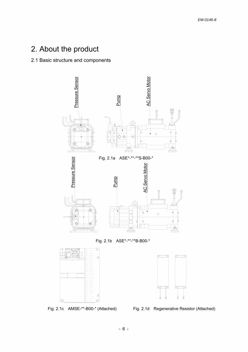
2. About the product 2.1 Basic structure and components
Fig. 2.1a ASE*-**-**S-B00-*
Fig. 2.1b ASE*-**-**B-B00-*
Fig. 2.1c AMSE-**-B00-* (Attached) Fig. 2.1d Regenerative Resistor (Attached)
Pre
ssur
e S
enso
r P
ump
AC S
ervo
Mot
or
Pre
ssur
e S
enso
r Pum
p
AC S
ervo
Mot
or

EM-0146-8
- - 7
2.2 Basic system configuration The product is a compact and energy-saving hydraulic device comprised of an AC servo motor and a piston pump. This unit can be combined with the dedicated controller to facilitate the configuration of a speed and pressure control system.
Fig. 2.2a Basic System Configuration
2.3 Control system The control system provides the variable control of pump discharge pressure and flow by controlling the AC servo motor speed according to externally input pressure and flow commands. Pressure control is based on closed-loop control with the feedback of signals from the pressure sensor built in the pump unit.
Fig. 2.3a Control System
The components in the dashed line box are supplied with the product (excluding cables).
M
AMSE Controller
Reg
ener
ativ
e
Res
isto
r
Main System’s
Controller
Sequence Signal
Analog I/O
Pressure Sensor M
Flow Command
Pressure Command
AMSE

EM-0146-8
- - 8
2.4 Model number designation 2.4.1 ASE model
Fig. 2.4a Model Number Designation for ASE
2.4.2 Components
Table 2.4a Combination of Components
ASE3-4 AA –G 80 S -B 00-31 Series No. Design No. ASE3: CA37-Z406 ASE3/5: 31 ASE10: 21 ASE5: CA56-Z406 Parameter No. ASE10: CA100-Z406 00: Standard Input Voltage Function Selection 4: AC 400 V B: Combination use (Single Use Allowed) No symbol: AC 200 V
Port Direction Power Capacity S: Horizontal B: VerticalAA: 11 kW (AMSE-*AA-: 15 kW) BZ: 20 kW (AMSE-*BB-: 22 kW) Max. Flow CE: 35 kW (AMSE-*DE-: 45 kW) 80: 80.8 L/min
130: 132.7 L/min Max. Operating Press 200: 205.4 L/min G: 17.5 MPa
Model AMSE Controller Model Brake Unit Regenerative Resistor Model
4AA- AMSE-4AE-B00-10 ―
FR-ABR-H15K (indicated on the package)
FR-ABR-15K (indicated on the body)
ASE3-
2AA- AMSE-2AE-B00-10 ― FR-ABR-15K
4BZ- AMSE-4BB-B00-11 ― FR-ABR-H22K × 2 ASE5- 2BZ- AMSE-2BB-B00-11 ― FR-ABR-22K × 2
ASE10- 4CE- AMSE-4DE-B00-10 FR-BU2-H30K-04 FR-ABR-H11K-03 × 3

EM-0146-8
- - 9
2.5 Specifications Table 2.5a Specifications
Model ASE3-*AA-G80*- ASE5-*BZ-G130*- ASE10-4CE-G200*-
Max. Flow L/min 80.8 132.7 205.4 Min. Controlled Flow 2 %
Hysteresis 1 % or less Repeatability 1 % or less
Flow
Con
trol
Input Signal Voltage *1 0 to 6.25 V 0 to 5.75V 0 to 5.00V
Pres. Adj. Range MPa 0.1 to 17.5
Hysteresis 1 % or less *2
Repeatability 1 % or less *2
Pre
s. C
ontro
l
Input Signal Voltage *1 0 to 5.0 V
Atmosphere Indoors (no direct sunlight) No corrosive gas, flammable gas, oil mist, or dust.
Altitude 1000 m or less above sea level
Ambient Temp. 0 to 40 °C (no freezing) Storage *3
Ambient Humidity 80 %RH or less (no condensation) *1 Default value (allowable maximum input signal voltage: up to 10 V). *2 Pressure control accuracy depends on system tuning; this value is for reference. *3 The storage temperature is different from the ambient temperature during operation.
Table 2.5b ASE (Pump) Specifications
Table 2.5c AC Servo Motor Specifications
Model ASE*-**-***-
Operating Pres. 0.1 to 17.5 MPa
Rotational Direction Clockwise when viewed from the servo motor
Hydraulic Fluid Petroleum based fluid equivalent to ISO VG32 or 46
Viscosity 20 to 400 mm2/s
Fluid Temp. 0 to 60 °C
Model ASE*-**-***-
Insulation Class Class F
Cooling System Totally-enclosed forced-cooling
Protection IP44 (except for the shaft through portion)
Ambient Temp. 0 to 40 °C (no freezing)
Ambient Humidity 80 %RH or less (no condensation)
Env
ironm
enta
l C
ondi
tion
Vibration 24.5 m/s2 or less(When the motor stops, reduce the allowable value to less than one-half.)
Fan Power Voltage/Frequency Single-phase, AC 180 to 220 V, 50/60 Hz

EM-0146-8
- - 10
Table 2.5d AMSE Controller Specifications
Table 2.5e Facilities
Model AMSE-4AE- (AMSE-2AE-)
AMSE-4BB- (AMSE-2BB-) AMSE-4DE-
Voltage 3-phase, AC 380 to 480 V, 50/60 Hz (3-phase, AC 200 to 220 V/50 Hz, AC 200 to 240 V/60 Hz)
Permissible Voltage Fluctuation
3-phase, AC 323 to 528 V, 50/60 Hz (3-phase, AC 170 to 242 V/50 Hz, AC 170 to 264 V/60 Hz)
Mai
n C
ircui
t P
ower
Permissible Frequency Fluctuation ± 5 % or less
Command Signal Input Voltage 0 to 10 V DC (Pressure/flow command input)
Command Signal Input Impedance 10 kΩ
Monitor Output Voltage 1ch. 0 to 10 V DC (The output can be changed by parameters.)
Sequence Input Signal 12chs. Photocoupler input (current limiting resistance: 4.7 KΩ) Power voltage: DC 21 to 27 V, short-circuited current: 4 to 6 mA2chs. Relay output (contact capacity: AC 230 or DC 30 V, 0.3 A)
Inte
rface
Sequence Output Signal 5chs. Open collector output (permissible load: DC 24 V, 0.1 A) Cooling System Forced fan cooling, enclosed (IP20)
Ambient Temp. 0 to 50 °C (no freezing) Ambient Humidity 90 %RH or less (no condensation) Environmental
Condition Vibration 5.9 m/s2 or less
Protective Functions
Overcurrent Regenerative overvoltage AMSE controller overloadMotor overload Fin overheat Instantaneous power failure Undervoltage Input open-phase Output open-phase Stall prevention Ground fault overcurrent on the output side Communication option error Parameter memory device error CPU error Operation panel power short circuit DC 24 power output short circuit Inrush current limiting circuit error Analog input error Fan fault Electronic thermal pre-alarm Dynamic brake pre-alarm PU stop Brake transistor error Parameter write error Copy operation error Operation panel lockParameter copy alarm Communication error USB communication error Internal circuit error Maintenance signal output Error Hydraulic control board error Hydraulic control board warning
ASE3- ASE5- ASE10- Model 4AA- AA- 4BZ- BZ- CE-
Power Capacity 27 kVA 28 kVA 41 kVA 80 kVA
Current Breaker
100 A frame/60 A
225 A frame/125 A
100 A frame/100 A
225 A frame /175 A
225 A frame /175 A
Electromagnetic Switch N25 N50 N30 N80 N80
EM-0146-8
- - 11
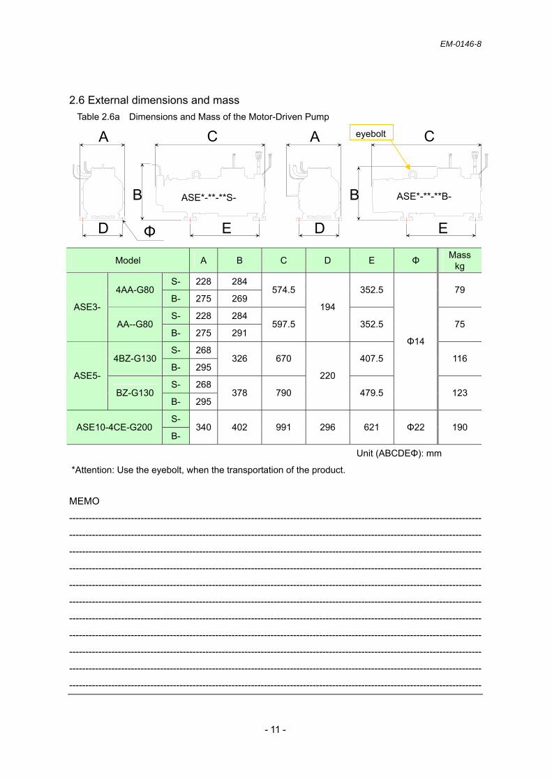
2.6 External dimensions and mass Table 2.6a Dimensions and Mass of the Motor-Driven Pump
MEMO
-------------------------------------------------------------------------------------------------------------------------------
-------------------------------------------------------------------------------------------------------------------------------
-------------------------------------------------------------------------------------------------------------------------------
-------------------------------------------------------------------------------------------------------------------------------
-------------------------------------------------------------------------------------------------------------------------------
-------------------------------------------------------------------------------------------------------------------------------
-------------------------------------------------------------------------------------------------------------------------------
-------------------------------------------------------------------------------------------------------------------------------
-------------------------------------------------------------------------------------------------------------------------------
-------------------------------------------------------------------------------------------------------------------------------
-------------------------------------------------------------------------------------------------------------------------------
Model A B C D E Φ Mass kg
S- 228 284 4AA-G80
B- 275 269 574.5 352.5 79
S- 228 284 ASE3-
AA--G80 B- 275 291
597.5
194
352.5 75
S- 268 4BZ-G130
B- 295 326 670 407.5 116
S- 268 ASE5-
BZ-G130 B- 295
378 790
220
479.5
Φ14
123
S- ASE10-4CE-G200
B- 340 402 991 296 621 Φ22 190
Unit (ABCDEΦ): mm
*Attention: Use the eyebolt, when the transportation of the product.
Φ
A
B
C A
B
C
ASE*-**-**S- ASE*-**-**B-
D E D E
eyebolt

EM-0146-8
- - 12
Table 2.6b Dimensions and Mass of
the AMSE Controller and Regenerative Resistor
AMSE Controller
Regenerative Resistor
Brake Unit
G I HK
F J
Φ
Model A B C D E Φ Mass kg
AMSE-4AE- 300 220 190 285 195 Φ6 7.5 AMSE-2AE- 14.0 AMSE-4BB- AMSE-2BB-
400 250 190 380 230 Φ10 13.0
AMSE-4DE- 550 435 250 525 380 Φ12 35.0 Unit (ABCDEΦ): mm
Regenerative Resistor F G H I J K Φ Mass
kg FR-ABR-15K 300 285 2.2/piece
FR-ABR-H22K 450 435 3.6/piece FR-ABR-H11K-03 400 3.2/piece
FR-ABR-22K
100
400
700 50 80.5 385
Φ5.3
3.0/piece Unit (FGHIJKΦ): mm
* ASE10-4CE- Attached
Unit: mm 118
128
96 108
Φ5
5130
A D
BE Φ C

EM-0146-8
- - 13
2.7 Interface 2.7.1 Parts of the AMSE controller (with the cover installed)
Fig. 2.7a Top Face of the AMSE Controller
2.7.2 Removal of the AMSE controller cover Note) It is dangerous to remove the cover with the controller powered on. Double-check that
the controller power is turned off. Before starting wiring work, remove the cover in the following steps. When mounting the cover, take the reverse steps.
Fig. 2.7b Removal of the Cover
Lightly pressing the locations indicated by “ → ,” lift the cover in the direction of “→.”
Use a screwdriver to loosen the two bolts fixing the cover. The bolts are designed to remain attached to the cover.
USB Port (Type B) Allows simple monitoring or collective parameter setting with ASE-dedicated software on a PC. This port is not used for manual adjustment.
Operation Panel Performs parameter setting or status change/display.
Cover Fixing Bolt To perform wiring work, the cover must be opened by loosening the bolts.

EM-0146-8
- - 14
2.7.3 Parts of the AMSE controller (internal parts)
Fig. 2.7c Parts of the AMSE Controller
Control Circuit Terminals Connect wiring for I/O signals (see the tables below).
- Table 2.7a Sequence Input - Table 2.7b Analog I/O - Table 2.7c Error Output - Table 2.7d Sequence Output - Table 2.7e Others
* The terminal arrangement is also shown on the back side of the upper cover.
USB Connector (Type B)
Operation Panel (PU) Power Terminal
×: Not used. Do not connect wiring.
Sensor Terminals Connect wiring for the pressure sensor and thermistor. - See Table 2.7f.
Combination Use Setting Area Configured when operating the unit in combination use. - See 8 Combination use.
Main Circuit Terminals Connect wiring for AC power input, motor output, grounding, and regenerative resistors. - See Table 2.7g. * The configuration varies depending on the model.
EMC Filter On/Off Connector This system has a capacitive filter and zero-phase reactor. - See 7.3.
Used for the input of control power separate from the main circuit power. - See 2.7.7.

EM-0146-8
- - 15
2.7.4 Control circuit terminals
Table 2.7a Sequence Input
Type Symbol Name Function/Use Rating
STF Forward Rotation Start (Servo-on)
“ON”: Forward rotation command “OFF”: Stop command
STR Reverse Rotation Start
<Not used.> “ON”: Reverse rotation command “OFF”: Stop command
STOP Reserved Disabled.
RH Control Code x 1
RM Control Code x 2
Switches the gain according to the load condition variable for each process.
Input Signal RH RM Control Code
OFF OFF No. 0 control parameter ON OFF No. 1 control parameter OFF ON No. 2L control parameter ON ON No. 3 control parameter
JOG Reserved Disabled. RT Reserved Disabled.
MRS Emergency Stop “OFF”: Emergency stop “ON”: Emergency stop reset
RES Reset Resets an alarm. AU Reserved Disabled. CS Reserved Disabled.
Input resistance: 4.7 KΩ
Open-circuit voltage: DC 21 to 27 V
Short-circuit voltage: DC 4 to 6 mA
SD Contact Input Common
Common terminal for contact input terminals. Note) This terminal is insulated from Terminals
“5” and “SE.” -
Con
tact
Inpu
t
PC DC 24 V Power Output
This terminal can be used to supply DC 24 V, 0.1 A power.
Power voltage range: DC 20 to 28 V Permissible load current: 100 mA
Servo-on
Control Code × 2
Control Code × 1
AMSE
STF
SD
RH
RM
MRS
RES
Customer’s Scope of Work
Fig. 2.7d Simplified Wiring Diagram
When the servo is turned "ON", there is a possibility that the device moves spontaneously. Therefore, the preventive measure is required to secure the servo is not turned "ON" until confirm the safety of device. If the device moves spontaneously, there is a a risk of human death or severe injury.
WARNING
Reset
Emergency Stop

EM-0146-8
- - 16
Table 2.7b Analog I/O Type Symbol Name Function/Use Rating
10E DC 10 V Power Output
This terminal can be used to supply DC 10 V, 10 mA power.
DC 10 ± 0.4 V Permissible load current: 10mA
10 DC 5 V Power Output
This terminal can be used to supply DC 5 V, 10 mA power.
DC 5.2 ± 0.2 VPermissible load current: 10 mA
2 Pressure Command Voltage
A voltage of DC 0 to + 5 V (max. 10 V) is applied between Terminals “2” and “5.” The span of the command voltage is set by the parameter below.
Parameter No. Rated Pressure P460 Default: 175 [× 0.1 MPa/5 V]
* See “Table 6.7n” for setting.
4 Flow Command Voltage
A voltage of DC 0 to + 5 V (max. 10 V) is applied between Terminals “4” and “5.” The span of the command voltage is set by the parameter below.
Parameter No. Rated Flow Rate P461 Default: 2000 [rpm/5 V]
* See “Table 6.7n” for setting.
Input resistance: 10 ± 1 kΩ Permissible voltage: DC 20 V
5 Control Common Common terminal for command voltage and monitoring voltage. -
1 Reserved Not used. Do not connect wiring. - Flow
/Pre
ssur
e S
ettin
g
AM General Monitor
Selects and outputs monitoring items. The setting parameter “P463: AM Monitoring Output Item Selection” can be used to check the output of the following items.
Setting Output Name Symbol 0 Motor Speed Command Vref 1 Pressure Command PIN 2 Flow Command QIN 3 Pressure Sensor Monitor SMP
4 Motor Speed Monitor (Calculated Value) SMN
5 Motor Torque TRQ
6 Electronic Thermal Load Factor SMF
Output signal: DC 0 to 10 V Permissible load current: 1 mA Load impedance: 10 kΩ or more Resolution: 8 bits
Table 2.7c Error Output
Type Symbol Name Function/Use Rating
A1 Warning Output - Contact B
B1 Warning Output - Contact A
C1 Warning Output - Common
This contact output indicates that the AMSE controller’s warning function is activated. Warning: Continuity between B and C
(discontinuity between A and C) Normal: Discontinuity between B and C
(continuity between A and C)
A2 Alarm Output - Contact B
B2 Alarm Output - Contact A
Rel
ay C
onta
ct O
utpu
t
C2 Alarm Output - Common
This contact output indicates that the AMSE controller’s alarm function is activated to stop the output. Warning: Continuity between B and C
(discontinuity between A and C) Normal: Discontinuity between B and C
(continuity between A and C)
Contact capacity: AC 230 V, 0.3 A DC 30 V, 0.3 A

EM-0146-8
- - 17
Table 2.7d Sequence Output Type Symbol Name Function/Use Rating
RUN Operation Ready Turned “on” when STF/STR is “on” and the unit is ready to run with a flow/pressure command.
0L Swash Plate Angle Large Not used.
IPF Alarm Code - 0 SU Alarm Code - 1
FU Alarm Code - 2
Outputs a 3-bit code to describe an alarm when the AMSE controller’s protection function is activated to stop the output.
Output Terminal Symbol
FU SU IPFDescription
OFF OFF OFF
Parameter memory device error
CPU error Inrush current limiting
circuit error Analog input error Option error Communication error Internal circuit error DC 24 power output short
circuit Operation panel power
short circuit USB communication error Hydraulic control board
error
OFF OFF ON Regenerative overvoltage Brake transistor error
detection
OFF ON OFF Undervoltage Instantaneous power
failure
OFF ON ON
AMSE controller overload Motor overload Fin overheat Stall prevention
ON OFF OFF Overcurrent Ground fault overcurrent
on the output side
ON ON ON Input open-phase Output open-phase PU disconnection
Permissible load: DC 24 V, 0.1 A (max. DC 27 V) * Max. voltage drop with “on”:2.8 V O
pen
Col
lect
or O
utpu
t
SE Open Collector Output Common
Common terminals for RUN, OL, IPF, SU, and FU. -
Table 2.7e Others Type Symbol Name Function/Use Rating
FM - Not used. Do not connect wiring. -
EM-0146-8
- - 18
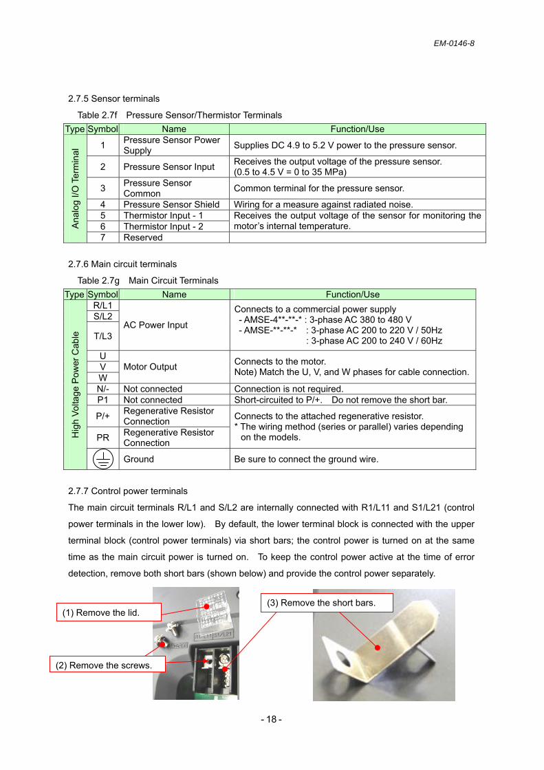
2.7.5 Sensor terminals
Table 2.7f Pressure Sensor/Thermistor Terminals Type Symbol Name Function/Use
1 Pressure Sensor Power Supply Supplies DC 4.9 to 5.2 V power to the pressure sensor.
2 Pressure Sensor Input Receives the output voltage of the pressure sensor. (0.5 to 4.5 V = 0 to 35 MPa)
3 Pressure Sensor Common Common terminal for the pressure sensor.
4 Pressure Sensor Shield Wiring for a measure against radiated noise. 5 Thermistor Input - 1 6 Thermistor Input - 2
Receives the output voltage of the sensor for monitoring the motor’s internal temperature. A
nalo
g I/O
Ter
min
al
7 Reserved 2.7.6 Main circuit terminals
Table 2.7g Main Circuit Terminals Type Symbol Name Function/Use
R/L1 S/L2
T/L3 AC Power Input
Connects to a commercial power supply - AMSE-4**-**-* : 3-phase AC 380 to 480 V - AMSE-**-**-* : 3-phase AC 200 to 220 V / 50Hz
: 3-phase AC 200 to 240 V / 60Hz U V W
Motor Output Connects to the motor. Note) Match the U, V, and W phases for cable connection.
N/- Not connected Connection is not required. P1 Not connected Short-circuited to P/+. Do not remove the short bar.
P/+ Regenerative Resistor Connection
PR Regenerative Resistor Connection
Connects to the attached regenerative resistor. * The wiring method (series or parallel) varies depending
on the models. Hig
h Vo
ltage
Pow
er C
able
Ground Be sure to connect the ground wire.
2.7.7 Control power terminals
The main circuit terminals R/L1 and S/L2 are internally connected with R1/L11 and S1/L21 (control
power terminals in the lower low). By default, the lower terminal block is connected with the upper
terminal block (control power terminals) via short bars; the control power is turned on at the same
time as the main circuit power is turned on. To keep the control power active at the time of error
detection, remove both short bars (shown below) and provide the control power separately.
(1) Remove the lid.
(2) Remove the screws.
(3) Remove the short bars.

EM-0146-8
- - 19
3. Installation of the ASE pump unit 3.1 Tools for installation
Prepare the tool listed below.
Table 3.1a Tool for Pump Installation
Table 3.1b Tool for Suction Pipe Flange Connection
Table 3.1c Tool for Discharge Pipe Flange Connection
Table 3.1d Filling Port
3.2 Relocation of the ASE pump unit Take great care not to drop, knock over, or damage the product during transport.
Never lift or carry the product in an incorrect posture. Pinching of hands or backache may
occur depending on the product mass or the posture of the worker.
Do not step on or put any heavy object on the product. Doing so may result in damage to
the product/equipment or injury from slipping/falling.
Model Tool (Size)
ASE3/5/10- Allen wrench (width across flats: 10 mm)
Model Tool (Size)
ASE3/5/10- Allen wrench (width across flats: 8 mm)
Model Tool (Size)
ASE3/5/10- Wrench (width across flats: 22 mm)
CAUTION
Model Tool (Size)
ASE3/5- Wrench (width across flats: 19 mm)
ASE10- Wrench (width across flats: 22 mm)

EM-0146-8
- - 20
3.3 Preparation for installation a) Before starting installation work, clean and dust the working area, hands, and clothing to prevent
foreign matter from entering the product/equipment. b) Remove the protective plug from the port and the protective plates from the port flange mounting
surface. When removing the plates, be careful not to damage the mounting surface.
Fig. 3.3a Removal of the Protective Plug and Plates c) Check for critical scratches on the O-ring sealing surface of each port and the port flange mounting
surface. If any scratch is found, eliminate it by mending the mounting surface. If a critical scratch that cannot be mended is found, contact our customer support.
d) Clean the O-ring sealing surface of each port and the port flange mounting surface to ensure that
there is no foreign matter, such as metal debris and lint from waste cloth. e) Check for critical scratches on the O-ring mounting surface of the pipe flange and check that the
O-ring is properly mounted in the groove. If required, mount it in the groove correctly.
Any critical scratch on the mounting surface may cause fluid leakage, resulting in a major accident.
Improper mounting of the O-rings may cause damage to them or outflow of hydraulic fluid, resulting in a major accident.
CAUTION
CAUTION

EM-0146-8
- - 21
3.4 Installation of the ASE pump unit 3.4.1 Installation position
- Install the unit with the filling port facing upward. - Bolt the unit securely using the mounting holes on the bracket.
: Bolt/plain washer location
Fig. 3.4a Installation Example
3.4.2 Bolting
Screw in the bolts listed below gradually and evenly. Note) Use the washers to prevent the bolts from loosening. Table 3.4a Bolt Size and Tightening Torque
Use the specified number of bolts of the same material/strength grade and apply the specified tightening torque. Failure to do so may cause damage to the bolts or outflow of hydraulic fluid, resulting in a major accident.
150 mm
WARNING
Model Bolt Size Quantity Tightening Torque N•m
ASE3/5-
JIS B1180 Hexagon Head Bolt
M12 (Strength Grade: 6.8 or more)
4 50 to 55
ASE10-
JIS B 1180 Hexagon Head Bolt
M20 (Strength Grade: 6.8 or more)
4 232 to 256
Improper mounting condition of foot blacket, may increase noise level during operation.In such case, use the anti-vibration rubber or acoustic absorbent to cover the foot blacket and take apporpriate measures.Continuing the operation under such condition may result in human injury.
CAUTION

EM-0146-8
- - 22
3.5 Piping 3.5.1 Drain piping
- For piping, see the table below. - Be sure that the pipe end is submerged in fluid. - Do not join the drain pipe to other return lines. Run it independently.
Table 3.5a Drain Pipe Size
Even when the condition above is met, install the piping in such a way that the steady state pressure in the housing is 0.1 MPa or less.
3.5.2 Suction piping
- For suction piping, use pipes of the following sizes.
Table 3.5b Suction Pipe Size
- Position the suction port 1 m or less above the fluid level. - When installing the pump in a position higher than the fluid level, avoid placing the suction pipe
and filter at a position higher than the pump port to prevent air accumulation in the suction line. - Keep the suction pressure at the pump inlet between - 16.7 kPa and + 50 kPa.
When the suction pressure exceeds the prescribed value, abnormal noise/vibration may occur. MEMO
-------------------------------------------------------------------------------------------------------------------------------
-------------------------------------------------------------------------------------------------------------------------------
-------------------------------------------------------------------------------------------------------------------------------
-------------------------------------------------------------------------------------------------------------------------------
-------------------------------------------------------------------------------------------------------------------------------
-------------------------------------------------------------------------------------------------------------------------------
-------------------------------------------------------------------------------------------------------------------------------
-------------------------------------------------------------------------------------------------------------------------------
-------------------------------------------------------------------------------------------------------------------------------
-------------------------------------------------------------------------------------------------------------------------------
-------------------------------------------------------------------------------------------------------------------------------
Model Joint Size Pipe Bore Pipe Length ASE3/5- 1/2 (Bore: Φ12 or more) Φ12 or more ASE10- 3/4 (Bore: Φ19 or more) Φ19 or more
1000 mm or less
Model Nominal Diameter ASE3- 1 1/4 ASE5- 1 1/2 ASE10- 2 1/2

EM-0146-8
- - 23
3.5.3 Pipe tightening
The pipe tightening torque is shown in Table 3.5c.
Table 3.5c Screw Size and Tightening Torque
Model Screw Size Tightening Torque[Nm]
Discharge Pipe ASE3/5/10- Port Flange Screw: JIS B1176
Hexagon Socket Head Cap ScrewM10 (Strength Grade: 12.9)
61 to 74
Suction Pipe ASE3/5/10- Port Flange Screw: JIS B1176
Hexagon Socket Head Cap ScrewM12 (Strength Grade: 12.9)
104 to 127
ASE3/5- Rc1/2 52 to 95 Drain Pipe
ASE10- Rc3/4 90 to 165
When using four screws for the suction pipe flange, tighten them gradually and evenly in the order shown by the numbers 1 to 4 in Fig. 3.5a and repeat this cycle two or three times.
When using steel pipes, they may place excessive load on the motor-driven pump unit, resulting in noise. If there is a possibility that steel pipes may place such load on the unit, use rubber hoses.
Apply the pipe tightening torque as specified. Failure to do so may cause damage to the screws or outflow of hydraulic fluid, resulting in a major accident.
Do not tighten the screws with the O-rings mounted improperly. Doing so may cause damage to the O-rings or outflow of hydraulic fluid, resulting in a major accident.
WARNING
WARNING
Fig. 3.5a Screw Tightening

EM-0146-8
- - 24
4. Installation of the AMSE controller 4.1 Preparation for installation
4.1.1 Installation standards (the values below indicate minimum clearances.)
Fig. 4.1a Installation Standards
4.1.2 Installation orientation Install the AMSE controller vertically on the wall with its front face (with the operator panel) facing toward the operator. 4.1.3 Cooling With reference to Fig. 4.1a, leave enough space around the AMSE controller to allow cooling by the fan and natural convection. The cooling fan is required to keep the temperature in the control panel uniform so that the ambient temperature around the AMSE controller does not locally increase. 4.1.4 Environmental condition in the control panel Ambient temperature around the AMSE controller: 0 to 50 °C Humidity: 90 %RH (relative humidity) or less Vibration: 5.9 m/s2 or less No freezing or condensation is permitted. Operation at an ambient temperature of 45 °C or less is recommended to ensure operational reliability for a long term.
The AMSE controller is fan-cooled. Be sure to observe the following installation standards and pay attention to the circulation of air.
CAUTION
100 mm
50 mm50 mm
100 mm
50 mm
100 mm
100 mm
50 mm 50 mm
FAN
- Single Unit Installation - Multiple Unit Installation
EM-0146-8
- - 25
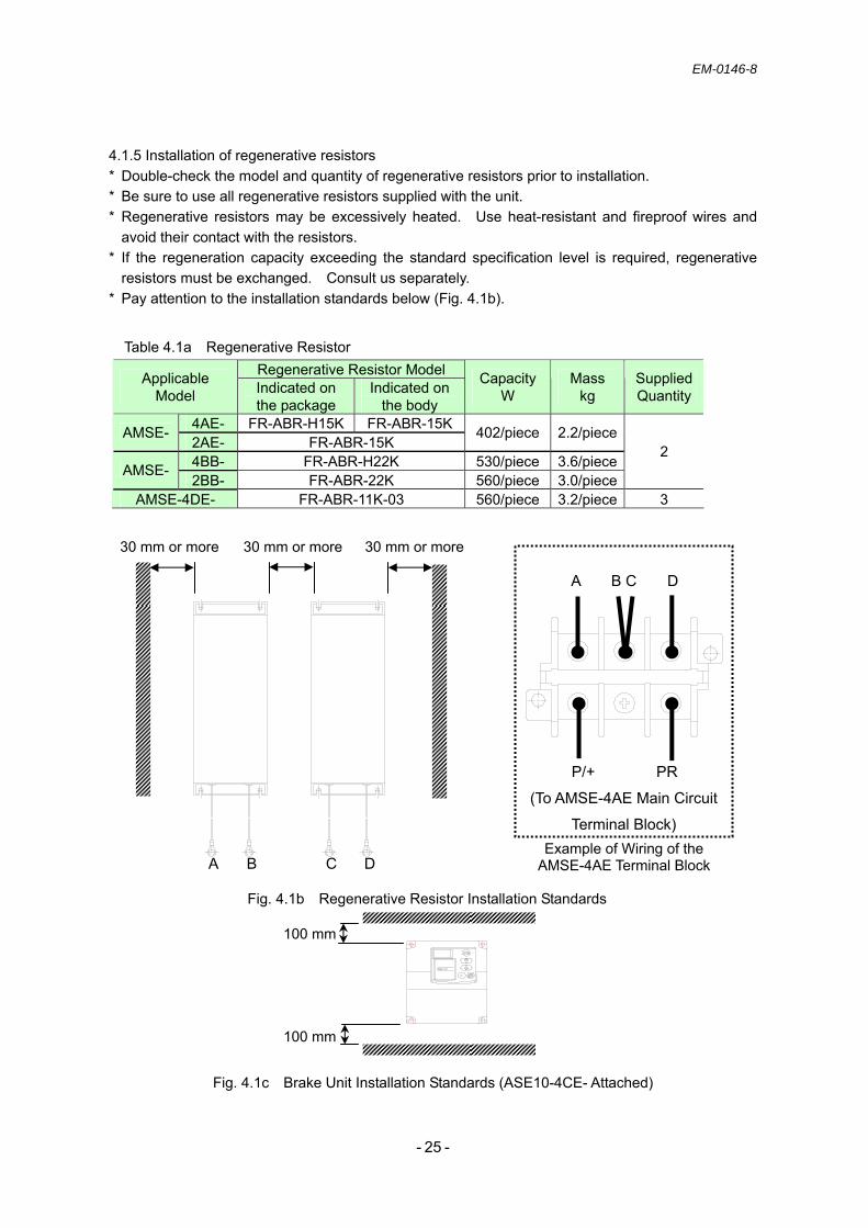
4.1.5 Installation of regenerative resistors * Double-check the model and quantity of regenerative resistors prior to installation. * Be sure to use all regenerative resistors supplied with the unit. * Regenerative resistors may be excessively heated. Use heat-resistant and fireproof wires and
avoid their contact with the resistors. * If the regeneration capacity exceeding the standard specification level is required, regenerative
resistors must be exchanged. Consult us separately. * Pay attention to the installation standards below (Fig. 4.1b).
Table 4.1a Regenerative Resistor
Fig. 4.1b Regenerative Resistor Installation Standards
Fig. 4.1c Brake Unit Installation Standards (ASE10-4CE- Attached)
30 mm or more 30 mm or more30 mm or more
A B C D Example of Wiring of the
AMSE-4AE Terminal Block
A B C D
P/+ PR
(To AMSE-4AE Main Circuit
Terminal Block)
Regenerative Resistor Model Applicable Model Indicated on
the package Indicated on
the body
Capacity W
Mass kg
Supplied Quantity
4AE- FR-ABR-H15K FR-ABR-15KAMSE- 2AE- FR-ABR-15K
402/piece 2.2/piece
4BB- FR-ABR-H22K 530/piece 3.6/piece AMSE- 2BB- FR-ABR-22K 560/piece 3.0/piece
2
AMSE-4DE- FR-ABR-11K-03 560/piece 3.2/piece 3
100 mm
100 mm

EM-0146-8
- - 26
4.2 Terminal wiring diagram
Fig. 4.2a Wiring Diagram
Control Circuit
Terminals
The wiring method varies depending on
the models. See 4.3.
Main Circuit Terminals
NFB MC
Regenerative Resistor
Warning Output
Alarm Output
Sensor Terminals
Pressure Sensor
Forward Rotation Start Control Code x1
Control Code x2
Emergency Stop
Reset
Contact Input Common
DC 24 V Power Output
MU V W
5 6 7
10E 10 2 4 5 AM A1 B1 C1 A2 B2 C2
EMC Filter
ON
OFF
Combination UseSetting Area
PU Terminal
USB Terminal
SW1: No. 3 is “ON” forsingle operation.
SW2: “0” is set for single operation.
Operation Ready
Alarm Code - 0
Alarm Code - 1
Alarm Code - 2
Open Collector Output Common
Used to separate the control power from the main power. See 2.2.7.
R/L1 P1 P/+ PR N/- S/L2 T/L3
R1/L11 S1/L21 1 2 3 4 STF RH RM MRS RES SD PC RUN IPF SU FU SE
DC 10 V Power Output
DC 5 V Power Output
Pressure Command Voltage
Flow Command Voltage
Control Common
General Monitor
OHS1
OHS2

EM-0146-8
- - 27
4.3 Wiring of regenerative resistors
AMSE-4AE- AMSE-AE/BB/4BB-
AMSE-4DE-
Fig. 4.3a Wiring Diagram of Regenerative Resistors
P1 P/+ PR N/-
Reg
ener
ativ
e R
esis
tor
Reg
ener
ativ
e R
esis
tor
Reg
ener
ativ
e R
esis
tor
Reg
ener
ativ
e R
esis
tor
P1 P/+ PR N/-
Series wiring Parallel wiring
Regenerative Resistor
Regenerative Resistor
Regenerative Resistor
N/- P/+ PR
Brake Unit (FR-BU2-H30K-04)
P1 P/+ PR N/-
Parallel wiring

EM-0146-8
- - 28
4.4 Wiring type
Table 4.4a Main Circuit Terminal Wiring Types
Table 4.4b Control Circuit Terminal/Sensor Terminal Wiring Types
MEMO -------------------------------------------------------------------------------------------------------------------------------
-------------------------------------------------------------------------------------------------------------------------------
-------------------------------------------------------------------------------------------------------------------------------
-------------------------------------------------------------------------------------------------------------------------------
Item Control Circuit Terminal Block Sensor Terminal Block
Wire (mm2) 0.75 to 2.1 (AWG18 to 14) 0.5 to 1.3 (AWG20 to 16) Screw Size M3.5 Push lock type AMSE- Tightening
Torque 1.2 N・m -
Main Circuit Terminal Block
AMSE- Item AC Power Input (R/L1, S/L2, T/L3)
Motor Output
(U, V, W)
Ground Wire
Regenerative Resistor
(P/+, N/-, -PR) Wire (mm2) 8 (AWG8) 2.1 (AWG14) Screw Size M5 4AE- Tightening
Torque 2.5 N・m
Wire (mm2) 22 (AWG4) 14 (AWG6) 2.1 (AWG14) Screw Size M6 2AE- Tightening
Torque 4.4 N・m
Wire (mm2) 14 (AWG6) 2.1 (AWG14) Screw Size M6 4BB- Tightening
Torque 4.4 N・m
Wire (mm2) 38 (AWG2) 22 (AWG2) 2.1 (AWG14) Screw Size M8 2BB- Tightening
Torque 7.8 N・m
Wire (mm2) 38 (AWG1) 38 (AWG2) 3.5 (AWG12) Screw Size M8 4DE Tightening
Torque 7.8 N・m
Wire (mm2) - 3.5 (AWG12) Screw Size - M4
FR-BU2
-H30K-0
4 Tightening
Torque - 1.5 N・m
EM-0146-8
- - 29
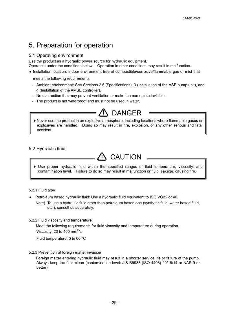
5. Preparation for operation 5.1 Operating environment Use the product as a hydraulic power source for hydraulic equipment. Operate it under the conditions below. Operation in other conditions may result in malfunction. Installation location: Indoor environment free of combustible/corrosive/flammable gas or mist that
meets the following requirements.
- Ambient environment: See Sections 2.5 (Specifications), 3 (Installation of the ASE pump unit), and 4 (Installation of the AMSE controller).
- No obstruction that may prevent ventilation or make the nameplate invisible. - The product is not waterproof and must not be used in water.
5.2 Hydraulic fluid
5.2.1 Fluid type
Petroleum based hydraulic fluid: Use a hydraulic fluid equivalent to ISO VG32 or 46. Note) To use a hydraulic fluid other than petroleum based one (synthetic fluid, water based fluid,
etc.), consult us separately.
5.2.2 Fluid viscosity and temperature Meet the following requirements for fluid viscosity and temperature during operation. Viscosity: 20 to 400 mm2/s
Fluid temperature: 0 to 60 °C
5.2.3 Prevention of foreign matter invasion Foreign matter entering hydraulic fluid may result in a shorter service life or failure of the pump. Always keep the fluid clean (contamination level: JIS B9933 (ISO 4406) 20/18/14 or NAS 9 or better).
♦ Never use the product in an explosive atmosphere, including locations where flammable gases or explosives are handled. Doing so may result in fire, explosion, or any other serious and fatal accident.
DANGER
♦ Use proper hydraulic fluid within the specified ranges of fluid temperature, viscosity, and contamination level. Failure to do so may result in malfunction or fluid leakage, causing fire.
CAUTION

EM-0146-8
- - 30
5.3 Operation of the ASE pump unit
Note) - Do not join the drain line to other return lines. Doing so may result in malfunction or failure.
- Long-time operation with reverse rotation may cause pump seizing or damage to the parts. - Do not increase the pressure setting before the unit starts normal operation. Doing so may
result in pressure oscillation or abnormal noise. MEMO -------------------------------------------------------------------------------------------------------------------------------
-------------------------------------------------------------------------------------------------------------------------------
-------------------------------------------------------------------------------------------------------------------------------
-------------------------------------------------------------------------------------------------------------------------------
-------------------------------------------------------------------------------------------------------------------------------
------------------------------------------------------------------------------------------------------------------------------
-------------------------------------------------------------------------------------------------------------------------------
-------------------------------------------------------------------------------------------------------------------------------
-------------------------------------------------------------------------------------------------------------------------------
-------------------------------------------------------------------------------------------------------------------------------
-------------------------------------------------------------------------------------------------------------------------------
-------------------------------------------------------------------------------------------------------------------------------
-------------------------------------------------------------------------------------------------------------------------------
-------------------------------------------------------------------------------------------------------------------------------
-------------------------------------------------------------------------------------------------------------------------------
♦ Never fail to check fixation of units and piping before starting the motor-driven pump unit. Failure to do so may cause damage to the parts or outflow of hydraulic fluid, resulting in a major accident.
♦ When any abnormal condition (noise, fluid leakage, smoke, etc.) occurs, immediately stop operation and take appropriate measures. Continuing the operation under such conditions may result in an accident.
♦ Use the product as specified in the catalog, drawings, and specifications. Failure to do so may result in malfunction of or damage to the product, causing injury.
♦ Perform adjustment work while ensuring safety, e.g. keeping people away from the moving parts of equipment.
WARNING
CAUTION
EM-0146-8
- - 31
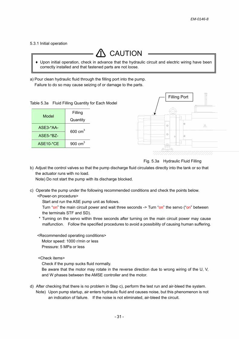
5.3.1 Initial operation
a) Pour clean hydraulic fluid through the filling port into the pump.
Failure to do so may cause seizing of or damage to the parts.
Table 5.3a Fluid Filling Quantity for Each Model
Fig. 5.3a Hydraulic Fluid Filling
b) Adjust the control valves so that the pump discharge fluid circulates directly into the tank or so that the actuator runs with no load. Note) Do not start the pump with its discharge blocked.
c) Operate the pump under the following recommended conditions and check the points below.
<Power-on procedure> Start and run the ASE pump unit as follows. Turn “on” the main circuit power and wait three seconds -> Turn “on” the servo (“on” between the terminals STF and SD).
* Turning on the servo within three seconds after turning on the main circuit power may cause malfunction. Follow the specified procedures to avoid a possibility of causing human suffering.
<Recommended operating conditions>
Motor speed: 1000 r/min or less Pressure: 5 MPa or less
<Check items>
Check if the pump sucks fluid normally. Be aware that the motor may rotate in the reverse direction due to wrong wiring of the U, V, and W phases between the AMSE controller and the motor.
d) After checking that there is no problem in Step c), perform the test run and air-bleed the system. Note) Upon pump startup, air enters hydraulic fluid and causes noise, but this phenomenon is not
an indication of failure. If the noise is not eliminated, air-bleed the circuit.
♦ Upon initial operation, check in advance that the hydraulic circuit and electric wiring have been correctly installed and that fastened parts are not loose.
注油口
CAUTION
Filling Port
Model Filling
Quantity
ASE3-*AA-
ASE5-*BZ- 600 cm3
ASE10-*CE 900 cm3

EM-0146-8
- - 32
6. Operation adjustment 6.1 Display and operation buttons
The AMSE controller allows status display and parameter setting for the ASE pump unit.
It has a 4-digit LED display to facilitate checking the output and parameters.
Fig. 6.1a Display and Operation Buttons
Layout of Buttons (For Manual Adjustment)
HzAV
MON P.RUN
PU EXT NET
REV FWD
PUEXT REV FWD
MODE SETSTOPRESET
HzAV
MON P.RUN
PU EXT NET
REV FWD
PUEXTPUEXT REVREV FWDFWD
MODEMODE SETSETSTOPRESETSTOPRESET
Monitor
No Function
Monitoring ModeNo Function
Rotational Direction
M Dial
Setting Buttons
Symbol Use Description PU/EXT <Not Used> REV <Not Used> FWD <Not Used>
Operating these buttons has no effect.
MODE Mode Switching Switches between the setting modes.
SET Setting Confirmation
Confirms settings. Pressing this button during operation switches the monitor display as follows. “Motor Speed” -> “Output Current” -> “Output Voltage”
STOP/RESET Alarm Reset Resets alarms. When the setting of the setting parameter “P_75” is changed, “STOP” (Motor Stop) is enabled.

EM-0146-8
- - 33
6.2 Communication cable <for setup by the manufacturer> - “USB2.0 Cable (Type AB)” is used as a communication cable. - For the ASE pump unit, monitoring and parameter adjustment can be performed by using
ASE-dedicated software. Manual parameter adjustment is unnecessary.
Fig. 6.2a Communication Cable Port
MEMO
-------------------------------------------------------------------------------------------------------------------------------
-------------------------------------------------------------------------------------------------------------------------------
-------------------------------------------------------------------------------------------------------------------------------
-------------------------------------------------------------------------------------------------------------------------------
-------------------------------------------------------------------------------------------------------------------------------
-------------------------------------------------------------------------------------------------------------------------------
-------------------------------------------------------------------------------------------------------------------------------
-------------------------------------------------------------------------------------------------------------------------------
-------------------------------------------------------------------------------------------------------------------------------
-------------------------------------------------------------------------------------------------------------------------------
-------------------------------------------------------------------------------------------------------------------------------
-------------------------------------------------------------------------------------------------------------------------------
Communication Cable Port
(When Using Dedicated Software) *1
*1 For the details of the dedicated software, consult us separately.

EM-0146-8
- - 34
6.3 Display transitions - At the time of power-on, the display appears as shown in Fig. 6.3a. - By default, the motor speed is displayed.
Fig. 6.3a Operation Panel
Fig. 6.3b Display Transition Chart
Hz A V
MON P.RUN
PU EXT NET
REV FWD
PU EXT REV FWD
MODE SET STOPRESET
MODE
SET
Press the “MODE” button.
Press the “SET” button.
Turn the “M Dial.”
Press the “M Dial.”
Frequency at Alarm Occurrence
Output Current at Alarm Occurrence
Output Voltage at Alarm Occurrence
Corresponding Previous Alarm7___
No AlarmE 0
Previous Alarm - 2
Previous Alarm - 1
Previous Alarm - 3
Previous Alarm - 4
Previous Alarm - 5
Previous Alarm - 6
Previous Alarm - 7
Previous Alarm - 8
Calibration Parameters
(C 1 to C15)
Setting Parameters
(P__1 to P991)
Calibration Parameters
(C---)
Parameter Clear
(Pr.CL)
All Parameter Clear
(ALLC)
Protected (Er.CL)
Parameter Copy (PCPY)
Alarm History E---
Setting Display P*** C---
Pr.CL ALLC Er.CL PCPY
Status
Output Current
Motor Speed
Alarm Display
Power-on Time at Alarm Occurrence
Set Value “P52” (Default:Output
Voltage)
Alarm
EM-0146-8
- - 35
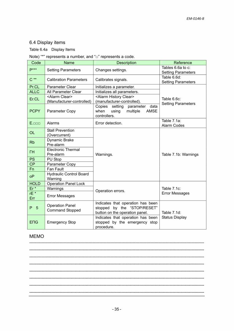
6.4 Display items Table 6.4a Display Items
Note) “*” represents a number, and “” represents a code. Code Name Description Reference
P*** Setting Parameters Changes settings. Tables 6.6a to c: Setting Parameters
C ** Calibration Parameters Calibrates signals. Table 6.6d: Setting Parameters
Pr.CL Parameter Clear Initializes a parameter. ALLC All Parameter Clear Initializes all parameters.
Er.CL <Alarm Clear> (Manufacturer-controlled)
<Alarm History Clear> (manufacturer-controlled).
PCPY Parameter Copy Copies setting parameter data when using multiple AMSE controllers.
Table 6.6c: Setting Parameters
E. Alarms Error detection. Table 7.1a: Alarm Codes
OL Stall Prevention (Overcurrent)
Rb Dynamic Brake Pre-alarm
ΓH Electronic Thermal Pre-alarm
PS PU Stop CP Parameter Copy Fn Fan Fault
oP Hydraulic Control Board Warning
Warnings. Table 7.1b: Warnings
HOLD Operation Panel Lock Er * Warnings rE * Err Error Messages
Operation errors. Table 7.1c: Error Messages
P 5 Operation Panel Command Stopped
Indicates that operation has been stopped by the “STOP/RESET” button on the operation panel.
EПG Emergency Stop Indicates that operation has been stopped by the emergency stop procedure.
Table 7.1d: Status Display
MEMO -------------------------------------------------------------------------------------------------------------------------------
-------------------------------------------------------------------------------------------------------------------------------
-------------------------------------------------------------------------------------------------------------------------------
-------------------------------------------------------------------------------------------------------------------------------
-------------------------------------------------------------------------------------------------------------------------------
-------------------------------------------------------------------------------------------------------------------------------
-------------------------------------------------------------------------------------------------------------------------------
-------------------------------------------------------------------------------------------------------------------------------

EM-0146-8
- - 36
6.5 Changing parameter settings
1) Turn on the power (the motor speed is displayed).
2) Enable the parameter setting mode.
A) Press the “MODE” button.
B) Check that “P” appears on the monitor.
C) Turn the “M Dial” to display the target parameter No, and then press the “SET” button. The currently set value is displayed.
D) Turn the “M Dial” to change the value, and then press the “SET” button. The parameter No. and the set value are displayed alternately to indicate that the setting has been confirmed.
E) Press the “MODE” button twice to return to the initial display.
When “P” is not displayed, turn the “M Dial” until “P” appears.
Hz A V
MON P.RUN
PU EXT NET
REV FWD
MODE
MON P.RUN
PU EXT NET
REV FWD
Hz A V
SET
SET
EM-0146-8
- - 37
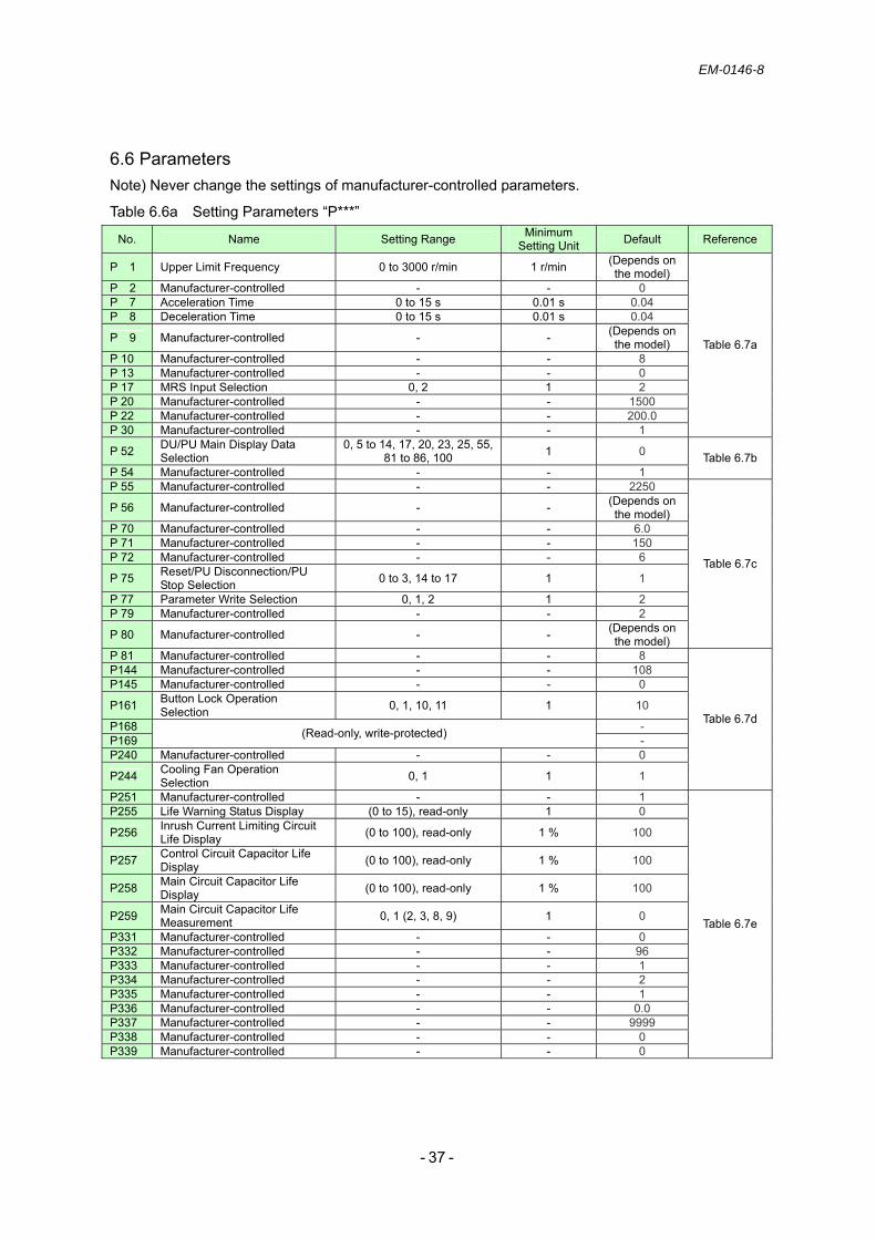
6.6 Parameters Note) Never change the settings of manufacturer-controlled parameters.
Table 6.6a Setting Parameters “P***”
No. Name Setting Range Minimum Setting Unit Default Reference
P 1 Upper Limit Frequency 0 to 3000 r/min 1 r/min (Depends on the model)
P 2 Manufacturer-controlled - - 0 P 7 Acceleration Time 0 to 15 s 0.01 s 0.04 P 8 Deceleration Time 0 to 15 s 0.01 s 0.04
P 9 Manufacturer-controlled - - (Depends on the model)
P 10 Manufacturer-controlled - - 8 P 13 Manufacturer-controlled - - 0 P 17 MRS Input Selection 0, 2 1 2 P 20 Manufacturer-controlled - - 1500 P 22 Manufacturer-controlled - - 200.0 P 30 Manufacturer-controlled - - 1
Table 6.7a
P 52 DU/PU Main Display Data Selection
0, 5 to 14, 17, 20, 23, 25, 55, 81 to 86, 100 1 0
P 54 Manufacturer-controlled - - 1 Table 6.7b
P 55 Manufacturer-controlled - - 2250
P 56 Manufacturer-controlled - - (Depends on the model)
P 70 Manufacturer-controlled - - 6.0 P 71 Manufacturer-controlled - - 150 P 72 Manufacturer-controlled - - 6
P 75 Reset/PU Disconnection/PU Stop Selection 0 to 3, 14 to 17 1 1
P 77 Parameter Write Selection 0, 1, 2 1 2 P 79 Manufacturer-controlled - - 2
P 80 Manufacturer-controlled - - (Depends on the model)
Table 6.7c
P 81 Manufacturer-controlled - - 8 P144 Manufacturer-controlled - - 108 P145 Manufacturer-controlled - - 0
P161 Button Lock Operation Selection 0, 1, 10, 11 1 10
P168 - P169 (Read-only, write-protected) - P240 Manufacturer-controlled - - 0
P244 Cooling Fan Operation Selection 0, 1 1 1
Table 6.7d
P251 Manufacturer-controlled - - 1 P255 Life Warning Status Display (0 to 15), read-only 1 0
P256 Inrush Current Limiting Circuit Life Display (0 to 100), read-only 1 % 100
P257 Control Circuit Capacitor Life Display (0 to 100), read-only 1 % 100
P258 Main Circuit Capacitor Life Display (0 to 100), read-only 1 % 100
P259 Main Circuit Capacitor Life Measurement 0, 1 (2, 3, 8, 9) 1 0
P331 Manufacturer-controlled - - 0 P332 Manufacturer-controlled - - 96 P333 Manufacturer-controlled - - 1 P334 Manufacturer-controlled - - 2 P335 Manufacturer-controlled - - 1 P336 Manufacturer-controlled - - 0.0 P337 Manufacturer-controlled - - 9999 P338 Manufacturer-controlled - - 0 P339 Manufacturer-controlled - - 0
Table 6.7e

EM-0146-8
- - 38
Table 6.6b Setting Parameters “P***”
No. Name Setting Range Minimum Setting Unit Default Reference
P340 Manufacturer-controlled - - 0 P341 Manufacturer-controlled - - 1 P342 Manufacturer-controlled - - 0
-
P402 No. 0 Rise Time Gain 0 to 9999 1 1500 P403 No. 0 Fall Time Gain 0 to 9999 1 1500 Table 6.7h
P404 No. 0 Lag Compensation 1 to 2000 1 70 P405 No. 0 Lead Compensation 1 to 2000 1 60 Table 6.7i
P406 No. 0 Rise Time Pressure Command Filter 1 to 2000 1 300
P407 No. 0 Fall Time Pressure Command Filter 1 to 2000 1 300
Table 6.7j
P408 No. 0 Pressure Response Sensitivity 1 to 2000 1 200 Table 6.7k
P409 No. 1 Rise Time Gain 0 to 9999 1 1500 P410 No. 1 Fall Time Gain 0 to 9999 1 1500 Table 6.7h
P411 No. 1 Lag Compensation 1 to 2000 1 70 P412 No. 1 Lead Compensation 1 to 2000 1 60 Table 6.7i
P413 No. 1 Rise Time Pressure Command Filter 1 to 2000 1 300
P414 No. 1 Fall Time Pressure Command Filter 1 to 2000 1 300
Table 6.7j
P415 No. 1 Pressure Response Sensitivity 1 to 2000 1 200 Table 6.7k
P416 No. 2 Rise Time Gain 0 to 9999 1 1500 P417 No. 2 Fall Time Gain 0 to 9999 1 1500 Table 6.7h
P418 No. 2 Lag Compensation 1 to 2000 1 70 P419 No. 2 Lead Compensation 1 to 2000 1 60 Table 6.7i
P420 No. 2 Rise Time Pressure Command Filter 1 to 2000 1 300
P421 No. 2 Fall Time Pressure Command Filter 1 to 2000 1 300
Table 6.7j
P422 No. 2 Pressure Response Sensitivity 1 to 2000 1 200 Table 6.7k
P423 No. 3 Rise Time Gain 0 to 9999 1 1500 P424 No. 3 Fall Time Gain 0 to 9999 1 1500 Table 6.7h
P425 No. 3 Lag Compensation 1 to 2000 1 70 P426 No. 3 Lead Compensation 1 to 2000 1 60 Table 6.7i
P427 N0. 3 Rise Time Pressure Command Filter 1 to 2000 1 300
P428 No. 3 Fall Time Pressure Command Filter 1 to 2000 1 300
Table 6.7j
P429 No. 3 Pressure Response Sensitivity 1 to 2000 1 200 Table 6.7k
P430 Manufacturer-controlled - - 0 - P431 Manufacturer-controlled - - 0 - P432 Manufacturer-controlled - - 0 - P433 Manufacturer-controlled - - 0 - P434 Manufacturer-controlled - - 0 - P435 Manufacturer-controlled - - 0 - P436 Manufacturer-controlled - - 0 - P437 Pressure Response Gain 0 to 9999 1 300 P438 Pressure Response Offset 0 to 9999 1 100 Table 6.7k
P439 Pressure Proportional Gain 0 to 9999 1 0 P440 Pressure Feedforward Gain 0 to 9999 1 0 P441 Pressure Feedforward Filter 1 to 2000 1 1
P442 Pressure Feedforward Function Selection 0 to 3 1 0
Table 6.7l
P443 Q-damping Gain - 999 to 9999 1 0 P444 Q-damping Filter 1 to 2000 1 1 P445 Manufacturer-controlled - - 0 P446 Manufacturer-controlled - - 0 P447 Manufacturer-controlled - - 0
Table 6.7m
EM-0146-8
- - 39
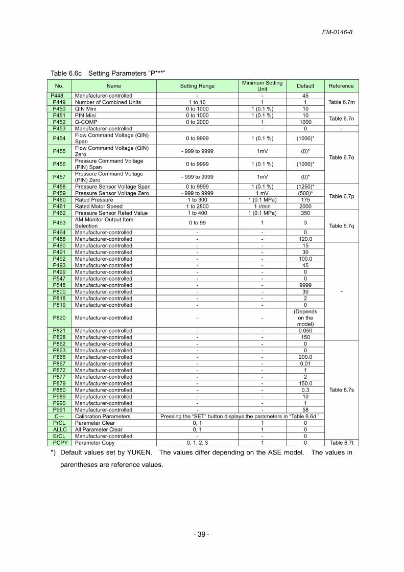
Table 6.6c Setting Parameters “P***”
No. Name Setting Range Minimum Setting Unit Default Reference
P448 Manufacturer-controlled - - 45 P449 Number of Combined Units 1 to 16 1 1 P450 QIN Mini 0 to 1000 1 (0.1 %) 10
Table 6.7m
P451 PIN Mini 0 to 1000 1 (0.1 %) 10 P452 Q-COMP 0 to 2000 1 1000 Table 6.7n
P453 Manufacturer-controlled - - 0 -
P454 Flow Command Voltage (QIN) Span 0 to 9999 1 (0.1 %) (1000)*
P455 Flow Command Voltage (QIN) Zero - 999 to 9999 1mV (0)*
P456 Pressure Command Voltage (PIN) Span 0 to 9999 1 (0.1 %) (1000)*
P457 Pressure Command Voltage (PIN) Zero - 999 to 9999 1mV (0)*
Table 6.7o
P458 Pressure Sensor Voltage Span 0 to 9999 1 (0.1 %) (1250)* P459 Pressure Sensor Voltage Zero - 999 to 9999 1 mV (500)* P460 Rated Pressure 1 to 300 1 (0.1 MPa) 175 P461 Rated Motor Speed 1 to 2800 1 r/min 2000
Table 6.7p
P462 Pressure Sensor Rated Value 1 to 400 1 (0.1 MPa) 350
P463 AM Monitor Output Item Selection 0 to 99 1 3
P464 Manufacturer-controlled - - 0 P488 Manufacturer-controlled - - 120.0
Table 6.7q
P490 Manufacturer-controlled - - 15 P491 Manufacturer-controlled - - 30 P492 Manufacturer-controlled - - 100.0 P493 Manufacturer-controlled - - 45 P499 Manufacturer-controlled - - 0 P547 Manufacturer-controlled - - 0 P548 Manufacturer-controlled - - 9999 P800 Manufacturer-controlled - - 30 P818 Manufacturer-controlled - - 2 P819 Manufacturer-controlled - - 0
P820 Manufacturer-controlled - - (Depends
on the model)
P821 Manufacturer-controlled - - 0.050 P828 Manufacturer-controlled - - 150
-
P862 Manufacturer-controlled - - 0 P863 Manufacturer-controlled - - 0 P866 Manufacturer-controlled - - 200.0 P867 Manufacturer-controlled - - 0.01 P872 Manufacturer-controlled - - 1 P877 Manufacturer-controlled - - 2 P879 Manufacturer-controlled - - 150.0 P880 Manufacturer-controlled - - 0.3 P989 Manufacturer-controlled - - 10 P990 Manufacturer-controlled - - 1 P991 Manufacturer-controlled - - 58 C--- Calibration Parameters Pressing the “SET” button displays the parameters in “Table 6.6d.”
PrCL Parameter Clear 0, 1 1 0 ALLC All Parameter Clear 0, 1 1 0 ErCL Manufacturer-controlled - - 0
Table 6.7s
PCPY Parameter Copy 0, 1, 2, 3 1 0 Table 6.7t
*) Default values set by YUKEN. The values differ depending on the ASE model. The values in
parentheses are reference values.

EM-0146-8
- - 40
Table 6.6d Setting Parameters “C_**” No. Name Setting Range Minimum
Setting Unit Default Reference
C 0 Manufacturer-controlled - - - C 1 AM Terminal Calibration - - - C 12 Manufacturer-controlled - - 0 C 13 Manufacturer-controlled - - 0.0 C 14 Manufacturer-controlled - - 900
C 15 Manufacturer-controlled - - 100.0 (0)*
Table 6.7v
*) By operating the “M Dial” with “0” displayed, the setting value (“100”) can be seen.
MEMO
-------------------------------------------------------------------------------------------------------------------------------
-------------------------------------------------------------------------------------------------------------------------------
-------------------------------------------------------------------------------------------------------------------------------
-------------------------------------------------------------------------------------------------------------------------------
-------------------------------------------------------------------------------------------------------------------------------
-------------------------------------------------------------------------------------------------------------------------------
-------------------------------------------------------------------------------------------------------------------------------
-------------------------------------------------------------------------------------------------------------------------------
-------------------------------------------------------------------------------------------------------------------------------
-------------------------------------------------------------------------------------------------------------------------------
-------------------------------------------------------------------------------------------------------------------------------
-------------------------------------------------------------------------------------------------------------------------------
-------------------------------------------------------------------------------------------------------------------------------
-------------------------------------------------------------------------------------------------------------------------------
-------------------------------------------------------------------------------------------------------------------------------
-------------------------------------------------------------------------------------------------------------------------------
-------------------------------------------------------------------------------------------------------------------------------
-------------------------------------------------------------------------------------------------------------------------------
-------------------------------------------------------------------------------------------------------------------------------
-------------------------------------------------------------------------------------------------------------------------------
-------------------------------------------------------------------------------------------------------------------------------
-------------------------------------------------------------------------------------------------------------------------------
-------------------------------------------------------------------------------------------------------------------------------
-------------------------------------------------------------------------------------------------------------------------------
-------------------------------------------------------------------------------------------------------------------------------
-------------------------------------------------------------------------------------------------------------------------------
-------------------------------------------------------------------------------------------------------------------------------

EM-0146-8
- - 41
6.7 Parameter functions Table 6.7a Parameter Functions No. Name Function/Use Default Setting Range
P 1 Upper Limit Frequency
Sets the upper limit of the motor output speed. Model Default ASE3 3000 ASE5 2500
ASE10 2200
See the table on the left.
0 to 3000 r/min
P 7 Acceleration Time Sets the motor acceleration time. Note) Do not set this value to less than 0.04.
0.04 0 to 15 s
P 8 Deceleration Time Sets the motor deceleration time. Note) Do not set this value to less than 0.04.
0.04 0 to 15 s
P 9 Manufacturer-controlled
* The setting value differs depending on the model. Model Default
ASE3-4AA 26.50 ASE3-AA 51.40 ASE5-4BZ 44.00 ASE5-BZ 84.00 ASE10 75.00
See the table on the left.
0 to 500 A
P 17 MRS Input Selection
Shuts off the output by a MRS signal. Setting Value Description
0 Normally open input 2 Normally closed input (Contact b input)
2 0, 2
MEMO
-------------------------------------------------------------------------------------------------------------------------------
-------------------------------------------------------------------------------------------------------------------------------
-------------------------------------------------------------------------------------------------------------------------------
-------------------------------------------------------------------------------------------------------------------------------
-------------------------------------------------------------------------------------------------------------------------------
-------------------------------------------------------------------------------------------------------------------------------
-------------------------------------------------------------------------------------------------------------------------------
-------------------------------------------------------------------------------------------------------------------------------
-------------------------------------------------------------------------------------------------------------------------------
-------------------------------------------------------------------------------------------------------------------------------
-------------------------------------------------------------------------------------------------------------------------------
-------------------------------------------------------------------------------------------------------------------------------
-------------------------------------------------------------------------------------------------------------------------------
-------------------------------------------------------------------------------------------------------------------------------
-------------------------------------------------------------------------------------------------------------------------------

EM-0146-8
- - 42
Table 6.7b Parameter Functions No. Name Function/Use Default Setting Range
P 52 Operation Panel Display Data Selection
Selects a monitoring item to be displayed on the operation panel and a monitoring item to be output to the terminal FM.* See “Table 6.7b-1” below.
0/ (100)
0, 5 to 14, 17, 20, 23, 25, 55, 81 to 86, 100
Table 6.7b-1 Operation Panel Display Data Selection Monitoring Item Setting Value Unit Description
Output Voltage 0/100 V Output voltage supplied to the motor side. Rotation Command 5 1 r/min Speed command. Motor Speed 6 1 r/min Motor speed. Motor Torque 7 0.1 % Torque value with the rated motor torque taken as 100 %. Converter Output Voltage 8 0.1 V DC bus voltage value.
Dynamic Brake Utilization 9 0.1 % Rate of dynamic brake utilization set by the setting parameters “P_30” and “P_70.”
Electronic Thermal Load Factor 10 0.1 % Accumulative value of motor thermal load with the electronic thermal
triggering level taken as 100 %.
Output Current Peak 11 0.1 A Retains the peak value for output current monitoring (memory is reset every time the unit starts up).
Converter Output Voltage Peak 12 0.1 V Retains the peak value of DC bus voltage (memory is reset every time
the unit starts up). Input Voltage 13 0.01 kW Voltage on the AMSE controller input side. Output Voltage 14 0.01 kW Voltage on the AMSE controller output side.
Load Meter 17 0.1 % Displays the torque current with the set value of “P_56” taken as 100 %.
Accumulative Power-on Time 20 1 h Accumulates the power-on time (0.001 = 1h: the value returns to 0 h
after reaching 65,535 h (max.)).
Actual Operating Time 23 1 h Accumulates the operating time (0.001 = 1 h: the value returns to 0 h after reaching 65,535 h (max.).
Accumulative Power Consumption 25 0.01 kW Displays the accumulative power consumption based on the
monitored output voltage.
Input Terminal Status - Displays the “ON/OFF” status of the control circuit input terminals on the operation panel. See “Fig. 6.7a” below for display details.
Output Terminal Status 55
- Displays the “ON/OFF” status of the control circuit output terminals on the operation panel. See “Fig. 6.7a” below for display details.
Pressure Input Command 81 0.01 V Pressure command voltage. Flow Input Command 82 0.01 V Flow command voltage AM Terminal Output 83 0.01 V Outputs an item selected by the setting parameter “P463.” Manufacturer-controlled - - An output value is invalid. Manufacturer-controlled - - An output value is invalid. Manufacturer-controlled - - An output value is invalid.
RL
RM
RH RT
AU
STOP MRS
RES
STF STR
JOG
CS
ABC1
ABC2
RUN SU
IPF
OL FUReserved
Reserved
Reserved Reserved
Reserved
Input Terminal
Output Terminal
Fig. 6.7a Status of Input/Output Terminals

EM-0146-8
- - 43
Table 6.7c Parameter Functions
No. Name Function/Use Default Setting Range
P 56 Manufacturer-controlled
* The setting value differs depending on the model. Model Default
ASE3-4AA 26.50 ASE3-AA 51.40 ASE5-4BZ 44.00 ASE5-BZ 84.00 ASE10 75.00
See the table on the left.
0 to 500 A
P 75 Reset/ PU Disconnection/ PU Stop Selection
Selects functions for reset input reception, operation panel connector disconnection (PU disconnection), and stop via the “STOP/RESET” button on the operation panel.
Setting Range
Reset Function Selection
Operation Panel
Disconnection
Stop via the STOP/RESET
Button 0 Always allowed.
1
Allowed when the protection
function is active.
Operation continues when the operation panel is
disconnected.2 Always allowed.
3
Allowed when the protection
function is active.
Operation stops when
the operation panel is
disconnected.
“STOP” is disabled.
14 Always allowed.
15
Allowed when the protection
function is active.
Operation continues when the operation panel is
disconnected.16 Always allowed.
17
Allowed when the protection
function is active.
Operation stops when
the operation panel is
disconnected.
“STOP” is always
enabled.
1 0 to 3, 14 to 17
P 77 Parameter Write Selection
Enables/disables write protection for parameters. This function can be used to prevent the parameters from being overwritten by mistake. Setting Range
Description
0 Writable only during stop. 1 Write-protected. 2 Writable regardless of the operation status.
2 0, 1, 2
P 80 Manufacturer-controlled
* The setting value differs depending on the model.
See the table on the left.
0.40 to 55.00
Model Default ASE3 11.00 ASE5 20.00
ASE10 35.00

EM-0146-8
- - 44
Table 6.7d Parameter Functions
No. Name Function/Use Default Setting Range
P161 Button Lock Operation Selection
Enables/disables button operation on the operation panel. Enabling the “button lock mode” and pressing the “MODE” button on the operation panel for 2 seconds disables button operation. When button operation is disabled, “HOLd” is displayed on the operation panel. To enable button operation, press the “MODE” button for 2 seconds to cancel the button lock mode.
Setting Range
Description
0 Puts the M dial into the motor speed setting mode.
1 Puts the M dial into the volume mode.
Button lock disabled
10 Puts the M dial into the motor speed setting mode
11 Puts the M dial into the volume mode.
Button lock enabled
10 0, 1, 10, 11
P244 Cooling Fan Operation Selection
Controls the operation of the cooling fan built in the inverter. Setting Range
Description
0 Starts the cooling fan when the power is turned “on.” The fan stays “on” while the power is “on.”
1
The cooling fan stays “on” during inverter operation. With the inverter stopped, the fan turns “on/off” according to the monitored inverter temperature.
1 0, 1
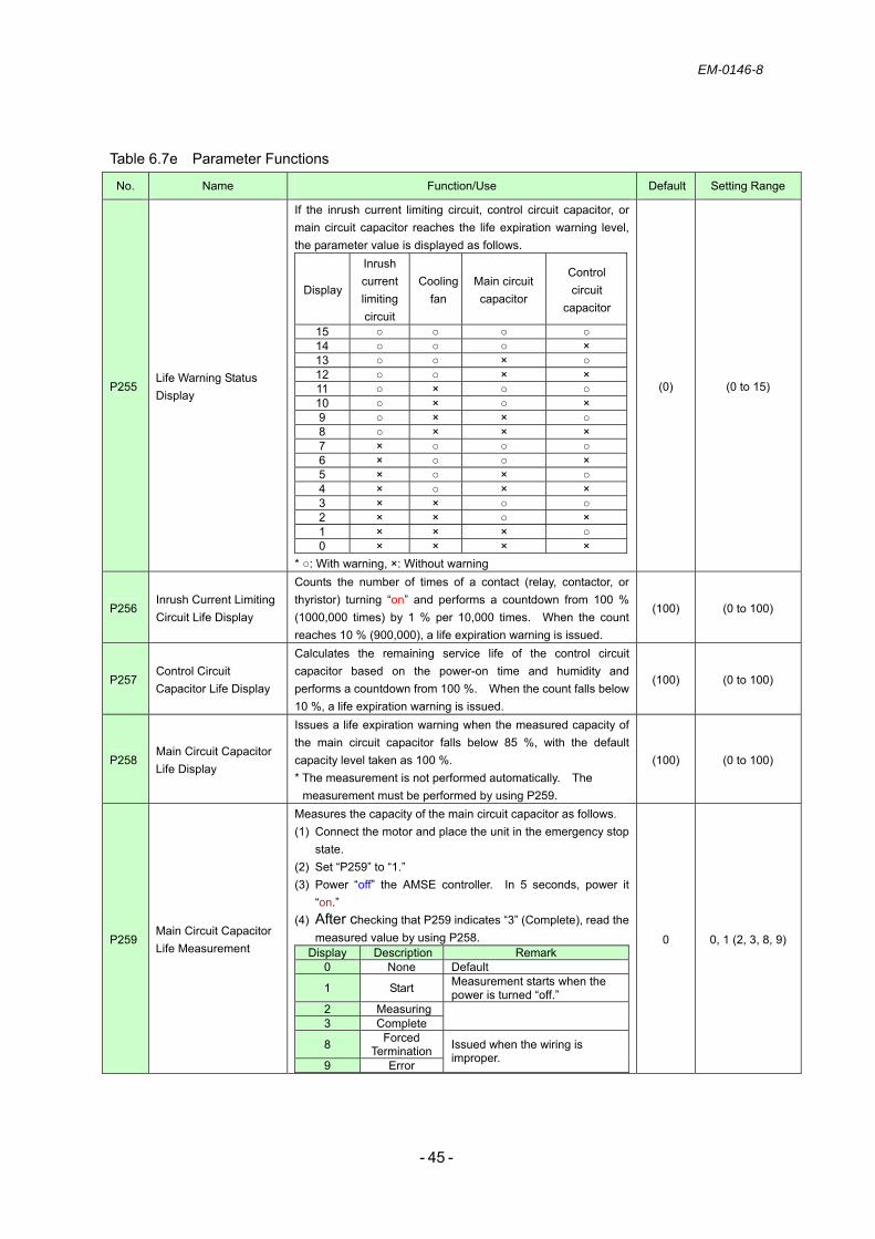
EM-0146-8
- - 45
Table 6.7e Parameter Functions
No. Name Function/Use Default Setting Range
P255 Life Warning Status Display
If the inrush current limiting circuit, control circuit capacitor, or main circuit capacitor reaches the life expiration warning level, the parameter value is displayed as follows.
Display
Inrush current limiting circuit
Cooling fan
Main circuit capacitor
Control circuit
capacitor
15 14 × 13 × 12 × × 11 × 10 × × 9 × × 8 × × × 7 × 6 × × 5 × × 4 × × × 3 × × 2 × × × 1 × × × 0 × × × ×
* : With warning, ×: Without warning
(0) (0 to 15)
P256 Inrush Current Limiting Circuit Life Display
Counts the number of times of a contact (relay, contactor, or thyristor) turning “on” and performs a countdown from 100 % (1000,000 times) by 1 % per 10,000 times. When the count reaches 10 % (900,000), a life expiration warning is issued.
(100) (0 to 100)
P257 Control Circuit Capacitor Life Display
Calculates the remaining service life of the control circuit capacitor based on the power-on time and humidity and performs a countdown from 100 %. When the count falls below 10 %, a life expiration warning is issued.
(100) (0 to 100)
P258 Main Circuit Capacitor Life Display
Issues a life expiration warning when the measured capacity of the main circuit capacitor falls below 85 %, with the default capacity level taken as 100 %. * The measurement is not performed automatically. The
measurement must be performed by using P259.
(100) (0 to 100)
P259 Main Circuit Capacitor Life Measurement
Measures the capacity of the main circuit capacitor as follows. (1) Connect the motor and place the unit in the emergency stop
state. (2) Set “P259” to “1.” (3) Power “off” the AMSE controller. In 5 seconds, power it
“on.” (4) After checking that P259 indicates “3” (Complete), read the
measured value by using P258. Display Description Remark
0 None Default
1 Start Measurement starts when the power is turned “off.”
2 Measuring3 Complete
8 Forced Termination
9 Error
Issued when the wiring is improper.
0 0, 1 (2, 3, 8, 9)

EM-0146-8
- - 46
Table 6.7h Parameter Functions
No. Name Function/Use Default Setting Range
P402
P409
P416
P423
No. 0 Rise Time Gain No. 1 Rise Time Gain No. 2 Rise Time Gain
No. 3 Rise Time Gain
Sets the pressure control gain at the pressure rise time. Increasing the setting value improves the response, but an excessively high value may result in vibrations.
1500 0 to 9999
P403
P410
P417
P424
No. 0 Fall Time Gain No. 1 Fall Time Gain No. 2 Fall Time Gain No. 3 Fall Time Gain
Sets the pressure control gain at the pressure fall time. Increasing the setting value improves the response, but an excessively high value may result in vibrations.
1500 0 to 9999
Pre
ssur
e
Time
The value increases.
Time
Pre
ssur
e
The value increases.

EM-0146-8
- - 47
Table 6.7i Parameter Functions
No. Name Function/Use Default Setting Range
P404
P411
P418
P425
No. 0 Lag Compensation No. 1 Lag Compensation No. 2 Lag Compensation No. 3 Lag Compensation
Sets the pressure control lag time constant. Lag compensation is used when the control gain cannot be increased, and the operation is not stabilized. It can prevent oscillations in a frequency band of several Hz. Excessively increasing the value deteriorates the response and overshoot characteristics; it is recommended to adjust it in combination with lead compensation.
70 1 to 2000
P405
P412
P419
P426
No. 0 Lead Compensation No. 1 Lead Compensation No. 2 Lead Compensation No. 3 Lead Compensation
Sets the pressure control lead time constant. Lead compensation is used to improve the damping characteristics by preventing overshooting. Excessively increasing the value may result in oscillations in a high frequency band.
60 1 to 2000
Pre
ssur
e
Time
The value increases.
Pre
ssur
e
Time
The value increases.

EM-0146-8
- - 48
Table 6.7j Parameter Functions
No. Name Function/Use Default Setting Range
P406
P413
P420
P427
No. 0 Rise Time Pressure Command Filter No. 1 Rise Time Pressure Command Filter No. 2 Rise Time Pressure Command Filter No. 3 Rise Time Pressure Command Filter
Sets the first-order lag filter for pressure command input. It can be set at the pressure rise time. It prevents overshooting in the case of stepped changes in pressure command voltage.
300 1 to 2000
P407
P414
P421
P428
No. 0 Fall Time Pressure Command Filter No. 1 Fall Time Pressure Command Filter No. 2 Fall Time Pressure Command Filter No. 3 Fall Time Pressure Command Filter
Sets the first-order lag filter for pressure command input. It can be set at the pressure fall time. It prevents undershooting in the case of stepped changes in pressure command voltage.
300 1 to 2000
Pre
ssur
e
Time
The value increases.
Pre
ssur
e
Time
The value increases.
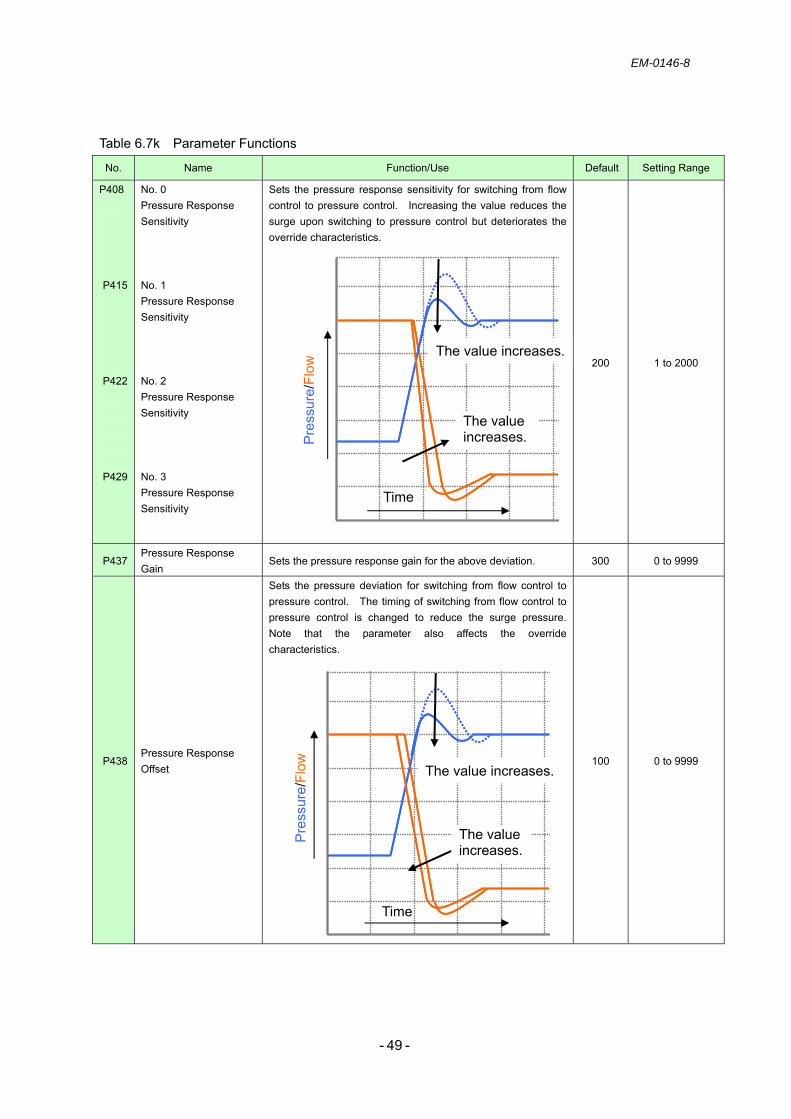
EM-0146-8
- - 49
Table 6.7k Parameter Functions
No. Name Function/Use Default Setting Range
P408
P415
P422
P429
No. 0 Pressure Response Sensitivity No. 1 Pressure Response Sensitivity No. 2 Pressure Response Sensitivity No. 3 Pressure Response Sensitivity
Sets the pressure response sensitivity for switching from flow control to pressure control. Increasing the value reduces the surge upon switching to pressure control but deteriorates the override characteristics.
200 1 to 2000
P437 Pressure Response Gain
Sets the pressure response gain for the above deviation. 300 0 to 9999
P438 Pressure Response Offset
Sets the pressure deviation for switching from flow control to pressure control. The timing of switching from flow control to pressure control is changed to reduce the surge pressure. Note that the parameter also affects the override characteristics.
100 0 to 9999
Pre
ssur
e/Fl
ow
Time
The value increases.
The value increases.
Pre
ssur
e/Fl
ow
The value increases.
The value increases.
Time

EM-0146-8
- - 50
Table 6.7l Parameter Functions
No. Name Function/Use Default Setting Range
P439 Pressure Proportional Gain
This proportional gain is independent of control compensation, unlike the rise or fall time gain. It improves the response and minimizes disturbance. Since the response is not regulated by control compensation, an excessively high value may result in oscillations.
0 0 to 9999
P440 Pressure Feedforward Gain
0 0 to 9999
P441 Pressure Feedforward Filter
1 1 to 2000
P442 Pressure Feedforward Function Selection
Performs the feedforward control of changes in pressure command voltage (derivative) to improve the pressure wave response. - Feedforward Gain: Sets the sensitivity added to pressure control in relation to the change described above. - Feedforward Filter: Filters the return of feedforward signals to keep the function effective against sudden changes. - Feedforward Function Selection: Selects the method of adding feedforward signals.
0: Adding to pressure control at both the pressure rise and fall times.
1: Adding to pressure control at the pressure rise time only. 2: Adding to flow control at both the pressure rise and fall
times. 3: Adding to flow control at the pressure rise time only.
0 0, 1, 2, 3
Pressure Command [V]
Gain
FilterFeedforward Signal

EM-0146-8
- - 51
Table 6.7m Parameter Functions
No. Name Function/Use Default Setting Range
P443 Q-damping Gain 0 - 999 to 9999
P444 Q-damping filter
Detects the motor speed during pressure control and adds its derivative to pressure control. This function is effective when the pressure trackability is not good due to a large compression volume on the load side.
- Q-damping Gain: Sets the sensitivity added to pressure control in relation to the change described above.
- Q-damping Filter: Filters the return of Q-damping control signals to keep the function effective against sudden changes.
1 1 to 2000
P449 Number of Combined Units
1 1 to 16
P450 QIN Mini
Inputs the required number of units for combination use. Sets the lower limit of the motor speed in relation to flow (motor speed) command voltage. It prevents reverse rotation of the pump due to command voltage variations caused by noise or due to improper operation/input. e.g.) If the parameter is set to 10 (1.0 %) with a rated motor
speed of 2000 rpm, the minimum motor speed is 20 rpm.
10 0 to 1000 × 0.1 %
Motor Speed[r/min]
GainFilter
Q-damping Signal
0.0 20
0.05
Motor Speed [rpm]
5.0 [V]100.0 [%][1.0]
Setting Value of Command
Voltage
2000

EM-0146-8
- - 52
Table 6.7n Parameter Functions
No. Name Function/Use Default Setting Range
P451 PIN Mini
Sets the lower limit of the pressure in relation to pressure command voltage. It prevents reverse rotation of the pump due to command voltage variations caused by noise or due to improper operation/input. e.g.) If the parameter is set to 10 (1.0 %) with a rated pressure
of 17.5 MPa, the minimum pressure is 0.175 MPa (calculated value).
10 0 to 1000 × 0.1 %
P452 Q-COMP
Compensates for leakage inside the pump in relation to load pressure. As load pressure increases, the leakage level in the pump rises, resulting in lower flow. To prevent this problem, a compensation value proportional to load pressure is added to the flow command.
1000 0 to 2000
MEMO
-------------------------------------------------------------------------------------------------------------------------------
-------------------------------------------------------------------------------------------------------------------------------
-------------------------------------------------------------------------------------------------------------------------------
-------------------------------------------------------------------------------------------------------------------------------
-------------------------------------------------------------------------------------------------------------------------------
-------------------------------------------------------------------------------------------------------------------------------
-------------------------------------------------------------------------------------------------------------------------------
-------------------------------------------------------------------------------------------------------------------------------
-------------------------------------------------------------------------------------------------------------------------------
-------------------------------------------------------------------------------------------------------------------------------
-------------------------------------------------------------------------------------------------------------------------------
0.0
0.175
0.05
Pressure[MPa]
5.0 [V]100.0 [%][1.0]
Setting Value of Command
Voltage
17.5
0.0
Motor Speed[rpm]
17.5Pressure [MPa]
The value increases.

EM-0146-8
- - 53
Table 6.7o Parameter Functions
No. Name Function/Use Default Setting Range
P454 Flow Command Voltage Span
1000 0 to 9999 × 0.1 %
P455 Flow Command Voltage Zero
Adjusts the span of flow (motor speed) command voltage. This parameter provides the variable control of pump motor speed in relation to command voltage. At the default value, or 1000 (100.0 %), the rated motor speed is achieved with the input of a command voltage of 5 V. The zero point of command voltage is adjusted by “P455.” e.g.) When the command at the output side is zero and the
terminal block voltage (between 4 and 5) is 50 mv, input +50.
0 - 999 to 9999 ×
0.1 %
P456 Pressure Command Voltage Span
1000 0 to 9999 × 0.1 %
P457 Pressure Command Voltage Zero
Adjusts the span of pressure command voltage. This parameter provides the variable control of pressure in relation to command voltage. At the default value, or 1000 (100.0 %), the rated pressure is achieved with the input of a command voltage of 5 V. The zero point of command voltage is adjusted by “P457.” e.g.) When the command at the output side is zero and the
terminal block voltage (between 2 and 5) is 50 mv, input +50.
0 - 999 to 9999 ×
0.1 %
MEMO
-------------------------------------------------------------------------------------------------------------------------------
-------------------------------------------------------------------------------------------------------------------------------
-------------------------------------------------------------------------------------------------------------------------------
-------------------------------------------------------------------------------------------------------------------------------
-------------------------------------------------------------------------------------------------------------------------------
0.0
2000
Motor Speed[rpm]
5.0 [V]QIN Command Voltage
P454
P455
0.0
17.5
Pressure[MPa]
5.0 [V]PIN Command Voltage
P456
P457

EM-0146-8
- - 54
Table 6.7p Parameter Functions
No. Name Function/Use Default Setting Range
P458 Pressure Sensor Span 1250 0 to 9999 × 0.1 %
P459 Pressure Sensor Zero
Adjusts the zero point/span of pressure sensor input voltage. According to the output voltage specification of the pressure sensor, set the parameters as follows.
Pressure Sensor Zero
Pressure Sensor Span
Pressure Sensor Output Voltage
P459 P458 0.5 to 4.5 V 500 1250
0 to 5 V 0 1000 1 to 5 V 1000 1250
* By default, the values for 0.5 to 4.5 V are set.
500 - 999 to 9999
Mv
P460 Rated Pressure
Sets the pressure at a pressure command voltage of DC + 5 V. This parameter is used to change the rated pressure without changing the pressure command voltage. When pressure monitoring (SMP) is selected for AM monitoring output, the set pressure is output at DC + 5 V.
175 1 to 300
× 0.1 MPa
P461 Rated Motor Speed
Sets the motor speed at a flow command voltage of DC + 5 V. This parameter is used to change the rated motor speed without changing the flow command voltage. When motor speed monitoring (SMN) is selected for AM monitoring output, the set motor speed is output at DC + 5 V.
2000 1 to 3000
r/min
0.0
17.5
Pressure[MPa]
5.0 [V] PIN Command
0.0
2000
Motor Speed[r/min]
5.0 [V] QIN Command
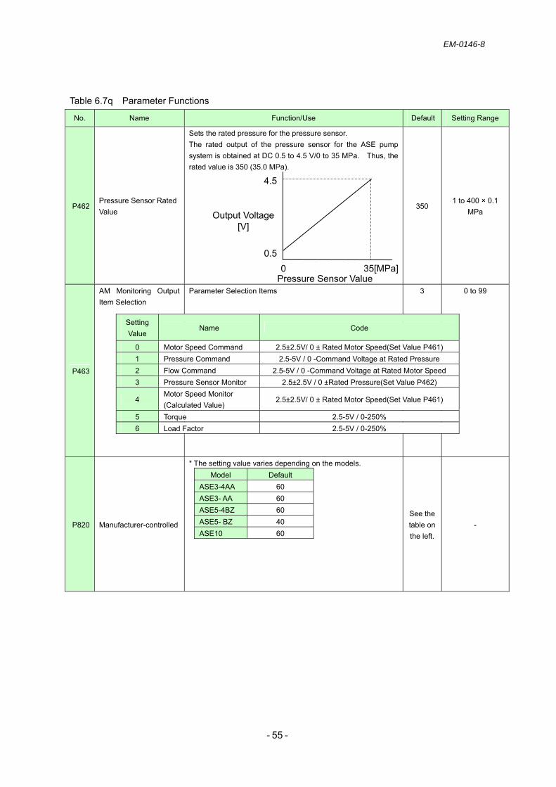
EM-0146-8
- - 55
Table 6.7q Parameter Functions
No. Name Function/Use Default Setting Range
P462 Pressure Sensor Rated Value
Sets the rated pressure for the pressure sensor. The rated output of the pressure sensor for the ASE pump system is obtained at DC 0.5 to 4.5 V/0 to 35 MPa. Thus, the rated value is 350 (35.0 MPa).
350 1 to 400 × 0.1
MPa
P463
AM Monitoring Output Item Selection
Parameter Selection Items
3 0 to 99
P820 Manufacturer-controlled
* The setting value varies depending on the models. Model Default
ASE3-4AA 60 ASE3- AA 60 ASE5-4BZ 60 ASE5- BZ 40 ASE10 60
See the table on the left.
-
0
4.5
Output Voltage[V]
35[MPa] Pressure Sensor Value
0.5
Setting Value
Name Code
0 Motor Speed Command 2.5±2.5V/ 0 ± Rated Motor Speed(Set Value P461) 1 Pressure Command 2.5-5V / 0 -Command Voltage at Rated Pressure 2 Flow Command 2.5-5V / 0 -Command Voltage at Rated Motor Speed 3 Pressure Sensor Monitor 2.5±2.5V / 0 ±Rated Pressure(Set Value P462)
4 Motor Speed Monitor (Calculated Value)
2.5±2.5V/ 0 ± Rated Motor Speed(Set Value P461)
5 Torque 2.5-5V / 0-250% 6 Load Factor 2.5-5V / 0-250%
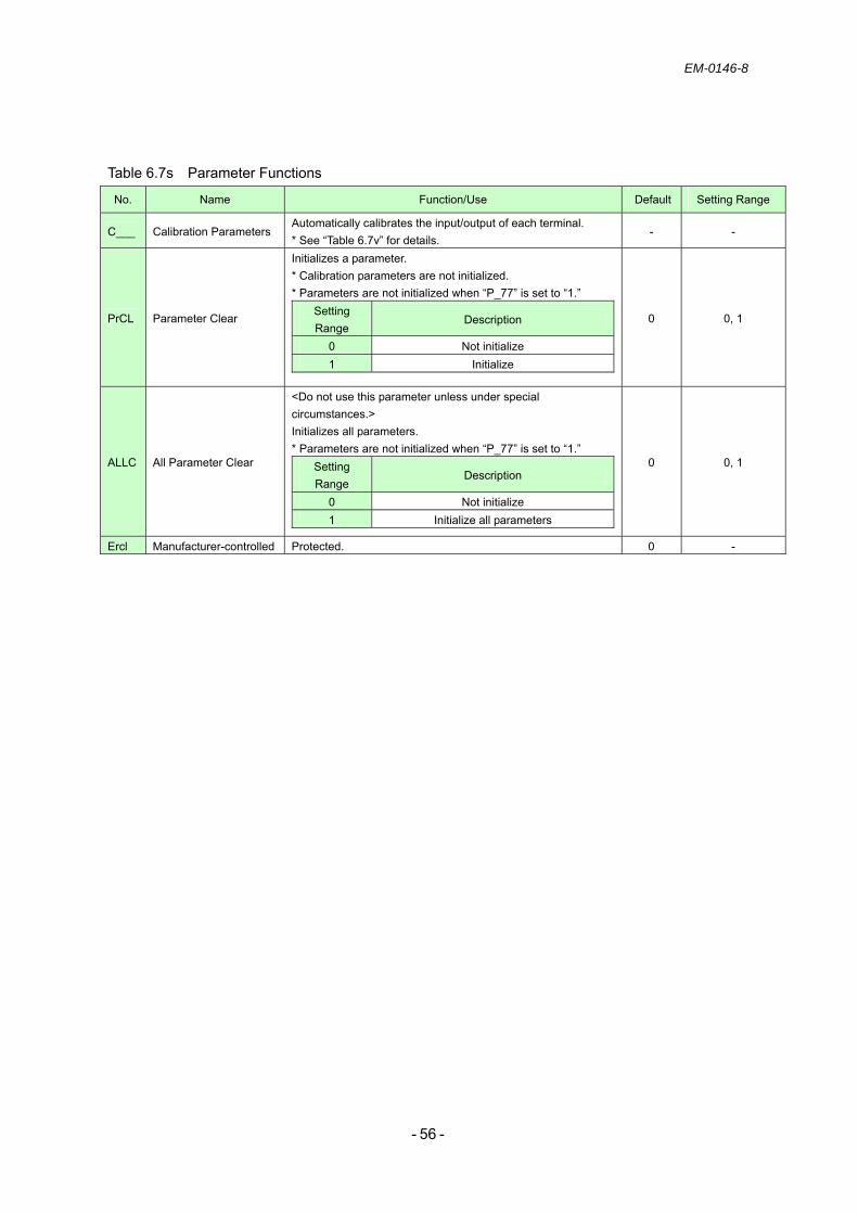
EM-0146-8
- - 56
Table 6.7s Parameter Functions
No. Name Function/Use Default Setting Range
C___ Calibration Parameters Automatically calibrates the input/output of each terminal. * See “Table 6.7v” for details.
- -
PrCL Parameter Clear
Initializes a parameter. * Calibration parameters are not initialized. * Parameters are not initialized when “P_77” is set to “1.”
Setting Range
Description
0 Not initialize 1 Initialize
0 0, 1
ALLC All Parameter Clear
<Do not use this parameter unless under special circumstances.> Initializes all parameters. * Parameters are not initialized when “P_77” is set to “1.”
Setting Range
Description
0 Not initialize 1 Initialize all parameters
0 0, 1
Ercl Manufacturer-controlled Protected. 0 -
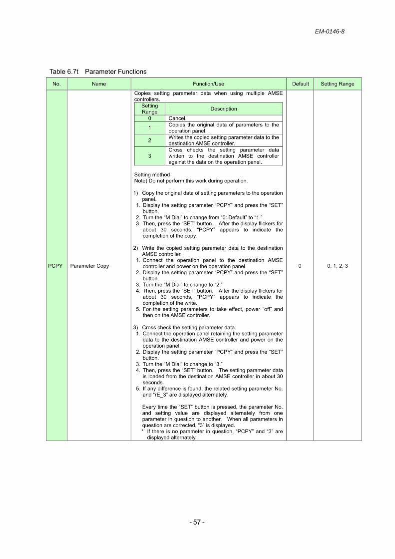
EM-0146-8
- - 57
Table 6.7t Parameter Functions
No. Name Function/Use Default Setting Range
PCPY Parameter Copy
Copies setting parameter data when using multiple AMSE controllers.
Setting Range Description
0 Cancel.
1 Copies the original data of parameters to the operation panel.
2 Writes the copied setting parameter data to the destination AMSE controller.
3 Cross checks the setting parameter data written to the destination AMSE controller against the data on the operation panel.
Setting method Note) Do not perform this work during operation. 1) Copy the original data of setting parameters to the operation
panel. 1. Display the setting parameter “PCPY” and press the “SET”
button. 2. Turn the “M Dial” to change from “0: Default” to “1.” 3. Then, press the “SET” button. After the display flickers for
about 30 seconds, “PCPY” appears to indicate the completion of the copy.
2) Write the copied setting parameter data to the destination
AMSE controller. 1. Connect the operation panel to the destination AMSE
controller and power on the operation panel. 2. Display the setting parameter “PCPY” and press the “SET”
button. 3. Turn the “M Dial” to change to “2.” 4. Then, press the “SET” button. After the display flickers for
about 30 seconds, “PCPY” appears to indicate the completion of the write.
5. For the setting parameters to take effect, power “off” and then on the AMSE controller.
3) Cross check the setting parameter data. 1. Connect the operation panel retaining the setting parameter
data to the destination AMSE controller and power on the operation panel.
2. Display the setting parameter “PCPY” and press the “SET” button.
3. Turn the “M Dial” to change to “3.” 4. Then, press the “SET” button. The setting parameter data
is loaded from the destination AMSE controller in about 30 seconds.
5. If any difference is found, the related setting parameter No. and “rE_3” are displayed alternately.
Every time the “SET” button is pressed, the parameter No. and setting value are displayed alternately from one parameter in question to another. When all parameters in question are corrected, “3” is displayed. * If there is no parameter in question, “PCPY” and “3” are
displayed alternately.
0 0, 1, 2, 3

EM-0146-8
- - 58
Table 6.7v Parameter Functions
No. Name Function/Use Default Setting Range
C__1 AM Terminal Calibration Calibrates the scale of the meter connected to the control circuit terminal “AM.”
- -
MEMO
-------------------------------------------------------------------------------------------------------------------------------
-------------------------------------------------------------------------------------------------------------------------------
-------------------------------------------------------------------------------------------------------------------------------
-------------------------------------------------------------------------------------------------------------------------------
-------------------------------------------------------------------------------------------------------------------------------
-------------------------------------------------------------------------------------------------------------------------------
-------------------------------------------------------------------------------------------------------------------------------
-------------------------------------------------------------------------------------------------------------------------------
-------------------------------------------------------------------------------------------------------------------------------
-------------------------------------------------------------------------------------------------------------------------------
-------------------------------------------------------------------------------------------------------------------------------
-------------------------------------------------------------------------------------------------------------------------------
-------------------------------------------------------------------------------------------------------------------------------
-------------------------------------------------------------------------------------------------------------------------------
-------------------------------------------------------------------------------------------------------------------------------
-------------------------------------------------------------------------------------------------------------------------------
-------------------------------------------------------------------------------------------------------------------------------
-------------------------------------------------------------------------------------------------------------------------------
-------------------------------------------------------------------------------------------------------------------------------
-------------------------------------------------------------------------------------------------------------------------------
-------------------------------------------------------------------------------------------------------------------------------
-------------------------------------------------------------------------------------------------------------------------------
-------------------------------------------------------------------------------------------------------------------------------
-------------------------------------------------------------------------------------------------------------------------------
-------------------------------------------------------------------------------------------------------------------------------
-------------------------------------------------------------------------------------------------------------------------------
-------------------------------------------------------------------------------------------------------------------------------
-------------------------------------------------------------------------------------------------------------------------------
-------------------------------------------------------------------------------------------------------------------------------
-------------------------------------------------------------------------------------------------------------------------------
-------------------------------------------------------------------------------------------------------------------------------

EM-0146-8
- - 59
7. Troubleshooting 7.1 Error indication
The ASE pump unit can issue “alarms” that are generated with the detection of system errors and stop system operation, “warnings” that are generated with the detection of system errors but allow continued system operation, and “error messages” generated by improper operation. The monitor of the operation panel indicates a code for each error. The user can identify the error cause by referring to this manual.
7.1.1 Alarms
An alarm is displayed when significant failure occurs to the ASE pump unit. Take appropriate measures in the event of an alarm. Any alarm shuts off the output and stops system operation, while the AMSE controller outputs an alarm signal. The operation panel displays the code for the alarm (see Table 7.1a below). Reset the alarm after removing the error cause and then restart system operation.
Note) Alarms are output via relay contacts. For details, see “Table 2.7c: Alarm Output.” Note) Alarm codes are output via the open collector. For details, see “Table 2.7d: Sequence
Output.” Table 7.1a Alarm Codes
Note 1) After removing the error cause, wait about 30 minutes until the unit cools down.
Alarm Code Alarm FU SU IPF Name Reference Alarm Reset
E. PE Parameter Memory Device Error
E. 6 E. 7 E.CPU
CPU Error
E.IOH Inrush Current Limiting Circuit Error
E.AIE Analog Input Error E.OPΓ Option Error E.SEr Communication Error E. 13 Internal Circuit Error
E.P24 DC 24 Power Output Short Circuit
Table 7.2a
E.CΓE Operation Panel Power Short Circuit
E.USb USB Communication Error
E.OP3 Hydraulic Control Board Error
E. 3
OFF OFF OFF
Hydraulic Control Board Communication Error
E.Ov3 Regeneration Overvoltage
E._bE OFF OFF ON Brake Transistor Error Detection
E.UuΓ Undervoltage E.IPF OFF ON OFF Instantaneous Power FailureE.ΓHΓ AMSE Controller Overload E.ΓHП Motor Overload
Table 7.2b
E.FIn Fin Overheat E.OLΓ
OFF ON ON
Stall Prevention E.OC3 Overcurrent
E. GF ON OFF OFF Ground Fault Overcurrent on the Output Side
E.ILF Input Phase Failure E. LF Output Phase Failure E.PUE
ON ON ON PU Disconnection
Table 7.2c
1) To reset an alarm, press
on the operation panel.
2)
Turn “off” and the on the power. 3)
Turn “on” RES (Reset Signal) for at least 0.1 second. Note) For details, see “Table
2.7a: Sequence Input.”

EM-0146-8
- - 60
7.1.2 Warnings When the probability of the failure of the ASE pump unit is determined, warnings are displayed before alarm output. Take appropriate measures in the event of a warning. While the system continues operation, the AMSE controller outputs a warning signal, and the operation panel displays the code for the warning. When any warning is output, take measures to prevent the occurrence of serious failure.
Table 7.1b Warnings
7.1.3 Error messages In the event of setting failure due to improper operation, an error code is displayed on the operation panel. Set the relevant parameter properly by referring to this manual.
Table 7.1c Error Messages
7.1.4 Status display During operation, the operation status code is displayed on the operation panel.
Table 7.1d Status Display
Error Message Name Reference
HOLD Operation Panel Lock Er 1 Parameter Write Error - 1 Er 2 Parameter Write Error - 2 Er 3 Parameter Write Error - 3 Er 4 Parameter Write Error - 4 rE 1 Copy Operation Error - 1 rE 2 Copy Operation Error - 2 rE 3 Copy Operation Error - 3 rE 4 Copy Operation Error - 4 Err Error
Table 7.2e
Warning Name Reference
OL Stall Prevention (Overcurrent) Rb Dynamic Brake Pre-alarm ΓH Electronic Thermal Pre-alarm PS PU Stop CP Parameter Copy Fn Fan Fault oP Hydraulic Control Board Warning
Table 7.2d
Note) Contact us when other warning codes are displayed.
Status Name Reference
EПG Emergency Stop Table 7.2f

EM-0146-8
- - 61
7.2 Measures against alarms (error indication)
An alarm can be reset by powering off and then on the unit, pressing the “STOP/RESET” button on the operation panel, or turning on RES (Reset).
Table 7.2a Measures Against Alarms Alarm Name Description Cause Remedy
E. PE Parameter Memory Device Error
EEPROM failure (control board).
Excessive parameter write operations. - Replace the AMSE controller
E. 6 E. 7 E.CPU
CPU Error Communication error of the built-in CPU. Noise.
- Take measures against devices producing excessive noise near the AMSE controller.
E.IOH Inrush Current Limiting Circuit Error
The resistor of the inrush current limiting circuit has overheated.
Repeated power-on/off cycles.
Replace the circuit with the one that does not perform frequent power-on/off cycles.
E.AIE Analog Input Error
Input of 30 mA or more or voltage input after changing the control circuit terminals “2” and “4” to the settings for current command specifications.
Change of the setting of the voltage/current switch.
Correct the setting of the voltage/current switch.
Failure of the hydraulic control board connector.
Check the connection of the hydraulic control board.
E.OPΓ Option Error Communication circuit error of a communication option. Communication error
due to a parameter setting change.
Initialize the setting parameter.
E.SEr Communication Error
RS-485 communication error
The number of communication errors has exceeded the allowable threshold set by the setting parameter “335: RS-485 Communication Retry Count” (excluding “9999”). The communication downtime is longer than the threshold set by the setting parameter “336: RS-485 Communication Check Time Interval.”
- Set the parameter with sufficient margin.
- Modify the wiring to ensure the availability of RS-485 communication.
E. 13 Internal Circuit Error Internal circuit error. Failure. Contact the place of purchase.
E.P24 DC 24 Power Output Short Circuit
Short circuit of DC 24 V power supplied from the control circuit terminal “PC.”
Short circuit of the PC terminal.
Disconnect the wire from the PC terminal to check whether the error can be removed. Then, check whether the wire connected to the PC terminal is short-circuited.
♦ When an alarm occurs, remove its cause and ensure safety. Then, reset the alarm and restart system operation.
♦ When an alarm occurs, immediately turn “off” STF (Serve-on) and shut off the power supply.
♦ If any of the following alarms occurs, do not restart operation by resetting the alarm. Doing so may cause failure of the servo amplifier or motor. In such cases, remove the alarm cause and wait 30 minutes or more until the unit cools down. Then, restart operation: E.IOH, E.ΓHΓ, or E.ΓHП.
CAUTION

EM-0146-8
- - 62
Table 7.2b Measures Against Alarms Alarm Name Description Cause Remedy
E.CΓE
Operation Panel Power Short Circuit RS-485 Terminal Power Short Circuit
Short circuit of the operation panel power (PU connector). Short circuit of the RS-485 terminal power.
Short circuit of the power cable of each power supply.
Check the short-circuited part. Replace the operation panel.
E.USb USB Communication Error
Interruption of USB communication. Contact failure. Check the cable.
E.OP3 Hydraulic Control Board Error
Pressure sensor output error. EEPROM error.
Disconnection of the pressure sensor. EEPROM read error.
Check the wiring. Replace the wiring. Replace the pressure sensor.
E. 3
Hydraulic Control Board Communication Error
Interruption of communication between the hydraulic control board and the driver.
Contact failure of the connector. Board failure.
Replace the AMSE controller.
E.Ov3 Regenerative overvoltage
Regeneration during deceleration/stop. Overvoltage shutdown.
Rapid deceleration.
Increase the deceleration time. Reduce the braking frequency. Use a brake unit/power regenerative converter, if required.
E. bE Brake Transistor Error Detection
Damage to the brake transistor or brake circuit failure.
A large volume of released pressure. High braking frequency (the cycle time must be set with sufficient margin).
The replacement of the AMSE controller is required.
E.UuΓ Undervoltage
The primary power voltage applied to “R/L1,” “S/L2,” and “T/L3” of the main circuit terminal block is 300 V or less. The short bar between “P/+” and “P1” of the main circuit terminal block or DC reactor is connected.
Low power voltage. Any factor that reduces the main power voltage and causes the error (startup of a large-size motor, etc.).
Check the power facilities. If a DC reactor is in use, check the wiring.
E.IPF Instantaneous Power Failure
Power failure lasting more than 15 ms. *1: This error is not output
in the case of a power failure of more than 100 ms.
*2: The operation continues in the event of an instantaneous power failure of 15 ms or less.
Interruption of power supply for more than 15 ms but less than 100 ms.
Remove the cause of instantaneous power failure. Prepare a backup power supply for instantaneous power failure.
E.ΓHΓ
AMSE Controller Overload Shutdown
When the rated output current is exceeded and if overcurrent shutdown does not occur, the electronic thermal with inverse time characteristics is activated for output transistor protection.
The motor’s rated load factor has been exceeded.
Reduce the load. - Reduce the pressure setting. - Reduce the cycle load by operating
the system at intervals.
E.ΓHП Motor Overload Shutdown
The electronic thermal in the AMSE controller has detected a motor overheat caused by overload or reduced cooling capability during constant speed operation.
High overload factor of the motor. The set value of the setting parameter “71: Applicable Motor” is improper.
Modify the motor environment (ambient temperature). Check that the motor fan works normally.

EM-0146-8
- - 63
Table 7.2c Measures Against Alarms
Alarm Name Description Cause Remedy
E.FIn Fin Overheat The cooling fin of the AMSE controller has overheated.
1) Ambient temperature around the AMSE controller is high.
2) The cooling fin has been clogged.
3) The cooling fan has stopped.
1) Check that the ambient temperature is as specified.
2) Clean the cooling fin. 3) Replace the cooling fan.
E.OLΓ Stall Prevention
The operation has been stopped by the torque limiting function.
Overload. Reduce the load.
Operation at zero rotation.
Avoid operating at near-zero rotation.
Rapid deceleration. Increase the deceleration time. E.OC3 Overcurrent The current level has exceeded the specified current value.
Output short circuit. Check the wiring.
E._GF Ground Fault Overcurrent on the Output Side
A ground fault has occurred on the output side of the AMSE controller.
Restore the section where the ground fault has occurred.
E.ILF Input Open-phase
One of the three input power phases has opened.
Disconnection of the 3-phase power cable.
Check the wiring.
E.PUE PU Disconnection
Interruption of communication between the operation panel and the PU terminals.
Disconnection of the operation panel. Setting of the setting parameter “P_75: Reset” at “2,” “3,” “16,” or “17.”
Reset “P_75” to “0,” “1,” “14,” or “15” so that the operation continues when the operation panel is disconnected.

EM-0146-8
- - 64
Table 7.2d Measures Against Warnings
Alarm Name Description Cause Remedy
OL Stall Prevention (Overcurrent)
The threshold set by the setting parameter “P_22: Stall Prevention Operation Level” has been exceeded.
The load is too high.
Reduce the load. Increase the settings of “P__7: Acceleration Time” and “P__8: Deceleration Time.” Check that the setting parameter “P_13” has been set to “0.”
rb Dynamic Brake Pre-alarm
The dynamic brake utilization has exceeded 85 % of the set value.
The frequency of the dynamic brake utilization is high.
Increase the setting of “P__8: Deceleration Time” (extend the deceleration time).
ΓH Electronic Thermal Pre-alarm
The value has exceeded 85 % of the set value of “P__9: Electronic Thermal.”
The load is too high. Too frequent rapid acceleration/ deceleration.
Reduce the load and operation frequency.
PS PU Stop The “STOP” button has been enabled by the setting parameter “P_75: Reset.”
The operation has been stopped by the “STOP” button.
After turning off the servo, press the “STOP/RESET” button for recovery. Turn “on” the terminal “RES” for recovery.
CP Parameter Copy
Parameter data has been copied between different AMSE controllers.
Initialize the setting parameter “P989: Parameter Copy Warning Reset.”
Fn Fan Fault
The fan in the AMSE controller has failed and stopped, or its rotational speed has decreased.
Fan failure. Contact the place of purchase.
oP Hydraulic Control Board Warning
Setting error.
Mismatch between the combination use setting area and the combination use setting parameter.
See “8: Combination use” to check the setting of combination/single use.

EM-0146-8
- - 65
Table 7.2e Measures Against Error Messages
Alarm Name Description/Cause Remedy
HOLD Operation Panel Lock
The operation lock mode is active. Press the “MODE” button on the operation panel for 2 seconds or more (to disable the operation lock).
The setting parameter “P_77: Parameter Write Selection” has been set to “1.”
Change the setting of “P_77: Parameter Write Selection.”
Er 1 Write Protection Error
The operation panel has not been mounted to the AMSE controller properly.
Check the connection between the operation panel and the PU connector.
Er 2 Write During Operation
A write was performed during operation with STF (STR) - SD set to “on.”
Stop the operation. Change the setting of “P_77: Parameter Write Selection.”
Er 3 Er 4
Modify the settings of the setting parameters (default settings are recommended).
Perform the work again. rE 1
Parameter Read Error
EEPROM failure on the operation panel side during work.
Operation panel failure. Stop the operation and perform the work again.
rE 2 Parameter Write Error
A write of copied parameter data was attempted during operation. EEPROM failure on the operation panel side during work.
Operation panel failure.
rE 3 Parameter Cross Check Error
Inconsistency of data on the operation panel with data on the AMSE controller. EEPROM failure on the operation panel side during work.
Press the “SET” button to continue the cross check process. When the error indication remains on, operation panel failure should be suspected.
Check that the same model is used.rE 4 Model Error
The AMSE controller model is different upon parameter copy, write, or cross check. Termination of parameter write after termination of parameter copy.
Perform the work again.
Turn “off” the “RES” signal.
Err Error
The “RES” signal is “on.” Failure of communication between the operation panel and the AMSE controller. The main circuit power separate from the control circuit power has been turned “on.”
Check the connection between the operation panel and the AMSE controller.
Table 7.2f Status Display
EПG Emergency Stop
The unit is in an emergency stop. Reset the emergency stop state. For the setting for combination use, see “8: Combination use.”

EM-0146-8
- - 66
7.3 Measures against noise There are two types of noises: external noises causing malfunction of the AMSE controller and
noises radiated by the AMSE controller and causing malfunction of peripheral devices. The AMSE controller is designed to be noise resistant; however, basic measures described in 7.3.1 are required because the AMSE controller is an electronic device handling weak signals. The AMSE controller chops output signals at high carrier frequencies and may generate noises. If such noises cause malfunction of peripheral devices, noise control measures must be taken. Measures slightly differ depending on the noise propagation path.
7.3.1 Basic measures
- For the AMSE controller’s power cable (I/O cable) and signal cable, avoid running the cables in parallel or bundling them. Wire the cables separately.
- For control signal cable, use twisted pair shielded cables. Connect the outer conductor of the shielded cable to the terminal SD.
- Provide single point grounding for the “AMSE controller” and “motor.”
7.3.2 Measures against external noises causing malfunction of the AMSE controller Take the following measures if noise-generating devices (electromagnetic contactor,
electromagnetic brake, and many relays) are installed near the AMSE controller and may cause malfunction of the controller.
- Provide surge suppressors to the noise-generating devices for noise reduction. - Use a “ferrite core” for the signal cable. - Use metallic cable clamps to attach the shield of the encoder connection cable and control
signal cable.
7.3.3 Measures against noises radiated by the AMSE controller and causing malfunction of peripheral devices
Noises generated by the AMSE controller are roughly classified into three types: noises radiated from the cables connected to the AMSE controller and its main circuit (I/O), those electromagnetically or electrostatically induced in the signal cables of peripheral devices near the main circuit power cable, and those propagating through power lines.
Noises Generated by the AMSE Controller
Directly Radiated by Motor Connection Cables
Radiated by Power Cables
Noise Propagating through Air
Directly Radiated by the AMSE Controller
Electromagnetically Induced Noise
Electrostatically Induced Noise
Noise Propagating through Power Lines
Diffraction/Radiation Noise from Ground Wiring due to Leak Current
Propagating in Power Lines
1
2
35
4
6 7
8
Fig. 7.3a Classification of Noise Types

EM-0146-8
- - 67
Table 7.3b Measures Against Noises Noise Path Measures
(1), (2), (3)
If devices or signal cables that handle weak signals and are susceptible to noise (gauges, receivers, sensors, etc.) are housed together with the AMSE controller or installed near the controller, they may malfunction due to noise. Thus, the following measures must be taken. 1) Design the system so that noise-susceptible devices are away from the AMSE controller as far as possible.2) Install noise-susceptible signal cables away from the AMSE controller and its I/O cable as far as possible. 3) Avoid running the signal cables and power cable (AMSE controller’s I/O cable) in parallel or bundling them.4) Turn “on” the EMC filter on/off connector of the AMSE controller. 5) Provide a line noise filter for output to suppress radiation noises from wires. 6) The use of shielded wires for signal and power cables or the housing of such cables in separate metal ducts
is effective.
(4), (5), (6)
If a signal cable is run in parallel to the power cable or bundled with the power cable, electromagnetic or electrostatic noise may propagate through the signal cable, causing malfunction. Thus, the following measures must be taken. 1) Design the system so that noise-susceptible devices are away from the AMSE controller as far as possible.2) Install noise-susceptible signal cables away from the AMSE controller and its I/O cable as far as possible. 3) Avoid running the signal cables and power cable (AMSE controller’s I/O cable) in parallel or bundling them.4) The use of shielded wires for signal and power cables or the housing of such cables in separate metal ducts
is effective.
(7)
If peripheral devices are connected to the same power line as for the AMSE controller, noise generated by the AMSE controller propagates through the power cable, causing malfunction of the devices. Thus, the following measures must be taken. 1) Turn “on” the EMC filter on/off connector of the AMSE controller. 2) Provide a line noise filter for the power cable (output cable) of the AMSE controller.
(8) If peripheral devices are wired to the AMSE controller to form a closed-loop circuit, leak current may flow through the ground wire of the AMSE controller, causing malfunction of the devices. In such cases, remove the ground wire of the devices to prevent malfunction.
Note) Turning “on” the EMC filter may cause the earth leakage circuit breaker to malfunction. Therefore, an earth leakage circuit breaker for high frequencies range must be used.
EMC Filter “OFF <=> ON” Connector
ON
OFF
ON
OFF
⇔
Fig. 7.3b EMC Filter Switch Fig. 7.3c Line Noise Filter
Line Noise FiltererNote that each cable should pass through the filter up to “four” times. Recommended: FR-BLF, Mitsubishi Electric Co. Yuken Order No.: TK290424-1
AMSE Controller
M

EM-0146-8
- - 68
8. Combination use
8.1 Overview The combination use of multiple ASE units can provide high flow with a system that requires high flow. The control of combined pumps for combination use operation is performed by the “master ASE” unit, which allows combined “slave ASE” units following the master ASE unit to actualize the same operation (at the same speed). Therefore, it is only the master ASE unit that receives and processes pressure/flow commands and sequence signals. This mechanism can reduce the load of the main system’s sequence signals. For the combination use operation, the communication network is configured so that the entire ASE system is urgently stop by the fail safe function when a failure occurs in a unit. This control system is capable of controlling up to 16 combined units, or 3200-L/min flow (ASE10- × 16 units). The controller can be used for both combination and single use operation; the operation mode can be switched by changing the settings.
8.2 Simplified diagram of the hydraulic circuit and wiring
- Directly connect all discharge lines. - Only one pressure sensor mounted on the master ASE is used.
(No pressure sensor of the slave ASE units is used.) - Sequence signals received by one unit for combination use operation are used for all combined
units.
Fig. 8.2a Simplified Circuit Diagram for Combination Use
Master Slave Slave
AMSE
ON
OFF
M
AMSE
ON
OFF
M
AMSE
ON
OFF
M
Simultaneous power application to all units is not required.
!
Communication Communication Sequence signals PIN QIN SMN SMP STF ALM
. etc.
Regenerative resistor
When providing a stop valve for maintenance, considerations must be taken to avoid pressure loss.
!

EM-0146-8
- - 69
8.3 Component setting for combination use
* For components other than those shown below, see Section 4.
Control circuit terminals Cable connection is required for the master ASE only,not for the slave ASE units.
SW2: Network No. selection switch for combination useThis switch is used for assigning network Nos. to the master ASE and slave ASE units.
CN3: Modular connector For configuring a communication network, connect modular cables. * There is no priority order between the two cable ports.
SW1: Control switch for combination use This switch is used for switching the operationmode between combination/ single use.
Sensor terminals For the master ASE, connect all cables.For the slave ASE units, connect the thermistor cable only.
Fig. 8.3a Component Setting for Combination Use

EM-0146-8
- - 70
8.4 Tools for setting * The master ASE requires all cables. * The slave ASE units require no cable connection to the control circuit/pressure sensor terminals.
Prepare a required number of “RJ11 modular cables” for configuring a communication network.
“Required number = Number of combined units – 1”
Our recommendation (for reference)
Name: Modular cable with ferrite core
(sealed twisted pair)
Model: TEL-FST-*S
MEMO
-------------------------------------------------------------------------------------------------------------------------------
-------------------------------------------------------------------------------------------------------------------------------
-------------------------------------------------------------------------------------------------------------------------------
-------------------------------------------------------------------------------------------------------------------------------
-------------------------------------------------------------------------------------------------------------------------------
-------------------------------------------------------------------------------------------------------------------------------
-------------------------------------------------------------------------------------------------------------------------------
-------------------------------------------------------------------------------------------------------------------------------
-------------------------------------------------------------------------------------------------------------------------------
-------------------------------------------------------------------------------------------------------------------------------
-------------------------------------------------------------------------------------------------------------------------------
-------------------------------------------------------------------------------------------------------------------------------
-------------------------------------------------------------------------------------------------------------------------------
-------------------------------------------------------------------------------------------------------------------------------
-------------------------------------------------------------------------------------------------------------------------------
-------------------------------------------------------------------------------------------------------------------------------
-------------------------------------------------------------------------------------------------------------------------------
Fig. 8.4a Modular Cable
Do not tie network cables with high voltage power lines.
!

EM-0146-8
- - 71
8.5 Setting 8.5.1 Network No. selection switch for combination use (SW2)
Set network Nos. to each AMSE controller according to the number of combined units. Referring to the table below, set Nos. and roles to each AMSE controller. The default setting is “0.” * Turn the switch so that the arrow points a desired No.
Note) Meaning of Role: M = Master ASE, S* = Slave ASE * No. for the AMSE controller for the master ASE is “0.” * Set Nos. other than “0” for the AMSE controllers for the slave ASE units. Setting the same No.
for different slave units displays a warning “oP,” rendering the system inoperable. * The switch turns 360 degrees clockwise and counterclockwise. Turn the switch so that the
arrow points a desired No. 8.5.2 Control switch for combination use (SW1)
Select settings by switching each bit between ON and OFF. bit.1 (manufacturer-controlled)
* The default setting is “OFF.”
Fig. 8.5a Network No. Selection Switch for Combination Use
Fig. 8.5b Control Switch for Combination Use
Table 8.5a Number of combined
units 1 2 3 4 5 6 7 8 9 10 11 12 13 14 15 16
No. 0 1 2 3 4 5 6 7 8 9 A B C D E F
Role M S1 S2 S3 S4 S5 S6 S7 S8 S9 S10 S11 S12 S13 S14 S15
Table 8.5b bit Name ON/OFF Description Default1 Manufacturer-controlled 2 Reserved
Changing the setting of “OFF” to “ON” is not allowed. OFF
ON Single use operation 3 Switching combination/ single use operation OFF Combination use operation ON
ON w/ termination resistor 4 Network termination resistor OFF w/o termination resistor
OFF
Table 8.5c
ON/OFF Mode
ON Do not set to “ON.”
OFF Normal mode
Settings selected by the switches described in this section are not reflected if they are changed during operation. To make settings valid, select settings by these switches while the main power is “off,” then, turn it “on.”

EM-0146-8
- - 72
bit.2 Reserved This bit is reserved.
* The default setting is “OFF.” bit.3 Switching combination/single use operation
This bit is used for a model with a controller for combination use to perform single use operation. * Switching this switch alone does not allow single use operation.
For details, see Section “8.9.” * The default setting is “ON (single use operation mode).”
bit.4 Network termination resistor In the combination use operation of the ASE units connected by a communication network, only one modular cable is connected to each of the AMSE controllers at both ends. For such AMSE controllers, of which only one port of the modular connector is used, set bit.4 Network termination resistor to “ON.” Failure to do so may cause communication errors. * The default setting is “OFF (w/o termination resistor).”
<Example of termination resistor setting>
Fig. 8.5c Network Cable Connection
8.5.3 Modular connector (CN3)
This connector is used for connecting modular cables to configure a communication network connecting between the Master ASE and a slave ASE unit and between the slave ASE units. Though, two cable ports are provided, there is no priority order between the two cable ports. When using only one cable, it can be connected to either port. Connect cables, paying attention to the direction of the connector.
Table 8.5d
ON/OFF Mode
ON Single use operation OFF Combination use operation
Table 8.5e
ON/OFF Mode
ON w/ termination resistor OFF w/o termination resistor
Fig. 8.5d Modular Connector
AMSE (Sn) AMSE (S2) AMSE (S1) AMSE (M) CN12 CN13
1 2 3 4
SW11
CN12 CN13
1 2 3 4
SW11
CN12 CN13
1 2 3 4
SW11
CN12 CN13
1 2 3 4
SW11
“OFF” “OFF” “ON”“ON”

EM-0146-8
- - 73
8.6 Changing parameters 8.6.1 Number of combined units
Set the parameter for each of all combined AMSE controllers. - Parameter No.: P449 - Parameter Name: Number of combined units
Set a value representing the “number of units to be combined.” * The default setting is “1.” A value between 1 and 16 can be set.
8.6.2 MRS signal input selection
Servo emergency stop (EMG) can be deactivated. Set the parameter for all AMSE controllers for the slave ASE units, excluding that for the master ASE. - Parameter No.: P 17 - Parameter Name: MRS signal input selection Set “0.” * The default setting is “2.” A value between 0 and 2 can be set.
MEMO -------------------------------------------------------------------------------------------------------------------------------
-------------------------------------------------------------------------------------------------------------------------------
-------------------------------------------------------------------------------------------------------------------------------
-------------------------------------------------------------------------------------------------------------------------------
-------------------------------------------------------------------------------------------------------------------------------
-------------------------------------------------------------------------------------------------------------------------------
-------------------------------------------------------------------------------------------------------------------------------
-------------------------------------------------------------------------------------------------------------------------------
-------------------------------------------------------------------------------------------------------------------------------
-------------------------------------------------------------------------------------------------------------------------------
-------------------------------------------------------------------------------------------------------------------------------
-------------------------------------------------------------------------------------------------------------------------------
-------------------------------------------------------------------------------------------------------------------------------
-------------------------------------------------------------------------------------------------------------------------------
-------------------------------------------------------------------------------------------------------------------------------
-------------------------------------------------------------------------------------------------------------------------------
-------------------------------------------------------------------------------------------------------------------------------
This section describes adjustment with control power turned “on.” Incorrect settings may result in a failure. Be sure to power “on” in Stand-by state, not in Servo On state. Take a precaution, e.g. removing the “STF-SD” cable from the control circuit terminal of the AMSE controller for the master ASE, to ensure that Servo On does not start concurrently with main power application.
CAUTION

EM-0146-8
- - 74
8.7 Before commissioning 8.7.1 Checking the hydraulic circuit
Check that all discharge hydraulic lines are connected directly to the discharge hydraulic circuit without valves.
8.7.2 Checking the installation standards
Check the installation standards for ASE pumps and AMSE controllers. In particular, pay attention to the cooling (distance between the fan and the wall).
8.7.3 Checking the cable connection Only the master ASE requires the same cable connection as in single use operation. The slave ASE units require no pressure sensor cable.
8.7.4 Checking the setting of the controllers for combination use
1) Checking the network No. selection switch for combination use (1) For the AMSE controller for the master ASE, the setting should be “0.” (2) For the AMSE controllers for the slave ASE units, the setting should be “1 to F.”
The same No. cannot be shared between the combined slave ASE units. 2) Control switch
(1) For the controllers with one modular cable connected, only bit “4” should be set at “ON.” (2) For the AMSE controllers for the slave ASE units with two modular cables connected, all
bits should be set at “OFF.”
Preparation for operation is assumed to be completed. However, a breakage accident in a system for combination use may cause major damage. Recheck the followings before commissioning.
If any discharge port of the slave ASE units is connected to another line or blocked for some reason, abnormal pressure may occur. When stop valves are provided in pump discharge hydraulic lines for maintenance purpose, be sure to “open” the stop valves.
Incorrect cable connection may cause damage to the system and result in a fatal accident.Referring to this manual, recheck that the cable connection is correct.
When bit “3” of the control switch is set at “ON,” single unit operation may start. This may result in burnout of the AMSE controllers for other ASE units.
DANGER
DANGER
WARNING
CAUTION

EM-0146-8
- - 75
8.7.5 Checking the control parameter * This involves powering on of all ASE units. Check that there is no incorrect cable connection.
(1) Power on the slave ASE units. There is no priority order between the units. Note) This operation displays a warning “oP” but this does not matter.
(2) Check that the correct number of combined units is set for Parameter P449 (Number of
combined units) of all the AMSE controllers for the slave ASE units.
(3) After checking the above (1) and (2), power on the master ASE. Note) When Servo On starts concurrently with powering on, the system may start abruptly.
Check the safety around the system before powering on.
(4) Power on the master ASE. After setting the parameter, the preparation is completed.
(5) After checking the safety around the system, start commissioning by applying Servo On signals. Note) If the system does not start, see “8. 8 Troubleshooting during combination use
operation.”
MEMO
-------------------------------------------------------------------------------------------------------------------------------
-------------------------------------------------------------------------------------------------------------------------------
-------------------------------------------------------------------------------------------------------------------------------
-------------------------------------------------------------------------------------------------------------------------------
-------------------------------------------------------------------------------------------------------------------------------
-------------------------------------------------------------------------------------------------------------------------------
-------------------------------------------------------------------------------------------------------------------------------
-------------------------------------------------------------------------------------------------------------------------------
-------------------------------------------------------------------------------------------------------------------------------
-------------------------------------------------------------------------------------------------------------------------------
-------------------------------------------------------------------------------------------------------------------------------
-------------------------------------------------------------------------------------------------------------------------------
Setting procedure (for reference) (1) Check that the AMSE controller is powered on. (2) Display P*** by pressing “MODE” for several times. (3) Display P449 or P 17 by turning the “M dial.” (4) Keeping this setting, turn the “M dial” to display a desired value and press “SET.” (5) When the parameter is properly set, the parameter No. and the set value blink alternately.(6) After setting, power “off” the AMSE controller, and then, power it “on” again. (7) The setting is completed.
* Repeat this procedure to all applicable AMSE controllers. * If the parameters are set improperly, the unit may become inoperable.
!

EM-0146-8
- - 76
8.8 Troubleshooting during combination use operation No alarm is displayed for the controllers for combination use.
When a setting error occurs, a warning “oP” is displayed on the operation panel. While “oP” is displayed, the system becomes inoperable. The system remains inoperable until proper setting is achieved. If “oP” is displayed in Servo On state, be careful because the system starts as soon as “oP” is turned off after the error cause is removed. For other alarms and warnings, see “7. Troubleshooting.” The table below lists conditions where alarms are displayed.
Table 8.8a
Item Condition
(1) When power is not applied to all combined ASE units yet, the warning is displayed on the AMSE controllers for the ASE units with power already applied.
(2) When the “network No. selection switch for combination use (SW2)” of the AMSE controller for the master ASE is set at a value other than “0,” the warning is displayed on all AMSE controllers.
(3) When the same No. is set to the “network No. selection switch for combination use (SW2)” of different slave ASE units, the warning is displayed on all AMSE controllers.
(4) When all ASE units are not connected with modular cables, the warning is displayed on all AMSE controllers.
(5) When an alarm occurs in one of the combined ASE units, the warning is displayed on all AMSE controllers, excluding that for the unit generating the alarm.
(6) When the set value for Parameter No. P449 is not consistent with the number of combined units in any one of the combined ASE units, the warning is displayed on all AMSE controllers.
(7) During emergency stop, the warning is displayed on all AMSE controllers, excluding that for the master ASE (master “oP”).
(8) “EПG” is displayed on the AMSR controllers for the slave ASE units for which “deactivation of servo emergency stop (EMG) (see Section 8, 6.2B)” is not set, while “oP” is displayed on the other AMSR controllers.
If a warning “oP” is displayed, the system returns to normal operation with the removal of the cause. To prevent unexpected accidents, consider and check the safety around the system in its power-on state.
!

EM-0146-8
- - 77
8.9 Returning the settings for combination use to single use
(1) With the AMSE controller powered “off,” set “bit 3” of “8.5.2 Control switch for combination use (SW1)” to “ON.”
(2) In Servo Off state, power “on” the AMSE controller.
(3) Change the setting of Parameter “P449 (Number of combined units)” to “1.”
(4) Change the setting of Parameter “P 17 (MRS signal input selection)” to “2.”
(5) After completing the above (1) to (4), power “off” the AMSE controller again.
(6) The new settings will be applied the next time the unit is powered on. MEMO -------------------------------------------------------------------------------------------------------------------------------
-------------------------------------------------------------------------------------------------------------------------------
-------------------------------------------------------------------------------------------------------------------------------
-------------------------------------------------------------------------------------------------------------------------------
-------------------------------------------------------------------------------------------------------------------------------
-------------------------------------------------------------------------------------------------------------------------------
-------------------------------------------------------------------------------------------------------------------------------
-------------------------------------------------------------------------------------------------------------------------------
-------------------------------------------------------------------------------------------------------------------------------
-------------------------------------------------------------------------------------------------------------------------------
-------------------------------------------------------------------------------------------------------------------------------
-------------------------------------------------------------------------------------------------------------------------------
-------------------------------------------------------------------------------------------------------------------------------
-------------------------------------------------------------------------------------------------------------------------------
-------------------------------------------------------------------------------------------------------------------------------
-------------------------------------------------------------------------------------------------------------------------------
-------------------------------------------------------------------------------------------------------------------------------
-------------------------------------------------------------------------------------------------------------------------------
-------------------------------------------------------------------------------------------------------------------------------
-------------------------------------------------------------------------------------------------------------------------------
-------------------------------------------------------------------------------------------------------------------------------
-------------------------------------------------------------------------------------------------------------------------------
-------------------------------------------------------------------------------------------------------------------------------
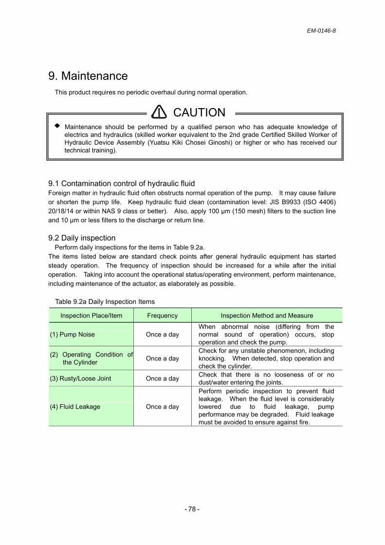
EM-0146-8
- - 78
9. Maintenance This product requires no periodic overhaul during normal operation.
9.1 Contamination control of hydraulic fluid Foreign matter in hydraulic fluid often obstructs normal operation of the pump. It may cause failure or shorten the pump life. Keep hydraulic fluid clean (contamination level: JIS B9933 (ISO 4406) 20/18/14 or within NAS 9 class or better). Also, apply 100 µm (150 mesh) filters to the suction line and 10 µm or less filters to the discharge or return line. 9.2 Daily inspection
Perform daily inspections for the items in Table 9.2a. The items listed below are standard check points after general hydraulic equipment has started steady operation. The frequency of inspection should be increased for a while after the initial operation. Taking into account the operational status/operating environment, perform maintenance, including maintenance of the actuator, as elaborately as possible.
Table 9.2a Daily Inspection Items
Maintenance should be performed by a qualified person who has adequate knowledge of electrics and hydraulics (skilled worker equivalent to the 2nd grade Certified Skilled Worker of Hydraulic Device Assembly (Yuatsu Kiki Chosei Ginoshi) or higher or who has received our technical training).
Inspection Place/Item Frequency Inspection Method and Measure
(1) Pump Noise Once a day When abnormal noise (differing from the normal sound of operation) occurs, stop operation and check the pump.
(2) Operating Condition of the Cylinder Once a day
Check for any unstable phenomenon, including knocking. When detected, stop operation and check the cylinder.
(3) Rusty/Loose Joint Once a day Check that there is no looseness of or no dust/water entering the joints.
(4) Fluid Leakage Once a day
Perform periodic inspection to prevent fluid leakage. When the fluid level is considerably lowered due to fluid leakage, pump performance may be degraded. Fluid leakage must be avoided to ensure against fire.
CAUTION

EM-0146-8
- - 79
9.3 Inspection of the AC servo motor Employing a brushless motor makes daily inspection of the AC servo motor easy. Use Table 9.3a for reference. Determine the appropriate inspection frequency in terms of the operational status/operating environment.
Table 9.3a Inspection of the AC Servo Motor 9.4 Guideline for replacing the AC servo motor components See Table 9.4a for component replacement intervals. The replacement period may vary depending on the condition of use or the operating environment. Replacement is required every time any failure is found. Contact the place of purchase or our customer support to request for component replacement. The requirement of component replacement will be determined after inspection.
Table 9.4a Component Replacement Intervals for the AC Servo Motor 9.5 Inspection of the AMSE controller
No daily inspection is required. Inspect the controller at least once a year. Table 9.5a Inspection of the AMSE Controller
9.6 Guideline for replacing the components of the AMSE controller The electric or electronic components of the AMSE controller are subject to mechanical wear and
aging. Periodically inspect them as part of preventive maintenance. Also, contact the place of purchase or our customer support according to Table 9.6a Component Replacement Intervals for the AMSE Controller. The requirement of component replacement will be determined after inspection. For the AMSE controller returned to/overhauled by us, parameter settings are reset to default values before shipment. Be sure to use the controller after setting the parameters appropriately.
Table 9.6a Component Replacement Intervals for the AMSE Controller
Inspection Place/Item Frequency Inspection Method and Measure
(1) Vibration and Acoustic Check Once a day
Comparing to normal conditions, check that there is no increase in vibration and noise by touch and by listening.
(2) External Inspection Depending on damage Clean with cloth or air, if required.
(3) Overall Check Once every 20000
hours or every 5 years Contact the place of purchase or our customer support
Inspection Place/Item Interval Inspection Method and Measure
(1) External Inspection Check that there is no dust, dirt, or oil contamination. If required, perform cleaning with cloth or air.
(2) Check for Loose Screws
Once a year (at least) Check for loose mounting screws for the terminal block
or connectors. If required, retighten them.
Component Replacement Interval Remarks (1) Bearing 20 thousand hours
(2) Cooling Fan 20 thousand hours
When any failure is found, replacement is required even before the specified interval is reached.
Component Standard Replacement Interval Remarks (1) Cooling Fan 10 years
(2) Main circuit smoothing capacitor
10 years (assuming the annual average ambient temperature of 40 °C)
(3) On-board smoothing capacitor 10 years
When any failure is found, replacement is required even before the specified interval is reached.
EM-0146-8
- - 80
10. Storage of unused units Store and manage unused and spare units in a proper indoor storage place.
Storage temperature range: 0 to 40 °C (no freezing) Storage humidity range: 80 % or less (no condensation) To avoid rust, corrosion, degradation of seals, etc., do not store the unit in the following and
similar places. a) Places potentially exposed to the direct influence of weather b) Places where chemicals, such as organic solvents, acids, and alkalis, are present or the
effect of vaporized gas potentially exists c) Places where dew condensation potentially occurs due to substantial temperature
fluctuations.
11. Disposal This unit is categorized as industrial waste for the purpose of disposal. When disposing of the
unit, its components, and hydraulic fluid, follow the procedures set out in the Waste Disposal and Public Cleansing Law and have them disposed of by an industrial waste disposal contractor.
12. Customer service If there are requests regarding our products or if any services are required, please contact the
place of purchase, our customer support, or the following sales department.
YUKEN KOGYO CO., LTD. International Sales Department
4-4-34, Kamitsuchidana-Naka, Ayase,
Kanagawa Pref. 252-1113, Japan
Phone +81-467-77-3111 Fax +81-467-77-3115
YUKEN EUROPE LTD. 51 Spindus Road,Speke Hall
Industrial Estate, Liverpool L24 1YA,
United Kingdom
Phone +44-151-486-4696 Fax +44-151-486-3537

EM-0146-8
- - 81
History of Publication ASE AC Servo Motor-Driven Pump Operation Manual
December 2009 First edition of the English version Pub. EM-0146
July 2013 9th edition of the English version Pub.EM-0146-8
Published by:
YUKEN KOGYO CO., LTD.
Products Publicity Section, Sales Administration Dept.
Hamamatsucho Seiwa Bldg., 4-8, Shiba-Daimon 1-Chome Minato-ku, Tokyo 105-0012, Japan Phone: +81-3-3432-2113 Fax: +81-3-3436-2344