"Curved extra-dimensions" by Nicolas Deutschmann (Institut de Physique Nucleaire de Lyon, France)

your ticket to all busesyour ticket to all buses
Instruction ManualUniversal Fieldbus-Gateway
UNIGATE® IC-CANopen®
Manual Art.-No.: V3252E
Deutschmann Automation GmbH & Co. KG | Carl-Zeiss-Str. 8 | D-65520 Bad CambergTel:+49 6434 9433-0 | Hotline: +49 6434 9433-33 | Fax: +49 6434 9433-40
www.deutschmann.com


Deutschmann Automation GmbH & Co. KG
1 General introduction . . . . . . . . . . . . . . . . . . . . . . . . 9
2 The UNIGATE® IC . . . . . . . . . . . . . . . . . . . . . . . . . 10
2.1 Technical introduction . . . . . . . . . . . . . . . . . . . . . . . 10
2.2 Availability . . . . . . . . . . . . . . . . . . . . . . . . . . . . . 10
2.3 Firmware . . . . . . . . . . . . . . . . . . . . . . . . . . . . . . 10
2.4 The serial standard interface . . . . . . . . . . . . . . . . . . . 10
2.5 The synchronous serial interface . . . . . . . . . . . . . . . . . 10
2.6 The Debug-interface . . . . . . . . . . . . . . . . . . . . . . . . 10
2.7 UNIGATE® IC hardware survey . . . . . . . . . . . . . . . . . . 11
3 Hardware design. . . . . . . . . . . . . . . . . . . . . . . . . . 12
3.1 Ports . . . . . . . . . . . . . . . . . . . . . . . . . . . . . . . . 12
3.2 Pinout . . . . . . . . . . . . . . . . . . . . . . . . . . . . . . . 123.2.1 -Boot enable . . . . . . . . . . . . . . . . . . . . . . . . . . . . . . 133.2.2 Load out (SPI-Master: SS0-) . . . . . . . . . . . . . . . . . . . . . 133.2.3 Data out (SPI-Master: SS1-) . . . . . . . . . . . . . . . . . . . . . . 133.2.4 Data In (SPI: MISO) . . . . . . . . . . . . . . . . . . . . . . . . . . 133.2.5 Load In (SPI: MOSI) . . . . . . . . . . . . . . . . . . . . . . . . . . 133.2.6 Clock (SPI: SCK) . . . . . . . . . . . . . . . . . . . . . . . . . . . 133.2.7 -Reset In . . . . . . . . . . . . . . . . . . . . . . . . . . . . . . . . 133.2.8 LED CANopen® . . . . . . . . . . . . . . . . . . . . . . . . . . . . 133.2.9 -Config Mode . . . . . . . . . . . . . . . . . . . . . . . . . . . . . 133.2.10 DbgTX, DbgRX . . . . . . . . . . . . . . . . . . . . . . . . . . . . 143.2.11 TE . . . . . . . . . . . . . . . . . . . . . . . . . . . . . . . . . . . 143.2.12 TX, RX . . . . . . . . . . . . . . . . . . . . . . . . . . . . . . . . . 14
3.3 Software . . . . . . . . . . . . . . . . . . . . . . . . . . . . . . 14
3.4 Basic line of proceeding . . . . . . . . . . . . . . . . . . . . . . 14
3.5 Connection examples . . . . . . . . . . . . . . . . . . . . . . . 15
3.6 Layout examples . . . . . . . . . . . . . . . . . . . . . . . . . . 18
3.7 Handling (mounting the UNIGATE® IC on the carrier board) . . . 20
4 The serial interface . . . . . . . . . . . . . . . . . . . . . . . . 21
4.1 Overview . . . . . . . . . . . . . . . . . . . . . . . . . . . . . . 21
4.2 Initialization of the serial interface . . . . . . . . . . . . . . . . . 21
4.3 Use of the serial interface . . . . . . . . . . . . . . . . . . . . . 21
4.4 Further operation modes . . . . . . . . . . . . . . . . . . . . . . 21
5 Synchronous serial interface . . . . . . . . . . . . . . . . . . . 22
5.1 Shift register operation . . . . . . . . . . . . . . . . . . . . . . . 225.1.1 Example-Script . . . . . . . . . . . . . . . . . . . . . . . . . . . . 22
28.9.15 Instruction manual UNIGATE® IC-CANopen® V. 2.8 3

Deutschmann Automation GmbH & Co. KG
5.2 SPI mode . . . . . . . . . . . . . . . . . . . . . . . . . . . . . . 235.2.1 Example-Script . . . . . . . . . . . . . . . . . . . . . . . . . . . . 23
6 The Debug-interface . . . . . . . . . . . . . . . . . . . . . . . . 24
6.1 Overview of the Debug-interface . . . . . . . . . . . . . . . . . . 24
6.2 Starting in the Debug-mode . . . . . . . . . . . . . . . . . . . . . 24
6.3 Communication parameter for the Debug-interface . . . . . . . . . 24
6.4 Possibilities with the Debug-interface . . . . . . . . . . . . . . . . 24
6.5 Commands of the Debug-interface . . . . . . . . . . . . . . . . . 24
7 Script and configuration . . . . . . . . . . . . . . . . . . . . . 25
7.1 Overview . . . . . . . . . . . . . . . . . . . . . . . . . . . . . . 25
7.2 The configuration mode . . . . . . . . . . . . . . . . . . . . . . . 25
7.3 Update the script . . . . . . . . . . . . . . . . . . . . . . . . . . 25
7.4 Configuration of the UNIGATE® IC . . . . . . . . . . . . . . . . . 277.4.1 CANopen® . . . . . . . . . . . . . . . . . . . . . . . . . . . . . . . 277.4.2 RS232/RS485/RS422 . . . . . . . . . . . . . . . . . . . . . . . . . 27
8 Generating a script . . . . . . . . . . . . . . . . . . . . . . . . 28
8.1 What is a script? . . . . . . . . . . . . . . . . . . . . . . . . . . 28
8.2 Memory efficiency of the programs . . . . . . . . . . . . . . . . . 28
8.3 What can you do with a script device? . . . . . . . . . . . . . . . 28
8.4 Independence of buses . . . . . . . . . . . . . . . . . . . . . . . 28
8.5 Further settings at the gateway . . . . . . . . . . . . . . . . . . . 28
8.6 The use of the Protocol Developer . . . . . . . . . . . . . . . . . 29
8.7 Accuracies of the baud rates at UNIGATE® IC . . . . . . . . . . . 29
8.8 Script processing times . . . . . . . . . . . . . . . . . . . . . . . 30
9 Firmware-update . . . . . . . . . . . . . . . . . . . . . . . . . . 31
9.1 Overview . . . . . . . . . . . . . . . . . . . . . . . . . . . . . . 31
9.2 Adjusting the firmware-update-mode . . . . . . . . . . . . . . . . 319.2.1 Adjustment by hardware . . . . . . . . . . . . . . . . . . . . . . . . 319.2.2 Adjustment by software . . . . . . . . . . . . . . . . . . . . . . . . 31
9.3 Execution of the firmware-update . . . . . . . . . . . . . . . . . . 31
9.4 Note on safety . . . . . . . . . . . . . . . . . . . . . . . . . . . . 31
9.5 Operation mode of the IC . . . . . . . . . . . . . . . . . . . . . . 31
10 Error handling at UNIGATE® IC . . . . . . . . . . . . . . . . . . 32
11 Technical data . . . . . . . . . . . . . . . . . . . . . . . . . . . 33
11.1 Mechanics of the UNIGATE® IC . . . . . . . . . . . . . . . . . . 3311.1.1 General dimensions of UNIGATE® IC . . . . . . . . . . . . . . . . . 33
4 Instruction manual UNIGATE® IC-CANopen® V. 2.8 28.9.15

Deutschmann Automation GmbH & Co. KG
11.1.2 Dimensions UNIGATE® IC-CANopen® . . . . . . . . . . . . . . . . 33
11.2 Technical data UNIGATE® IC-CANopen® . . . . . . . . . . . . . 3411.2.1 Performance characteristics of the different versions . . . . . . . . . 34
12 Accessory . . . . . . . . . . . . . . . . . . . . . . . . . . . . . 35
12.1 Adapter RS232 . . . . . . . . . . . . . . . . . . . . . . . . . . . 35
12.2 Adapter RS485 . . . . . . . . . . . . . . . . . . . . . . . . . . . 35
12.3 FirmwareDownloadTool (FDT) . . . . . . . . . . . . . . . . . . . 35
12.4 Protocol Developer . . . . . . . . . . . . . . . . . . . . . . . . . 35
12.5 Developerkit UNIGATE® IC-AB IC . . . . . . . . . . . . . . . . . 3512.5.1 Developerboard UNIGATE® IC-AB . . . . . . . . . . . . . . . . . . 3512.5.2 Quick start . . . . . . . . . . . . . . . . . . . . . . . . . . . . . . . 36
13 Appendix . . . . . . . . . . . . . . . . . . . . . . . . . . . . . . 37
13.1 Explanations of the abbreviations . . . . . . . . . . . . . . . . . 37
13.2 Basis board . . . . . . . . . . . . . . . . . . . . . . . . . . . . 3813.2.1 Overview basis board CANopen® . . . . . . . . . . . . . . . . . . . 3813.2.2 Connectors . . . . . . . . . . . . . . . . . . . . . . . . . . . . . . 42
13.2.2.1 Connector to the external device (RS-interface) . . . . . . . . . . . . . . . 42
13.2.2.2 CANopen®-connector . . . . . . . . . . . . . . . . . . . . . . . . . . . . 43
13.2.2.3 Power supply of the basis board . . . . . . . . . . . . . . . . . . . . . . . 43
13.2.2.4 Shield terminal lead . . . . . . . . . . . . . . . . . . . . . . . . . . . . . 43
13.2.2.5 Rotary coding switches . . . . . . . . . . . . . . . . . . . . . . . . . . . 43
13.2.2.6 Slide switch (RS485/RS232 interface) . . . . . . . . . . . . . . . . . . . . 43
13.2.2.7 Slide switch (RS485 termination) . . . . . . . . . . . . . . . . . . . . . . 43
13.2.3 Wiring diagrams UNIGATE® IC-basis board CANopen® . . . . . . . 44
14 Servicing . . . . . . . . . . . . . . . . . . . . . . . . . . . . . . 47
14.1 Downloading PC software and EDS-file, sample Scripts etc. . . . 47
15 EC declaration of conformity . . . . . . . . . . . . . . . . . . . 48
28.9.15 Instruction manual UNIGATE® IC-CANopen® V. 2.8 5

Deutschmann Automation GmbH & Co. KG
6 Instruction manual UNIGATE® IC-CANopen® V. 2.8 28.9.15

Deutschmann Automation GmbH & Co. KG
Disclaimer of liability
We have checked the contents of the document for conformity with the hardware and software described. Nevertheless, we are unable to preclude the possibility of deviations so that we are unable to assume warranty for full compliance. The information given in the publication is,however, reviewed regularly. Necessary amendments are incorporated in the following editions. We would be pleased to receive any improvement proposals which you may have.
CopyrightCopyright (C) Deutschmann Automation GmbH & Co. KG 1997 – 2015. All rights reserved.This document may not be passed on nor duplicated, nor may its contents be used or disclosed unless expressly permitted. Violations of this clause will necessarily lead to compensation in damages. All rights reserved, in particular rights of granting of patents or registration ofutility-model patents.
28.9.15 Instruction manual UNIGATE® IC - CANopen® V. 2.8 7

Deutschmann Automation GmbH & Co. KG
8 Instruction manual UNIGATE® IC - CANopen® V. 2.8 28.9.15

Deutschmann Automation GmbH & Co. KG General introduction
1 General introduction
In the past the integration of a fieldbus connection required an enormous effort from the progress engineers. On account of the large variety of communication systems it is not enough to compile the right combination of communication hardware; due to their standards and fundamentals dif-ferent busses also require the corresponding skills of the engineers.
This does not apply in case of the UNIGATE® IC by Deutschmann Automation any more. All dig-ital functions, software, stack and driver as well as optocoupler are integrated on a UNIGATE® IC in correspondence with the standard. In addition to the reduction of the required size, also differ-ent fieldbusses can easily be integrated.
Through the flexible firmware of UNIGATE® IC no software-changes are required on the side of the customer!
For almost a decade now Deutschmann Automation has experience in the field of fieldbus gateways; this enormous experience results in the UNIGATE® IC as a consistent sequel of this successful product line.
TerminologyIn the entire document and in all parts of the software that is to be used, the terms Input and Out-put are used. Input and Output are ambiguous, always depending on the viewpoint. We see the fieldbus as central interface and as integral component of your device; therefore in all places it is always referred to data from the viewpoint of the Slave, that is Input data, as data from the Mas-ter to the Slave - regardless of the used bus.
Representation of numbersNumbers in decimal format are always represented without prefix and without suffix as well. Hexadecimal numbers are always marked with the prefix 0x.
28.9.15 Instruction manual UNIGATE® IC - CANopen® V. 2.8 9

The UNIGATE® IC Deutschmann Automation GmbH & Co. KG
2 The UNIGATE® IC
2.1 Technical introduction
The UNIGATE® IC by Deutschmann Automation contains all components that are required for the communication in a fieldbus in one single module. Therefore a developer does not have to take care for that detail any more, only a hardware redesign is necessary in order to integrate the UNIGATE® IC and the required plug connectors.
2.2 Availability
The module is available as CANopen®. Further fieldbusses are either planned or being worked on. They will only differ in the connections of the busses. The meaning of the general pins 1 - 9 as well as 24 and 26 - 32 will remain unchanged also for further fieldbus implementations.You can find an up-to-date list for all UNIGATE® ICs under:http://www.deutschmann.com.
2.3 Firmware
UNIGATE® IC is programmed via scripts. On principle any script, that has been developed for a UNIGATE® SC, can also be operated on the UNIGATE® IC.
2.4 The serial standard interface
Intelligent devices, that already feature a micro controller or a microprocessor, are generally sup-plied with a serial asynchronous interface with a TTL-level. It is directly connected with the TTL-interface of the UNIGATE® IC. For more information on this serial interface see chapter 4.
2.5 The synchronous serial interface
In addition to the standard interface there is also the possibility of the synchronous input and out-put. That way for instance digital IOs can be connected through shift register components or also analog IOs can be connected through a DA-converter with serial in-/output. For synchronous IOs 256 signals at the most can be used (256 bit). In chapter 3.5 you can find wiring examples and software examples can be found in chapter 5. This interface can also be used to connect mod-ules or devices with SPI-interface. It is also possible to build, for instance digital or analogous I/O-modules, with the customer’s device not being equipped with an own controller. The fieldbus IC is also operable autonomously without that controller.
2.6 The Debug-interface
UNIGATE® IC features a Debug-interface, which allows to process a script step by step and also to monitor or manipulate data. This is indispensable for the development of a script. Usually a script is developed with the software Protocol Developer. For more details take a look at the instruction manual Protocol Developer.
All interfaces can independently be used at the same time.
10 Instruction manual UNIGATE® IC - CANopen® V. 2.8 28.9.15

Deutschmann Automation GmbH & Co. KG The UNIGATE® IC
2.7 UNIGATE® IC hardware survey
The hardware of the UNIGATE® IC consists of some few standard components. The picture below shows the functional structure of the IC.
UART 1 UART 2 SYN.SERIAL
Microcontroller
Flash-ROM
RAM
EEROM
DC DC
Opto Coupler
Fieldbus-Interface
Isolation
T E N
T X
R X
RX
T X
CLOCKLOAD OUT
DATA OUT
DATA IN
LOAD IN
28.9.15 Instruction manual UNIGATE® IC - CANopen® V. 2.8 11

Hardware design Deutschmann Automation GmbH & Co. KG
3 Hardware design
This chapter gives basic advise, that is required in order to load UNIGATE® IC into your own hardware designs. In the following all ports of UNIGATE® IC are described in detail.
3.1 Ports
UNIGATE® IC features 32 pins in its layout as a DIL 32 component. Pin 10 -12 as well as 21 - 23 are not wired due to the electrical isolation. The exact mechanical dimensions can taken from chapter 11.
In the layout boreholes for ALL 32 pins have to be planned.
3.2 Pinout
Pin Technicalspecifications
Name Description Remark
1* 5V ± 5%, < 270mA Vcc + 5 V voltage supply optionally 3,3V available2 INLogic -BE boot enable3 OUTDriver Load out
(SS0-)strobe signal of the output data of the synchronous, serial interface
4 OUTDriver Data out(SS1-)
output data for synchronous, serial interface
5 INLogic Data in(MISO)
input data of the synchronous, serial interface
internally pulled up with 10 k
6 OUTLogic Load in(MOSI)
strobe signal of the input data of the synchronous, serial interface
7 OUTDriver Clock(SCK)
clock pulse signal for synchronous, serial interface
8 INReset -Reset in reset-input of the IC internally pulled up with 100 k9* connected to pin 1 Vcc + 5 V voltage supply10-12 nc nc no pin existent13 according to norm CANL CANopen®-signal according to stan-
dardgalvanically isolated insulation voltage 1000 Vrms
14 according to norm CANH CANopen®-signal according to stan-dard
galvanically isolated insulation voltage 1000 Vrms
15-18 according to norm nc not connected19 according to norm CAN-GND CANopen® reference potential galvanically isolated
insulation voltage 1000 Vrms20 according to norm nc not connected21-23 nc nc no pin existent24* ccnnected to pin 32 GND ground supply voltage of the IC25 *) LED-CAN LED CANopen®26 INLogic -Config Mode signal to start the configuration
modeinternally pulled up with 10 k
27 OUTLogic DbgTX serial Debug TX28 INLogic DbgRX serial Debug RX internally pulled up with 10 k29 INLogic RX serial data RX internally pulled up with 10 k30 OUTLogic TX serial data TX31 OUTLogic TE transmit enable32* GND GND ground supply voltage of the IC
* The supply voltage is 5 V +/- 5 %, max. 270 mA DC (optionally 3,3V).The CANopen® signals are galvanically isolated. The insulation voltage is 1000 Vrms.
12 Instruction manual UNIGATE® IC - CANopen® V. 2.8 28.9.15

Deutschmann Automation GmbH & Co. KG Hardware design
VIL VIH VOL VOH
INReset < 0.3V / 5mA > 1.95V / 10µA OUTLogic < 0.6V / 1mA > 3.8V / 0.1mAINLogic < 0.8V / 0.5mA > 1.95V / 10µA OUTDriver < 0.33V / 4mA > 3.8V / 4mA
3.2.1 -Boot enable
The IC is started in the firmware update mode with the level GND during the power up process. See also chapter 9.
3.2.2 Load out (SPI-Master: SS0-)
Strobe signal for the synchronous serial interface. With this signal data is taken from the con-nected shift registers to the physical outputs.In SPI mode this Pin serves as a low-active Slave-Select-Signal.
3.2.3 Data out (SPI-Master: SS1-)
On this line data is output on the synchronous serial interface. The most significant bit of the data is output first.In SPI mode this Pin serves as a low-active Slave-Select-Signal.
3.2.4 Data In (SPI: MISO)
Data is read in on the synchronous serial interface via this signal. The most significant bit of the data is expected first.In SPI mode this Pin serves as data transfer from Slave to Master.
3.2.5 Load In (SPI: MOSI)
This pin is the strobe signal for the input data of the synchronous serial interface.In SPI mode this Pin serves as data transfer Master to Slave.
3.2.6 Clock (SPI: SCK)
This signal is the clock line for the synchronous serial interface. That signal is equally valid for data input and data output.
3.2.7 -Reset In
•A reset generator (Max 809) is on board; with it in the normal case the reset input is not required. In this case the reset input has to be connected with VCC, in order to avoid interfe-rences (see chapter 3.6).
• If the customer’s application has to initiate a reset of the UNIGATE® IC, then the reset input can also be connected with a reset output of the customer’s application instead of connecting it with VCC. Here all specifications of the reset signal, mentioned in chapter 3.2 have to be kept. The reset-impulse is supposed to last at least 10 ms.
3.2.8 LED CANopen®
A red LED can be connected to this line (see chapter 3.6).States:
•LED off = CANopen® in the state “Operational“
•LED flashing = CANopen® in the state “Prepared“ or “Preoperational“-> This LED can not be used in case of RS485-operation.
3.2.9 -Config Mode
If the pin has the level GND, then the IC starts in the configuration mode.
28.9.15 Instruction manual UNIGATE® IC - CANopen® V. 2.8 13

Hardware design Deutschmann Automation GmbH & Co. KG
3.2.10 DbgTX, DbgRX
They are transmission line (TX) and receive line (RX) as well of the IC’s Debug-interface. For the function description of the Debug-interface see chapter 6.
3.2.11 TE
The transmit enable signal allows the connection of RS485 drivers to the IC’s serial interface. The signal is set to High whenever the IC sends via the line TX.
3.2.12 TX, RX
Transmission (TX) and receive line (RX) of the serial interface. This interface is programmable in accordance with the description in chapter 4.
3.3 Software
The software executes script-commands, which in turn control the IC’s hardware and they pro-cess their complete protocol by software. The script itself can be generated by the company Deutschmann Automation or with the software Protocol Developer by yourself. For a detailed description of the script commands of the Protocol Developer see the instruction manual Protocol Developer and the online documentation concerning script-commands.
3.4 Basic line of proceeding
In theory it is enough to replace the RS232-driver that is included in your application by the UNIGATE® IC.
.. . . .. .. .
Customer Processor
U A R T
Max 232
9-pol DSUB RS232
14 Instruction manual UNIGATE® IC - CANopen® V. 2.8 28.9.15

Deutschmann Automation GmbH & Co. KG Hardware design
Your device, which on the whole is supposed to be assembled as shown above, will now be mod-ified in a way that the CANopen® is available at the 9-pol. socket. However, a hardware redesign is necessary in order to keep the assignment in standard form.
After the RS232-driver has been replaced by the UNIGATE® IC, CANopen® is available at the 9-pol. D-sub-socket.Deutschmann Automation is also offering an appropriate adapter board. With it existing devices can be adapted without re-design; see chapter 12.
3.5 Connection examples
Here you will find some advise that offers help for a re-design. In the following several versions are listed, that should make it easier for you to decide.
Version 1: Use as a pure link module for the bus
The UNIGATE® IC independently processes the communication with the customer’s device via the TTL-interface.
28.9.15 Instruction manual UNIGATE® IC - CANopen® V. 2.8 15
Hardware design Deutschmann Automation GmbH & Co. KG
Version 2: Use of UNIGATE® IC for digital or analog I/O-modules
Here only the synchronous serial interface is used, the asynchronous serial interface is basically of no account. If you want to program the script in your completed application, then the use of a connector for the asynchronous interface is recommended. With it you can carry out the ISP-pro-gramming.For this operating mode no additional controller is required on your application!
16 Instruction manual UNIGATE® IC - CANopen® V. 2.8 28.9.15

Deutschmann Automation GmbH & Co. KG Hardware design
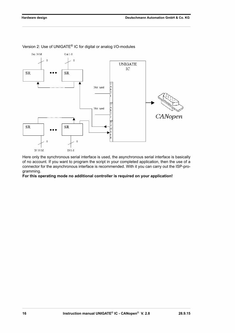
The following circuit diagram is an example for how shift register components can be connected to the IC.
Version 3: Example for digital I/OsThe serial synchronous and the asynchronous interface as well can be operated by UNIGATE®
IC at the same time. Here the possibility results that an existing application can be extended by additional digital or analog I/Os.In chapter 5.2 you find an example for a script, that operates these I/Os.
Valid for all versions: A planed plug connection of the serial interface in the application offers the possibility of an update of the firmware or the software via an external connection.
28.9.15 Instruction manual UNIGATE® IC - CANopen® V. 2.8 17

Hardware design Deutschmann Automation GmbH & Co. KG
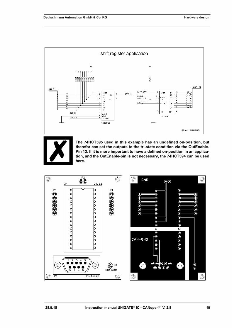
3.6 Layout examples
18 Instruction manual UNIGATE® IC - CANopen® V. 2.8 28.9.15
Deutschmann Automation GmbH & Co. KG Hardware design
The 74HCT595 used in this example has an undefined on-position, but therefor can set the outputs to the tri-state condition via the OutEnable-Pin 13. If it is more important to have a defined on-position in an applica-tion, and the OutEnable-pin is not necessary, the 74HCT594 can be used here.
28.9.15 Instruction manual UNIGATE® IC - CANopen® V. 2.8 19

Hardware design Deutschmann Automation GmbH & Co. KG
3.7 Handling (mounting the UNIGATE® IC on the carrier board)
Depending on the application and the expected shock- and vibration-conditions you can choose from the following possibilities for the UNIGATE® IC’s installation on the carrier board:
•Mounting on a socket in the carrier board. If necessary solder the UNIGATE® IC to 2 or 4 pins in the socket. Normally the IC can easily be pulled out after the soldering points have been re-moved.
•Make arrangements for two holes next to the socket in the layout. After the UNIGATE® IC was plugged in the socket pull an isolated wire over the IC and solder it on the carrier board at the specified holes.
• Fasten the UNIGATE® IC With a wire or a tie wrap on the socket. •Manual soldering directly on the carrier board.•Automatic soldering directly on the carrier board, whereas „selective“ soldering is essential (no
wave soldering)
The advantage of the socketed variant is the easy download of Script- and Firmware-updates, if the carrier board is not designed for it. Besides, that way the Fieldbus can be changed easily by changing the UNIGATE® IC if the corresponding plug connectors are provided on the carrier board. Another advantage is, that - normally - only a reflow soldering of the carrier board is ne-cessary.
The advantage of the soldered variant is, that the installation height is lower and a higher shock- and vibration-safety is provided.
20 Instruction manual UNIGATE® IC - CANopen® V. 2.8 28.9.15

Deutschmann Automation GmbH & Co. KG The serial interface
4 The serial interface
4.1 Overview
The serial interface is the most important connection between the UNIGATE® IC and the micro controller of your application. The interface is designed in a way so that your application at least does not have to be changed on the software-side. The wide range of services of the UNIGATE®
IC’s serial interface constitutes the basis for it. The UNIGATE® IC allows to connect of controllers with a baudrate of 110 baud to 625 kbaud. The baudrate for the communication itself is perma-nently stored in the module. The maximum size for IO-data can be read-out with the Script com-mand “Get RSOutBufFree16“.Depending on the downloaded Script of the UNIGATE® IC, the module carries out actions inde-pendently, in order to identify data from the connected device. For customers who already have a software-adaptation at he company Deutschmann Automation, this protocol as well as a Script after an adaptation can be processed by the IC.Anyway, the IC will take over the communication with the fieldbus independently.
4.2 Initialization of the serial interface
The initialization of the interface is carried out by script-commands, such as “Set baudrate“, “Set databits“, “Set parity“. For a detailed description of these commands see the online documentation for the Protocol Developer.
4.3 Use of the serial interface
The serial interface can freely be programmed by the user. Efficient script-commands for sending and receiving data are available; just to mention some possibilities: such as waiting with timeout for a character, waiting for a fixed number of characters or also sending and receiving data in the Modbus RTU. A reference to these commands is offered in the online documentation for the Protocol Developer.
4.4 Further operation modes
In the modes configuration mode and firmware-update mode the serial interface also serves to configure the standard software or to carry out a firmware-update. More details can be found in chapter 9.5.
28.9.15 Instruction manual UNIGATE® IC - CANopen® V. 2.8 21

Synchronous serial interface Deutschmann Automation GmbH & Co. KG
5 Synchronous serial interface
The synchronous serial interface of the UNIGATE® IC is used to connect clocked shift registers
or components that have a Serial Peripheral Interface (SPI).It allows
• the expansion of the IC for digital inputs and outputs (for example for driving LEDS or for
reading switch positions)
• communicate with microcontrollers or
• the control of DA and AD converters.
Connection examples are give in chapter 3.
By using the synchronous serial interface can realize products that can work without another
microcontroller (stand-alone mode). Examples are sensor products or digital IO modules
5.1 Shift register operation
Before the interface can be used, it has to be initialized by setting various Script parameters.
(see chapter 5.1.1)
The parameters „ShiftRegisterInputType“ and „ShiftRegisterOutputType“ allow the
use of different shift register types, which differ in the polarity of the shift register signals. To use
the shift register types 74595 and 74165, for example, the values „RiseClk_RiseLoad“ and
„RiseClk_LowLoad“ can be set.The shift register width is set by the parameter „ShiftRegisterInputBitLength“ and
„ShiftRegisterOutputBitLength“ The maximum width is 256 bits.The data exchange with the connected shift registers ensues with the commands
„WriteShiftRegister“, „ReadShiftRegister“ or bidirectional with the command „Shift-RegisterDataExchange“. The clock rate is between 280 kHz and 320 kHz.Further information on the commands and parameter values can be found in the Help section of
the Protocol Developer Software. On request, the Deutschmann Script language can be comple-
mented by additional parameter values in order to support other types of shift registers.
5.1.1 Example-Script
Note: The script example refers to the circuit example in chapter 3.5.
var InBuffer: Buffer[2];
var OutBuffer: Buffer[2];
MoveConst( OutBuffer[0], #0x58#0x21 );
Set( ShiftRegisterInputType, RiseClock_FallLoad );
Set( ShiftRegisterOutputType, RiseClock_RiseLoad );
22 Instruction manual UNIGATE® IC - CANopen® V. 2.8 28.9.15

Deutschmann Automation GmbH & Co. KG Synchronous serial interface
Set( ShiftRegisterInputBitLength, 16 );
Set( ShiftRegisterOutputBitLength, 16 );
WriteShiftRegister( OutBuffer[0] );
ReadShiftRegister( InBuffer[0] );
// Input data is now in the INBuffer
// 0x58 is applied to the outputs of the analog converter
// 0x21 at the shift register‘s outputs
5.2 SPI mode
Before the interface can be used in SPI mode, this must be initialized. The command InitSPIsets the operating type, the mode (signal polarity and phase) and the clock frequency.The data exchange ensues with the command ExchangeSPI. The maximum clock frequency is between 1 and 5 MHz, depending on the hardware. For details please see the IC-Pinout list in the download area of our website. Please also refer to the script commands documentation in the online help of the Protocol Developer.
5.2.1 Example-Script
var L_Freq : long;
var b_Channel : byte;
var w_Len : word;
var a_BufOut : buffer[100];
var a_BufIn : buffer[100];
moveconst( L_Freq, 1000000); // 1 MHz
InitSPI( 1 , 0 , L_Freq );
moveconst( b_Chanel, 0 );
moveconst( w_Len, 11 );
moveconst( a_BufOut[0], "Hello World" );
ExchangeSPI( b_Channel , w_Len , a_BufOut[0] , a_BufIn[0] );
28.9.15 Instruction manual UNIGATE® IC - CANopen® V. 2.8 23

The Debug-interface Deutschmann Automation GmbH & Co. KG
6 The Debug-interface
6.1 Overview of the Debug-interface
The UNIGATE® IC features a Debug-interface, that allows a step-by-step processing of a script. Normally this interface is only required for the development of a script.
6.2 Starting in the Debug-mode
When applying power to the UNIGATE® IC (power up) the firmware will output the binary character 0 (0x00) after a self-test was carried out on this interface. If the IC receives an acknowledgement via this interface within 500 ms, it is in the Debug-mode. The acknowledgement is the ASCII-character O (0x4F). With the start in the Debug-mode the further execution of script-commands will be put to a stop.
6.3 Communication parameter for the Debug-interface
The Debug-interface is always operating with 9600 baud, no parity, 8 data bit, 1 stop bit. It is not possible to change this parameter in the Protocol Developer. Please note that these settings cor-respond to those of the PC-COM-interface and that the flow control (protocol) is set on “None“ there.
6.4 Possibilities with the Debug-interface
Usually the Protocol Developer is connected to the Debug-interface. With it a step-by-step pro-cessing of a script, monitoring jumps and decisions and looking at memory areas is possible. Moreover breakpoints can be set. It basically possesses all characteristics a software-develop-ment tool is typically supposed to have. However, it is also possible to carry out a Scrip-update via this interface.
6.5 Commands of the Debug-interface
The commands for the use of the Debug-interface are described in the instruction manual Protocol Developer.
24 Instruction manual UNIGATE® IC - CANopen® V. 2.8 28.9.15

Deutschmann Automation GmbH & Co. KG Script and configuration
7 Script and configuration
7.1 Overview
The script stored in the UNIGATE® IC, as well as the configuration, can be replaced or updated via the serial interface (application) in the configuration mode.
7.2 The configuration mode
If the pin „ConfigMode“ pulled to GND during the PowerUp or Reset, then the UNIGATE® IC starts in the configuration mode. In this mode it is possible to communicate with the IC without processing the regular software. In this mode it is possible to change the UNIGATE® IC’s settings of the standard software or to write a new script in the UNIGATE® IC. It shows its start in the con-figuration mode by issuing a status message, which might look as follows:IC-CO-SC V5.02[25] (c)dA Script(8k)="Leer" Author="Deutschmann Automation GmbH" Version="1.0" Date=21.08.2001 SN=47110001
7.3 Update the script
• The preferred option is to insert the UNIGATE® IC into the base board from Deutschmann
(Developer Board UNIGATE® IC-AB) and use the Deutschmann tools (software WINGATE with „Write Script“ under „File“ or with the software ScriptProgramTool).
•Your host can also automatically replace the script in your application. In the following flow chart the handshake is shown.
28.9.15 Instruction manual UNIGATE® IC - CANopen® V. 2.8 25

Script and configuration Deutschmann Automation GmbH & Co. KG
26 Instruction manual UNIGATE® IC - CANopen® V. 2.8 28.9.15

Deutschmann Automation GmbH & Co. KG Script and configuration
The operational sequence is as follows: The Gateway has to be in the config-mode.The script-download is initiated with "Ctrl-P (=0x10)".After that the data follows byte by byte as ASCII-hex-characters.The download is terminated with a "LF (=0x0A)". Afterwards the word-checksum follows as ASCII-hex-characters. The Gateway responds with a clear text reply to that download and carries out a warm start. Example:The following 4-bytes script is supposed to be downloaded: 0x01 0x12 0x5A 0x23The sum of the bytes is 0x0090 as checksum.Then the following sequence is to be sent: 1. 0x10 Ctrl-P2. 0x30 '0'3. 0x31 '1'4. 0x31 '1'5. 0x32 '2' 6. 0x35 '5'7. 0x41 'A' 8. 0x32 '2'9. 0x33 '3'10. 0x0A LF11. 0x30 '0'12. 0x30 '0'13. 0x39 '9'14. 0x30 '0' Gateway’s reply: "Download ok"
7.4 Configuration of the UNIGATE® IC
UNIGATE® is delivered with an empty script.The configuration of the UNIGATE® IC - CANopen® is restricted to the setting of the fieldbus address.
7.4.1 CANopen®
•NODE-ID: in accordance with script setting or configuration data•CAN baud rate: in accordance with script
7.4.2 RS232/RS485/RS422
•RS-type: RS232•Start bit: 1•Data bits: 8 •Stop bit: 1•Parity: None•Baud rate: 9600 BaudDefault-setting. This configuration can be changed via the Script.
28.9.15 Instruction manual UNIGATE® IC - CANopen® V. 2.8 27

Generating a script Deutschmann Automation GmbH & Co. KG
8 Generating a script
8.1 What is a script?
A script is a sequence of commands, that are executed in that exact order. Because of the fact that also mechanisms are given that control the program flow in the script it is also possible to assemble more complex processes from these simple commands. The script is memory-oriented. It means that all variables always refer to one memory area. While developing a script you do not have to take care of the memory management though. The Protocol Developer takes on this responsibility for you.
8.2 Memory efficiency of the programs
A script command can carry out e. g. a complex checksum like a CRC-16 calculation via data. For the coding of this command only 9 byte are required as memory space (for the command itself). This is only possible when these complex commands are contained in a library.A further advantage of this library is, that the underlying functions have been in practical use for a couple of years and therefore can be described as ’void of errors’. As these commands are also present in the native code for the controller, at this point also the runtime performance of the script is favorable.
8.3 What can you do with a script device?
Our script devices are in the position to process a lot of commands. In this case a command is always a small firmly outlined task. All commands can be put into classes or groups. A group of commands deals with the communication in general. This group’s commands enable the gate-way to send and receive data on the serial side as well as on the bus-side.
8.4 Independence of buses
Basically the scripts do not depend on the bus, they are supposed to operate on. It means that a script which was developed on a PROFIBUS gateway can also be operated on an Interbus with-out changes, since the functioning of these buses is very similar. In order to also process this script on an EtherNet gateway, perhaps further adjustments have to be made in the script, so that the script can be executed reasonably.There are no fixed rules how which scripts have to operate properly. When writing a script you should take into account on which target hardware the script is to be executed, so the necessary settings for the respective buses can be made.
8.5 Further settings at the gateway
Most devices require no further adjustments, except for those made in the script itself. However, there are also exceptions to it. These settings are made by means of the software WINGATE. If you know our UNIGATE®-series, you are already familiar with the proceeding with it. An example is the adjustment of the IP-address and the net-mask of an EtherNet-gateway. These values have to be known as fixed values and are not available for the runtime. Another reason for the configuration of the values in WINGATE is the following: After an update of the script these val-ues remain untouched, i. e. the settings that were made once are still available after a change of the script.Only this way it is also possible that the same script operates on different EtherNet-gateways, that feature different IP-addresses.
28 Instruction manual UNIGATE® IC - CANopen® V. 2.8 28.9.15

Deutschmann Automation GmbH & Co. KG Generating a script
8.6 The use of the Protocol Developer
The Protocol Developer is a tool for an easy generation of a script for our script gateways. Its operation is exactly aimed at this use. After starting the program the script that was loaded the last time is loaded again, provided that it is not the first start.Typical for Windows script commands can be added by means of the mouse or the keyboard. As far as defined and required for the corresponding command, the dialog to the corresponding command is displayed, and after entering the values the right text is automatically added to the script. The insertion of new commands by the Protocol Developer is carried out in a way that existing commands will not be overwritten. Generally a new command is inserted in front of the one where the cursor is positioned. Of course the commands can also be written by means of the keyboard or already written commands can also be modified.
8.7 Accuracies of the baud rates at UNIGATE® IC
The baud rate of the serial interface is derived from the processor’s crystal frequency.Meanwhile all Script-gateways are working with a crystal frequency of 40 MHz.You can enter any desired integer baud rate into the script. After that the firmware adjusts the baud rate, that can be derived the most precisely from the crystal frequency.The baud rate the gateway is actually working with (BaudIst) can be determined as follows:
BaudIst = (F32 / K)F32 = Crystal frequency [Hz] / 32K = Round (F32 / BaudSoll);
Round () is a commercial roundoff
Example:The actual baud rate is to be calculated, when 9600 baud are pre-set, where the gateway is operated with 40 MHz:
F32 = 40000000 / 32 = 1250000K = Round(1250000 / 9600) = Round(130.208) = 130BaudIst = 1250000 / 130 = 9615.38
I. e.: The baud rate actually adjusted by the gateway is 9615.38 baud
The resulting error in per cent can be calculated as follows:
Error[%] = (abs(BaudIst - BaudSoll) / BaudSoll) * 100
In our example the following error results:Error = (abs(9615.38 - 9600) / 9600) * 100 = 0.16%
In practise errors below 2% can be tolerated!
In the following please find a listing of baud rates at a 40 MHz-crystal frequency with the corre-sponding errors:
28.9.15 Instruction manual UNIGATE® IC - CANopen® V. 2.8 29

Generating a script Deutschmann Automation GmbH & Co. KG
4800 baud: 0.16%9600 baud: 0.16%
19200 baud: 0.16%38400 baud: 1.35%57600 baud: 1.35%62500 baud: 0%
115200 baud: 1.35%312500 baud: 0%625000 baud: 0%
8.8 Script processing times
The Script is translated by the Protocol Developer and the consequently generated code is loaded into the Gateway. Now the processor in the Gateway interprets this code. In this case, there are commands that can be processed very fast (e. g. "Set Parameter"). There are also commands, however, that take longer (e. g. copying 1000 bytes). Consequently, for one thing the processing time differs due to the kind of Sript command. But the processing time of the Script commands is considerably more determined by the processor time that is available for this pro-cess. Since the processor has to carry out several tasks simultaneously (multitasking system) only a part of the processor's capacity is available for the Script processing. The following tasks - in the order of priority - are executed on the processor:
•Sending and receiving data at the Debug-interface (provided that the Protocol Developer has been started on the PC)
•Sending and receiving data at the RS-interface•Sending and receiving data at the Fieldbus-interface• Tasks controlled via internal clock (1 ms) (e. g. flashing of an LED)•Processing of the Script From experience approximately 0.5 ms can be calculated for each Script line. This value con-firmed itself again and again in many projects as a standard value. He is always quite right if the processor has enough time available for the Script processing. By means of the tasks mentioned above, the following recommendation can be formulated in order to receive a rather fast Script processing: •Deactivate the Debug-interface (it is the normal case in the serial use)•Keep the data length at the RS-interface as small as possible. The baud rate is not the problem
here, but the amount of characters which are transfered per second.•Do not unnecessarily extend the data length at the Fieldbus side. Especially at acyclical bus
data, if possible do only send them when changes were made. The data length at buses that are configured to a fixed length (e. g. PROFIBUS) should not be longer than absolutely neces-sary.
If the processing time should be too large in spite of these measures, there is the possibility to generate a customized Script command, that executes several tasks in one Script command.Please contact our support department for this purpose.
30 Instruction manual UNIGATE® IC - CANopen® V. 2.8 28.9.15

Deutschmann Automation GmbH & Co. KG Firmware-update
9 Firmware-update
9.1 Overview
UNIGATE® IC has a 64 kbyte flash memory for the firmware. In the firmware-update-mode the
firmware can be replaced via the UNIGATE® IC’s serial interface.
9.2 Adjusting the firmware-update-mode
9.2.1 Adjustment by hardware
UNIGATE® IC can be brought to the firmware-update-mode by the hardware. For it the signal BE(boot enable) has to be pulled to the potential GND during the Power-up-process.
9.2.2 Adjustment by software
If the UNIGATE® IC is in the configuration mode (see chapter 7.2) it can be brought to the firm-ware-update-mode interactively through the command CTRL-F (0x06). After sending the com-mand a security query follows, that has to be answered with J or N (J = Yes, N = No). After a positive confirmation the IC is re-started in the firmware-update-mode.
9.3 Execution of the firmware-update
The safest way for the firmware-update is the use of the basis board combined with the software “FDT.EXE“ (firmware-download-tool). These tools are available from Deutschmann Automation (see chapter 12).
9.4 Note on safety
The firmware-update should only be carried out when there is no other possibility left. A firm-ware-update-process that has already been started CANNOT be undone. With it the previously used firmware is permanently unusable.
9.5 Operation mode of the IC
Standard-operation modeThis mode is required for the regular use of the IC. In this mode the IC will process all script-com-mands and normally exchange the corresponding user data. The bus as well is operated in this mode through the IC.
Configuration mode
In the configuration mode the UNIGATE® IC will carry out a self-test after the start (or after a reset). After a successful self-test it will wait for further commands. Here it is possible to load a translated script into the unit or to initialize the firmware-download-mode.
28.9.15 Instruction manual UNIGATE® IC - CANopen® V. 2.8 31

Error handling at UNIGATE® IC Deutschmann Automation GmbH & Co. KG
10 Error handling at UNIGATE® IC
If the Gateway detects an error, this error numer is sent as emergency telegram via CANopen®. The code 61xx (hex), that indicates an internal Firmware error according to DS301 is used for it. The current error code is entered for “xx“ in accordance with the below table. A detail error, that is used for internal purposes may still be included in byte 3 and 4 of the emergency message.A distinction can be made between two categories of system-errors:Serious errors (1-4): In this case, the Gateway must be switched off and switched back on again. If the error occurs again, the Gateway must be exchanged and returned for repair. Warnings (6-15): These warnings are displayed for one minute simply for information purposes and are then automatically reset. If such warnings occur frequently, please inform After-Sales Service.The system-error can be read-out via the Script.Error 10 is additionally activated in case of the heartbeat-error.
In the configuration mode these displays are not valid and only meant for internal use.
Error no. Error description0 Reserved1 Hardware fault2 EEROM error3 Internal memory error4 Fieldbus hardware error or wrong Fieldbus-ID5 Script error6 Reserved7 RS-transmit buffer overflow8 RS-receive buffer overflow9 RS timeout10 General fieldbus error11 Parity-or frame-check-error12 Reserved13 Fieldbus configuration error14 Fieldbus data buffer overflow15 Reserved
Table 1: Error handling at UNIGATE® IC
32 Instruction manual UNIGATE® IC - CANopen® V. 2.8 28.9.15

Deutschmann Automation GmbH & Co. KG Technical data
11 Technical data
In this chapter you will find all necessary technical data on UNIGATE® IC.All measurements in mm.
11.1 Mechanics of the UNIGATE® IC
11.1.1 General dimensions of UNIGATE® IC
11.1.2 Dimensions UNIGATE® IC-CANopen®
The pins of UNIGATE® IC are arranged with a grid spacing of 2.54 mm.
DIP-Spacing Code 6In case you intend to use other fieldbus ICs, the maximum overall height of 20 mm (including pins) has to be taken into consideration.
28.9.15 Instruction manual UNIGATE® IC - CANopen® V. 2.8 33

Technical data Deutschmann Automation GmbH & Co. KG
11.2 Technical data UNIGATE® IC-CANopen®
Characteristics ExplanationsSupply voltage 5 V ± 5 %, max. 270 mA DC (optionally 3,3V, see chapter 11.2.1)Interface 2 UART interfaces, 1 synchronous serial interfacePhysical separation-fieldbus-side StandardFieldbus-IDFieldbus-baud rate
Adjustable (via script)Up to 1MBaud (adjustable via script)
UART-baud rate Up to 625 Kbaud (adjustable via script)Technology SJA1000Others E. g. digital I/Os, analogue signals, shift registers , LEDs, switches, etc.
can be connected externallyDimensions 45 x 25 x 12 mm (WxDxH)Installation 32DILWeight Approx. 10 gOperating temperature -40°C ..+85°CStorage / transport temperature -40°C..+125°CBuilt-in position Any
11.2.1 Performance characteristics of the different versions
Performance characteristics
UNIGATE IC-CANopen4C4
UNIGATE IC-CANopen4C4X
Additional support - LSS, Script can read all objects (also 1xxxH)Additional supported objects - 1002 H / 1004 H / 1010 H / 1011 H / 1201 HMemory for Script code 12 K 16 KNumber Rx-PDO 16 32Number Tx-PDO 16 32Tx-PDO‘s with same object 2 8Number SDO 1 2Number user objects 255 65535Check object range - On write by SDONumber Heartbeatmoni-toring
3 32
CAN-Layer 2 Support by Script
yes yes
SDO-Block-Transfer - yesNumber errors in errorfield 2 10Deutschmann order no. 5 Volt V3491
3,3 Volt n.a.5 Volt V37863,3 Volt V3758
34 Instruction manual UNIGATE® IC - CANopen® V. 2.8 28.9.15

Deutschmann Automation GmbH & Co. KG Accessory
12 Accessory
The following tools are available from Deutschmann Automation.
12.1 Adapter RS232
In an application the adapter RS232 offers the possibility to replace an existing driver MAX 232 (only in DIL-16-housing) by this adapter. This board allows the use of the IC according to chapter 3.4 on page 14. Please note that with it the CANopen® does not offer a connection conforming to the standards. With a plug adapter, however, at least the operation of CANopen® is possible.The hardware is only meant for development purposes. It offers the possibility to make an existing application capable for bus connection in no time and to test the IC’s utilizability and functionality.
12.2 Adapter RS485
From the functionality’s point of view the RS485 adapter is the same as the RS232 adapter. It offers the possibility to replace a module LS 176 (only in DIL-8-housing) by the IC.There are the same restrictions as for the RS232 adapter.
12.3 FirmwareDownloadTool (FDT)
The FirmwareDownloadTool is available for download from our homepage. It is required for an update of the firmware. Condition for it is, that the software can be connected to the serial inter-face of the IC. The software describes the procedure of an update itself.
12.4 Protocol Developer
The Protocol Developer is the development environment for scripts, that also contain the Debug-ger. This software package also contains the documentation to all script-commands. This soft-ware is available for download from our homepage at http://www.deutschmann.de.The instruction manual for the Protocol Developer, which is available in pdf-format, gives further advise on how to use the software.
12.5 Developerkit UNIGATE® IC-AB IC
The Devloperkit IC contains
• a Developerboard UNIGATE® IC (see chapter 12.5.1)• a plug-in power pack to supply the Developerboard • connection cables for appl. RS232, Debug RS232 and appl. RS422/485•USB-cable•Software and documentation to complete the packet.
12.5.1 Developerboard UNIGATE® IC-AB
The Developer Board was developed so that the fast implementation of the Deutschmann All-in-one bus node UNIGATE® IC into your electronic system can be guaranteed. The board is suit-able for all Fieldbuses and Industrial Ethernet Buses supported by Deutschmann Automation.
28.9.15 Instruction manual UNIGATE® IC - CANopen® V. 2.8 35

Accessory Deutschmann Automation GmbH & Co. KG
The required UNIGATE® IC / ICs are ordered separately. The required voltage (5V or 3.3V, depending on the version) can be adjusted. An RS232-interface or a USB-connection is avail-able for the connection to the PC (Debug-interface).The application can be connected either through the USB, RS232, RS485 or the RS422.The bus-connections according to standard or market standard are available to test the respec-tive bus-side. Optionally Deutschmann Add-on packages (bus-master simulation) are available.The board contains 32 bit input and 16 bit output, provided with one LED each. Different connec-tors allow an easy coupling to your processor. A hole matrix field with the most important signals (voltage, IOs) allows a customized hardware extension (e. g. to connect a D/A converter).
12.5.2 Quick start
For a transparent data exchange you will find example scripts for the respective Fieldus under "File->New" in the Protocol Developer.
36 Instruction manual UNIGATE® IC - CANopen® V. 2.8 28.9.15

Deutschmann Automation GmbH & Co. KG Appendix
13 Appendix
13.1 Explanations of the abbreviations
GeneralCL = Product group CL (Compact Line)CM = Product group CM (CANopen Line)CX = Product group CXEL = Product group EL (Ethernet Line)FC = Product group FC (Fast Connect)GT = Galvanic separation RS-sideGY = Housing color grayMB = Product group MB
RS = Product group RSSC = Product group SC (Script)232/485 = Interface RS232 and RS485 switchable232/422 = Interface RS232 and RS422 switchableDB = Additional RS232 DEBUG-interfaceD9 = Connection of the RS through 9-pin D-SUB instead of 5-pin screw-plug connector PL = Board only without DIN-rail module and without housing cover PD = Board only without DIN-rail module and with housing cover AG = Gateway installed in a die-cast aluminum housing EG = Gateway installed in a stainless steel housing
IC = Product group IC (IC-design DIL32)IO8 = Option I/O816 = Script memory expanded to 16KB5V = Operating voltage 5V3,.3V = Operating voltage 3.3V
FieldbusASI = AS-Interface (AS-i)BI = BACnet/IPBMS = BACnet MSTBCO = CANopenC4 = CANopen V4
C4X = CANopen V4-version X (see comparison table UNIGATE® IC for the respectiveproduct)
DN = DeviceNetEC = EtherCATEI = Ethernet/IPFE = Ethernet 10/100 MBit
FEX = Ethernet 10/100 MBit-version X (see comparison table UNIGATE® IC for therespective product)
IB = InterbusIBL = InterbusLN62 = LONWorks62LN512 = LONWorks512ModTCP = ModbusTCP
MPI = Siemens MPI®
PL = Powerlink
28.9.15 Instruction manual UNIGATE® IC - CANopen® V. 2.8 37

Appendix Deutschmann Automation GmbH & Co. KG
PN = Profinet-IOPBDP = ProfibusDP
PBDPL = ProfibusDP-version L (see comparison table UNIGATE® IC for the respectiveproduct)
PBDPX = ProfibusDP-version X (see comparison table UNIGATE® IC for the respectiveproduct)
PBDPV0 = ProfibusDPV0PBDPV1 = ProfibusDPV1RS = Serial RS232/485/422
13.2 Basis board
The basis board that is descibed in this chapter was supplied until the end of 2008.A new board is available since the beginning of 2009 (see chapter 12.5.1).
13.2.1 Overview basis board CANopen®
38 Instruction manual UNIGATE® IC - CANopen® V. 2.8 28.9.15

Deutschmann Automation GmbH & Co. KG Appendix
Slot X 1 (ZIF-socket)PIN 1 of the IC is located up at the lever of the ZIF-socket.Never place the IC into the socket back to front!
P 2
Pin SignalPin 1 24 V DCPin 2 Ground
The basis board is supplied with voltage through this plug connector.
P 4 Earth terminal 6.3 mm for basis board.
P 7This plug is the basis board’s serial connection to the customer’s device and the connection to the PC (Debug-interface).For the pin assignment see chapter 13.2.2.1.
P 8
The illustration shows the arrangement of the pins. On this connector strip the signals of the serial connection between IC and RS-drivers are wired. For an initial development you will prob-ably also use an existing driver in your application. In order to exchange it later on, you can also directly take the signals of the serial interface here.
P 10
CANopen® plug connector: Pn assignment of the connector see chapter 13.2.2.2.
P 11
28.9.15 Instruction manual UNIGATE® IC - CANopen® V. 2.8 39

Appendix Deutschmann Automation GmbH & Co. KG
Force Boot. By setting this bridge the Pin BE is dragged to Ground. For the function see chapter 9.2.1.
P 13
Status signal of the ICPlug connector P 13
Pin Signal1 Vcc2 Gnd3 -RESET4 RX of the IC (TTL-level)5 TX of the IC (TTL-level)6 TE Pin IC (TTL-level)7 TX Debug of the IC (TTL-level)8 RX Debug of the IC (TTL-level)
P 14, SW5H, SW5LInput shift registerFor a detailed assignment and for information on which pin is assigned to which bits, see also chapter 5
Connection Pin Meaning
P 141 Input 9..... .....8 Input 16
SW5H1 Input 25..... .....4 Input 28
SW5L1 Input 29..... .....4 Input 32
.
40 Instruction manual UNIGATE® IC - CANopen® V. 2.8 28.9.15

Deutschmann Automation GmbH & Co. KG Appendix
P 15, SW1H, SW1LInput shift registerBasically the same applies as for P 14, with the exception that different input bits of the shift reg-isters are wire.
Connection Pin Meaning
P 121 Input 1..... .....8 Input 8
SW1H1 Input 17..... .....4 Input 20
SW1L1 Input 21..... .....4 Input 24
P 16
All digital outputs of the shift registers are available here. Additionally the LEDs D9, D15..D18, D20 are connected to the shift registers.
P 17
With P17 the UNIGATE® IC can be brought into the configmode. If the jumper is plugged and if the UNIGATE® IC is restarted (by power off and power on or by reset), then the UNIGATE® IC will start in the configmode. In order to use the configmode with Deutschmann software tools the interface of the board has to be in RS232-position and the PC has to be connected with the „nor-mal“ interface, where otherwise your application is connected to.See also chapter 7.2.
SW1H, SW1L, SW5H, SW5LThe rotary switches SW1H, SW1L, SW5H, SW5L are plugged into the base boards and can be removed if required. As a default the rotary switches are plugged in and can be read in through the basis board’s shift registers base boards (see also chapter 5 for it).
28.9.15 Instruction manual UNIGATE® IC - CANopen® V. 2.8 41

Appendix Deutschmann Automation GmbH & Co. KG
SW3, SW4
These switches are required for the setting of the serial interface. The switch SW3 is used to switch between interface RS232 and RS485. This is the interface, the customer’s device is con-nected to. The Debug-interface always has RS232-level.The switch SW4 is of importance only, when it is an RS485-interface. Then this switch can be used to connect the termination of the RS485-bus.Each switch position can be taken from the illustration.
D12Power LEDThis LED is always supposed to be shining statically green when the board is supplied with volt-age.
D9, D15..D18, D20LEDs that are connected to the shift register components (see also chapter 13.2.3 ’Wiring dia-grams UNIGATE® IC-basis board CANopen®’).
D19
LED CANopen®
The LED is flashing in the state “Prepared“ or “Preoperational“ and it is shining in the state “Operational“
13.2.2 Connectors
13.2.2.1 Connector to the external device (RS-interface)
The connection cable to the external device must be plugged in at the connector accessible on the underside of the device.Pin assignment P7 (9-pin SUB-D, plug; debug version)
Pin No. Name Function12 RX/RS485- / RS422- (TX) Receive signal3 TX/RS485+ / RS422+ (TX) Transmit signal customer’s device4 TX / Diag Transmit signal debug interface5 GND Ground connection, reference for PIN 2+3+6+76 RS422- (RX)7 RS422+ (RX)8 not connected not connected9 RX / Diag Receive signal debug interface
Attention:In case the RS-interface is NOT potentially divided, "GND" and "supply 0V" are connected internally.
42 Instruction manual UNIGATE® IC - CANopen® V. 2.8 28.9.15

Deutschmann Automation GmbH & Co. KG Appendix
Pin assignment P2 (2-pin screw-plug connector)
Pin No. Name Function1 10.8...30 V / DC 10.8...30 V supply voltage2 0 V / DC 0 V supply voltage
13.2.2.2 CANopen®-connector
The connector for the connection to CANopen® is located on the upper side of the device.Pin assignment P10 (9-pin SUB-D, plug
Pin No. Name Function12 CAN-L Dominant low3 CAN-GND CAN ground4567 CAN-H Dominant high89
)
13.2.2.3 Power supply of the basis board
The device must be powered with 10.8-30 VDC. The voltage supply is provided via the separate 2-pin screw-plug connector (P2).Please note that basis boards cannot be operated with AC voltage.
13.2.2.4 Shield terminal lead
The shield signal for the electronic circuitry is connected to the top-hat rail via the connector pro-vided. The shield signal for the CANopen® cable shield is not electrically connected to the shield signal of the electronic circuitry for reasons relating to interference immunity.
13.2.2.5 Rotary coding switches
The rotary coding switches are socketed and can be taken off, in order to alternatively use the pins of the shift register.
13.2.2.6 Slide switch (RS485/RS232 interface)
This slide switch is used to select whether an RS485 interface or an RS232 interface is con-nected at the connector to the external device.
13.2.2.7 Slide switch (RS485 termination)
If the gateway is operated as the first or last physical device in the RS485 bus, there must be a bus termination at this gateway. In order to do this, either a bus terminating resistor in the con-nector or the resistor (150) integrated in the gateway must be activated. In order to do this, slide the slide switch to position ON. In all other cases, the slide switch must remain in position OFF. Please refer to the general RS485 literature for further information on the subject of bus ter-minations.If the integrated resistor is used, please allow for the fact that this also activates a pull-down resistor (390 ) to ground and a pull-up resistor (390) to VCC.At the RS422-interface the transmission line is terminated. The receive line is always firmly ter-minated.
28.9.15 Instruction manual UNIGATE® IC - CANopen® V. 2.8 43

Appendix Deutschmann Automation GmbH & Co. KG
13.2.3 Wiring diagrams UNIGATE® IC-basis board CANopen®
44 Instruction manual UNIGATE® IC - CANopen® V. 2.8 28.9.15

Deutschmann Automation GmbH & Co. KG Appendix
28.9.15 Instruction manual UNIGATE® IC - CANopen® V. 2.8 45

Appendix Deutschmann Automation GmbH & Co. KG
46 Instruction manual UNIGATE® IC - CANopen® V. 2.8 28.9.15

Deutschmann Automation GmbH & Co. KG Servicing
14 Servicing
Should questions arise that are not covered in this manual you can find further information in our
• FAQ/Wiki area on our homepage www.deutschmann.com or directly in our Wiki on www.wiki.deutschmann.de
If your questions are still unanswered please contact us directly.
Please note down the following information before calling:
•Device designation •Serial number (S/N)•Article number •Error number and error description
You can reach us during hotline hours which are as follows
Monday to Thursday from 8 am to midday and from 1 pm to 4 pm, Friday from 8 am to midday (CET).
Deutschmann Automation GmbH & Co. KGCarl-Zeiss-Straße 8D-65520 Bad-CambergGermany
Central office and sales department +49 6434 9433-0Technical hotline +49 6434 9433-33
Fax sales department +49 6434 9433-40Fax technical hotline +49 6434 9433-44
E-mail technical hotline [email protected]
14.1 Downloading PC software and EDS-file, sample Scripts etc.
You can download the current WINGATE® version and a sample EDS-file and sample Scripts from our Internet server free of charge.
Here you will also find the software tool Protocol Developer for UNIGATE® SC and IC.
http://www.deutschmann.com
28.9.15 Instruction manual UNIGATE® IC - CANopen® V. 2.8 47

EC declaration of conformity Deutschmann Automation GmbH & Co. KG
15 EC declaration of conformity
EC declaration of conformity As defined by EC-EMC-Directive
Hereby we,
company Deutschmann Automation GmbH & Co. KG Carl-Zeiss-Straße 8
D-65520 Bad Camberg Tel: +49 (0)6434 / 9433-0
Fax: +49 (0)6434 / 9433-40 declare that the below mentioned product was developed, produced and put on the market in accordance with the above EC-Directive. Product: Gateway Type designation: UNIGATE® IC – CANopen
Applied standards: EN61000-6-2 Immunity
EN61000-4-2 /2009 Electrostatic Discharge
EN61000-4-3 /2006 + A1, A2 Rad. Immunity E-field
EN61000-4-4 /2004 + A1 Burst
EN61000-4-5 /2006 Surge
EN61000-4-6 /2009 Immunity to Cond. RF
EN 55011 cl. A Emission in parts:
CISPR 11 Rad. Emission E-Field Bad Camberg, 16.08.2011
Gunther Lawaczeck Michael M. Reiter
48 Instruction manual UNIGATE® IC - CANopen® V. 2.8 28.9.15