Instruction Manual Table 1 Compact Manifold Regulator ...
8
ARM5-SMT22EN Page 1 of 8 Instruction Manual Compact Manifold Regulator Series ARM5 Manifold Single unit The intended use of this product is to control the pressure of air line. Validated according to ISO 13849, see section 2. 1 Safety Instructions These safety instructions are intended to prevent hazardous situations and/or equipment damage. These instructions indicate the level of potential hazard with the labels of “Caution”, “Warning” or “Danger”. They are all important notes for safety and must be followed in addition to International Standards (ISO/IEC) *1) , and other safety regulations. *1) ISO 4414: Pneumatic fluid power - - General rules relating to systems. ISO 4413: Hydraulic fluid power - - General rules relating to systems. IEC 60204-1: Safety of machinery - -Electrical equipment of machines. (Part 1: General requirements) ISO 10218-1: Manipulating industrial robots -Safety.etc. This manual contains essential information for the protection of users and others from possible injury and/or equipment damage. • Read this manual before using the product, to ensure correct handling, and read the manuals of related apparatus before use. • Keep this manual in a safe place for future reference. • To ensure safety of personnel and equipment the safety instructions in this manual must be observed, along with other relevant safety practices. Caution Caution indicates a hazard with a low level of risk which, if not avoided, could result in minor or moderate injury. Warning Warning indicates a hazard with a medium level of risk which, if not avoided, could result in death or serious injury. Danger Danger indicates a hazard with a high level of risk which, if not avoided, will result in death or serious injury. Warning • The compatibility of the product is the responsibility of the person who designs the equipment or decides its specifications. • Since the product specified here is used under various operating conditions, its compatibility with specific equipment must be decided by the person who designs the equipment or decides its specifications based on necessary analysis and test results. The expected performance and safety assurance of the equipment will be the responsibility of the person who has determined its compatibility with the product. This person should also continuously review all specifications of the product referring to its latest catalogue information, with a view to giving due consideration to any possibility of equipment failure when configuring the equipment. 1 Safety Instructions - continued • Only personnel with appropriate training should operate machinery and equipment. The product specified here may become unsafe if handled incorrectly. The assembly, operation and maintenance of machines or equipment including our products must be performed by an operator who is appropriately trained and experienced. • Do not service or attempt to remove product and machinery/equipment until safety is confirmed. 1) The inspection and maintenance of machinery/equipment should only be performed after measures to prevent falling or runaway of the driven objects have been confirmed. 2) When the product is to be removed, confirm that the safety measures as mentioned above are implemented and the power from any appropriate source is cut, and read and understand the specific product precautions of all relevant products carefully. 3) Before machinery/equipment is restarted, take measures to prevent unexpected operation and malfunction. • Contact SMC beforehand and take special consideration of safety measures if the product is to be used in any of the following conditions. 1) Conditions and environments outside of the given specifications, or use outdoors or in a place exposed to direct sunlight. 2) Installation on equipment in conjunction with atomic energy, railways, air navigation, space, shipping, vehicles, military, medical treatment, combustions and recreation, or equipment in contact with food and beverages, emergency stop circuits, clutch and brake circuits in press applications, safety equipment or other applications unsuitable for the standard specification described in the product catalogue. 3) An application which could have negative effects on people, property, or animals requiring special safety analysis outside the scope of ISO 13849 described in this document. 4) Use in an interlock circuit, which requires the provision of double interlock for possible failure by using a mechanical protective function, and periodical checks to confirm proper operation. • Always ensure compliance with relevant safety laws and standards. All electrical work must be carried out in a safe manner by a qualified person in compliance with applicable national regulations. Caution • The product is provided for use in manufacturing industries. The product herein described is basically provided for peaceful use in manufacturing industries. If considering using the product in other industries, consult SMC beforehand and exchange specifications or a contract if necessary. If anything is unclear, contact your nearest sales branch. 2 Specifications 2.1 Standard Specifications Model ARM5A ARM5B ARM5S Regulator construction Direct acting Working principle Piston type Relief mechanism Standard Relieving type Semi-standard Non-relieving type Backflow function Within (Unbalanced type) IN side tubing O.D. Ø6, Ø8,Ø1/4”, Ø5/16” Ø4, Ø6, Ø5/32”, Ø1/4” OUT side tubing O.D. Ø4, Ø6, Ø5/32”, Ø1/4” Proof pressure 1.5 MPa Maximum operating pressure 1.0 MPa Set pressure range Note 1) Standard 0.05 to 0.7 MPa Semi-standard 0.05 to 0.35 MPa (Low pressure type) Fluid Air Ambient and fluid temperature 5 to 60 °C Flow characteristics Refer to 2.3 Filtration 5 µm filtration or smaller Lubrication Not required (Refer to 3.4) Standards Complies with the basic and well-tried safety principles of ISO 13849-2:2012 2 Specifications – continued B10 Note 2) 3.7 million cycles B10D Note 2) 7.4 million cycles Table 1 Notes: Note 1) 0.1 MPa or greater set pressure is required when used in the reverse flow. Note 2) Under SMC test conditions. The B10 figure is estimated from SMC life tests. The B10D figure is derived from B10 using the assumption in EN ISO 13849-1:2015 Annex C. Contact SMC for details. 2.2 Symbols Relief type Model Relieving type Non-relieving type ARM5A ARM5B ARM5S Table 2 Note) A standard model is equipped with a backflow function. A main valve opens when the inlet pressure is released, and then an outlet pressure backflows into the inlet side. 2.3 Flow characteristics (Representative Value) 2.3.1 ARM5A Condition: Inlet Pressure: 0.7 MPa • ARM5AA1-307 (One-touch fittings: IN Ø6, OUT Ø4) 2 Specifications – continued • ARM5AA1-308 (One-touch fittings: IN/OUT Ø6) • ARM5AA1-309 (One-touch fittings: IN Ø8, OUT Ø4) • ARM5AA1-310 (One-touch fittings: IN Ø8, OUT Ø6) Condition: Inlet Pressure: 0.5 MPa • ARM5AA1-307-1 (One-touch fittings: IN Ø6, OUT Ø4) Flow rate L/min (ANR) Outlet pressure (MPa) Flow rate L/min (ANR) Outlet pressure (MPa) Outlet pressure (MPa) Flow rate L/min (ANR) Outlet pressure (MPa) Flow rate L/min (ANR) Outlet pressure (MPa) Flow rate L/min (ANR) ORIGINAL INSTRUCTIONS
Transcript of Instruction Manual Table 1 Compact Manifold Regulator ...

ARM5-SMT22EN
Page 1 of 8
Instruction Manual
Compact Manifold Regulator Series ARM5
Manifold Single unit
The intended use of this product is to control the pressure of air line. Validated according to ISO 13849, see section 2.
1 Safety Instructions These safety instructions are intended to prevent hazardous situations and/or equipment damage. These instructions indicate the level of potential hazard with the labels of “Caution”, “Warning” or “Danger”. They are all important notes for safety and must be followed in addition to International Standards (ISO/IEC) *1), and other safety regulations.
*1) ISO 4414: Pneumatic fluid power - - General rules relating to systems. ISO 4413: Hydraulic fluid power - - General rules relating to systems. IEC 60204-1: Safety of machinery - -Electrical equipment of machines. (Part 1: General requirements) ISO 10218-1: Manipulating industrial robots -Safety.etc.
This manual contains essential information for the protection of users
and others from possible injury and/or equipment damage. • Read this manual before using the product, to ensure correct
handling, and read the manuals of related apparatus before use. • Keep this manual in a safe place for future reference. • To ensure safety of personnel and equipment the safety instructions
in this manual must be observed, along with other relevant safety practices.
Caution
Caution indicates a hazard with a low level of risk which, if not avoided, could result in minor or moderate injury.
Warning
Warning indicates a hazard with a medium level of risk which, if not avoided, could result in death or serious injury.
Danger
Danger indicates a hazard with a high level of risk which, if not avoided, will result in death or serious injury.
Warning • The compatibility of the product is the responsibility of the
person who designs the equipment or decides its specifications. • Since the product specified here is used under various operating
conditions, its compatibility with specific equipment must be decided by the person who designs the equipment or decides its specifications based on necessary analysis and test results. The expected performance and safety assurance of the equipment will be the responsibility of the person who has determined its compatibility with the product. This person should also continuously review all specifications of the product referring to its latest catalogue information, with a view to giving due consideration to any possibility of equipment failure when configuring the equipment.
1 Safety Instructions - continued
• Only personnel with appropriate training should operate machinery and equipment. The product specified here may become unsafe if handled incorrectly. The assembly, operation and maintenance of machines or equipment including our products must be performed by an operator who is appropriately trained and experienced.
• Do not service or attempt to remove product and machinery/equipment until safety is confirmed. 1) The inspection and maintenance of machinery/equipment should only be performed after measures to prevent falling or runaway of the driven objects have been confirmed. 2) When the product is to be removed, confirm that the safety measures as mentioned above are implemented and the power from any appropriate source is cut, and read and understand the specific product precautions of all relevant products carefully. 3) Before machinery/equipment is restarted, take measures to prevent unexpected operation and malfunction.
• Contact SMC beforehand and take special consideration of safety measures if the product is to be used in any of the following conditions. 1) Conditions and environments outside of the given specifications, or use outdoors or in a place exposed to direct sunlight. 2) Installation on equipment in conjunction with atomic energy, railways, air navigation, space, shipping, vehicles, military, medical treatment, combustions and recreation, or equipment in contact with food and beverages, emergency stop circuits, clutch and brake circuits in press applications, safety equipment or other applications unsuitable for the standard specification described in the product catalogue. 3) An application which could have negative effects on people, property, or animals requiring special safety analysis outside the scope of ISO 13849 described in this document. 4) Use in an interlock circuit, which requires the provision of double interlock for possible failure by using a mechanical protective function, and periodical checks to confirm proper operation.
• Always ensure compliance with relevant safety laws and standards. All electrical work must be carried out in a safe manner by a qualified person in compliance with applicable national regulations.
Caution
• The product is provided for use in manufacturing industries. The product herein described is basically provided for peaceful use in manufacturing industries. If considering using the product in other industries, consult SMC beforehand and exchange specifications or a contract if necessary. If anything is unclear, contact your nearest sales branch.
2 Specifications
2.1 Standard Specifications
Model ARM5A ARM5B ARM5S Regulator construction Direct acting Working principle Piston type Relief mechanism
Standard Relieving type Semi-standard Non-relieving type
Backflow function Within (Unbalanced type)
IN side tubing O.D. Ø6, Ø8,Ø1/4”,
Ø5/16” Ø4, Ø6, Ø5/32”, Ø1/4”
OUT side tubing O.D. Ø4, Ø6, Ø5/32”, Ø1/4” Proof pressure 1.5 MPa Maximum operating pressure 1.0 MPa Set pressure range Note 1)
Standard 0.05 to 0.7 MPa Semi-standard 0.05 to 0.35 MPa (Low pressure type)
Fluid Air Ambient and fluid temperature 5 to 60 °C Flow characteristics Refer to 2.3 Filtration 5 µm filtration or smaller Lubrication Not required (Refer to 3.4)
Standards Complies with the basic and well-tried safety principles of ISO 13849-2:2012
2 Specifications – continued
B10 Note 2) 3.7 million cycles
B10D Note 2) 7.4 million cycles
Table 1 Notes: Note 1) 0.1 MPa or greater set pressure is required when used in the
reverse flow. Note 2) Under SMC test conditions. The B10 figure is estimated from
SMC life tests. The B10D figure is derived from B10 using the assumption in EN ISO 13849-1:2015 Annex C. Contact SMC for details.
2.2 Symbols
Relief type Model
Relieving type Non-relieving type
ARM5A
ARM5B
ARM5S
Table 2 Note) A standard model is equipped with a backflow function. A main
valve opens when the inlet pressure is released, and then an outlet pressure backflows into the inlet side.
2.3 Flow characteristics (Representative Value)
2.3.1 ARM5A
Condition: Inlet Pressure: 0.7 MPa • ARM5AA1-307 (One-touch fittings: IN Ø6, OUT Ø4)
2 Specifications – continued
• ARM5AA1-308 (One-touch fittings: IN/OUT Ø6)
• ARM5AA1-309 (One-touch fittings: IN Ø8, OUT Ø4)
• ARM5AA1-310 (One-touch fittings: IN Ø8, OUT Ø6)
Condition: Inlet Pressure: 0.5 MPa • ARM5AA1-307-1 (One-touch fittings: IN Ø6, OUT Ø4)
Flow rate L/min (ANR)
Out
let p
ress
ure
(M
Pa
)
Flow rate L/min (ANR)
Out
let p
ress
ure
(M
Pa
) O
utle
t pre
ssur
e (
MP
a)
Flow rate L/min (ANR)
Out
let p
ress
ure
(M
Pa
)
Flow rate L/min (ANR)
Out
let p
ress
ure
(M
Pa
)
Flow rate L/min (ANR)
ORIGINAL INSTRUCTIONS

ARM5-SMT22EN
Page 2 of 8
2 Specifications – continued
• ARM5AA1-308-1 (One-touch fittings: IN/OUT Ø6)
• ARM5AA1-309-1 (One-touch fittings: IN Ø8, OUT Ø4)
• ARM5AA1-310-1 (One-touch fittings: IN Ø8, OUT Ø6)
2.3.2 ARM5B
Condition: Inlet Pressure: 0.7 MPa • ARM5BA-306 (One-touch fittings: IN/OUT Ø4)
2 Specifications – continued
• ARM5BA-307 (One-touch fittings: IN Ø6, OUT Ø4)
• ARM5BA-308 (One-touch fittings: IN/OUT Ø6)
Condition: Inlet Pressure: 0.5 MPa • ARM5BA-306-1 (One-touch fittings: IN/OUT Ø4)
• ARM5BA-307-1 (One-touch fittings: IN Ø6, OUT Ø4)
2 Specifications – continued
• ARM5BA-308-1 (One-touch fittings: IN/OUT Ø6)
2.3.3 ARM5S
Condition: Inlet Pressure: 0.7 MPa • ARM5SA-06 (One-touch fittings: IN/OUT Ø4)
• ARM5SA-07 (One-touch fittings: IN Ø6, OUT Ø4)
• ARM5SA-08 (One-touch fittings: IN/OUT Ø6)
2 Specifications – continued
Condition: Inlet Pressure: 0.5 MPa • ARM5BA-306-1 (One-touch fittings: IN/OUT Ø4)
• ARM5SA-07-1 (One-touch fittings: IN Ø6, OUT Ø4)
• ARM5SA-08-1 (One-touch fittings: IN/OUT Ø6)
2.4 Pressure Characteristics (Representative Value)
2.4.1 ARM5A
• ARM5AA1-308 Condition: Inlet Pressure: 0.7 MPa, Outlet pressure 0.2 MPa, Flow rate 20 L/min (ANR)
Flow rate L/min (ANR)
Out
let p
ress
ure
(M
Pa
) O
utle
t pre
ssur
e (
MP
a)
Flow rate L/min (ANR)
Flow rate L/min (ANR)
Out
let p
ress
ure
(M
Pa
)
Flow rate L/min (ANR)
Out
let p
ress
ure
(M
Pa
)
Flow rate L/min (ANR)
Out
let p
ress
ure
(M
Pa
)
Flow rate L/min (ANR)
Out
let p
ress
ure
(M
Pa
)
Flow rate L/min (ANR)
Out
let p
ress
ure
(M
Pa
)
Flow rate L/min (ANR)
Out
let p
ress
ure
(M
Pa
)
Flow rate L/min (ANR)
Out
let p
ress
ure
(M
Pa
)
Flow rate L/min (ANR)
Out
let p
ress
ure
(M
Pa
)
Flow rate L/min (ANR)
Out
let p
ress
ure
(M
Pa
)
Flow rate L/min (ANR)
Out
let p
ress
ure
(M
Pa
)
Flow rate L/min (ANR)
Out
let p
ress
ure
(M
Pa
)
Flow rate L/min (ANR)
Out
let p
ress
ure
(M
Pa
)
Flow rate L/min (ANR)
Out
let p
ress
ure
(M
Pa
)
Inlet pressure (MPa)
Out
let p
ress
ure
(M
Pa
)
Set point
ARM5-SMT22EN
Page 3 of 8
2 Specifications – continued
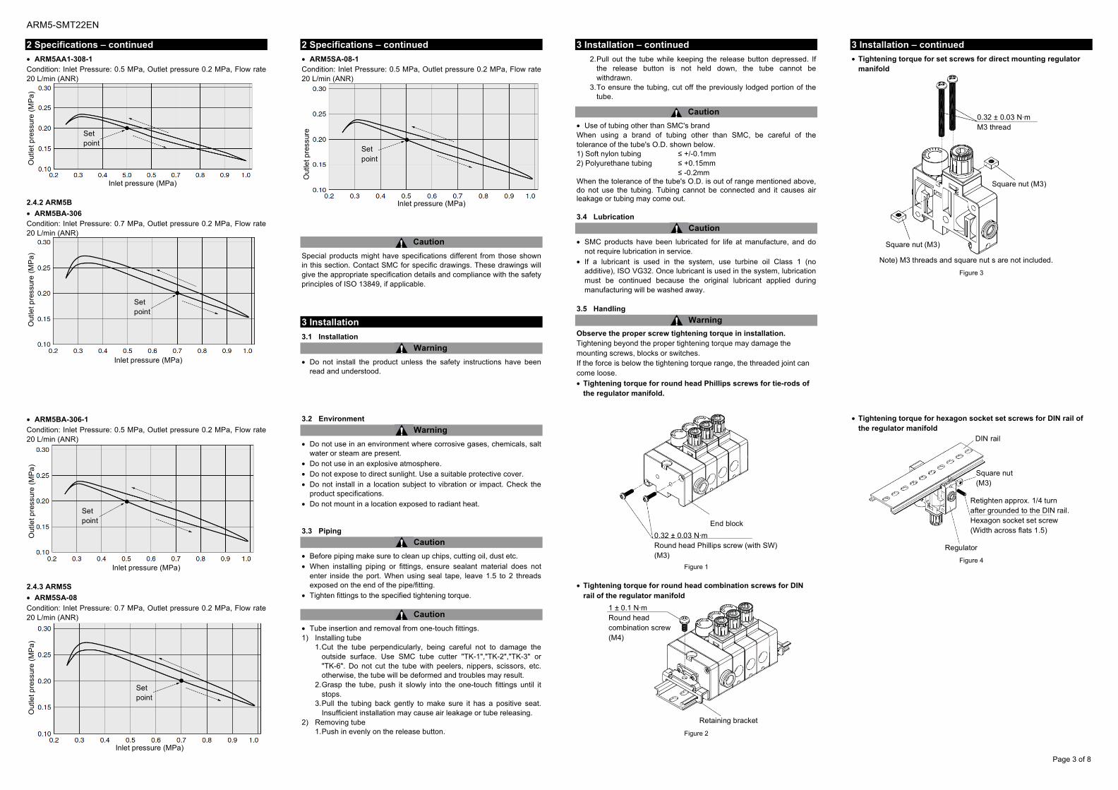
• ARM5AA1-308-1 Condition: Inlet Pressure: 0.5 MPa, Outlet pressure 0.2 MPa, Flow rate 20 L/min (ANR)
2.4.2 ARM5B
• ARM5BA-306 Condition: Inlet Pressure: 0.7 MPa, Outlet pressure 0.2 MPa, Flow rate 20 L/min (ANR)
• ARM5BA-306-1 Condition: Inlet Pressure: 0.5 MPa, Outlet pressure 0.2 MPa, Flow rate 20 L/min (ANR)
2.4.3 ARM5S
• ARM5SA-08 Condition: Inlet Pressure: 0.7 MPa, Outlet pressure 0.2 MPa, Flow rate 20 L/min (ANR)
2 Specifications – continued
• ARM5SA-08-1 Condition: Inlet Pressure: 0.5 MPa, Outlet pressure 0.2 MPa, Flow rate 20 L/min (ANR)
Caution Special products might have specifications different from those shown in this section. Contact SMC for specific drawings. These drawings will give the appropriate specification details and compliance with the safety principles of ISO 13849, if applicable.
3 Installation
3.1 Installation
Warning • Do not install the product unless the safety instructions have been
read and understood.
3.2 Environment
Warning • Do not use in an environment where corrosive gases, chemicals, salt
water or steam are present. • Do not use in an explosive atmosphere. • Do not expose to direct sunlight. Use a suitable protective cover. • Do not install in a location subject to vibration or impact. Check the
product specifications. • Do not mount in a location exposed to radiant heat. 3.3 Piping
Caution • Before piping make sure to clean up chips, cutting oil, dust etc. • When installing piping or fittings, ensure sealant material does not
enter inside the port. When using seal tape, leave 1.5 to 2 threads exposed on the end of the pipe/fitting.
• Tighten fittings to the specified tightening torque.
Caution • Tube insertion and removal from one-touch fittings. 1) Installing tube
1. Cut the tube perpendicularly, being careful not to damage the outside surface. Use SMC tube cutter "TK-1","TK-2","TK-3" or "TK-6". Do not cut the tube with peelers, nippers, scissors, etc. otherwise, the tube will be deformed and troubles may result.
2. Grasp the tube, push it slowly into the one-touch fittings until it stops.
3. Pull the tubing back gently to make sure it has a positive seat. Insufficient installation may cause air leakage or tube releasing.
2) Removing tube 1. Push in evenly on the release button.
3 Installation – continued
2. Pull out the tube while keeping the release button depressed. If the release button is not held down, the tube cannot be withdrawn.
3. To ensure the tubing, cut off the previously lodged portion of the tube.
Caution • Use of tubing other than SMC's brand When using a brand of tubing other than SMC, be careful of the tolerance of the tube's O.D. shown below. 1) Soft nylon tubing ≤ +/-0.1mm 2) Polyurethane tubing ≤ +0.15mm ≤ -0.2mm When the tolerance of the tube's O.D. is out of range mentioned above, do not use the tubing. Tubing cannot be connected and it causes air leakage or tubing may come out. 3.4 Lubrication
Caution • SMC products have been lubricated for life at manufacture, and do
not require lubrication in service. • If a lubricant is used in the system, use turbine oil Class 1 (no
additive), ISO VG32. Once lubricant is used in the system, lubrication must be continued because the original lubricant applied during manufacturing will be washed away.
3.5 Handling
Warning Observe the proper screw tightening torque in installation. Tightening beyond the proper tightening torque may damage the mounting screws, blocks or switches. If the force is below the tightening torque range, the threaded joint can come loose. • Tightening torque for round head Phillips screws for tie-rods of
the regulator manifold.
Figure 1
• Tightening torque for round head combination screws for DIN
rail of the regulator manifold
Figure 2
3 Installation – continued
• Tightening torque for set screws for direct mounting regulator manifold
Figure 3
• Tightening torque for hexagon socket set screws for DIN rail of the regulator manifold
Figure 4
Inlet pressure (MPa)
Out
let p
ress
ure
(M
Pa
)
Set point
Out
let p
ress
ure
(M
Pa
)
Inlet pressure (MPa)
Set point
Out
let p
ress
ure
(M
Pa
)
Inlet pressure (MPa)
Set point
Out
let p
ress
ure
(M
Pa
)
Inlet pressure (MPa)
Set point
Out
let p
ress
ure
(M
Pa
)
Inlet pressure (MPa)
Set point
End block
0.32 ± 0.03 N·m Round head Phillips screw (with SW) (M3)
Retaining bracket
1 ± 0.1 N·m Round head combination screw (M4)
0.32 ± 0.03 N·m M3 thread
Square nut (M3)
Square nut (M3)
Note) M3 threads and square nut s are not included.
DIN rail
Square nut (M3)
Retighten approx. 1/4 turn after grounded to the DIN rail. Hexagon socket set screw (Width across flats 1.5)
Regulator

ARM5-SMT22EN
Page 4 of 8
3 Installation – continued
3.6 How to Add Manifold (Series ARM5A/B)
3.6.1 In case of the centralized air supply type It is possible to add the centralized air supply block or regulator block and also alter the position.
Figure 5
(1) Disassembly 1. Loosen the 4 round head Phillips screws at the corners of the end
block. (Each 2 locations on both the right and left side) 2. Remove the tie-rod from the end block, centralized air supply
block, and regulator block. (2) Additional parts (Please prepare separately)
1. Centralized supply block, Regulator block 2. Tie-rod Note) A tie-rod, which is corresponding to the regulator block
stations, or additional tie-rod for increasing the station will be required.
(3) Assembly 1. Connect the tie rods. 2. Insert the tie-rod to the end block on the L side, and temporarily
tighten the round head Phillips screws (2 screws). 3. Check the O-ring is fitted in the groove of the connection on each
manifold block and then insert each block to the tie-rod. 4. Temporarily tighten the round head Phillips screws on the R side
(2 screws). 5. Additionally tighten the round head Phillips screws on both sides
of the manifold with the recommended tightening torque.
Caution • Before disassembly, be sure that no inlet or outlet pressure is applied
and exhaust the internal pressure thoroughly before starting the job. • After assembly, if the connection between each block, or the
tightened tie-rod screws are insufficient, air leakage may occur. Before use, only connect the air after confirming that all the components are securely fixed and that there is no air leakage.
3 Installation – continued
3.6.2 How to remove DIN rail for DIN rail mount type
Figure 6 (1) Disassembly
1. Loosen the round head combination screws (located on both the right and left side).
2. Remove the DIN rail, sliding it horizontally. 3. Remove the retaining bracket.
(2) Assembly 1. Set the retaining bracket to the original position. 2. Insert the DIN rail. 3. Tighten the round head combination screw with the
recommended tightening torque (located on both the right and left side).
3.6.3 In case of the Individual air supply type It is possible to add the regulator block and also alter the position.
Figure 7
(1) Disassembly 1. Loosen the 4 round head Phillips screws at the corners of the end
block. (Each 2 locations on both the right and left side) 2. Remove the tie-rod from the end block and regulator block.
(2) Additional parts (Please prepare separately) 1. Regulator block 2. Tie-rod
3 Installation – continued
Note) A tie-rod, which is corresponding to the regulator block stations, or additional tie-rod for increasing the station will be required.
(3) Assembly 1. Connect the tie-rods. 2. Insert the tie-rod to the end block on the L side, and temporarily
tighten the round head Phillips screws (2 screws). 3. Insert each block to the tie-rod. 4. Temporarily tighten the round head Phillips screws on the R side
(2 screws). 5. Additionally tighten the round head Phillips screws on both sides
of the manifold with the recommended tightening torque.
Caution • Before disassembly, be sure to check that no inlet or outlet pressure
is applied and exhaust the internal pressure thoroughly before starting the job.
3.6.4 How to remove DIN rail for DIN rail mount type
Figure 8 (1) Disassembly
1. Loosen the round head combination screws (located on both the right and left side).
2. Remove the DIN rail, sliding it horizontally. 3. Remove the retaining bracket.
(2) Assembly 1. Set the retaining bracket to the original position. 2. Insert the DIN rail. 3. Tighten the round head combination screw with the
recommended tightening torque (located on both the right and left side).
4 Settings
4.1 Adjustment
4.1.1 Regulators
Warning • Set the regulator while confirming the inlet pressure and the outlet
pressure displayed on the pressure gauge. Rotating the handle excessively may damage internal parts.
• Rotate the pressure adjustment handle only after unlocking. If rotated while locked, the connecting part between the body and the bonnet may be damaged.
• For pressure adjustment handle operation, a hexagon wrench can be used in the direction of the pressure increase. If it is used in the direction of pressure decrease, the handle may be damaged. Operate the handle manually.
Caution • Set the regulator while carefully confirming the inlet pressure.
• The outlet pressure range must be 85% or less than the inlet pressure. However, it must be within the set pressure range.
• Release the lock to adjust the pressure. After the adjustment, engage the lock. Failure to observe this procedure could damage the handle or cause the outlet pressure to fluctuate.
• Turn the pressure adjustment handle clockwise to increase the outlet pressure and counterclockwise to decrease the pressure. (To set the pressure, do so in the direction of pressure increase.)
4.1.2 Pressure gauge and One-touch fittings
Caution • Both the pressure gauge and the One-touch fittings are a cassette
type, so that it is possible to rotate them freely. Rotate them after confirming that there is no pressure inside and exhausting air completely.
L side end block
Tie-rod for centralized supply block
Tie-rod O-ring
Groove of the connection
R side end block
Groove of the connection
O-ring
Round head Phillips screw (with SW) (M3) Recommended tightening torque: 0.32 ± 0.03 N·m
Tie-rod for adding a regulator
Centralized supply block
O-ring
Regulator block for centralized supply type
Round head combination screw (M4)
Recommended tightening torque: 1 ± 0.1 N·m
DIN rail
Retaining bracket
Centralized supply type manifold
Round head Phillips screw (with SW) (M3) Recommended tightening torque: 0.32 ± 0.03 N·m
L side end block
Tie-rod
Tie-rod for adding a regulator
Regulator block for individual supply type
R side end block DIN rail
Retaining bracket
Individual supply type manifold
Round head combination screw (M4) Recommended tightening torque: 1 ± 0.1 N·m

ARM5-SMT22EN
Page 5 of 8
5 How to Order
5.1 ARM5A
5 How to Order – continued
5.2 ARM5B
ARM5 B A – 4 07 –
1 2 3 4 5 6
1. Manifold Mounting Symbol A B
How to mount Direct mount DIN rail mount
Appearance
2. Regulator Block Stations Symbol Stations
1 1 station 2 2 stations 3 3 stations 4 4 stations 5 5 stations 6 6 stations 7 7 stations 8 8 stations 9 9 stations M 10 stations
1 2 3 station stations stations ….
3. IN/OUT Piping Position Metric size Mounting position
IN side OUT side
Fitting type Straight Elbow Straight Elbow Symbol Ø4 Ø6 Ø4 Ø6 Ø4 Ø6 Ø4 Ø6
06 07 08 18 19 20 25 26 27 32 33 34
Inch size Mounting position
IN side OUT side
Fitting type Straight Elbow Straight Elbow Symbol Ø5/32 Ø1/4 Ø5/32 Ø1/4 Ø5/32 Ø1/4 Ø5/32 Ø1/4
56 57 58 68 69 70 75 76 77 82 83 84
Straight Elbow
IN side
Straight Elbow
OUT side (Back side)
4. Accessory
Symbol Pressure
gauge Note) Configuration
Nil None
A Yes
Note) Pressure gauges are not compatible with
copper-free and fluorine-free specifications.
5. Semi-standard
Symbol None 0.35 MPa setting Note)
Non-relieving
Nil 1 2 3
Note) A pressure gauge with a full span of
0.8 MPa is attached.
6. Unit Representation Symbol Description
Nil Display unit for product name
plate and pressure gauge: MPa
Z Note) Display unit for product name plate and pressure gauge: psi
Note) This option is available for use outside Japan only (The SI units must be used in Japan)
Individual supply type
ARM5 A A 1 – 4 07 – A
1 2 3 4 5 6 7
1. Manifold Mounting Symbol A B
How to mount Direct mount DIN rail mount
Appearance
2. Centralized Supply (IN) Piping Position Symbol 1 2
Piping position Bottom Top
Appearance
OUT OUT OUT OUT
IN
OUT OUT OUT OUT IN
3. Regulator Block Stations Symbol Stations
1 1 station 2 2 stations 3 3 stations 4 4 stations 5 5 stations 6 6 stations 7 7 stations 8 8 stations 9 9 stations M 10 stations
1 2 3 station stations stations ….
4. IN/OUT Fitting Type (Refer to the figure below) Metric size Mounting position
IN side OUT side
Fitting type Straight Elbow Straight Elbow Symbol Ø6 Ø8 Ø6 Ø8 Ø4 Ø6 Ø4 Ø6
07 08 09 10 19 20 21 22 26 27 28 29 33 34 35 36
Inch size Mounting position
IN side OUT side
Fitting type Straight Elbow Straight Elbow Symbol Ø1/4 Ø5/16 Ø1/4 Ø5/16 Ø5/32 Ø1/4 Ø5/32 Ø1/4
57 58 59 60 69 70 71 72 76 77 78 79 83 84 85 86
Straight Elbow
IN side
Straight Elbow
OUT side (Back side)
5. Accessories
Symbol
Pressure gauge Note) Centralized supply block mounting position
Yes None L side R side B side (Left) (Right) (Both)
Centralized supply block
Centralized supply block
Centralized supply block
A B C D E F
Note) Pressure gauges are not compatible with copper-free and fluorine-free specifications.
6. Semi-standard
Symbol None 0.35 MPa setting Note)
Non-relieving
Nil 1 2 3
Note) A pressure gauge with a full span of
0.8 MPa is attached.
7. Unit Representation Symbol Description
Nil Display unit for product
name plate and pressure gauge: MPa
Z Note) Display unit for product
name plate and pressure gauge: psi
Note) This option is available for use outside Japan only (The SI units must be used in Japan)
Centralized supply type
ARM5-SMT22EN
Page 6 of 8
5 How to Order – continued
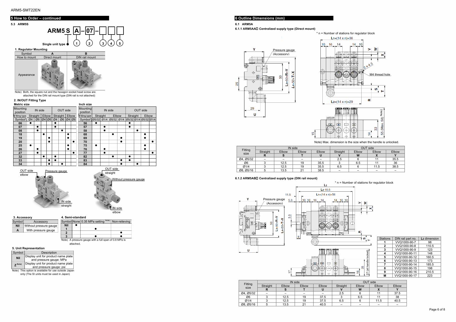
5.3 ARM5S
6 Outline Dimensions (mm)
6.1 ARM5A
6.1.1 ARM5AA Centralized supply type (Direct mount)
6.1.2 ARM5AB Centralized supply type (DIN rail mount)
ARM5 S A – 07 –
1 2 3 4 5
1. Regulator Mounting Symbol A B
How to mount Direct mount DIN rail mount
Appearance
Note) Both, the square nut and the hexagon socket head screw are
attached for the DIN rail mount type (DIN rail is not attached)
2. IN/OUT Fitting Type Metric size Mounting position
IN side OUT side
Fitting type Straight Elbow Straight Elbow Symbol Ø4 Ø6 Ø4 Ø6 Ø4 Ø6 Ø4 Ø6
06 07 08 18 19 20 25 26 27 32 33 34
Inch size Mounting position
IN side OUT side
Fitting type Straight Elbow Straight Elbow Symbol Ø5/32 Ø1/4 Ø5/32 Ø1/4 Ø5/32 Ø1/4 Ø5/32 Ø1/4
56 57 58 68 69 70 75 76 77 82 83 84
3. Accessory Symbol Accessory
Nil Without pressure gauge
A With pressure gauge
4. Semi-standard Symbol None 0.35 MPa setting Note) Non-relieving
Nil 1 2 3
Note) A pressure gauge with a full span of 0.8 MPa is
attached.
5. Unit Representation
Symbol Description
Nil Display unit for product name plate
and pressure gauge: MPa
Z Note) Display unit for product name plate and pressure gauge: psi
Note) This option is available for use outside Japan only (The SI units must be used in Japan)
Single unit type
OUT side elbow
Pressure gauge
IN side straight
OUT side straight
Without pressure gauge
IN side elbow
Fitting size
IN side OUT side Straight Elbow Elbow Elbow Straight Elbow Elbow Elbow
R S T U V W X Y Ø4, Ø5/32 – – – – 2.5 6 11 35.5
Ø6 3 12.5 19 35.5 3 6.5 11 36 Ø1/4 3 12.5 19 35.5 6.5 6 11.5 38.5
Ø8, Ø5/16 5 13.5 21 38.5 – – – –
Pressure gauge (Accessory)
* n = Number of stations for regulator block
M4 thread hole
Not
e)
Note) Max. dimension is the size when the handle is unlocked.
Fitting size
IN side OUT side Straight Elbow Elbow Elbow Straight Elbow Elbow Elbow
R S T U V W X Y Ø4, Ø5/32 – – – – 2.5 6 11 37.5
Ø6 3 12.5 19 37.5 3 6.5 11 38 Ø1/4 3 12.5 19 37.5 6.5 6 11.5 40.5
Ø8, Ø5/16 5 13.5 21 40.5 – – – –
* n = Number of stations for regulator block
Pressure gauge (Accessory)
(at h
and
le lo
cked
)
Stations DIN rail part no. L2 dimension 1 VVQ1000-90-7 98 2 VVQ1000-90-8 110.5 3 VVQ1000-90-9 123 4 VVQ1000-90-11 148 5 VVQ1000-90-12 160.5 6 VVQ1000-90-13 173 7 VVQ1000-90-14 185.5 8 VVQ1000-90-15 198 9 VVQ1000-90-16 210.5 M VVQ1000-90-17 223

ARM5-SMT22EN
Page 7 of 8
6 Outline Dimensions (mm) – continued
6.2 ARM5B
6.2.1 ARM5BA Individual supply type (Direct mount)
6.2.2 ARM5BB Individual supply type (DIN rail mount)
6 Outline Dimensions (mm) – continued
6.3 ARM5S
6.3.1 ARM5SA Single unit type (Direct mount)
6.3.2 ARM5SB Single unit type (DIN rail mount)
Fitting size
IN side OUT side Straight Elbow Elbow Elbow Straight Elbow Elbow Elbow
R S T U V W X Y Ø4, Ø5/32 2.5 6 11 35.5 2.5 6 11 35.5
Ø6 3 6.5 11 36 3 6.5 11 36 Ø1/4 6.5 6 11.5 38.5 6.5 6 11.5 38.5
Pressure gauge (Accessory)
M4 thread hole
Not
e)
Note) Max. dimension is the size when the handle is unlocked.
* n = Number of regulator block stations
Fitting size
IN side OUT side Straight Elbow Elbow Elbow Straight Elbow Elbow Elbow
R S T U V W X Y Ø4, Ø5/32 2.5 6 11 37.5 2.5 6 11 37.5
Ø6 3 6.5 11 38 3 6.5 11 38 Ø1/4 6.5 6 11.5 40.5 6.5 6 11.5 40.5
* n = Number of regulator block stations
Pressure gauge (Accessory)
57 (
at h
and
le lo
cked
)
Stations DIN rail part no. L2 dimension 1 VVQ1000-90-6 85.5 2 VVQ1000-90-7 98 3 VVQ1000-90-8 110.5 4 VVQ1000-90-9 123 5 VVQ1000-90-10 135.5 6 VVQ1000-90-12 160.5 7 VVQ1000-90-13 173 8 VVQ1000-90-14 185.5 9 VVQ1000-90-15 198 M VVQ1000-90-16 210.5
Panel cut dimension
(with
pres
sure
gaug
e)
M3 thread hole
Pressure gauge (Accessory)
55 (
at h
and
le lo
cked
)
55
(at h
and
le lo
cke
d)
Pressure gauge (Accessory)
Fitting size IN side
Straight Elbow Elbow Elbow R S T U
Ø4, Ø5/32 2.5 6 11 35.5 Ø6 3 6.5 11 36
Ø1/4 6.5 6 11.5 38.5
Fitting size OUT side
Straight Elbow Elbow Elbow V W X Y
Ø4, Ø5/32 2.5 6 11 35.5 Ø6 3 6.5 11 36
Ø1/4 6.5 6 11.5 38.5
Fitting size IN side
Straight Elbow Elbow Elbow R S T U
Ø4, Ø5/32 2.5 6 11 37.5 Ø6 3 6.5 11 38
Ø1/4 6.5 6 11.5 40.5
Fitting size OUT side
Straight Elbow Elbow Elbow V W X Y
Ø4, Ø5/32 2.5 6 11 37.5 Ø6 3 6.5 11 38
Ø1/4 6.5 6 11.5 40.5
ARM5-SMT22EN
Page 8 of 8
7 Maintenance
7.1 General Maintenance
Caution • Not following proper maintenance procedures could cause the
product to malfunction and lead to equipment damage. • If handled improperly, compressed air can be dangerous.
Maintenance of pneumatic systems should be performed only by qualified personnel.
• Before performing maintenance, turn off the power supply and be sure to cut off the supply pressure. Confirm that the air is released to atmosphere.
• After installation and maintenance, apply operating pressure and power to the equipment and perform appropriate functional and leakage tests to make sure the equipment is installed correctly.
• If any electrical connections are disturbed during maintenance, ensure they are reconnected correctly and safety checks are carried out as required to ensure continued compliance with applicable national regulations.
• Do not make any modification to the product. • Do not disassemble the product, unless required by installation or
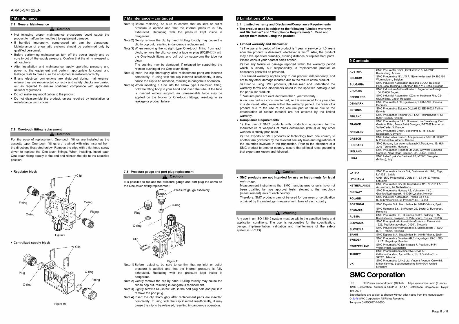
maintenance instructions. 7.2 One-touch fitting replacement
Caution For the ease of replacement, One-touch fittings are installed as the cassette type. One-touch fittings are retained with clips inserted from the directions illustrated below. Remove the clips with a flat head screw driver to replace the One-touch fittings. When installing, insert each One-touch fitting deeply to the end and reinsert the clip to the specified position.
• Regulator block
Figure 9
• Centralized supply block
Figure 10
7 Maintenance – continued
Note 1) Before replacing, be sure to confirm that no inlet or outlet pressure is applied and that the internal pressure is fully exhausted. Replacing with the pressure kept inside is dangerous.
Note 2) Gently remove the clip by hand. Pulling forcibly may cause the clip to pop out, resulting in dangerous replacement.
Note 3) When removing the straight type One-touch fitting from each block, remove the clip, connect a tube or plug (KQ2P-) with the One-touch fitting, and pull out by supporting the tube (or plug). The bushing may be damaged, if released by supporting the release bushing of the One-touch fitting.
Note 4) insert the clip thoroughly after replacement parts are inserted completely. If using with the clip inserted insufficiently, it may cause the clip to be released, resulting in dangerous operation.
Note 5) When inserting a tube into the elbow type One-touch fitting, hold the fitting body in your hand and insert the tube. If the tube is inserted without support, an unreasonable force may be applied on the blocks or One-touch fittings, resulting in air leakage or product failure.
7.3 Pressure gauge and port plug replacement
Caution It is possible to replace the pressure gauge and port plug the same as the One-touch fitting replacement.
Figure 11
Note 1) Before replacing, be sure to confirm that no inlet or outlet pressure is applied and that the internal pressure is fully exhausted. Replacing with the pressure kept inside is dangerous.
Note 2) Gently remove the clip by hand. Pulling forcibly may cause the clip to pop out, resulting in dangerous replacement.
Note 3) Lightly screw a M3 screw, etc. in the port plug hole and pull it to remove the port plug.
Note 4) Insert the clip thoroughly after replacement parts are inserted completely. If using with the clip inserted insufficiently, it may cause the clip to be released, resulting in dangerous operation.
8 Limitations of Use
8.1 Limited warranty and Disclaimer/Compliance Requirements
• The product used is subject to the following “Limited warranty and Disclaimer” and “Compliance Requirements”. Read and accept them before using the product.
• Limited warranty and Disclaimer 1) The warranty period of the product is 1 year in service or 1.5 years after the product is delivered, whichever is first(1). Also, the product may have specified durability, running distance or replacement parts. Please consult your nearest sales branch. 2) For any failure or damage reported within the warranty period which is clearly our responsibility, a replacement product or necessary parts will be provided. This limited warranty applies only to our product independently, and not to any other damage incurred due to the failure of the product. 3) Prior to using SMC products, please read and understand the warranty terms and disclaimers noted in the specified catalogue for the particular products. (1) Vacuum pads are excluded from this 1 year warranty. A vacuum pad is a consumable part, so it is warranted for a year after it is delivered. Also, even within the warranty period, the wear of a product due to the use of the vacuum pad or failure due to the deterioration of rubber material are not covered by the limited warranty.
• Compliance Requirements 1) The use of SMC products with production equipment for the manufacture of weapons of mass destruction (WMD) or any other weapon is strictly prohibited. 2) The exports of SMC products or technology from one country to another are governed by the relevant security laws and regulations of the countries involved in the transaction. Prior to the shipment of a SMC product to another country, assure that all local rules governing that export are known and followed.
Caution • SMC products are not intended for use as instruments for legal
metrology. Measurement instruments that SMC manufactures or sells have not been qualified by type approval tests relevant to the metrology (measurement) laws of each country. Therefore, SMC products cannot be used for business or certification ordained by the metrology (measurement) laws of each country.
Warning Any use in an ISO 13849 system must be within the specified limits and application conditions. The user is responsible for the specification, design, implementation, validation and maintenance of the safety system (SRP/CS)
9 Contacts
AUSTRIA SMC Pneumatik GmbH,Girakstrasse 8, AT-2100 Korneuburg, Austria
BELGIUM SMC Pneumatics N.V. ⁄ S.A. Nijverheidsstraat 20, B-2160 Wommelgem, Belgium
BULGARIA SMC Industrial Automation Bulgaria EOOD, Business Park Sofia, Building 8-6th floor, BG-1715 Sofia, Bulgaria
CROATIA SMC IndustrijskaAutomatikad.o.o. Zagreba�kaAvenija 104,10 000 Zagreb
CZECH REP. SMC Industrial Automation CZ s.r.o. Hudcova 78a, CZ-61200 Brno, Czech Republic
DENMARK SMC Pneumatik A ⁄ S,Egeskovvej 1, DK-8700 Horsens, Denmark
ESTONIA SMC Pneumatics Estonia Oü,Laki 12, EE-10621 Tallinn, Estonia
FINLAND SMC Pneumatics Finland Oy, PL72, Tiistinniityntie 4, SF-02031 Espoo, Finland
FRANCE SMC Pneumatique SA.1, Boulevard de Strasbourg, Parc Gustave Eiffel, Bussy Saint Georges, F-77607 Marne La ValleeCedex 3, France
GERMANY SMC Pneumatik GmbH, Boschring 13-15, 63329 Egelsbach, Germany
GREECE SMC Italia Hellas Branch, Anagenniseos 7-9-P.C. 14342 N.Philadelphia, Athens, Greece
HUNGARY SMC Hungary IpariAutomatizálásiKft.Torbágy u. 19, HU-2045 Törökbálint, Hungary
IRELAND SMC Pneumatics (Ireland) Ltd.2002 Citywest Business Campus, Naas Road, Saggart, Co. Dublin, Ireland
ITALY SMC Italia S.p.A.Via Garibaldi 62, I-20061Carugate, (Milano), Italy
LATVIA SMC Pneumatics Latvia SIA, Dzelzavas str. 120g, Riga, LV-1021, Latvia
LITHUANIA UAB “SMC Pneumatics”, Oslo g. 1, LT-04123 Vilnius, Lithuania
NETHERLANDS SMC Pneumatics B.V.De Ruyterkade 120, NL-1011 AB Amsterdam, the Netherlands
NORWAY SMC Pneumatics Norway AS, Vollsveien 13 C, GranfosNæringspark, N-1366 Lysaker, Norway
POLAND SMC Industrial Automation, Polska Sp z o.o. 02-826 Warszawa, ul. Poloneza 89, Poland
PORTUGAL SMC España S.A. Zuazobidea 14, 01015 Vitoria, Spain
ROMANIA SMC Romania S.r.l. StrFrunzei 29, Sector 2, Bucharest, Romania
RUSSIA SMC Pneumatik LLC. Business centre, building 3, 15 Kondratjevskij prospect, St.Petersburg, Russia, 195197
SLOVAKIA SMC PriemyselnáAutomatizáciaSpols.r.o. Fantranská 1223, Teplickanadvahom, 01301, Slovakia
SLOVENIA SMC IndustrijskaAvtomatikad.o.o. Mirnskacesta 7, SLO-8210 Trebnje, Slovenia
SPAIN SMC España S.A. Zuazobidea 14, 01015 Vitoria, Spain
SWEDEN SMC Pneumatics Sweden AB,Ekhagsvägen 29-31, SE-141 71 Segeltorp, Sweden
SWITZERLAND SMC Pneumatik AG,Dorfstrasse 7, Postfach, 8484 Weisslingen, Switzerland
TURKEY SMC PnömatikSanayiTicaretveServis A.�. GülbaharCaddesi, Aydın Plaza, No: 9 ⁄ 4 Güne�li – 34212 , Istanbul
UK SMC Pneumatics (U.K.) Ltd. Vincent Avenue, Crownhill, Milton Keynes, Buckinghamshire MK8 0AN, United Kingdom
URL : http// www.smcworld.com (Global) http// www.smceu.com (Europe)
'SMC Corporation, Akihabara UDX15F, 4-14-1, Sotokanda, Chiyoda-ku, Tokyo
101 0021
Specifications are subject to change without prior notice from the manufacturer.
© 2016 SMC Corporation All Rights Reserved.
Template DKP50047-F-085D
Fitting
Fitting O-ring
O-ring
Clip
Clip
Fitting
O-ring
O-ring
Plug
O-ring
O-ring
Clip
Plug
Pressure gauge assembly