INSTRUCTION MANUAL - Spares Direct 2 Usparesdirect2u.com/downloads/FSA Oil Fuse Switch -...
50
INSTRUCTION MANUAL FOR THE RANGE OF METALCLAD AUTOMATIC O I L FUSE SWITCHES EQU IPMENT RATED VOLTAGE UP TO 15.5kV The successful operation of all switchgear depends largely upon careful erection, systematic inspection at regular intervals and the maintenance of all parts in a satisfactory condition. If the equipment described in this manual receives the recommended attention it will give many years of reliable and trouble-free service. Since all designs in the Yorkshire Switchgear range are the subject of continuous research and development work the equipment supplied may differ in minor details from that described. However, we will be happy to supply on request any additional information which may be required. Please quote the serial number(s) of the unit(s) concerned, the date and reference number of this manual, the part number where applicable, and the contract number if known, with any enquiry. YORKSHIRE SWITCHGEAR LTD. Meanwood, Leeds. LS6 28N, England. AUGUST, 1981. Ref: D49-P1 - 39 July, 1982. Ref: D9A-PI-5/YEB TELEPHONE - National: 0532 757121. International: +44 532 757121. TELEX - 557564 YORKSS G. CABLES - CONTROLLER LEEDS.
Transcript of INSTRUCTION MANUAL - Spares Direct 2 Usparesdirect2u.com/downloads/FSA Oil Fuse Switch -...
INSTRUCTION MANUAL
FOR
THE
RANGE OF METALCLAD
AUTOMATIC
OIL FUSE SWITCHES
EQU IPMENT RATED VOLTAGE UP TO 15.5kV
The s u c c e s s f u l o p e r a t i o n of a l l s w i t c h g e a r depends l a r g e l y upon c a r e f u l e r e c t i o n , s y s t e m a t i c i n s p e c t i o n a t r e g u l a r i n t e r v a l s and t h e ma in tenance of a l l p a r t s i n a s a t i s f a c t o r y c o n d i t i o n . I f t h e equipment d e s c r i b e d i n t h i s manual r e c e i v e s t h e recommended a t t e n t i o n i t w i l l g i v e many y e a r s of r e l i a b l e and t r o u b l e - f r e e s e r v i c e .
S i n c e a l l d e s i g n s i n t h e Y o r k s h i r e S w i t c h g e a r r ange a r e t h e s u b j e c t of c o n t i n u o u s r e s e a r c h and deve lopmen t work t h e equipment s u p p l i e d may d i f f e r i n minor d e t a i l s from t h a t d e s c r i b e d . However, we w i l l be happy t o s u p p l y on r e q u e s t any a d d i t i o n a l i n f o r m a t i o n which may be r e q u i r e d . P l e a s e q u o t e t h e s e r i a l number(s) o f t h e u n i t ( s ) c o n c e r n e d , t h e d a t e and r e f e r e n c e number of t h i s manual , t h e p a r t number where a p p l i c a b l e , and t h e c o n t r a c t number i f known, w i t h any e n q u i r y .
YORKSHIRE SWITCHGEAR LTD. Meanwood, Leeds. LS6 28N, England.
AUGUST, 1981. Ref: D49-P1 - 39 J u l y , 1982. Ref: D9A-PI-5/YEB
TELEPHONE - N a t i o n a l : 0532 757121. I n t e r n a t i o n a l : +44 532 757121. TELEX - 557564 YORKSS G . CABLES - CONTROLLER LEEDS.

CONTENTS
THE "FS-A" RANGE OF FUSE SWITCHES - GENERAL DESCRIPTION Basic Design Concept Main Switch Fuses p
Transformer Earth Switch Circuit Connections Busbars Interlocks and Padlocking Technical Specification
2 DETAILED DESCRIPTION OF MAIN SWITCH 2.1 Principal Features 2.2 Operating Sequence
3 DETAILED DESCRIPTION OF TRANSFORMER EARTH SWITCH 3.1 Principal Features 3.2 Operating Sequence
DELIVERY & ERECTION: FS-A Loading, Delivery and Unloading Delivery Weight, Oil and Compound Volumes Storage of Switchgear Preparation of Switchroom Floor (for Unistrut Foundations) Erection of Fixed Portions and other units on Unistrut Fitting the Busbars Jointing of Cables
5 DELIVERY 6 ERECTION: FS-A0 5.1 Loading, Delivery, Unloading and Storage 5.2 Delivery Weight, Oil and Compound Quantities 5.3 Erection: Smooth Concrete Floor 5.4 Erection: Unistrut Foundations 5.5 Jointing the Busbars 5.6 Jointing of Cables
6 DELIVERY & ERECTION: FS-AT 6.1 Loading, Delivery, Unloading and Storage 6.2 Delivery Weight. Oil and Compound Volumes 6.3 Mounting the Fuse Switch on the Transformer 6.4 Erection of Free-Standing Fuse Switch with Rear Cable Box . 6.5 Jointing of Cables
7 PREPARATION & COMMISSIONING 7.1 Preparation of Tank and Mechanisms 7.2 Oil Filling of Switchgear 7.3 High Voltage Tests 7.4 Paintwork
8 ROUTINE FUSE SWITCH OPERATION 8.1 To Close the Main Fuse Switch to ON 8.2 To Trip the Main Fuse Switch to OFF 8.3 Fuse Operation on Fault 8.4 To Earth the Transformer Circuit 8.5 To Remove the Earth frcm the Transformer Circuit
MAINTENANCE Frequency of Maintenance Maintenance of Tank & Mechanisms Switch Oil Sampling and Testing Post Fault Maintenance and Fuse Renewal Changing from 254 mm (10 in) to 359 mm (14.1/8 in) Fuses Changing from 359 mm (14.118 in) to 254 mm (10 in) Fuses Maintenance of Busbar Chamber
10 SPARES 6 TOOLS 10.1 Spare Parts 10.2 Tools
1. THE PS-A" RANGE OF RISE SWITCHES - GENERAL DESCRIPTION
1.1 B a s i c Design Concept
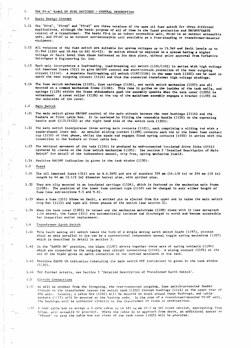
1.11 The "FS-A", "FS-AO" and 35-AT" a r e t h r e e v e r s i o n s of t h e same o i l f u s e s v i t c h f o r t h r e e d i f f e r e n t a p p l i c a t i o n s , a l t h o u g h t h e b a s i c purpose of a l l of them is t h e fused p r o t e c t i o n and ON/OPF/EARlW c o n t r o l of a t r a n s f o r m e r . The b a s i c FS-A is a n indoor e x t e n s i b l e u n i t , FS-A0 i s a n outdoor e x t e n s i b l e u n i t , and FS-AT is a n o u t d o o r non-ex tens ib le u n i t a v a i l a b l e a s a f r e e s t a n d i n g o r t r a n s f o w e r m o u n t e d equipment.
A l l v e r s i o [ p s of t h e f u s e w i t c h are s u i t a b l e f o r system v o l t a g e s up t o 15.5kV and f a u l t l e v e l s up t o 21 .9M (12kV and 18.4kA t o ESI 41-12). No s v i t c h should b e employed on a sys tem having a h i g h e r v o l t a g e o r f a u l t l e v e l t h a n t h o s e i n d i a a t e d on i t s d a t a p l a t e , without p r i o r a p p r o v a l from Y o r k s h i r e Swi tchgear 6 E n g i n e e r i n g Co. Ltd.
Each u n i t i n c o r p o r a t e s a load-making, load-breaking o i l s w i t c h (1101/1102) i n series v l t h h i g h v o l t a g e o i l immersed f u s e s (311) t o g i v e ON/OFF c o n t r o l and s h o r t - c i r c u i t p r o t e c t i o n of t h e r e a r o u t g o i n g c i r c u i t (1114)- A s e p a r a t e f a u l t - m a k i n g o i l s v i t c h (1197/1104) i n t h e same t a n k (1202) c a n be used t o e a r t h t h e rear o u t g o i n g c i r c u i t (1114) and t h u s the connected t ransformer h i g h v o l t a g e windings.
The f u s e s w i t c h mechanism (11051, f u s e c a r r i a g e (1106), and e a r t h s w i t c h nechanism (1107) a r e all mounted on a common mechanism frame (1108). T h i s runs i n g u i d e s on t he i n s i d e s of t h e t a n k w a l l s , and s p r i n g s (1129) w i t h i n t h e frame sidemembers push t h e assembly upvards vhen t h e t a n k c o v e r (1205) is unfas tened . A c o v e r r o l l e r (1128) a t t h e t o p of t he mainframe assembly engages a b r a c k e t (1159) o n t h e u n d e r s i d e of t h e cover .
Main Swi tch
The main s w i t c h g i v e s ON/OFF c o n t r o l o f t h e main c i r c u i t between t h e r e a r b u s h i n g s (1114) and t h e b u s b a r s o r f r o n t c a b l e box. It is o p e r a t e d by f i t t i n g t h e removable h a n d l e (1126) t o t h e o p e r a t i n g handle s t u b (1121/1122) a t t h e r i g h t hand s i d e of t h e s v i t c h tank (1202).
The main s w i t c h i n c o r p o r a t e s t h r e e moving main c o n t a c t s (1101). each compr is ing a s l i d i n g rod v i t h a spade-shaped l o v e r end. An a n n u l a r s l i d i n g c o n t a c t (1109) connec ts each rod t o t h e l o v e r f u s e c o n t a c t cup (1110) of t h a t phase , w h i l s t t h e spade end engages f i x e d s p r i n g c o n t a c t s (1102) i n s e r i e s v i t h t h e c o n n e c t i o n t o t h e b u s b a r s o r f r o n t c a b l e box.
The v e r t i c a l [[p[[#p#pi[p t h e r o d s (1101) is produced by end-connected i n s u l a t e d d r i v e l i n k s (1111) o p e r a t e d by c r a n k s on t h e f u s e s w i t c h mechanism (1105). See s e c t i o n 2 " D e t a i l e d D e s c r i p t i o n of Main S v i t c h " f o r d e t a i l of t h e independent manual, t r i p f r e e , s p r i n g mechanism i t s e l f .
P o s i t i v e ON/OFF i n d i c a t i o n is g i v e n i n t h e t a n k windov (1130).
Fuses - The o i l immersed f u s e s (311) a r e ~JJ B.S.2692 and a r e of s tandard 359 mm (14.1/8 i n ) o r 254 mm (10 i n ) l e n g t h by 64 ann (2.1/2 i n ) d i a m e t e r b a r r e l s i z e , w i t h s t r i k e r p ins .
They a r e c l i p mounted i n a n i n s u l a t e d c a r r i a g e (1106). v h i c h is f a s t e n e d on t h e mechanism main frame (1108). The p o s i t i o n of t h e lower f u s e c o n t a c t c u p s (1110) can be changed t o s u i t e i t h e r l e n g t h o f f u s e ( s e e sub-sec t ions 9.5 and 9 .6) .
When a f u s e (311) blows on f a u l t , a s t r i k e r p i n is e j e c t e d from i t s upper end t o r a i s e t h e main s w i t c h t r i p b a r (1112) and open a l l t h r e e phases of t h e s w i t c h ( s e e s e c t i o n 2) .
When t h e tank c o v e r (1205) i s r a i s e d and t h e mechanism mainframe (1108) r i s e s w i t h it ( s e e paragraph 1.14 above) , t h e f u s e s (311) a r e a u t o m a t i c a l l y i s o l a t e d and d ischarged t o e a r t h and become a c c e s s i b l e f o r i n s p e c t i o n a n d / o r rep lacement .
Transformer E a r t h Swi tch
This f a u l t making o i l s v i t c h t a k e s t h e form of a s i n g l e moving e a r t h swi tch b l a d e (1197) , p ivo ted about an a x i s p a r a l l e l t o i t s ovn by a c o n v e n t i o n a l independent manual t o g g l e s p r i n g mechanism (1107) which is d e s c r i b e d i n d e t a i l i n s e c t i o n 3.
I n t h e "EARTH ON" p o s i t i o n , t h e b l a d e (1197) s h o r t s t o g e t h e r t h r e e s e t s of s p r i n g c o n t a c t s (1104) which a r e connec ted t o t h e o u t g o i n g r e a r c i r c u i t c o n n e c t i o n s (1114). A wiping c o n t a c t (1195) a t t h e end of t h e b l a d e g i v e s a n e a r t h c o n n e c t i o n t o t h e ear thed metalwork of t h e tank.
P o s i t i v e EARTH ON i n d i c a t i o n ( o b s c u r i n g t h e main s w i t c h OFF i n d i c a t i o n ) is g i v e n i n t h e tank window (1130) .
For f u r t h e r d e t a i l s , s e e S e c t i o n 3 " D e t a i l e d D e s c r i p t i o n of Transformer E a r t h Switch".
C i r c u i t Connec t ions
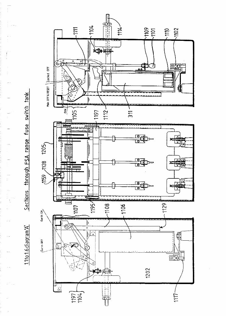
A s w i l l be e v i d e n t from t h e f o r e g o i n g , t h e rear-connected outgoing , f u s e s w i t c h - p r o ~ e c t e d f e e d e r c i r c u i t t o t h e t r a n s f o r m e r l e a v e s t h e s w i t c h t a n k (1202) through bushings (1114) a t t h e upper r e a r o f t h e u n i t . U s u a l l y , a c a b l e box (1166) w i l l be mounted on scuds around these bush ings , and c a b l e s o c k e t s (1177) w i l l be mounted a t t h e bushing ends. In t h e case of a t ransforaer-mounted FS-AT u n i t , t h e bush ings w i l l be connec ted d i r e c t l y t o the t ransformer HV l i n k s o r t e r m i n a t i o n s .
A r e a r c a b l e box t o a c c e p t a 3 c o r e c a b l e up t o 185 sq m (0 .3 sq i n ) c r o s s s e c t i o n , approaching from below, w i l l normally be provided . Where t h e c a b l e is to approach from above, a n a d d i t i o n a l s p a c e r or " t h r o a t " t o s t e p t h e c a b l e box o u t c l e a r of t h e tank cover (1205) w i l l be provided.

L I D H I N G E D FOR
MECHANISM R E M O V A L M o ~ t &F&C. EI(~TU,.,L I
L I D HINGED FOR /'
FUSE ACCESS
I
1.1 to 1.6diagram'BJ: FSA Indoor Extensible Oi l Fuse Switch
I, 0
1'
A I R INSULATED BUSBAR
C8aculT E ~ a w OFF POSITIOU
1125/1126 M~tuarcwcu O u P ~ w r t o ~
L l n U ~ U O E O BACK Foe 1121/126
F 1 1 5 ~ A C C L S ~ 1120
. 13 to1.6 diagram '[' : FSAO Outdoor Extensible Oil Fuse Switch
1.1 to 1.6 diag
13 t o 1.6 diagrambD' : FSAT Freestanding Oil Fuse Switch
An FS-AT u n i t w i l l have, i n add i t ion , a l o r l e v e l f ron t cable box of s i m i l a r design.
Cable boxes designed t o be compound f i l l e d once the cable i s i n s t a l l e d a r e provided a s s tandard. However, o t h e r methods of i n s u l a t i o n and cab le terminat ion can be catered f o r i n spec ia l circumstances.
Busbars
The indoor ex tens ib l e FS-A and outdoor ex tens ib l e FS-A0 employ d i f f e r e n t busbar systems.
The busbar chamber (319) and f i t t i n g s of t he indoor PS-A a r e f u l l y compatible with those of t h e complementary indoor c i r c u i t breaker and , o i l swi tch t o permit t he cons t ruc t ion of c m p o s i t e indoor switchboards. The panel width of a l l s tandard u n i t s is the same, and only a b r i e f busbar outage is necessary to permit the replacement of one type of u n i t by another. The r e s i n moulding (318) which suppor ts the r ec t angu la r s ec t ion busbars and incorpora t e s the tee-off connections passes f r m t h e busbar chamber (319), through i n t o the o i l tank (1202) , where the three conductors a r e connected to the main switch love r fuse c o n t a c t s (1110) v i a c o n t a c t s (1117) and (1102).
The busbar chamber (1368) and f i t t i n g s of the outdoor ex tens ib l e FS-A0 a r e f u l l y compatible with those of the complementary outdoor ex tens fb le o i l s v i t c h and r i n g a a i n u n i t , t o permit the cons t ruc t ion of composite outdoor 4svsoitchboards. A s i n g l e r e s i n moulding (1371) inco rpora t e s the c i r c u l a r s ec t ion busbars (1369) and t h e i r tee-off connections t o t h e lower fuse c o n t a c t s (1110) v i a c o n t a c t s (1117) and (1102) i n the o i l tank (1202). The unit-to-unit busbar coonections a r e insula ted by heat-shrinkable s l eeves (1370) dur ing e rec t ion .
In t e r locks & Padlocking
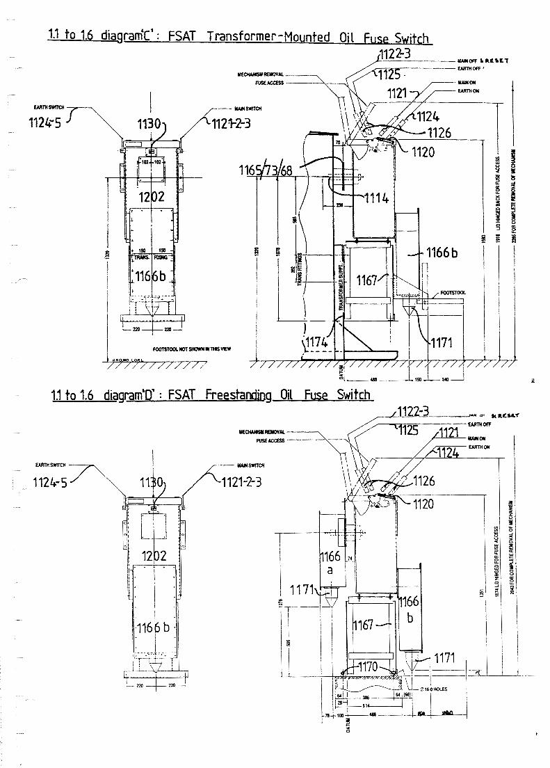
At the l e f t hand s i d e of the fuse s v i t c h mechanisms assembly (1105 & 1107) i s a pivoted i n t e r l o c k l eve r assembly (1158). This comprises a "head* (1158a) and a "tail" (1158b), secured t o opposi te ends of a spindle . When the main switch is operated t o ON, the main switch main s h a f t (1133) r o t a t e s , a s does the a t tached i n t e r l o c k cam (1190). The cam (1190) pushes the i n t e r l o c k lever " t a i l " (1158b) aga ins t the pressure of a r e tu rn sp r ing , so t h a t the i n t e r l o c k l eve r "head" (1158a) is l o w r e d to prevent the movement of the e a r t h switch d r i v e crank (1189). Thus, when the main switch is ON, t h e e a r t h switch cannot be operated to EARTH ON.
I n add i t ion , a s the main s v i t c h main l e v e r s (1198) m v e t o the ho r i zon ta l ON pos i t ion , a p in (1212) on t h e l e f t hand one engages the i n t e r l o c k l e v e r " t a i l " (1158b) to hold it i n the pos i t ion to which t h e cam has moved it ( s e e above). Thus, bo th t h e main switch mechanism main s h a f t (1133) and the main switch main l e v e r s (1198) must r e t u r n t o t h e OFF pos i t ion before the r e t u r n spr ing can pivot t h e i n t e r l o c k l eve r (1158) c l e a r of t he e a r t h swi tch d r i v e crank (1189) t o permit opera t ion to EARTH ON.
(1129 inside) ,Io8 .I 1

A t the r i g h t hand s i d e of the fu se switch mechanisms assembly (1105 6 1107) a r e the main switch d r i v e crank (1207) and an i n t e r l o c k arm(1193) mounted on the e a r t h s v i t c h b lade s i d e arm (1157). When t h e e a r t h switch i s - opera ted t o EARTH ON, t h e i n t e r l o c k arm (1193) moves so a s t o prevent r o t a t i o n of t he main swi tch d r i v e c r ank (1207). so t h a t t he main switch cannot be opera ted t o ON.
The tank cover (1205) (which can be padlocked c losed) cannot be r a i s e d , w e n i f unlocked and unfas tened, when e i t h e r swi tch is OM. The cover r o l l e r (1128) engages a b racke t (1159) on t h e cover , so t h a t t he mechanism main frame assembly (1108) holds down the cover (1205). w h i l s t t he main frame assembly i s i n t u rn held down a s fo l lows:
( a ) When the main swi tch is ON, a hole i n the ONIOFF i n d i c a t o r p l a t e (1210) on the c e n t r a l main swi tch main l e v e r (1198) engages a p p (1211) on the f ron t wa l l of t he t ank (1202);
(b ) when the e a r t h s v i t c h is s e t t o EARTH ON, the i n t e r l o c k a m (1193) on the e a r t h s u i t c h b lade s i d e arm (1157) engages a p in (1209) on the s i d e wal l of t he tank (1202).
When the cover (1205) i s r a i s e d , t he cover r o l l e r and bracket (1128, 1159) p u l l up the wchanism mainframe assembly (1108). a s s i s t e d by s p r i n g s (1129) i n t he mainframe sidemembers. Should the s v i t c h have been t r l pped by a fu se ope ra t ion , so t h a t t h e mechanism has not been r e s e t , a p in (1206) welded t o t he tank wa l l (1202) w i l l r o t a t e t he main s v i t c h d r i v e crank (1207) t o r e s e t t h e mechanism. As t h e assembly (1108) r i s e s , t h e fork-and-pin connect ions between the ope ra t ing l e v e r s t u b assembl ies and the mechanism d r i v e c r anks (1189, 1207) a r e automat ica l ly uncoupled.
When the cover (1205) and mechanism mainframe assembly (1108) have been r a i s ed s u f f i c i e n t l y to g ive acces s f o r i n spec t ion o r f h s e changing, a weighted c a r r i a g e r e t a i n i n g c l i p (1127) on t h e l e f t hand s i d e member of t he main frame svings ou t a s it c l e a r s t he top of t he tank (1202) and r e s t s on top of t h e tank wal l t o prevent t h e mechanism assembly s e t t l i n g back i f it is re leased. The f a s t e n e r vhich secu res t h e cover b racke t (1159) may then be slackened o f f and the b racke t s l i d back so that the gap "X" ( s ee diagram) is s u f f i c i e n t t o pass t he r o l l e r (1128). This a l l o w t h e main cover t o be hinged back f u l l y , and the complete mechanism assembly t o be removed from t h e tank.
A cap t ive padlockable cover (1120) l a b e l l e d MOVE BEFORE EARTHING both covers and provides padlocking p o i n t s f o r t he e a r t h swi tch handle s t u b (112411125). A f i xed padlocking point (1119) is provided f o r t he main swi tch handle s t u b (1121/1122/1123). The switch handle s t u b s themselves (1121-25) a r e of a type t h a t prevents a r e v e r s a l of t he d i r e c t i o n of ope ra t ion v i thou t t h e removal and r e v e r s a l of t he detachable p a r t of t h e handle (1126) (which is a l s o used t o r a i s e t h e main cover (1205) of t h e swi tch) . Thus an ope ra to r cannot c l o s e and then immediately r e o p e n a s v i t c h , so t h a t I f it has been c losed onto a f a u l t t h e r e i s time f o r t h e ope ra t ion of p ro t ec t ive dev ices be fo re any a t tempt t o break t h e c i r c u i t by manual switching. Also, t he use of a de tachable handle makes unauthorised ope ra t ion more d i f f i c u l t .
Technica l S p e c i f i c a t i o n
The FS-A automat ic o i l f u s e swi tch is cons t ruc t ed t o s p e c i f i c a t i o n ESI.41-12, and i n a d d i t i o n complies with t he r e l evan t requirements of :
B.S.2692, B.S.2631 ( I lkV) , B.S.5227, B.S.5463 (15.5kV), I.E.C. 265, I.E.C. 282-1, I.E.C. 298 and ASTA-22.
For optimum ope ra t ion , fu se l i n k s with vo l t age and cu r r en t r a t i n g s s u i t e d t o t h e t ransformer t o be protec ted must be employed i n t he fu se swi tch; under normal circumstances, t he maximum s i z e of t ransformer t o be protec ted by the swi tch w i l l be 1000kVA.
When f i t t e d with fu se l i n k s t o ESI s t anda rd 12-8, the equipment has a sho r t c i r c u i t r a t i n g equ iva l en t t o 21.9kA a t 15.5kV. The nea re s t r a t i n g s t o t h i s l i s t e d on ESI 41-12 a r e 18.4kA and 12kV. r e s p e c t i v e l y .
Se rv i ce Voltage: Frequency: Highest System Voltage: Impulse Voltage Withstand Level: Normal Current: Ear th Switch 3 Second Shor t Time Current : Ear th Switch Peak Making Current : Busbar Current Rating:

I.7diaqram'B' e a r t h OFF ma in OFF
1206 P welded t o t ank wall.
11197
e a r t h OFF main OFF 17diaqram'DT
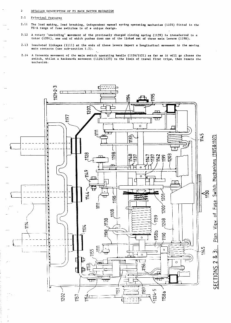
2 DETAILED DESCRIPTION OF FS M A I N SWITCH MECHANISM
2.1 P r i n c i p a l F e a t u r e s
2.11 The load making, l oad b r eak ing , independent manual s p r i n g ope ra t i ng mechanism (1105) f i t t e d i n t h e FS-A range of f u s e sw i t ches is of a unique des ign .
2.12 A r o t a r y "unwinding" movement of t h e p r ev ious ly charged c l o s i n g s p r i n g (1139) is t r a n s f e r r e d t o a r o t o r (1201), one end of which pushes down one of t he l i nked s e t of t h r e e main l e v e r s (1198).
2 -13 I n s u l a t e d l i n k a g e s (1111) a t t h e ends of t h e s e l e v e r s impart a l o n g i t u d i n a l a v e m e n t t o t h e m v i n g main c o n t a c t s ( s e e sub-sec t ion 1.2).
2.14 A forwards movement of t h e main sw i t ch o p e r a t i n g handle (112611121) a s f a r as i t v i l l go c l o s e s t h e sw i t ch , w h i l s t a backwards movement (112611123) t o t he l i m i t of t r a v e l f i r s t t r i p s , t hen r e s e t s t h e mechanism.

2.2 Opera t ing Sequence
2.21 With t h e mechanism i n t h e OFF p o s i t i o n , b u t n o t RESET, t h e o p e r a t i n g handle (1126/1122) is pushed f u l l y back t o t h e RESET (1123) p o s i t i o n .
2.22 The an t i -c lockwise motion of t h e h a n d l e ( l o o k i n g from t h e l e f t ) a s it is pushed backwards is c o n v e r t e d , by l i n k a g e s and g e a r s (1194), i n t o a c l o c k w i s e r o t a t i o n ( looking from t h e l e f t ) of t h e main s v i t c h main s h a f t (1133). The d i s c r a c h e t (1200) r o t a t e s v i t h t h e s h a f t u n t i l i t l a t c h e s a g a i n s t two d r i v e p i n s on t h e r o t o r (1201). A s t o p l e v e r (1147) on t h e main s h a f t t h e n comes a g a i n s t a s t o p p i n (1137) on t h e main frame (1108) assembly t o p r e v e n t f u r t h e r r o t a t i o n of t h e main s h a f t . The mechanism is now f u l l y RESET.
2.2 d&grambA': Mainswitch OFF
2.2&agrambB': Mainswitch RESET n
2.23 The o p e r a t i n g handle (112611123) i s then moved forwards smoothly t o the ON p o s i t i o n (1121).
2.24 The main swi tch main s h a f t (1133) r o t a t e s a n t i - c l o c k w i s e ( l o o k i n g f r a n t h e l e f t ) , c a r r y i n g round t h e c l o s i n g s p r i n g winding l e v e r (1138) t o wind t h e c l o s i n g s p r i n g (1139) from its l e f t hand end , and t h u s charge i t . The r i g h t hand end of t h e c l o s i n g s p r i n g a t t e m p t s t o p u l l round t h e d i s c r a t c h e t d r i v e

l e v e r (11401, t o which i t i s secured, but the d i s c r a t c h e t i s held back by the pins on the r o t o r (1201) which i s i n tu rn secured by the r o t o r r e l e a s e ca t ch (1199) which i s mounted on the main frame (1108) assembly.
When the main s h a f t (1133) has r o t a t e d t o the pos i t ion a t which the c los ing spr ing (1139) i s f u l l y charged, a r e l e a s e l e v e r (1142) on the s h a f t disengages the r o t o r re leaac catch (1199). t o r e l e a s e the r o t o r (1201). The r o t o r , under the pressure of the c los ing spr ing, rapidly r o t a t e s anti-clockwise ( looking f r m the l e f t hand s i d e ) through 1 8 0 ~ . Aa i t does so, one end of it pushes down on t h e c e n t r e main l eve r (1198) of t he 3 phase main l eve r assembly. Insulated l i nks (1111) a t the ends of t he main l e v e r s ope ra t e t o c l o s e the c o n t a c t s (1101/1102) a s described in sub-section 1.2. The t r i p ca t ch (1144) engages above the c e n t r e main l e v e r t o prevent the twitch r eopen ing under the in f luence of the opening sp r ings (1145). The s t o p l eve r (1147) and s t o p pin (1137) prevent t h e main s h a f t revolving too f a r i n the anti-clockwLse d i r e c t i o n . The r o t o r is now poised ready f o r the next c los ing opera t ion. The r o t o r a r r e s t o r sp r ing c a t c h (1213) ensures t h a t the ro to r does not come to r e s t i n a pos i t i on which might i n t e r f e r e with the subsequent opening movement of the c e n t r a l main l eve r (1198).
Mainswitch moves t o ON
2.2diagram'D' - Mainswitch ON

2.26 To manua l ly t r i p t h e s w i t c h . t h e o p e r a t i n g h a n d l e (1126/1121) is pushed back p a r t way, and t h e main s h a f t (1133) r o t a t e s c l o c k w i s e ( l o o k i n g from t h e l e f t ) . A r e v e r s e mot ion t r i p l e v e r (1147) on t h e main s h a f t pushes a s l i d i n g r e v e r s e m o t i o n t r i p b o l t (1148) . which pushes t h e t r i p c a t c h (1144) c l e a r o f t h e main l e v e r . F reed from t h i s c o n s t r a i n t , t h e main l e v e r assembly (1198) r i s e s under t h e i n f l u e n c e o f t h e open ing s p r i n g s (1145) t o s e p a r a t e t h e c o n t a c t s (1101/1102) t o t h e OFF p o s i t i o n .
2.27 When t h e mechanism i s t r i p p e d by t h e blowing of a f u s e o r f u s e s ( 3 1 1 ) , t h e s t r i k e r p i n ( s ) c a u s e t h e t r i p b a r (1112) t o r i s e , and a t r i p l e v e r (1149) pushes t h e t r i p c a t c h (1144) c l e a r and t h e o p e r a t i o n i s then a s d e s c r i b e d i n t h e l a s t s e n t e n c e of p a r a g r a p h 2.26.
2.28 F u r t h e r backwards manual movement of t h e o p e r a t i n g h a n d l e r e p e a t s t h e RESET sequence d e s c r i b e d i n p a r a g r a p h s 2 .21 , 2.22.
2.29 The mechanism ON/OFF i n d i c a t i o n v i s i b l e t h r o u g h t h e t a n k window (1130) i s mounted d i r e c t l y on t h e s h a f t of t h e main l e v e r assembly ( 1 1 9 8 ) , s o t h a t i t p o s i t i v e l y i n d i c a t e s t h e p o s i t i o n of t h e mechanism (1105) and no t mere ly t h a t of t h e h a n d l e ( 1 1 2 6 ) .

DETAILED DESCRIPTION OF TRANSFORMER EARTH SWITCH
Pr inc ipa l Features
The f a u l t making, load breaking, independent manual e a r t h s v i t c h mechanism (1107) is of a conventional over toggle sp r ing type.
It d r i v e s a s i n g l e blade (1197) which s h o r t s together th ree s e t s of sp r ing con tac t s (1104) vhich a r e i n tu rn mounted on the outgoing c i r c u i t bushings (1114). A viping con tac t (1195) a t t he end of t h e b lade gives an e a r t h connection through t o the ear thed metalvork of the tank (1115).
Operating Sequence I
When t h e e a r t h s v i t c h handle (112611125) is moved downwards f u l l y t o the EARTH ON pos i t ion (LIZ&), the e a r t h switch mechanism s h a f t (1150) r o t a t e s c lockv i se (looking f r e e the l e f t ) and the sp r ing compression l eve r (1151) compresses the sp r ings (1152) between the two limbs of the toggle l e v e r (1153). As the sp r ings pass the point of maximum compression, t he toggle l eve r is forced to p ivo t downvards, d r i v i n g the toggle d r i v e l i n k (1154) and thus the s t a r point blade (1197) i n t o contact v i t h the sp r ing con tac t s (1104). The sp r ings cannot f u l l y expand again , but push a g a i n s t t he "knee" of t h e toggle l inkage.
When the handle (1126/1124) is r a i s e d from EARTH ON t o OFF (1125). t he m t i o n of the mechanism is reversed. The sp r ings (1152) a r e re-compressed, then d r i v e t o break t h e toggle l inkage and open t h e swi tch (1197). Also, a nudger (1155) i s pivoted by the sp r ing compression l e v e r (1151) t o gfve a p o s i t i v e upwards d r i v e t o the s t a r point b lade assembly (1197/1157).
An ind ica t ion d r i v e l i n k (1156) from t h e s i d e arm (1157) of t he s t a r point blade assembly d r ives the EARTH ON i n d i c a t o r p l a t e (1196) vhich, i n t h e EARTH ON pos i t ion , s h i e l d s t h e OFF ind ica t ion (1210) i n the window (1130).
: ARTH ON"

earth switch OFF
"OFF"
SD-HI RANGE ERECTION INSTRUCTIONS
DELIVERY 6 ERECTION
Loading, Delivery and Unloading
"SO-HI" u n i t s may be c a r r i e d on open t r u c k s i f adequate ly secured and ta rpaul ined a g a i n s t t h e ves ther .
For speed and s a f e t y t h e u s e of a s m a l l c r a n e , f o r k l i f t o r o t h e r handling device to unload swi tchgear is recormended. The s a f e vorking load (SUt) should be a t l e a s t twice t h e t o t a l weight of any load t o be l i f t e d ; i n t h e c a s e of a c r a n e , t h i s shpyld be t h e SWL a t the lltsximum r a d i u s required by t h e s i t e l ayout .
A 6 m (20 f t ) circumference e n d l e s s s l i n g , SWL a t least twice the t o t a l w i g h t of any load t o be l i f t e d . looped under main s t r u c t u r a l components, should be used for c rane unloading. WARNING: Dw not loop the s l i n g under t h e f r o n t of an OCB l i d (2) wi thout f i r s t ensuring t h s t a l l four secur ing s c r e r (87) a r e t igh tened f u l l y home.
Do not at tempt t o o p e r a t e any i tem of swi tchgear u n t i l t h e appropr ia te e r e c t i o n , p repara t ion a d c o ~ n i s s i o n i n g procedures have been completed.
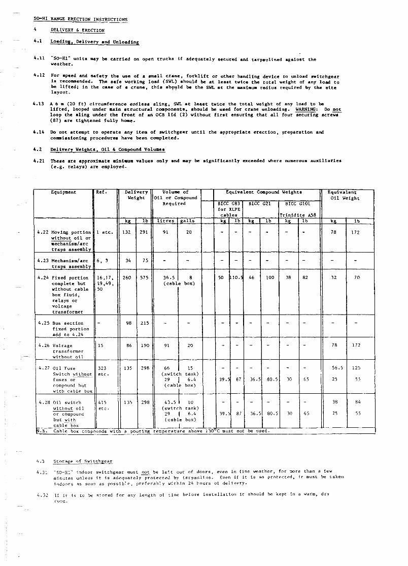
Delivery Weights. O i l & Compound Volumes
These a r e approximate minimum v a l u e s on ly and may be s i g n i f i c a n t l y exceeded h e r e numerous a u x i l i a r i e s (e.g. r e l a y s ) a r e employed.
Equipment Ref.
1.22 Moving p o r t i o n without o i l o r mechanism/arc t r a p s assembly
& .23 Mechanism/arc t r a p s assembly
i . 2 4 Fixed por t ion complete but without cab le box f l u i d , r e l a y s o r v o l cage transformer
4.25 Bus s e c t i o n f ixed port i o n add t o 4.24
6 . 2 6 V o l t a g e t r a n s f o r m e r v i t h o u t o i l
4.27 O i l f u s e S v i t c h vi thouc f u s e s o r compound b u t w i t h c a b l e b o ~
4.28 O i l s w i t c h w i t h o u t o i l o r compound
1 e t c .
6 , 3
16.17. 19.49, 50
323 e t c .
415 e t c .
Del ivery Weight il o r Compound
Required
l i t r e s g a l l s
9 1 20
- -
36.5 8 ( c a b l e box)
- -
9 1 2 0
6 6 15 ( s v i t c h t a n k )
29 1 6.4 ( c a b l e box)
I 43.5 10
( s v i t c h t a n k ) 29 1 6.4 ( c a b l e box)
IICC G83 I BICC G21
: must nor be u s e
4.3 S t o r a g e of Swi t chgea r
4.31 "SO-HI.' i ndoor s w i t c h g e a r must not be l e f t o u t of d o o r s , even i n f i n e v e a t h e r , f o r more than a few minu te s u n l e s s i t is a d e q u a t e l y p r o t e c t e d by t a r p a u l i n s . Even i f i t is s o p r o t e c t e d , i t must be t a k e n i n d o o r s a s soon a s p o s s i b l e , p r e f e r a b l y w i t h i n 24 h o u r s of d e l i v e r y .
4.32 I f i t i s t o be s t o r e d f o r any l e n g t h of t ime b e f o r e i n s t a l l a t i o n i t shou ld be kep t i n a varm, d r y room.

4.l - diagram 'A'
87
4.4 P r e p a r a t i o n o f Switchroom F l o o r ( f o r U n i s t r u t F o u n d a t i o n s )
4 .41 T h i s s e c t i o n c o v e r s t h e use of f i x e d p o r t i o n s and b u s b a r chambers v i t h i n t e g r a l b a s e p l a t e s , on " U n i s t r u t " f o u n d a t i o n r u n n e r s (181) . A I l t y p e s of u n i t , OCS, o i l s v i t c h , f u s e s w i t c h , busba r c a b l e box and b u s b a r v o l t a g e t r a n s f o m e r , a r e c o v e r e d .
F o u n d a t i o n d e t a i l s v a r y from swi t chboa rd t o s w i t c h b o a r d . R e f e r e n c e shou ld a lways k m d e t o t h e f o u n d a t i o n p l a n s u p p l i e d f o r t h e i n d i v i d u a l i n s t a l l a t i o n . .4 c a b l e t r e n c h o r c o n d u i t s , of s i z e and l a y o u t t o s u i t t h e c a b l e s t o be used , w i l l u s u a l l y be r e q u i r e d a t t h e r e a r of t h e swi t chboa rd . Rear a c c e s s f o r c a b l e j o i n t i n g w i l l a l s o be n e c e s s a r y . Where f i r w a l l s a r e i n s t a l l e d they o u s t be ex tended down i n t o t h e t r e n c h , o v e r s i z e gaps be ing l e f t f o r t h e i n s t a l l a t i o n of c a b l e d r t c t s , busba r t r u n k i n g s e t c . The h o l e s can be f i l l e d i n t o s i z e vhen a l l equ ipmen t i s i n p o s i t i o n .
4 .43 P r e p a r e a s u b - f l o o r 40 om (1 .518 i n ) below f i n i s h e d f l o o r l e v e l , v i t h c h a s e s ( 1 8 2 ) a f u r t h e r 7 0 o m (2 .112 i n ) deep by 1 0 0 m ( 4 i n ) v i d e a s shown i n d i a g r a m 'B'. Note t h a t f o r c i r c u i t b r e a k e r f i x e d p o r t i o n s t h r e e c h a s e s ( 1 8 2 ) . a t c e n t r e s of 1 8 0 mm + 390 mm + 430 nm from t h e t r e n c h edge w i l l be r e q u i r e d . A l l o t h e r u n i t s i e q u i r e o n l y t h e f i r s t two c h a s e s . The l e n g t h of t h e c h a s e s must be a t l e a s t t h e t o t a l u l t i m a t e l e n g t h of t h e s w i t c h b o a r d , i n c l u d i n g a n y f u t u r e e x t e n s i o n s ~ i c h may be unde r c o n s i d e r a t i o n .
4 .44 P l a c e t n e U n i s t r u t r u n n e r s (181) i n t h e i r a p p r o x i m a t e p o s i t i o n s i n t h e c a s e s a d bu rn 50 mm ( 2 i n )
g a p s i n t h e foam p l a s t i c f i l l e r a t a p p r o x i m a t e l y 9 6 0 mm (3 ,7 , in ) c e n t r e s , u s i n g a blowlamp. Using t h e Mlo s p r i n g n u t s (183) p r o v i d e d , f i x t i e bar j i g s ( 1 8 4 ) t o t h e f o u n d a t i o n r u n n e r s (181) a c 940 mm ( 3 7 i n ) c e n t r e s a s shown i n d i ag rams 'C' and 'D'.

E r e c t a f ixed datum, r e p r e s e n t i n g t h e f i n i s h e d f l o o r l e v e l of 40 mm (1.5/8 i n ) above the prepared sub- f l o o r , ha l f way along the switchboard. Take a water l e v e l gauge c o n s i s t i n g of tvo graduated j a r s connected by a f l e x i b l e pipe of a t l e a s t 314 of t o t a l switchboard length (diagram 'E") and f i l l v l t h water , t ak ing c a r e t o remove a l l t rapped a i r from the pipe by l e t t i n g t h e pipe l i e f l a t on t h e f l o o r . P lace both j a r s on t h e datum and n o t e t h e i r common read ing (on s h o r t switchboards a s p i r i t l e v e l and long s t r a i g h t edge may be used) .
Check by measuring cor responding d i a g o n a l s t h a t t h e U n i s t r u t f t i e bar assembly (1811184) f s ' square ' . P o s i t i o n small p ieces of s t e e l p l a t e under t h e l e v e l l i n g screws, and ensure t h a t the c e n t r e of t h e r e a r runner is 180 mm from t h e c a b l e t r e n c h edge a t both ends. Where tvo o r -re l e n g t h s of U n i s t r u t a r e t o be but ted end t o end. they must l i n e up e x a c t l y .
Leaving one of the water l e v e l j a r s on t h e datum, p lace t h e o t h e r on top of each runner (181) i n t u r n along the length of t h e s v i t c h b o a r d , each time a d j u s t i n g the l o c a l jacking screws u n t i l t h e prev ious ly noted common water l e v e l is a t t a i n e d . T h i s w i l l r e s u l t i n t h e runners being l e v e l over t h e f u l l l ength of the sv i tchboard . A t o l e r a n c e of p l u s o r minus 0.5 nm is acceptable.
Grout the U n i s t r u t runners (181) i n p o s i t i o n , t h e grout f i l l i n g t h e chases and reaching approximate ly ha l f vay up t h e U n i s t r u t s i d e s (diagram 'F'). When t h e grout is f u l l y s e t , remove t h e t i e b a r s (184) and sprung nuts (183) from t h e runners .
F l o a t the f i n i s h e d f l o o r between t h e runners (181) , t h e l e v e l co inc id ing w i t h t h e tops of t h e runners . Take c a r e not to g e t c o n c r e t e i n t o t h o s e p a r t s of t h e channels from which the foam has been removed. When the switchboard f l o o r a r e a has s e t , f l o a t t h e rest of t h e f l o o r using t h e f i n i s h e d a r e a a s datum.
Erec t ion of Fixed P o r t i o n s and o t h e r Uni t s ( o n U n i s t r u t )
This s e c t i o n covers the use of f ixed p o r t i o n s or busbar chambers, v i t h l n t e g r a l b a s e p l a t e s , on "Uniscrut" foundation runners . A l l types of u n i t , OCB, o i l switch, fuse s v i t c h , busbar c a b l e box and busbar vo l tage t ransformer , a r e covered.
Using the foundation plan f o r the s p e c i f i c sv i tchboard a s a guide, burn 50 mm ( 2 i n ) gaps i n t h e Unistruc (181) foam p l a s t i c f i l l e r a t t h e f i x e d p o r t i o n f i x i n g p o i n t s v i t h a blowlamp. P o s i t i o n t h e 3 1 8 in spr ing nuts ( 1 8 3 ) i n the runners a t t h e s e p o i n t s .

1 I w w
i OZE
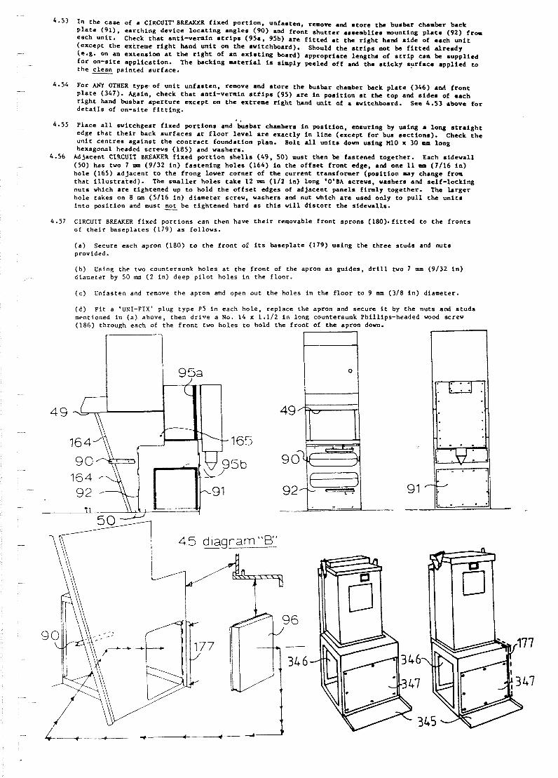
4-53 I n t h e cane of a CIRCUIT'BREAKLR f i x e d p o r t i o n , unfas ten , removc and s t o r e t h e busbar chamber back p l a t e (91). e a r t h i n g d e v i c e l o c a t i n g a n g l e s (90) and f r o n t s h u t t e r assemblies w u n t i n g p l a t e (92) from each u n i t . Check t h a t anti-vermin S t r i p s (9%. 9%) a r e f i t t c d a t t h c r i g h t hand s i d e of each u n i t (except t h e extreme r i g h t hand u n i t on t h e switchboard). Should t h e s t r i p s not be f i t t e d a l r e a d y ( e - g - on an e x t e n s i o n a t the r i g h t of a n e x i s t i n g board) a p p r o p r i a t e lengths of s t r i p can be s u p p l i e d f o r on-s i te a p p l i c a t i o n . The backing = a t e r i a l is simply peeled o f f and t h e s t i c k y s u r f a c e a p p l i e d t o t h e clean pain ted s u r f a c e .
4.54 For ANY OTHER type of u n i t u n f a s t e n , remove and s t o r e t h e busbar chamber back p l a t e (346) an4 f r o n t p l a t e (347). Again, check t h a t anti-vermin s t f i p s (95) a r e i n p o s i t i o n a t the top and s i d e s of each r i g h t hand busbar a p e r t u r e except on t h e extreme r i g h t hand u n i t of a a r i tchboard . See 6 - 5 3 above f o r d e t a i l s of on-s i te f i t t i n g .
I '
6 - 5 5 P lace a l l s v i t c h g e a r f ixed p o r t i o n s and busbar chambers i n p o s i t i o n , ensur ing by us ing a long s t r a i g h t edge thac t h e i r back s u r f a c e s a t f l o o r l e v e l a r e e x a c t l y i n l i n e (except f o r bus s e c t i o n s ) . Check t h e u n i t c e n t r e s a g a i n s t t h e c o n t r a c t foundat ion plan. Bolt all u n i t s down using M10 x 30 mm long hexagonal headed screws (185) and washers.
4.56 Adjacent CIRCUIT BREAKER f i x e d p o r t i o n s h e l l s (49 , 50) must then be fas tened toge ther . Each s i d e w a l l (50) has t v o 7 mm (9132 i n ) f a s t e n i n g h o l e s (164) i a the o f f s e t f r o n t edge, and one 11 mm (7 /16 i n ) h o l e (165) a d j a c e n t t o t h e f rong lower c o r n e r of t h e c u r r e n t t ransformer ( p o s i t i o n may change from t h a t i l l u s t r a t e d ) . The s m a l l e r h o l e s t a k e 12 nan (112 i n ) long 'O'BA screws, washers and s e l f - l o c k i n g n u t s which a r e t i g h t e n e d up t o hold t h e o f f s e t edges of ad jacent panels f i rmly t o g e t h e r . The l a r g e r ho le takes on 8 cim (5116 i n ) d iameter screw, washers and nut which a r e used only t o p u l l t h e u n i t s i n t o p o s i t i o n and must nor be t i g h t e n e d hard a s t h i s w i l l d i s t o r t t h e s idewal l s .
4.57 CIRCUIT BREAKER f ixed p o r t i o n s can then have t h e i r removable f r o n t aprons ( 1 8 0 ) . f i t t & t o t h e f r o n t s of t h e i r b a s e p l a t e s (179) a s fo l lows .
( a ) Secure each apron (180) t o t h e f r o n t of its basepla te (179) u s i n g t h e t h r e e s t u d s and m t s provided.
( b ) Using t h e cvo countersunk h o l e s a t the f r o n t of the apron a s g u i d e s , d r i l l tvo 7 mm (9132 i n ) diameter by 50 m ( 2 i n ) deep p i l o t ho les i n the f l o o r .
( c ) Unfasten and remove t h e apron atid open o u t the ho les i n the f l o o r t o 9 mm (318 i n ) d iameter .
( d ) F i t a 'UN-FIX' plug t y p e P5 i n each h o l e , rep lace the apron and secure i t by t h e nu ts a d s t u d s mentioned i n ( a ) above, t h e n d r i v e a No. 14 x 1.112 i n long countersunk Phil l ips-headed wood screw (186) through each of the f r o n t tw h o l e s t o hold t h e f r o n t of the apron down.
4.58 F i t p i e c e s of c l ip -on p l a ~ t i c c o v e r t o any exposed l e n g t h s of U n i s t r u t runner . e .g . where p r o v i s i o n h a s been made f o r f u t u r e e x t e n s i o n s o r a d j a c e n t t o bus s e c t i o n f i x e d p o r r i o n s .
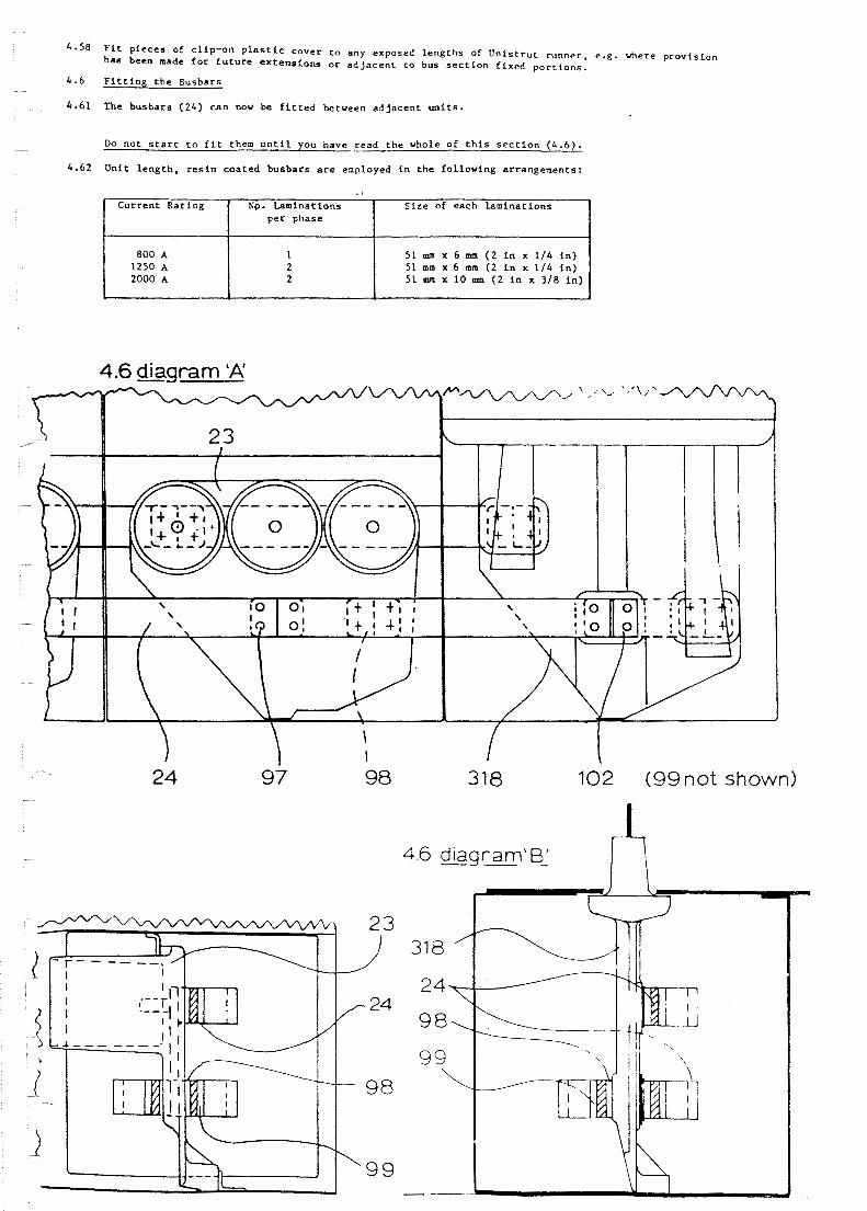
4 .6 F i t t i n g t h e Busbar s
4 - 6 1 The b u s b a r s (24 ) c a n now be f i t t e d between a d j a c e n t u n i t s .
Do n o t s t a r t t o f i t them u n t i l you have r e a d t h e whole o f t h i s s e c t i o n (4 .6 ) .
4 - 6 2 U n i t l e n g t h , r e s i n c o a t e d b u s b a r s are employed i n t h e f o l l o w i n g a r rangement s :
318 102 (99not shown)
. I
C u r r e n t R a t i n g
800 A 1250 A 2000 A
NQ. Lamina t ions p e r phase
1 2 2
S i z e of each l a m i n a t i o n s
51 mm x 6 mm ( 2 i n x 114 i n ) 51 mm x 6 mm ( 2 i n x 114 i n ) 51 mrtr x 1 0 mm ( 2 i n x 318 i n )

4.67 I n t h e c a s e of c i r c u i t b r e a k e r f i x e d P O ~ C ~ O ~ S , r e p l a c e and s e c u r e t h e e a r t h i n g d e v i c e l o c a t i n g a n g l e s ( 9 0 ) o n t h e s i d e w a l l s ( 5 0 ) .
4 . 6 8 F i t t h e I n t e r - u n i t s e c t i o n s o f t h e = i n s w i t c h b o a r d e a r t h bar a l o n g t h e r e a r of t h e b u s b a r c h a m b e r s ,
e n s u r i n g t h a t t h e e a r t h c o n n e c t i o n f r o m e a c h f i x e d p o r t i o n i s c o n n e c t e d t o t h e main e a r t h b a r . Bond t h e s v i t c h b o a r d e a r t h bar t o t h e s u b s t a t i o n e a r t h a c c o r d i n g t o l o c a l p r a c t i c e .
4 6 diagram 'D' i
4.6 - diagram '0' i i
4 - 6 9 Note t h a t when a s w i t c h b o a r d I s t o be e x t e n d e d , t h e new u n i t s c a n 5. e r e c t e d w h i l s t t h e end p l a t e ( 9 6 ) o f t h e o r i g i n a l b o a r d r e o ~ i n s i n p o s i t i o n . R e m c ~ b e r t i m t a n t i - v e r m i n s e a l i n g s t r i p s ( 9 5 ) m u s t be p l a c e d b e t w e e n t h e o l d a n d new u n i t s . Chen t h e new e q u i p m e n t i s c o m p l e t e , t h e o r i g i n a l s w i t c h b o a r d i s made d e a d and t h e b u s b a r s a r e e a r t h e d . T h e b u s chamber back p l a t e ( 9 1 , 3 4 6 ) o f t h e o r i g i n a l end u n i t i s r e m o v e d , t h e end p l a t e ( 9 6 ) i s moved t o t h e new end u n i t and b u s b a r s ( 2 4 ) a r e f i t t e d b e t w e e n t h e < ~ d ] ; l c c n t new and o r i g i n a l u n i t s . Ti le normal c o i - p i c t i o n p r o c r d s t r e s a r e the:> f ~ l l o u i ~ d .
4.7 J o i n t i n g o f Cab les
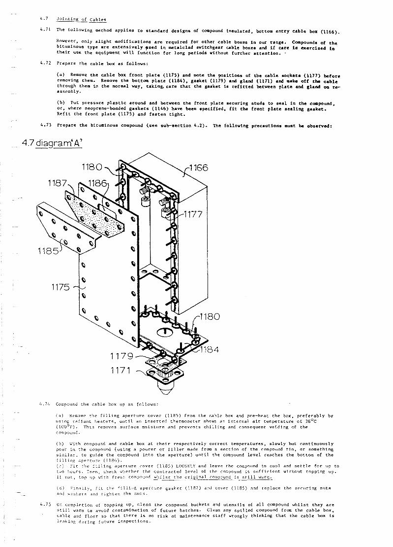
'4.71 The f o l l o v i n g w t h o d a p p l i e s t o s t a n d a r d d e s i g n s of compound i n s u l a t e d , bot tom e n t r y c a b l e box (1166).
However, o n l y s l i g h t m o d i f i c a t i o n s are r e q u i r e d f o r o t h e r c a b l e boxes i n o u r r ange . Compounds of t h e b i tuminous type a r e e x t e n s i v e l y p e d i n m e t a l c l a d s w i t c h g e a r c a b l e boxes and i f care is a e r c i s e d i n t h e i r u s e t h e equipment v i l l f u n c t i o n f o r l o n g p e r i o d s without f u r t h e r a t t e n t i o n . .
4 .72 P r e p a r e t h e c a b l e box a s f o l l o w s :
( a ) Remove t h e c a b l e box f r o n t p l a t e (1175) and n o t e t h e p o s i t i o n s of t h e c a b l e s o c k e t s (1177) b e f o r e removing them. Remove t h e bo t tom p l a t e (1184) . g a s k e t (1179) and g land (1171) and m a k e o f f t h e c a b l e th rough them i n t h e normal way, t a k i n k care t h a t t h e g a s k e t is r e f i t t e d b e t v e e n p l a t e and g l a n d oa r c assembly.
( b ) Pu t p r e s s u r e p l a s t i c a round and b e t v e e n t h e f r o n t p l a t e s e c u r i n g s t u d s t o s e a l i n t h e compound, o r , where neoprene-bonded g a s k e t s (1166) have been s p e c i f i e d , f i t t h e f r o n t p l a t e s e a l i n g g a s k e t . R e f i t t h e f r o n t p l a t e (1175) and f a s t e n t i g h t .
4 . 7 3 P r e p a r e t h e b i tuminous compound (see s u b s e c t i o n 4 . 2 ) . The f o l l o w i n g p r e c a u t i o n s must be obse rved :
4 . 7 6 Compound t h e c a b l e box up a s f o l l o w s :
( a ) Remove t h e f i l l i n g a p e r t u r e c o v e r (1185) from t h e c a b l e box and pre-heat t h e box, p r e f e r a b l y by u s i n g r a d i a n t h e a t e r s , u n t i l an i n s e r t e d thermometer shows an i n t e r n a l a i r t e m p e r a t u r e o f 3 8 O ~ ( 1 0 0 ~ ~ ) . T h i s removes s u r f a c e m o i s t u r e and p r e v e n t s c h i l l i n g and consequen t v o i d i n g of t h e compound.
( b ) With compound and c a b l e box a t t h e i r r e s p e c t i v e l y c o r r e c t t e m p e r a t u r e s , s l o w l y but c o n t i n u o u s l y pour i n t h e coopound ( u s i n g a p o u r e r o r f i l l e r made f r a n a s e c t i o n of t h e compound t i n , o r someth ing s i n i l a r , t o gu ide t h e coopound i n t o t h e a p e r t u r e ) u n t i l t he compound l e v e l r e a c h e s t h e bot tom of t h e f i l l i n g a p e r t u r e (1186) . ( c ) F i t t he f i l l i n g a p e r t u r e c o v e r ( 1185 ) LOOSELY and l eave the compound t o c o o l and s e t t l e f o r up t o two hours . Then, check whether t h e c o n t r a c t e d l e v e l of the compound is s u f f i c i e n t w i t h o u t t o p p i n g up. i f n o t , t o p up ~ 5 t h f r e s h compound w h i l s t t h e o r i g i n a l compound i s s t i l l warm.
( d l Finally, f i t t h e f i l l i r l g a p e r t u r e g a s k e t (1187) and cover (1185) and r e p l a c e t h e s e c u r i n g n u t s a n d v a s h e r s and t i g h t e n the n u t s .
4 . 7 5 On comple t ion of topp ing up, c l e a n t h e compound bucke t s and u t e n s i l s of a l l compound v h i l s t t h e y a r e s t i l l vann t o avo id c o n t a m i n a t i o n of f u t u r e b a t c h e s . Clean any s p i l l e d compound £ r a n t h e c a b l e box, c a b l e and f l o o r s o t h a t t h e r e i s no r i s k of maintenance s t a f f v rong ly t h i n k i n g t h a t t h e c a b l e b x is l e a k i n g d u r i n g f u t u r e i n s p e c t i o n s .
DELIWRY 6 ERECliIOH (0s-A0 b FS-AO)
Loading, De l ive ry , Unloading 6 S t o r a g e
Outdoor u n i t s may be c a r r i e d on unshee ted v e h i c l e s f o r s h o r t journeys, o r s t o r e d ou tdoors f o r s h o r t p e r i o d s , bu t they should n o t e regarded a s f u l l y weatherproof u n t i l the prqcedures desc r ibed i n t h i s s e c t i o n and s e c t i o n 7 o f t h i s manual have been s a t i s f a c t o r i l y completed. Prolonged s t o r a g e should be i n a warm, d ry room.
It is p o s s i b l e f o r two men t o l o a d , unload and e r e c t t h i s h i t c h g e a r v i t h o u t the use of l i f t i n g and hand l ing equipeient. However, f o r speed and s a f e t y t h e uae of a s m a l l c rane , f o r k l i f t o r s i m i l a r equipment is recommended. The s a f e working load (SVL) shou ld be a t l e a s t m i c e t h e t o t a l weight of any load t o be l i f t e d ; i n t h e case of a c r a n e , t h t s should be t h e SYL a t t h e aaximtlm o p e r a t i n g r a d i u s requ i red by t h e s i t e l ayou t .
A 6 m (20 f t ) c i rcumference e n d l e s s s l i n g of mani l l a rope o r s u i t a b l e woven s y n t h e t i c m a t e r i a l s . SWL a t l e a s t twice t h e t o t a l weight of t h e swi tch , should be looped under main s t r u c t u r a l components of t h e u n i t t o c r a n e l i f t i t .
Ih not a t t empt t o o p e r a t e any i t em of s v i t c h g e a r u n t i l t h e a p p r o p r i a t e e r e c t i o n , p r e p a r a t i o n and commissioning p rocedures have been completed.
k l i v e r y Weight, O i l and Compound Q u a n t i t i e s
These a r e approximate v a l u e s on ly .
Weight of FS-AO, busbar chamber and c a b l e box, v i t h no o i l o r compound : 131 k g (289 l b ) .
Volume of FS-A0 o i l t ank : 66 l i t re (14.5 g a l l ) . Equ iva len t weight of o i l : 56.5 kg (126 l b ) .
Weight of 0s-AO, busbar chamber and c a b l e box, wi th no o i l o r compound : 136 kg (295 l b ) .
Volume of 0s-A0 o i l tank : 63.5 l i t r e (9.6 g a l l ) . Equ iva len t v e i g h t of o i l : 37.2 kg ( 8 2 l b ) .
Volume of r e a r cab le box (FS o r 0 s ) : 28 l i t r e (6.2 g a l l ) . Fqu iva len t weight of compound : 27 kg ( 6 0 l b ) .
Erec t ion : Smooth Concrete F loor
Uni t s may be e r e c t e d d i r e c t l y o n t o a smooth c o n c r e t e f l o o r and secured wi th rag b o l t s o r s i m i l a r p r o p r i e t a r y f i t t i n g s . However, t h i s r e q u i r e s t h a t t h e f l o o r has a smooth, t rowel led f i n i s h t o w i t h i n t h e l i m i t s of a nominally f l a t f l o o r a s s p e c i f i e d i n B r i t i s h Standard Code of P r a c t i c e C.P.206, Pt.1. 1965, 1.e. + 1/R in . i n 10 f t . (t 3 m i n 2880 om). - I f duch a f l o o r f i n i s h can be a c h i e v e d , t h e u n i t f i x i n g ho le c e n t r e s may then be marked ou t i n accordance v i t h t h e foundat ion plan. Note t h a t d u c t s o r a t r e n c h w i l l be requ i red a t the r e a r of the switchboard t o accommodate c a h l e s approaching from below. Take c a r e t o check t h a t t h e d iagona l measurements between c e n t r e s match, showing t h a t t h e y have been marked ou t "square".
A l t e r n a t i v e l y , where o n l y two o r t h r e e p a n e l s a r e t o be employed, they may be b o 1 t e d . u ~ t o g e t h e r and t h e husbars f i t t e d ( s e e below), and t h e u n i t s themselves may be used t o mark the f i x i n g c e n t r e s on t h e f l o o r .
Once t h e f i x i n g c e n t r e s have been de te rmined , d r i l l ou t c l e a r a n c e ho les f o r 12 mm (1/2 i n ) d i a . UNI-FIX o r s i m i l a r rag-bol t- type f l o o r f i x i n g s (1170). Grout i n t h e b o l t s wi th approximately 25 m ( 1 i n ) of th readed shenk pro t rud ing above f i n i s h e d f l o o r l e v e l . Leave t o s e t .
F i t t h e removable f e e t (1383) benea th t h e b o t t o m of t h e busbar chambers, using t h e n u t s and washers provided.
Lover t h e s v i t c h p e a r u n i t s o v e r t h e p r o t r u d i n g rag b o l t shanks. The b o l t s should be c e n t r a l i n the h o l e s i n t h e u n i t f e e t . Add t h e washers and n u t s t o t h e f i x i n g b o l t s and s c r e v down l o o s e l y , no t ing t h a t t h e r e i s no d i s t o r t i o n of the u n i t bod ies . Check t h e h o r i z o n t a l s u r f a c e s of the u n i t s with a s p i r i t l e v e l , and check t h a t a l l f e e t a r e r e s t i n g f i r m l y on t h e f l o o r . I f any u n i t is not f i n c and l e v e l , l i f t i t c l e a r and add packing washers t o t h e r e l e v a n t f i x i n g b o l t o r b o l t s .
A s each u n i t i s s a t i s f a c t o r i l y l o c a t e d and l e v e l l e d . f a s t e n it down f i r m l y to the f i x i n g b o l t s . Ib not f o r g e t t o place the g a s k e t s hetween t h e husbar chamber f l a n g e s (1378) of ad jacen t u n i t s , and f a s t e n t h e f l a n g e s t o g e t h e r v i t h t h e n u t s , b o l t s and washers provided.
F i t the ra insheds (1382) (where p rov ided) t o t h e t o p s of the fas tened f l a n g e s , t o prevent r a i n r e s t i n g on t h e t o p edges of the g a s k e t s he tveen u n i t s .
Erec t ion : U n i s t r u t Foundat ions
I f i t i s f e l t t h a t a f l o o r a s smooth a s t h a t d i scussed i n paragraph 5.31 cannot be guaran teed , or i f a p a r t i c u l a r l y long switchboard i s invo lved , we recornend t h a t UNISTRUT channe l s , r e f e r e n c e P3200 (1811, and s p r i n g n u t s , r e f e r e n c e P1008 (183) be employed t o ensure a l e v e l founda t ion . UNISTRUT f i t t i n g s a r e a v a i l a b l e from o u r s e l v e s , a t an a d d i t i o n a l c o s t pe r switchboard panel , o r d i r e c t l y from:
UNISTRUT Div i s ion of G K N Limited, 03-45 Rroadvater Road, Welvyn Garden C i t y , Her t s . , England.

Prepare a sub-floor 40 mm (1.5/8 i n ) below the f in i shed f l o o r l eve l . n t h chases a f u r t h e r 70 mm (2.3/4 i n ) deep by 100 m (4 i n ) v ide a t 281 nun ( l l .1116 i n ) cen t r e s . running a t l e a s t the t o t a l u l t ima te length of the switchboard, including any f u t u r e extensions which may be under considera t ion.
Note t h a t ducts o r a t rench w i l l be required a t the r e a r of the switchboard to accommodate cab le s approaching from below.
Place the Unis t ru t runners (181) i n t h e i r approximate posi t ions i n the chases (182) and burn 50 mm (2 i n ) gaps i n the foam p l a s t i c f i l l e r a t roughly 509 nun (20 i n ) cen t r e s , us ing a blovlamp o r gas torch. Using the sp r ing nuts (183) provided, f i x t i e bar J i g s (1377) t o the foundation runners a t these gape. By using a s t r a i g h t edge, and by measuring corresponding diagonals , check t h a t t h e ~ n i s t r u t / t i e bar assembly is "square". Pos i t ion s m a l l p ieces of s t e e L . p l a t e o r s i m i l a r mater ia l under the t i e bar l e v e l l i n g sc revs and ensure t h a t the long i tud ina l c e n t r e l i n e of t he r e a r runner i s 80 mm (3.1/8 i n ) Ira. the t rench edge a t both ends. Note t h a t h e r e tvo o r -re l eng ths of Un i s t ru t a r e to be butted end to end, they must l i n e up exact ly .
Using a s p i r i t l e v e l , a s t r a i g h t edge and the t i e bar l e v e l l i n g screvs , ensure t h a t the U n i s t r u t / t i e bar assembly is l e v e l i n both d i r e c t i o n s . Grout i n the runners f i l l i n g the chases with cement grout m i x and ca r ry ing the grout ha l f way up the ou t s ides of t he runners. Leave the grout t o s e t hard, then remove the t i e bar j i g s and sp r ing n u t s from the runners. F loa t t he f in ished f l o o r betveen the runners, t he l e v e l coinciding with the tops of t he runners but not overflowing them. Do not l e t the concrete ge t i n t o the previously b u r n e d a u t p a r t s of t he runners. When the switchboard f l o o r a rea has s e t , use i t a s a datum t o f l o a t and l e v e l the r e s t of the svi tchboard f loo r .
Using the switchboard foundation plan a s a guide, burn 50 mm ( 2 i n ) gaps i n the foam p l a s t i c f i l l e r of t h e runners a t the required f i x i n g po in t s , us ing a blow lamp o r gas torch. Pos i t ion the MI0 s p r i n g nu t s (183) i n the runners a t t hese points . F i t t he removable f e e t (1383) beneath the busbar chambers (1368) us ing t h e nu t s and vashers provided.
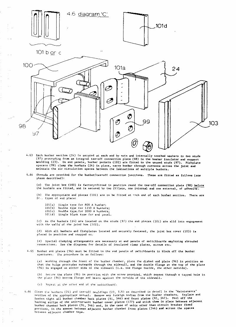
4.63 Each busba r s e c t i o n (24) i s s e c u r e d a t each end by n u t s and i n t e r n a l l y t o o t h e d washe r s t o m o s t u d s ( 9 7 ) p r o t r u d i n g from a n i n t e g r a l tee-off c o n n e c t i o n p l a t e (98 ) i n t h e busba r i n s u l a t o r and s u p p o r t moulding ( 2 3 ) . On end p a n e l s , busba r p a c k e r s (102) are f i t t e d t o t h e unused s t u d s (97). F i s h p l a t e s p a c e r s ( 9 9 ) clamp t h e b u s b a r s ( 2 4 ) i n p l a c e , c a r r y busba r th rough c u r r e n t s a c r o s s t h e j o i n t and m a i n t a i n t h e a i r c i r c u l a t i o n s p a c e s between t h e l a m i n a t i o n s of m u l t i p l e busba r s .
4.64 Shrouds a r e p rov ided f o r t h e b u s b a r l t e e - o f f c o n n e c t i o n j u n c t i o n s . These are f i t t e d a s f o l l o w s (one phase d e s c r i b e d ) :
( a ) The j o i n t box (100) i s f a c t o r y - f i t t e d i n p o s i t i o n round t h e t ee -o f f c o n n e c t i o n p l a t e (98 ) b e f o r e t h e b u s b a r s a r e f i t t e d , and is s e c u r e d by two f i l l e t s , one i n t e r n a l and one e x t e r n a l . of a d h e s i v e .
( b ) The a p p r o p r i a t e end p i e c e s ( 1 0 1 ) a r e t o be f i t t e d a t -ch end of each busba r s e c t i o n . There a r e f c . t y p e s of end p i e c e :
1 0 1 ( a ) S i n g l e t y p e f o r 8 0 0 A b u s b a r ; 101(b ) Double t y p e f o r 1250 A b u s b a r s ; 1 0 l ( c ) Double t y p e , f o r 2000 A b u s b a r s ; 1 0 1 ( d ) S i n g l e b l ank t y p e f o r end pane l .
( c ) AS t h e busba r s ( 2 4 ) a r e l o c a t e d on t h e s t u d s ( 9 7 ) t h e end p i e c e s (101) a r e s l i d i n t o engagement w i t h t h e wa l l s ' of t h e j o i n t ' b o x (100) .
( d l With a l l b u s b a r s and f i s h p l a t e s l o c a t e d and s e c u r e l y f a s t e n e d , t h e j o i n t box c o v e r (103) i s p laced i n p o s i t i o n and snapped on.
( e ) S p e c i a l c lamping a r rangement s a r e n e c e s s a r y a t end p a n e l s of s v i t c h b o a r d s employing shrouded c o n n e c t i o n s . S e e . t h e d iag rams f o r d e t a i l s of i n s u l a t e d clamp p l a t e s , s c r e w etc.
4.65 Busbar end p l a t e s (96) must be f i t t e d t o t h e end p a n e l s of s v i t c h b o a r d s t o b l o c k o f f t h e busba r a p e r t u r e s . The p rocedure is a s f o l l o w s :
( a ) Working th rough t h e f r o n t of t h e busba r chamber, p l ace t h e d i s h e d end p l a t e (96 ) i n p o s i t i o n so t h a t t h e bu lge p r o t r u d e s ou twards th rough t h e s i d e v a l l , a d t h e d o u b l e f l a n g e a t t h e t o p of t h e p l a t e ( 9 6 ) 1 s engaged on e i t h e r s i d e of t h e s i d e w a l l ( i . e . one f l a n g e i n s i d e , t h e o t h e r o u t s i d e ) .
( b ) Secure t h e p l a t e ( 9 6 ) i n p o s i t i o n v i t h t h e s c r e v p rov ided , which p a s s e s th rough a t a p p e d h o l e i n t h e p l a t e ( 9 6 ) bot tom f l a n g e and b e a r s a g a i n s t t h e o u t s i d e of t h e s i d e w a l l .
( c ) Repeat a t t h e o t h e r end of t h e s w i t c h b o a r d .
4 - 6 6 Clean t h e b u s b a r s ( 2 4 ) and t e e - o f f mouldings ( 2 3 , 318) a s d e s c r i b e d i n d e t a i l i n t h e "Maintenance' s e c t i o n of t h e a p p r o p r i a t e manual. Remove any f o r e i g n bod ies from t h e busba r chambers. ~ e p l a c e and
f a s t e n t i g h t a l l busba r chamber back p l a t e s ( 9 1 , 316) and f r o n t p l a t e s (92. 347)- P e e l o f f t h e
back ing s t r i p s of t h e un i t - to -un i t busba r c o v e r p l a t e s (177) and s t i c k them i n p l a c e between a d f a c e n t busba r chamber back p l a t e s ( 9 1 , 346) a n d , i n t h e c a s e of u n i t s o t h e r t h a n c i r c u i t brCaker f i x e d p o r t i o n s , i n t h e s p a c e s between a d j a c e n t b u s b a r chamber f r o n t p l a t e s (346) and a c r o s s t h e s p a c e s be tveen a d j a c e n t chamber t o p s .
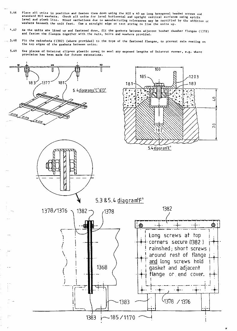
5.46 P l a c e a l l u n i t s i n p o s i t i o n and f a s t e n them down u s i n g the H 1 0 x 40 m long hexagonal headed screws and s t a n d a r d M l O washers. Check a11 u n i t s f o r l e v e l h o r i z o n t a l and u p r i g h t v e r t i c a l s u r f a c e s us ing s p i r i t l e v e l and plumb l i n e . Minor v a r i a t i o n a due t o manufac tur ing t o l e r a n c e s m y be r e c t i f i e d by t h e a d d i t i o n of washers benea th t h e u n i t f e e t . Uae a s t r a i g h t edge o r t a u t s t r iw t o l i n e t h e u n i t s up.
7 AS t h e u n i t s a r e l i n e d up and f a s t e n e d d o m , f i t t h e g a s k e t s between a d j a c e n t busbar chamber f l a n g e s (1378) and f a s t e n t h e f l a n g e s t o g e t h e r w i t h t h e n u t s , b o l t s and washers provided.
5.48 F i t t h e r a i n s h e d s (1382) (where provided) t o t h e t o p s of t h e f a s t e n e d f l a n g e s , t o prevent r a i n r e s t i n g on t h e t o p edges of t h e g a s k e t s between u n i t s .
5.49 Use p i e c e s of U n i s t r u t c l i p - u n p l a s t i c CoVeF, t o s e a 1 any exposed l e n g t h s of U n i s t r u t runner , e.g. s h e r e p r o v i s i o n has been made f o r f u t u r e e x t e n s i o n s .
I
/ Long screws a t top i . -+- corners secure (1382 ) 1-k . . ! rainshed; shor t screws i
- . around rest of flange i - -+ *t and Long screws hold I .
I - gasket and adjacent I . . +I flange o r . end cover. i-+-
I . . I . .-.-.-.-.-.-. I 1.- . .+:t-.*- , -6. .+ . -+
I 1
5 . 5 J o i n t i n g t h e Busbars
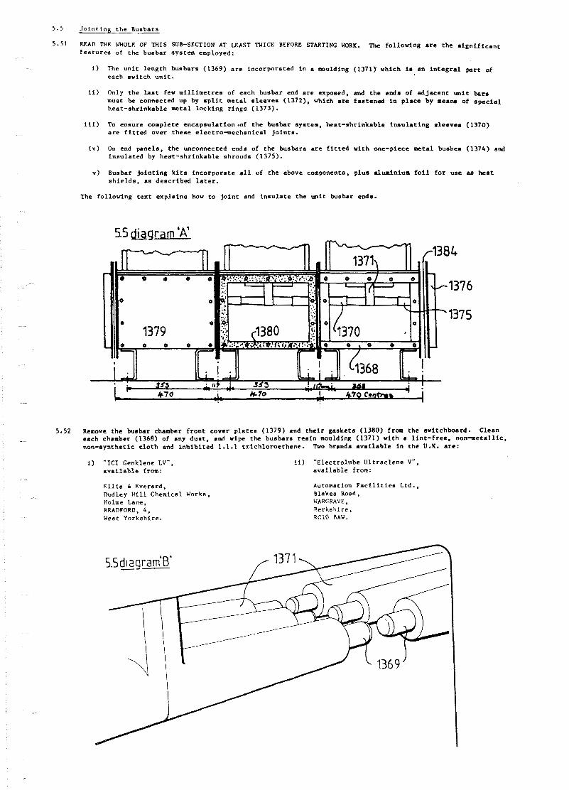
5 . 5 1 WAI, THE WHOLE OF M I S SUB-SECTION AT LEAST NICE BEFORE STARTING WORK. The f o l l o v i n g a r e t h e s i g n i f i c a n t f e a t u r e s of t h e busbar system employed:
1 ) The u n i t l e n g t h busbars (1369) a r e incorpora ted i n a moulding (1371). which is an i n t e g r a l p a r t of each swi tch u n i t .
i i ) Only the l a s t few m i l l i m e t r e e of each busbar end a r e exposed, and t h e ends of a d j a c e n t u n i t b a r s must be connected up by s p l i t me ta l s l e e v e s (1372). which a r e f a s t e n e d i n p l a c e by means of s p e c i a l hea t - shr inkab le meta l lock ing r i n g s (1373).
i i i ) To ensure complete e n c a p s u l a t i o n ~ o f t h e busbar system, hea t - shr inkab le i n s u l a t i n g s l e e v e s (1370) a r e f i t t e d over t h e s e e l e c t r o - m e c h a n i c a l j o i n t s .
i v ) On end pane l s , t h e unconnected ends of t h e busbars a r e f i t t e d wi th one-piece m e t a l bushes (1374) and i n s u l a t e d by hea t - shr inkab le sh rouds (1375).
V ) Busbar j o i n t i n g k i t s i n c o r p o r a t e a l l of the above components, p l u s a lua in ium f o i l f o r use ss h e a t s h i e l d s , a s d e s c r i b e d l a t e r .
The fo l lowing t e x t e x p l a i n s how t o j o i n t and i n s u l a t e t h e u n i t busbar ends.
55 &gram 'A'
5.52 Remove t h e busbar chamber f r o n t cover p l a t e s (1379) and t h e i r g a s k e t s (1380) from t h e switchboard. Clean each chamber (1368) of any d u s t , a d wipe t h e busbars r e s i n moulding (1371) wi th a l i n t - f r e e , n o n - m e t a l l i c , non-syn the t i c c l o t h and i n h i b i t e d 1.1.1 t r ~ i c h l o r o e t h e n c . TM brands a v a i l a b l e i n t h e U.K. a r e :
i ) " I C I Genklene LV", a v a i l a b l e from:
E l l i s 6 Everard, Dudley H i l l Chemical Works, Holme Lane. BRADFORD, 4 , Vest Yorkshire .
i f ) *Elec t ro lube U l t r s c l e n e V", a v s i l s b l e from:
Automation F a c i l i t i e s Ltd. , Blskes Road. WARGRAVE, Rerksh i re , RClO 8AU.

5.53 A t e ach i n t e r - p a n e l j o i n t , s l i p a n i n s u l a t i n g s l e e v e (1370) o v e r one of each p a i r of b u s b a r moulding l i m b s t o be j o i n e d , and r o l l o r f o l d t h e s l e e v e s back a t l e a s t 50 LQ ( 2 i n ) c l e a r of t h e b u s b a r m e t a l ends . Then, s l i p one me ta l l o c k i n g r i n g (1373) on e a c h busba r end and s l i d e i t beck a g a i n s t t h e end of t h e moulded i n s u l a t f on.
F i t t h e two h a l v e s of t h e s p l i t m e t a l s l e e v e (1372) t o each p a i r of busba r ends , and s e c u r e them l o o s e l y i n p l a c e by s l i d i n g t h e l o c k i n g r i n g s (1373) i n t o p o s i t i o n around t h e reduced d i a m e t e r end s e c t i o n s of t h e s l e e v e s .
Wrap t h e a l ~ m i n i u r n f o i l (13x5) a round t h e fo lded -hack s l e e v e s (1370) and t h e t v o s e t s of busba r m u l d i n g l imhs (1371) t o p r o t e c t them from t h e h e a t , and then use a gas t o r c h ( p r e f e r a b l y p ropane , bu t bu tane i s acceptable) t o h e a t up t h e l o c k i n g r i n g s (1373) and cause them t o s h r i n k and s o f a s t e n t h e me ta l s p l i t s l e e v e s (1372) In p l a c e . The t o r c h f l a m e shou ld be b l u e , "hard" and narrow so t h a t i t can Ix p r e c i s e l y d i r e c t e d a t t h e r i n g s and " s p i l l " a minimum of h e a t e l s e v h e r e . Apply t h e hea t e v e n l y around t h e c i r c u m f e r e n c e of each r i n g , and c o n t i n u e h e a t i n g i t u n t i l t h e g reen marker s p o t d a r k e n s t o show t h a t s u f f i c i e n t hea t has been abso rbed . Al low t h e r i n g s t o c o o l n a t u r a l l y , when i t vill be found t h a t t hey have sh runk t o form a t i g h t f i t on t h e s l e e v e s benea th .
Once a l l t h e r i n g s have been sh runk i n p l a c e and a l lowed t o c o o l , remove t h e a luminium f o i l (1385) from one i n s u l a t i n g s l e e v e (1370) . and r o l l t h e s l e e v e o u t t o i t s f u l l l e n g t h . P o s i t i o n t h e s l e e v e c e n t r a l l y o v e r t h e husha r j o i n t made o f f a s ahove , and s h r i n k - f i t i t i n t o p o s i t i o n a s f o l l o v s :
Using t h e gas t o r c h a g a i n , hut v i t h t h e f l a m e a d j u s t e d t o a . ' sof t" b lue v i t h a ye l low t i p , g e n t l y warm t h e i n s u l a t i n g s l e e v e (1370) . Keep t h e f l ame c o n t i n u a l l y moving ove r t h e s u r f a c e t o p reven t s c o r c h i n g and hot s p o t s . Heat t h e s l e e v e o v e r a l l b u t , a s i t b e g i n s t o s h r i n k , vork from t h e c e n t r e o u t v a r d s so a s t o a v o i d t r a p p i n g a i r i n t h e midd le . Xhen t h e s l e e v e is f u l l y sh runk , t he o u t e r s u r f a c e should be smooth and w r i n k l e - f r e e , and should f o l l o w t h e shape o f t h e components beneath i t .
Repeat f o r t h e i n s u l a t i n g s l e e v e s on a l l t h r e e phases a t each i n t e r - p a n e l busba r j o i n t l o c a t i o n .

5 . 5 7 On the o u t e r end of the hushar moulding (1371) of an end panel, push the non-shrinking metal bushes f u l l y home (1374) onto the ends of t h e busbars (1369). Put the i n s u l a t i n g "boots" (1375) i n p lace over then , push them on a s f a r a s they w i l l go and s h r i n k them i n t o pos i t ion as i n paragraph 5.56 above, t ak ing c a r e t o work from the closed t o t h e open ends of the "boots- to ensure a good f i t a d to expel excess a i r from t h e interior.

5 .58 W e n a l l of t h e i n t e r - p a n e l and end p a n e l h u s h a r e n d s ( 1 3 6 9 ) h a v e been d e a l t w i t h , c h a m b e r s ( 1 3 6 8 ) . c h e c k i n g t h a t no t o o l s o r m a t e r i a l s a r e l e f t i n them, t h e n F i t t t i e f r o n t c o v e r p l a t e g a s k e t s ( 1 3 8 0 ) and t h e p l a t e s t h e m s e l v e s ( 1 3 7 9 ) and r e p l a c e and f a s t e n t i g h t t h e i r n u t s 2nd w a s h e r s . S i m i l a r l y f i t and f a s t e n t h e d i s h e d b u s h a r c h a m h e r end c o v e r s ( 1 3 7 6 ) and g a s k e t s ( I 3 P L ) . F i t r a i n s t l e d s 1 1 3 8 2 ) t o t t i e t o p s of t h e end c o v e r f l a n g e < .
c l e a n o u t t h e b u s h a r
5 .59 C o n n e c t t h e un i : e a r t h b a r s o f ad i a c e n t u n i t s t o g e t h e r u s i n g t h e n ~ t s / s c r e w s i w a s h r r s prov i d e n and connet .c t h e w h o l e s w i t c h h o a r d e a r t h b a r s v s t e m t o t h e s u b s t a t i o n H . V . m e t a l w o r k e a r t h a c c o r d i n g t o l o c a l practice.
2.6 J o i n t i n g o f C a b l e s
T h e c a b l e j o i n t i n g ~ r o c e d u r e i s b a s i c a l l y t h e same a s t h a t employed on i n d o o r i m i t s : p l e a s e s e e s u b - s e c t i o n b . 7 o f t h i s m a n u a l .
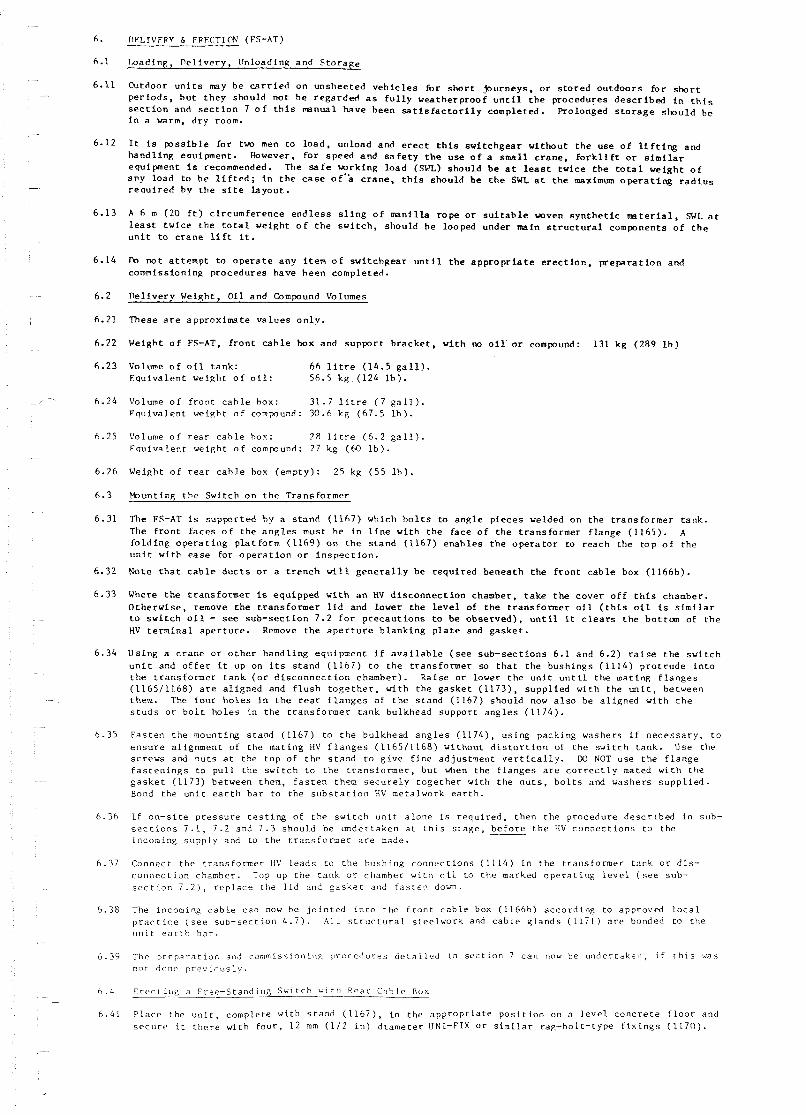
DFLIVFRv 6 FPFCTIPN (FS-AT)
l o a d i n g , D e l i v e r y , Un load ing a n d S t o r a g e
b t d o o r u n i t s m y b e c a r r i e d o n u n s h e e t e d v e h i c l e s for s h o r t + u r n e y s , o r s t o r e d o u t d o o r s f o r s h o r t p e r i o d s , h u t t h e y s h o u l d n o t h e r e g a r d e d a s f u l l y w e a t h e r p r o o f u n t i l t h e p r o c e d u r e s d e s c r i b e d i n t h i s s e c t i o n and s e c t i o n 7 o f t h i s manual h a v e h e e n s a t i s f a c t o r i l y c o m p l e t e d . P ro longed s t o r a g e s h o u l d b e i n a warm, d r y room.
I t is p o s s i b l e f o r two men t o l o a d , u n l o a d a n d erect t h i s s w i t c h g e a r w i t h o u t t h e u s e o f l i f t i n g and h a n d l i n g e o u i p n e n t . However, f o r s p e e d a n d s a f e t y t h e u s e o f a s m a l l c r a n e , f o r k l i f t o r s i m i l a r e q u i p m e n t i s recommended. The s a f e w r k i n g l o a d (SX) s h o u l d b e a t l e a s t t v i c e t h e t o t a l w e i g h t o f a n y l o a d t o h e l i f t e d ; i n t h e c a s e 0 f . k c r a n e , t h i s s h o u l d b e t h e SWL a t t h e maximum o p e r a t i n g r a d i u s r e a u i r e d b y t h e s i t e l a y o u t .
A 6 m (20 f t ) c i r c u m f e r e n c e e n d l e s s s l i n g o f m i n i l l a r o p e o r s u i t a b l e w v e n s y n t h e t i c r m t e r i a l , SWL a t l e a s t t w i c e t h e t o t a l w e i g h t o f t h e s w i t c h , s h o u l d h e looped u n d e r main s t r u c t u r a l componen t s o f t h e u n i t t o c r a n e l i f t i t .
Po n o t a t t e m p t t o o p e r a t e a n y i t e m o f s w i t c h g e a r u n t i l t h e a p p r o p r i a t e e r e c t i o n , p r e p a r a t i o n and c o m i s s i o n i n g p r o c e d u r e s h a v e h e e n c o m p l e t e d .
D e l i v e r y Weigh t , O i l a n d Compound Volumes
T h e s e a r e a p p r o x i m a t e v a l u e s o n l y .
Weigh t o f FS-AT, f r o n t c a h l e hox and s u p p o r t b r a c k e t , w i t h no o i l o r compound: 131 k g (289 l b )
Volume o f o i l t a n k : 6 6 l i t r e ( 1 4 . 5 g a l l ) . E q u i v a l e n t w e i g h t o f o i l : 56.5 k g . ( 1 2 4 l b ) .
Volume o f f r o n t c a h l e hox: 31.7 l i t r e ( 7 g a l l ) . F q u i v a l e n t w e i g h t o f c o m p u n d : 30.6 k g (67 .5 l h ) .
Volume o f r e a r c a h l e hox: 2 8 l i t r e ( 6 . 2 g a l l ) F q u i v a l e n t w e i g h t o f comwund : 27 k g (M) l b ) .
Weigh t o f r e a r c a h l e hox ( e m p t y ) : 25 kg ( 5 5 l h ) .
Y o u n t i n g t h e S w i t c h o n t h e T r a n s f o r m e r
The FS-AT i s s u p p o r t e d h y a s t a n d ( 1 1 6 7 ) wh ich h o l t s t o a n g l e p i e c e s welded on t h e t r a n s f o r m e r t a n k . The f r o n t f a c e s o f t h e a n g l e s mus t h e i n l i n e w i t h t h e f a c e o f t h e t r a n s f o r m e r f l a n g e ( 1 1 6 5 ) . A f o l d i n g o p e r a t i n g p l a t f o r m (1169) o n t h e s t a n d (1167) e n a h l e s t h e o p e r a t o r t o r e a c h t h e t o p o f t h e u n i t w i t h e a s e f o r o p e r a t i o n o r i n s p e c t i o n .
No te t h a t c a b l e d u c t s o r a t r e n c h w i l l g e n e r a l l y b e r e q u i r e d b e n e a t h t h e f r o n t c a b l e box (1166b)
Where t h e t r a n s f o r m e r is e q u i p p e d w i t h an HV d i s c o n n e c t i o n chamber , t a k e t h e c o v e r o f f t h i s chamber . O t h e r w i s e , remove t h e t r a n s f o r m e r l i d and lower t h e l e v e l of t h e t r a n s f o n n e r o i l ( t h i s o i l i s s i m i l a r t o s w i t c h o i l - s e e s u b - s e c t i o n 7 .2 f o r p r e c a u t i o n s t o be o b s e r v e d ) , u n t i l i t c l e a r s t h e b o t t a n of t h e HV t e r m i n a l a p e r t u r e . Remove t h e a p e r t u r e b l a n k i n g p l a t e and g a s k e t .
U s i n g a c r a n e o r o t h e r h a n d l i n g e q u i p m e n t i f a v a i l a b l e ( s e e s u b - s e c t i o n s 6 .1 a n d 6 .2) r a i s e t h e s w i t c h u n i t and o f f e r i t up on i ts s t a n d ( 1 1 6 7 ) t o t h e t r a n s f o r m e r so t h a t t h e b u s h i n g s ( 1 1 1 4 ) p r o t r u d e i n t o t h e t r a n s f o r m e r t a n k ( o r d i s c o n n e c t i o n chamber ) . R a i s e o r l ower t h e u n i t u n t i l t h e m a t i n g f l a n g e s ( 1 1 6 5 / 1 1 6 8 ) a r e a l i g n e d and f l u s h t o g e t h e r , w i t h t h e g a s k e t ( 1 1 7 3 ) , s u p p l i e d w i t h t h e u n i t , b e t w e e n them. The f o u r h o l e s i n t h e r e a r f l a n g e s o f t h e s t a n d (1167) s h o u l d now a l s o b e a l i g n e d w i t h t h e s t u d s o r b o l t h o l e s i n t h e t r a n s f o r m e r t a n k b u l k h e a d s u p p o r t a n g l e s ( 1 1 7 4 ) .
F a s t e n t h e moun t ing s t a n d (1167) t o t h e b u l k h e a d a n g l e s (11741, u s i n g p a c k i n g w a s h e r s i f n e c e s s a r y , t o e n s u r e a l i g n m e n t o f t h e m a t i n g HV f l a n g e s (116511168) w i t h o u t d i s t o r t i o n of t h e s w i t c h t a n k . Use t h e s c r e w s and n u t s a t t h e t o p o f t h e s t a n d t o g i v e f i n e a d j u s t m e n t v e r t i c a l l y . D3 NOT u s e t h e f l a n g e f a s t e n i n g s t o p u l l t h e s w i t c h t o t h e t r a n s f o r m e r , b u t when t h e f l a n g e s a r e c o r r e c t l y mated w i t h t h e g a s k e t (1173) be tween them, f a s t e n them s e c u r e l y t o g e t h e r w i t h t h e n u t s , b o l t s and w a s h e r s s u p p l i e d . Bond t h e u n i t e a r t h b a r t o t h e s u b s t a t i o n HV me ta lwork e a r t h .
I f o n - s i t e p r e s s u r e t e s t i n g o f t h e s w i t c h u n i t a l o n e is r e q u i r e d , t h e n t h e p r o c e d u r e d e s c r i b e d i n sub - s e c t i o n s 7 . 1 , 7 .2 and 7 . 3 s h o u l d be u n d e r t a k e n a t t h i s s t a g e , b e f o r e t h e H V c o n n e c t i o n s t o t h e incoming s u p p l y and t o t h e t r a n s f o r m e r a r e made.
C o n n e c t t h e t r a n s f o r m e r H V l e a d s t o t h e b u s h i n g c o n n e c t i o n s ( 1 1 1 4 ) i n t h e t r a n s f o r m e r t a n k o r d i s - c o n n e c t i o n chamber . Top up t h e t a n k o r chamber w i t h o i l t o t h e marked o p e r a t i n g l e v e l ( s e e sub- s e c t i o n 7 . 2 ) , r e p l a c e t h e l i d and g a s k e t and f a s t e n dokm.
The incoming c a b l e c a n now be j o i n t e d i n t o t h e F ron t c a b l e box (1166b) a c c o r d i n g t o approved l o c a l p r a c t i c e ( s e e s u b - s e c t i o n 4 . 7 ) . A l l s t r u c t u r a l s t e e l w o r k and c a b l e g l a n d s ( 1 1 7 1 ) a r e bonded t o t h e u n i t e a r t h b a r .
The p r e p a r a t i o n and c o n m i s s i o n i n p n r o c e d u r e s d e t a i i e d in s e c t i o n 7 c a n now be u n d e r t a k e n , i f Ch i s 'was n o t done p r e v i o u s l y .
E r e c t i n g a F r c r - S t a n d i n g S w i t c h w i t h R e a r C a b l e Rox
P l a c e t h e u n i t , c o m p l e t e w i t h s t a n d ( l l 6 7 ) , i n t h e a p p r o p r i a t e p o s i t Lon on a l e v e l c o n c r e t e f l o o r and s e c u r e i t t h e r e w i t h f o u r , 1 2 mm (112 i n ) d i a m e t e r UNI-FIX O r s i m i l a r rdg -bo l t - t ype f i x i n g s ( 1 1 7 0 ) .
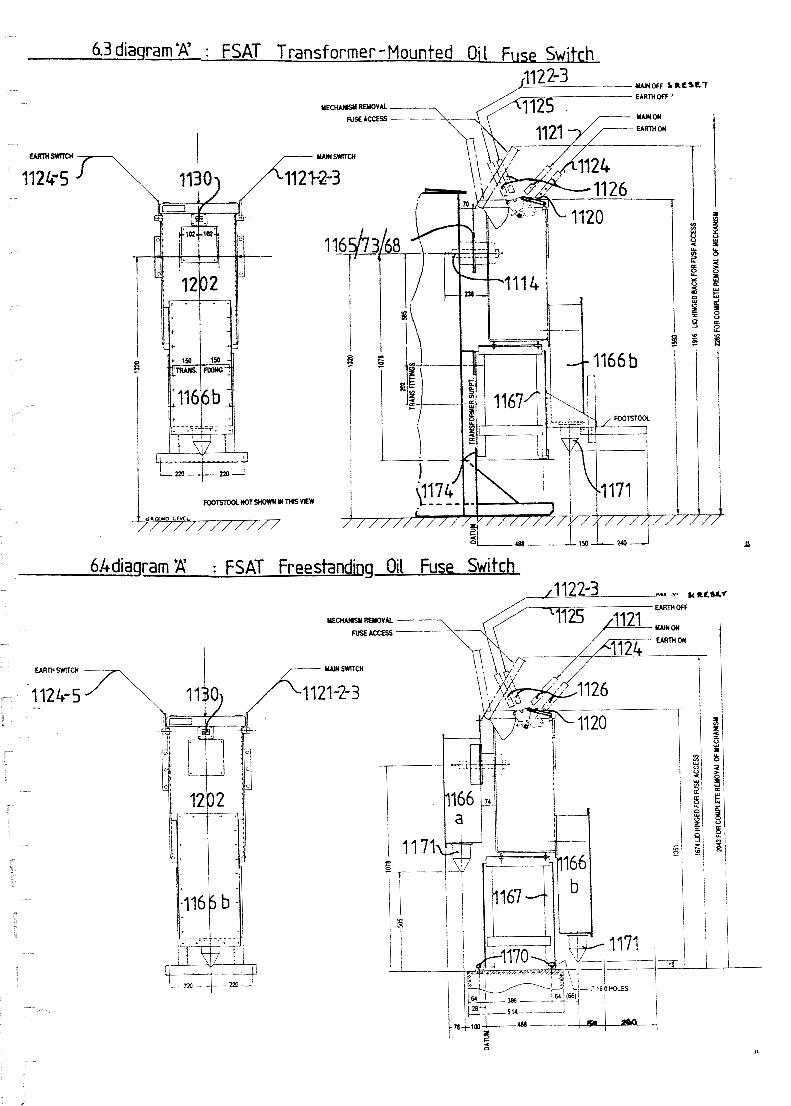
6.3 diagram 'A' : FSAT Transformer -Mounted Oi l Fllsp Switch
6bdiaqram 'A' : FSAT Freestanding Oil FUSP Switch

6.42 Note t h a t t h e two c a b l e boxes (1166a, b) r e q u i r e c a b l e d u c t s o r t r e n c h e s benea th them t o accommodate t h e c a b l e s .
6 . 4 1 Bond t h e u n i t e a r t h bar t o t h e s u b s t a t i o n HV metalwork e a r t h .
6.44 I f o n - s i t e p r e s s u r e t e s t i n g of t h e r i n g main u n i t a l o n e is r e q u i r e d , t h e n t h e procedures d e s c r i b e d i n s u b - s e c t i o n s 7.1, 7 . 2 and 7 . 3 should be under taken a t t h i s s t a g e , b e f o r e t h e HV c a b l e c o n n e c t i o n s t o t h e incoming supply and t o t h e t r a n s f o r m e r a r e m d e .
6.45 The f r o n t and r e a r c a b l e s can now be j o i n t e d i n t o t h e i r r e s p e c t i v e boxes (1166a. b ) a c c o r d i n g t o approved l o c a l p r a c t i c e ( s e e s u b - s e c t i o n 4.7). A l l s t r u c t u r a l metalwork and c a b l e g l a n d s (1171) a r e bonded t o t h e u n i t e a r t h bar . . ,
6.46 The p r e p a r a t i o n and commissioning procedures i n s e c t i o n 7 c a n nov be under taken i f t h i s v a s n o t done p r e v i o u s l y .
6 . 5 J o i n t i n g of Cables
The c a b l e j o i n t i n g procedure is b a s i c a l l y t h e same as t h a t employed on indoor u n i t s : p l e a s e s e e sub- s e c t i o n s 4.7 and 6 . 2 of t h i s manual.
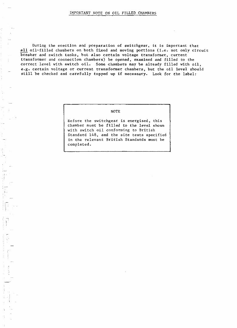
IMPORTANT NOTE ON OIL FILLED CHAMBERS
During t h e e r e c t i o n and p r e p a r a t i o n of swi tchgear , i t is important t h a t a l l o i l - f i l l e d chambers on b o t h £ b e d and moving p o r t i o n s ( i . e . n o t o n l y c i r c u i t - b r e a k e r and swi tch t a n k s , b u t a l s o c e r t a i n v o l t a g e t rans former , c u r r e n t t r ans former and connect i o n chambers) be opened, examined and f i l l e d t o t h e c o r r e c t l e v e l wi th s w i t c h o i l . Some chambers may be a l r e a d y f i l l e d wi th o i l , e.g. c e r t a i n v o l t a g e o r c u r r e n t t r a n s f o r m e r chambers, bu t the o i l l e v e l should s t i l l b e checked and c a r e f u l l y topped up i f necessa ry . Look f o r t h e l a b e l :
I NOTE
B e f o r e t h e s w i t c h g e a r i s e n e r g i s e d , t h i s chamber must be f i l l e d t o t h e l e v e l shown w i t h s w i t c h o i l conforming t o B r i t i s h S tandard 148, and t h e s i t e t e s t s s p e c i f i e d i n t h e r e l e v a n t B r i t i s h S tandards must be completed.

NOTE: Do not opera te e i t h e r s v i t c h un le s s t h e cover (1205) i s secure ly fas tened down. - Prepara t ion of Tank 6 Mechanisms
WITH BUSBARS ( I F ANY) AND OUTGOING CIRCUIT CONNECTIONS (1114, 1166a, 1166b) DEjrD, remove a l l packing ma te r i a l s , wipe down the o u t s i d e of t h e t a n k (1202) and, v i t h opera t ing handle s t u b s e t t o t h e RESET (1123) and EARTH OFF (1125) p o s i t i o n s a s i nd i ca t ed by OFF i n the tank window (1130), un fa s t en t h e main cover r e t a in ing sc revs and r a i s e t h e cover (1205). The spring-loaded mechanism mainframe (1108) v i l l r i s e with i t . A c a r r i a g e r e t a i n i n g c l i p (1127) on the l e f t hand mainframe member w i l l sv ing out t o support the frame and l i d .
I I
Slacken off the f r o n t f a s t e n e r on t h e r o l l e r bracket (1159) on the underside of t he cover (1205) and s l i d e the bracket c l e a r of t h e r o l l e r (1128) on the mainframe. The mechanism mainframe can now be l i f t e d out of t he tank f o r d e t a i l e d examination.
Wipe out the tank (1202) wi th a c l e a n , d ry , l i n t - f r e e , non-meta l l ic c lo th . Check f o r fo re ign bodies i n the tank bottom. Examine a l l bea r ings , c o n t a c t s and the mechanisms on the mainframe (1108) f o r loose components o r f a s t e n i n g s .
Hake sure t ha t the s v i t c h handle s t u b s a r e s t i l l set t o EARTH OFF (1125) and RESET (1123) and r ep l ace the mechanism mainframe (1108) i n its- guides i n t h e tank.
Check t h a t t he c o r r e c t f u s e s (311) a r e f i t t e d . I f not , r a i s e t he mechanism t r i p bar (1112), r a i s e t he hinged upper contac t fu se r e t a i n i n g c l i p s (1131) and remove the fuses t h a t have been suppl ied ( i f any). Check the fu ses f o r damage, then p l ace them i n t h e i r lower fu se contac t cups (1110) v i t h s t r i k e r pin ends upwards ( s e e markings on fuse bodies). Twist a d press each fuse down f i rmly t o ensure t h a t i t i s s ea t ed s a t i s f a c t o r i l y , and p re s s down the hinged c l i p s (1131) around t h e tops of t he fuses . Lover the t r i p bar (1112) ac ros s t he tops of the fuses .
F i l l the tank (1202) t o t he marked l e v e l w i th switch o i l a s described i n s u b s e c t i o n 5.2. Pour o i l over the mechanisms mounted i n t he mainframe (1108). Note t he o i l l e v e l l a b e l on the fu se c a r r i e r : " O i l t o be l e v e l v i t h t h i s p l a t e w i th nechanism on hold up ca tch and fuses f i t t e d " .
71 diagram 'A' -

7-17 Re-engage t h e t o p r o l l e r (1128) w i t h t h e r o l l e r b r a c k e t (1159) on t h e unders ide of t h e cover (1205) and s l i d e and f a s t e n t h e b r a c k e t i n t o i t s o r i g i n a l p o s i t i o n . Close and f a s t e n down t h e cover a f t e r checking t h a t i t s g a s k e t i s s e c u r e and i n good c o n d i t i o n . Check t h e o p e r a t i o n of t h e handles and i n t e r l o c k s ( a s f a r a s p o s s i b l e ) by r e f e r e n c e t o s e c t i o n 8 of t h i s manual.
7.2 O i l F i l l i n g of Swi tchgear
7.21 Swi tchgear is normal ly d e s p a t c h e d w i t h o u t o i l and vhen t h e equipment is f i l l e d on s i t e i t i s n e c e s s a r y t o observe c e r t a i n p r e c a u t i o n s t o e n s u r e s a t i s f a c t o r y o p e r a t i o n . These p r e c a u t i o n s a r e a l s o a p p l i c a b l e t o t h e h a n d l i n g of t r a n s f o r m f r o i l .
7.22 The o i l must be of t h e c o r r e c t g r a d e ( n o r m a l l y B30 f o r s w i t c h g e a r ) , should p r e f e r a b l y be used from s e a l e d drums, and must have a n e l e c t r i c a l s t r e n g t h of n o t l e s s than t h a t s p e c i f i e d by BS 148. Clean o i l must not be s t o r e d i n drums which have h e l d d i r t y o i l .
7.23 A l l pumps, p i p e s and o t h e r f i l l i n g u t e n s i l s must be c l e a n and dry and must have a tempera ture s i m i l a r t o t h a t of t h e o i l and s v i t c h g e a r . S e p a r a t e equipment should be used f o r c l e a n and d i r t y o i l s .
7.24 Rubber t u b i n g o r any o t h e r m a t e r i a l which is s o l u b l e i n o i l should no t be used.
7.25 A l l components of t h e s w i t c h g e a r which a r e t o be immersed i n t h e o i l must be thoroughly c leaned w i t h l i n t - f r e e , non-meta l l i c c l o t h s . Do n o t u s e c l e a n i n g s o l v e n t s , which might contamina te t h e o i l .
7.26 To avoid c o n d e n s a t i o n , o i l and s w i t c h g e a r s h o u l d be a t l e a s t a s warm as t h e sur rounding a i r , and i n a d d i t i o n t h e s w i t c h g e a r should be d r y ; t h i s c o n d i t i o n can be ob ta ined by a l lowing t h e v a w a i r t o c i r c u l a t e through t h e s w i t c h g e a r w i t h t h e tanks open. A l l p a r t s i n s i d e t h e chamber o r t ank dl1 then q u i c k l y a t t a i n a tmospher ic t e m p e r a t u r e . I f t h i s method cannot be used. a c h i e v e t h e same r e s u l t by p l a c i n g bags of s i l i c a g e l d e s s i c a n t i n t h e charpbers f o r a per iod of some hours . Care must , however, be taken t o e n s u r e t h a t a l l of t h e s e bags a r e removed b e f o r e f i l l i n g commences. When t h e equipment i s comple te ly d r y , no m o i s t u r e v i l l a p p e a r on a m i r r o r he ld i n s i d e t h e chamber.
7.27 The c o r r e c t o i l l e v e l is marked on t h e i n s i d e of t h e o i l swi tch and f u s e swi tch chambers and on t h e o u t s i d e of c i r c u i t b r e a k e r and v o l t a g e t r a n s f o r m e r tanks .
7.28 A f t e r f i l l i n g it is a d v i s a b l e t o o p e r a t e t h e s w i t c h g e a r s e v e r a l t imes b e f o r e apply ing v o l t a g e i n o r d e r t o r e l e a s e any a i r which may be t r a p p e d .
7.29 WARNING: No naked l i g h t should be p e r m i t t e d i n t h e v i c i n i t y of open tanks o r i n o t h e r s i t u a t i o n s where s v i t c h o i l is d i r e c t l y exposed t o t h e a tmosphere ( t h i s p r e c a u t i o n is p a r t i c u l a r l y impor tan t d u r i n g p o s t - f a u l t maintenance).
7.3 High Vol tage T e s t s
7.31 The a p p l i c a t i o n of a h i g h v o l t a g e p r e s s u r e t e s t is o f t e n c a l l e d f o r , f o r example, b e f o r e commissioning o r d u r i n g maintenance of m e t a l c l a d s w i t c h g e a r , a c c o r d i n g t o l o c a l r e g u l a t i o n s .
BS.5227:1975 s p e c i f i e s t h e f o l l o w i n g one minute power f requency t e s t v o l t a g e s f o r such s i t e t e s t s :
I M A I N CIRCUIT I M A I N CIRCUIT I 1 RATED VOLTAGE I SITE TEST VOLTAGE I I I 1 kV I kV \ I 3.6 I 8.6 I I 7.2 1 15.2 I I 12.0 I 24.0 I I 17.5 1 32 .O I
A u x i l i a r y c i r c u i t s : 2.0kV
7.32 I t i s p r e f e r a b l e t o r e p l a c e t h e f u s e s by c o n d u c t i n g l i n k s i f these a r e a v a i l a b l e , but t h e f u s e s may be l e f t i n p lace o t h e r v i s e .
The f i r s t t e s t should be a p p l i e d t h u s :
( a ) a l l phases t o e a r t h w i t h s w i t c h c l o s e d ;
( b ) between phases wi th s w i t c h c l o s e d ;
( c ) a c r o s s t h e break of t h e open s w i t c h .
7.33 I f t h e equipment is not l a r g e enough t o produce t h e c o r r e c t t e s t v o l t a g e , a prolonged t e s t a t reduced v o l t a g e i n accordance w i t h t h e t a b l e below may be a p p l i e d .
I POWER-FREQUENCY VOLTAGE TESTS I I FOR DURATIONS EXCEEDING ONE MINLlTE 1 1 (AFTER ERECTION ON SITE) 1 I D u r a t i o n of t e s t 1 P e r c e n t a ~ e of I - 1 I one-minute t es t I 1 I v o l t a g e accord ing 1 I Minutes I t o paragraph 7.31 1 I I I

7.34 D.C. Testing:
The use of D.C. t e s t s e t s f o r cab le t e s t i n g i s now widespread and the use of t h i s equipment f o r t he pressure t e s t i o g of switchgear is o f t e n convenient- The case aga ins t D.C. t e s t i n g is t h a t t h e i n s u l a t i o n i s not s t r e s sed i n the same manner a s when an A.C. vol tage , f o r which i t m s design&, is appl ied , but experience has not i nd ica t ed t h a t i n i t i a t i o n of breakdown is more l i k e l y with D.C. than v i t h A.C. In the event of a D.C. v o l t a g e t e s t being applied to the switchgear. the values must be i n accordance with the t a b l e below. the du ra t ion of t e s t t o be 15 minutes.
I D.C. TEST VOLTAGES I I Rated Voltage 1 S i t e Test Voltage I I I I
7.35 I f high vol tage t e s t i n g of the connecting cab le o r cab le s is required once they have been jo inted i n t o the svi tchgear , B.S.5227 s p e c i f i e s the following d.c. values:
1 RATED VOLTAGE 1 *BETWEEN PHASES / BETWEEN ALL PHASES I I OF SWITCKEAR I OF BELTED CABLES 1 AND EARTH 1 I I I I
I 1 I I *With midpoint of t e s t supply earthed.
7.4 Paintwotk
A l l components a re given a N g h q u a l i t y p ro tec t ive f i n i s h before leaving the vorks, but the paintwork m y be dmaged during t r a n s p o r t , e r e c t i o n o r service . Any sc ra t ches o r chipped por t ions of t h e paintwork should be touched up immediately they a r e not iced, otherwise the metalwork may rus t .
Su i t ab le touch up paint is a v a i l a b l e from Yorkshire Switchgear, o r i t may be obtained from any reputable manufacturer. The s p e c i f i c a t i o n is:-
"Glossy Synthet ic A i r Drying Enamel f o r Outdoor Use". Quote the appropr ia te colour references :
Colour Colour No. (BS 381C: 1948)
Dark admiralty Grey 632
or such other colour a s may have been s p e c i f i e d f o r a p a r t i c u l a r i n s t a l l a t i o n .

ROUTINE FUSE SWITCH OPERATION
NOTE: D o n o t o p e r a t e e i t h e r s w i t c h u n l e s s t h e c o v e r (1205) i s s e c u r e l y f a s t e n e d down. - TO C l o s e t h e Main F u s e S w i t c h t o ON
Note t h a t t h e i n d i c a t i o n i n t h e t a n k vfndow (1130) i s OFF.
Unlock t h e main s w i t c h h a n d l e s t u b ( 1 1 2 2 ) f rom i t s p a d l o c k p o i n t (1119) a t t h e r i g h t hand s i d e o f t h e c o v e r (1205) . F i t t h e r e m o v a b l e o p e r a t i n g h a n d l e (1126) t o t h e s t u b (1122) .
Move t h e o p e r a t i n g h a n d l e (1126) backwar+ as f a r a s it w i l l go, t o t h e RESET p o s i t i o n (1123) . t o e n g a g e t h e c l o s i n g mechanism. Remove t h e h a n d l e and r e - l o c a t e i t f o r t h e fo rward s t r o k ' e o n t h e same s t u b .
Move t h e o p e r a t i n g h a n d l e ( 1 1 2 6 ) f i r m l y f o r w a r d s t o t h e ON p o s i t i o n (1121) t o c l o s e t h e ma in s v i t c h (1101 /1102) . The i n d i c a t i o n i n t h e window (1130) w i l l change t o ON.
Remove t h e o p e r a t i n g h a n d l e (1126) . P a d l o c k t h e h a n d l e s t u b (1121) t o i t s p a d l o c k p o i n t (1119) u n l e s s a c c e s s f o r emergency t r i p p i n g is r e q u i r e d .
To T r i p t h e Main F u s e S w i t c h t o OFF
Note t h a t t h e i n d i c a t i o n i n t h e t a n k window (1130) i s ON.
Unlock t h e main s w i t c h h a n d l e s t u b (1121) f r o m i t s p a d l o c k p o i n t (1119) a t t h e r i g h t hand s i d e o f t h e c o v e r (1205) . F i t t h e r e m o v a b l e o p e r a t i r g h a n d l e (1126) t o t h e s t u b (1121) .
Hove t h e o p e r a t i n g h a n d l e ( 1 1 2 6 ) b a c k w a r d s t o t h e OFF p o s i t i o n (1122) . b u t n o t a s f a r as t h e RESET p o s i t i o n (1123) . At t h e OFF p o s i t i o n , you w i l l h e a r t h e mechanism t r i p and s e e t h e t a n k window i n d i c a t i o n (1130) c h a n g e t o OFF.
Remove t h e o p e r a t i n g h a n d l e ( 1 1 2 6 ) . P a d l o c k t h e s t u b (1121) (1123 i f r e s e t ) i n p o s i t i o n .
Fuse O p e r a t i o n on F a u l t
I f any f u s e (311) o p e r a t e s o n f a u l t o r o v e r l o a d , a s t r i k e r p i n is e j e c t e d from i t s t o p end. T h i s r a i s e s t h e main s w i t c h mechanism t r i p b a r (1112) and moves t h e t r i p c a t c h (1144) t o t r i p t h e f u s e s w i t c h (1101 , 1102 , 1 1 0 5 ) a n d p r e v e n t s t h e s w i t c h b e i n g s u c c e s s f u l l y r e c l o s e d , as t h e mechanism c a n n o t l a t c h i n w i t h t h e t r i p b a r r a i s e d . However, t h e r e i s n o t h i n g t o p r e v e n t a momentary c l o s u r e o f t h e c o n t a c t s , s o DO NOT o p e r a t e t h e mechanism t o ON u n t i l t h e f u s e s have been r e p l a c e d . A l l t h r e e f u s e s must be r e p l a c e d , e v e n t h o u g h t h e y may n o t a l l h a v e blown: i n t e r n a l damage may n o t show.
See a l s o s u b - s e c t i o n 9 . 4
To E a r t h t h e T r a n s f o r m e r C i r c u i t
Note t h a t t h e i n d i c a t i o n i n t h e t a n k v indow (1130) i s OFF. E n s u r e t h a t t h e o u t g o i n g t r a n s f o r m e r c i r c u i t is i s o l a t e d and l o c k e d o f f f rom a n y a l t e r n a t i v e s u p p l y a t t h e r emote end ( e - g . v i a t h e medium) v o l t a g e c i r c u i t s f e d by t h e t r a n s f o r m e r ) o r any i n t e r m e d i a t e p o i n t (e.g. f e e d s v i a tee j o i n t s o n t h e o u t g o i n g c a b l e of a f r e e - s t a n d i n g f u s e s w i t c h ) .
Unlock t h e h inged MOVE BEFORE EARTHING p a d l o c k a b l e l i n k (1120) a t t h e l e f t hand s i d e of t h e c o v e r ( 1 2 0 5 ) and move i t c l e a r o f t h e e a r t h s w i t c h h a n d l e s t u b (1125) . F i t t h e r emovab le o p e r a t i n g h a n d l e ( 1 1 2 6 ) t o t h e s t u b .
Move t h e o p e r a t i n g h a n d l e ( 1 1 2 6 ) f i r m l y f o r w a r d s a s f a r a s i c w i l l go , t o t h e EARTH ON p o s i t i o n ( 1 1 2 4 ) t o e a r t h t h e o u t g o i n g c i r c u i t ( 1 1 9 7 , 1 1 0 4 , 1 1 1 4 ) . The i n d i c a t i o n i n t h e t a n k window ( 1 1 3 0 ) w i l l change t o EARTH ON.
Because of t h e d e s i g n of c o l l a p s i b l e h a n d l e employed on t h e e a r t h s w i t c h (1124 , 1 1 2 6 ) i t is i m p o s s i b l e f o r an o p e r a t o r t o i m m e d i a t e l y r e -open a c l o s e d e a r t h s w i t c h ; t h e o p e r a t i n g h a n d l e (1126) mus t be removed and r e l o c a t e d f rom t h e r e a r t o t h e f r o n t p o s i t i o n . Thus, shou ld an e a r t h be i n a d v e r t e n t l y a p p l i e d t o a LIVE c i r c u i t , t h e o p e r a t o r c a n n o t i n s t i n c t i v e l y re-open t h e n o n - f a u l t - b r e a k i n g e a r t h s w i t c h a t once , w i t h t h e p o s s i b i l i t y of b r e a k i n g t h e f a u l t c u r r e n t , b e f o r e remote p r o t e c t i o n h a s had t i n e t o o p e r a t e .
On c o m p l e t i o n of t h e e a r t h i n g o p e r a t i o n , remove t h e o p e r a t i n g h a n d l e ( 1 1 2 6 ) . P i v o t t h e p a d l o c k a b l e MOLT BEFORE EARTHING l i n k ( 1 1 2 0 ) back t o t h e s t u b (1124) and padlock i t i n p o s i t i o n .
To Remove t h e E a r t h from t h e T r a n s f o r m e r C i r c u i t
Note t h a t t h e i n d i c a t i o n i n t h e t a n k v indow ( 1 1 3 0 ) is EARTH OY.
L'nlock t h e h inged EIOVE BEFORE EARTHING p a d l o c k a b l e l i n k ( 1 1 2 0 ) a t t h e l e f t hand s i d e of t h e c o v e r (1205) and move i t c l e a r of t h e e a r t h s w i t c h h a n d l e s t u b (1124) . F i t t h e removable o p e r a t i n g h a n d l e (1126) t o t h e sci ib-
8 - 5 3 :love t h e o p e r a t i n g h a n d l e ( 1 1 2 6 ) i i r n l l ; but smooth ly backwards a s f a r a s i t w i l l go t o t h e EARTH OFF p o s i t i o n ( ! 1 ? 5 ) t o remove t h e e a r t h f rom t h e o u t g o i n g c i r c u i t . The i n d i c a t i o n i n t h e t a n k window (1130) w i l l change t o OFF.
8 . 5 1 On c o n p l e ~ i o n o i t h e o p e n i n g o p e r a t i o n , r imove t h e o p e r a t i n g hand le ( 1 1 2 6 ) . P ivo t t h e p a d l o c k a b l e MOVE BEFORE E A R T H I N G l i n k ( 1 1 2 0 ) hack t o t h e s t u b (1125) and padlock i t i n p o s i t i o n .

Section 8,diagram 'A'
E A R T H S W 1 T C . h
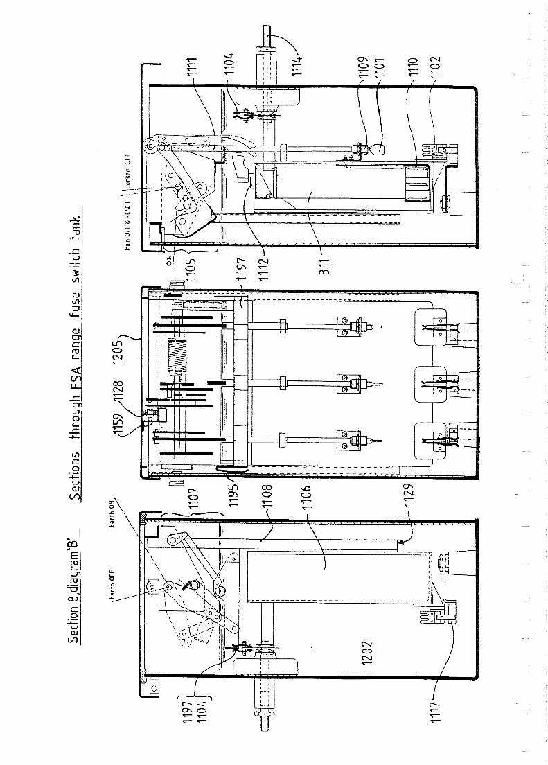
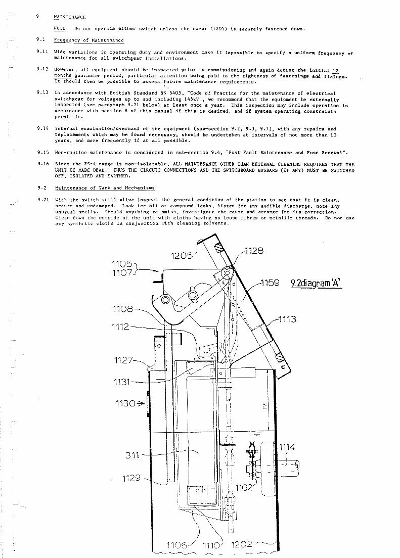
MAINTENANCE
NOTE: Do not o p e r a t e e i t h e r s w i t c h u n l e s s t h e cover (1205) is s e c u r e l y fas tened down. - Frequency of Maintenance
Wide v a r i a t i o n s i n o p e r a t i n g d u t y and environment make i t impossible t o s p e c i f y d uniform f requency of maintenance f o r a l l s w i t c h g e a r i n s t a l l a t i o n s .
However, a l l equipment should be i n s p e c t e d p r i o r t o commissioning and a g a i n d u r i n g t h e i n i t i a l 1 2 months g u a r a n t e e p e r i o d , p a r t i c u l a r a t t e n t i o n be ing paid t o t h e t i g h t n e s s of f a s t e n i n g s and f i x G a . I t should then be p o s s i b l e t o a s s e s s f u t u r e maintenance requirements.
I n accordance wi th B r i t i s h S t a n d a r d BS 5405, "Code o f P r a c t i c e f o r t h e maintenance of e l e c t r i c a l s w i t c h g e a r f o r v o l t a g e s up t o and i n c l u d i n g 145kV", we recommend t h a t t h e equipment be e x t e r n a l l y inspec ted ( s e e paragraph 9.21 below) a t l e a s t once a year . This i n s p e c t i o n may i n c l u d e o p e r a t i o n i n accordance with s e c t i o n 8 of t h i s manual i f t h i s i s d e s i r e d , and i f system o p e r a t i n g c o n s t r a i n t s permit i t .
I n t e r n a l examina t ion /overhaul of t h e equipment ( sub-sec t ion 9 .2 , 9.3, 9 .7) , wi th any r e p a i r s and replacements which may be found n e c e s s a r y , should be undertaken a t i n t e r v a l s of no t more t h a n 10 y e a r s , and more f r e q u e n t l y i f a t a l l p o s s i b l e .
Non-routine maintenance is c o n s i d e r e d i n sub-sec t ion 9.4, "Post F a u l t Maintenance and Fuse Renewal".
S ince t h e FS-A range is n o n - i s o l a t a b l e , ALL MAINTENANCE OTHER THAN EXTERNAL CLEANING REQUIRES THAT THE UNIT BE MADE DEAD. THUS THE CIRCUIT CONNECTIONS AND THE SWITCHBOARD BUSBARS ( I F ANY) MUST BE SWITCHED OFF, ISOLATED AND EARTHED.
Maintenance of Tank and Mechanisms
With t h e swi tch s t i l l a l i v e i n s p e c t t h e g e n e r a l c o n d i t i o n of the s t a t i o n t o see t h a t it is c l e a n , secure and undamaged- Look f o r o i l o r compound l e a k s , l i s t e n f o r any a u d i b l e d i s c h a r g e , n o t e any unusual smel l s . Should a n y t h i n g be a m i s s , i n v e s t i g a t e t h e cause and a r range f o r its c o r r e c t i o n . Clean down the o u t s i d e of t h e u n i t w i t h c l o t h s having no loose f i b r e s o r m e t a l l i c t h r e a d s . Do not u s e any s y n t h t t i c c l o t h s i n c o n j u n c t i o n w i t h c l e a n i n g s o l v e n t s .
9.2di - agram 'A'
13

WITH THE SWITCHBOARD BUSBARS ( I F AKY) AND OUTGOING (1114) CIRCUIT CONNECTIONS MADE DEAD, LOCKED OFF AT ALL POSSIBLE POINTS OF SUPPLY AND EFFECTIVELY EAR'HED, s e t t h e e a r t h swi tch t o EARTH OFF and t h e main s w i t c h t o OFF and RESET ( s e e s e c t i o n 8 ) p o s i t i o n s a s i n d i c a t e d by OFF i n t h e tank vindow (1130). Unfas ten t h e main c o v e r r e t a i n i n g screws and r a i s e t h e cover (1205). The s p r i n g loaded mechanism mainframe (1108) w i l l r i s e d t h i t . A c a r r i a g e r e t a i n i n g c l i p (1127) on t h e l e f t hand mainframe member w i l l swing o u t t o s u p p o r t t h e frame and l i d . Slacken o f f t h e c a p t i v e f a s t e n e r s on t h e r o l l e r b r a c k e t (1159) on t h e u n d e r s i d e of t h e cover (1205) and s l i d e t h e bracke t c l e a r of t h e r o l l e r (1128) on t h e mainframe. The c o v e r can now be swung back, c l e a r of t h e tank top , and t h e mechanism mainframe (1108) c a n be l i f t e d o u t .
WARNING: NO NAKED LIGHT SHOULD BE PERMITTED I N THE VICINITY OF OPEN TANKS OR DRUMS OF WITCH OIL.
I n s p e c t t h e f u s e l i n k s (311) f o r s i g n s of mechanical o r thermal damage, and r e p l a c e any which show such s i g n s . Find and c o r r e c t t h e c a u s e of any such f u s e damage (e.g. l o o s e c o n t a c t s i n t h e f u s e c a r r i e r ) . Examine t h e s w i t c h mechanism (1105, 1107) f o r s i g n s of wear, l o o s e f a s t e n i n g s , b u r n t o r s p l i t i n s u l a t i o n e t c . , and t i g h t e n o r r e p l a c e as necessary . Inspec t a l l c o n t a c t s on t h e mainframe (1108) and f u s e c a r r i a g e (1106) f o r s i g n s of burning o r wear. Smooth v i t h a f i l e o r r e p l a c e any v h i c h r e q u i r e a t t e n t i o n .
Sample and t e s t t h e s w i t c h o i l a s d e s c r i b e d i n sub-sec t ion 9 . 3 . I f t h e o i l i s c l e a r , it w i l l be p o s s i b l e t o c a r r y o u t t h e r e s t of t h e r o u t i n e i n s p e c t i o n w i t h t h e o i l s t i l l i n t h e t a n k (1202). Should t h e o i l be murky, o r f a i l any of t h e p r e s c r i b e d t e s t s , o r should i n s p e c t i o n show t h a t maintenance work w i t h i n t h e t a n k i s r e q u i r e d , t h e n t h e tank must be emptied and l a t e r r e f i l l e d . See s u b - s e c t i o n 7.2 f o r t h e p r e c a u t i o n s t o be observed.
Examine t h e mechanism components and t h e v a r i o u s f i x e d c o n t a c t s w i t h i n t h e t a n k (1202). Any c o n t a c t b u r n i n g o r p i t t i n g may be c o r r e c t e d w i t h n f i l e o r g l a s s p a p e r ( n o t emery o r carborundum) w i t h t h e tank empty of o i l ; any f i l i n g s must be removed from t h e tank b e f o r e it is r e f i l l e d . A l t e r n a t i v e l y , i n s e r i o u s c a s e s replacement may be n e c e s s a r y . Remove any f o r e i g n bodies from t h e tank bottom.
Make s u r e t h a t t h e s w i t c h h a n d l e s t u b s a r e s t i l l s e t t o EARTH OFF (1125) and RESET (1123) and r e p l a c e t h e mechanism mainframe (1108) i n i ts g u i d e s i n t h e tank. R e f i l l o r t o p up t h e tank (1202) t o t h e marked l e v e l w i t h s w i t c h o i l as d e s c r i b e d i n sub-sec t ion 7.2. Pour o i l over t h e mechanisms on t h e mainframe (1108) . Lover t h e t r i p b a r (1112) a c r o s s t h e f u s e tops .
Re-engage t h e top r o l l e r (1128) w i t h t h e r o l l e r b r a c k e t (1159) on t h e u n d e r s i d e of t h e 'cover (1205) and s l i d e and f a s t e n t h e b r a c k e t i n i t s o r i g i n a l p o s i t i o n . Close and f a s t e n dovn t h e c o v e r a f t e r checking t h a t i ts g a s k e t is s e c u r e and i n good c o n d i t i o n .
L u b r i c a t e a l l e x t e r n a l p i v o t p o i n t s on t h e equipment v i t h any good q u a l i t y l u b r i c a t i n g o i l . Touch up any damaged p a i n t v o r k ( s e e s u b - s e c t i o n 7.4). Check t h e o p e r a t i o n of t h e h a n d l e s and i n t e r l o c k s i n accordance v i t h s e c t i o n s 1, 2 , 3 and 8 of t h i s manual. Re turn t h e w i t c h t o s e r v i c e i n accordance w i t h s e c t i o n 8 of t h i s manual.
Swi tch O i l Sampling and T e s t i n g
Users a r e recommended t o c o n s u l t B r i t i s h S tandard B.S.5730 "Code of P r a c t i c e f o r Maintenance of I n s u l a t i n g O i l " o r any l o c a l l y a p p l i c a b l e s t a n d a r d f o r more d e t a i l e d i n f o r m a t i o n on t h i s s u b j e c t . The f o l l o w i n g procedures a r e based on t h o s e advocated i n B.S.5730.
F i r s t , remove a sample of o i l f o r t e s t i n g . Use a p i p e t t e - t y p e ' t h i e f ' tube , keeping t h e upper end s e a l e d w i t h your thumb u n t i l t h e lower end is about 100 nun (4 i n ) from t h e bottom of t h e tank . R e l e a s e t h e upper end and a l l o w t h e o i l t o r i s e up t h e tube. Re-seal t h e t o p w i t h your thumb, remove t h e t u b e and t r a n s f e r t h e o i l sample t o a c l e a n , ground-glass-stoppered sample j a r of about 1 l i t r e (2 p i n t s ) c a p a c i t y . The f i r s t two samples should be used t o f l u s h the t h i e f t u b e and sample j a r . F i l l , s e a l and l a b e l t h e j a r , g i v i n g d e t a i l s of t h e t ime and d a t e , t h e l o c a t i o n and t h e s e r i a l number of t h e u n i t . The o i l may be t e s t e d on s i t e i f f a c i l i t i e s a r e a v a i l a b l e , o r a t a c e n t r a l l a b o r a t o r y .
. 9 . 3 3 I f it is not p o s s i b l e t o c a r r y o u t t h e d e t a i l e d t e s t s ( d e s c r i b e d l a t e r i n t h i s sub-sec t ion) on s i t e , examine t h e o i l by s i g h t and s m e l l . Mois ture may be v i s i b l e a s d r o p l e t s , o r a s c l o u d i n e s s i n t h e o i l . Cloudiness can a l s o be due t o suspended s o l i d s . S o l i d s ludge o r i m p u r i t i e s w i l l be r e a d i l y v i s i b l e . A d a r k brown c o l o u r s u g g e s t s t h e p r e s e n c e of d i s s o l v e d a s p h a l t s . Green i n d i c a t e s t h e presence of copper soaps and means t h a t r a p i d d e t e r i o r a t i o n i s imminent. An a c r i d smel l may i n d i c a t e v o l a t i l e a c i d s l i a b l e t o cause c o r r o s i o n , w h i l s t an odour of p e t r o l o r a c e t y l e n e may i n d i c a t e a low f l a s h p o i n t due t o t h e e f f e c t s of a f a u l t . I f t h e o i l e x h i b i t s any of t h e s e symptoms t o a marked degree i t should be removed and r e c o n d i t i o n e d o r d i s c a r d e d and t h e swi tch should be examined t o de te rmine t h e cause .
9.34 For g r e a t e r p r e c i s i o n , o i l may be s u b j e c t e d t o an e l e c t r i c s t r e n g t h t e s t . However, t h i s r e q u i r e s
s p e c i a l equipment and n e a r - l a b o r a t o r y c o n d i t i o n s f o r c o n s i s t e n t and r e l i a b l e r e s u l t s . For a d e t a i l e d d e s c r i p t i o n of t h e equipment and procedures involved , s e e B r i t i s h Standard BS.148:1972, Appendix C, "Method of t e s t f o r e l e c t r i c s t r e n g t h " o r I.E.C. P u b l i c a t i o n 156, 1 s t e d i t i o n , 1963.
9.35 S u i t a b l e mois ture t e s t s a r e t h e g e n t l e b o i l i n g of a smal l sample of o i l over a bunsen f lame, o r t h e p lunging of a d u l l y red-hot s t e e l rod i n t o a q u a r t e r l i t r e ( 1 / 2 p i n t ) of o i l . I n e i t h e r t e s t , a
c r a c k l i n g sound i n d i c a t e s t h e presence of m o i s t u r e and t h e f a i l u r e of t h e sample. Two samples ou t of
t h r e e should be c r a c k l e - f r e e i f t h e o i l is t o be passed a s s u i t a b l e .
9.36 The presence of d i s s o l v e d s l u d g e may be d e t e c t e d by d i l u t i n g a sample of t h e o i l v i t h p e t r o l e u q s p i r i t and f i l t e r i n g i t t o s e e i f any s l u d g e i s p r e c i p i t a t e d .
Other t e s t s a r e bes t performed only i n t h e l a b o r a t o r y , under c o n t r o l l e d c o n d i t i o n s .

Should t h e o i l need t o be r e p l a c e d , c l e a n t h e tank , mechanisms and c o n t a c t sys tems and r e f i l l w f t h c l e a n o i l , o b s e r v i n g t h e p r e c a u t i o n s d e t a i l e d under 7.2, "Oi l F i l l i n g of S v i t c h g e a r " .
Whi l s t t h e tank is empty, check t h e mechanisms and c o n t a c t systems a s d e s c r i b e d i n s e c t i o n s 9.25 and 9.26.
Top up t h e o i l t o t h e marked l e v e l i n t h e tank. Nev o i l may be added t o o l d o i l , provided t h a t bo th comply v i t h t h e requi rements of B r i t i s h S tandard BS.148 a r d t h e o l d o i l is i n r e a s o n a b l y good c o n d i t i o n .
Pos t F a u l t Maintenance and Fuse Renewal
E i t h e r of two t y p e s of p o s t - f a u l t d i n t e n a n c e may be requi red . Where t h e f a u l t making e a r t h s w i t c h has been i n a d v e r t e n t l y c l o s e d o n t o a l i v e c a b l e (e.g. due t o feedback through t h e p r o t e c t e d t r a n s f o r m e r ) , r o u t i n e maintenance a s d e s c r i b e d i n sub-sec t ion 9.2 should be undertaken! Where t h e f u s e s have o p e r a t e d t o c l e a r a th rough f a u l t and t r i p p e d t h e main f u s e s v i t c h , i t is s u f f i c i e n t t o r e p l a c e a l l t h r e e f u s e s (blown o r no t ) . The s v i t c h c o n t a c t s w i l l o n l y have o p e r a t e d t o i n t e r r u p t normal l o a d c u r r e n t on t h e h e a l t h y phase o r phases, and t o i s o l a t e t h e o u t g o i n g c i r c u i t a f t e r t h e blowing of t h e f u s e ( s ) on t h e f a u l t y phase(s ) .
-
Fuses a r e t o B.S.2692:1975, of oi l- immersed type w i t h s t r i k e r p i n s and of b a r r e l s i z e 6 3 mm (2.1/2 i n ) d i a m e t e r by 359 nun (14.118 i n ) o r 254 mm (10 i n ) l e n g t h , accord ing t o t h e d e s i g n of l o v e r f u s e c o n t a c t cup assembly (1110) which is f i t t e d . Kits f o r convers ion t o t a k e t h e a l t e r n a t i v e f u s e s i z e a r e a v a i l a b l e from o u r Leeds O f f i c e - s e e sub-sec t ions 9.5 and 9.6.
S e t t h e e a r t h s v i t c h t o OFF and t h e main s v i t c h t o RESET a s d e s c r i b e d i n s e c t i o n 6.
Unfas ten t h e sc rews s e c u r i n g t h e s v i t c h c o v e r (1205) and r a i s e t h e cover u n t i l t h e c a r r i a g e r e t a i n i n g c l i p (1127) on t h e l e f t hand mainframe member s v i n g s forward t o s u p p o r t t h e c a r r i a g e . The mechanism mainframe (1108) and its i n t e g r a l f u s e c a r r i a g e (1106) v i l l rise w i t h i t under t h e i n f l u e n c e o f l i f t i n g s p r i n g s (1129). The f u s e s a r e now a c c e s s i b l e ; r a i s e t h e mechanism t r i p b a r (1112) and t h e hinged c o n t a c t c l i p s (1131) of a l l t h r e e f u s e s . Remove and d e s t r o y o r d i s c a r d a l l t h r e e f u s e s , s i n c e any vhich have n o t blown may n o n e t h e l e s s have s u f f e r e d some damage d u r i n g t h e f a u l t .
9.4 diagram 'A'

I n s e r t t h e bottom c o n t a c t (1 .e . t h e end wi thout a s t r i k e r p in , a s i n d i c a t e d on t h e f u s e body) of e a c h new f u s e (311) i n t u r n i n t o i t s r e t a i n i n ~ l l l 0 ) i n t h e f u s e c a r r i a g e (1106). P r e s s each f u s e down f i r m l y t o e n s u r e t h a t i t is s a t i s f a c t o r i l y s e a t e d . Secure t h e hinged c l i p s (1131) o v e r t h e t o p s of t h e f u s e s and l o v e r t h e t r i p b a r (1112) a c r o s s t h e tops of t h e f u s e s .
Take t h e weight of t h e c o v e r (1205) v i t h your r i g h t hand, disengage t h e r e t a i n i n g c l i p (1127) w i t h your l e f t hand and c l o s e and f a s t e n t h e cover .
Padlock t h e main s w i t c h h a n d l e s t u b (1123) i f immediate o p e r a t i o n is not r e q u i r e d .
Changing from 254 mm (10 i n ) t o 359 mm (14.1/8 i n ) Fuses
Note t h a t t h e f o l l o w i n g t e x t a p p l i e s wheke t h e e x i s t i n g f u s e c a r r i a g e (1106) is r e t a i n e d , b u t t h e lower f u s e c o n t a c t c u p s (1110) a r e r e p o s i t i o n e d lower down i n t h e c a r r i a g e .
W I T H THE SWITCHBOARD BUSBARS ( I F ANY) AND OUTGOING (1114) CIRCUIT CONNECTIONS MADE DEAD, LOCKED OFF AT ALL POSSIBLE POINTS OF S3PPLY AND EFFECTIVELY EARTHED, s e t the e a r t h s v i t c h t o EARTH OFF and t h e main s v i t c h t o OFF and RESET ( s e e s e c t i o n 8) p o s i t i o n s a s i n d i c a t e d by OFF i n t h e t a n k window (1130). Unfas ten t h e main c o v e r r e t a i n i n g s c r e w s and r a i s e t h e cover (1205). The s p r i n g loaded mechanism mainframe ( l l c 8 ) w i l l rise v i t h it. A c a r r i a g e r e t a i n i n g c l i p (1127) on t h e l e f t hand mainframe member 411 swing o u t t o s u p p o r t t h e frame l i d . Slacken o f f t h e c a p t i v e f a s t e n e r s on t h e r o l l e r b r a c k e t (1159) on t h e u n d e r s i d e o f t h e c o v e r (1205) and s l i d e t h e b r a c k e t c l e a r of the r o l l e r (1128) on t h e mainframe. The c o v e r c a n now b e swung back, c l e a r of t h e tank top. The mechanism mainframe (1108) can now be l i f t e d o u t .
WARNING: NO NAKED LIGHT SHUJLD BE PERMITTED I N THE VICINITY OF OPEN TANKS OR DRUMS OP SWITCH OIL.
Remove t h e f u s e s ( i f any) f r a n t h e c a r r i a g e (1106) and u n f a s t e n t h e e i g h t sc rews and washers which s e c u r e t h e i n s u l a t e d c a r r i a g e t o i t s i n s u l a t e d f r o n t cover p l a t e (1132) and t o t h e mainframe (1108); l i f t t h e mainframe c l e a r , s o t h a t it is o n l y joined t o t h e c a r r i a g e by t h e main s v i t c h d r i v e l i n k s (1111) .
Unfas ten t h e two n u t s and washers s e c u r i n g each c o n t a c t cup (1110) and remove t h e cups. Remove t h e n u t s and washers from t h e two l o w e s t s t u d s b e n e a t h each cup. Replace t h e cups on t h e lowes t s t u d s t o t a k e t h e longer 359 mm (14.118 i n ) f u s e s i z e . Replace and t i g h t e n t h e v a s h e r s and n u t s on a l l f o u r s t u d s (1.e. t h o s e w i t h i n t h e cup and t h o s e h i g h e s t above i t ) on each phase.
Replace t h e mainframe (1108) and c o v e r p l a t e (1132) and r e p l a c e the e i g h t screws and washers t o f a s t e n them t o t h e c a r r i a g e (1106). Check t h a t t h e new (1.e. l o n g e r ) f u s e s f i t i n t o t h e c a r r i a g e a s t h e y should. Leave them i n p o s i t i o n .
Make s u r e t h a t t h e s w i t c h h a n d l e s t u b s a r e s t i l l set t o EARTH OFF (1125) and RESET (1123) and r e p l a c e t h e mechanism mainframe (1108) i n its g u i d e s i n t h e tank. R e f i l l o r t o p up t h e t a n k (1202) to t h e marked l e v e l 4 t h s w i t c h o i l as d e s c r i b e d i n s u b s e c t i o n 7.2. Pour o i l over t h e mechanisms on t h e mainframe (1108). Lover t h e t r i p b a r (1112) a c r o s s t h e f u s e tops .
Re-engage t h e t o p r o l l e r (1128) w i t h t h e r o l l e r b r a c k e t (1159) on t h e unders ide of t h e c o v e r (1205) and s l i d e and f a s t e n t h e b r a c k e t i n i t s o r i g i n a l p o s i t i o n . Close and, f a s t e n dovn t h e c o v e r a f t e r checking t h a t i ts g a s k e t is s e c u r e and i n good c o n d i t i o n .
Changing from 359 mm (14.118 i n ) t o 254 mm (10 i n ) Fuses
Note t h a t t h e f o l l o w i n g t e x t a p p l i e s v h e r e t h e e x i s t i n g f u s e c a r r i a g e (1106) i s r e t a i n e d , b u t t h e lower f u s e c o n t a c t c u p s (1110) a r e r e - p o s i t i o n e d h igher up i n t h e c a r r i a g e .
WITH THE SWITCHBOARD BUSBARS ( I F ANY) AND OUTGOING (1114) CIRCUIT CONNECTIONS MADE DEAD, LOCKED OFF AT ALL POSSIBLE POINTS OF SUPPLY AND EFFECTIVELY EARTHED, s e t t h e e a r t h swi tch t o EARTH OFF and t h e main s w i t c h t o OFF and RESET ( s e e s e c t i o n 8 ) p o s i t i o n s a s i n d i c a t e d by OFF i n t h e t a n k window (1130). Unfasten t h e main c o v e r r e t a i n i n g screws and r a i s e t h e cover (1205). The s p r i n g loaded mechanism mainframe (1108) w i l l r i s e v i t h i t . A c a r r i a g e r e t a i n i n g c l i p (1127) on t h e l e f t hand mainframe member w i l l swing o u t t o s u p p o r t t h e frame and l i d . Slacken of f t h e c a p t i v e f a s t e n e r s on t h e r o l l e r b r a c k e t (1159) on t h e u n d e r s i d e of t h e c o v e r (1205) and s l i d e t h e bracke t c l e a r of t h e r o l l e r (1128) on t h e mainframe. The c o v e r can now be svung back, c l e a r of t h e tank top . The mechanism mainframe (1108) can now be l i f t e d o u t .
WARNING: NO NAKED LIGHT SHOULD BE PERHITTED I N THE VICINITY OF OPEN TANKS OR DRUMS OF SWITCH OIL.
Remove t h e f u s e s ( i f a n y ) from t h e c a r r i a g e (1106) and u n f a s t e n t h e e i g h t screws and v a s h e r s which s e c u r 6 t h e i n s u l a t e d c a r r i a g e t o i t s i n s u l a t e d f r o n t cover p l a t e (1132) and t o t h e mainframe (1108) ; l i f t t h e mainframe c l e a r , s o t h a t i t is o n l y joined t o t h e c a r r i a g e by t h e main swi tch d r i v e l i n k s (1111) .
Unfasten the two n u t s and washers s e c u r i n g each c o n t a c t cup (1110) and remove t h e cups. Remove t h e
n u t s and washers from t h e two h i g h e s t s t u d s above each cup. Replace t h e cups on t h e h i g h e s t s t u d s t o
t a k e t h e s h o r t e r 254 mm (10 i n ) f u s e s i z e . Replace and t i g h t e n t h e washers and n u t s on a l l f o u r S t u d s
( i . e . those w i t h i n t h e cup and t h o s e l o w e s t benea th i t ) on each phase.
9.66 Replace t h e mainframe (1108) and c o v e r p l a t e (1132) and r e p l a c e t h e e i g h t screws and washers t o f a s t e n them t o t h e c a r r i a g e (1106) . Check t h a t t h e new ( 1 . e . s h o r t e r ) f u s e s f i t i n t o t h e c a r r i a g e a s t h e y should . Leave them i n p o s i t i o n .
9.67 Make s u r e t h a t the s w i t c h handle s t u b s a r e s t i l l s e t to EARTH OFF (1125) and RESET (1123) and r e p l a c e t h e mechanism mainframe (1108) i n i t s g u i d e s i n t h e tank. R e f i l l o r top up t h e t a n k (1202) t o t h e marked l e v e l wi th s w i t c h o i l ' a s d e s c r i b e d i n sub-sec t ion 7.2. Pour o i l over t h e mechanism on t h e
mainframe (1108). Lower t h e t r i p b a r (1112) a c r o s s t h e f u s e t o p s -
9 - 6 8 Re-engage t h e t o p r o l l e r (1128) w i t h t h e r o l l e r b racke t (1159) on t h e unders ide of t h e c o v e r (1205) and s l i d e and f a s t e n t h e b r a c k e t . i q i ts o r i g i n a l p o s i t i o n . Close and f a s t e n dovn t h e c o v e r a f t e r
checking t h a t i t s g a s k e t i s s e c u r e and i n good c o n d i t i o n .
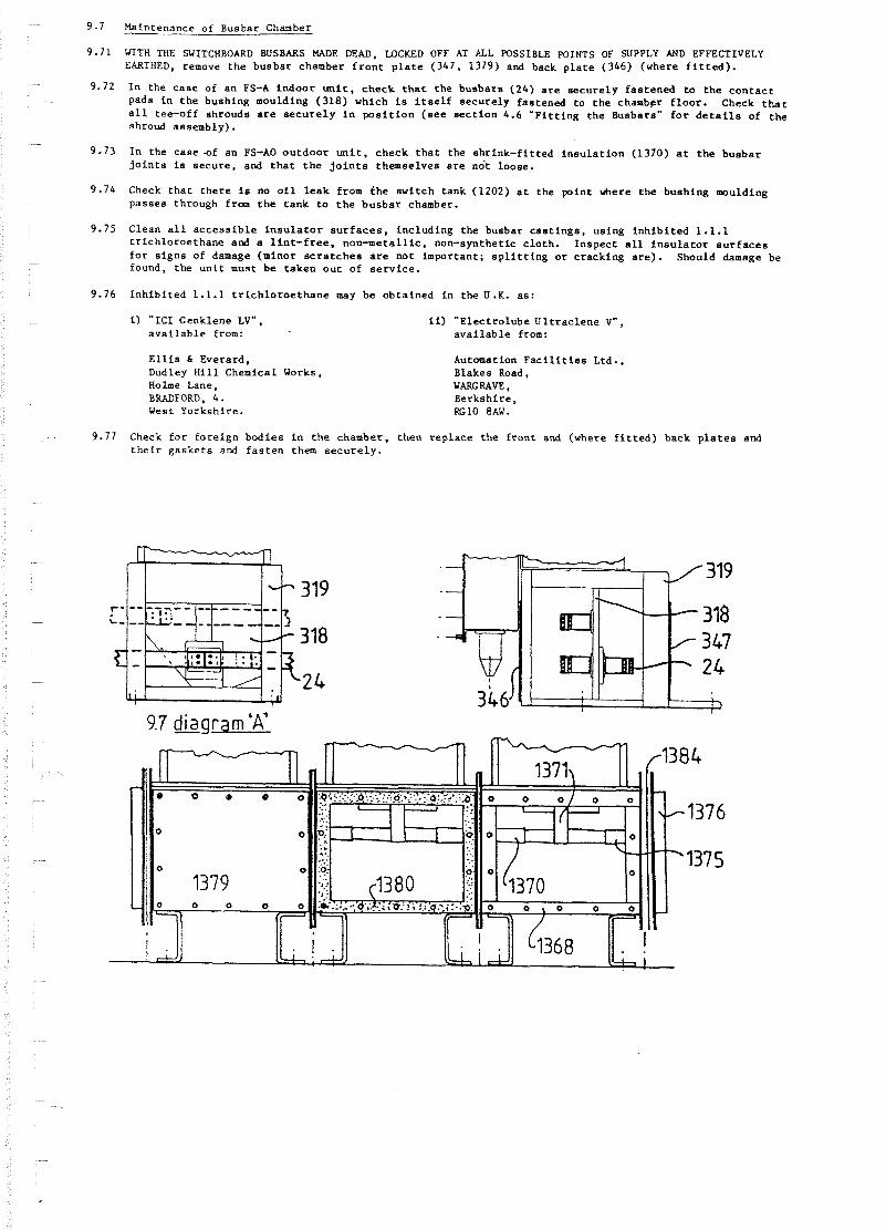
9.7 Maintenance of Busbar Chamber - 9.71 WITH THE SWITCHBOARD BUSBARS W E DEAD, WCKED OFF AT ALL POSSIBLE POINTS OF SUPPLY AND EFFECTIVELY
EARTHED, remove t h e busbar chamber f r o n t p l a t e (347 , 1379) and back p l a t e (346) ( v h e r e f i t t e d ) .
9.72 I n t h e c a s e of a n FS-A i n d o o r u n i t , c h e c k t h a t t h e b u s b a r s (24) a r e s e c u r e l y f a s t e n e d t o t h e c o n t a c t pads i n t h e bush ing moulding (318) v h i c h is i t s e l f s e c u r e l y fas tened t o t h e chamb9r f l o o r . Check t h a t a l l tee-off shrouds a r e s e c u r e l y i n p o s i t i o n ( s e e s e c t i o n 4.6 " F i t t i n g t h e Busbars" f o r d e t a i l s of t h e shroud assembly).
9.73 I n t h e c a s e -of a n FS-A0 o u t d o o r u n i t , check t h a t t h e s h r i n k - f i t t e d i n s u l a t i o n (1370) a t t h e b u s b a r j o i n t s is s e c u r e , and t h a t t h e j o i n t s themselves a r e n o t loose .
9.74 Check t h a t t h e r e is no o i l l e a k from t h e s v i t c h tank (1202) a t t h e p o i n t where t h e bush ing moulding passes through from t h e t a n k t o t h e b u s b a r chamber.
9.75 Clean a l l a c c e s s i b l e i n s u l a t o r s u r f a c e s , i n c l u d i n g t h e busbar c a s t i n g s , us ing i n h i b i t e d 1.1.1 t r i c h l o r o e t h a n e and a l i n t - f r e e , n o r r m e t a l l i c , non-synthetic c l o t h . I n s p e c t a l l i n s u l a t o r s u r f a c e s f o r s i g n s of damage (minor s c r a t c h e s a r e n o t impor tan t ; s p l i t t i n g o r c r a c k i n g a r e ) . Should damage be found, t h e u n i t must b e t a k e n o u t of s e r v i c e .
9.76 I n h i b i t e d 1.1.1 t r i c h l o r o e t h a n e may be o b t a i n e d i n t h e U . K . a s :
I) "KC1 Genklene LV". a v a i l a b l e from:
E l l i s b Everard , Dudley H i l l Chemical Works, Holme Lane, BRADFORD, 4. West Yorksh i re .
i i ) " E l e c t r o l u b e U l t r a c l e n e V" , a v a i l a b l e from:
Automation F a c i l i t i e s Ltd., Blakes Road, WARG RAVE, B e r k s h i r e , RGlO 8AW.
9.77 Check f o r f o r e i g n b o d i e s i n t h e chamber, t h e n r e p l a c e t h e f r o n t and (where f i t t e d ) back p l a t e s and t h e i r g a s k e t s and f a s t e n them s e c u r e l y .
9.7 diagram 'A'

1 0 SPARES AND TOOLS
1 0 . 1 Spare P a r t s
10.11 S e r v i c e e x p e r i e n c e v i t h e a r l i e r d e s i g n s of fuse swi tch has shovn t h a t t h e need f o r t h e rep lacement of any p a r t of an FS-A f u s e s w i t c h w i l l v e r y r a r e l y a r i s e .
10.12 I n view of t h i s f a c t o r , of the v i d e v a r i e t y of d u t i e s and environments t o vhich u n i t s may be s u b j e c t e d and of the d e t a i l e d v a r i a t i o n s i n equipment between i n d i v i d u a l i n s t a l l a t i o n s , i t is o u r p o l i c y t o recommend s p a r e p a r t s on an i n d i v i d u a l c o n t r a c t b a s i s r a t h e r than to i s s u e a g e n e r a l l ist of recornended s p a r e s .
10.13 Should any p a r t be r e q u i r e d which was.not i n i t i a l l y provided a s a s p a r e , t h e e n q u i r y should i n c l u d e t h e s e r i a L number of t h e u n i t , t h e i n f o r m a t i o n quoted on t h e d a t a p l a t e and, vhere p o s s i b l e , t h e o r i g i n a l c o n t r a c t number. Where r e l e v a n t , r e f e r e n c e s t o i l l u s t r a t i o n s and p a r t key numbers used i n t h i s manual may a s s i s t i n t h e identification of t h e component t o be reneved e .g . :
10.14 FS-A f u s e swi tch , s e r i a l No. 0100234, 15.5kV, 21.9kA, 150A, 50160Hz.
T r i p bar assembly, key No. 1112, a s i l l u s t r a c e d i n 2.1 and 2.2 diagram "D", i n t h e manual d a t e d August , 1981, r e f e r e n c e : D49-PI-39.
10.15 Whi ls t no t a l l of t h e i n f o r m a t i o n quoted w i l l always be d i r e c t l y r e l e v a n t o r e s s e n t i a l , i t may h e l p t o d i s t i n g u i s h between d e s i g n s having minor d e t a i l v a r i a t i o n s .
10.21 No spec iaL t o o l s a r e r e q u i r e d f o r t h i s equipment.
10.22 Open-ended and r i n g spanners :
Y e t r i c d i a : Xh X 5 Y6 58 X10 HI2 N 1 6
Y e t r i c A / F : 7 m 8 - 1 0 m 1 3 m m 17mm 17mm 24mm
10.23 P lus normal vorkshop t o o l s such a s s c r e w d r i v e r s , p l i e r s , d r i f t s , hammers, f i l e s e t c .

K E Y TO ILLUSTRATIONS (FS-A, FS-AO, FS-AT)
Busbars (FS-A) F l e x i b l e an t i -ve rmin s t r i p s (FS-A) Busbar end p l a t e (FS-A) Busbar s e c u r i n g s t u d s (FS-A) Busbar t ee -of f c o n n e c t i o n p l a t e s ( i n s e t ) (FS-A) Busbar f i s h p l a t e s p a c e r s (FS-A) Busbar j o i n t box (FS-A) Busbar j o i n t box end p i e c e (FS-A) l O l ( a ) s i n g l e t y p e f o r 800A b u s b a r s 101(b) d o u b l e t y p e f o r 1250A b u s b a r p 1 0 1 ( c ) d o u b l e t y p e f o r 2000A busbar; 101(d) s i n g l e b l a n k t y p e f o r end p a n e l Busbar p a c k e r f o r u s e on end p a n e l s (FS-A) Busbar j o i n t box c o v e r (Fs-A) Uni t - to -un i t r i g i d c o v e r p l a t e s t o p r o t e c t b u s b a r s (FS-A) U n i s t r u t c h a n n e l s , Ref. P3200 F l o o r c h a s e s t o t a k e (181) S p r i n g n u t s , M10, f o r ( 1 8 1 ) ' Ref. PI008 T i e b a r f i g s f o r (181) MI0 b o l t s f o r (183) Fuses E a r t h b a r C a s t r e s i n busbar s u p p o r t i n s u l a t o r (FS-A) A i r i n s u l a t e d b u s b a r chamber (FS-A) Busbar chamber b a s e p l a t e (FS-A) Busbar chamber back p l a t e (FS-A) Busbar chamber f r o n t p l a t e (FS-A) Main f u s e s w i t c h moving c o n t a c t s Main f u s e s v i t c h f i x e d c o n t a c r a s s e m b l i e s , engaged by (1101) and (1117) E a r t h s w i t c h f i x e d c o n t a c t s Main f u s e s w i t c h mechanism Fuse c a r r i a g e ( i n s u l a t e d c o n s t r u c t i o n ) on (1108) E a r t h s w i t c h mechanism Mechanism mainframe Annula r s l i d i n g c o n t a c t w i t h (1101) Lower f u s e c o n t a c t cups ( a ) f o r 254 mm ( 1 0 i n ) f u s e s
( b ) f o r 359 m (14 .1 /8 i n ) f u s e s I n s u l a t e d d r i v e l i n k s between (1105) and (1101) Main f u s e s w i t c h t r i p b a r Outgo ing c i r c u i t b u s h i n g s F ixed c o n t a c t s c o n n e c t e d t o ( 3 1 8 ) Main s w i t c h pad lock p o i n t Hinged MOVE BEFORE EARTHING P a d l o c k a b l e l i n k Main s w i t c h h a n d l e s t u b : ON p o s i t i o n Main s v i t c h h a n d l e s t u b : OFF p o s i t i o n Main s w i t c h h a n d l e s t u b : RESET p o s i t i o n E a r t h s w i t c h h a n d l e s t u b : EARTH ON p o s i t i o n E a r t h s w i t c h h a n d l e s t u b : EARTH OFF p o s i t i o n Removable o p e r a t i n g h a n d l e ( d e s i g n s v a r y ) C a r r i a g e r e t a i n i n g c l i p Cover r o l l e r a t t o p of ( 1 1 0 8 ) : engages (1159) Mainframe l i f t i n g s p r i n g s t o r a i s e (1108) ON~OFFIEARTH ON i n d i c a t i o n v i s i b l e th rough t a n k window Hinged upper f u s e c o n t a c t c l i p I n s u l a t e d f r o n t c o v e r p l a t e t o (1106) .%in s w i t c h main s h a f t Main s w i t c h s t o p p i n engaged by ( 1 1 4 7 ) Main s w i t c h c l o s i n g s p r i n g wind ing l e v e r b i n s w i t c h c l o s i n g s p r i n g b i n s w i t c h d i s c r a t c h e t d r i v e l e v e r Main s w i t c h r o t o r r e l e a s e l e v e r b i n s v i t c h t r i p c a t c h Main s w i t c h open ing s p r i n g s Neoprene-bonded g a s k e t s a s a l t e r n a t i v e t o (1180) on c a b l e box "a in s v i t c h s t o p and r e v e r s e motion t r i p l e v e r on (1133) % i n s w i t c h r e v e r s e mot ion t r i p b o l t Main s v i t c h t r i p b a r t r i p l e v e r E a r t h s v i t c h mechanism s h a f t E a r t h s w i t c h s p r i n g compress ion l e v e r E a r t h s v i t c h o p e r a t i n g s p r i n g s E a r t h s w i t c h t o g g l e l e v e r E a r t h s v i t c h t o g g l e d r i v e l i n k E a r t h s v i t c h t o g g l e qudger E a r t h s v i t c h i n d i c a t i o n d r i v e l i n k E a r t h s v i t c h s i d e arms a t e n d s o f (1197) % i n s v i t c h / e a r t h s v i t c h i n t e r l o c k l e v e r ( a ) head
( b ) t a i l ? iechanism/cover r o l l e r b r a c k e t engaged by (1128) Outgoing c i r c u i t moving i s o l a t i n g c o n t a c t on (1106) Outgoing c i r c u i t f i x e d i s o l a t i n g c o n t a c t on (1114) Trans former HV f l a n g e Cable box ( a ) r e a r mounted
( b ) f r o n t mounted (FS-AT)

Angle i r o n s t a n d (FS-AT) F lange around (1114) (FS-AT) O p e r a t i n g p l a t f o r m (FS-AT) Rag-bolt f l o o r f i x i n g s (FS-AO. AT) Cable g l a n d s Gaske t between (1165) and (1168) (FS-AT) Cable box (1166) f r o n t p l a t e Cable s o c k e t s i n (1166) Gasket between (1184) and (1171) P r e s s u r e p l a s t i c - a l t e r n a t i v e t o (1146) on c a b l e box '
Cable box (1166) bottom p l a t e Cable box (1166) f i l l i n g a p e r t u r e cover Cable box (1166) f i l l i n g a p e r t u r e a Cable box (1166) f i l l i n g a p e r t u r e g a s k e t E a r t h s w i t c h d r i v e c r a n k I n t e r l o c k cam on (1133) i n t e r a c t s w i t h (1158b) I n t e r l o c k a m on (1157) i n t e r a c t s w i t h (1207) and (1209) Main s w i t c h mechanism s p u r g e a r s Ear th s w i t c h mechanism wip ing c o n t a c t EARTH ON i n d i c a t o r p l a t e E a r t h s w i t c h moving c o n t a c t s Main s w i t c h main l e v e r s ( s e t of t h r e e ) Main s w i t c h r o t o r r e l e a s e c a t c h Main s w i t c h d i s c r a t c h e t Main s w i t c h r o t o r O i l t a n k Mechanism frame member
Tank cover I n t e r l o c k p i n on t a n k s i d e (engages 1207) Main s w i t c h d r i v e c r a n k E a r t h s w i t c h i n d i c a t i o n d r i v e s h a f t d r i v e n by (1156) I n t e r l o c k p i n on t a n k s i d e ( e n g a g e s 1193) ON/OFF i n d i c a t o r p l a t e on c e n t r a l main l e v e r (1198) P in on tank f r o n t w a l l engaged by (1210) F in on (1198) engaged b y (1158b) Rotor a r r e s t o r s p r i n g Busbar chamber ( FS-AO) Busbars (FS-AO) Heat s h r i n k a b l e busbar c o n n e c t i o n i n s u l a t i n g s l e e v e (FS-AO) Resin moulding i n c o r p o r a t i n g (1369) (FS-AO) S p l i t m e t a l s l e e v e f o r b u s b a r j o i n t (FS-AO) Heat s h r i n k a b l e m e t a l l o c k i n g r i n g s t o s e c u r e (1372) i n p o s i t i o n (FS-AO) Metal bush f o r end of (1369) on end panel (FS-AO) Heat s h r i n k a b l e i n s u l a t i n g "boot" f o r (1369/1374) on end p a n e l s (FS-AO) Busbar chamber end cover (FS-AO) U n i s t r u t t i e b a r j i g s (FS-AO) Busbar chamber f l a n g e (FS-AO) Busbar chamber f r o n t c o v e r (FS-AO) Gaske t f o r (1379) (FS-AO) Busbar chamber r a i n s h e d s (FS-AO) Removable f e e t (FS-AO) Gasket f o r (1376) (FS-AO) Aluminium f o i l h e a t s h i e l d f o r (1370) (FS-AO)