INSTRUCTION MANUAL SELF RETRACTING LIFELINES · Avoid working where your lifeline may cross or...
24
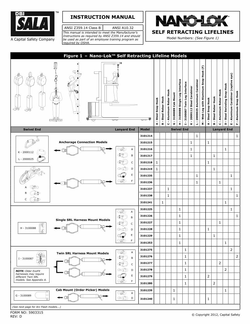
© Copyright 2012, Capital Safety A Capital Safety Company ANSI Z359.14 Class B ANSI A10.32 This manual is intended to meet the Manufacturer’s Instructions as required by ANSI Z359.14 and should be used as part of an employee training program as required by OSHA. INSTRUCTION MANUAL Figure 1 – Nano-Lok™ Self Retracting Lifeline Models A - Steel Snap Hook B - Steel Rebar Hook C - Aluminum Rebar Hook G - 3100089 Cab Mount H - 3100088 Single Leg Interface I - 3100087 Twin Leg Interface K - 2000112 Steel Carabiner L - 2000025 Aluminum Carabiner M - Web Leg with Aluminum Snap Hook (F) A - Steel Snap Hook B - Steel Rebar Hook C - Aluminum Rebar Hook D - Steel Swiveling Snap Hook E - Aluminum Carabiner (captive eye) F - Aluminum Snap Hook Swivel End Lanyard End Model Swivel End Lanyard End K - 2000112 L - 2000025 Anchorage Connection Models A B C D E F A B C 3101214 1 1 3101215 1 1 3101216 1 1 3101217 1 1 3101218 1 1 3101219 1 1 3101235 1 1 3101236 1 1 3101237 1 1 3101238 1 1 3101241 1 1 H - 3100088 Single SRL Harness Mount Models A B C D E F 3101225 1 1 3101226 1 1 3101227 1 1 3101228 1 1 3101229 1 1 3101253 1 1 I - 3100087 NOTE: Older ExoFit harnesses may require different Twin SRL models. See Appendix A. Twin SRL Harness Mount Models A B C D E F 3101275 1 2 3101276 1 2 3101277 1 2 3101278 1 2 3101279 1 2 3101280 1 2 G - 3100089 Cab Mount (Order Picker) Models A D 3101239 1 1 3101240 1 1 (See next page for Arc Flash models...) FORM NO: 5903315 REV: D SELF RETRACTING LIFELINES Model Numbers: (See Figure 1)
Transcript of INSTRUCTION MANUAL SELF RETRACTING LIFELINES · Avoid working where your lifeline may cross or...
© Copyright 2012, Capital Safety
A Capital Safety Company
ANSI Z359.14 Class B ANSI A10.32This manual is intended to meet the Manufacturer’s Instructions as required by ANSI Z359.14 and should be used as part of an employee training program as required by OSHA.
INSTRUCTION MANUAL
Figure 1 – Nano-Lok™ Self Retracting Lifeline Models
A -
Ste
el
Sn
ap
Ho
ok
B -
Ste
el
Reb
ar
Ho
ok
C -
Alu
min
um
Reb
ar
Ho
ok
G -
31
00
08
9 C
ab
Mo
un
t
H -
31
00
08
8 S
ing
le L
eg
In
terf
ace
I -
31
00
08
7 T
win
Leg
In
terf
ace
K -
20
00
11
2 S
teel
Cara
bin
er
L -
20
00
02
5 A
lum
inu
m C
ara
bin
er
M -
Web
Leg
wit
h A
lum
inu
m S
nap
Ho
ok (
F)
A -
Ste
el
Sn
ap
Ho
ok
B -
Ste
el
Reb
ar
Ho
ok
C -
Alu
min
um
Reb
ar
Ho
ok
D -
Ste
el
Sw
iveli
ng
Sn
ap
Ho
ok
E -
Alu
min
um
Cara
bin
er
(cap
tive e
ye)
F -
Alu
min
um
Sn
ap
Ho
ok
Swivel End Lanyard End Model Swivel End Lanyard End
K - 2000112
L - 2000025
Anchorage Connection Models
A
B
C
D
E
F
A
B
C
3101214 1 1
3101215 1 1
3101216 1 1
3101217 1 1
3101218 1 1
3101219 1 1
3101235 1 1
3101236 1 1
3101237 1 1
3101238 1 1
3101241 1 1
H - 3100088
Single SRL Harness Mount Models
A
B
C
D
E
F
3101225 1 1
3101226 1 1
3101227 1 1
3101228 1 1
3101229 1 1
3101253 1 1
I - 3100087
NOTE: Older ExoFit harnesses may require different Twin SRL models. See Appendix A.
Twin SRL Harness Mount Models A
B
C
D
E
F
3101275 1 2
3101276 1 2
3101277 1 2
3101278 1 2
3101279 1 2
3101280 1 2
G - 3100089
Cab Mount (Order Picker) ModelsA
D
3101239 1 1
3101240 1 1
(See next page for Arc Flash models...)
FORM NO: 5903315REV: D
SELF RETRACTING LIFELINESModel Numbers: (See Figure 1)

Figure 1 – Nano-Lok™ Self Retracting Lifeline Models
A -
Ste
el
Sn
ap
Ho
ok
B -
Ste
el
Reb
ar
Ho
ok
C -
Alu
min
um
Reb
ar
Ho
ok
G -
31
00
08
9 C
ab
Mo
un
t
H -
31
00
08
8 S
ing
le L
eg
In
terf
ace
I -
31
00
08
7 T
win
Leg
In
terf
ace
K -
20
00
11
2 S
teel
Cara
bin
er
L -
20
00
02
5 A
lum
inu
m C
ara
bin
er
M -
Web
Leg
wit
h A
lum
inu
m S
nap
Ho
ok (
F)
A -
Ste
el
Sn
ap
Ho
ok
B -
Ste
el
Reb
ar
Ho
ok
C -
Alu
min
um
Reb
ar
Ho
ok
D -
Ste
el
Sw
iveli
ng
Sn
ap
Ho
ok
E -
Alu
min
um
Cara
bin
er
(cap
tive e
ye)
F -
Alu
min
um
Sn
ap
Ho
ok
Swivel End Lanyard End Model Swivel End Lanyard End
H - 3100088
Arc Flash1
Single SRL Harness Mount Models
A
B
C
D
E
3101360 1 1
3101361 1 1
3101362 1 1
3101363 1 1
3101364 1 1
I - 3100087
Arc Flash1
Twin SRL Harness Mount Models A
B
C
D
E
3101380 1 2
3101381 1 2
3101382 1 2
3101383 1 2
3101384 1 2
K
M
Arc Flash1
Anchorage Connection Models A
E
3101385 1 1
3101375 1 1
3101358 1
Model 3101375 Bucket Truck Application
1 Arc Flash: SRL meets the test requirements of the ASTM F887-11 standard and is designed for use in environments where an arc fl ash (electrical explosion) could occur.

3
WARNING: This product is part of a personal fall arrest, work positioning, or rescue system. The user must follow the manufacturer’s instructions for each component of the system. These instructions must be provided to the user of this equipment. The user must read and understand these instructions before using this equipment. Manufacturer’s instructions must be followed for proper use and maintenance of this equipment. Alterations or misuse of this product or failure to follow instructions may result in serious injury or death.
IMPORTANT: If you have questions on the use, care, or suitability of this equipment for your application, contact Capital Safety.
IMPORTANT: Before using this equipment, record the product identifi cation information from the ID label in the inspection and maintenance log of this manual.
DESCRIPTIONS:
Figure 2 illustrates key components of the base Nano-Lok™ Self Retracting Lifeline (SRL). The Nano-Lok SRLs are 6 ft. (1.8 m) Lanyards, equipped with an in-line Load Indicator, which retract into a Thermoplastic Housing. They are available in multiple model confi gurations that allow attachment to an anchorage point, single or dual mounting on a Full Body Harness, or cab mounting on an Order Picker or similar equipment (see Figure 1). The Nano-Lok SRL automatically locks at the onset of a fall to arrest the fall, but pays out and retracts lifeline during normal movement by the attached user.
Figure 2 – Nano-Lok Self Retracting Lifeline (SRL) Components
B
D
E
F
G
H
A
C
A
D
E
F
G
H
A - Swivel B -Swivel Eye C - Integral Connector D - Housing E - Web Lifeline F - Load Indicator G - iSafe™ RFID Tag H - Snap Hook
4
1.0 APPLICATIONS
1.1 PURPOSE: Capital Safety Self Retracting Lifelines (SRLs) are designed to be a component in a personal fall arrest system (PFAS). Figure 1 illustrates SRLs covered by this instruction manual and their typical applications. They may be used in most situations where a combination of worker mobility and fall protection is required (i.e. inspection work, general construction, maintenance work, oil production, confi ned space work, etc.).
1.2 STANDARDS: Your SRL conforms to the national standard(s) identifi ed on the front cover of these instructions. Refer to local, state, and federal (OSHA) requirements governing occupational safety for additional information regarding Personal Fall Arrest Systems. Refer to the following national standards on fall protection:
ANSI Z359.0 Defi nitions and Nomenclature Used for Fall Protection and Fall Arrest
ANSI Z359.1 Safety Requirements for Personal Fall Arrest Systems, Subsystems, and Components
ANSI Z359.2 Minimum Requirements for a Comprehensive managed Fall Protection Program
ANSI A10.32 Personal Fall Protection use in Construction and Demolition
1.3 TRAINING: This equipment is intended to be used by persons trained in its correct application and use. It is the responsibility of the user to assure they are familiar with these instructions and are trained in the correct care and use of this equipment. Users must also be aware of the operating characteristics, application limits, and the consequences of improper use.
2.0 LIMITATIONS & REQUIREMENTS
Always consider the following limitations and requirements when installing or using this equipment:
2.1 CAPACITY: SRLs are designed for use by one person with a combined weight (person, clothing, tools, etc.) not exceeding 420 lbs (190 kg).
At no time shall more than one person connect to a single SRL for fall arrest applications.
2.2 MAXIMUM ARREST FORCE AND MAXIMUM ARREST DISTANCE: SRLs documented in this instruction meet the following Arrest Force and Arrest Distance maximums:
Weight of Worker Up to 310 lbs (141 kg) Greater than 310 lbs (141 kg) Up to 420 lbs (191 kg)
Average Arresting Force 900 lbs (4.0 kN) 900 lbs (4.0 kN)
Maximum Arresting Force 1,350 lbs (6.0 kN) 1,350 lbs (6.0 kN)
Maximum Arrest Distance 30 in (0.76 m) 36 in (0.9 m)
2.3 ANCHORAGE: Anchorages selected for fall arrest systems shall have a strength capable of sustaining static loads applied in the directions permitted by the system of at least:
1. 5,000 lbs. (22.2 kN) for non-certifi ed anchorages, or2. Two times the maximum arresting force for certifi ed anchorages.
When more than one fall arrest system is attached to an anchorage, the strengths set forth in (1) and (2) above shall be multiplied by the number of systems attached to the anchorage.
FROM OSHA 1926.500 AND 1910.66: Anchorages used for attachment of personal fall arrest systems shall be independent of any anchorage being used to support or suspend platforms, and capable of supporting at least 5,000 lbs. per user attached, or be designed, installed, and used as part of a complete personal fall arrest systems which maintains a safety factor of at least two, and is under the supervision of a qualifi ed person.
2.4 RESCUE PLAN: When using this equipment, the employer must have a rescue plan and the means at hand to implement it and communicate that plan to users, authorized persons, and rescuers.
2.5 INSPECTION FREQUENCY: SRLs shall be inspected by the authorized person1 or rescuer2 before each use. Additionally, inspections shall be conducted by a competent person3 other than the user, and by a factory authorized inspection entity. The competent person shall use the Inspection Schedule (Table 1) to determine appropriate inspection intervals. Inspection procedures are described in the “Inspection Checklist” (Table 2). Results of the Competent Person inspection should be recorded in the “Inspection and Maintenance Log” on the back pages of these instructions or recorded with the i-Safe™ system (see Section 5).
1 Authorized Person: A person assigned by the employer to perform duties at a location where the person will be exposed to a fall hazard.
2 Rescuer: Person or persons other than the rescue subject acting to perform an assisted rescue by operation of a rescue system.
3 Competent Person: An individual designated by the employer to be responsible for the immediate supervision, implementation, and monitoring of the employ-er’s managed fall protection program who, through training and knowledge, is capable of identifying, evaluating, and addressing existing and potential fall hazards, and who has the employer’s authority to take prompt corrective action with regard to such hazards.

5
Table 1 – Inspection Schedule
Type of UseApplication Examples Conditions of Use
Inspection FrequencyCompetent Person Factory Authorized
Infrequent to Light Rescue and Confi ned Space, Factory Maintenance
Good Storage Conditions, Indoor or Infrequent Outdoor Use, Room Temperature, Clean Environments
Annually At Least Every 2-5 Years, but not longer than intervals required by the manufacturer
Moderate to Heavy Transportation, Residential Construction, Utilities, Warehouse
Fair Storage Conditions, Indoor and Extended Outdoor Use, All Temperatures, Clean or Dusty Environments
Semi-Annually to Annually
At Least Every 1-2 Years, but not longer than intervals required by the manufacturer
Sever to Continuous Commercial Construction, Oil and Gas, Mining
Harsh Storage Conditions, Prolonged or Continuous Outdoor Use, All Temperatures, Dirty Environment
Quarterly to Semi-Annually
At Least Annually, but not longer than intervals required by the manufacturer
2.6 LOCKING SPEED: Situations which do not allow for an unobstructed fall path should be avoided. Working in confined or cramped spaces may not allow the body to reach sufficient speed to cause the SRL to lock if a fall occurs. Working on slowly shifting material, such as sand or grain,may not allow enough speed buildup to cause the SRL to lock. A clear path is required to assure positive locking of the SRL.
2.7 NORMAL OPERATIONS: Normal operation will allow the full length of the lifeline to extend and retract with no hesitation when extending and no slack when retracting as the worker moves at normal speeds. If a fall occurs, a speed sensing brake system will activate, stopping the fall and absorbing much of the energy created. For falls which occur near the end of the lifeline travel, a reserve lifeline system or Load Indicator has been incorporated to assure a reduced impact fall arrest. If the SRL has been subjected to fall forces, remove the SRL from service, mark “UNUSABLE”, and dispose of in the recommended manner (see “Section 5.5 - Disposal”). Sudden or quick movements should be avoided during normal work operation, as this may cause the SRL to lock up.
2.8 FREE FALL: When anchored overhead, SRLs will limit the free fall distance to 2 ft. (61 cm) or less. To avoid increased fall distances, anchor the SRL directly above the work level. Avoid working where your lifeline may cross or tangle with that of another worker. Avoid working where an object may fall and strike the lifeline; resulting in loss of balance or damage to the lifeline. Do not allow the lifeline to pass under arms or between legs. Never clamp, knot, or prevent the lifeline from retracting or being taut. Avoid slack line. Do not lengthen SRL by connecting a lanyard or similar component without consulting Capital Safety.
2.9 FALL CLEARANCE: Figure 3A illustrates Fall Clearance requirements. Ensure adequate clearance exists in the fall path to prevent striking an object during a fall. If the worker will be working at a position that is not directly below the SRL anchorage point, the clearance required and vertical fall distance will be greater.
2.10 SWING FALLS: Swing falls occur when the anchorage point is not directly above the point where a fall occurs (see Figure 3B). The force of striking an object in a swing fall may cause serious injury. In a swing fall, the total vertical fall distance will be greater than if the user had fallen directly below the anchorage point, thus increasing fall clearance required to safely arrest the user. Use Figure 3A to determine the fall clearance for your application. Minimize swing falls by working as directly below the anchorage point as possible. Never permit a swing fall if injury could occur.
2.11 HAZARDS: Use of this equipment in areas where surrounding hazards exist may require additional precautions to reduce the possibility of injury to the user or damage to the equipment. Hazards may include, but are not limited to: high heat, caustic chemicals, corrosive environments, high voltage power lines, explosive or toxic gases, moving machinery, sharp edges, or overhead materials that may fall and contact the user or fall arrest system.
2.12 SHARP EDGES: Avoid working where the lifeline will be in contact with or abrade against unprotected sharp edges. Where contact with a sharp edge is unavoidable, cover the edge with a protective material.
2.13 BODY SUPPORT: A Full Body Harness must be used with the Self Retracting Lifeline. The harness connection point must be above the user’s center of gravity. A body belt is not authorized for use with the Self Retracting Lifeline. If a fall occurs when using a body belt it may cause unintentional release and possible suffocation because of improper body support.
2.14 COMPATIBILITY OF COMPONENTS: Unless otherwise noted, Capital Safety equipment is designed for use with Capital Safety approved components and subsystems only. Substitutions or replacements made with non approved components or subsystems may jeopardize compatibility of equipment and may affect safety and reliability of the complete system.
IMPORTANT: Read and follow manufacturer’s instructions for associated components and subsystems in your personal fall arrest system.

6
Figure 3 – Fall Clearance and Swing Falls
Figure 3A:
Clearance required in feet (meters) between Working Level and Nearest Obstruction for User with Total Weight up to 310 lbs (141 kg)
Clearance between Working Level and
Nearest Obstruction
Figure 3B:
Swing Falls
Clearance between Working Level and
Nearest Obstruction
To determine the clearance required: Measure the distance from the user’s harness dorsal connection to the anchorage for the Nano-Lok SRL. Both horizontal and vertical distances are required. Use Figure 3A above to determine the required clearance. The dotted lines in the fi gure represent 1 foot (0.3 m) increments from the user’s harness dorsal connection to the anchorage. For example, 6 ft (1.8 m) of clearance is required when the Nano-Lok unit is anchored 3 1/2 ft (1 m) above and 3 1/2 ft (1 m) to the side of the user’s harness dorsal connection, 12 ft (3.7 m) of clearance is required when the Nano-Lok is anchored 1 1/2 ft (0.5 m) below and 4 1/2 ft (1.4 m) to side of the user’s dorsal connection.
NOTE: The clearances provided above assume the fall occurs from the standing position. If the worker is kneeling or crouching an additional 3 ft (0.9 m) of clearance is needed.
USERS BETWEEN 310 AND 420 LBS (141-191 kg): Users with a combined weight (person, clothing, tools, etc.) between 310 and 420 lbs (141-191 kg) need 1 ft (0.3 m) more clearance than what is shown in the Figure 3A. 310 lb to 420 lb (141-191 kg)users must never anchor the Nano-Lok more than 2 ft (0.6 m) below their harness dorsal connection.
2.15 COMPATIBILITY OF CONNECTORS: Connectors are considered to be compatible with connecting elements when they have been designed to work together in such a way that their sizes and shapes do not cause their gate mechanisms to inadvertently open regardless of how they become oriented. Contact Capital Safety if you have any questions about compatibility.
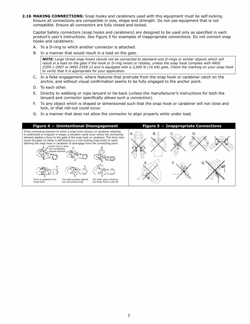
Connectors (hooks, carabiners, and D-rings) must be capable of supporting at least 5,000 lbs. (22.2 kN). Connectors must be compatible with the anchorage or other system components. Do not use equipment that is not compatible. Non-compatible connectors may unintentionally disengage (see Figure 4). Connectors must be compatible in size, shape, and strength. Self-locking snap hooks and carabiners are required by ANSI Z359 and OSHA.
7
2.16 MAKING CONNECTIONS: Snap hooks and carabiners used with this equipment must be self-locking. Ensure all connections are compatible in size, shape and strength. Do not use equipment that is not compatible. Ensure all connectors are fully closed and locked.
Capital Safety connectors (snap hooks and carabiners) are designed to be used only as specifi ed in each product’s user’s instructions. See Figure 5 for examples of inappropriate connections. Do not connect snap hooks and carabiners:
A. To a D-ring to which another connector is attached.
B. In a manner that would result in a load on the gate.
NOTE: Large throat snap hooks should not be connected to standard size D-rings or similar objects which will result in a load on the gate if the hook or D-ring twists or rotates, unless the snap hook complies with ANSI Z359.1-2007 or ANSI Z359.12 and is equipped with a 3,600 lb (16 kN) gate. Check the marking on your snap hook to verify that it is appropriate for your application.
C. In a false engagement, where features that protrude from the snap hook or carabiner catch on the anchor, and without visual confi rmation seems to be fully engaged to the anchor point.
D. To each other.
E. Directly to webbing or rope lanyard or tie-back (unless the manufacturer’s instructions for both the lanyard and connector specifi cally allows such a connection).
F. To any object which is shaped or dimensioned such that the snap hook or carabiner will not close and lock, or that roll-out could occur.
G. In a manner that does not allow the connector to align properly while under load.
Figure 4 – Unintentional Disengagement Figure 5 – Inappropriate ConnectionsIf the connecting element to which a snap hook (shown) or carabiner attaches is undersized or irregular in shape, a situation could occur where the connecting element applies a force to the gate of the snap hook or carabiner. This force may cause the gate (of either a self-locking or a non-locking snap hook) to open, allowing the snap hook or carabiner to disengage from the connecting point.
Small ring or other non-compatibly shaped element
Force is applied to the Snap Hook.
The Gate presses against the Connecting Ring.
The Gate opens allowing the Snap Hook to slip off.
A. B. C. D.
E. F. G.
8
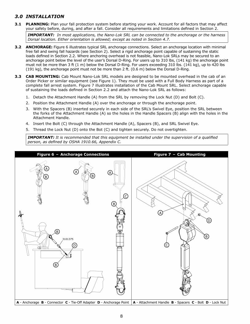
3.0 INSTALLATION
3.1 PLANNING: Plan your fall protection system before starting your work. Account for all factors that may affect your safety before, during, and after a fall. Consider all requirements and limitations defi ned in Section 2.
IMPORTANT: In most applications, the Nano-Lok SRL can be connected to the anchorage or the harness Dorsal location. Either orientation is allowed; except as noted in Section 4.7.
3.2 ANCHORAGE: Figure 6 illustrates typical SRL anchorage connections. Select an anchorage location with minimal free fall and swing fall hazards (see Section 2). Select a rigid anchorage point capable of sustaining the static loads defi ned in Section 2.2. Where anchoring overhead is not feasible, Nano-Lok SRLs may be secured to an anchorage point below the level of the user’s Dorsal D-Ring. For users up to 310 lbs, (141 kg) the anchorage point must not be more than 3 ft (1 m) below the Dorsal D-Ring. For users exceeding 310 lbs. (141 kg), up to 420 lbs (191 kg), the anchorage point must not be more than 2 ft. (0.6 m) below the Dorsal D-Ring.
3.3 CAB MOUNTING: Cab Mount Nano-Lok SRL models are designed to be mounted overhead in the cab of an Order Picker or similar equipment (see Figure 1). They must be used with a Full Body Harness as part of a complete fall arrest system. Figure 7 illustrates installation of the Cab Mount SRL. Select anchorage capable of sustaining the loads defi ned in Section 2.2 and attach the Nano-Lok SRL as follows:
1. Detach the Attachment Handle (A) from the SRL by removing the Lock Nut (D) and Bolt (C).
2. Position the Attachment Handle (A) over the anchorage or through the anchorage point.
3. With the Spacers (B) inserted securely in each side of the SRL’s Swivel Eye, position the SRL between the forks of the Attachment Handle (A) so the holes in the Handle Spacers (B) align with the holes in the Attachment Handle.
4. Insert the Bolt (C) through the Attachment Handle (A), Spacers (B), and SRL Swivel Eye.
5. Thread the Lock Nut (D) onto the Bot (C) and tighten securely. Do not overtighten.
IMPORTANT: It is recommended that this equipment be installed under the supervision of a qualifi ed person, as defi ned by OSHA 1910.66, Appendix C.
Figure 6 – Anchorage Connections Figure 7 – Cab Mounting
A
B BA
C
A
B
D
B
B
3101375
A
D
B
C
A - Anchorage B - Connector C - Tie-Off Adapter D - Anchorage Point A - Attachment Handle B - Spacers C - Bolt D - Lock Nut
9
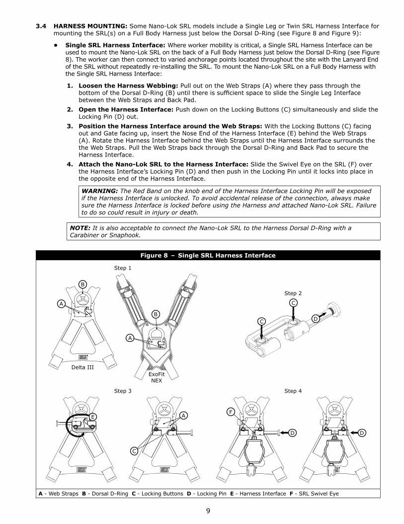
3.4 HARNESS MOUNTING: Some Nano-Lok SRL models include a Single Leg or Twin SRL Harness Interface for mounting the SRL(s) on a Full Body Harness just below the Dorsal D-Ring (see Figure 8 and Figure 9):
• Single SRL Harness Interface: Where worker mobility is critical, a Single SRL Harness Interface can be used to mount the Nano-Lok SRL on the back of a Full Body Harness just below the Dorsal D-Ring (see Figure 8). The worker can then connect to varied anchorage points located throughout the site with the Lanyard End of the SRL without repeatedly re-installing the SRL. To mount the Nano-Lok SRL on a Full Body Harness with the Single SRL Harness Interface:
1. Loosen the Harness Webbing: Pull out on the Web Straps (A) where they pass through the bottom of the Dorsal D-Ring (B) until there is suffi cient space to slide the Single Leg Interface between the Web Straps and Back Pad.
2. Open the Harness Interface: Push down on the Locking Buttons (C) simultaneously and slide the Locking Pin (D) out.
3. Position the Harness Interface around the Web Straps: With the Locking Buttons (C) facing out and Gate facing up, insert the Nose End of the Harness Interface (E) behind the Web Straps (A). Rotate the Harness Interface behind the Web Straps until the Harness Interface surrounds the the Web Straps. Pull the Web Straps back through the Dorsal D-Ring and Back Pad to secure the Harness Interface.
4. Attach the Nano-Lok SRL to the Harness Interface: Slide the Swivel Eye on the SRL (F) over the Harness Interface’s Locking Pin (D) and then push in the Locking Pin until it locks into place in the opposite end of the Harness Interface.
WARNING: The Red Band on the knob end of the Harness Interface Locking Pin will be exposed if the Harness Interface is unlocked. To avoid accidental release of the connection, always make sure the Harness Interface is locked before using the Harness and attached Nano-Lok SRL. Failure to do so could result in injury or death.
NOTE: It is also acceptable to connect the Nano-Lok SRL to the Harness Dorsal D-Ring with a Carabiner or Snaphook.
Figure 8 – Single SRL Harness Interface
Step 1
B
A
B
A
Delta IIIExoFitNEX
Step 2
C
C
D
Step 3
E A
C
Step 4
F
D D
A - Web Straps B - Dorsal D-Ring C - Locking Buttons D - Locking Pin E - Harness Interface F - SRL Swivel Eye
10
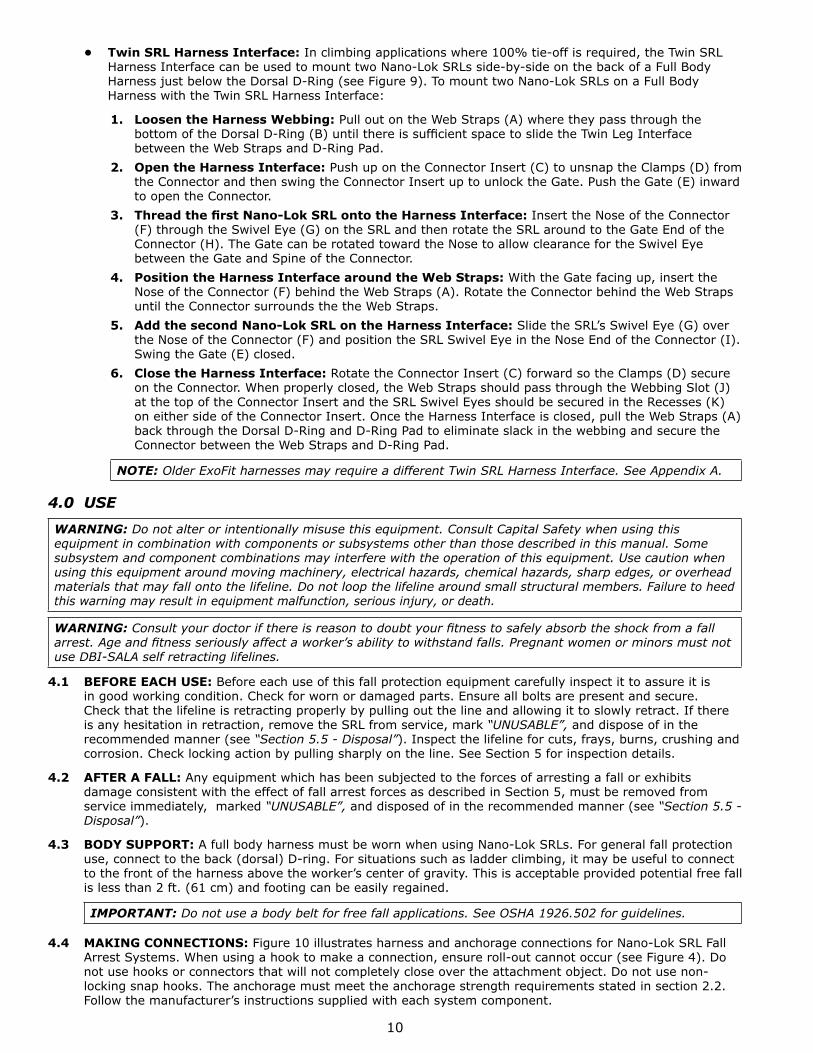
• Twin SRL Harness Interface: In climbing applications where 100% tie-off is required, the Twin SRL Harness Interface can be used to mount two Nano-Lok SRLs side-by-side on the back of a Full Body Harness just below the Dorsal D-Ring (see Figure 9). To mount two Nano-Lok SRLs on a Full Body Harness with the Twin SRL Harness Interface:
1. Loosen the Harness Webbing: Pull out on the Web Straps (A) where they pass through the bottom of the Dorsal D-Ring (B) until there is suffi cient space to slide the Twin Leg Interface between the Web Straps and D-Ring Pad.
2. Open the Harness Interface: Push up on the Connector Insert (C) to unsnap the Clamps (D) from the Connector and then swing the Connector Insert up to unlock the Gate. Push the Gate (E) inward to open the Connector.
3. Thread the fi rst Nano-Lok SRL onto the Harness Interface: Insert the Nose of the Connector (F) through the Swivel Eye (G) on the SRL and then rotate the SRL around to the Gate End of the Connector (H). The Gate can be rotated toward the Nose to allow clearance for the Swivel Eye between the Gate and Spine of the Connector.
4. Position the Harness Interface around the Web Straps: With the Gate facing up, insert the Nose of the Connector (F) behind the Web Straps (A). Rotate the Connector behind the Web Straps until the Connector surrounds the the Web Straps.
5. Add the second Nano-Lok SRL on the Harness Interface: Slide the SRL’s Swivel Eye (G) over the Nose of the Connector (F) and position the SRL Swivel Eye in the Nose End of the Connector (I). Swing the Gate (E) closed.
6. Close the Harness Interface: Rotate the Connector Insert (C) forward so the Clamps (D) secure on the Connector. When properly closed, the Web Straps should pass through the Webbing Slot (J) at the top of the Connector Insert and the SRL Swivel Eyes should be secured in the Recesses (K) on either side of the Connector Insert. Once the Harness Interface is closed, pull the Web Straps (A) back through the Dorsal D-Ring and D-Ring Pad to eliminate slack in the webbing and secure the Connector between the Web Straps and D-Ring Pad.
NOTE: Older ExoFit harnesses may require a different Twin SRL Harness Interface. See Appendix A.
4.0 USE
WARNING: Do not alter or intentionally misuse this equipment. Consult Capital Safety when using this equipment in combination with components or subsystems other than those described in this manual. Some subsystem and component combinations may interfere with the operation of this equipment. Use caution when using this equipment around moving machinery, electrical hazards, chemical hazards, sharp edges, or overhead materials that may fall onto the lifeline. Do not loop the lifeline around small structural members. Failure to heed this warning may result in equipment malfunction, serious injury, or death.
WARNING: Consult your doctor if there is reason to doubt your fi tness to safely absorb the shock from a fall arrest. Age and fi tness seriously affect a worker’s ability to withstand falls. Pregnant women or minors must not use DBI-SALA self retracting lifelines.
4.1 BEFORE EACH USE: Before each use of this fall protection equipment carefully inspect it to assure it is in good working condition. Check for worn or damaged parts. Ensure all bolts are present and secure. Check that the lifeline is retracting properly by pulling out the line and allowing it to slowly retract. If there is any hesitation in retraction, remove the SRL from service, mark “UNUSABLE”, and dispose of in the recommended manner (see “Section 5.5 - Disposal”). Inspect the lifeline for cuts, frays, burns, crushing and corrosion. Check locking action by pulling sharply on the line. See Section 5 for inspection details.
4.2 AFTER A FALL: Any equipment which has been subjected to the forces of arresting a fall or exhibits damage consistent with the effect of fall arrest forces as described in Section 5, must be removed from service immediately, marked “UNUSABLE”, and disposed of in the recommended manner (see “Section 5.5 - Disposal”).
4.3 BODY SUPPORT: A full body harness must be worn when using Nano-Lok SRLs. For general fall protection use, connect to the back (dorsal) D-ring. For situations such as ladder climbing, it may be useful to connect to the front of the harness above the worker’s center of gravity. This is acceptable provided potential free fall is less than 2 ft. (61 cm) and footing can be easily regained.
IMPORTANT: Do not use a body belt for free fall applications. See OSHA 1926.502 for guidelines.
4.4 MAKING CONNECTIONS: Figure 10 illustrates harness and anchorage connections for Nano-Lok SRL Fall Arrest Systems. When using a hook to make a connection, ensure roll-out cannot occur (see Figure 4). Do not use hooks or connectors that will not completely close over the attachment object. Do not use non-locking snap hooks. The anchorage must meet the anchorage strength requirements stated in section 2.2. Follow the manufacturer’s instructions supplied with each system component.
11
Figure 9 – Twin SRL Harness Interface
Step 1
A
B
B
ADelta III
ExoFitNEX
Step 2
D
D
C
E
Step 3
G
HF
Step 4
F
A
Step 5
F
EI
G
E
Step 6
DD
C
AD
D
KK
C
J
A - Web Straps B - Dorsal D-Ring C - Connector Insert D - Clamps, Connector Insert E - Gate, Connector F - Nose, Connector G - Swivel Eye, SRL H - Gate End, Connector I - Nose End, Connector J - Webbing Slot, Connector Insert K - Swivel Eye Recesses, Connector Insert

12
Figure 10 – Nano-Lok SRL System Connections
E
DA
D
G
B
F
C
F
A - Dorsal D-Ring B - Single SRL Harness Interface C - Twin SRL Harness Interface D - Snap Hook E - Carabiner F - Rebar Hook G - Anchorage Point
4.5 OPERATION: Prior to use, inspect the SRL as described in section 5.0. Figure 10 shows system connections for typical Nano-Lok SRL applications. Connect the Nano-Lok SRL to a suitable anchorage or mount the SRL on the back of a Full Body Harness per the instruction in Section 3. On anchorage connected SRLs, connect the Hook (D) or Carabiner on the Load Indicator to the Dorsal D-Ring (A) on the Full Body Harness. On harness mounted SRLs, connect the Hook (D) or Carabiner to a suitable anchorage. Ensure connections are compatible in size, shape, and strength. Ensure hooks are fully closed and locked. Once attached, the worker is free to move about within the recommended working area at normal speeds. If a fall occurs the SRL will lock and arrest the fall. Upon rescue, remove the SRL from use. When working with an SRL, always allow the lifeline to recoil back into the device under control.
WARNING: Do not tie or knot the lifeline. Avoid lifeline contact with sharp or abrasive surfaces. Inspect the lifeline frequently for cuts, fraying, burns, or signs of chemical damage. Dirt, contaminants, and water can lower dielectric properties of the lifeline. Use caution near power lines.
4.6 TWIN LEG INTERFACE 100% TIE-OFF: When two Nano-Lok SRLs are mounted side-by-side on the back of a Full Body Harness, the SRL Fall Arrest System can be used for continuous fall protection (100 % tie-off) while ascending, descending, or moving laterally (see Figure 11). With the Lanyard Leg of one SRL attached to an anchorage point, the worker can move to a new location, attach the unused Lanyard Leg of the other SRL to another anchorage point, and then disconnect from the original anchorage point. The sequence is repeated until the worker reaches the desired location. Considerations for twin leg 100% tie-off applications include the following:
• Connection of each Lanyard Leg to a separate anchorage point is acceptable (Figure 11).
• Never connect more than one person at a time to the Twin-Leg system (Figure 12).
• Do not allow the Lanyards to become tangled or twisted together as this may prevent them from retracting.
• Do not allow any lanyard to pass under arms or between legs during use.

13
Figure 11 – 100% Tie-Off Figure 12 – Incorrect Attachment
4.7 AERIAL WORK PLATFORMS: Use of the Nano-Lok SRL on aerial work platforms is permissible, provided the following criteria are met:
1. Nano-Lok SRLs generally will not restrain workers from falling out of aerial work platforms or elevated working surfaces. To restrain users from falling out of aerial work platforms, Positioning Lanyards of suffi ciently short lengths should be used.
2. Aerial work platforms must have guardrails or gates at all accessible edges along their perimeter unless anchorages for the Nano-Lok SRLs are located overhead. The edges on the top rails of all guardrails and gates over which the user might fall must have a minimum radius of 1/8 in. (0.3 cm).
3. Anchorages of appropriate strength and compatibility must always be used for securing Nano-Lok SRLs (see Section 2).
4. Swing fall hazards may exist, especially when working near corners or out away from anchorage points. Added fall clearance is needed where the potential for swing fall exists (see Figure 3).
5. All sharp edges which the Nano-Lok SRL’s lifeline may contact during a fall must be eliminated or covered over. All edges the SRL lifeline may contact in a fall must be smooth with an edge radius of 1/8 in. (0.3 cm) or greater. Potential pinch points between adjacent surfaces where the lifeline may catch during a fall must be eliminated.
4.8 HORIZONTAL SYSTEMS: In applications where the Nano-Lok SRL is used in conjunction with a horizontal system (i.e. Horizontal Lifeline, Horizontal I-Beams Trolley), the SRL and horizontal system components must be compatible. Horizontal systems must be designed and installed under the supervision of a qualifi ed engineer. Consult the horizontal system equipment manufacturer’s instructions for details.
5.0 INSPECTION
5.1 i-Safe™ RFID TAG: The Nano-Lok SRL includes an i-Safe™ Radio Frequency Identifi cation (RFID) tag. The RFID tag can be used in conjunction with the i-Safe handheld reading device to simplify inspection and inventory control and provide records for your fall protection equipment. If you are a fi rst-time user, contact a Capital Safety Customer Service representative (see back cover); or if you have already registered, go to isafe.capitalsafety.com. Follow the instructions provided with your i-Safe handheld reader or software to transfer your data to your database.
Figure 13 – i-Safe RFID Tag
5.2 INSPECTION FREQUENCY: The Nano-Lok SRL must be inspected at the intervals defi ned in “Section 2.5 - Inspection Frequency”. Inspection procedures are described in the “Inspection Checklist” (Table 2).
5.3 UNSAFE OR DEFECTIVE CONDITIONS: If inspection reveals an unsafe or defective condition, If inspection reveals an unsafe condition, remove the SRL from service, mark “UNUSABLE”, and dispose of in the recommended manner (see “Section 5.5 - Disposal”).
14
5.4 PRODUCT LIFE: The functional life of Nano-Lok SRLs is determined by work conditions and maintenance. As long as the SRL passes inspection criteria, it may remain in service.
5.5 DISPOSAL: Dispose of the Nano-Lok SRL if it has been subjected to fall force or inspection reveals an unsafe or defective condition. Before disposing of the SRL, cut the Load Indicator off of the Web Lanyard or otherwise disable the SRL to eliminate the possibility of inadvertent reuse.
6.0 MAINTENANCE, SERVICING, AND STORAGE
6.1 CLEANING: Cleaning procedures for the Nano-Lok SRL are as follows:
• Periodically clean the exterior of the SRL using water and a mild soap solution. Position the SRL so excess water can drain out. Clean labels as required.
• Clean the Web Lifeline with water and mild soap solution. Rinse and thoroughly air dry. Do not force dry with heat. The lifeline should be dry before allowing it to retract into the housing. An excessive buildup of dirt, paint, etc. may prevent the lifeline from fully retracting back into the housing causing a potential free fall hazard.
IMPORTANT: If the lifeline contacts acids or other caustic chemicals, remove the SRL from service and wash with water and a mild soap solution. Inspect the SRL per Table 2 before returning to service.
6.2 SERVICE: Nano-Lok SRLs are not repairable. If the SRL has been subjected to fall force or inspection reveals an unsafe or defective condition, remove the SRL from service, mark “UNUSABLE”, and dispose of in the recommended manner (see “Section 5.5 - Disposal”).
6.3 STORAGE: Store Nano-Lok SRLs in a cool, dry, clean environment out of direct sunlight. Avoid areas where chemical vapors may exist. Thoroughly inspect the SRL after any period of extended storage.
7.0 SPECIFICATIONS
7.1 PERFORMANCE: Your Nano-Lok SRL has been tested and certifi ed to the performance requirements of the standard(s) identifi ed on the cover of this instruction manual. See “Section 2.0 - Limitations & Requirements” for performance specifi cations.
7.2 MATERIALS: Material specifi cations for the Nano-Lok SRL are as follows:
Housing: Nylon, UV Resistant Motor Spring: Stainless Steel
Drum: Nylon, Type 6/6 Swivel: Zinc Plated Steel
Fasteners: Zinc Plated Steel Screws; Stainless Steel Rivets
Lifeline: Dynema Polyester Web
Arc Flash Models: Kevlar Web
Locking Pawls: Stainless Steel Load Indicator Cover: Denier Textured NylonStitching: Polyester or Nylon ThreadWeb: PolyesterMain Shaft: Stainless Steel
End Connectors:
See Figure 18 for End Connector options and their respective material specifi cations.
7.3 DIMENSIONS: Figure 18 lists Nano-Lok SRL dimensions. Average working range for the Nano-Lok SRL is 6 ft. (1.8 m), but will vary slightly with length differences in the various End Connector options. Retracted and Extended length values in Figure 18 are approximations based on the total length of the fully retracted/extended SRL and the applicable End Connectors.
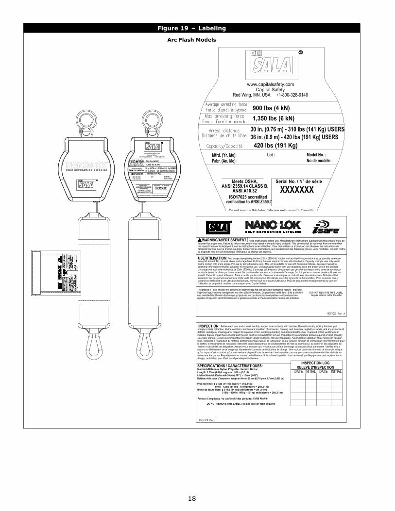
7.4 LABELING: Figure 19 illustrates Nano-Lok SRL labeling. All labels on the SRL must be present and fully legible.
15
Table 2 – Inspection Checklist
Component: Inspection: Pass Fail
SRL (Figure 14)
Inspect for loose fasteners and bent or damaged parts.
Inspect the Housing (A) for distortion, cracks, or other damage.
Inspect the Swivel (B) and Swivel Eye (C) or Integral Connector (D) for distortion, cracks, or other damage. The Swivel should be attached securely to the SRL, but should pivot freely. The Swivel Eye or Integral Connector should rotate freely in the Swivel.
The Web Lifeline (E) should pull out and retract fully without hesitation or creating a slack line condition.
Ensure the SRL locks up when the Lifeline is jerked sharply. Lockup should be positive with no slipping.
All labels must be present and fully legible (see Figure 19).
Inspect the entire SRL for signs of corrosion.
Web Lifeline(Figure 15)
Inspect the web lifeline for concentrated wear, frayed strands, broken yarn, burns, cuts, and abrasions. The lifeline must be free of knots throughout its length. Inspect for excessive soiling, paint build-up, and rust staining. Inspect for chemical or heat damage indicated by brown, discolored, or brittle areas. Inspect for ultraviolet damage indicated by discoloration and the presence of splinters and slivers on the lifeline surface.
Load Indicator(Figure 16)
Inspect the Load Indicator to determine if it has been activated. There should be no evidence of elongation and the cover should be secure and free of tears or other damage.
End Connectors(Figure 17)
Figure 1 identifi es the End Connectors that should be included on your Nano-Lok SRL model. Inspect all Snap Hooks, Carabiners, Rebar Hooks, Interfaces, etc. for signs of damage, corrosion, and proper working condition. Where present: Swivels (A) should rotate freely, Gates (B) should open, close, lock, and unlock properly, and Locking Buttons (C) and Locking Pins (D) should function correctly.
Figure 14 – SRL Inspection
CD
B B
A A
E E
Figure 15 – Web Lifeline
Cut
Frayed
HeavilySoiled
WeldingBurns
Figure 16 – Load Indicator
Torn orBrokenCover
Deployed andTorn/Frayed
Webbing
Figure 17 – End Connectors
B
BB B
B
A
B
C D C
B
16
Figure 18 – Dimensions & End Connector Specifi cations
1
A B C K
2000112
L
2000025
G
3100089
H
3100088
I
3100087
J
3100107
M
1 1 1
2 2
2
3 4
3.05”(77.5 mm)
3.46”(87.8 mm)
2.03”(51.7 mm)
12.5”(318 mm) 5’-6”
(1.68 m)
2
A B C D E F
End Connectors Length (Retracted) Length (Extended)
Model
1Swivel
2Lanyard
3in.
3mm
4ft.
4m
3101214 L F 22.75 577.85 6.35 1.94
3101215 K A 21.73 551.94 6.27 1.91
3101216 K D 22.02 559.31 6.29 1.92
3101217 K B 24.21 614.93 6.48 1.97
3101218 A A 22.30 566.42 6.32 1.93
3101219 A B 24.78 629.41 6.52 1.99
3101235 L E 22.00 558.80 6.29 1.92
3101236 L C 24.00 609.60 6.46 1.97
3101237 C E 26.50 673.10 6.67 2.03
3101238 C F 25.69 652.53 6.60 2.01
3101241 B D 21.19 538.23 6.22 1.90
3101225 H E 19.84 503.89 6.11 1.86
3101226 H F 20.59 522.94 6.17 1.88
3101227 H C 21.84 554.69 6.28 1.91
3101228 H A 18.74 475.95 6.02 1.83
3101229 H B 21.22 538.94 6.23 1.90
3101253 H D 19.03 483.31 6.04 1.84
3101275 I E 20.45 519.43 6.16 1.88
3101276 I F 21.20 538.48 6.23 1.90
3101277 I C 22.45 570.23 6.33 1.93
3101278 I D 19.64 498.86 6.10 1.86
3101279 I A 19.35 491.49 6.07 1.85
3101280 I B 21.83 554.48 6.28 1.91
3101271 J E 20.45 519.43 6.16 1.88
3101272 J F 21.20 538.48 6.23 1.90
3101273 J C 22.45 570.23 6.33 1.93
3101274 J D 19.64 498.86 6.10 1.86
3101287 J A 19.35 491.49 6.07 1.85
3101288 J B 21.83 554.48 6.28 1.91
3101239 G D 20.94 531.88 6.20 1.89
3101240 G A 20.65 524.51 6.18 1.88
3101358 M — 24.50 622.30 6.50 1.98
3101360 H D 19.03 483.31 6.04 1.84
3101361 H A 18.74 475.95 6.02 1.83
3101362 H B 21.22 538.94 6.23 1.90
3101363 H E 19.84 503.89 6.11 1.86
3101364 H C 21.84 554.69 6.28 1.91
3101375 M E 30.50 774.70 7.00 2.13
3101380 I A 19.35 491.49 6.07 1.85
3101381 I D 19.64 498.86 6.10 1.86
3101382 I B 21.83 554.48 6.28 1.91
3101383 I E 20.45 519.43 6.16 1.88
3101384 I C 22.45 570.23 6.33 1.93
3101385 K A 21.73 551.94 6.27 1.91
1 2Connector: Type: Material: Gate Opening Gate Strength
E Carabiner Aluminum 3/4 in.(19 mm)
3,600 lb(16 kN)
L Carabiner Aluminum 3/4 in.(19 mm)
3,600 lb(16 kN)
K Carabiner Steel 1-3/16 in.(30 mm)
3,600 lb(16 kN)
B Rebar Hook Steel 2-1/2 in.(62.5 mm)
3,600 lb(16 kN)
H Single Leg Interface SteelI Twin SRL Interface Steel w/Nylon
Insert3/4 in.
(19 mm)3,600 lb(16 kN)
J Twin SRL Interface (ExoFit Fixed D-Ring)
Steel 3/4 in.(19 mm)
3,600 lb(16 kN)
G Cab Mount Stainless Steel 1.63 in.(41.4 mm)
C Rebar Hook Aluminum 2-1/4 in.(57 mm)
3,600 lb(16 kN)
A Snap Hook Steel 3/4 in.(19 mm)
3,600 lb(16 kN)
D Swiveling Snap Hook Steel 3/4 in.(19 mm)
3,600 lb(16 kN)
F Snap Hook Aluminum 3/4 in.(19 mm)
3,600 lb(16 kN)
M Kevlar Web Leg with Snap Hook
Aluminum 3/4 in.(19 mm)
3,600 lb(16 kN)
17
Figure 19 – Labeling
18
Figure 19 – Labeling
Arc Flash Models
19
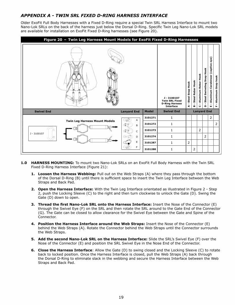
APPENDIX A - TWIN SRL FIXED D-RING HARNESS INTERFACE
Older ExoFit Full Body Harnesses with a Fixed D-Ring require a special Twin SRL Harness Interface to mount two Nano-Lok SRLs on the back of the harness just below the Dorsal D-Ring. Specifi c Twin Leg Nano-Lok SRL models are available for installation on ExoFit Fixed D-Ring harnesses (see Figure 20).
Figure 20 – Twin Leg Harness Mount Models for ExoFit Fixed D-Ring Harnesses
J - 3100107Twin SRL Fixed D-Ring Harness
Interface A -
Ste
el
Sn
ap
Ho
ok
B -
Ste
el
Reb
ar
Ho
ok
C -
Alu
min
um
Reb
ar
Ho
ok
D -
Ste
el
Sw
iveli
ng
Sn
ap
Ho
ok
E -
Alu
min
um
Cara
bin
eer
(cap
tive e
ye)
F -
Alu
min
um
Sn
ap
ho
ok
Swivel End Lanyard End Model Swivel End Lanyard End
J - 3100107
Twin Leg Harness Mount Models A
B
C
D
E
F
3101271 1 2
3101272 1 2
3101273 1 2
3101274 1 2
3101287 1 2
3101288 1 2
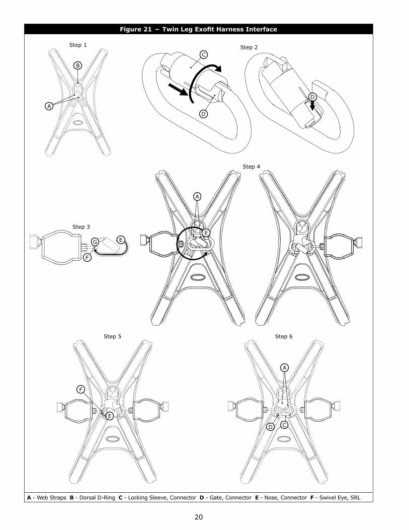
1.0 HARNESS MOUNTING: To mount two Nano-Lok SRLs on an ExoFit Full Body Harness with the Twin SRL Fixed D-Ring Harness Interface (Figure 21):
1. Loosen the Harness Webbing: Pull out on the Web Straps (A) where they pass through the bottom of the Dorsal D-Ring (B) until there is suffi cient space to insert the Twin Leg Interface between the Web Straps and Back Pad.
2. Open the Harness Interface: With the Twin Leg Interface orientated as illustrated in Figure 2 - Step 2, push the Locking Sleeve (C) to the right and then turn clockwise to unlock the Gate (D). Swing the Gate (D) down to open.
3. Thread the fi rst Nano-Lok SRL onto the Harness Interface: Insert the Nose of the Connector (E) through the Swivel Eye (F) on the SRL and then rotate the SRL around to the Gate End of the Connector (G). The Gate can be closed to allow clearance for the Swivel Eye between the Gate and Spine of the Connector.
4. Position the Harness Interface around the Web Straps: Insert the Nose of the Connector (E) behind the Web Straps (A). Rotate the Connector behind the Web Straps until the Connector surrounds the Web Straps.
5. Add the second Nano-Lok SRL on the Harness Interface: Slide the SRL’s Swivel Eye (F) over the Nose of the Connector (E) and position the SRL Swivel Eye in the Nose End of the Connector.
6. Close the Harness Interface: Allow the Gate (D) to swing closed and the Locking Sleeve (C) to rotate back to locked position. Once the Harness Interface is closed, pull the Web Straps (A) back through the Dorsal D-Ring to eliminate slack in the webbing and secure the Harness Interface between the Web Straps and Back Pad.
20
Figure 21 – Twin Leg Exofi t Harness Interface
Step 1
A
B
Step 2C
D
D
Step 3
EG
F
Step 4
A
E
Step 5
E
F
Step 6
D C
A
A - Web Straps B - Dorsal D-Ring C - Locking Sleeve, Connector D - Gate, Connector E - Nose, Connector F - Swivel Eye, SRL

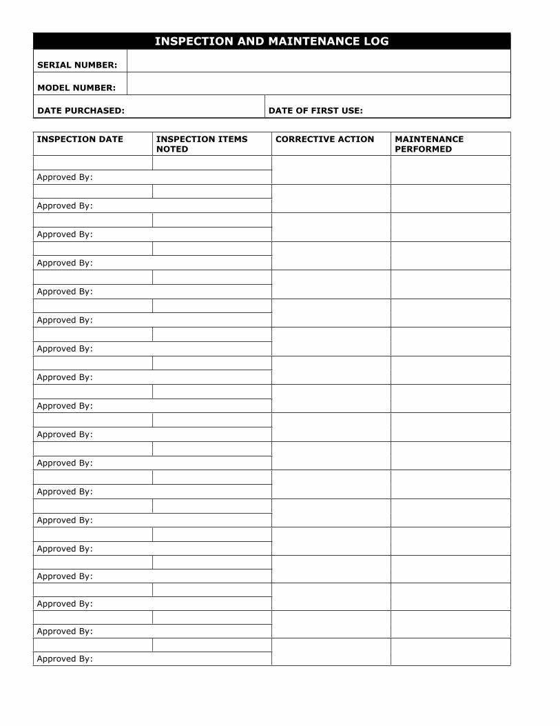
INSPECTION AND MAINTENANCE LOG
SERIAL NUMBER:
MODEL NUMBER:
DATE PURCHASED: DATE OF FIRST USE:
INSPECTION DATE INSPECTION ITEMS NOTED
CORRECTIVE ACTION MAINTENANCE PERFORMED
Approved By:
Approved By:
Approved By:
Approved By:
Approved By:
Approved By:
Approved By:
Approved By:
Approved By:
Approved By:
Approved By:
Approved By:
Approved By:
Approved By:
Approved By:
Approved By:
Approved By:
Approved By:

LIMITED LIFETIME WARRANTY
Warranty to End User: D B Industries, Inc., dba CAPITAL SAFETY USA (“CAPITAL SAFETY”) warrants to the original end user (“End User”) that its products are free from defects in materials and workmanship under normal use and service. This warranty extends for the lifetime of the product from the date the product is purchased by the End User, in new and unused condition, from a CAPITAL SAFETY authorized distributor. CAPITAL SAFETY’S entire liability to End User and End User’s exclusive remedy under this warranty is limited to the repair or replacement in kind of any defective product within its lifetime (as CAPITAL SAFETY in its sole discretion determines and deems appropriate). No oral or written information or advice given by CAPITAL SAFETY, its distributors, directors, offi cers, agents or employees shall create any different or additional warranties or in any way increase the scope of this warranty. CAPITAL SAFETY will not accept liability for defects that are the result of product abuse, misuse, alteration or modifi cation, or for defects that are due to a failure to install, maintain, or use the product in accordance with the manufacturer’s instructions.
CAPITAL SAFETY’S WARRANTY APPLIES ONLY TO THE END USER. THIS WARRANTY IS THE ONLY WARRANTY APPLICABLE TO OUR PRODUCTS AND IS IN LIEU OF ALL OTHER WARRANTIES AND LIABILITIES, EXPRESSED OR IMPLIED. CAPITAL SAFETY EXPRESSLY EXCLUDES AND DISCLAIMS ANY IMPLIED WARRANTIES OF MERCHANTABILITY OR FITNESS FOR A PARTICULAR PURPOSE, AND SHALL NOT BE LIABLE FOR INCIDENTAL, PUNITIVE OR CONSEQUENTIAL DAMAGES OF ANY NATURE, INCLUDING WITHOUT LIMITATION, LOST PROFITS, REVENUES, OR PRODUCTIVITY, OR FOR BODILY INJURY OR DEATH OR LOSS OR DAMAGE TO PROPERTY, UNDER ANY THEORY OF LIABILITY, INCLUDING WITHOUT LIMITATION, CONTRACT, WARRANTY, STRICT LIABILITY, TORT (INCLUDING NEGLIGENCE) OR OTHER LEGAL OR EQUITABLE THEORY.
GARANTÍA LIMITADA DE POR VIDAGarantía para el usuario fi nal: D B Industries, Inc., que opera bajo el nombre de CAPITAL SAFETY USA (“CAPITAL SAFETY”) garantiza al usuario fi nal original (“Usuario fi nal”) que sus productos están libres de defectos de materiales y de mano de obra en condiciones normales de uso y mantenimiento. Esta garantía se extiende durante la vida útil del producto a partir de la fecha en que el Usuario fi nal adquiere el producto, nuevo y sin uso, a un distribuidor autorizado de CAPITAL SAFETY. La entera responsabilidad de CAPITAL SAFETY hacia el Usuario fi nal y el remedio exclusivo para el Usuario fi nal bajo esta garantía están limitados a la reparación o el reemplazo por materiales de todo producto defectuoso dentro de su vida útil (según CAPITAL SAFETY lo determine y considere apropiado a su solo criterio). Ninguna información o asesoramiento, oral o escrito, proporcionado por CAPITAL SAFETY, sus distribuidores, directores, funcionarios, agentes o empleados creará una garantía diferente o adicional ni aumentará de ninguna manera el alcance de esta garantía. CAPITAL SAFETY no aceptará responsabilidad por defectos resultantes del abuso, el uso incorrecto, la alteración o la modifi cación del producto, ni por defectos resultantes de no respetar las instrucciones del fabricante durante la instalación, el mantenimiento o el uso del producto.
LA GARANTÍA DE CAPITAL SAFETY SE APLICA ÚNICAMENTE AL USUARIO FINAL. ESTA GARANTÍA ES LA ÚNICA GARANTÍA QUE SE APLICA A NUESTROS PRODUCTOS Y REEMPLAZA A TODAS LAS OTRAS GARANTÍAS Y RESPONSABILIDADES, EXPRESAS O IMPLÍCITAS. CAPITAL SAFETY EXPRESAMENTE EXCLUYE Y RENUNCIA A TODAS LAS GARANTÍAS IMPLÍCITAS DE COMERCIABILIDAD O APTITUD PARA UN PROPÓSITO PARTICULAR, Y NO SERÁ RESPONSABLE POR DAÑOS INCIDENTALES, PUNITIVOS O EMERGENTES DE NINGUNA NATURALEZA, INCLUYENDO SIN LIMITACIÓN PÉRDIDAS DE INGRESOS, GANANCIAS O PRODUCTIVIDAD; NI POR LESIONES CORPORALES O MUERTE, O PÉRDIDA DE O DAÑO A LA PROPIEDAD, BAJO CUALQUIER TEORÍA DE RESPONSABILIDAD, INCLUYENDO SIN LIMITACIÓN CONTRATO, GARANTÍA, RESPONSABILIDAD ESTRICTA, AGRAVIO (INCLUIDA NEGLIGENCIA) O CUALQUIER OTRA TEORÍA LEGAL O EQUITATIVA.
Certificate No. FM 39709
I S O9001
A Capital Safety Company
CSG USA & Latin America3833 SALA Way Red Wing, MN 55066-5005 Toll Free: 800.328.6146Phone: 651.388.8282Fax: [email protected]
CSG Canada260 Export Boulevard Mississauga, ON L5S 1Y9 Phone: 905.795.9333 Toll-Free: 800.387.7484 Fax: 888.387.7484 [email protected]
CSG Northern Europe5a Merse RoadNorth Moons, MoatReditch, Worcestershire, UKB98 9HLPhone: + 44 (0)1527 548 000Fax: + 44 (0)1527 591 [email protected]
CSG EMEA(Europe, Middle East, Africa)Le Broc CenterZ.I. 1ère Avenue5600 M B.P. 15 06511CarrosLe Broc CedexFrancePhone: + 33 4 97 10 00 10Fax: + 33 4 93 08 79 [email protected]
CSG Australia & New Zealand95 Derby StreetSilverwaterSydney NSW 2128AUSTRALIAPhone: +(61) 2 8753 7600Toll-Free : 1 800 245 002 (AUS)Toll-Free : 0800 212 505 (NZ) Fax: +(61) 2 87853 7603 [email protected]
CSG AsiaSingapore:16S, Enterprise Road Singapore 627666Phone: +65 - 65587758Fax: +65 - [email protected]
Shanghai:Rm 1406, China Venturetech Plaza819 Nan Jing Xi Rd,Shanghai 200041, P R ChinaPhone: +86 21 62539050Fax: +86 21 62539060
www.capitalsafety.com