Instruction Manual - Schäfter · GenApi: for configuring the camera Standard Feature Naming...
38
© 2018-04 E [email protected] www.SuKHamburg.com Instruction Manual SK6288VKOC-L shared_Titel_ML.indd SK6288VKOC-L Color Line Scan Camera 3x 2096 pixels 14 x 14 µm², line frequency up to 9.26 kHz Instruction Manual SK6288VKOC-L 3 2 Sample Configuration 1 CCD line scan camera SK6288VKOC-L mounted with 2 Mounting bracket SK5105-L 3 Clamping claws SK5101 4 Focus adapter FA22R-45 (two-piece), facilitates adjustment of any rotation angle 5 Enlarging lens Apo-Rodagon N 4.0/80 5 4 1 color
Transcript of Instruction Manual - Schäfter · GenApi: for configuring the camera Standard Feature Naming...
© 2018-04 E [email protected] www.SuKHamburg.com
Inst
ruct
ion
Man
ual S
K62
88V
KO
C-L
shar
ed_T
itel_
ML.
ind
d
SK6288VKOC-LColor Line Scan Camera3x 2096 pixels 14 x 14 µm², line frequency up to 9.26 kHz
Instruction Manual
SK6288VKOC-L
3
2
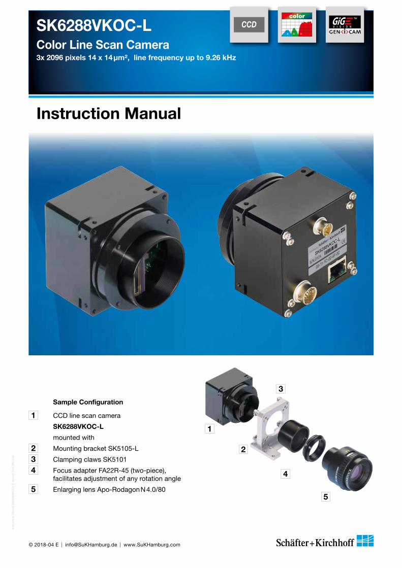
Sample Configuration
1 CCD line scan camera
SK6288VKOC-L
mounted with
2 Mounting bracket SK5105-L
3 Clamping claws SK5101
4 Focus adapter FA22R-45 (two-piece), facilitates adjustment of any rotation angle
5 Enlarging lens Apo-Rodagon N 4.0/805
4
1
400 500 700 800600Wavelength (nm)
0
Res
pon
sitiv
ity(V
/mJ/
cm2)
100
0.0
1.0
400 500 600Wavelength (nm)
Rel
ativ
e se
nsitv
ity
color

Inst
ruct
ion
Man
ual S
K62
88V
KO
C-L
shar
ed_H
inw
eise
.ind
d
2
Instruction Manual SK6288VKOC-L © 2018-04 E
How to Use this Instruction Manual
Electricity Warning
Assembly and initial operation of the line scan camera must be carried out under dry conditions.
Do not operate the camera if you notice any condensation or moisture in order to avoid danger of a short circuit or static discharge!
Risk of High Power Lighting
According to the application, laser or high power LED light sources might be used. These can affect your eyesight temporarily or even cause permanent damage to the eyes or skin.
Do not look directly into the light beam!w
Mechanics Warning
Ensure that the motion device and the scan way is free to move and that no obstacles are in the way.
Do not place any part of the body in the way of moving parts!
Line scan cameras are mostly used in combination with a motion device such as a translation stage, a conveyer or a rotational drive, as well as with high intensity light sources.
For assembly close down these devices whenever possible. Beyond that, please consider the following warnings:
Safety Warnings
Please read the following sections of this Instruction Manual before unpacking, assembly or use of the Line Camera System:
The safety warnings on this page
Introduction to the system, page 4
Assembly and initial setup, page 6
Keep this Instruction Manual in a safe place for future reference.
!

In
stru
ctio
n M
anua
l SK
6288
VK
OC
-L
sh
ared
_Co
nten
ts.in
dd
3
Instruction Manual SK6288VKOC-L © 2018-04 E
Contents
How to Use this Instruction Manual 2
Safety Warnings 2
Contents 3
1 Introducing the SK6288VKOC-L Line Scan Camera � ��������������������������������������������� 4
1.1 Intended Purpose and Overview 4
1.2 System Setup at a Glance 5
1.3 Computer System Requirements 6
1.4 SK6288VKOC-L Line Scan Camera - Specifications 6
2 Installation and Setup �������������������������������������������������������������������������������� 7
2.1 Mechanical Installation: Mounting Options and Dimensions 7
2.2 Electrical Installation: Connections and I/O Signals 8
2.3 GigE Connections and Software Installation 9GigE Network Integration for Standard GigE Network Adapters
2.4 SkLineScan Software Installation (Optional) 11SkLineScan InstallationSkLineScan Start-upCamera SetupInitial Function Test
3 Camera Control and Performing a Scan � �������������������������������������������������������� 12
3.1 Software: SkLineScan 12Function Overview: SkLineScan ToolbarBasic Visualization of the Sensor Output
3.2 Adjustments for Optimum Scan Results 14Lens FocussingSensor AlignmentGain/Offset AdjustmentWhite Balance and Shading CorrectionIntegration TimeSynchronization of the Imaging Procedure and the Object Scan VelocitySynchronization ModesRGB Sensors: 2D Imaging and Pixel Allocation
3.3 GigE Vision Device Feature List (Gen<i>Cam compliant) 24
4 Advanced SkLineScan Software Functions ������������������������������������������������������ 26
4.1 Camera Control by Commands 26Set CommandsRequest Commands
4.2 Advanced Synchronization Control 28Advanced Trigger Functions and Sync Control Register SettingsExample Timing Diagrams of Advanced Synchronization Control
5 Sensor Information ��������������������������������������������������������������������������������� 30
Glossary 34
CE-Conformity 37
Warranty 37
Accessories 38
Introducing the SK6288VKOC-L Line Scan Camera
Inst
ruct
ion
Man
ual S
K62
88V
KO
C-L
shar
ed_I
ntro
duc
tion_
Gig
EV
_ML.
ind
d
4
Instruction Manual SK6288VKOC-L © 2018-04 E
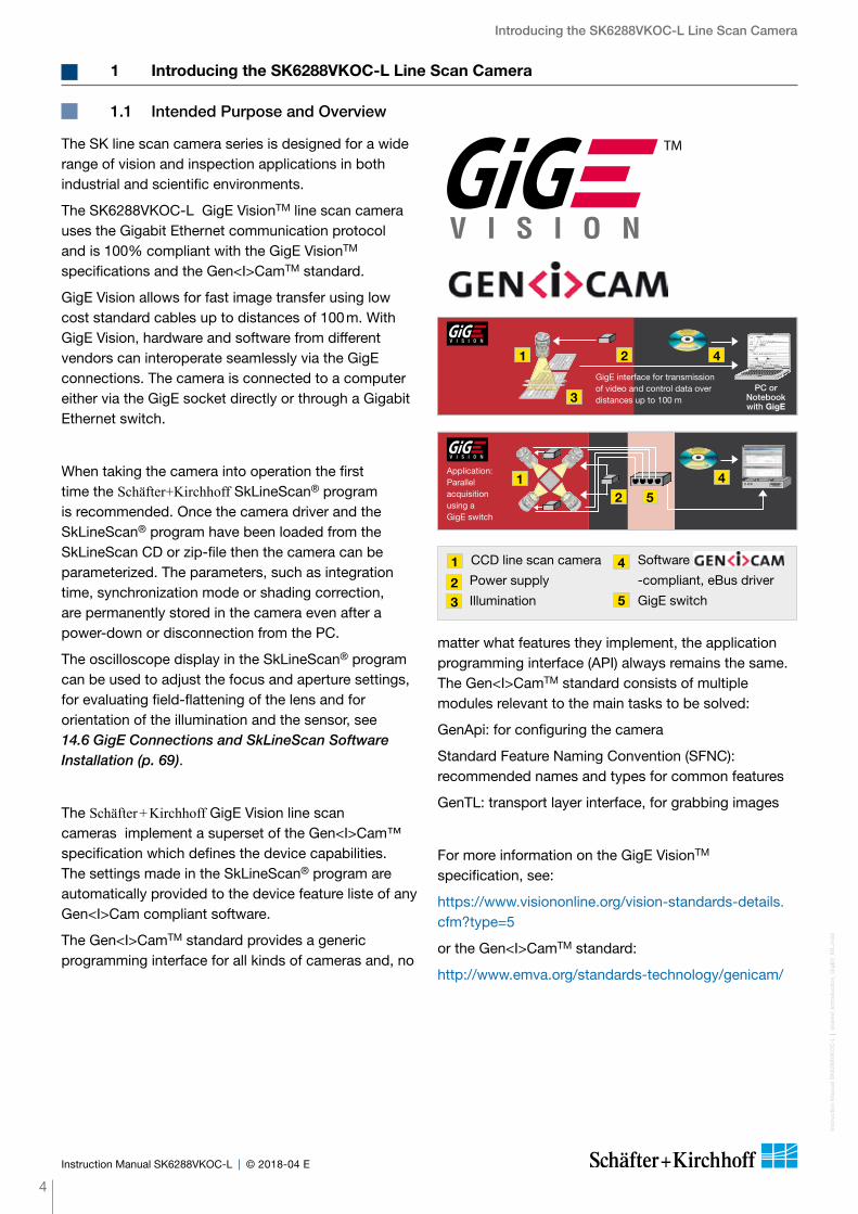
The SK line scan camera series is designed for a wide range of vision and inspection applications in both industrial and scientific environments.
The SK6288VKOC-L GigE VisionTM line scan camera uses the Gigabit Ethernet communication protocol and is 100% compliant with the GigE VisionTM specifications and the Gen<I>CamTM standard.
GigE Vision allows for fast image transfer using low cost standard cables up to distances of 100 m. With GigE Vision, hardware and software from different vendors can interoperate seamlessly via the GigE connections. The camera is connected to a computer either via the GigE socket directly or through a Gigabit Ethernet switch.
When taking the camera into operation the first time the Schäfter+Kirchhoff SkLineScan® program is recommended. Once the camera driver and the SkLineScan® program have been loaded from the SkLineScan CD or zip-file then the camera can be parameterized. The parameters, such as integration time, synchronization mode or shading correction, are permanently stored in the camera even after a power-down or disconnection from the PC.
The oscilloscope display in the SkLineScan® program can be used to adjust the focus and aperture settings, for evaluating field-flattening of the lens and for orientation of the illumination and the sensor, see 14.6 GigE Connections and SkLineScan Software Installation (p. 69).
The Schäfter + Kirchhoff GigE Vision line scan cameras implement a superset of the Gen<I>Cam™ specification which defines the device capabilities. The settings made in the SkLineScan® program are automatically provided to the device feature liste of any Gen<I>Cam compliant software.
The Gen<I>CamTM standard provides a generic programming interface for all kinds of cameras and, no
matter what features they implement, the application programming interface (API) always remains the same. The Gen<I>CamTM standard consists of multiple modules relevant to the main tasks to be solved:
GenApi: for configuring the camera
Standard Feature Naming Convention (SFNC): recommended names and types for common features
GenTL: transport layer interface, for grabbing images
For more information on the GigE VisionTM specification, see:
https://www.visiononline.org/vision-standards-details.cfm?type=5
or the Gen<I>CamTM standard:
http://www.emva.org/standards-technology/genicam/
1 Introducing the SK6288VKOC-L Line Scan Camera
1.1 Intended Purpose and Overview
CCD line scan camera
2 Power supply
3 Illumination
Software Gen<i>Cam
-compliant, eBus driver
GigE switch
1 4
5
PC or Notebookwith GigE
GigE inter face for transmission of video and control data over distances up to 100 m
421
3
Application:Parallel acquisition using a GigE switch
4
21
5

Introducing the SK6288VKOC-L Line Scan CameraIn
stru
ctio
n M
anua
l SK
6288
VK
OC
-L
sh
ared
_Int
rod
uctio
n_G
igE
V_M
L.in
dd
5
Instruction Manual SK6288VKOC-L © 2018-04 E
1.2 System Setup at a Glance
red: SK6288VKOC-L scope of deliveryblue: accessories for minimum system configurationblack: optional accessories
For accessory order details see Accessories (p. 38).
Motion unit with encoder
Synchronization cable
Power supply cable
Gigabit Ethernet cable
Computer
Power supply unit
Schäfter�+�Kirchhoff SkLineScan® adjustment and control software
3rd party software that supports the GEN<i>CAMTM standard
Line scan camera
Clamping claw
Mounting bracket
Optics (e. g. lens, focus adapter, tube extension ring)

Sensor category CCD Color Sensor
Sensor type KLI2113
Pixel number 3x 2096
Pixel size (width x height) 14 x 14 µm2
Pixel spacing 14 µm
Line spacing, line sequence 112 µm, blue (B) - green (G) - red (R)
Active sensor length 29.3 mm
Anti-blooming -
Integration control x
Shading correction x
Line synchronization modes Line Sync, Line Start, Exposure Start, Exposure Active
Frame synchronization x
Pixel frequency 60 / 30 MHz
Maximum line frequency 9.26 kHz
Integration time 0.01 ... 20 ms
Dynamic range 1:2500 (rms)
Spectral range 400 ... 700 nm
Video signal color 3*8 Bit digital
Interface GigE Vision
Voltage +5V, +15V
Power consumption 4.3 W
Casing 65 mm x 65 mm x 72.4 mm (Case type BG3)
Objective mount M45x0.75
Flange focal length 19.5 mm
Weight 0.3 kg
Operating temperature +5 ... +45°C
Introduction
Inst
ruct
ion
Man
ual S
K62
88V
KO
C-L
shar
ed_S
yste
mR
equi
rem
ents
_Sp
ecs_
ML.
ind
d
6
Instruction Manual SK6288VKOC-L © 2018-04 E
1.3 Computer System Requirements
1.4 SK6288VKOC-L Line Scan Camera - Specifications
Intr
oduc
tion
• Intel Pentium Dual Core or AMD equivalent
• RAM min. 4 GB, depending on size of acquired images
• High-performance video card, PCIe bus
• Operating Systems: Windows 7 / 8.1 / 10 (64 or 32-bit) or Linux kernel 3.13 or higher
• CD/DVD drive for software installation.
Network Adapter:
• Any Gigabit Ethernet network adapter as a card or on the motherboard is suitable. For the best performance, a network interface card (NIC) with Intel PRO/1000 chip is recommended.
• PCIe adapters outperform PCI adapters.
• Network adapters that support Jumbo Frames outperform adapters with fixed packet-size frames.

Installation and SetupIn
stru
ctio
n M
anua
l SK
6288
VK
OC
-L
sh
ared
_Ins
talla
tion-
Mec
hani
c_A
xx-B
Gx_
ML.
ind
d
7
Instruction Manual SK6288VKOC-L © 2018-04 E
2 Installation and Setup
2.1 Mechanical Installation: Mounting Options and Dimensions
Casing type BG3
Mounting Options
• The best fixing point of the camera is the collar for the mounting bracket SK5105-L (available as an accessory).
• Four threaded holes M3 x 6.5 mm provide further options for customized brackets.
• The length and weight of the optics might be beyond the capability of the standard mounting bracket SK5105-L. For this purpose, a second mounting bracket type SK5105-2L to hold the tube extension ring(s) is more appropriate.
Optics Handling
• If the camera and the optics are ordered as a kit, the components are pre-assembled and shipped as one unit. Keep the protective cap on the lens until the mechanical installation is finished.
• If you must expose the sensor or lens surface, ensure the environment is as dust-free as possible.
• Gently blow off loose particles using clean compressed air.
• The sensor and lens surfaces can be cleaned with a soft tissue moistened with water or a water-based glass cleaner.
Mounting bracket SK5105-L
Mounting system SK5105-2L
for cameras with a tube extension > 52 mm
Clamping set SK5101
Set of 4 pcs. clamping claws incl. screws
66
1010
36M3 Ø3.3
6
50.3
41.7
Ø 47.5
5020 16.5 3.56.5
Ø4.3
15M4
1/4’
’ 20G
40 63 70
6
36
Ø 47.5
703.5 31.5 25 10
3.5
70 63 40
1/4’
’ 20G
M4 Ø4.3
Hex socket head screwDIN 912–M3x12
Clamping claw
65
72.4
2.56
4 25.1
FFL
Ø65
Ø47
.5
50/M
3/4x
90°
12.7Pixel 1
M3 (4x)depth 6.5 mm
65
M45x0.75
58 41.7
BG3 Lens mount: M45x0.75Seat for bracket: Ø47.5 mmFlange focal length: FFL = 19.5 mm
CCD-Sensor
3
1
2
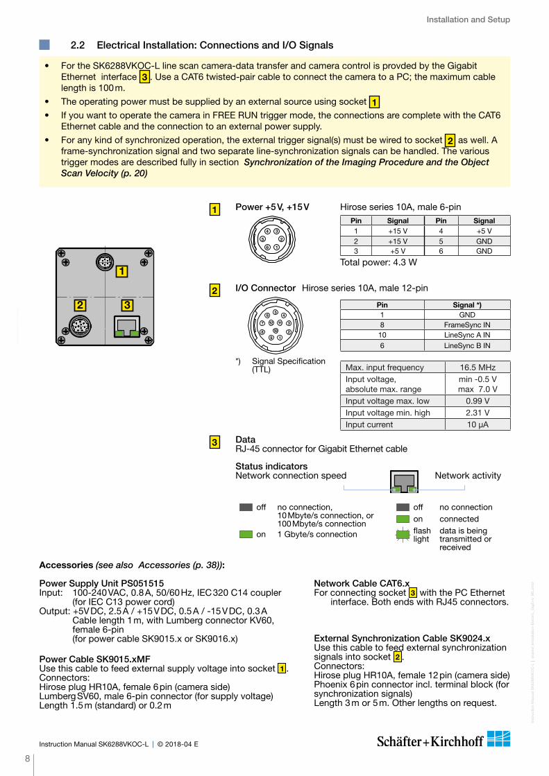
1 Power +5 V, +15 V Hirose series 10A, male 6-pin
Total power: 4.3 W
Pin Signal Pin Signal1 +15 V 4 +5 V2 +15 V 5 GND3 +5 V 6 GND2
1
3
45
6
7
89
10
11122
1
34
5
6
Power Cable SK9015.xMFUse this cable to feed external supply voltage into socket 1 .Connectors:Hirose plug HR10A, female 6 pin (camera side)Lumberg SV60, male 6-pin connector (for supply voltage)Length 1.5 m (standard) or 0.2 m
Power Supply Unit PS051515Input: 100-240 VAC, 0.8 A, 50/60 Hz, IEC 320 C14 coupler
(for IEC C13 power cord)Output: +5V DC, 2.5 A / +15 V DC, 0.5 A / -15 V DC, 0.3 A
Cable length 1 m, with Lumberg connector KV60, female 6-pin (for power cable SK9015.x or SK9016.x)
Installation and Setup
Inst
ruct
ion
Man
ual S
K62
88V
KO
C-L
shar
ed_I
nsta
llatio
n-E
lect
ric_
Gig
E+
V_M
L.in
dd
8
Instruction Manual SK6288VKOC-L © 2018-04 E
2.2 Electrical Installation: Connections and I/O Signals
External Synchronization Cable SK9024.xUse this cable to feed external synchronization signals into socket 2 .Connectors:Hirose plug HR10A, female 12 pin (camera side)Phoenix 6 pin connector incl. terminal block (for synchronization signals)Length 3 m or 5 m. Other lengths on request.
Network Cable CAT6.xFor connecting socket 3 with the PC Ethernet
interface. Both ends with RJ45 connectors.
• For the SK6288VKOC-L line scan camera-data transfer and camera control is provded by the Gigabit Ethernet interface 3 . Use a CAT6 twisted-pair cable to connect the camera to a PC; the maximum cable length is 100 m.
• The operating power must be supplied by an external source using socket 1• If you want to operate the camera in FREE RUN trigger mode, the connections are complete with the CAT6
Ethernet cable and the connection to an external power supply.
• For any kind of synchronized operation, the external trigger signal(s) must be wired to socket 2 as well. A frame-synchronization signal and two separate line-synchronization signals can be handled. The various trigger modes are described fully in section Synchronization of the Imaging Procedure and the Object Scan Velocity (p. 20)
21
3
45
6
7
89
10
11122
1
34
5
6
Pin Signal *)1 GND8 FrameSync IN10 LineSync A IN6 LineSync B IN
2 I/O Connector Hirose series 10A, male 12-pin
*) Signal Specification (TTL) Max. input frequency 16.5 MHz
Input voltage, absolute max. range
min -0.5 Vmax 7.0 V
Input voltage max. low 0.99 VInput voltage min. high 2.31 VInput current 10 µA
Inst
alla
tion
and
Set
up
3 DataRJ-45 con nector for Gigabit Ethernet cable
Status indicatorsNetwork connection speed Network activity
off no connection, 10 Mbyte/s connection, or 100 Mbyte/s connection
on 1 Gbyte/s connection
off no connectionon connectedflash light
data is being transmitted or received
Accessories (see also Accessories (p. 38)):
Installation and Setup
9
Inst
ruct
ion
Man
ual S
K62
88V
KO
C-L
shar
ed_I
nsta
llatio
n-S
oft
war
e_G
igE
V.in
dd
Instruction Manual SK6288VKOC-L © 2018-04 E
Inst
alla
tion
and
Set
up
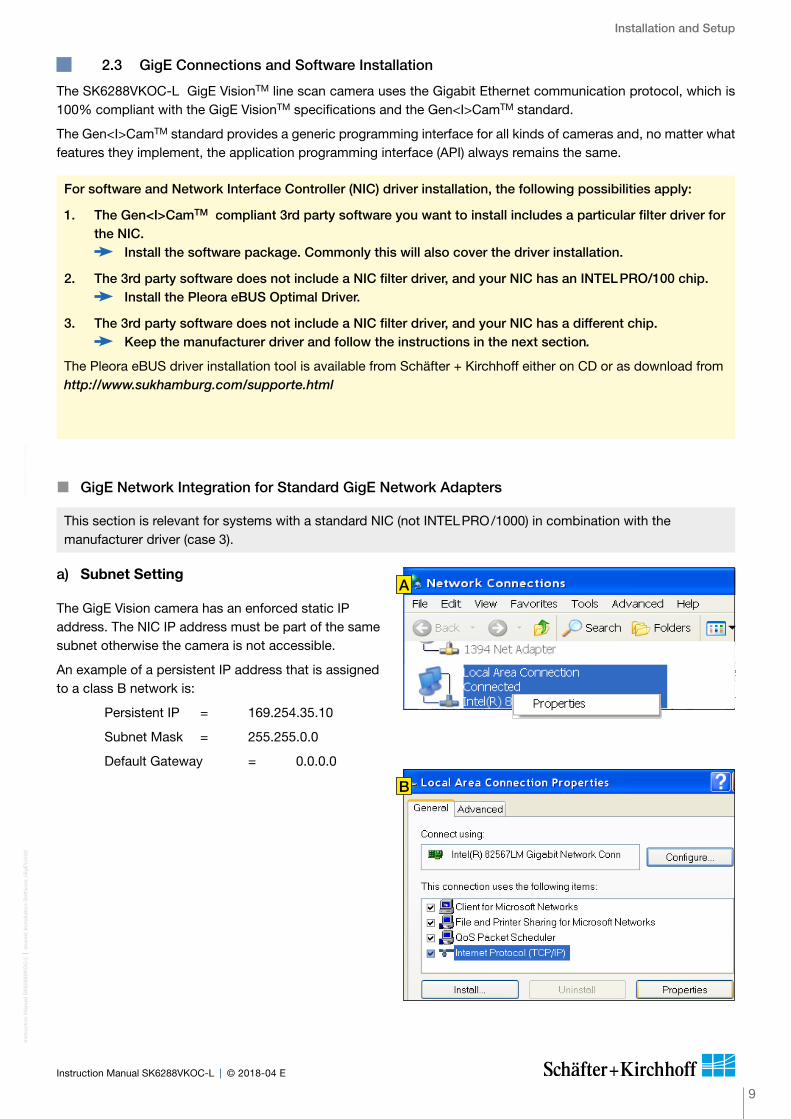
2.3 GigE Connections and Software Installation
� GigE Network Integration for Standard GigE Network Adapters
The SK6288VKOC-L GigE VisionTM line scan camera uses the Gigabit Ethernet communication protocol, which is 100% compliant with the GigE VisionTM specifications and the Gen<I>CamTM standard.
The Gen<I>CamTM standard provides a generic programming interface for all kinds of cameras and, no matter what features they implement, the application programming interface (API) always remains the same.
For software and Network Interface Controller (NIC) driver installation, the following possibilities apply:
1. The Gen<I>CamTM compliant 3rd party software you want to install includes a particular filter driver for the NIC.
Install the software package. Commonly this will also cover the driver installation.
2. The 3rd party software does not include a NIC filter driver, and your NIC has an INTEL PRO/100 chip. Install the Pleora eBUS Optimal Driver.
3. The 3rd party software does not include a NIC filter driver, and your NIC has a different chip. Keep the manufacturer driver and follow the instructions in the next section.
The Pleora eBUS driver installation tool is available from Schäfter + Kirchhoff either on CD or as download from http://www.sukhamburg.com/supporte.html
a) Subnet Setting
The GigE Vision camera has an enforced static IP address. The NIC IP address must be part of the same subnet otherwise the camera is not accessible.
An example of a persistent IP address that is assigned to a class B network is:
Persistent IP = 169.254.35.10
Subnet Mask = 255.255.0.0
Default Gateway = 0.0.0.0
This section is relevant for systems with a standard NIC (not INTEL PRO /1000) in combination with the manufacturer driver (case 3).
B
A
Installation and Setup
Inst
ruct
ion
Man
ual S
K62
88V
KO
C-L
shar
ed_I
nsta
llatio
n-S
oft
war
e_G
igE
V.in
dd
10
Instruction Manual SK6288VKOC-L © 2018-04 E
b) Windows Firewall
a) Switch off the Windows Firewall or
b) Allow an exception:
Start > Control Panel > Open the Windows Firewall
Select the Exceptions tab
Click Add Program
The "Add a Program" dialog appears
Select the camera control program and click "OK"
Click "OK" to close the Windows Firewall dialog
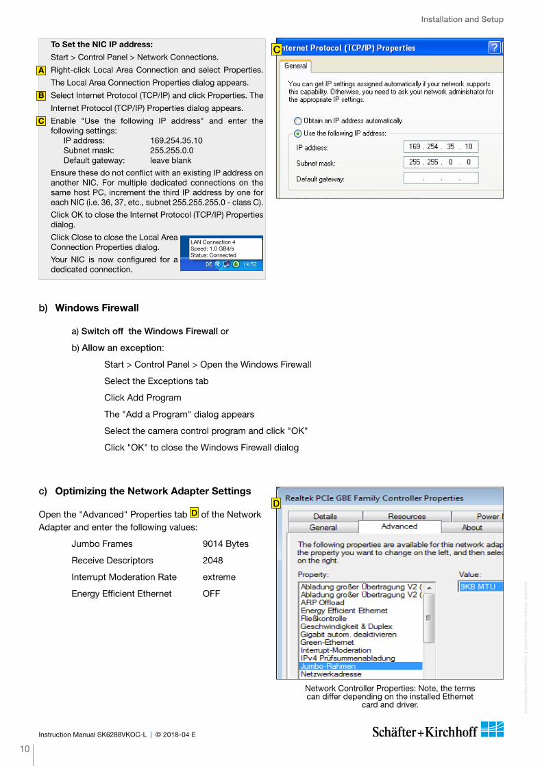
c) Optimizing the Network Adapter Settings
Open the "Advanced" Properties tab D of the Network Adapter and enter the following values:
Jumbo Frames 9014 Bytes
Receive Descriptors 2048
Interrupt Moderation Rate extreme
Energy Efficient Ethernet OFF
Network Controller Properties: Note, the terms can differ depending on the installed Ethernet
card and driver.
D
CTo Set the NIC IP address:
Start > Control Panel > Network Connections.
Right-click Local Area Connection and select Properties.
The Local Area Connection Properties dialog appears.
Select Internet Protocol (TCP/IP) and click Properties. The
Internet Protocol (TCP/IP) Properties dialog appears.
Enable "Use the following IP address" and enter the following settings: IP address: 169.254.35.10 Subnet mask: 255.255.0.0 Default gateway: leave blank
Ensure these do not conflict with an existing IP address on another NIC. For multiple dedicated connections on the same host PC, increment the third IP address by one for each NIC (i.e. 36, 37, etc., subnet 255.255.255.0 - class C).
Click OK to close the Internet Protocol (TCP/IP) Properties dialog.
Click Close to close the Local Area Connection Properties dialog.
Your NIC is now configured for a dedicated connection.
A
B
C
LAN Connection 4Speed: 1.0 GBit/sStatus: Connected
Installation and Setup
11
Inst
ruct
ion
Man
ual S
K62
88V
KO
C-L
shar
ed_I
nsta
llatio
n-S
oft
war
e_G
igE
V.in
dd
Instruction Manual SK6288VKOC-L © 2018-04 E
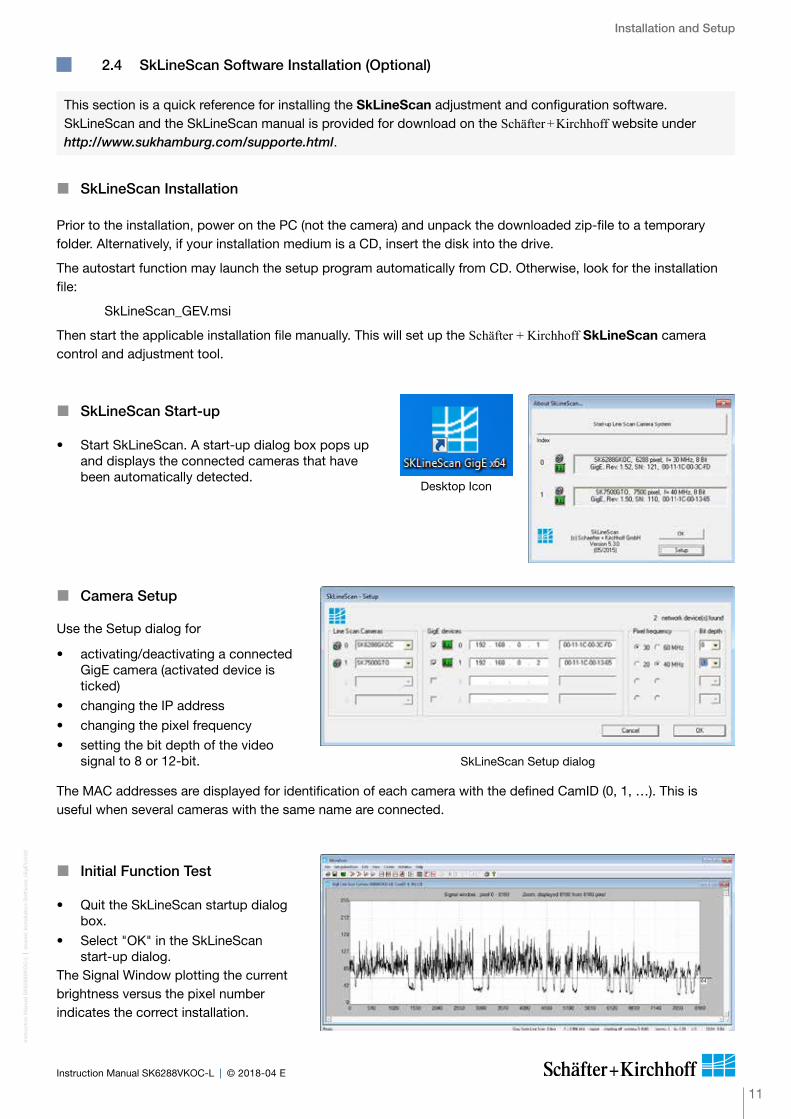
� Initial Function Test
• Quit the SkLineScan startup dialog box.
• Select "OK" in the SkLineScan start-up dialog.
The Signal Window plotting the current brightness versus the pixel number indicates the correct installation.
� Camera Setup
Use the Setup dialog for
• activating/deactivating a connected GigE camera (activated device is ticked)
• changing the IP address
• changing the pixel frequency
• setting the bit depth of the video signal to 8 or 12-bit.
The MAC addresses are displayed for identification of each camera with the defined CamID (0, 1, …). This is useful when several cameras with the same name are connected.
SkLineScan Setup dialog
� SkLineScan Start-up
• Start SkLineScan. A start-up dialog box pops up and displays the connected cameras that have been automatically detected.
Desktop Icon
2.4 SkLineScan Software Installation (Optional)
� SkLineScan Installation
Prior to the installation, power on the PC (not the camera) and unpack the downloaded zip-file to a temporary folder. Alternatively, if your installation medium is a CD, insert the disk into the drive.
The autostart function may launch the setup program automatically from CD. Otherwise, look for the installation file:
SkLineScan_GEV.msi
Then start the applicable installation file manually. This will set up the Schäfter + Kirchhoff SkLineScan camera control and adjustment tool.
This section is a quick reference for installing the SkLineScan adjustment and configuration software. SkLineScan and the SkLineScan manual is provided for download on the Schäfter + Kirchhoff website under http://www.sukhamburg.com/supporte.html.

Camera Control and Performing a Scan
Inst
ruct
ion
Man
ual S
K62
88V
KO
C-L
shar
ed_C
amer
aCo
ntro
l(1)_
SkL
ineS
can_
ML.
ind
d
12
Instruction Manual SK6288VKOC-L © 2018-04 E
3 Camera Control and Performing a Scan
New line scan. All open "Signal window" windows will be closed. [F2]
"Camera Control" dialog for parameter settings: integration time, line frequency, synchronization mode, thresholding
Zooming in and out
New line scan. "Area Scan" windows will be closed, "Signal window" windows will remain open. [F2]
Threshold mode in new binary signal window.
"Shading Correction" dialog to adjust the white balance [Alt + s]
"Gain/Offset Control" dialog, also for commands input [Shif+F4]
New area scan
For an in-depth guide on how to perform imaging and to use the obtained data using the Schäfter + Kirchhoff software package, see the SkLineScan Software Manual.
The most common functions of the line scan camera can be controlled by menu items and dialog boxes.
Commands controlling comprehensive camera functionality can be entered in the "Camera Gain / Offset Control" dialog.
Click on the desktop icon to start the SkLineScan program.
The SkLineScan program recog nizes the connected line scan cameras automatically. The identified cameras are shown in the start-up dialog A , and the index order corresponds with the individual MAC addresses of the cameras.
If the SK6288VKOC-L camera is identified correctly, confirm with "OK". The "Signal window" graphicaly showing the intensity signals of the sensor pixels (oscilloscope display) will open. It is responsive in real-time and the zoom function can be used to highlight an area of interest. The oscilloscope display is ideally suited for parameterizing the camera, for evaluating object illumination, for focussing the image or for aligning the line scan camera correctly.
3.1 Software: SkLineScan
This section is a brief introduction to the SkLineScan adjustment and configuration software. A more detailed description is provided in the separate SkLineScan manual. The pdf is included in the SkLineScan installation package or is available for download from the Schäfter + Kirchhoff website under http://www.sukhamburg.com/support.html.
� Function Overview: SkLineScan Toolbar
SkLineScan: Toolbar
SkLineScan: Start-up dialog
A
Camera Control and Performing a ScanIn
stru
ctio
n M
anua
l SK
6288
VK
OC
-L
sh
ared
_Cam
eraC
ont
rol(1
)_S
kLin
eSca
n_M
L.in
dd
13
Instruction Manual SK6288VKOC-L © 2018-04 E
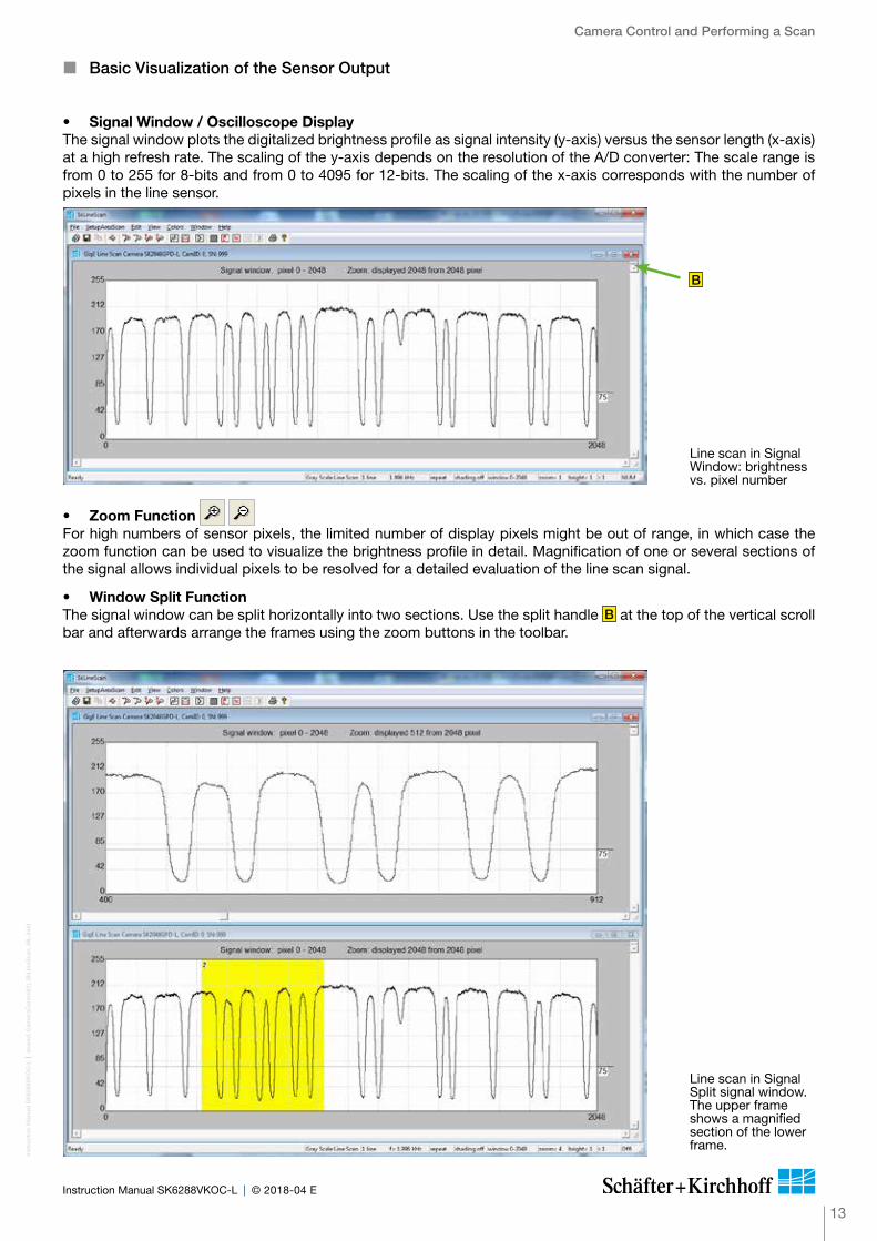
� Basic Visualization of the Sensor Output
• Signal Window / Oscilloscope DisplayThe signal window plots the digitalized brightness profile as signal intensity (y-axis) versus the sensor length (x-axis) at a high refresh rate. The scaling of the y-axis depends on the resolution of the A/D converter: The scale range is from 0 to 255 for 8-bits and from 0 to 4095 for 12-bits. The scaling of the x-axis corresponds with the number of pixels in the line sensor.
• Zoom Function For high numbers of sensor pixels, the limited number of display pixels might be out of range, in which case the zoom function can be used to visualize the brightness profile in detail. Magnification of one or several sections of the signal allows individual pixels to be resolved for a detailed evaluation of the line scan signal.
• Window Split FunctionThe signal window can be split horizontally into two sections. Use the split handle B at the top of the vertical scroll bar and afterwards arrange the frames using the zoom buttons in the toolbar.
Line scan in Signal Window: brightness vs. pixel number
B
Line scan in Signal Split signal window. The upper frame shows a magnified section of the lower frame.
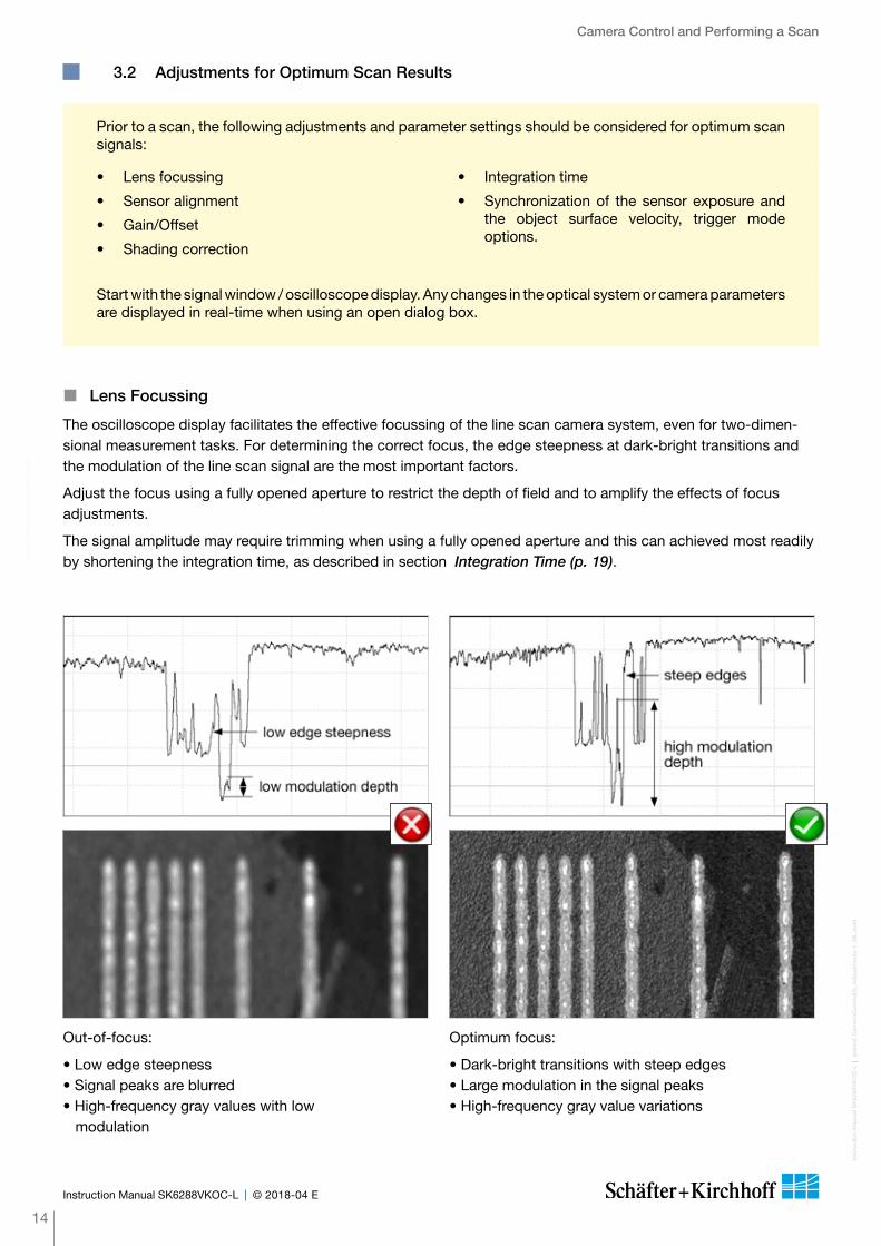
Start with the signal window / oscilloscope display. Any changes in the optical system or camera parameters are displayed in real-time when using an open dialog box.
The oscilloscope display facilitates the effective focussing of the line scan camera system, even for two-dimen-sional measurement tasks. For determining the correct focus, the edge steepness at dark-bright transitions and the modulation of the line scan signal are the most important factors.
Adjust the focus using a fully opened aperture to restrict the depth of field and to amplify the effects of focus adjustments.
The signal amplitude may require trimming when using a fully opened aperture and this can achieved most readily by shortening the integration time, as described in section Integration Time (p. 19).
Camera Control and Performing a Scan
Inst
ruct
ion
Man
ual S
K62
88V
KO
C-L
shar
ed_C
amer
aCo
ntro
l(2)_
Ad
just
men
ts-1
_ML.
ind
d
14
Instruction Manual SK6288VKOC-L © 2018-04 E
• Lens focussing
• Sensor alignment
• Gain/Offset
• Shading correction
• Integration time
• Synchronization of the sensor exposure and the object surface velocity, trigger mode options.
Prior to a scan, the following adjustments and parameter settings should be considered for optimum scan signals:
Out-of-focus:
• Low edge steepness • Signal peaks are blurred • High-frequency gray values with low modulation
Optimum focus:
• Dark-bright transitions with steep edges • Large modulation in the signal peaks • High-frequency gray value variations
3.2 Adjustments for Optimum Scan Results
� Lens Focussing
Cam
era
Con
trol
and
Per
form
ing
a S
can
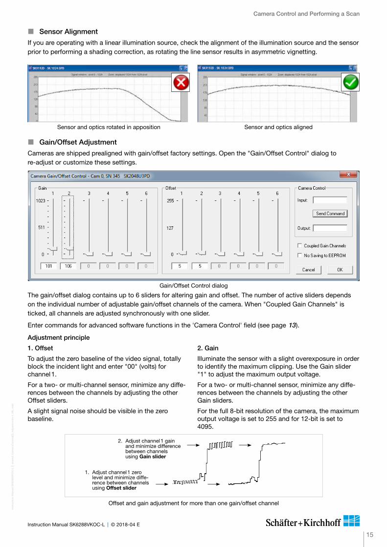
Gain/Offset Control dialog
The gain/offset dialog contains up to 6 sliders for altering gain and offset. The number of active sliders depends on the individual number of adjustable gain/offset channels of the camera. When "Coupled Gain Channels" is ticked, all channels are adjusted synchronously with one slider.
Enter commands for advanced software functions in the 'Camera Control' field (see page 13).
Camera Control and Performing a Scan
15
Inst
ruct
ion
Man
ual S
K62
88V
KO
C-L
shar
ed_C
amer
aCo
ntro
l(2)_
Ad
just
men
ts-1
_ML.
ind
d
Instruction Manual SK6288VKOC-L © 2018-04 E
If you are operating with a linear illumination source, check the alignment of the illumination source and the sensor prior to performing a shading correction, as rotating the line sensor results in asymmetric vignetting.
Sensor and optics rotated in apposition Sensor and optics aligned
Cameras are shipped prealigned with gain/offset factory settings. Open the "Gain/Offset Control" dialog to re-adjust or customize these settings.
Adjustment principle
1. Offset
To adjust the zero baseline of the video signal, totally block the incident light and enter "00" (volts) for channel 1.
For a two- or multi-channel sensor, minimize any diffe-rences between the channels by adjusting the other Offset sliders.
A slight signal noise should be visible in the zero baseline.
2. Gain
Illuminate the sensor with a slight overexposure in order to identify the maximum clipping. Use the Gain slider "1" to adjust the maximum output voltage.
For a two- or multi-channel sensor, minimize any diffe-rences between the channels by adjusting the other Gain sliders.
For the full 8-bit resolution of the camera, the maximum output voltage is set to 255 and for 12-bit is set to 4095.
� Sensor Alignment
� Gain/Offset Adjustment
Offset and gain adjustment for more than one gain/offset channel
2. Adjust channel 1 gain and minimize difference between channels using Gain slider
1. Adjust channel 1 zero level and minimize diffe-rence between channels using Offset slider

Camera Control and Performing a Scan
Inst
ruct
ion
Man
ual S
K62
88V
KO
C-L
shar
ed_C
amer
aCo
ntro
l(2b
)_S
had
ing
Co
rrec
tion_
col.i
ndd
16
Instruction Manual SK6288VKOC-L © 2018-04 E
Shading Correction compensates for non-uniform illumination and lens vignetting, as well as any differences in pixel sensitivity. The signal from a white homogeneous background is obtained and used as a reference to correct each pixel of the sensor with an individual factor. The result is a leveled signal along the full sensor length. A shading correction with a balanced RGB sensitivity ensures a natural color reading. The reference signal is stored in the Shading Correction Memory (SCM) of the camera and subsequent scans are normalized using the scale factors from this white reference.
Step 1: White Balancing
• Use a homogeneous white object, e.g. a white sheet of paper, to acquire the RGB line signals.
Color line signal with separated RGB curves
White Balancing by Gain Adjustment
• Open the "Gain/Offset Control" dialog. Use the gain sliders to adjust all three curves to the same level. Some camera models provide two gain/offset channels - thus two sliders - per color.
"Gain/Offset Control" Dialog
Cam
era
Con
trol
and
Per
form
ing
a S
can
� White Balance and Shading Correction
Camera Control and Performing a Scan
17
Inst
ruct
ion
Man
ual S
K62
88V
KO
C-L
shar
ed_C
amer
aCo
ntro
l(2b
)_S
had
ing
Co
rrec
tion_
col.i
ndd
Instruction Manual SK6288VKOC-L © 2018-04 E
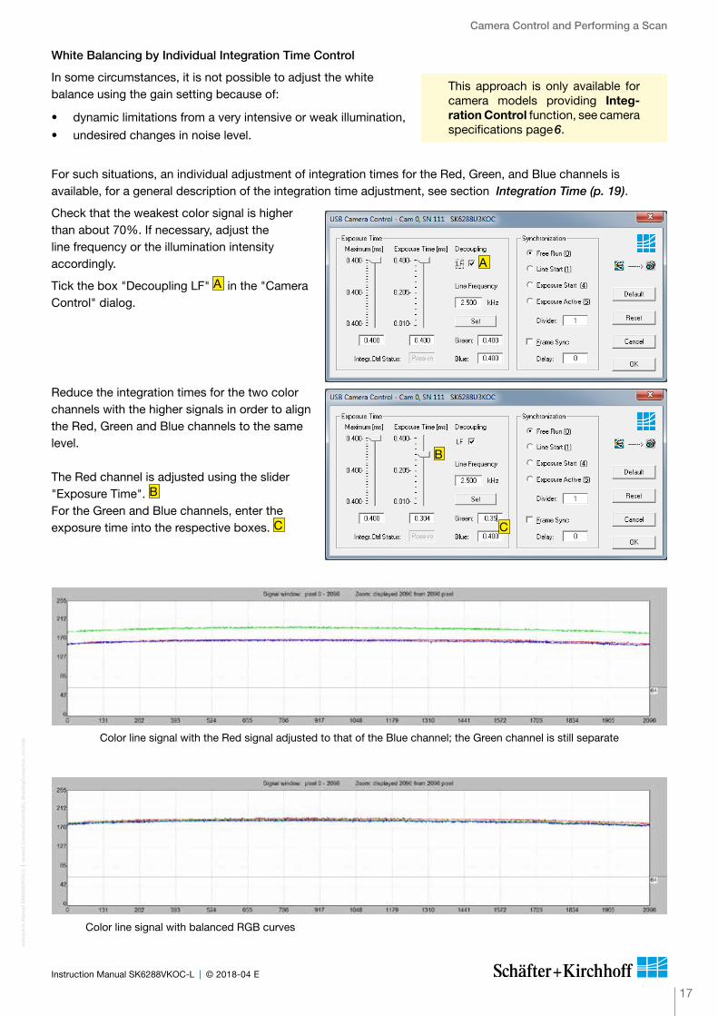
White Balancing by Individual Integration Time Control
In some circumstances, it is not possible to adjust the white balance using the gain setting because of:
• dynamic limitations from a very intensive or weak illumination,
• undesired changes in noise level.
For such situations, an individual adjustment of integration times for the Red, Green, and Blue channels is available, for a general description of the integration time adjustment, see section Integration Time (p. 19).
Check that the weakest color signal is higher than about 70%. If necessary, adjust the line frequency or the illumination intensity accordingly.
Tick the box "Decoupling LF" A in the "Camera Control" dialog.
Reduce the integration times for the two color channels with the higher signals in order to align the Red, Green and Blue channels to the same level. The Red channel is adjusted using the slider "Exposure Time". B For the Green and Blue channels, enter the exposure time into the respective boxes. C
Color line signal with the Red signal adjusted to that of the Blue channel; the Green channel is still separate
Color line signal with balanced RGB curves
A
B
C
This approach is only available for camera models providing Integ-ration Control function, see camera specifications page 6.

Camera Control and Performing a Scan
Inst
ruct
ion
Man
ual S
K62
88V
KO
C-L
shar
ed_C
amer
aCo
ntro
l(2b
)_S
had
ing
Co
rrec
tion_
col.i
ndd
18
Instruction Manual SK6288VKOC-L © 2018-04 E
a) Using a white homogeneous background
• Open the Shading Correction dialog (Alt+s).
Use the entries in the left column to obtain shading correction reference data from a white homogeneous background.
• Use a homogeneous white object to acquire the reference data, e.g. a white sheet of paper.
• Either take a 2-dimensional scan ("Area Scan Function" [F3] ) or
use a single line signal that was averaged over a number of single line scans.
• To suppress any influence from the surface structure, move the imaged object during the image acquisition.
• Input the scale range: Minimum in %: intensity values lower than
“Minimum” will not be changed. A typical appropriate value is 10% of the full
intensity range, i.e. 26 (= 10% · 255) for an 8-bit intensity scale.
Maximum in %: target value for scaling A typical appropriate value is 90% of the full
intensity range. The result will be a homogeneous line at 230 (= 90% 255) for an 8-bit intensity scale.
• Click on button New Reference• Click on Save SCM to Flash to save the SCM
reference signal in the flash memory of the camera
b) Analytic compensation of natural lens vignetting
• Open the Shading Correction dialog (Alt+s). Use the entries in the middle column to calculate
the reference data based on the imaging setup. • Enter the parameters focal length (FL), sensor
length (SL) and field of view (FOV) according to your setup.
The implemented algorithm will compensate the natural lens vignetting.
• Click on Save SCM to Flash to save the SCM reference signal in the flash memory of the camera
Step 2: Obtaining the Shading Correction Data
The shading correction refrence data that is stored in the shading correction memory (SCM) can be obtained in two ways:
Shading Correction dialog
Parameters for correction of natural lens vignetting: FL = Focal Length of the lens in mm SL = Sensor Length in mm FOV = Field Of View in mm
Power-down and Power-up BehaviourThe shading correction memory (SCM) buffer is a volatile memory. Its content is lost on power-off.
Once the reference signal is copied from the SCM to the camera flash memory, it will persist even after a power-down. On a re-start, this data will be restored automatically from the flash memory back into the SCM.
The shading correction status on shutting down - active or not active - will be retained and automatically restored on power-up.
Color line signal with separated RGB curves after Gain Adjustment and Shading Correction
Save SCM to Flash Save the SCM reference signal in the flash memory of the camera
ON Activate Shading Correction with the reference signal that is stored in the SCM.
OFF Switch off Shading Correction. This does not affect the content of the camera SCM buffer or the camera flash memory.
Save SCM to File The SCM reference signal will be stored in a file.
Load File to SCM A stored reference signal will be loaded into the SCM of the camera. If the load process completes then the Shading Correction is active.
Camera Control and Performing a Scan
19
Inst
ruct
ion
Man
ual S
K62
88V
KO
C-L
shar
ed_C
amer
aCo
ntro
l(2c)
_Int
egra
tionT
ime_
ML.
ind
d
Instruction Manual SK6288VKOC-L © 2018-04 E
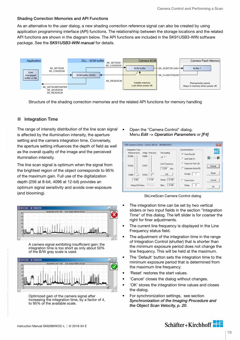
� Integration Time
The range of intensity distribution of the line scan signal is affected by the illumination intensity, the aperture setting and the camera integration time. Conversely, the aperture setting influences the depth of field as well as the overall quality of the image and the perceived illumination intensity.
The line scan signal is optimum when the signal from the brightest region of the object corresponds to 95% of the maximum gain. Full use of the digitalization depth (256 at 8-bit, 4096 at 12-bit) provides an optimum signal sensitivity and avoids over-exposure (and blooming).
A camera signal exhibiting insufficient gain: the integration time is too short as only about 50% of the B/W gray scale is used.
Optimized gain of the camera signal after increasing the integration time, by a factor of 4, to 95% of the available scale.
Shading Correction Memories and API Functions
As an alternative to the user dialog, a new shading correction reference signal can also be created by using application programming interface (API) functions. The relationshhip between the storage locations and the related API functions are shown in the diagram below. The API functions are included in the SK91USB3-WIN software package. See the SK91USB3-WIN manual for details.
Structure of the shading correction memories and the related API functions for memory handling
Cam
era
Con
trol
and
Per
form
ing
a S
can
• Open the "Camera Control" dialog. Menu Edit -> Operation Parameters or [F4]
• The integration time can be set by two vertical sliders or two input fields in the section "Integration Time" of this dialog. The left slider is for coarser the right for finer adjustments.
• The current line frequency is displayed in the Line Frequency status field.
• The adjustment of the integration time in the range of Integration Control (shutter) that is shorter than the minimum exposure period does not change the line frequency. This will be held at the maximum.
• The 'Default' button sets the integration time to the minimum exposure period that is determined from the maximum line frequency.
• 'Reset' restores the start values.
• 'Cancel' closes the dialog without changes.
• 'OK' stores the integration time values and closes the dialog.
• For synchronization settings, see section Synchronization of the Imaging Procedure and the Object Scan Velocity, p. 20.
SkLineScan Camera Control dialog

FOV
S
V0
Pixel #1
Pixel #1
WP / ß
CCD Sensor
Scan Object
Camera Control and Performing a Scan
Inst
ruct
ion
Man
ual S
K62
88V
KO
C-L
shar
ed_C
amer
aCo
ntro
l(3)_
Syn
c_M
L.in
dd
20
Instruction Manual SK6288VKOC-L © 2018-04 E
The optimum object scan velocity is calculated from:
WP · fLVO = ß
If the velocity of the object carrier is not adjustable then the line frequency of the camera must be adjusted to provide an image with the correct aspect ratio, where:
VO · ßfL = WP
VO = object scan velocity
WP = pixel width
fL = line frequency
S = sensor length
FOV = field of view
ß = magnification = S / FOV
A two-dimensional image is generated by moving either the object or the camera. The direction of the translation movement must be orthogonal to the sensor axis of the CCD line scan camera.
To obtain a proportional image with the correct aspect ratio, a line-synchronous transport with the laterally correct pixel assignment is required. The line frequency and the constant object velocity have to be coordinated.
In cases of a variable object velocity or particularly high accuracy requirements then an external synchronization is necessary. The various synchronization modes are described below.
Example 1:
Calculating the object scan velocity for a given field of view and line frequency:
Pixel width = 14 µm
Line frequency = 9.26 kHz
S = 29.3 mm
FOV = 50 mm
14 µm · 9.26 kHzVO = (29.3 mm / 50 mm)
= 221 mm/s
Example 2:
Calculating the line frequency for a given field of view and object scan velocity:
Pixel width = 14 µm
Object scan velocity = 200 mm/s
S = 29.3 mm
FOV = 50 mm
200 mm/s · (29.3 mm / 50 mm)fL = 14 µm
= 8.4 kHz
� Synchronization of the Imaging Procedure and the Object Scan Velocity
Cam
era
Con
trol
and
Per
form
ing
a S
can

Camera Control and Performing a Scan
21
Inst
ruct
ion
Man
ual S
K62
88V
KO
C-L
shar
ed_C
amer
aCo
ntro
l(3b
)_S
ync-
Mo
des
_Gig
E+
V_U
SB
3_M
L.in
dd
Instruction Manual SK6288VKOC-L © 2018-04 E
Cam
era
Con
trol
and
Per
form
ing
a S
can
Free Run / SK Mode 0
The acquisition of each line is internally synchronized (free-running) and the next scan is started automatically on completion of the previous line scan. The line frequency is determined by the programmed value.
LineStart / SK Mode 1
On an external trigger, the currently exposed line will be read out at the next internal line clock. The start and duration of exposure are controlled internally by the camera and are not affected by the trigger. The exposure time is programmable and the trigger does not affect the integration time. The line frequency is determined by the trigger clock frequency.
Restriction: The period of the trigger signal must be longer than the exposure time used.
ExposureStart / SK Mode 4 (only available when camera supports integration control)
A new exposure is started exactly at the time of external triggering and the current exposure process will be interrupted. The exposure time is determined by the programmed value. The exposed line will be read out with the next external trigger. The trigger clock frequency determines the line frequency.
Restriction: The period of the trigger signal must be longer than the exposure time used.ExposureActive / SK extSOS (Mode 5)
The exposure time and the line frequency are controlled by the external trigger signal. This affects both the start of a new exposure (start-of-scan pulse, SOS) and the reading out of the previously exposed line.
FrameTrigger / SK FrameSync
The frame trigger synchronizes the acquisition of a 2D area scan. The individual line scans in this area scan can be synchronized in any of the available line trigger modes. The camera suppresses the data transfer until a falling edge of a TTL signal occurs at the FRAME SYNC input. The number of lines that defines the size of the frame must be programmed in advance.
FRAME SYNC
LINE SYNC
Video
Video Valid
Data transmission
Combined frame and line synchronization
The synchronization mode determines the timing of the line scan. Synchronization can be either performed inter-nally or triggered by an external source, e.g. an encoder signal.
The line scan camera can be externally triggered in two different ways:
1. Line-triggered synchronization: Each single line scan is triggered by the falling edge of a TTL signal supplied to LINE SYNC A input. The SK6288VKOC-L line scan camera facilitates advanced synchronization control by a second trigger
input LINE SYNC B. For a detailed description, see Advanced Synchronization Control, p. 282. Frame-triggered synchronization: A set of lines resulting in a 2-dimensional frame or image is triggered by the falling edge of a TTL signal
on FRAME SYNC input.
� Synchronization Modes
Schäfter + Kirchhoff differentiates several trigger modes identified by a number, which can be selected in the control dialog as appropriate.
• Open the 'Camera Control' dialog [F4] to configure the synchronization. The trigger mode settings are available in the middle frame.
• Frame- and line-triggered synchronization can be combined. Tick the 'Frame Sync' box to activate the frame synchronization mode.
• The Trigger Control stage is followed by a Trigger Divider stage inside the camera. Enter the division ratio into the 'Divider' field.
Camera Control dialog
CCD Sensor
Scan Object
FOV
V0
WP / ß
WL / ß
Pixel #1
S
Pixel #1
GR
B
BG
R
� RGB Sensors: 2D Imaging and Pixel Allocation
Cam
era
Con
trol
and
Per
form
ing
a S
can
Camera Control and Performing a Scan
Inst
ruct
ion
Man
ual S
K62
88V
KO
C-L
shar
ed_C
amer
aCo
ntro
l(3c)
_Syn
c_co
l-E
xt_M
L.in
dd
22
Instruction Manual SK6288VKOC-L © 2018-04 E
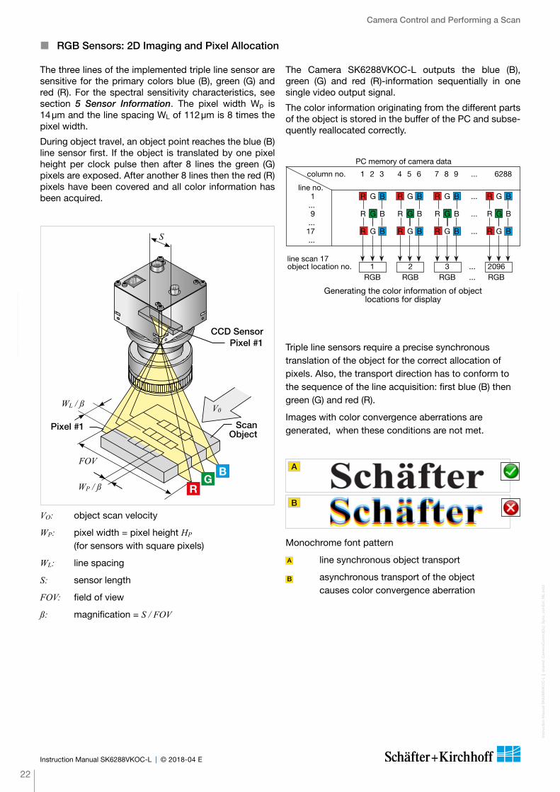
The three lines of the implemented triple line sensor are sensitive for the primary colors blue (B), green (G) and red (R). For the spectral sensitivity characteristics, see section 5 Sensor Information. The pixel width Wp is 14 µm and the line spacing WL of 112 µm is 8 times the pixel width.
During object travel, an object point reaches the blue (B) line sensor first. If the object is transla ted by one pixel height per clock pulse then after 8 lines the green (G) pixels are exposed. After another 8 lines then the red (R) pixels have been covered and all color information has been acquired.
A
B
Monochrome font pattern
A line synchronous object transport
B asynchronous transport of the object causes color convergence aberration
The Camera SK6288VKOC-L outputs the blue (B), green (G) and red (R)-information se quentially in one single video output signal.
The co lor information originating from the different parts of the object is stored in the buffer of the PC and subse-quently reallocated correctly.
Generating the color information of object locations for display
line scan 17 object location no. 1 2 3 ... 2096 RGB RGB RGB ... RGB
PC memory of camera data
column no. 1 2 3 4 5 6 7 8 9 ... 6288
line no. 1 R G B R G B R G B ... R G B ... 9 R G B R G B R G B ... R G B ... 17 R G B R G B R G B ... R G B ...
Triple line sensors require a precise synchronous translation of the object for the correct allocation of pixels. Also, the transport direction has to conform to the sequence of the line acquisition: first blue (B) then green (G) and red (R).
Images with co lor convergence ab er rations are generated, when these conditions are not met.
VO: object scan velocity
WP: pixel width = pixel height HP (for sensors with square pixels)
WL: line spacing
S: sensor length
FOV: field of view
ß: magnification = S / FOV

In
stru
ctio
n M
anua
lGeb
rauc
hsan
leitu
ng S
K62
88V
KO
C-L
shar
ed_b
lank
.ind
d
23
Instruction ManualGebrauchsanleitung SK6288VKOC-L © 2018-04 ED
Camera Control and Performing a Scan
Inst
ruct
ion
Man
ualG
ebra
uchs
anle
itung
SK
6288
VK
OC
-L
sh
ared
_Cam
eraC
ont
rol(3
d)_
Dev
ice-
Fea
ture
-Lis
t_G
igE
V.in
dd
24
Instruction ManualGebrauchsanleitung SK6288VKOC-L © 2018-04 ED
Cam
era
Con
trol
and
Per
form
ing
a S
can
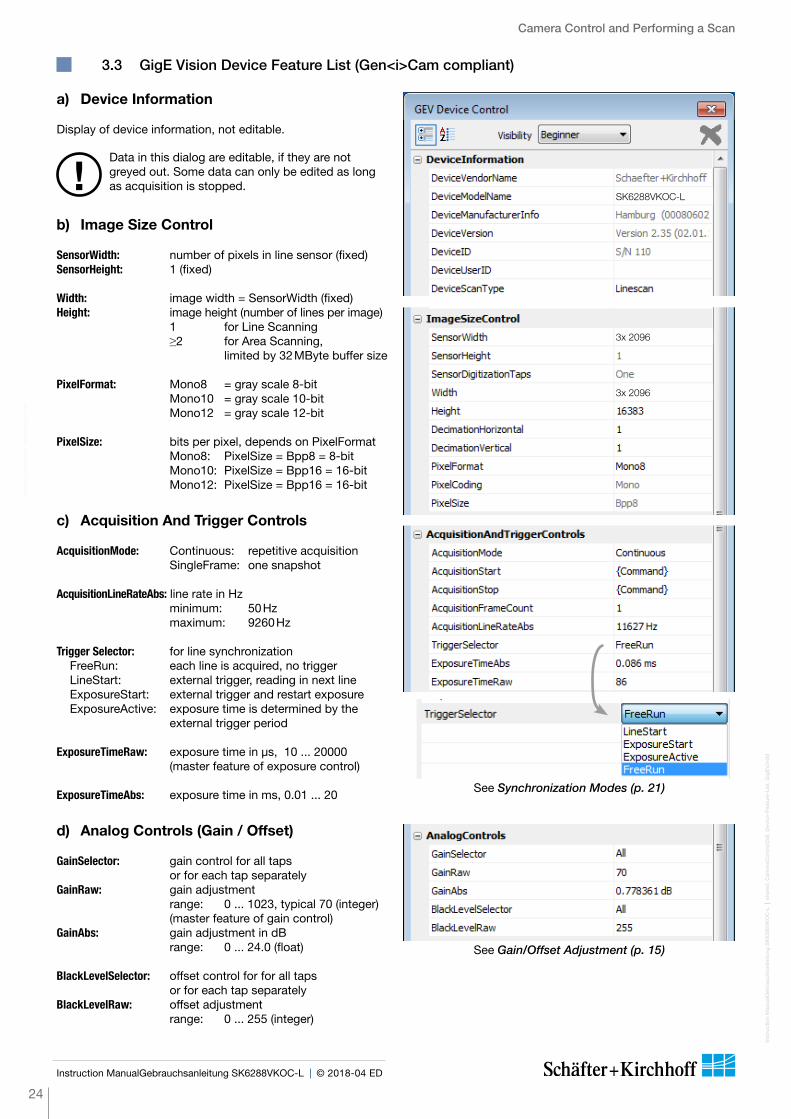
3.3 GigE Vision Device Feature List (Gen<i>Cam compliant)
a) Device Information
Display of device information, not editable.
Data in this dialog are editable, if they are not greyed out. Some data can only be edited as long as acquisition is stopped.!
b) Image Size Control
SensorWidth: number of pixels in line sensor (fixed)SensorHeight: 1 (fixed)
Width: image width = SensorWidth (fixed)Height: image height (number of lines per image) 1 for Line Scanning ≥2 for Area Scanning,
limited by 32 MByte buffer size
PixelFormat: Mono8 = gray scale 8-bit Mono10 = gray scale 10-bit Mono12 = gray scale 12-bit
PixelSize: bits per pixel, depends on PixelFormat Mono8: PixelSize = Bpp8 = 8-bit Mono10: PixelSize = Bpp16 = 16-bit Mono12: PixelSize = Bpp16 = 16-bit
c) Acquisition And Trigger Controls
AcquisitionMode: Continuous: repetitive acquisition SingleFrame: one snapshot
AcquisitionLineRateAbs: line rate in Hz minimum: 50 Hz maximum: 9260 Hz
Trigger Selector: for line synchronization FreeRun: each line is acquired, no trigger LineStart: external trigger, reading in next line ExposureStart: external trigger and restart exposure ExposureActive: exposure time is determined by the
external trigger period
ExposureTimeRaw: exposure time in µs, 10 ... 20000 (master feature of exposure control)
ExposureTimeAbs: exposure time in ms, 0.01 ... 20
d) Analog Controls (Gain / Offset)
GainSelector: gain control for all taps or for each tap separately
GainRaw: gain adjustment range: 0 ... 1023, typical 70 (integer) (master feature of gain control)
GainAbs: gain adjustment in dB range: 0 ... 24.0 (float)
BlackLevelSelector: offset control for for all taps or for each tap separately
BlackLevelRaw: offset adjustment range: 0 ... 255 (integer)
3x 2096
3x 2096
SK6288VKOC-L
See Synchronization Modes (p. 21)
See Gain/Offset Adjustment (p. 15)

Camera Control and Performing a Scan
25
Inst
ruct
ion
Man
ualG
ebra
uchs
anle
itung
SK
6288
VK
OC
-L
sh
ared
_Cam
eraC
ont
rol(3
d)_
Dev
ice-
Fea
ture
-Lis
t_G
igE
V.in
dd
Instruction ManualGebrauchsanleitung SK6288VKOC-L © 2018-04 ED
e) Custom Features, Beginner view
SkGetPixFrequencyHigh: returns the high pixel frequency in kHz
SkGetPixFrequencyLow: returns the low pixel frequency in kHz
SkSetPixelFrequency: sets the pixel frequency in kHz (low or high) with reciprocal effect on line frequency.
For lower line frequencies, a low value for pixel frequency is recommended.
SkSetShadingCorrection: ON: activates Shading Correction OFF: deactivates Shading Correction See White Balance and Shading
Correction (p. 16).
SkGetMaxLineFrequency: returns the maximum line rate in Hz
SkGetMinExposureTime: returns the minimum exposure time in microseconds
SkFrameTrigger: selects "Frame Sync" for external trigger of images
True: Frame Trigger is active FALSE: Frame Trigger is off The Frame Trigger works with all Line
Trigger modes. See Synchronization Modes (p. 21).
SkGetVideoChannels: returns the number of taps for gain /offset control
SkGetSerialNumber: returns the serial number of the camera
SkGetRevisionNumber: returns the revision number for the camera
SkSyncControl: Sync Control Register setting, see Advanced Trigger Functions and Sync Control Register Settings (p. 28).
SkSyncDivider: incoming trigger clock divider (integer)
f) Additional Custom Features, Guru view
SkShadCorrReference: a single line scan is acquired using a white background and saved in the Shading Correction Memory (SCM).
For each pixel, a correction factor is calculated for adjusting the intensity to the maximum (255 at Mono8). When Shading Correction is active then all of following scans are normalized using this factor.
SkSaveScmToFlash: writes the Shading Correction Memory factors into the non-volatile flash memory of the camera, allowing use of the SCM even after a complete shut down or loss of power.
SkTestPattern: switch on test pattern, turns off with power off
10
9260
Rev. 2.35
60
30
30
3
10
9260
Rev. 2.35
60
30
30
3
Advanced SkLineScan Software Functions
Inst
ruct
ion
Man
ual S
K62
88V
KO
C-L
SK
6288
VK
OC
-L_C
amer
aCo
ntro
l(4)_
ByC
om
man
ds.
ind
d
26
Instruction Manual SK6288VKOC-L © 2018-04 E
4 Advanced SkLineScan Software Functions
4.1 Camera Control by Commands
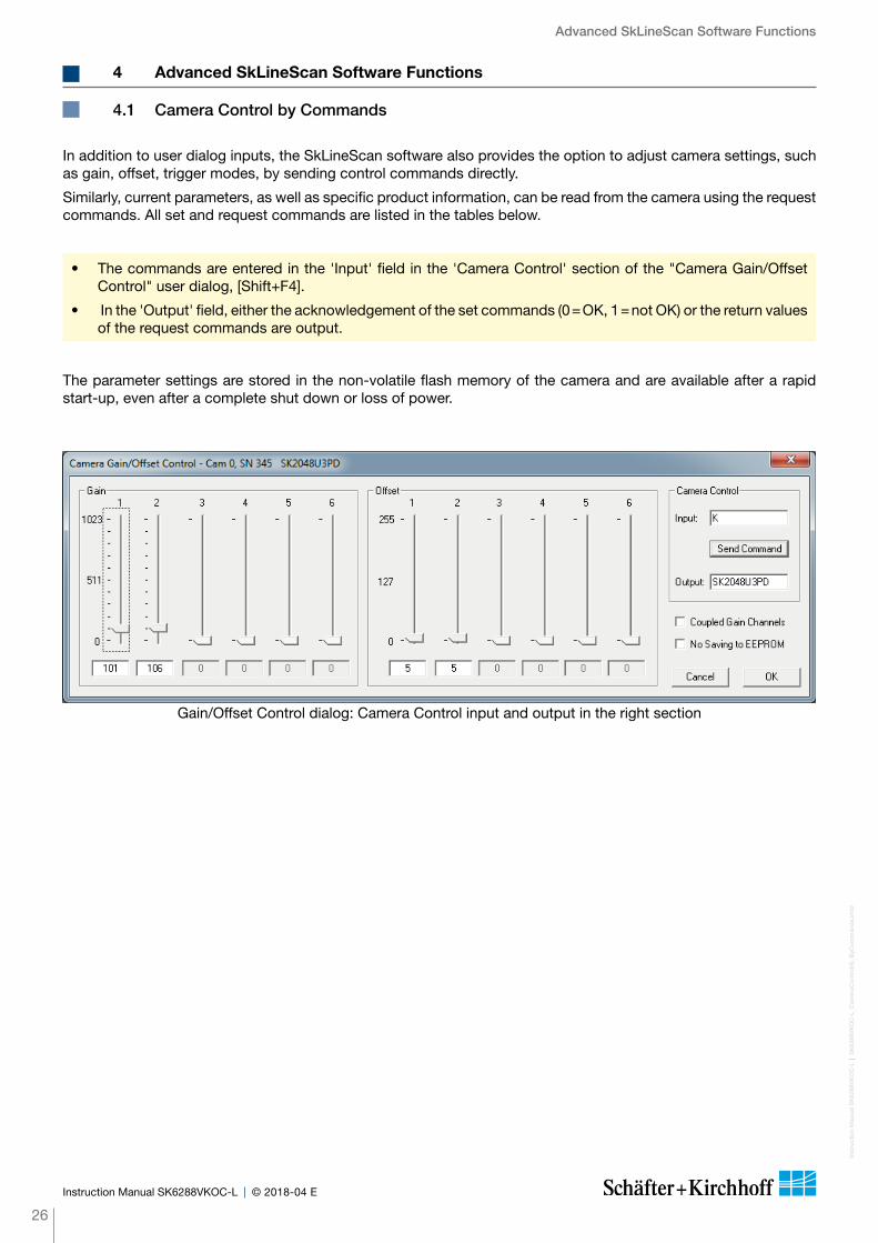
In addition to user dialog inputs, the SkLineScan software also provides the option to adjust camera settings, such as gain, offset, trigger modes, by sending control commands directly.
Similarly, current parameters, as well as specific product information, can be read from the camera using the request commands. All set and request commands are listed in the tables below.
• The commands are entered in the 'Input' field in the 'Camera Control' section of the "Camera Gain/Offset Control" user dialog, [Shift+F4].
• In the 'Output' field, either the acknowledgement of the set commands (0 = OK, 1 = not OK) or the return values of the request commands are output.
The parameter settings are stored in the non-volatile flash memory of the camera and are available after a rapid start-up, even after a complete shut down or loss of power.
Gain/Offset Control dialog: Camera Control input and output in the right section
Advanced SkLineScan Software FunctionsIn
stru
ctio
n M
anua
l SK
6288
VK
OC
-L
S
K62
88V
KO
C-L
_Cam
eraC
ont
rol(4
)_B
yCo
mm
and
s.in
dd
27
Instruction Manual SK6288VKOC-L © 2018-04 E
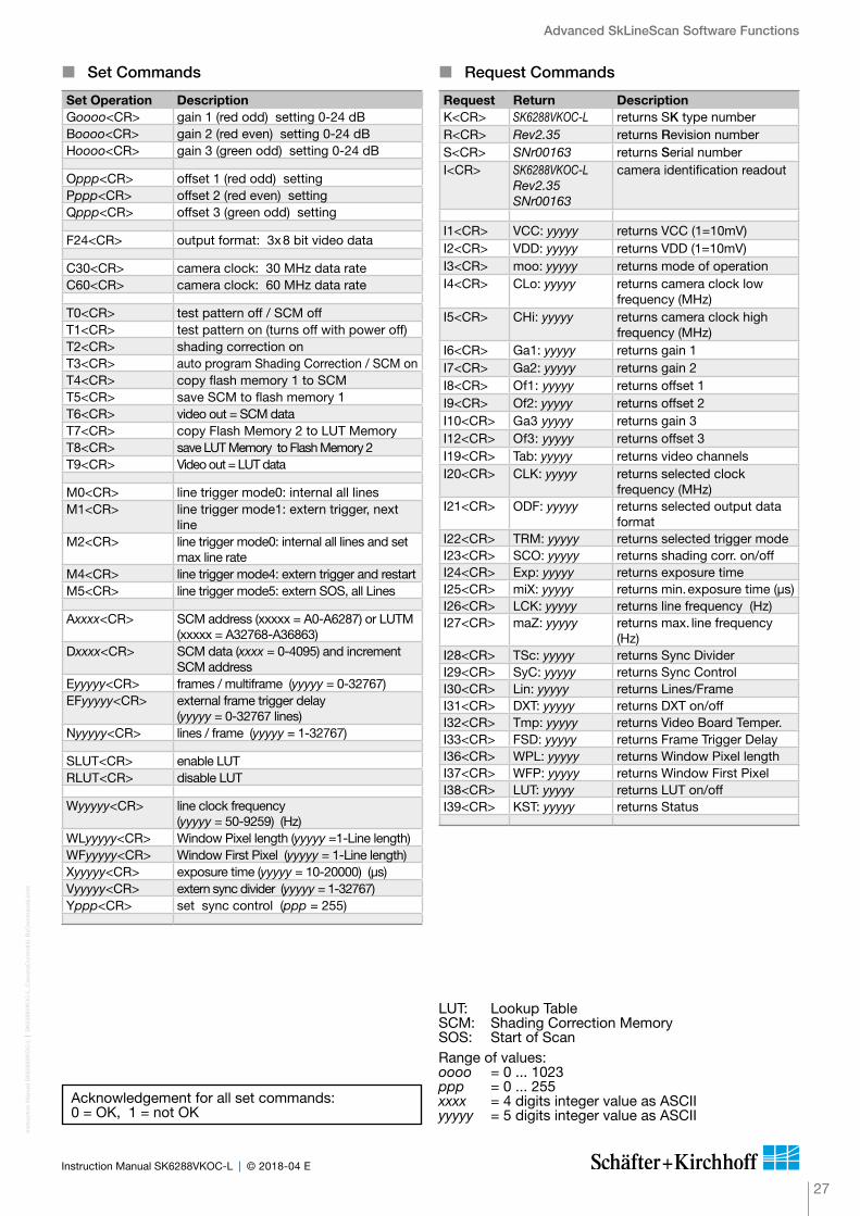
� Set Commands
Set Operation DescriptionGoooo<CR> gain 1 (red odd) setting 0-24 dB Boooo<CR> gain 2 (red even) setting 0-24 dB Hoooo<CR> gain 3 (green odd) setting 0-24 dB
Oppp<CR> offset 1 (red odd) settingPppp<CR> offset 2 (red even) settingQppp<CR> offset 3 (green odd) setting
F24<CR> output format: 3x 8 bit video data
C30<CR> camera clock: 30 MHz data rate C60<CR> camera clock: 60 MHz data rate
T0<CR> test pattern off / SCM offT1<CR> test pattern on (turns off with power off)T2<CR> shading correction onT3<CR> auto program Shading Correction / SCM onT4<CR> copy flash memory 1 to SCMT5<CR> save SCM to flash memory 1T6<CR> video out = SCM dataT7<CR> copy Flash Memory 2 to LUT MemoryT8<CR> save LUT Memory to Flash Memory 2T9<CR> Video out = LUT data
M0<CR> line trigger mode0: internal all linesM1<CR> line trigger mode1: extern trigger, next
lineM2<CR> line trigger mode0: internal all lines and set
max line rate M4<CR> line trigger mode4: extern trigger and restartM5<CR> line trigger mode5: extern SOS, all Lines
Axxxx<CR> SCM address (xxxxx = A0-A6287) or LUTM (xxxxx = A32768-A36863)
Dxxxx<CR> SCM data (xxxx = 0-4095) and increment SCM address
Eyyyyy<CR> frames / multiframe (yyyyy = 0-32767) EFyyyyy<CR> external frame trigger delay
(yyyyy = 0-32767 lines) Nyyyyy<CR> lines / frame (yyyyy = 1-32767)
SLUT<CR> enable LUTRLUT<CR> disable LUT
Wyyyyy<CR> line clock frequency (yyyyy = 50-9259) (Hz)
WLyyyyy<CR> Window Pixel length (yyyyy =1-Line length)WFyyyyy<CR> Window First Pixel (yyyyy = 1-Line length)Xyyyyy<CR> exposure time (yyyyy = 10-20000) (µs)Vyyyyy<CR> extern sync divider (yyyyy = 1-32767) Yppp<CR> set sync control (ppp = 255)
� Request Commands
Request Return DescriptionK<CR> SK6288VKOC-L returns SK type numberR<CR> Rev2.35 returns Revision numberS<CR> SNr00163 returns Serial numberI<CR> SK6288VKOC-L
Rev2.35SNr00163
camera identification readout
I1<CR> VCC: yyyyy returns VCC (1=10mV)I2<CR> VDD: yyyyy returns VDD (1=10mV)I3<CR> moo: yyyyy returns mode of operationI4<CR> CLo: yyyyy returns camera clock low
frequency (MHz)I5<CR> CHi: yyyyy returns camera clock high
frequency (MHz)I6<CR> Ga1: yyyyy returns gain 1I7<CR> Ga2: yyyyy returns gain 2I8<CR> Of1: yyyyy returns offset 1I9<CR> Of2: yyyyy returns offset 2I10<CR> Ga3 yyyyy returns gain 3I12<CR> Of3: yyyyy returns offset 3I19<CR> Tab: yyyyy returns video channelsI20<CR> CLK: yyyyy returns selected clock
frequency (MHz)I21<CR> ODF: yyyyy returns selected output data
formatI22<CR> TRM: yyyyy returns selected trigger modeI23<CR> SCO: yyyyy returns shading corr. on/offI24<CR> Exp: yyyyy returns exposure timeI25<CR> miX: yyyyy returns min. exposure time (µs)I26<CR> LCK: yyyyy returns line frequency (Hz)I27<CR> maZ: yyyyy returns max. line frequency
(Hz)I28<CR> TSc: yyyyy returns Sync Divider I29<CR> SyC: yyyyy returns Sync Control I30<CR> Lin: yyyyy returns Lines/Frame I31<CR> DXT: yyyyy returns DXT on/offI32<CR> Tmp: yyyyy returns Video Board Temper.I33<CR> FSD: yyyyy returns Frame Trigger DelayI36<CR> WPL: yyyyy returns Window Pixel lengthI37<CR> WFP: yyyyy returns Window First PixelI38<CR> LUT: yyyyy returns LUT on/offI39<CR> KST: yyyyy returns Status
Range of values:oooo = 0 ... 1023ppp = 0 ... 255xxxx = 4 digits integer value as ASCIIyyyyy = 5 digits integer value as ASCII
LUT: Lookup TableSCM: Shading Correction MemorySOS: Start of Scan
Acknowledgement for all set commands:0 = OK, 1 = not OK

Advanced SkLineScan Software Functions
Inst
ruct
ion
Man
ual S
K62
88V
KO
C-L
shar
ed_C
amer
aCo
ntro
l(5)_
Ad
vanc
ed-S
ync-
Ctr
l_M
L.in
dd
28
Instruction Manual SK6288VKOC-L © 2018-04 E
Ad
vanc
ed S
kLin
eSca
n S
oftw
are
Func
tions
4.2 Advanced Synchronization Control
� Advanced Trigger Functions and Sync Control Register Settings
• Basic synchronization function, 'Camera Control' dialog settings are valid A
• Detection of direction B , C , D , E
• Trigger pulses are valid only in one direction, trigger pulses in the other direction are ignored B
• Trigger on 4 edges D , E
• Suppression of machine-encoded jitter, programmable hysteresis for trigger control E
Sync Control Register (SCR) SyC7 SyC6 SyC5 SyC4 SyC3 SyC2 SyC1 SyC0default x x x x x x 0 0pixel #1 data = external trigger input states x x x x x x 0 1pixel #1 data = Linecounter (8 bit) x x x x x x 1 0pixel #1, #2 data = ext. trigger states (3 bit) + line counter (13 bit)
x x x x x x 1 1
ExSOS and Sync at LINE SYNC A (Mode5) x x x x x 0 x xExSOS at LINE SYNC B,Sync at LINE SYNC A (Mode5)
x x x x x 1 x x
Jitter Hysterese off x x x 0 0 x x xJitter Hysterese 4 x x x 0 1 x x xJitter Hysterese 16 x x x 1 0 x x xJitter Hysterese 64 x x x 1 1 x x xSync 1x Enable x x 0 x x x x xSync 4x Enable x x 1 x x x x xSync up Enable / down disable x 0 x x x x x xSync up/down Enable x 1 x x x x x xSync Ctrl. Disable, SyC3...SyC6 without function 0 x x x x x x xSync Control Enable 1 x x x x x x x
128 64 32 16 8 4 2 1
For diagnostic purposes, the present state of external trigger inputs (LINE SYNC A, LINE SYNC B, FRAME SYNC) or the internal line counter can be output instead of pixel #1 and/or pixel #2 data.
SCR Pixel #1 Data (lowByte) Pixel #2 Data (lowByte)
xxxxxx00 intensity intensity
xxxxxx01
D7 = FRAME SYNCD6 = LINE SYNC AD5 = LINE SYNC BD4 ... D0 = 0
intensity
xxxxxx10 internal line counter (8 bit) intensity
xxxxxx11
D7 = FRAME SYNCD6 = LINE SYNC AD5 = LINE SYNC BD4 ... D0 = line counter (bit 12 ... 8)
internal line counter (bit 7 ... 0)
The basic synchronization function makes use of the trigger input LINE SYNC A. The trigger mode is determined by the settings in the "Camera Control" dialog, e.g. LineStart (1) or ExposureStart (4).
Advanced trigger functions are provided by combining LINE SYNC A with a second trigger input LINE SYNC B. The operation mode is controlled by the entries in the Sync Control Register (SCR).
Example:
Y232 ppp = 232(dec) = 11101000(bin)
new SCR value: 11101000 E
Use control commands to write to or to read from the Sync Control Register:
Yppp<CR> set sync control with ppp = 0...255 (decimal) Return value: 0 = OK; 1 = not OK
I29<CR> return sync control Return value: SyC:yyyyy (5-digits integer value as ASCII)

Advanced SkLineScan Software Functions
29
Inst
ruct
ion
Man
ual S
K62
88V
KO
C-L
shar
ed_C
amer
aCo
ntro
l(5)_
Ad
vanc
ed-S
ync-
Ctr
l_M
L.in
dd
Instruction Manual SK6288VKOC-L © 2018-04 E
• Trigger on falling edge of SyncA• SyncB = low active• direction detection = on• hysteresis = 0
Sync Control Register:'1000 0xxx'b
B
1)
• Trigger on falling edge of SyncA• SyncB without function• direction detection = off• hysteresis = 0
Sync Control Register:'0xxx xxxx'b
A
1)
• Trigger on falling edge of SyncA• SyncB = low/high active• direction detection = on• hysteresis = 0
Sync Control Register:'1100 0xxx'b
C
1)
• Trigger on 4 edges of SyncA and SyncB• direction detection = on• hysteresis = 0
Sync Control Register:'1110 0xxx'b
D
1)
• Trigger on 4 edges of SyncA and SyncB• direction detection = on• hysteresis = 4
Sync Control Register:'1110 1xxx'b
E
2)
1)
1)1)
machine holdup oscillation
� Example Timing Diagrams of Advanced Synchronization Control
Annotations:
SyncA = LINE SYNC A (external line synchronization input, I/O connector)SyncB = LINE SYNC B (external line synchronization input, I/O connector)Count = internal counterTrigger = Generated trigger pulses from the Trigger Control stage. The signal goes to the Trigger
Divider stage inside the camera. For setting the divider, use the Vyyyyy<CR> command or the 'Divider' input field in the 4.1 Camera Control by Commands (p. 20).
1) direction changed 2) glitch

Sensor Information
Inst
ruct
ion
Man
ual S
K62
88V
KO
C-L
shar
ed_S
enso
r_K
LI-2
113.
ind
d
30
Instruction Manual SK6288VKOC-L © 2018-04 E
5 Sensor Information
Manufacturer: Eastman Kodak CompanyType: KLI2113Data source: Kodak Digital Science KLI-2113 Image Sensor, Technical Data Revision 4
a) Single Channel Schematic
b) Package Configuration
Sensor InformationIn
stru
ctio
n M
anua
l SK
6288
VK
OC
-L
sh
ared
_Sen
sor_
KLI
-211
3.in
dd
31
Instruction Manual SK6288VKOC-L © 2018-04 E
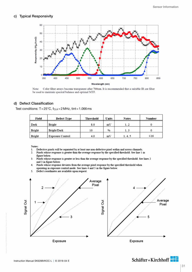
c) Typical Responsivity
d) Defect ClassificationTest conditions: T = 25°C, fCLK = 2 MHz, tint = 1.066 ms

Sensor Information
Inst
ruct
ion
Man
ual S
K62
88V
KO
C-L
shar
ed_S
enso
r_K
LI-2
113.
ind
d
32
Instruction Manual SK6288VKOC-L © 2018-04 E
e) Electro-optical Characteristics
In
stru
ctio
n M
anua
lGeb
rauc
hsan
leitu
ng S
K62
88V
KO
C-L
shar
ed_b
lank
_2nd
-Ins
tanc
e.in
dd
33
Instruction ManualGebrauchsanleitung SK6288VKOC-L © 2018-04 ED
Inst
ruct
ion
Man
ual S
K62
88V
KO
C-L
shar
ed_G
loss
ary.
ind
d
34
Instruction Manual SK6288VKOC-L © 2018-04 E
Glossary
Blooming
If by overexposure too many charge carriers are produced in one or several photosensitive elements (pixels) of the line sensor, the transport register is „flooded“ with charge carriers, and also the following register bins are charged over the saturation limit. This spreading of a local overex-posure along a line is called „blooming“. In the resulting video signal an overexposed area includes too many pixels. In that area the geometric mapping between image and object is not correct.
CCD line scan cameras with anti-blooming sensors direct the abundant charge to a ”drain gate”. Charge overflow into adjacent, less illuminated pixels is prevented. Depending on pixel frequency and spectral range, overexposure up to factor of 50 can thus be handled.
Exposure period
is the illumination cycle of a line scan sensor. It is the integration time plus the additional time to complete the read-out of the accumulated charges and the output procedure. While the charges from a finished line scan are being read out, the next line scan is being exposed. The exposure period is a function of the pixel number and the pixel frequency. The minimum exposure period of a particular line scan camera determines the maximum line frequency that is declared in the specifications.
Integration control
Cameras with integration control are capable of curtailing the integration time within an exposure period. This performs an action equivalent to a shutter mechanism.
Integration time
The light-sensitive elements of the photoelectric sensor accumulate the charge that is generated by the incident light. The duration of this charge accumulation is called the integration time. Longer integration times increase the intensity of the line scan signal, assuming constant illumination conditions. The complete read-out of accumulated charges and output procedure determines the minimum exposure period.
Line frequency, line scan frequency
is the reciprocal value of the exposure period. The maximum line frequency is a key criterion for line scan sensors as this is the limiting factor for the scan velocity.
Optical resolution
Two elements of a line scan camera determine the optical resolution of the system: first, the pixel configuration of the line sensor and, secondly, the optical resolution of the lens. The worst value is the determining value. In a phased set-up, both are within the same range.
The optical resolution of the line sensor is primarily determined by the number of pixels and secondarily by their size and spacing, the inter-pixel distance. Currently available line scan cameras have up to 12 000 pixels, ranging from 4 to 14 µm in size and spacing, for sensors up to 56 mm in length and line scan frequencies up to 83 kHz.
During a scanning run, the effective resolution perpen-dicular to the sensor orientation is determined by the velocity of the scan and by the line frequency
Pixel frequency
The pixel frequency for an individual sensor is the rate of charge transfer from pixel to pixel and its ultimate conversion into a signal.
Region of Interest
A freely programmable window (region of interest, ROI) can be applied to the line sensor so that only the pixel information within the ROI can reach the memory.
By only illuminating these ranges, data volume and data processing is accelerated for both line and area scan acquisitions.
Constraint: the ROI memory allocation must be divisible by 8.
Shading correction
Shading Correction, section 3.2
SCM
Shading Correction Memory,
Shading Correction Memories and API Functions, section 3.2
SoI (Start of Integration)
In addition to SoS, cameras with Integration Control function generate an internal SoI-signal that initiates the integration period.
SoS (Start of Scan)
is an internally generated trigger signal for sequential control of the camera, The signal is induced either by an internal counter or by an external line synchronization signal, depending on the selected line synchronization mode.
Synchronization
Advanced Synchronization Control, section 4.2
35
Inst
ruct
ion
Man
ual S
K62
88V
KO
C-L
shar
ed_G
loss
ary.
ind
d
Instruction Manual SK6288VKOC-L © 2018-04 E
SkLineScan
is the software application from Schäfter + Kirchhoff for controlling and adjusting the line scan cameras,
Software: SkLineScan, section 3.1
Synchronization
To obtain a proportional image with the correct aspect ratio, a line synchronous transport with the laterally correct pixel assignment is required. The Line frequency and constant object velocity have to be compatible with each other.
For more accurate requirements or with a variable object velocity, external synchronization is necessary.
Synchronization of the Imaging Procedure and the Object Scan Velocity, section 3.2
Thresholding (monochrome cameras only)
The thresholding process generates a binary signal from the gray scale data, with values below the threshold yielding 0 and those above yielding 1. Only the pixel addresses of the location and threshold transition (from high→low or low→high) are transmitted, reducing data throughput.
Thresholding is particularly appropriate for measuring widths or edge positions, by simply masking the required pixel addresses.

Inst
ruct
ion
Man
ualG
ebra
uchs
anle
itung
SK
6288
VK
OC
-L
sh
ared
_bla
nk_3
rd-I
nsta
nce.
ind
d
36
Instruction ManualGebrauchsanleitung SK6288VKOC-L © 2018-04 ED

The product complies with the following standards and directives:
2014/30/EU
EMC Directive
DIN EN 61326-1:2013
Electrical equipment for measurement, control and laboratory use – EMC requirements
Part 1: General requirements
CE-Conformity
In
stru
ctio
n M
anua
l SK
6288
VK
OC
-L
sh
ared
_CE
-Co
nfo
rmity
_War
rant
y_M
L.in
dd
37
Instruction Manual SK6288VKOC-L © 2018-04 E
Copyright ©
Unless explicitly allowed, distribution, sale or use of this document or its contents, for purposes other than those intended, is forbidden. Repeated transgressions will lead to prosecution and demands for compensation.
All rights of patent protection and registration or copyright of a product or its design lie with Schäfter+Kirchhoff. Schäfter+Kirchhoff GmbH and the Schäfter+Kirchhoff logo are registered trademarks.
We reserve the right to improve or change specifications so that the system description and depictions in the Instruction Manual may differ in detail from the system actually supplied. The Instruction Manual is not covered by an update service.
Date of document publication: 17.04.2018
Schäfter+Kirchhoff GmbH Tel.: +49 40 853 997-0 Kieler Straße 212 Fax: +49 40 853 997-10 22525 Hamburg Email: [email protected] Germany Internet: www.SuKHamburg.com
This manual has been prepared and reviewed as carefully as possible but no warranty is given or implied for any errors of fact or in interpretation that may arise. If an error is suspected then the reader is kindly requested to inform us for appropriate action.
The circuits, descriptions and tables may be subject to and are not meant to infringe upon the rights of a third party and are provided for informational purposes only.
The technical descriptions are general in nature and apply only to an assembly group. A particular feature set, as well as its suitability for a particular purpose, is not guaranteed.
Each product is subjected to a quality control process. If a failure should occur then please contact the supplier or Schäfter + Kirchhoff GmbH immediately. The warranty period covers the 24 months from the delivery date. After the warranty has expired, the manufacturer guarantees an additional 6 months warranty for all repaired or substi-tuted product components. Warranty does not apply to any damage resulting from misuse, inappropriate modifi-cation or neglect. The warranty also expires if the product is opened. The manufacturer is not liable for consequential damage. If a failure occurs during the warranty period then the product will be replaced, calibrated or repaired without further charge. Freight costs must be paid by the sender. The manufacturer reserves the right to exchange components of the product instead of making a repair. If the failure results from misuse or neglect then the user must pay for the repair. A cost estimate can be provided beforehand.
Warranty
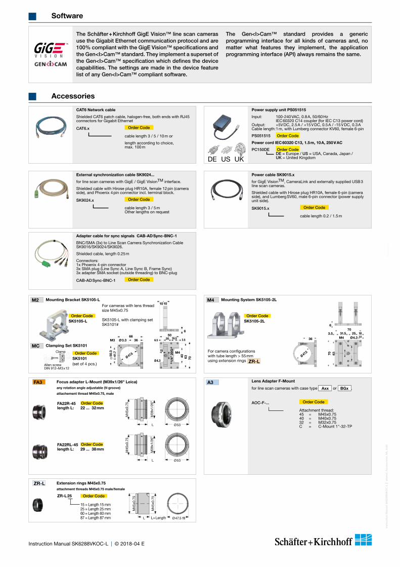
Lens Adapter F-Mount
for line scan cameras with case type Axx or BGx .
AOC-F-... Order Code
Attachment thread: 45 = M45x0.75 40 = M40x0.75 32 = M32x0.75 C = C-Mount 1"-32-TP
A3
M45
x0.7
5M
45x0
.75
M39
x1/2
6’’
M39
x1/2
6’’
Ø53
Ø53
L
L
FA22RL-45 Order Codelength L: 29 ... 38 mm
FA22R-45 Order Codelength L: 22 ... 32 mm
FA3 Focus adapter L-Mount (M39x1/26" Leica) any rotation angle adjustable (V-groove)
attachement thread M45x0.75, male
Ø47.5 f8
M45
x0.7
5
M45
x0.7
5
L L=Length
ZR-L Extension rings M45x0.75 attachment threads M45x0.75 male/female
ZR-L 25 Order Code
15 = Length 15 mm 25 = Length 25 mm 60 = Length 60 mm 87 = Length 87 mm
M2 Mounting Bracket SK5105-L
MC Clamping Set SK5101
66
1010
36M3 Ø3.3
6
50.3
41.7
Ø 47.5
For cameras with lens thread size M45x0.75
SK5105-L with clamping set SK5101#
Allen screwDIN 912–M3x12
Clamp
5020 16.5 3.56.5
Ø4.3
15M4
1/4’
’ 20G
40 63 70
Order CodeSK5101(set of 4 pcs.)
Order CodeSK5105-L
M4 Mounting System SK5105-2L
For camera configurations with tube length > 55 mm using extension rings ZR-L
6
36
Ø 47.5
703.5 31.5 25 10
3.5
70 63 40
1/4’
’ 20G
M4 Ø4.3
Order CodeSK5105-2L
CAT6 Network cable
Shielded CAT6 patch cable, halogen-free, both ends with RJ45 connectors for Gigabit Ethernet
CAT6.x Order Code
cable length 3 / 5 / 10 m or
length according to choice, max. 100 m
External synchronization cable SK9024...
for line scan cameras with GigE / GigE VisionTM interface.
Shielded cable with Hirose plug HR10A, female 12 pin (camera side), and Phoenix 4 pin connector incl. terminal block.
SK9024.x Order Code
cable length 3 / 5 m Other lengths on request
Power cable SK9015.x
for GigE VisionTM, CameraLink and externally supplied USB 3 line scan cameras.
Shielded cable with Hirose plug HR10A, female 6-pin (camera side), and Lumberg SV60, male 6-pin connector (power supply unit side).
SK9015.x Order Code
cable length 0.2 / 1.5 m
Adapter cable for sync signals CAB-AD Sync-BNC-1
BNC/SMA (3x) to Line Scan Camera Synchronization Cable SK9016/SK9024/SK9026.
Shielded cable, length 0.25 m
Connectors: 1x Phoenix 4-pin connector 3x SMA plug (Line Sync A, Line Sync B, Frame Sync) 3x adapter SMA socket (outside threading) to BNC-plug
CAB-AD Sync-BNC-1 Order Code
Power supply unit PS051515
Input: 100-240 VAC, 0.8 A, 50/60 Hz IEC 60320 C14 coupler (for IEC C13 power cord) Output: +5V DC, 2.5 A / +15 V DC, 0.5 A / -15 V DC, 0.3 A Cable length: 1 m, with Lumberg connector KV60, female 6-pin
PS051515 Order Code
Power cord IEC 60320 C13, 1.5 m, 10 A, 250 V AC
PC150DE Order Code DE = Europe / US = USA, Canada, Japan / UK = United KingdomDE US UK
Accessories
The Schäfter + Kirchhoff GigE Vision™ line scan cameras use the Gigabit Ethernet communication protocol and are 100% compliant with the GigE Vision™ specifications and the Gen<I>Cam™ standard. They implement a superset of the Gen<I>Cam™ specification which defines the device capabilities. The settings are made in the device feature list of any Gen<I>Cam™ compliant software.
The Gen<I>Cam™ standard provides a generic programming interface for all kinds of cameras and, no matter what features they implement, the application programming interface (API) always remains the same.
Software
Inst
ruct
ion
Man
ual S
K62
88V
KO
C-L
shar
ed_A
cces
sori
es_M
L.in
dd
Instruction Manual SK6288VKOC-L © 2018-04 E
Acc
esso
ries