INSTRUCTION MANUAL - RigPix Database - Main MANUAL i207H VHF/UHF FM TRANSCEIVER This device complies...
80
INSTRUCTION MANUAL i207H VHF/UHF FM TRANSCEIVER This device complies with Part 15 of the FCC rules. Operation is sub- ject to the following two conditions: (1) This device may not cause harmful interference, and (2) this device must accept any interference received, including interference that may cause undesired operation.
Transcript of INSTRUCTION MANUAL - RigPix Database - Main MANUAL i207H VHF/UHF FM TRANSCEIVER This device complies...

INSTRUCTION MANUAL
i207HVHF/UHF FM TRANSCEIVER
This device complies with Part 15 of the FCC rules. Operation is sub-ject to the following two conditions: (1) This device may not causeharmful interference, and (2) this device must accept any interferencereceived, including interference that may cause undesired operation.

RWARNING! NEVER connect the transceiver to anAC outlet. This may pose a fire hazard or result in an electricshock.
RWARNING! NEVER operate the transceiver whiledriving a vehicle. Safe driving requires your full attention—anything less may result in an accident.
NEVER connect the transceiver to a power source of morethan 16 V DC. This connection will ruin the transceiver.
NEVER connect the transceiver to a power source usingreverse polarity. This connection will ruin the transceiver.
NEVER cut the DC power cable between the DC plug andfuse holder. If an incorrect connection is made after cutting,the transceiver might be damaged.
NEVER place the transceiver where normal operation ofthe vehicle may be hindered or where it could cause bodilyinjury.
NEVER let objects impede the operation of the cooling fanon the rear panel.
DO NOT push the PTT when not actually desiring to transmit.
i
IMPORTANT
READ ALL INSTRUCTIONS carefully and completely beforeusing the transceiver.
SAVE THIS INSTRUCTION MANUAL—This instruction man-ual contains important operating instructions for the IC-207H.
EXPLICIT DEFINITIONS
The explicit definitions below apply to this instruction manual.
CAUTIONS
WORD DEFINITION
RWARNINGPersonal injury, fire hazard or electric shockmay occur.
CAUTION Equipment damage may occur.
NOTEIf disregarded, inconvenience only. No riskof personal injury, fire or electric shock.

ii
UNPACKING
Accessories included with the transceiver:Qty.
➀ DC power cable (OPC-346)............................................. 1➁ Mobile mounting bracket ................................................. 1➂ Microphone (HM-98*) ...................................................... 1➃ Fuse (20 A)...................................................................... 1➄ Knob bolt (M4 × 8) ........................................................... 4➅ Mounting bolt (M5 × 12)................................................... 4➆ Nut (M5)........................................................................... 4➇ Spring washer (M5) ......................................................... 4➈ Flat washer (M5).............................................................. 4➉ Self-tapping screws (A0 5 × 16)....................................... 4*Some versions are supplied with the HM-96 instead.
DO NOT allow children to play with any radio equipmentcontaining a transmitter.
During mobile operation, DO NOT operate the transceiverwithout running the vehicle’s engine. When transceiver poweris ON and your vehicle’s engine is OFF, the vehicle’s batterywill soon become exhausted.
BE CAREFUL! The transceiver will become hot whenoperating it continuously for long periods.
AVOID using or placing the transceiver in areas with tem-peratures below –10°C (+14°F) or above +60°C (+140°F) orin areas subject to direct sunlight, such as the dashboard.
AVOID the use of chemical agents such as benzine or alcoholwhen cleaning, as they can damage the transceiver surfaces.
USE Icom microphones only (supplied or optional). Othermanufacturer’s microphones have different pin assignmentsand may damage the transceiver if attached.
➀ ➁ ➂
➃
➄
➅➉
➆ ➇➈
Note that in this manual, sections beginning with amicrophone icon (as at left) designate operation viathe HM-98 microphone.

TABLE OF CONTENTS
iii
IMPORTANT .................................................................................... iEXPLICIT DEFINITIONS ................................................................. iCAUTIONS ...................................................................................... iUNPACKING ................................................................................... iiTABLE OF CONTENTS ................................................................. iii
1 PANEL DESCRIPTION ....................................................... 1 – 8 Front panel ........................................................................................... 1 Function display ................................................................................... 3 Rear panel ............................................................................................ 5 Microphone .......................................................................................... 6 Microphone keypad .............................................................................. 7
2 INSTALLATION ................................................................. 9 – 14 Installation methods ............................................................................. 9 Location .............................................................................................. 10 Single body installation ...................................................................... 10 Microphone connection ...................................................................... 11 Separate installation ........................................................................... 11 Optional MB-58 installation ................................................................ 12 Battery connection ............................................................................. 13 DC power supply connection ............................................................. 13 Antenna installation ............................................................................ 14
3 SETTING A FREQUENCY .............................................. 15 – 19 Preparation ......................................................................................... 15 Lock functions .................................................................................... 16 Using the tuning dial ........................................................................... 17 Using [Y]/[Z] switches ....................................................................... 17 Tuning step selection ......................................................................... 18 Using the keypad ............................................................................... 19
4 BASIC OPERATION ....................................................... 20 – 23 Receiving ........................................................................................... 20 Monitor function .................................................................................. 21 Audio mute function ........................................................................... 21 Avionics band receive ........................................................................ 21 Transmitting ........................................................................................ 22 Selecting the output power ................................................................. 22 One-touch PTT function ..................................................................... 23
5 REPEATER OPERATION ............................................... 24 – 28 Accessing a repeater ......................................................................... 24 Subaudible tones ............................................................................... 26 Offset frequency ................................................................................. 27 Auto repeater ..................................................................................... 28
6 MEMORY OPERATION .................................................. 29 – 33 General description ............................................................................ 29 Memory channel selection ................................................................. 29 Programming a memory channel ....................................................... 30 Programming a memory channel via the microphone .......................... 31 Transferring memory contents ........................................................... 32 Memory clearing ................................................................................. 33
7 CALL CHANNEL OPERATION ...................................... 34 – 35 Calling up a call channel .................................................................... 34 Transferring call channel contents ..................................................... 34 Programming a call channel ............................................................... 35
8 SCRATCH PAD MEMORY .............................................. 36 – 37 What is a scratch pad memory? ......................................................... 36 Calling up a scratch pad memory ....................................................... 36 Transferring scratch pad memory contents ........................................ 37

iv
9 SCAN OPERATION ........................................................ 38 – 43 Scan types ......................................................................................... 38 Scan start/stop ................................................................................... 39 Programming scan edges .................................................................. 40 Programming scan edges via the microphone ................................... 41 Skip channel setting ........................................................................... 42 Scan resume condition ....................................................................... 43
10 PRIORITY WATCH .......................................................... 44 – 45 Priority watch types ............................................................................ 44 Priority watch operation ...................................................................... 45
11 DTMF MEMORY ENCODER .......................................... 46 – 49 Programming a DTMF code ............................................................... 46 Clearing the DTMF memory contents ................................................ 46 Programming a DTMF code via the microphone ............................... 47 Transmitting a DTMF code ................................................................. 48 DTMF speed ...................................................................................... 49
12 POCKET BEEP AND TONE SQUELCH ........................ 50 – 52 Pocket beep operation ....................................................................... 50 Tone squelch operation ...................................................................... 51 Tone scan ........................................................................................... 52
13 WIRELESS OPERATION ................................................ 53 – 58 Connection ......................................................................................... 53 HM-90 WIRELESS MICROPHONE ............................................................ 53 EX-1759 installation ........................................................................... 54 HM-90 switches .................................................................................. 55 Microphone address ........................................................................... 58
14 OTHER FUNCTIONS ...................................................... 59 – 66 Beep tones on/off ............................................................................... 59 Time-out timer .................................................................................... 59 Auto power-off .................................................................................... 60 Cooling fan setting ............................................................................. 60 Microphone [F-1]/[F-2] keys ............................................................... 61 Display dimmer setting ....................................................................... 61 Demonstration display ........................................................................ 62 Squelch delay ..................................................................................... 62 Packet operation ................................................................................ 63
15 MAINTENANCE .............................................................. 67 – 69 Troubleshooting .................................................................................. 67 Fuse replacement .............................................................................. 69 Partial resetting .................................................................................. 69 Resetting the CPU ............................................................................. 69
16 SPECIFICATIONS .................................................................. 70
17 OPTIONS ........................................................................ 71 – 72
18 MODE ARRANGEMENT ................................................ 73 – 74

PANEL DESCRIPTION1
1
q TUNING DIALSelects the operating frequency (p. 17), the memory chan-nel (p. 29), the contents of the set mode display and thescanning direction. (p. 39)
w SELECT MEMORY/MEMORY WRITE SWITCH[S.MW(MW)] Selects a memory channel for programming. (p. 30) Programs selected memory when pushed and held.
(p. 30)e BAND SWITCH [BAND]
Toggles between 144 and 430(440) MHz operation.(p. 15)
When a call channel is selected, this switch toggles be-tween the 2 available call channels. (p. 34)
r VOLUME CONTROL [VOL]Adjusts the audio level. (p. 20)
t POWER SWITCH [PWR]Turns power ON and OFF when pushed for 1 sec.
y MICROPHONE CONNECTORConnects the supplied microphone. (p. 11)
u SQUELCH CONTROL [SQL]Varies the squelch level. (p. 20)
• RF attenuator activates and increases the attenuation when ro-tated clockwise to the center position and further.
BAND
MWS.MW
PWR
VOL
SQL
DTMFDUP LOCKSET
BUSYAOTOTDATATDUP SQL
MONILOWPRIO T SCAN
M ⁄ CALL TONESCAN
V⁄ MHz
MUTEPRIOLO
MID H I
MSKIP
195
Function display (p. 3)
Front panel

1PANEL DESCRIPTION
2
i SET/LOCK SWITCH [SET(LOCK)] Selects SET mode when pushed. (p. 70) Toggles the lock function ON and OFF when pushed
and held. (p. 16)o MONITOR/DTMF SWITCH [MONI(DTMF)]
Toggles squelch opened and closed when pushed.(pgs. 20, 24)
Turns the DTMF memory encoder ON and OFF for autopatch operation when pushed and held. (p. 46)
!0 OUTPUT POWER/DUPLEX SWITCH [LOW(DUP)] Each push changes the output power selection. (p. 22)
• There are 4 output powers available: low, mid-low, mid-highand high.
Push and hold to select a duplex setting. (p. 24)• There are 3 duplex settings available: minus duplex (“– DUP”
appears, plus duplex (“+ DUP” appears) and simplex.
!1 TONE/TONE SCAN SWITCH [TONE(T-SCAN)] Each push selects a tone function. (p. 50)
• Tone encoder, pocket beep, tone squelch or tone functionOFF can be selected.
Push and hold to start/stop the tone scan function.(p. 52)
!2 MEMORY/CALL CHANNEL SWITCH [M/CALL(PRIO)] Selects and toggles memory mode or a call channel
(pgs. 29, 34) Activates the priority watch function when pushed and
held. (p. 44)
!3 VFO/MHz SWITCH [V/MHz(SCAN)] Selects and toggles VFO mode and 1 MHz tuning dis-
play. (p. 17) Starts a scan when pushed and held. (p. 39)
!4 FRONT PANEL RELEASE LATCHWhile pushing this latch, slide the front panel to the left toremove it.

1 PANEL DESCRIPTION
3
q TRANSMIT INDICATOR (p.22) Appears while transmitting. Flashes while transmitting with the one-touch PTT func-
tion (p. 23).w DUPLEX INDICATORS (p. 24)
“DUP–” or “DUP” appears during semi-duplex operation(repeater operation).
e TONE INDICATORS “T” appears while the subaudible tone encoder is in
use. (p. 26) “T SQL” appears while the tone squelch function is in
use. (p. 51) “T SQLS” appears while the pocket beep function is
in use. (p. 50)r TOT (TIME-OUT TIMER) INDICATOR (p. 59)
Appears while the time-out timer has been activated.t AUTO POWER-OFF INDICATOR (p. 60)
Appears while the auto power-off function is in use.y BUSY INDICATOR (p. 20)
Appears while a signal is being received or the squelch isopen ([MONI] is being pushed).
u FREQUENCY READOUTShows the operating frequency, set mode contents, etc.
• The decimal point of the frequency flashes while scanning.(p. 39)
• “d” appears in place of the 100 MHz digit while the DTMF mem-ory function is in use.
DTMFDUP LOCKSET
BUSYAOTOTTDUP SQL
MONILOWPRIO T SCAN
M ⁄ CALL TONESCAN
V⁄ MHz
MUTEPRIOLO
MID H I
MSKIP
195
Function display

4
1PANEL DESCRIPTION
i S/RF INDICATORS (p. 22) Show the relative signal strength while receiving sig-
nals. Show the output power while transmitting.
o MEMORY INDICATOR (p. 15)Appears when memory mode is selected.
!0 MEMORY CHANNEL READOUTS Show the selected memory channel numbers. A capital “L” appears while the frequency lock function
is in use. (p. 16) “C1” or “C2” appears while on a call channel. (p. 34) One of “L1–L5” appears when a scratch pad memory is
selected. (p. 36) One of “r1–r5” appears when a duplex scratch pad
memory is selected. (p. 36) A small “c” appears when VFO mode is selected from
the call channel or a scratch pad memory. (pgs. 34, 37)!1 SKIP INDICATOR (p. 42)
Appears when the displayed memory channel is specifiedas a skip channel.
!2 SWITCH INDICATORSIndicate the function(s) of the front panel switches directlybelow the function display.
!3 AUDIO MUTE INDICATOR (p. 56)Appears when the audio mute function is activated via mi-crophone control.
• This function is cancelled when any switch or control is operated.
!4 PRIORITY WATCH INDICATOR (p. 45)Appears while the priority watch is activated; flashes whilethe watch is paused.
!5 OUTPUT POWER INDICATORS (p. 22) “LO” appears for low output power. (5 W) “MID-LO” appears for mid-low output power. (10 W) “MID-HI” appears for mid-high output power. (20 W) “HI” appears for high output power.
(50 W VHF; 35 W UHF)

1 PANEL DESCRIPTION
5
Rear panel
q
w
r
e
q ANTENNA CONNECTOR [ANT]Accepts a 50 Ω dual band antenna with a PL-259 connec-tor. (p. 14)
w SPEAKER JACK [SP]Connects a 4–8 Ω speaker, if required. Outputs the se-lected band’s audio.
e DATA JACK [DATA]6-pin mini DIN jack to connect a TNC, etc. for packet op-eration.
NOTE: The connection between this jack and the TNCdiffers depending on whether 1200 bps or 9600 bps op-eration is chosen in initial set mode (p. 63). See rightfor pin assignments.
r POWER RECEPTACLE [DC13.8V]Accepts 13.8 V DC with the supplied DC power cable.
D DATA JACK PIN ASSIGNMENTSq DATA IN (1200 bps: AFSK
9600 bps: G3RUH,
GMSK)
w GNDe PTTPr DATA OUT (9600 bps)t AF OUT (1200 bps)y SQ
q DATA INInput terminal for data transmit. See p. 63 for details onhow to toggle data speed between 1200 and 9600 bps.
w GNDCommon ground for DATA IN, DATA OUT and AF OUT.
e PTTPPTT terminal for packet operation only. Connect ground totransmit data.
r DATA OUTData out terminal for 9600 bps operation only.
t AF OUTData out terminal for 1200 bps operation only.
y SQ (squelch out)Becomes high (+5V) when the transceiver receives a sig-nal which opens the squelch.• To avoid unnecessary TNC transmission, connect squelch to the
TNC to inhibit transmission when receiving signals.• Keep audio output at a normal level, otherwise a “SQ” signal will
not be output.

1PANEL DESCRIPTION
6
Microphone (HM-98*)
LOCK
VFO
CALL
MR
SUB
BAND
MW
FUNC
ACLR
D-OFF
BSET
PTT-M
3PRIO
DTMF
6LOW
AFC-OFF
2SCAN
CSQL
5MID
AFC
1MONI
PGR
4HIGH
T-OFF
CENT
TSQL
9SIMP
16KEY LOCK
#
TSQLS
8DUP+
TONE-2
0
TONE
7DUP
TONE-1
F-2
F-1
DTMF-S
MUTE
DSQLSQLVOLVOL
Mic element
q UP/DOWN SWITCHES [Y]/[Z] Push either switch to change the operating frequency,
memory channel, set mode contents, etc. (pgs. 17, 29) Push and hold either switch to start scanning. (p. 39)
w PTT SWITCH Push and hold to transmit; release to receive. (p. 22) Toggles between transmitting and receiving while the
one-touch PTT function is in use. (p. 23)
e VFO SWITCH [VFO(LOCK)] Push to select VFO mode. Push and hold to toggle the lock function ON and OFF.
r MEMORY SWITCH [MR(CALL)] Push to select memory mode. (p. 29) Push and hold to select the call channel. (p. 34)
t ACTIVITY INDICATORLights red while a key is pushed; lights green while theone-touch PTT function is in use.
y BAND SWITCHPush to toggle the operating band. (p. 15)
u FUNCTION SWITCHES [F-1]/[F-2] (p. 61)Assign your desired key function from the front panelswitches.
• Default settings are [LOW] for [F-1] and [TONE] for [F-2].
i FUNCTION INDICATOR Lights orange while [FUNC] is activated—indicates the
secondary function of switches can be accessed. Lights green when [DTMF-S] is activated—DTMF sig-
nals can be transmitted with the keypad. (p. 48)o KEYPAD
Used for controlling the transceiver, transmitting a DTMFencoder, etc. See the following 2 pages for details.
*Some versions are supplied with the HM-96 instead.

1 PANEL DESCRIPTION
7
Microphone keypad
FUNCTION SECONDARY FUNCTION (after )FUNC OTHER FUNCTIONS
Toggles between opening and closing theoperating band’s squelch. (p. 21)
No secondary function.
After :
Transmit the appropriateDTMF code or push [0] to[9], [A] to [D] to transmitthe DTMF memory con-tents when the DTMFmemory encoder is acti-vated. (p. 48)
DTMF-S
Starts and stops scanning. (p. 39) No secondary function.
Starts and stops priority watch. (p. 45) Turns the one-touch PTT function ON andOFF. (p. 23)
Selects high output power. (p. 22) No secondary function.
Selects mid-high output power. (p. 22) No secondary function.
Selects low output power. (p. 22) Turns the DTMF memory encoder functionON. (p. 47)
Selects –duplex. (p. 25) Turns the subaudible tone encoder ON.(p. 25)
Selects +duplex. (p. 25) Turns the pocket beep function ON. (p. 50)
Selects simplex (p. 25) Turns the tone squelch function ON. (p. 51)
Increases the audio output. (p. 20)• The [VOL] control on the front panel has prior-
ity when rotated.
While being pushed, transmits a 1750 Hztone. (p. 25)
AFC
1MONI
AFC-OFF
2SCAN
PTT-M
3PRIO
PGR
4HIGH
CSQL
5MID
DTMF
6LOW
TONE
7DUP–
TSQLS
8DUP+
TSQL
9SIMP
TONE-2
0VOL
KEY

1PANEL DESCRIPTION
8
KEY FUNCTION SECONDARY FUNCTION (after )FUNC OTHER FUNCTIONS
• Clears a digit before entry. (p. 19)• Cancels the scan, priority watch or DTMF
memory function. (pgs. 39, 45, 48)
• Writes the VFO contents into the memorychannel or call channel. (pgs. 31, 35)
• Advances the memory channel numberwhen continuously pushed after program-ming is completed. (p. 31)
[A] to [D] transmit DTMFmemories. (p. 48)
Enters set mode and advances the setmode selection order.
DTMF memory OFF.
• Sets the keypad for numeral input.(p. 19)
• Decreases the set mode selection orderafter entering set mode.
Turns the subaudible tone encoder, pocketbeep or tone squelch OFF. (pgs. 25, 50, 51)
Increases the squelch level. (p. 20)• The [SQL] control on the front panel has prior-
ity when rotated.
Mutes the operating band’s audio. (p. 21)• Mute function is released when any operation is
performed.
Decreases the squelch level. (p. 20)• The [SQL] control on the front panel has prior-
ity when rotated.
Locks the digit keys on the keypad (includingthe A–D, # and M keys. (p. 16)
Decreases the audio output. (p. 20)• The [VOL] control on the front panel has prior-
ity when rotated.
Sends a 1750 Hz tone signal for 0.5 sec.(p. 25)
MW
ACLR
D-OFF
BSET
16KEY LOCK
#SQL
T-OFF
CENT
MUTE
DSQL
TONE-1
MVOL
After :
Transmit the appropriateDTMF code. (p. 48)
DTMF-S
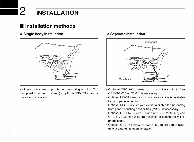
D Separate installation
• Optional OPC-600 SEPARATION CABLE (3.5 m; 11.5 ft) orOPC-601 (7.0 m; 23.0 ft) is necessary.
• Optional MB-58 REMOTE CONTROLLER BRACKET is availablefor front panel mounting.
• Optional MB-65 MOUNTING BASE is available for increasingfront panel mounting possibilities (MB-58 is necessary).
• Optional OPC-440 MICROPHONE CABLE (5.0 m; 16.4 ft) andOPC-647 (2.5 m; 8.2 ft) are available to extend the micro-phone cable.
• Optional OPC-441 SPEAKER CABLE (5.0 m; 16.4 ft) is avail-able to extend the speaker cable.
INSTALLATION2
9
Installation methodsD Single body installation
• It is not necessary to purchase a mounting bracket. Thesupplied mounting bracket (or optional MB-17A) can beused for installation.
Main body
Front panel

2INSTALLATION
10
LocationSelect a location which can support the weight of the trans-ceiver and does not interfere with driving in any way. We rec-ommend the locations shown in the diagram below.
Single body installation➀ Drill 4 holes where the mounting bracket is to be installed.
• Approx. 5.5–6 mm (3⁄16 in) when using nuts; approx. 2–3 mm (1⁄16
in) when using self-tapping screws.
➁ Insert the supplied screws, nuts and washers through themounting bracket and tighten.
➂ Adjust the angle for the clearest view of the function dis-play.
NEVER place the transceiver or remote controller wherenormal operation of the vehicle may be hindered or whereit could cause bodily injury.NEVER place the transceiver or remote controller whereair bag deployment may be obstructed.DO NOT place the transceiver or remote controller wherehot or cold air blows directly onto it.AVOID placing the transceiver or remote controller in di-rect sunlight.
• EXAMPLE INSTALLATION LOCATIONS
Nut
Spring washer
Springwasher
When usingself-tappingscrews
Flat washerMountingbracket
Flangebolt
20°

2 INSTALLATION
11
Microphone connectionThe microphone connector is located behind the front panel.Connect the supplied microphone as follows:
➀ Slide the supplied microphone cable connector (and at-tached microphone) into the microphone jack on the mainbody of the transceiver until it clicks into place.
➁ To remove the microphone, push the release lever on thebottom of the microphone cable connector.
Separate installationUsing an optional OPC-600/601 SEPARATION CABLE, the frontpanel can be separated from the main body, doubling as a re-mote controller.
➀ Detach the front panel asat right.
➁ Connect a separationcable between the frontpanel and main bodyusing the supplied screwsas illustrated below.
Connect microphonehere
Rear of front panel Main body
OPC-600 or OPC-601
➀ 8 V OUT➁ Freq. up/down➂ 8 V control IN➃ PTT➄ Mic AF (–)➅ Mic AF (+)➆ Ground➇ Data IN
➇➀
Microphone pin assignments

2INSTALLATION
12
Optional MB-58 installationThe optional MB-58 REMOTE CONTROLLER BRACKET is avail-able for separate installation.
➀ Drill 2 or 4 holes where the bracket or mounting base is tobe installed, respectively.• Approx. 4 mm (1⁄8 in) when using nuts; approx. 1–2 mm (1⁄16 in)
when using self-tapping screws.
➁ Insert the supplied screws, bolts and washers through themounting base and tighten.
➂ Adjust the angle for the clearest view of the function dis-play and tighten 2 screws when the mounting base is used.
BracketWhen using self-tapping screws.
Mountingbase
Mountingbolt
➃ Attach the supplied Velcro pads (large) to the remote con-troller and bracket.
➄ Attach the supplied Velcro pad (small) or rubber pad to thebracket as shown below; then attach the remote controller.
D When using the MB-65
MB-58 IC-207H remote controller
MB-58
MB-65
Adjust the viewingangle for maximumvisibility of the func-tion display.

2 INSTALLATION
13
Battery connection DC power supply connectionUse a 13.8 V DC power supply with more than 12 A capabil-ity. An optional IC-PS30 DC POWER SUPPLY is available forusing the transceiver with a DC power supply in your home.
Make sure the ground terminal of the DC power supply isgrounded.
NEVER connect the transceiver directly to a 24 V battery.DO NOT use the cigarette lighter socket for power con-nections.Attach a rubber grommet when passing the DC powercable through a metal plate to prevent short circuits.
• CONNECTING TO A DC POWER SOURCESee p. 69 for fuse replacement.
Fuses20 A
blackred⊕
red
Grommet
⊕
−
black−
12 VSuppliedDC power cable
• CONNECTING TO A DC POWER SUPPLYSee p.69 for fuse replacement.
DC powersupply 13.8 V
to anACoutlet
Fuses20 Ablack
red⊕−
⊕−

2INSTALLATION
14
Antenna installationD Antenna locationTo obtain maximum performance from the transceiver, selecta high-quality antenna and mount it in a good location. A non-radial antenna should be used when using a magnetic mount.
D Antenna splitterYou can use a dual band antenna because a duplexer is in-stalled in the transceiver. However, an external duplexer mustbe connected when using a separate antenna for each band.
D Antenna connectorThe antenna uses a PL-259 connector.
30 mm
10 mm (soft solder)
10 mm
1–2 mm
solder solder
Softsolder
Coupling ring
• PL-259 CONNECTOR
➀
➂
➃
➁
Slide the coupling ring down. Strip the cable jacket and soft solder.
Slide the connector body on and solder it.
Screw the coupling ring onto the connec-tor body.
Strip the cable as shown at right. Soft solder the center con-ductor.
(10 mm ≈ 3⁄8 in)
Roof-mount antenna(Drill a hole or use a magnetic mount.)
Gutter-mount antenna
Trunk-mountantenna

SETTING A FREQUENCY3
15
PreparationD Turning power ON/OFFPush [PWR] for 1 sec. to turn power ON or OFF.
D Operating bandThe IC-207H can receive/transmit on the 144 MHz and430(440) MHz bands, or receive only on the avionics band(USA version only).
Push [BAND] one or more times to select the desired operat-ing band.• The frequency changes to indicate the selected band.• The operating band cannot be changed unless you are in VFO
mode (see right).
Push [BAND] one or more times to select the de-sired operating band.
D VFO and memory modesThe transceiver has 2 normal operating modes: VFO modeand memory mode.
Push [V/MHz] to select VFO mode when the transceiver isnot in VFO mode.• If VFO mode is already selected, the digits below 100 kHz disap-
pear. In this case, push [V/MHz] again (or push twice depending onversion).
Push [VFO] to select VFO mode.
Push [PWR] for 1 sec.
BAND
Appears when memory modeis selected.
VFO mode is selected.
H I 195 H I 1
95
d
VFO

3SETTING A FREQUENCY
16
Lock functionsTo prevent accidental frequency changes and unnecessaryfunction access, use the lock function. The transceiver has 2different lock functions.
D Frequency lockThis function locks the tuning dial and switches electronicallyand can be used together with the microphone lock function.
Push and hold until “L” appears in the memory chan-nel readout to activate the function.• To cancel the function, push and hold until “L” disappears.• [PTT], [MONI], [VOL] and [SQL] can be used while the frequency
lock function is in use. Also, TONE-1, TONE-2, DTMF tones orDTMF memory contents can be transmitted from the microphone.
Push and hold [(VFO)LOCK] for 1 sec. to togglethe function ON and OFF.
LOCK
LOCK
D Microphone keypad lockThis function locks the microphone keypad.
Push [FUNC] then [A16 KEYLOCK] to togglethe microphone keypad lock function ON andOFF.• [PTT] and the 7 keys on the upper half of the mi-
crophone can be used.• All switches on the transceiver can be used.• The keypad lock function is released when the
power is turned OFF then ON again.
“L” appears while the frequency lock function is in use.
H I 195
LOCK
16 KEY LOCK#

3 SETTING A FREQUENCY
17
Using the tuning dial➀ Push [BAND] to select the desired band, if necessary.➁ Rotate the tuning dial to set the frequency.
• If VFO mode is not selected, push the [V/MHz] to select VFOmode.
• Frequency changes according to the selected tuning steps.(p. 18)
➂ For the 1 MHz frequency setting, rotate the tuning dial afterpushing [V/MHz].• Pushing [V/MHz] for 1 sec. starts a scan function. If this happens,
push [V/MHz] again to stop the scan.
Using [Y]/[Z] switchesPush [Y] or [Z] to set the selected band’s fre-quency.• If VFO mode is not selected, push [VFO] to select it.• Frequency changes according to the selected tuning
steps. (p. 18)• Pushing [Y] or [Z] for more than 0.5 sec. activates a
scan. If this happens, push [Y] or [Z] again to stop it.
NOTE: 1 MHz steps cannot be used via the [Y]/[Z]switches.
The display shows that the 1 MHztuning step is selected for theVHF band.
H I 195
YZ

3SETTING A FREQUENCY
18
Tuning step selectionTuning steps are the minimum frequency change incrementswhen you rotate the tuning dial or push the [Y] or [Z]switches on the microphone. The following tuning steps areavailable:
• 5 kHz • 10 kHz • 12.5 kHz • 15 kHz• 20 kHz • 25 kHz • 30 kHz • 50 kHz
NOTE: For convenience, select a tuning step thatmatches the frequency intervals of repeaters in your area.
➀ Push [BAND] to select the desired band, if necessary.➁ Push [V/MHz] to select VFO mode if another mode has
been selected.➂ Push [SET] one or more times until “tS” appears as shown
below.• Pushing [MONI] reverses the order of selection.• Cancel the DTMF memory function in advance. (p. 48)
➃ Rotate the tuning dial to select the tuning step.➄ Push [V/MHz] to exit set mode.
Ä Push [BAND] to select the operating band, ifnecessary.
Å Push [VFO] to select VFO mode.Ç Push [FSET] one or more times until “tS” ap-
pears as shown previously.• Push [ENT] to reverse the order of selection.• Cancel the DTMF memory function in advance.
(p. 48)
É Push [Y] or [Z] to select the tuning step.Ñ Push [CLR] to exit set mode.
USING SET MODE
25 kHz tuning step15 kHz tuning step
H I 195 H I 1
95
SETB

3 SETTING A FREQUENCY
19
Using the keypadThe frequency can be directly set via numeralkeys on the microphone.
Ä Push [BAND] to set the operating band, if necessary.Å Push [VFO] to select VFO mode.Ç Push [ENT] to activate the keypad for digit input.
É Push 5 keys to input a frequency.• When a digit is mistakenly input, push [ENT] to clear the input,
then input from the 1st digit.• Pushing [CLR] clears input digits and retrieves the frequency.
Ñ Push [Y] or [Z] to make adjustments below the 10 kHzdigit, if desired.
[EXAMPLE]: Setting the frequency to 145.360 MHz.
[EXAMPLE]: Setting the frequency to 446.325 MHz. (When the 25 kHz tuning step is selected in UHF.)
BAND then VFO CENT 3PRIO5MID1MONI 4HIGH 6LOW
195 1
95 195 1
95
195 1
95 195 1
95 195
BAND then VFO CENT 3PRIO6LOW4HIGH 4HIGH 0VOL
ENTC

BASIC OPERATION 4
20
Receiving➀ Push [PWR] for 1 sec. to turn power ON.➁ Push [BAND] to select a band.➂ Set the audio level.
Push [MONI] to open the squelch. Rotate the [VOL] control to adjust the audio output level. Push [MONI] again to close the squelch.
➃ Set the squelch level. Rotate [SQL] fully counterclockwise in advance. Rotate [SQL] clockwise until the noise just disappears. When interference is received, rotate [SQL] clockwise
again for attenuator operation.➄ Set the operating frequency. (pgs. 15–19)➅ When receiving a signal on the set frequency, squelch
opens and the transceiver emits audio.• “BUSY” appears and the S/RF indicator shows the relative signal
strength for a received signal.
When receiving a signal on VHF.
BUSYH I 1
95
The volume and squelch levels can be adjusted via the mi-crophone. However, levels return to the front panel settingwhen power is turned OFF or a front panel control is adjusted.
Ä Push [PWR] on the transceiver for 1 sec. to turnpower ON.
Å Set the audio levels. Select the desired band. Push [➀MONI], then push [BZVOL] or
[IYVOL] to adjust the audio level. Push [➀MONI] again to close the squelch.
Ç Set the squelch level using [AZSQL] or[HYSQL], if desired.
É Set the operating frequency. (pgs. 15–19)
CONVENIENTRF attenuator: The transceiver has an RF attenuator relatedto the [SQL] setting. The attenuator is automatically activatedwhen [SQL] is rotated further than the 12 o’clock position.Approx. 10 dB attenuation is obtained at full rotation.
Appears while setting volume Appears while setting squelch
BUSYH I 1
95 H I 195
BAND
VOL
VOL

4 BASIC OPERATION
21
Avionics band receive (U.S.A. version only)
AM mode can be selected over the range of 118.000 to135.995 MHz for reception of avionics-related broadcasts.
➀ Push [BAND] one or more times to select the aviationband.
➁ Push and hold [BAND] to toggle between AM and FMmodes.• Mode selection cannot be performed via the microphone.
CONVENIENTThe tuning steps for the avionics band are available sepa-rately from those for other ranges.
Appears when AM mode is selected.
H I 195
Monitor functionThis function is used to listen to weak signals without disturb-ing the squelch setting or to open the operating band’ssquelch manually even when mute functions such as tonesquelch are in use.
Push [MONI] to open the operating band’s squelch.• Push [MONI] again to cancel the function.• While duplex is ON for repeater operation, the transmitting fre-
quency can be monitored with [MONI].
Ä Push [BAND] to change bands, if necessary.Å Push [➀MONI] to open the operating band’s
squelch.• Push [➀MONI] again to cancel the function.
Audio mute functionThis function mutes the operating band’s audiowithout disturbing the volume setting.
Ä Push [FUNC] then [HMUTE] to mute the operating band’saudio signals• “MUTE” appears.
Å Push [ECLR] (or any other key) to cancel the function.• “MUTE” disappears.
MONI➀
MUTEH

4BASIC OPERATION
22
TransmittingCAUTION: Transmitting without an antenna may dam-age the transceiver.
NOTE: To prevent interference, listen on the frequency be-fore transmitting by pushing [MONI] or [➀MONI] on the mi-crophone.
➀ Push [BAND] one or more times to select the operatingband.
➁ Set the operating frequency. (pgs. 15–19)• Select output power if desired. See section at right for details.
➂ Push and hold [PTT] to transmit.• “$” appears.• The S/RF indicator shows the output power selection.• The operating frequency, etc. are automatically programmed into
a scratch pad memory. See p. 36 for details.• One-touch PTT function is available. See p. 23 for details.
➃ Speak into the microphone using your normal voice level.• DO NOT hold the microphone too close to your mouth or speak
too loudly. This may distort the signal.➄ Release [PTT] to return to receive.
Selecting the output powerThe transceiver has 4 output power levels to suit your oper-ating requirements. Low output powers during short-distancecommunications may reduce the possibility of interference toother stations and will reduce current consumption.
➀ Push [BAND] one or more times to select the operatingband.
➁ Push [LOW] one or more times to select the desired out-put power.• The output power can be changed while transmitting.
POWERSELECTION S/RF INDICATOR VHF UHF
HI 50 W 35 W
MID-HI 20 W 20 W
MID-LO 10 W 10 W
LO 5 W 5 W
195
195
195
195

4 BASIC OPERATION
23
The microphone can select the desired outputpower directly.
Ä Push [BAND] to select the desired band, if nec-essary.
Å Push [➃HIGH] for high output power; [➄MID] formid-high output power; [➅LOW] for low outputpower.
• “MID-LO” output power CANNOT be selected viathese microphone keys, however, the default settingfor [F-1] is output power selection—“MID-LO” outputpower CAN be selected using [F-1], in this case.
• The output power CANNOT be changed via the mi-crophone while transmitting.
One-touch PTT functionThe PTT switch can be operated as a one-touchPTT switch (each push toggles transmit/receive).Using this function, you can transmit without push-ing and holding the PTT switch.
To prevent accidental, continuous transmissionswith the one-touch PTT function, the transceiverhas a time-out timer. See p. 59 for details.
Ä Push [FUNC] then [➂PTT-M] to turn the one-touch PTTfunction ON.• The activity indicator lights green.
Å Push [PTT] to transmit and push again to receive.• Two beeps sound when transmission is started and a long beep
sounds when returning to receive.• “$” flashes while transmitting with the one-touch PTT func-
tion.
Ç Push [FUNC] then [➂PTT-M] to turn the one-touch PTTfunction OFF.• The activity indicator goes out.
HIGH4
MID5
LOW6
PTT-M3

REPEATER OPERATION 5
24
Accessing a repeater➀ Push [BAND] one or more times to select the desired band.➁ Set the receive frequency (repeater output frequency).
(pgs. 15–19)➂ Push and hold for 1 sec., one or more times, to se-
lect – duplex or + duplex.• “DUP –” or “DUP” appears to indicate the transmit frequency for
minus shift or plus shift, respectively.• When the auto repeater function is turned ON, (available for the
U.S.A. version only), steps ➁, ➂ are not necessary. (p. 31)
➃ Push [TONE] one or more times to turn ON the subaudibletone encoder, according to repeater requirements.• Refer to p. 26 for tone frequency settings.• When the repeater requires a different tone system, see the page
at right.
➄ Push and hold [PTT] to transmit.• The displayed frequency automatically changes to the transmit
frequency (repeater input frequency).• The operating condition is automatically programmed into a
scratch pad memory. See p. 36 for details.
DUP
• If “oFF” appears, confirm the offset frequency. (p. 27)
➅ Release [PTT] to receive.➆ Push [MONI] to check whether the other station’s transmit
signal can be directly received or not.➇ To return to simplex, push for 1 sec., once or twice,
to clear the “DUP” indicator.➈ To turn OFF the subaudible tone encoder, push [TONE]
one or more times until no tone indicators appear.
DUP
DUPH I 1
95T
DUPH I 1
95T

5 REPEATER OPERATION
25
Ä Push [BAND] to select the desired band, if nec-essary.
Å Set the receive frequency (repeater output fre-quency). (pgs. 15–19)
Ç Push [➆DUP–] to select – duplex; push[➇DUP+] for + duplex.
É Push [FUNC] then [➆TONE] to turn ON thesubaudible tone encoder according to repeaterrequirements.• Refer to p. 26 for tone frequency setting.
• When the repeater requires a different tone system,
see at right.
Ñ Push and hold [PTT] to transmit.Ö Push and hold [➀MONI] to check whether the
other station’s signal can be directly received.Ü Release [PTT] to receive.á To return to simplex operation, push [➈SIMP].à To turn OFF the subaudible tone encoder, push
[FUNC], then [GT-OFF].
D DTMF tonesPush [DTMF-S], then push the keys of the desiredDTMF digits.• The function indicator lights green.• 0–9, A–D, M(E) and #(F) are available.• Cancel the DTMF memory encoder function in ad-
vance. (p. 48)• Push [DTMF-S] again to return the keypad to normal
function control.• The transceiver has 14 DTMF memory channels for
autopatch operation. See p. 46 for details.
D 1750 Hz toneA 1750 Hz tone is required to access most European re-peaters. The microphone has 1750 Hz tone capability.
Ä Push [FUNC].• The mode indicator lights orange.
Å Push [BTONE-1] to transmit a 1750 Hz tonecall signal for 0.5 sec.; push and hold [ITONE-2] to transmit a 1750 Hz tone call signal for anarbitrary period.
• The mode indicator goes out automatically.• The optional HM-90 also has 1750 Hz tone capability.
TONE-1
TONE-2
DUP–7
DUP+8
SIMP9
DTMF S

5REPEATER OPERATION
26
Subaudible tones
➀ Push [BAND] to select the desired band.➁ Select the mode/channel you wish to set the subaudible
tone frequency to, such as VFO mode or memory/callchannel.
➂ Push [SET] one or more times until “T” and “rT” appearsfor repeater use; or until “T SQL” and “CT” appears for tonesquelch or pocket beep use.• Push [MONI] to reverse the order of selection.• Cancel the DTMF memory encoder function in advance. (p. 48)
➃ Rotate the tuning dial to select and set the desired fre-quency.
➄ Push [V/MHz] to exit set mode.
NOTE: The subaudible tone frequency can be set in amemory channel temporarily. However, the set contentsare cleared once the memory/call mode is selected. Tostore the tone frequency permanently, overwrite the chan-nel information.
USING SET MODE
Separate setting for each band
The display shows that an 88.5 Hz subaudible tone frequency is set for re-peater use.
TH I 1
95
Ä Push [BAND] to select the desired band, if nec-essary.
Å Set the mode/channel you wish to set the sub-audible tone frequency to, such as VFO mode,memory/call channel or scratch pad memory.• The subaudible tone frequency is independently pro-
grammed into each mode or channel.
Ç Push [FSET] one or more times until “T” and“rT” appears for repeater use; or until “T SQL”and “CT” appears for tone squelch or pocketbeep use.• Pushing [GENT] reverses the order of selection.• Cancel the DTMF memory encoder function in ad-
vance. (p. 48)
É Push [Y] or [Z] to select and set the desiredfrequency.• Pushing and holding [Y] or [Z] changes the fre-
quency continuously.
Ñ Push [ECLR] to exit set mode.
• Subaudible tone frequency list (unit: Hz)67.0 79.7 94.8 110.9 131.8 156.7 171.3 186.269.3 82.5 97.4 114.8 136.5 159.8 173.8 189.971.9 85.4 100.0 118.8 141.3 162.2 177.3 192.874.4 88.5 103.5 123.0 146.2 165.5 179.9 196.677.0 91.5 107.2 127.3 151.4 167.9 183.5 199.5
203.5206.5210.7218.1225.7
229.1233.6241.8250.3254.1
SETB
5 REPEATER OPERATION
27
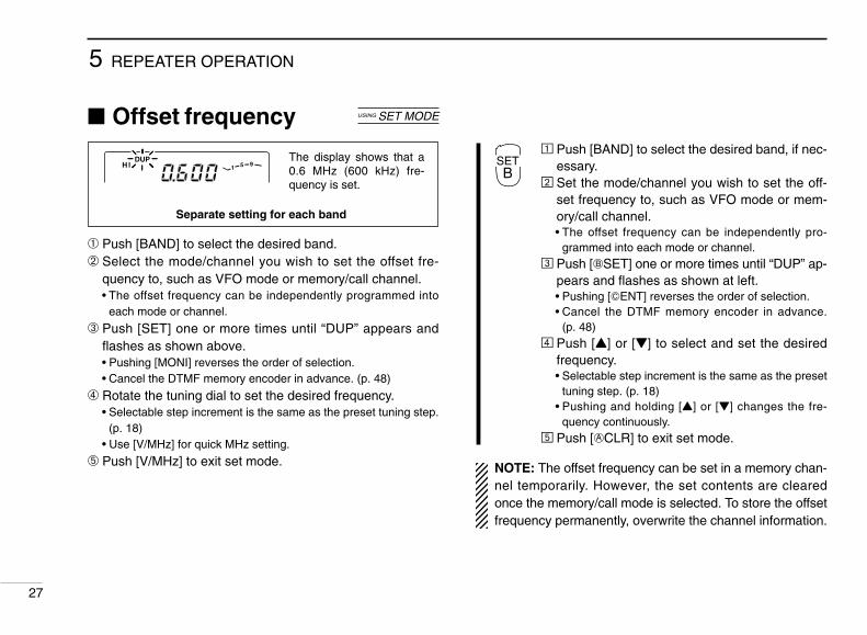
Offset frequency
➀ Push [BAND] to select the desired band.➁ Select the mode/channel you wish to set the offset fre-
quency to, such as VFO mode or memory/call channel.• The offset frequency can be independently programmed into
each mode or channel.
➂ Push [SET] one or more times until “DUP” appears andflashes as shown above.• Pushing [MONI] reverses the order of selection.• Cancel the DTMF memory encoder in advance. (p. 48)
➃ Rotate the tuning dial to set the desired frequency.• Selectable step increment is the same as the preset tuning step.
(p. 18)• Use [V/MHz] for quick MHz setting.
➄ Push [V/MHz] to exit set mode.
USING SET MODE
Separate setting for each band
The display shows that a 0.6 MHz (600 kHz) fre-quency is set.
H I 195
DUPÄ Push [BAND] to select the desired band, if nec-
essary.Å Set the mode/channel you wish to set the off-
set frequency to, such as VFO mode or mem-ory/call channel.• The offset frequency can be independently pro-
grammed into each mode or channel.Ç Push [FSET] one or more times until “DUP” ap-
pears and flashes as shown at left.• Pushing [GENT] reverses the order of selection.• Cancel the DTMF memory encoder in advance.
(p. 48)É Push [Y] or [Z] to select and set the desired
frequency.• Selectable step increment is the same as the preset
tuning step. (p. 18)• Pushing and holding [Y] or [Z] changes the fre-
quency continuously.Ñ Push [ECLR] to exit set mode.
NOTE: The offset frequency can be set in a memory chan-nel temporarily. However, the set contents are clearedonce the memory/call mode is selected. To store the offsetfrequency permanently, overwrite the channel information.
SETB

D Frequency range and offset direction
5REPEATER OPERATION
28
Auto repeater(U.S.A. version only)
The U.S.A. version automatically activates the repeater set-tings (DUP or DUP– and tone encoder ON/OFF) when theoperating frequency falls within the general repeater outputfrequency range and deactivates them when outside of therange.
D Setting the auto repeater function ON/OFF➀ Push [PWR] to turn power OFF.➁ While pushing [SET] (far right switch), turn power ON to
enter initial set mode.➂ Push [SET] one or more times until the “rPt” display ap-
pears as shown below.
➃ Rotate the tuning dial to turn the auto repeater function to“r1,” “r2” or OFF.• “r1”: auto repeater is ON, tone encoder is OFF;
“r2”: auto repeater is ON, tone encoder is ON.
➄ Push [PWR] momentarily to exit initial set mode.
USING INITIAL SET MODE
FREQUENCY RANGE DUPLEX DIRECTION145.200–145.495 MHz146.610–146.995 MHz
“DUP–” appears
147.000–147.395 MHz “DUP” appears
442.000–444.995 MHz “DUP” appears
447.000–449.995 MHz “DUP–” appears
TDUP
Auto repeater function isturned OFF
Auto repeater function is ON,tone encoder is OFF.

MEMORY OPERATION6
29
General descriptionThe transceiver has 150 regular memory channels, 10 scanedge memory channels (5 pairs) plus 2 call channels (by de-fault C1 is for VHF and C2 is for UHF, however both can beset to VHF or both to UHF as desired); each of these can beindividually programmed with the following data.
• Operating frequency (pgs. 15–19)• Duplex direction (DUP or DUP–) and its offset frequency
(pgs. 24, 25, 27)• Subaudible tone encoder or tone squelch and its tone fre-
quency (pgs. 24–26)• Skip information* (p. 42)*Except for the scan edge memory channels.
Memory channel selectionD Using the tuning dial➀ Push [M/CALL] once or twice to display “!”.➁ Rotate the tuning dial to select the desired memory chan-
nel.• Only programmed memory channels can be selected.
D Using [Y]/[Z] switchesÄ Push [BAND] to select the desired band, if nec-
essary.Å Push [MR] to select memory mode.Ç Push [Y] or [Z] several times to select the de-
sired memory channel.• Pushing [Y]/[Z] more than 0.5 sec. activates a scan.• If a scan is activated, push [Y] or [Z] again to stop it.
D Using the keypadÄ Push [BAND] to select the desired band, if nec-
essary.Å Push [MR] to select memory mode.Ç Push [GENT] to activate the keypad for nu-
meral input.É Push 2 appropriate digit keys to input a chan-
nel number.• When inputting non-programmed channel numbers
the previous memory channel appears.• To select scan edge channels, “B” and “A” can be
used for A and b respectively.
MR
YZ
MR
ENTC
6MEMORY OPERATION
30
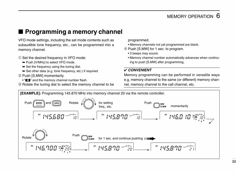
Programming a memory channelVFO mode settings, including the set mode contents such assubaudible tone frequency, etc., can be programmed into amemory channel.
➀ Set the desired frequency in VFO mode: Push [V/MHz] to select VFO mode. Set the frequency using the tuning dial. Set other data (e.g. tone frequency, etc.) if required.
➁ Push [S.MW] momentarily.• “!” and the memory channel number flash.
➂ Rotate the tuning dial to select the memory channel to be
programmed.• Memory channels not yet programmed are blank.
➃ Push [S.MW] for 1 sec. to program.• 3 beeps may sound.• Memory channel number automatically advances when continu-
ing to push [S.MW] after programming.
CONVENIENTMemory programming can be performed in versatile wayse.g. memory channel to the same (or different) memory chan-nel, memory channel to the call channel, etc.
[EXAMPLE]: Programming 145.870 MHz into memory channel 20 via the remote controller.
Push and Rotate for settingfreq., etc.
Rotate
Pushmomentarily
Pushfor 1 sec. and continue pushing
M
H I 195 H I 1
95
H I 195 H I 1
95
H I 195
BAND MWS.MW
MWS.MW
M
H I 195
VFO

6 MEMORY OPERATION
31
Programming a memory channel via the microphoneMemory channel programming can be performedvia the microphone.
Ä Push [BAND] to select the desired band, if necessary.Å Set the desired frequency in VFO mode:
Push [VFO] to select VFO mode. Set the frequency using the keypad. Set other data (e.g. offset frequency, duplex direction, subaudi-
ble tone encoder ON/OFF and its frequency), if required.
Ç Push [FUNC] then [EMW] momentarily.É Select the memory channel to be programmed:
Push [Y] or [Z] to select the memory channel (direct numeralinput cannot be used).
Ñ Push [FUNC] then [EMW] for 1 sec. to program. 3 beeps may sound and the VFO contents (including the sub-
audible tone frequency, etc.) are programmed. Memory channel number advances when continuing to push
[MW] after programming.
[EXAMPLE]: Programming 145.870 MHz into memory channel 20 via the microphone.
Push , Push thenmomentarily
PushPush for 1 sec. and continue pushing
BAND VFO
8DUP+ 7DUP
5MID1MONI 4HIGH
CENT
MW
FUNC ACLR
thenMW
FUNC ACLR
M
H I 195 H I 1
95
H I 195 H I 1
95
H I 195
M
H I 195
MW

6MEMORY OPERATION
32
Transferring memorycontents
This function transfers a memory channel’s contents into aVFO (or another memory/call channel). This is useful whensearching for signals around a memory channel frequencyand for recalling the offset frequency, subaudible tone fre-quency, etc.
➀ Push [BAND] one or more times to select a band.➁ Select the memory channel to be transferred:
Select memory mode by pushing [M/CALL] once or twice (“!”appears).
Rotate the tuning dial to select the memory channel.
➂ Push [S.MW] momentarily, then rotate the tuning dial to se-lect another memory channel to transfer.• To transfer to the VFO, push and hold [(S.MW)MW] instead of
pushing momentarily.
➃ Push and hold [(S.MW)MW] to transfer when a momentarypush was used in the previous step.
Push
+
for 1 sec.
MW
FUNC ACLR
MWS.MW
TDUPH I
M1
95TDUP
H I 195
Ä Push [BAND] to select the desired band, if nec-essary.
Å Select the memory channel to be transferred: Push [MR] to select memory mode. Push [Y] or [Z] to select the memory channel; or
push [GENT] then push the desired memory chan-nel number (2 digits) to select the memory chan-nel directly.
Ç Push [FUNC] then [EMW] momentarily, thenpush [Y] or [Z] to select another memorychannel to transfer.• To transfer to the VFO, push [FUNC] then push and
hold [EMW] instead of pushing momentarily.
É Push [FUNC] then [EMW] for 1 sec. to transferwhen a momentary push was used in the previ-ous step.
MW

6 MEMORY OPERATION
33
Memory clearingContents of programmed memories can be cleared (blanked),if desired.
➀ Push [S.MW] momentarily.➁ Select the memory channel to be cleared with the tuning
dial.➂ Push [S.MW] briefly, then a second time for 1 sec.
• 3 beeps sound, then the frequency is cleared.• “!” flashes continuously.• Scan edges and call channels cannot be cleared.
➃ Push any switch to stop the flashing.
[EXAMPLE]: Clearing memory channel 20.
NOTE:Be careful—the contents of cleared memories CANNOTbe recalled.• Scan edge channels 1A/1b cannot be cleared.
Memory clearing may not be performed from themicrophone.
Push Rotatemomentarily
again for 1 sec. Push
briefly, then pushPush any switch
H I 195
H I 195
MWS.MW
MWS.MW
MWS.MW
M
H I 195
M
H I 195
M
H I 195

CALL CHANNEL OPERATION 7
34
Calling up a call channelEach band has an independent call channel to store a most-often-used frequency for quick recall.
➀ Push [BAND] one or more times to select a band, if nec-essary.
➁ Push [M/CALL] once or twice to display a large “C” in thememory channel readout.• While a call channel is displayed, pushing [BAND] toggles be-
tween the 2 call channels.
➂ Push [V/MHz] or [M/CALL] to exit the call channel.
Ä Push [BAND] to select the desired band, if nec-essary.
Å Push [(MR)CALL] for 1 sec. to select the callchannel.
Ç Push [BAND] to toggle between the 2 callchannels.
Transferring call channelcontents
➀ Push [BAND] to select a band, if necessary.➁ Select the call channel by pushing [M/CALL] once or twice.
• “C1” or “C2” appears—push [BAND] to toggle between them.➂ Push [S.MW] momentarily, then rotate the tuning dial to se-
lect another memory channel to transfer.• To transfer to the VFO, push and hold [(S.MW)MW] instead of
pushing momentarily.➃ Push and hold [(S.MW)MW] to transfer when a momentary
push was used in the previous step.
Ä Push [BAND] to select the desired band, if nec-essary.
Å Push [(MR)CALL] for 1 sec. to select a callchannel, then push [BAND] to select the othercall channel, if desired.
Ç Push [FUNC], then [EMW] momentarily.• To transfer to the VFO, push [FUNC] then [EMW] in-
stead of pushing [EMW] momentarily.
É Push [FUNC] then [EMW] for 1 sec. to transferwhen momentarily pushing [EMW] in step Ç.
Large “C” shows a call channel is selected.
Small “c” shows VFO mode was selected from a call channel.
H I 195 H I 1
95
CALL
MWA

7 CALL CHANNEL OPERATION
35
Programming a call channelIn addition to an operating frequency, duplex information andsubaudible tone information (tone encoder or tone squelchON/OFF and its frequency) can be programmed into a callchannel.
➀ Push [BAND] to select a band, if necessary.➁ Select the call channel by pushing [M/CALL] once or twice.
( “C1” or “C2” appears); then push [BAND] to change thecall channel, if desired.
➂ Set the desired frequency in VFO mode: Push [VFO] to select VFO mode. Set the frequency using the keypad. Set other data (e.g. offset frequency, duplex direction, subaudi-
ble tone encoder ON/OFF and its frequency), if required.
➃ Push [(S.MW)MW] for 1 sec. to program.
[EXAMPLE]: Programming 145.120 MHz into the VHF call channel via the microphone.
CONVENIENTThe call channel can also be programmed from the VFO di-rectly (similar to memory programming).
Ä Push [BAND] to select the desired band, if nec-essary.
Å Push [(MR)CALL] for 1 sec. to select a callchannel, then push [BAND] to change the callchannel, if desired.
Ç Set the desired frequency in VFO mode:• Push [VFO] to select VFO mode.• Set the desired frequency using the keypad.• Set other data, if required.
É Push [FUNC] then [EMW] for 1 sec. to pro-gram.
H I 195 H I 1
95
BAND VFO 2SCAN
5MID
1MONI
1MONI
4HIGH
CENT MW
FUNC ACLR
CALL
MRCall channel VFO mode then
for 1 sec.for 1 sec.
BeepBeepBeep
H I 195 H I 1
95
MWA

SCRATCH PAD MEMORY 8
36
What is a scratch padmemory?
During VFO operation, the transceiver automatically memo-rizes operating frequency information, separate from regularmemory channels, when transmitting on a new frequency.The 5 previously operated frequencies for each band can berecalled (L1 to L5 appear for simplex frequencies; r1 to r5 ap-pear for duplex frequencies.
NOTE: When memory mode is selected, the frequency isnot programmed into a scratch pad.
Calling up a scratch padmemory
➀ Select the call channel by pushing [M/CALL] once or twice.(A large “C” appears.)• To transmit on the scratch pad memory, select the desired band
in advance.
➁ Rotate the tuning dial to select a scratch pad memory.• Previously transmitted frequency and one of “L1–L5” appears for
simplex memories (rotate [DIAL] left); one of “r1–r2” appears forduplex memories (rotate [DIAL] right).
• When first applying power or after CPU resetting, scratch padmemories contain no data and therefore cannot be accessed.
➂ Push [V/MHz] or [M/CALL] to exit the scratch pad memory.
• The 5th scratch pad memory will be cleared when trans-mitting on a new frequency. If the transmit frequency isalready stored in a scratch pad memory, the scratch padmemory is not cleared but the order is changed.
• When transmitting on a scratch pad memory, the scratchpad memory becomes the 1st scratch pad memory andthe order is changed.
Newest
Oldest
The oldest written frequency is cleared.
Order is changed if transmitting on this channel.
H I 195
H I 195
H I 195
H I 195
H I 195
H I 195

8 SCRATCH PAD MEMORY
37
➀ Push [BAND] to select a band, if necessary.➁ Select a call channel by pushing [M/CALL] once or twice.
• A large “C” appears.
➂ Rotate the tuning dial to select the desired scratch padmemory.• One of “L1”–“L5” appears.
➃ Push [(S.MW)MW] momentarily.• “ ” flashes to indicate VFO as the transferring channel.
➄ Rotate the tuning dial to select the desired memory chan-nel if required.
➅ Push and hold [(S.MW)MW] to transfer.
Ä Push [BAND] to select the desired band, if nec-essary.
Å Push [(MR)CALL] for 1 sec. to select the callchannel.
Ç Push [Z] one or more times to select the de-sired scratch pad memory.
É Push [FUNC] then [EMW] momentarily.• “ ” flashes to indicate VFO as the transferring
channel.
Ñ Push [Y] or [Z] to select the desired memorychannel if required.
Ö Push [FUNC] then [EMW] for 1 sec. to transfer.
Ä Push [BAND] to select the desired band, if nec-essary.
Å Push and hold [(MR)CALL] to select a call chan-nel.
Ç Push [Z] one or more times to select a duplexscratch pad memory.• Once entering a scratch pad memory, [Y] can also
be used for selection.
É Push [MR] or [VFO] to exit the scratch padmemory.
Transferring scratch padmemory contents
Transferring scratch pad memory contents to the VFO is donesimilarly to transferring regular memory/call channel contents.
Push for 1 sec.
thenMW
FUNC ACLR
MWS.MW
H I 195 1
95H I
CALL
MW

SCAN OPERATION 9
38
FULL SCAN Repeatedly scans all fre-quencies over the entire band. Used as the simplest scan without any prelimi-nary settings necessary.
PROGRAMMED SCAN Repeatedly scans between two user-programmed fre-quencies. Used for check-ing for frequencies within a specified range such as repeater output frequen-cies, etc. 5 pairs of scan edges are available.
SCAN RESUME CONDITION 5 resume conditions are available: 3 timer scans, pause scan and empty scan. When receiving a signal, pause scan pauses until the signal disappears; timer scans pause for 5, 10 or 15 sec. Empty pause scan pauses until a signal appears.
MEMORY SCAN Repeatedly scans memory channels except for skip channels. Used for often-called channels and by-passing normally busy channels such as repeater frequencies.
Band edge
Band edge
Scan
Jump
Band edge
Band edge
Scan
Jump
Scan edges
SKIP
SKIP
M 1 M 5
M 2 M 3 M 4
M 6M 150 M 7
Pausescan
Receivinga signal
Timerscan
Emptypausescan
Pausing
Pausing
2 sec.
2 sec.
Scan typesScanning searches for transmitted signals automatically andmakes it easier to locate new stations for contact or listeningpurposes.
Each band has 3 scan types and 5 resume conditions to suityour needs.

9 SCAN OPERATION
39
Scan start/stopD Pre-operation• Common setting: scan resume condition. (p. 43)• For programmed scan: program the scan edges. (p. 40)• For memory scan: program 2 or more memory chan-
nels; set memory skip settings, if de-sired. (p. 42)
D Operation➀ Push [BAND] to select a band, if necessary.➁ Select VFO mode for full/programmed scan with the
[V/MHz] switch; or memory mode for memory scan with the[M/CALL] switch.
➂ Set the squelch to the point where noise is muted.➃ Push for 1 sec. to start the scan.
• When the tone squelch is in use, starts a normal scan—not tone scan.
• To change the scanning direction, rotate the tuning dial.• The memory channel readout indicates the scan type as follows:
SCAN
SCAN
➄ To select the scan range while operating full/programmedscan, push [BAND] several times.
➅ To stop the scan, push [VMHz].
Ä Push [BAND] to select the desired band, if nec-essary.
Å Push [VFO] to select VFO mode for full/pro-grammed scan; or push [MR] to select memorymode for memory scan.
Ç Push [HYSQL] or [AZSQL] one or more timesto set the squelch just closed.
É Push [➂SCAN] to start the scan.• [Y]/[Z] also start the scan when pushed and held.
Ñ To select the scan range while operatingfull/programmed scan, push [BAND] severaltimes.
Ö To stop the scan push [ECLR].
During full scan
Pushto select full scansand scan edgepairs in sequence.
BAND
H I 195
During programmed scan
Indicates scan edge channels.• P1 stands for 1A/1b.• P1 to P5 are available when they are programmed.
H I 195
During memory scanH I
M1
95
SCAN2
BAND

9SCAN OPERATION
40
Programming scan edgesScan edges can be programmed in the same manner asmemory channels. Scan edges are programmed into pairs ofscan edge channels, 1A/1b to 5A/5b, in memory channels.
➀ Push [BAND] to select a band, if necessary.➁ Set the desired frequency in VFO mode:
Push [V/MHz] to select VFO mode. Set the frequency using the tuning dial. Set other data (e.g. offset frequency, etc.) if required.
➂ Push [S.MW] momentarily.• “!” and the memory channel number flashes.
[EXAMPLE]: Programming 145.30 MHz and 145.80 MHz for the VHF scan edges 1A and 1b.
Pushthenrotate
Rotate
Push
momentarily and hold
continue pushing
Program 1b in the same manner.
MWS.MW
PushMWS.MW
MWS.MW
H I 195
H I 195H I 1
95
BAND
H IM
195 H I
M1
95
➃ Rotate the tuning dial to select a scan edge channel (1A to5A).
➄ Push [(S.MW)MW] for 1 sec. to program.• 3 beeps may sound and the frequency is programmed.• Scan edge “x”b is automatically selected when continuing to push
[(S.MW)MW] after programming.➅ To program a frequency for the other pair of scan edges,
1b to 5b, repeat steps ➂ to ➄.• If the same frequency is programmed into both scan edges, pro-
grammed scan will not function.

9 SCAN OPERATION
41
Programming scan edges viathe microphone
Ä Push [BAND] to select the desired band, if nec-essary.
Å Set the desired frequency in VFO mode: Push [VFO] to select VFO mode. Set the frequency using the keypad.
Ç Push [FUNC] then [EMW] momentarily.É Push [Y] or [Z] to select scan edge channels.Ñ Push [FUNC] then [EMW] for 1 sec. to pro-
gram.
[EXAMPLE]: Programming 145.30 MHz and 145.80 MHz for the VHF scan edges 1A and 1b.
Push Push thenmomentarily
Program 1bin the samemanner.
PushPush for 1 sec. and continue pushing
VFO
3PRIO 0VOL
5MID1MONI 4HIGH
C
A
ENT
MW
FUNC ACLR
thenMW
FUNC CLR
Y
H I 195 H I 1
95
H I 195H I 1
95
H IM
195
H IM
195
3 beeps may sound and the VFO contents (including the sub-audible tone frequency, etc.) are programmed.
Memory channel number advances to the next scan edge chan-nel (1b to 5b) when continuing to push [EMW] after program-ming.
Ö To program a frequency for the other scan edge channel,repeat steps Å and Ñ.
MWA

9SCAN OPERATION
42
Skip channel settingThe memory skip function speeds up scanning by checkingonly desired memory channels. Set the memory channels tobe skipped or scanned as follows.
➀ Push [BAND] to select the a band, if necessary.➁ Select the memory channel to program or to cancel the
skip function on: Select memory mode by pushing [M/CALL] once or twice. Rotate the tuning dial to select the memory channel.
➂ Push [SET] one or more times until “CHS” appears asshown above.• Pushing [MONI] reverses the order of selection.
➃ Rotate the tuning dial to turn the skip function ON or OFFon the selected channel.• “~” appears : The memory channel is skipped during(CHS-on) memory scan.
• “~” disappears : The memory channel is scanned during(CHS-OFF) memory scan.
➄ Push [V/MHz] to exit set mode.
NOTE: Scan edge memory channels cannot be specifiedas skip channels, however, they are skipped during mem-ory scan anyway.
USING SET MODE
The display shows that memory channel 10 is set as a skip channel.
H IM
195
SKIP
Ä Push [BAND] to select the desired band, if nec-essary.
Å Select the memory channel to program or tocancel the skip function on: Select memory mode by pushing [MR]. Push [Y] or [Z] to select a memory channel.
Ç Push [FSET] one or more times until “CHS” ap-pears as shown at left.• Pushing [GENT] reverses the order of selection
once entering set mode.
É Push [Y] or [Z] to set or cancel the skip infor-mation.• See item ➃ at left for skip indicator details.
Ñ Push [ECLR] to exit set mode.
SETB

9 SCAN OPERATION
43
Scan resumecondition
The scan resume condition can be selected as timer, pauseor empty pause scan. The empty pause scan is useful forfinding unused frequencies. The selected resume conditionis also used for priority watch. (p. 44)
➀ Push [BAND] to select a band, if necessary.➁ Push [SET] one or more times until “SCt” or “SCP” appears
as shown above.• Pushing [MONI] reverses the order of selection.• Cancel the DTMF memory encoder in advance. (p. 48)
➂ Rotate the tuning dial to set the desired timer.• “SCt-15” : Scan pauses 15 sec. while receiving a signal.• “SCt-10” : Scan pauses 10 sec. while receiving a signal.• “SCt-5” : Scan pauses 5 sec. while receiving a signal.• “SCP-2” : Scan pauses until the signal disappears and then
resumes 2 sec. thereafter.• “SCt-EP” : Scan pauses on a frequency that is not busy and
resumes 2 sec. after a signal appears.
➃ Push [V/MHz] to exit set mode.
The display shows that the scan resumes 15 sec. after it stops.
H I 195
USING SET MODE Ä Push [BAND] to select the desired band, if nec-essary.
Å Push [FSET] one or more times until “SCt” or“SCP” appears as shown at left.• Pushing [GENT] reverses the order of selection
once entering set mode.• Cancel the DTMF memory encoder in advance.
(p. 48)
Ç Push [Y] or [Z] to select the scan resume con-dition.• See item ➂ above for scan resume condition details.
É Push [ECLR] to exit set mode.
SETB

PRIORITY WATCH 10
44
Priority watch typesPriority watch checks for signals on a memory or call chan-nel every 5 sec. while operating on a VFO frequency. Thetransceiver has 3 priority watch types to suit your needs. Youcan transmit on the VFO frequency while the priority watchoperates.
The watch resumes according to the selected scan resumecondition. See previous page for details.
NOTE:• Priority watch cannot be started from a scratch pad
memory.• The DTMF memory encoder is turned OFF when priority
watch starts.• If the pocket beep function is activated, the transceiver
automatically selects the tone squelch function when pri-ority watch starts.
• When “SCt-EP” is selected for the scan resume condi-tion, the priority watch pauses on a no-signal channel.(p. 43)
MEMORY CHANNELWATCH
MEMORY SCAN WATCH
CALL CHANNEL WATCH
VFOfrequency
Memorychannel
5 sec.125 msec.
VFOfrequency
Mch 1
Mch 0
Mch 2
Mch 150
5 sec.125 msec.
SKIP
VFOfrequency
Callchannel
5 sec.125 msec.
While operating on a VFOfrequency, priority watchchecks for a signal on theselected memory channelevery 5 sec.• A memory channel with skip
information can be watched.
While operating on a VFOfrequency, priority watchchecks for signals on eachmemory channel in se-quence.• The memory skip function and
memory area setting are use-ful to speed up the scan.
While operating on a VFOfrequency, priority watchchecks for a signal on thecall channel every 5 sec.

10 PRIORITY WATCH
45
Priority watch operation➀ Push [BAND] to select a band, if necessary.➁ Select VFO mode; then, set an operating frequency.➂ Set the watching channel(s).
For memory channel watch:Select the desired memory channel.For memory scan watch:Select memory mode; then, push for 1 sec. to startmemory scan.For call channel watch:Select the call channel by pushing [M/CALL] once or twice.
➃ Push for 1 sec. to start the watch.• The transceiver checks the memory or call channel frequency
every 5 sec.• The watch resumes according to the selected scan resume con-
dition. (p. 43)• While the watch is pausing, pushing the selected band’s
[M/CALL] resumes the watch manually.
➄ Push [M/CALL] while the display shows the VFO frequencyto stop the watch.
PRIO
SCAN
While pausing on the memory or call chan-nel, “PRIO” flashes.
H IM
195
PRIO
Ä Push [BAND] to select the desired band, if nec-essary.
Å Select VFO mode; then, set an operating fre-quency.
Ç Set the watching channel(s).For memory channel watch:Push [MR] then [Y] or [Z] to select the desiredmemory channel.For memory scan watch:Push [MR] then [➁SCAN] to start the memoryscan.For call channel watch:Push and hold [(MR)CALL] to select the callchannel.
É Push [➂PRIO] to start the watch.• The transceiver checks the memory or call channel
frequency every 5 sec.• The watch resumes according to the selected scan
resume condition. (p. 43)• To resume the watch manually while pausing, push
[➂PRIO] or [ECLR].
Ñ To stop the watch, push [ECLR] once (or twicewhile watch pauses).
PRIO3

DTMF MEMORY ENCODER 11
46
Programming a DTMF codeDTMF codes are used for autopatching, accessing repeaters,controlling other equipment, etc. The transceiver has 14DTMF memory channels (d0– d9, dA–dd) for storage of often-used DTMF codes of up to 16 digits.
NOTE: DTMF memory channels are commonly used forboth bands. Therefore, programming each band is notnecessary.
➀ Push for one sec. and “d” appears in place of the100 MHz digit as shown below.
➁ Push [SET] to enter the programming condition.➂ Rotate the tuning dial to select the desired channel.➃ Push [SET] or [MONI] to select the cursor.➄ Rotate the dial to select a digit.
• “E” stands for “M” and “F” stands for “#.”
➅ Repeat steps ➃ and ➄ until the last digit is entered.• The S/RF indicator shows the digit group. The indication in-
creases every 6 digits.• Select “–” to clear the remaining digits when programming over a
previously used memory channel.
➆ Push [V/MHz] exit the programming condition.
DTMF
Clearing the DTMF memorycontents
➀ Push for 1 sec. to turn the DTMF memory encoderON.
➁ Push [SET] to enter the programming condition.➂ Rotate the tuning dial to select the desired channel.➃ Push [SET] to activate the 1st digit.➄ Rotate the tuning dial to select “–” and clear the memory
channel contents.➅ Push the tuning dial to exit the programming condition.
DTMF
“d” appears in place of the 100 MHz digit.
H I 195

11 DTMF MEMORY ENCODER
47
Programming a DTMF code via the microphone
[EXAMPLE]: Programming “5428AB453” into DTMF memory channel “d4.”
DTMF codes can be directly programmed via thekeypad on the microphone. The contents can beoverwritten, but cannot be cleared via the micro-phone. See the previous page for clearing thecontents.
Ä Push [FUNC] then [➅DTMF] to turn the DTMFmemory function ON.• “d” appears in place of the 100 MHz digit.
Å Push [FSET] to enter the programming condi-tion.
Ç Push [Y] or [Z] to select the desired channel.É Push the desired digit keys.
• When the first digit is input, previous memory contents arecleared automatically.
• “E” stands for “M” and “F” stands for “#.”• Push [Y] then [Z], and repeat this step when making a mistake.• The S/RF indicator shows the digit group. The indication in-
creases every 6 digits.
Ñ Push [BAND] to exit the programming condition.• The [ECLR] key cannot be used to exit. If pushed, “A” is input,
and the previously programmed data is erased. Reprogramagain in such a case.
H I 195
Push
8DUP+5MID 5MID4HIGH 4HIGHACLR
thenFUNC
DTMF
6LOW BSET
BSET2SCAN 3PRIO BAND
H I 195 H I 1
95 5H I 195 H I 1
9
H I 195H I 1
95
DTMF6

11DTMF MEMORY ENCODER
48
Transmitting a DTMF codeD Using the DTMF memory function
(automatic transmission)The selected DTMF code is transmitted at each push of thePTT switch when the DTMF memory encoder is turned ON.
➀ Push for 1 sec. to turn the DTMF memory encoderON.• “d” appears in place of the 100 MHz digit.
➁ Push [SET] to enter the programming condition.➂ Rotate the tuning dial to select the desired DTMF memory
channel.➃ Push [PTT] to transmit the selected DTMF code.
• At each push of [PTT], the selected DTMF code is transmitted.• The speaker emits the DTMF tones sent.
➄ Push for 1 sec. to cancel the function.• “d” disappears.
Ä Push [FUNC] then [➅DTMF] to turn the DTMFmemory encoder ON.• “d” appears in place of the 100 MHz digit.
Å Push [FSET] to enter the programming condition.Ç Push [Y] or [Z] to select the desired channel.É Push [PTT] to transmit the selected DTMF
code.• Each push of [PTT], transmits the DTMF code.
Ñ Push [ECLR] to cancel the function.
DTMF
DTMF
D Transmitting a DTMF memory channel directlyÄ Push [FUNC] then [➅DTMF] to turn the DTMF
memory encoder ON.• “d” appears in place of the 100 MHz digit.
Å Push [DTMF-S], then push the desired DTMFchannel number.• “0” to “9” and “A” to “D” are available for channel
numbers.
Ç Push [DTMF-S] again to deactivate the DTMFsetting.
É Push [ECLR] to turn the DTMF memory en-coder OFF.• When the DTMF memory encoder is turned ON con-
tinuously, each push of the PTT transmits the previ-ously selected DTMF code.
DTMF6
DTMF S

11 DTMF MEMORY ENCODER
49
DTMF speedThe rate at which DTMF memories send individual DTMFcharacters can be set to accommodate operating needs.
➀ Push [PWR] to turn power OFF.➁ While pushing [SET] (far right switch), push [PWR] for 1
sec. to turn power ON and enter initial set mode.➂ Push [SET] or [MONI] to select the “dtd” display as shown
above.➃ Rotate the tuning dial to select the desired speed as shown
in the table below.➄ Push [PWR] momentarily to exit initial set mode.
USING INITIAL SET MODE
The display shows the fastest DTMF speed is selected.
DISPLAY INTERVAL SPEEDdtd-1 100 msec. 5.0 cpsdtd-2 200 msec. 2.5 cpsdtd-3 300 msec. 1.6 cpsdtd-5 500 msec. 1.0 cps
cps=characters/second

POCKET BEEP AND TONE SQUELCH 12
50
Ä Push [BAND] to select the desired band, if nec-essary.
Å Set the operating frequency.Ç Program the subaudible tone frequency in set
mode.• See p. 26 for programming details.
É Push [FUNC] then [➇T SQLS] to turn thepocket beep ON.
Ñ When a signal with the correct tone is received,the transceiver emits beep tones for 30 sec.and flashes “S.”
Ö Push [PTT] to answer or push [ECLR] to stopthe beeps and flashing.• Tone squelch is automatically selected.• Pushing [FUNC] then [➈TSQL] also selects the tone
squelch.
Ü To cancel the function, push [FUNC] then[GT-OFF].
D Calling a waiting station using pocket beepA subaudible tone matched with the stations frequency isnecessary. Use the tone squelch on the next page or a sub-audible tone encoder (pgs. 24, 25).
Pocket beep operationThis function uses subaudible tones for calling and can beused as a “common pager” to inform you that someone hascalled while you were away from the transceiver.
D Waiting for a call from a specific station➀ Push [BAND] to select a band, if necessary.➁ Set the operating frequency.➂ Program the subaudible tone frequency in set mode.
• See p. 26 for programming details.
➃ Push [TONE] one or more times to indicate “T SQLS”in the function display.
➄ When a signal with the correct tone is received, the trans-ceiver emits beep tones and flashes “S”.• Beep tones sound for 30 sec. To stop the beeps manually, push
the tuning dial (or any key).• “S” flashes continuously until step ➅ or ➆.• When receiving another call while “S” is flashing, no beeps sound.
➅ Push [PTT] to answer.• Tone squelch is automatically selected when transmitting.
➆ Push [TONE] once or twice to cancel the function.
T SQLS8
T-OFFC

Ä Push [BAND] to select the desired band, if nec-essary.
Å Set the operating frequency.Ç Program the subaudible tone frequency in set
mode.• See p. 26 for programming details.
É Push [FUNC] then [➈T SQL] to turn the tonesquelch ON.
Ñ When the received signal includes the correcttone, the squelch opens and the signal can beheard.• When the received signal includes and incorrect
tone, the squelch does not open. However, the S/RFindicator shows the received signal strength.
• To open the squelch manually, push [➀MONI].
Ö Operate the transceiver in the normal way(push [PTT] to transmit; release [PTT] to re-ceive).
Ü To cancel the tone squelch, push [FUNC] then[GT-OFF].
T SQL9
12 POCKET BEEP AND TONE SQUELCH
51
Tone squelch operationThe tone squelch opens only when receiving a signal with thesame pre-programmed subaudible tone.
➀ Push [BAND] to select a band, if necessary.➁ Set the operating frequency.➂ Program the subaudible tone frequency in set mode.
• See p. 26 for programming details.
➃ Push [TONE] one or more times until “T SQL” appears inthe function display.
➄ When the received signal includes the correct tone, thesquelch opens and the signal can be heard.• When the received signal includes an incorrect tone, the squelch
does not open. However, the S/RF indicator shows the receivedsignal strength.
• To open the squelch manually, push [MONI].
➅ Operate the transceiver in the normal way (push [PTT] totransmit; release [PTT] to receive).
➆ To cancel the tone squelch, push [TONE].• “T SQL” disappears from the function display. T-OFF
C

12POCKET BEEP AND TONE SQUELCH
52
Ä Push [BAND] to select the desired band, if nec-essary.
Å Set the desired frequency to be checked for atone frequency e.g. repeater input frequency.
Ç Push [F-2] to start the tone scan.É When the tone frequency is matched, the
squelch opens and the tone frequency is pro-grammed into the selected mode such as VFO,memory/call channel or scratch pad memory.
Ñ Push [ECLR] to stop the scan.
NOTE: The decoded tone frequency is programmed tem-porarily when a memory or call channel is selected.However, this will be cleared when overwriting the mem-ory/call channel.
Tone scanBy monitoring a signal that is being transmitted on a repeaterinput frequency, you can determine the tone frequency nec-essary to open a repeater.
➀ Push [BAND] to select a band, if necessary.➁ Set the desired frequency to be checked for a tone fre-
quency e.g. repeater input frequency.➂ Push for 1 sec. to start the tone scan.
• To change the scanning direction, rotate the tuning dial.
➃ When the tone frequency is matched, the squelch opensand the tone frequency is programmed into the selectedmode such as VFO, memory/call channel or scratch padmemory.• The tone scan pauses when a tone frequency is detected.• The decoded tone frequency is used for the tone encoder or tone
encoder/decoder depending on the tone squelch ON/OFF set-ting.
➄ Push [V/MHz] to stop the scan.
T-SCAN
H I 195
T SQL9

WIRELESS OPERATION13
53
ConnectionWireless remote control is available when the following op-tions are used:• HM-90 WIRELESS MICROPHONE
• EX-1759 INFRARED RECEIVER
D Recommended connection
HM-90 WIRELESS MICROPHONE
The HM-90’s internal battery should be charged when the mi-crophone is not being held.Charging period: 1.5 hrs. with timer
(or 8 hrs. when battery is exhausted)Operating period: 12 hrs (Operation : standby= 1 : 4)
D Charging methodChoose one of the following methods: Connect the cable from the HM-90 to the EX-1759.
DD Turning the wireless remote ON/OFFWhen you use the HM-90 as a wired microphone, the wire-less remote control circuit can be turned OFF.
LOCK
AFC AFC-OFF PTT-M MW
PGR
CALL1 2 3 A
4 5 6 B
MR VFO CLR
C-SQL DTMF D-OFF
HIGH MID LOW SET
The diagram shows that the wireless remote con-trol function is turned ON.
Dip switch1 2 3 4
ON
OFF
optional EX-1759 and HM-90
IC-207H EX-1759 BC-96
Use themicrophone’scable
HM-90
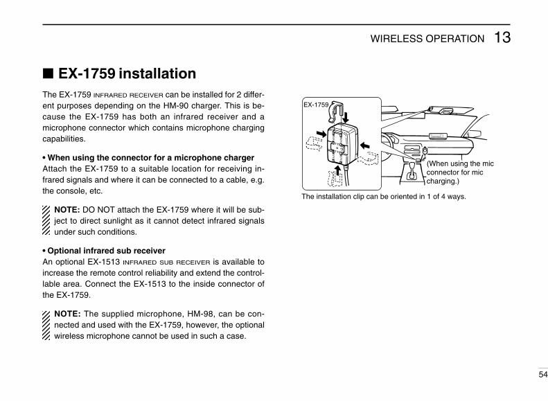
13WIRELESS OPERATION
54
EX-1759 installationThe EX-1759 INFRARED RECEIVER can be installed for 2 differ-ent purposes depending on the HM-90 charger. This is be-cause the EX-1759 has both an infrared receiver and amicrophone connector which contains microphone chargingcapabilities.
• When using the connector for a microphone chargerAttach the EX-1759 to a suitable location for receiving in-frared signals and where it can be connected to a cable, e.g.the console, etc.
NOTE: DO NOT attach the EX-1759 where it will be sub-ject to direct sunlight as it cannot detect infrared signalsunder such conditions.
• Optional infrared sub receiverAn optional EX-1513 INFRARED SUB RECEIVER is available toincrease the remote control reliability and extend the control-lable area. Connect the EX-1513 to the inside connector ofthe EX-1759.
NOTE: The supplied microphone, HM-98, can be con-nected and used with the EX-1759, however, the optionalwireless microphone cannot be used in such a case.
(When using the micconnector for miccharging.)
The installation clip can be oriented in 1 of 4 ways.
EX-1759

13 WIRELESS OPERATION
55
HM-90 switches
PTT SWITCH Push and hold to transmit; release to receive. Toggles between transmitting and receiving while the
one-touch PTT function is in use. BAND SWITCHES [BAND SELECT Y,Z]
Select a band. MONITOR SWITCH [MONI]
Toggles between opening and closing the squelch. SQUELCH LEVEL UP/DOWN SWITCHES
[YSQL], [ZSQL]Vary the squelch threshold point for noise mute.
BANDSELECT
MONI
REMOTE CONTROL MICROPHONE
VOLSQL
LOCK
JAPAN
AFC AFC-OFF PTT-M MW
PGR
CALL1 2 3 A
4 5 6 B
M 0 # D
MR VFO CLR
C-SQL DTMF D-OFF
SCAN
MONI
FUNC DTMFKEY
DTMFMEMO
MUTE SQL ENT
7 8 9 CDUP– DUP+ SIMP SPCH
PRIO REAR LOCK DEMO
TONE
HIGH MID LOW SET
T-SQLS T-SQL T-OFF ➓
Front and side panels Rear panel
FREQUENCY UP/DOWN SWITCHES [UP], [DN] Push either switch to change the operating frequency,
memory channel, set mode contents, etc. Push and hold either switch to start scanning.
ACTIVITY INDICATORLights red while a key is pushed; lights green while theone-touch PTT function is in use.
AUDIO VOLUME UP/DOWN SWITCHES[YVOL], [ZVOL]Adjust the accessed band’s audio level.
MODE INDICATORIndicates the microphone condition.• Lights red when [FUNC] is pushed.• Lights green when [DTMF KEY] is pushed.• Lights orange when [DTMF MEMO] is pushed.
LOCK SWITCH [LOCK]Locks all switches and keys on the microphone except forthe PTT switch.
➓ KEYPADUsed for controlling the transceiver, transmitting a DTMFmemory channel, etc.

13WIRELESS OPERATION
56
D Keypad
KEY FUNCTION SECONDARY FUNCTION (After )FUNC OTHER FUNCTIONS
Calls up a call channel. No secondary function.
• After :Input the appropriate digitfor frequency or memorychannel selection.
• After :Transmit the appropriateDTMF code.
• After :Transmit the appropriateDTMF memory contents.[0] to [9], [A] to [D] can beused for DTMF memory.
DTMFMEMO
DTMFKEY
DENT
DEMOSelects memory mode. No secondary function.
Selects VFO mode. Turns the one-touch PTT function ONand OFF.
Selects high output power. No secondary function.
Selects mid-high output power. No secondary function.
Selects low output power. Turns the DTMF memory function ON.
Selects – duplex. Turns the subaudible tone encoder ON.
Selects + duplex. Turns the pocket beep function ON.
Selects simplex. Turns the tone squelch function ON.
Mutes audio signals. Starts and stops a priority watch.
AFC
CALL1
AFC-OFF
2MR
PTT-M
3VFO
PGR
4HIGH
5
C-SQL
MID
6
DTMF
LOW
7DUP–
TONE
8DUP+
T-SQLS
9SIMP
T-SQL
0MUTE
PRIO

13 WIRELESS OPERATION
57
KEY FUNCTION SECONDARY FUNCTION (After )FUNC OTHER FUNCTIONS
Clears a digit before entry.
Cancels the scan, priority watch, orDTMF memory function.
Writes the VFO contents into the memorychannel or call channel.
Advances the memory channel numberwhen continuously pushed after program-ming is completed.
• After :Transmit the appropriateDTMF code.
[BMONI]Transmits a 1750 Hz tonecall signal for 0.5 sec.
[ASQL]Transmits a 1750 Hz tonecall signal while pushing.
DTMFKEY
Enters set mode and advances the setmode selection order.
Turns the DTMF memory function OFF.
Decreases the set mode selection orderafter entering set mode.
NOTE:The IC-207H has no voice synthesizerfunction.
Turns the subaudible tone encoder,pocket beep or tone squelch OFF.
Sets the keypad for numeral input. Enters and exits demonstration mode.
Toggles between opening and closingthe squelch.
Starts and stops scanning.
Selects 1 of the 4 preset squelch levels. Locks all the keys on the microphone key-pad.
MW
ACLR
B
D-OFF
SET
CSPCH
T-OFF
DENT
DEMO
M
SCAN
MONI
#SQL
REAR LOCK

13WIRELESS OPERATION
58
Microphoneaddress
The transceiver has 8 possible microphone addresses (in-cluding OFF) to help prevent interference from other HM-90WIRELESS MICROPHONES. Set both the microphone addressand microphone dip switch to the same value as follows.
NOTE: When the supplied microphone is connected, thetransceiver rejects control signals from the HM-90 evenwhen the microphone address is matched.
D Microphone address➀ Push [PWR] to turn power OFF.➁ While pushing [SET], turn power ON to enter initial set
mode.➂ Push [SET] a few times to
select the “Adr” display asshown at right.
➃ Rotate the tuning dial toset the microphone ad-dress to 0–7 or to turn the microphone control OFF.• When “Adr-oF” is selected, the transceiver rejects all control sig-
nals from the HM-90.
➄ Push [PWR] momentarily to exit initial set mode.
USING INITIAL SET MODE
The display shows the mi-crophone address is set to 2.
D Microphone dip switch➀ Remove the switch cover from the microphone rear panel.➁ Set the microphone dip switch and the microphone ad-
dress to the same value as shown below.➂ Replace the switch cover.
MICROPHONEADDRESS
DIP SWITCH
S1–1 S1–2 S1–3
Adr-0 OFF OFF OFF
Adr-1 (default) ON OFF OFF
Adr-2 OFF ON OFF
Adr-3 ON ON OFF
Adr-4 OFF OFF ON
Adr-5 ON OFF ON
Adr-6 OFF ON ON
Adr-7 ON ON ON
LOCK
AFC AFC-OFF PTT-M MW
PGR
CALL1 2 3 A
4 5 6 B
MR VFO CLR
C-SQL DTMF D-OFF
HIGH MID LOW SET
Dip switch
ON
OFF
1 2 3
(S1)Switch cover

OTHER FUNCTIONS14
59
Beep tones on/offYou can select silent operation by turning beep tones OFF oryou can select to have confirmation beeps sound at the pushof a switch by turning beep tones ON.
➀ Push [PWR] to turn power OFF.➁ While pushing [SET], turn power ON to enter initial set
mode.➂ Push [SET] one or more times until “bEP” appears.
• Pushing [MONI] reverses the order of selection.
➃ Rotate the tuning dial toselect the condition.• “bEP-oF”: Beep tones are
turned OFF.• “bEP-on”: Beep tones are
turned ON.
➄ Push [PWR] momentarily to exit initial set mode.
Time-out timerTo prevent accidental prolonged transmission with the one-touch PTT function, etc., the transceiver has a time-out timer.This timer cuts a transmission OFF after 3, 5, 15 or 30 min. ofcontinuous transmission. This timer can be cancelled (de-fault).
Approx. 10 sec. before the time-out timer passes, the trans-ceiver emits a beep tone as a warning.
➀ Push [PWR] to turn power OFF.➁ While pushing [SET], turn power ON to enter initial set
mode.➂ Push [SET] one or more times until “tot” appears.
• Pushing [MONI] reverses the order of selection.
➃ Rotate the tuning dial to select the desired time-out time orturn the timer OFF (“oF”).
➄ Push [PWR] momentarily to exit initial set mode.
USING INITIAL SET MODE USING INITIAL SET MODE
The display shows that the 5 min. timer is selected.
The display shows that the time-out timer is cancelled.
TOT
The display shows that the beep tones are turned ON.

14OTHER FUNCTIONS
60
Auto power-offThe auto power-off function conveniently turns the transceiverpower OFF after a preset time in which no operations are per-formed. In this way, when you forget to turn the power OFF,the transceiver automatically turns itself OFF, thereby con-serving battery power.
The time can be set to 30 min., 1 hr., 2 hrs. or turned OFF.The selected time is retained even when the transceiver isturned OFF via the auto power-off function. To cancel thefunction, select “oF” in step ➃ below.
➀ Push [PWR] to turn power OFF.➁ While pushing [SET], turn power ON to enter initial set
mode.➂ Push [SET] one or more times until “PoF” appears.
• Pushing [MONI] reverses the order of selection.
➃ Rotate the tuning dial toselect the desired autopower-off time or turn thetimer OFF (“oF”).• “AO” appears when an auto
power-off time is set.
➄ Push [PWR] momentarily to exit initial set mode.
Cooling fansetting
The transceiver has a heatsink and cooling fan to radiateheat. The cooling fan automatically turns ON while transmit-ting and remains ON for 2 min. after transmitting. The cool-ing fan can be activated continuously, if desired.
➀ Push [PWR] to turn power OFF.➁ While pushing [SET], turn power ON to enter initial set
mode.➂ Push [SET] one or more times until “FAn” appears.
• Pushing [MONI] reverses the order of selection.
➃ Rotate the tuning dial to set the cooling fan to automatic(“At”) or continuous (“on”).
➄ Push [PWR] momentarily to exit initial set mode.
USING INITIAL SET MODE USING INITIAL SET MODE
The display shows that the 30 min. timer is selected.
AO
The display shows that the cooling fan is set for automatic operation.
The display shows that the cooling fan is set for continuous operation.

14 OTHER FUNCTIONS
61
Microphone [F-1]/[F-2] keysSwitches on the transceiver’s front panel can be assigned tothe microphone’s [F-1] and [F-2] keys.
➀ Turn power OFF.➁ While pushing the desired switch on the transceiver and
[F-1] or [F-2] on the microphone, turn power ON.• The switches’ function is programmed into the key ([F-1] or [F-2]).
• Default settingThe following functions are assigned to the [F-1]/[F-2] keyswhen first applying power or after CPU resetting:
[F-1]: selects output power; push and hold to select duplexsetting
[F-2]: selects a tone function or none at all; push and hold tostart/stop tone scan
Display dimmerAdjust to suit lighting conditions and personal preference.
➀ Push and hold [SET] one or more times until “d-1”–“d4” ap-pears as follows.• Pushing [MONI] reverses the order of selection.
➁ Rotate the tuning dial toset the desired intensity.• Intensity can be set from “d1”
(dark) to “d4” (bright).
➂ Push [V/MHz] to return tonormal operation.
USING SET MODE
H I 195
The display shows the display backlighting set to brightest.

14OTHER FUNCTIONS
62
Squelch delayDuring operation, received signal strength often fluctuates.This can result in annoying repeated opening and closing ofthe squelch during reception of the same signal. The IC-207Hhas a built-in squelch delay function which helps prevent this.When both stations are operating from a fixed location, thisfunction should be set to “short” e.g. packet operation.
➀ Push [PWR] to turn power OFF.➁ While pushing [SET], turn power ON to enter initial set
mode.➂ Push [SET] one or more times until “Sqt” appears.
• Pushing [MONI] reverses the order of selection.
➃ Rotate the tuning dial toset the squelch delay to“L” (long) or “S” (short).
➄ Push [PWR] momentarilyto exit initial set mode.
USING INITIAL SET MODE
The display shows the squelch delay function is set to short.
Demonstration displayA demonstration function is available at power ON. This func-tion gives you a quick visual introduction to the function dis-play indicators.
➀ While pushing [BAND], push [PWR] to turn power ON.• The transceiver cycles through a visual tour of the function dis-
play indicators.
➁ Push any switch to exit demonstration mode and enter thenormal operating condition temporarily.
NOTE: The transceiver automatically returns to demon-stration mode after 2 min. in which no operations are per-formed. To deactivate the demonstration displaypermanently, turn power OFF, then while pushing [BAND],turn power ON again.

14 OTHER FUNCTIONS
63
Packet operation
D Data speedFor packet operation the transceiver can be set to one of twodata speeds: 1200 bps (default) or 9600 bps.
➀ Push [PWR] to turn power OFF.➁ While pushing [SET], turn power ON to enter initial set
mode.➂ Push [SET] one or more times until “bPS” appears.
• Pushing [MONI] reverses the order of selection.
➃ Rotate the tuning dial toselect the desired dataspeed.
➄ Push [PWR] momentarily to exit initial set mode.
USING INITIAL SET MODE
The display shows the data speed set to 1200 bps.
The display shows the data speed set to 9600 bps.
NOTE:For 1200 bps operation—• Disconnect the microphone plug from the microphone
connector during data transmission, otherwise the datasignal and voice signal are simultaneously transmitted.
For 9600 bps operation—• When the transceiver is set for 9600 bps data transmis-
sion in INTIAL SET MODE, the microphone signal is au-tomatically cut. Therefore, it is not necessary todisconnect the microphone plug from the connector inthis case.
• When pushing [PTT] during data transmission, datatransmission is interrupted and voice signals have prior-ity.

NOTE:• Read the instructions supplied with your TNC carefully
before attempting packet operation with the IC-207H.• Pin t AF OUT is for 1200 bps operation only. This pin
cannot be used for 9600 bps operation.• Over modulation may degrade signal quality. If you find
that many transmissions are failing, re-adjust the modu-lation level.
14OTHER FUNCTIONS
64
D 1200 bps packet operationq Connect the IC-207H and a TNC as illustrated below.
w Set the TNC for transmit.e Set transmit delay on the TNC to 30–50.r Adjust the TNC frequency deviation if necessary.
• When using a deviation meter:Adjust the output of the TNC so that frequency deviation is in therange ± 3 to 4 kHz.
• When NOT using a deviation meter:A receiver or transceiver is needed to monitor the transmission—compare the received audio output level when receiving a TNCmodulated signal with high level voice signals using the micro-phone. Then adjust the TNC modulated signal to a lower levelthan the voice modulated signal.
DATA IN
SQL
PTT
RX AUDIO
GND
TX AUDIO
TNC SIDE
GND
PTTP
SQ
AF OUT
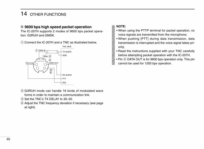
14 OTHER FUNCTIONS
65
NOTE:• When using the PTTP terminal for packet operation, no
voice signals are transmitted from the microphone.• When pushing [PTT] during data transmission, data
transmission is interrupted and the voice signal takes pri-ority.
• Read the instructions supplied with your TNC carefullybefore attempting packet operation with the IC-207H.
• Pin r DATA OUT is for 9600 bps operation only. This pincannot be used for 1200 bps operation.
D 9600 bps high speed packet operationThe IC-207H supports 2 modes of 9600 bps packet opera-tion: G3RUH and GMSK.
q Connect the IC-207H and a TNC as illustrated below.
w G3RUH mode can handle 16 kinds of modulated waveforms in order to maintain a communication link.
e Set the TNC’s TX DELAY to 30–50.r Adjust the TNC frequency deviation if necessary (see page
at right).
DATA IN
SQL
PTT
RX AUDIO
GND
TX AUDIO
TNC SIDE
GND
PTTP
SQ
DATA OUT

14OTHER FUNCTIONS
66
D Adjusting the transmit signal output fromthe TNC
When setting data transmission speed to 9600 bps, the DATA
signal coming from the TNC is applied exclusively to the in-ternal limiter circuitry to automatically maintain band width.
NEVER apply data levels from the TNC of over 0.6 Vp-p, oth-erwise the transceiver will not be able to maintain the bandwidth and may possibly interfere with other stations.
1. When using a level meter or synchroscope, adjust the TXaudio output level (DATA IN level) from the TNC as follows.0.4 Vp-p (0.2 Vrms): recommended level0.2 Vp-p–0.5 Vp-p (0.1 Vrms–0.25 Vrms): acceptable level
2. When NOT using a measuring device.q Connect the IC-207H to a TNC.w Enter a test mode (“CAL”, etc.) on the TNC, then transmit
some test data.e When the transceiver fails to transmit the test data or
transmits sporadically (TX indicator doesn’t appear orflashes):Decrease the TNC output level until the transmit indicatorlights continuously.When transmission is not successful even though the TXindicator lights continuously:Increase the TNC output level.

MAINTENANCE15
67
Troubleshooting If your transceiver seems to be malfunctioning, please checkthe following points before sending it to a service center.
PROBLEM POSSIBLE CAUSE SOLUTION REF.
No power comes on. • Power connector has a poor contact.• Polarity of the power connection is reversed.
• Blown fuse.
• Check the connector pins.• Reconnect the power cable observing the
proper polarity. Replace the fuse, if damaged.• Check the cause, then replace the fuse.
—pgs.13, 69p. 69
No sound comes from thespeaker.
• Volume level is too low.• The squelch level is set too tight.• A selective call or squelch function is activated
such as pocket beep or tone squelch.
• Rotate [VOL] clockwise.• Set the squelch level to the threshold.• Turn the appropriate function OFF.
p. 20p. 20pgs.50, 51
Sensitivity is low and onlystrong signals are audible.
• Antenna feedline or the antenna connector sol-der has a poor contact or is short circuited.
• Check, and if necessary, replace the feedline orsolder the antenna connector again.
p. 14
No contact possible with an-other station.
• The transceiver is set to semi-duplex.• The other station is using tone squelch.
• Set to simplex.• Turn ON the tone squelch function.
p. 24p. 51
Repeater cannot be ac-cessed.
• Wrong offset frequency is programmed.• Wrong subaudible tone frequency is pro-
grammed.
• Correct the offset frequency.• Correct the subaudible tone frequency.
p. 27p. 26
Frequency cannot be set. • The frequency lock function is activated.• Priority watch is paused on the watching fre-
quency.
• Turn the function OFF.• Push [(M/CALL)PRIO] to resume the watch.
p. 16p. 45
Frequency cannot be set via
the microphone.• The frequency lock function is activated.
• The microphone keypad lock function is acti-vated.
• Priority watch is paused on the watching fre-quency.
• Push and hold to deactivate the fre-quency lock function.
• Push [FUNC], then [A16KEY LOCK] to deacti-vate the microphone keypad lock function.
• Push [(M/CALL)PRIO] to resume the watch.
LOCK p. 16
p. 16
p. 45

15MAINTENANCE
68
PROBLEM POSSIBLE CAUSE SOLUTION REF.
Some memory channelscannot be selected via themicrophone keypad.
• The input channel number has not yet been pro-grammed.
• Rotate the tuning dial to check whether thechannel has been programmed or not.
p.29
Scan does not operate. • Squelch is open.• The selected scan edge memory channels (e.g.
1 A and 1b) have the same frequencies (for pro-grammed scan).
• Only 1 memory channel is programmed or otherchannels are set as skip channels.
• Priority watch is activated.
• Set the squelch to the threshold point.• Reset the scan edges.
• Program other memory channels or cancel thememory skip function in the desired channels.
• Turn the function OFF.
p. 20p. 40
pgs.30, 42p. 45
Transmission is automati-cally cut off.
• Time-out timer is activated. • Set the timer to OFF. p. 59
Transmission continueseven when the PTT is re-leased.
• One-touch PTT function is activated. • Turn the function OFF. p. 23
The function display showserroneous information.
• The CPU is malfunctioning. • Reset the CPU. p. 69

15 MAINTENANCE
69
Fuse replacementIf the fuse blows or the transceiver stops functioning, find thesource of the problem if possible, and replace the damagedfuse with a new, rated one (FGB 20 A) as shown in the dia-gram below.
Partial resettingIf you want to initialize the operating conditions without clear-ing the memory contents, etc., a partial reset function is avail-able for the transceiver.
While pushing [V/MHz], turn power ON to partially reset thetransceiver. Initialized settings: VFO frequency, SET mode settings. Retained settings: Memory channels, call channels, offset
freq. in memory/call, DTMF memory, ini-tial SET mode settings.
Resetting the CPUThe function display may occasionally display erroneous in-formation, (e.g. when first applying power). This may becaused externally by static electricity, or by other factors.
If this problem occurs, turn power OFF. After waiting a fewseconds, turn power ON again. If the problem persists, per-form the following procedure.
Partial resetting is alternatively available. See previous sec-tion for details.
➀ Push [PWR] to turn power OFF.➁ While pushing [SET] and [S.MW], turn power ON.
• “CLEAr” appears and the transceiver is reset.
CAUTION: Resetting the transceiver CLEARS allmemory information, and initializes all values in the trans-

SPECIFICATIONS 16
70
General• Frequency coverage
VERSION VHF UHF144–148 MHz
440–450 MHz
Asia144–148 MHz
430–440 MHz
Europe 144–146 MHz 430–440 MHz
Italy144–148 MHz 430–440 MHz
TxRx 136–174 MHz*1
TxRx 136–174 MHz*1 400–479 MHz*2
*1Guaranteed frequency coverage is 144–148 MHz.*2Guaranteed frequency coverage is 430–440 MHz.
• Mode : FM, AM*(*U.S.A. ver. only; 118–135.995 MHz)
• Antenna impedance : 50 Ω (SO-239)• Scanning speed : 16 ch/sec. (programmed scan)
8 ch/sec. (memory scan)• Power supply requirement : 13.8 V DC ± 15%• Usable temperature range : –10°C to +60°C; +14°F to +140°F• Dimensions : 140(W) × 40(H) × 184.5(D) mm
(projections not included) 51⁄2(W) × 19⁄16(H) × 71⁄4(D) in• Weight : 1.17 kg; 2.6 lb
Transmitter• Modulation system : Variable reactance frequency
modulation• Max. frequency deviation : ± 5.0 kHz• Spurious emissions : Less than –60 dB
• Microphone impedance : 600 Ω (8-pin modular)
• Output power and current drain:
Receiver• Receive system : Double conversion superheterodyne• Intermediate frequencies : 1st 46.05 MHz 2nd 450 kHz• Sensitivity (for 12 dB SINAD) : Less than 0.18 µV• Squelch sensitivity : Less than 0.13 µV (at threshold)
• Selectivity : More than 12 kHz/–6 dBLess than 30 kHz/–60 dB
• Spurious response : More than 60 dBrejection ratio
• Audio output power : More than 2.0 W at 10% distortionwith the 8 Ω internal speaker
• Current drain :Max rated audio 1.0 AStandby 0.8 A
CONDITION POWER
144 MHz
50 W20 W10 W
430(440) MHz
12.0 A6.5 A5.5 A
11.0 A35 W20 W 6.5 A10 W 5.5 A
High
Mid-LowMid-High
HighMid-HighMid-Low
All stated specifications are subject to change without notice orobligation.
CURRENT
U.S.A.118–174 MHz*1Rx
Tx
5 W 4.5 ALow
5 W 4.5 ALow

OPTIONS17
71
Some of the following options may not be available due tovariations in local electrical standards, etc. If you have anyquestions regarding options please consult your Icom Dealer.
D SpeakersSP-7 EXTERNAL SPEAKERFor base station use. Cable length: 1.0 m; 3.3 ft
SP-10 EXTERNAL SPEAKERCompact design. Cable length: 1.5 m; 4.9 ft
SP-12 EXTERNAL SPEAKERSlim-type. Cable length: 2.0 m; 6.6 ft
D Separation accessoriesOPC-600/601 SEPARATION CABLEFor operation with the front panel detached.Cable lengthOPC-600: 3.5 m; 11.5 ft OPC-601: 7.0 m; 23.0 ftMB-58 REMOTE CONTROLLER BRACKETMounts the remote controller in a convenient location for op-eration with the front panel detached from the main body.MB-65 REMOTE CONTROLLER BRACKETMounts the remote controller with MB-58. Adjustable angleand direction for optimum installation positioning.OPC-440/647 MIC EXTENSION CABLECable lengthOPC-440: 5.0 m; 16.4 ft OPC-647: 2.5 m; 8.2 ft.OPC-347 DC POWER CABLEHas a 20 A capacity and a length of 7.0 m (23.0 ft).OPC-441 SPEAKER EXTENSION CABLECable length: 5.0 m; 16.4 ft.
SP-7 SP-10 SP-12 MB-65
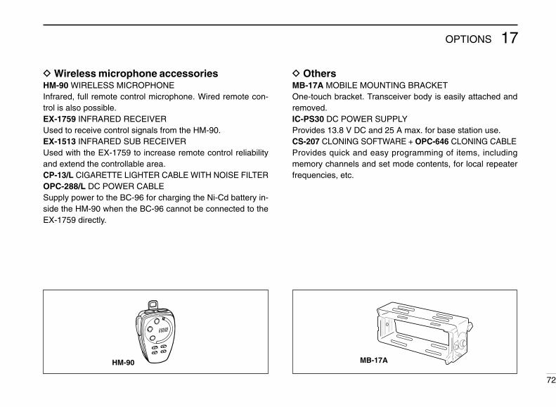
17OPTIONS
72
D Wireless microphone accessoriesHM-90 WIRELESS MICROPHONEInfrared, full remote control microphone. Wired remote con-trol is also possible.EX-1759 INFRARED RECEIVERUsed to receive control signals from the HM-90.EX-1513 INFRARED SUB RECEIVERUsed with the EX-1759 to increase remote control reliabilityand extend the controllable area.CP-13/L CIGARETTE LIGHTER CABLE WITH NOISE FILTEROPC-288/L DC POWER CABLESupply power to the BC-96 for charging the Ni-Cd battery in-side the HM-90 when the BC-96 cannot be connected to theEX-1759 directly.
D OthersMB-17A MOBILE MOUNTING BRACKETOne-touch bracket. Transceiver body is easily attached andremoved.IC-PS30 DC POWER SUPPLYProvides 13.8 V DC and 25 A max. for base station use.CS-207 CLONING SOFTWARE + OPC-646 CLONING CABLEProvides quick and easy programming of items, includingmemory channels and set mode contents, for local repeaterfrequencies, etc.
HM-90 MB-17A

MODE ARRANGEMENT18
73
MEMORY MODE (p.29)
VFO MODE (p. 15)
CALL CHANNELS (p. 34)
SCRATCH PADMEMORY (p. 36)
DTMFDUP LOCKSETMONILOW
PRIO T SCANM ⁄ CALL TONE
SCANV⁄ MHz
H I 195
See p. 46 for details.
DTMF MEMORY
or no operation for 30 sec.
Whe
n th
e D
TM
F
mem
ory
enco
der
is
activ
ated
.
DTMFDUP LOCKSETMONILOW
PRIO T SCANM ⁄ CALL TONE
SCANV⁄ MHz
H I 195
DTMFDUP LOCKSETMONILOW
PRIO T SCANM ⁄ CALL TONE
SCANV⁄ MHz
H I 195
DTMFDUP LOCKSETMONILOW
PRIO T SCANM ⁄ CALL TONE
SCANV⁄ MHz
H I 195
DTMFDUP LOCKSETMONILOW
PRIO T SCANM ⁄ CALL TONE
SCANV⁄ MHz
H IM
195
DTMFDUP LOCKSETMONILOW
PRIO T SCANM ⁄ CALL TONE
SCANV⁄ MHz
H I 195
[V/MHz] [V/MHz][M/CALL]
[M/CALL]
BAND
[SET]
[V/MHz]
Although the following chart refers mainly to the VHF band, the transceiver has the samemode arrangement in the UHF band.

18MODE ARRANGEMENT
74
INITIAL SET MODESET MODE
Scan resumecondition (p. 43)
Skip channel*2
setting (p. 42)
Beep tone on/off(p. 59)
Turn power ON while pushing [SET].
Time-out timer(p. 59)
Auto power-off(p. 60)
Auto repeater*(p.28)
* U.S.A. version only.
Cooling fansetting (p. 60)
Dataspeed (p. 63)
Squelchdelay (p. 62)
Microphoneaddress (p. 58)
DTMF speed(p. 49)
Subaudible tonefrequency (p. 26)
Tuning step*1
(p. 18)
Offset frequency(p. 27)
Repeater tonefrequency (p. 26)
H I 195
T
Display backlighting(p. 61)H I 1
95
H I 195
DUPH I 1
95
*1Only appears when entering SET mode from VFO mode.*2Only appears when entering SET mode from memory mode.
H IM
SKIP
195
H I 195
TSQLH I 1
95
[SET] [SET][MONI] [MONI]

6-9-16 Kamihigashi, Hirano-ku, Osaka 547 Japan
A-5417D-1EX-qPrinted in JapanCopyright © 1996 by Icom Inc.
Count on us!