
INSTRUCTION MANUAL PULSAR Universal Test · PDF fileDirect Current Alternating Current Both...
188
Part Number 14850 Rev. 10, Date 11/11/99 5 INSTRUCTION MANUAL For 5 PULSAR ® Universal Test System The PULSAR test set includes a ROM-resident computer program. This program belongs to AVO Multi-Amp Corporation and contains trade secret ideas and information of AVO Multi- Amp Corporation. To the extent this program contains ideas, AVO Multi-Amp Corporation intends to protect and enforce its rights under state law. To the extent the program is deemed to constitute a form of expression of idea, AVO Multi-Amp Corporation intends to protect and enforce its rights under the Copyright Act of 1976. The Statutory Copyright notice has been affixed hereto in the event that it is later determined that the program has been published within the meaning of the Copyright Act of 1976. It is essential that this instruction book be read thoroughly before putting the equipment in service. www . ElectricalPartManuals . com
Transcript of INSTRUCTION MANUAL PULSAR Universal Test · PDF fileDirect Current Alternating Current Both...
Part Number 14850 Rev. 10, Date 11/11/99
5
INSTRUCTION MANUAL For 5 PULSAR® Universal Test System The PULSAR test set includes a ROM-resident computer program. This program belongs to AVO Multi-Amp Corporation and contains trade secret ideas and information of AVO Multi-Amp Corporation. To the extent this program contains ideas, AVO Multi-Amp Corporation intends to protect and enforce its rights under state law. To the extent the program is deemed to constitute a form of expression of idea, AVO Multi-Amp Corporation intends to protect and enforce its rights under the Copyright Act of 1976. The Statutory Copyright notice has been affixed hereto in the event that it is later determined that the program has been published within the meaning of the Copyright Act of 1976.
It is essential that this instruction book be read thoroughly before putting the equipment in service.
www . El
ectric
alPar
tMan
uals
. com

REVISION HISTORY
Revision ECN # Date 1 00000 09/28/93 2 25566 10/07/93 3 25614 10/29/93 4 25858 03/30/94 5 25969 06/28/94 6 26039 08/16/94 7 26062 09/06/94 8 26920 06/24/96 9 28156 08/26/98 10 28688 11/11/99
APPRECIATION We are indebted to the manufacturers of protective relays, who have given their time and advice in the preparation of this instruction book. And, we also express our gratitude to engineers and technicians all over the country for their counsel and suggestions towards the testing and maintenance of protective relays. IMPORTANT The information and data contained within this instruction manual are proprietary with AVO MULTI-AMP Corporation. The equipment described herein may be protected by one or more U.S. letters patent. AVO MULTI-AMP specifically reserves to itself all rights to such proprietary information as well as all rights under any such patent, none of which is waived by the submission of this instruction manual to anyone. The recipient, if a Government agency, acknowledges that this instruction book and the equipment described were procured with "Limited Rights" to technical data as described in ASPR 9-203 (b). Copyright AVO MULTI-AMP Corporation, 1992, 1993, 1994, 1996, 1998
www . El
ectric
alPar
tMan
uals
. com
SAFETY PRECAUTIONS
WARNING: VOLTAGES GENERATED BY THIS INSTRUMENT CAN BE HAZARDOUS
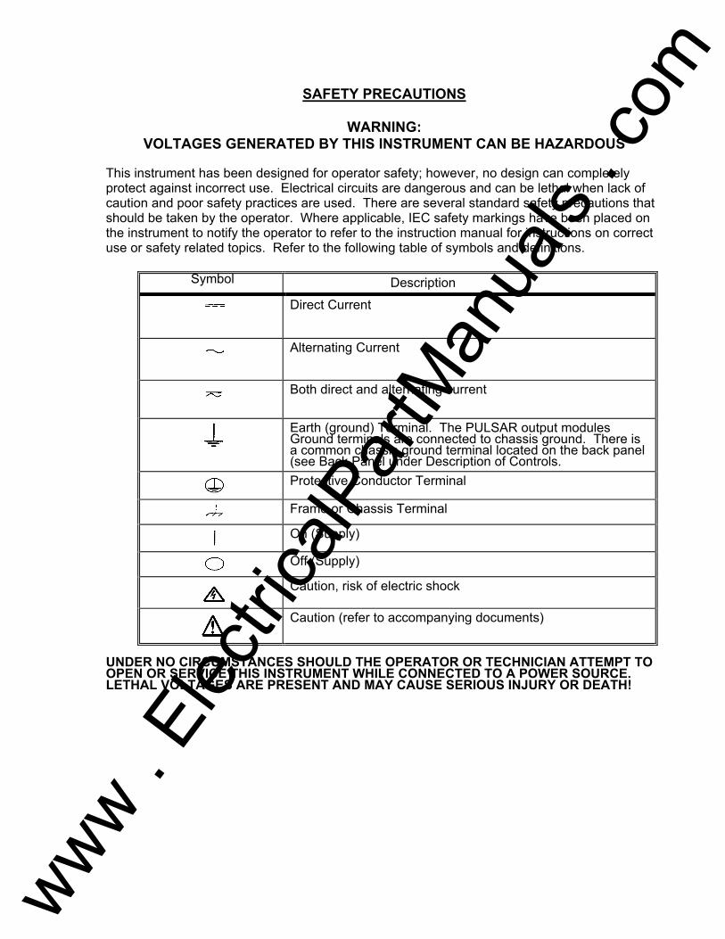
This instrument has been designed for operator safety; however, no design can completely protect against incorrect use. Electrical circuits are dangerous and can be lethal when lack of caution and poor safety practices are used. There are several standard safety precautions that should be taken by the operator. Where applicable, IEC safety markings have been placed on the instrument to notify the operator to refer to the instruction manual for instructions on correct use or safety related topics. Refer to the following table of symbols and definitions.
Symbol Description
Direct Current
Alternating Current
Both direct and alternating current
Earth (ground) Terminal. The PULSAR output modules Ground terminals are connected to chassis ground. There is a common chassis ground terminal located on the back panel (see Back Panel under Description of Controls.
Protective Conductor Terminal
Frame or Chassis Terminal
On (Supply)
Off (Supply)
Caution, risk of electric shock
Caution (refer to accompanying documents)
UNDER NO CIRCUMSTANCES SHOULD THE OPERATOR OR TECHNICIAN ATTEMPT TO OPEN OR SERVICE THIS INSTRUMENT WHILE CONNECTED TO A POWER SOURCE. LETHAL VOLTAGES ARE PRESENT AND MAY CAUSE SERIOUS INJURY OR DEATH!
www . El
ectric
alPar
tMan
uals
. com
SAFETY PRECAUTIONS CONTINUED
The following are some specific safety related items associated with the PULSAR test system.
Always start with the power OFF, before connecting the power cord. Make sure outputs are off before attempting to make test connections. Always use properly insulated test leads. The test leads supplied with the unit are rated for the continuous output ratings of the test system, and should be properly used and cared for. Do not use cracked or broken test leads. Be careful when using the DC Battery Simulator. The DC is on continuously when the power to the test system is on. Make test connections to the device under test prior to connecting the DC Battery Simulator. Always turn the test system off before disconnecting the power cord or removing / inserting output modules. If removing or inserting modules (output modules, timer modules, etc.) turn unit off, wait several minutes and disconnect the power cord from the test system before removing any module. This allows internal power supply charging voltages to dissipate. DO NOT power up without module mounting screws and rear thumb screws secured.
UNDER NO CIRCUMSTANCES SHOULD THE OPERATOR PUT HIS HANDS OR TOOLS INSIDE THE TEST SYSTEM CHASSIS, OR BACK PLANE AREA, WITH THE TEST SYSTEM CONNECTED TO A POWER SOURCE AND TURNED ON. LETHAL VOLTAGES ARE PRESENT AND MAY CAUSE SERIOUS INJURY OR DEATH!
www . El
ectric
alPar
tMan
uals
. com
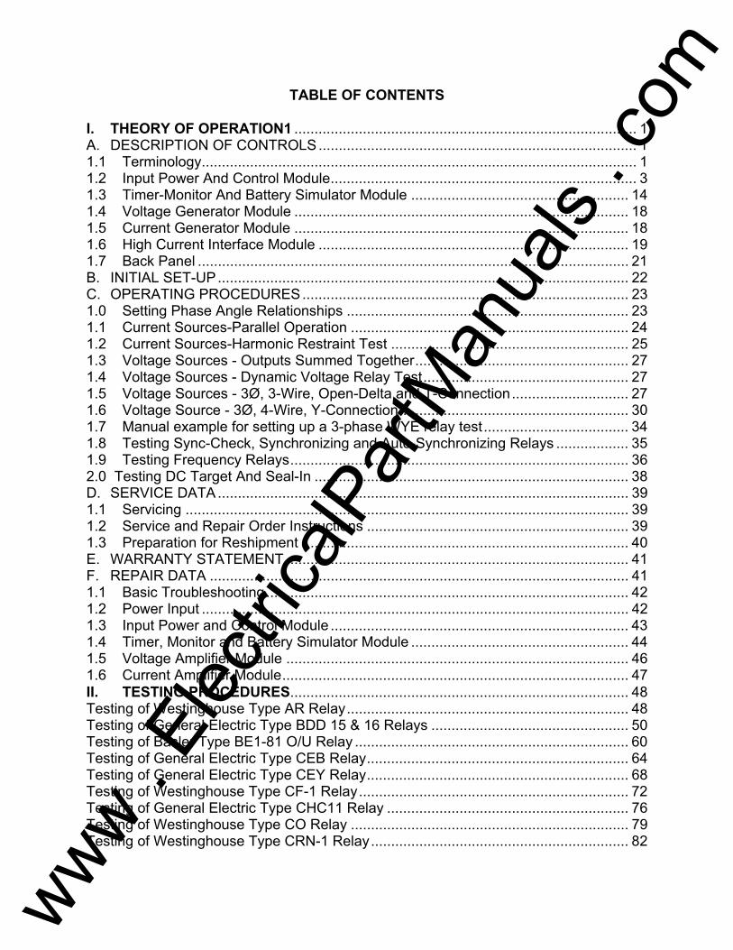
TABLE OF CONTENTS I. THEORY OF OPERATION1 ..................................................................................... 1 A. DESCRIPTION OF CONTROLS ............................................................................... 1 1.1 Terminology ............................................................................................................ 1 1.2 Input Power And Control Module ............................................................................ 3 1.3 Timer-Monitor And Battery Simulator Module ...................................................... 14 1.4 Voltage Generator Module ................................................................................... 18 1.5 Current Generator Module ................................................................................... 18 1.6 High Current Interface Module ............................................................................. 19 1.7 Back Panel ........................................................................................................... 21 B. INITIAL SET-UP ...................................................................................................... 22 C. OPERATING PROCEDURES ................................................................................. 23 1.0 Setting Phase Angle Relationships ...................................................................... 23 1.1 Current Sources-Parallel Operation ..................................................................... 24 1.2 Current Sources-Harmonic Restraint Test ........................................................... 25 1.3 Voltage Sources - Outputs Summed Together ..................................................... 27 1.4 Voltage Sources - Dynamic Voltage Relay Test ................................................... 27 1.5 Voltage Sources - 3Ø, 3-Wire, Open-Delta and T-Connection ............................. 27 1.6 Voltage Source - 3Ø, 4-Wire, Y-Connection ......................................................... 30 1.7 Manual example for setting up a 3-phase WYE relay test .................................... 34 1.8 Testing Sync-Check, Synchronizing and Auto-Synchronizing Relays .................. 35 1.9 Testing Frequency Relays .................................................................................... 36 2.0 Testing DC Target And Seal-In .............................................................................. 38 D. SERVICE DATA ...................................................................................................... 39 1.1 Servicing .............................................................................................................. 39 1.2 Service and Repair Order Instructions ................................................................. 39 1.3 Preparation for Reshipment ................................................................................. 40 E. WARRANTY STATEMENT ..................................................................................... 41 F. REPAIR DATA ........................................................................................................ 41 1.1 Basic Troubleshooting .......................................................................................... 42 1.2 Power Input .......................................................................................................... 42 1.3 Input Power and Control Module .......................................................................... 43 1.4 Timer, Monitor and Battery Simulator Module ...................................................... 44 1.5 Voltage Amplifier Module ..................................................................................... 46 1.6 Current Amplifier Module ...................................................................................... 47 II. TESTING PROCEDURES .................................................................................... 48 Testing of Westinghouse Type AR Relay ...................................................................... 48 Testing of General Electric Type BDD 15 & 16 Relays ................................................. 50 Testing of Basler Type BE1-81 O/U Relay .................................................................... 60 Testing of General Electric Type CEB Relay ................................................................. 64 Testing of General Electric Type CEY Relay ................................................................. 68 Testing of Westinghouse Type CF-1 Relay ................................................................... 72 Testing of General Electric Type CHC11 Relay ............................................................ 76 Testing of Westinghouse Type CO Relay ..................................................................... 79 Testing of Westinghouse Type CRN-1 Relay ................................................................ 82
www . El
ectric
alPar
tMan
uals
. com
TABLE OF CONTENTS Continued
ii
Testing of Westinghouse Type CV Relay ...................................................................... 86 Testing of Westinghouse Type CVE Relay ................................................................... 88 Testing of General Eelectric Type GCX Relay .............................................................. 92 Testing of General Electric Type GCY Relay ................................................................ 98 Testing of General Electric Type GGP Relay .............................................................. 102 Testing of Westinghouse Type HU and HU-1 Relays .................................................. 106 Testing of General Electric Type IAC Relays .............................................................. 118 Testing of General Electric Type IAV Relay ................................................................ 122 Testing of General Electric Type IJF Relay ................................................................. 125 Testing of General Electric Type IJS Relay ................................................................. 128 Testing of Westinghouse Type IRDand IRV Relays .................................................... 132 Testing of General Electric Type JBC and JBCV Relays ............................................ 136 Testing of General Electric Type JBCG51 Relay ........................................................ 140 Testing of Westinghouse Type KA Relay .................................................................... 143 Testing of Westinghouse Type KC Relay .................................................................... 146 Testing of Westinghouse Type KD Relay .................................................................... 149 Testing of General Electric type IFCV Relay ............................................................... 156 Testing of Westinghouse Type KLF Relay .................................................................. 160 Testing of General Electric Type PJC Relay ............................................................... 165 Testing of General Electric Type PJV Relay ............................................................... 169 Testing of BaslerType PRS-170 Relay ........................................................................ 173 Testing of General Electric Type PVD Relay ............................................................... 178 III. APPENDIX A: Remote Operation Command Set IV. APPENDIX B: PULSAR Error Codes V. APPENDIX C: PULSAR Product Specifications
www . El
ectric
alPar
tMan
uals
. com
1
I. THEORY OF OPERATION A. DESCRIPTION OF CONTROLS This section of the instruction manual describes the function of all the various
controls, switches, push-buttons or keys, alpha-numeric keys, binding posts etc., which are located on the front panel of the AVO Multi-Amp's PULSAR® Universal Test System. All controls and outputs are clearly marked and logically grouped so that continual reference to the instruction manual should not be necessary after the operator has become acquainted with the operation of the test system.
Since the PULSAR design is based on a "modular" concept, the front panel of a
PULSAR may vary from unit to unit depending on the modules selected. There are many unique modules or sections a PULSAR may have; Input Power and Control Module, Timer/Monitor and Battery Simulator Module, Voltage Generator Module, Current Generator Module, High Current Interface Module and Blank Module.
Every PULSAR must have the Input Power and Control Module. For testing
a relay or for monitoring the response of a device, the Timer/Monitor and Battery Simulator Module is (mandatory) a must. There may be one or more Voltage or Current Modules as required.
1.1 Terminology There are a few terms and definitions that will be used throughout this manual. A
brief description follows. 1.1.1 Procedure A sequence of front panel key depressions pertaining to the execution of a
specific function will be collectively called a procedure. 1.1.2 Procedure Diagram A procedure diagram is a diagram that is used to explain the correct sequence
and content for entering front panel keys for a single function to the PULSAR unit. Such diagrams contain boxes, lines, text, and sometimes arrows.
Horizontal lines without an arrow pointing left that connect boxes (or that connect
other lines which eventually connect boxes) indicate logic flow from left to right. Presence of an arrow pointing left indicates logic flow opposite to the default direction.
If a vertical line connects to a line with a left arrow, that vertical line indicates a
permissible logic choice only in the direction of that arrow. Other vertical lines that have multiple choices toward the right indicate that each of the choices to the right is logically permissible.
www . El
ectric
alPar
tMan
uals
. com
2
1.1.3 Button Or Key Constants The contents of certain boxes within procedure diagrams are key constants. A
key constant is a set of capital letters and represents a front panel key (except up and down arrow keys, digits, the colon, and the decimal point).
1.1.4 Procedure Variables A procedure variable is a set of lower case letters that occurs within a box in a
procedure diagram. The form and function of each procedure variable is defined in each procedure.
1.1.5 Terminator A terminator is a final box in a procedure diagram for the front panel of the
PULSAR unit. The two valid terminators are the key constant EX (the execute key) and the empty box.
The empty box indicates that the user intends to enter another procedure (function) following this one, and that the user wants this procedure to be executed at virtually the same time as the next procedure. Procedures ending with an empty box are stored until a procedure ending with EXECUTE is received. This allows the cancellation of the effect of a human entry time delay between each pair of procedures in a lengthy string of procedures. All procedures between EXECUTE key depressions will be executed nearly simultaneously. The empty box is merely a convenience in a procedure diagram; it does not correspond to any key depression. EXECUTE A procedure (or string of procedures separated by empty boxes) which ends with an EXECUTE terminator will be executed as soon as it can be processed. 1.1.6 Multiple Choice Symbol The vertical symbol below is the multiple choice beginning symbol. This shows the starting point for a procedure diagram which has more than one choice for a starting procedure constant.
www . El
ectric
alPar
tMan
uals
. com
3
1.1.7 Shift Key The numeric keypad area contains two possible functions for each key. The digit usage of these keys is accomplished in a normal fashion. The other (miscellaneous) usage requires, that prior to depressing the target key at its lettered description, one must first depress the Shift key. This Shift key must be released prior to depressing the target key. The Shift key's effect only lasts for the next one keystroke. If that next keystroke is not a key in the numeric keypad area, the prior depression of the Shift key is ignored.
1.2 Input Power And Control Module This module will always be located at the top-left corner of the unit. As mentioned earlier this module is vital to PULSAR operation. This module may be divided into two sections: Power On section (left half) which is devoted to the power on and reset operation of the unit; and the Control section (right half) which allows manual selection of voltage and/or current generator, selection and setting of AC/DC parameters, selection of phase, frequency and range, timer start/stop controls, selection of SYNC parameters, selection of waveforms, outputs on/off etc. A description of each available switch and its operation is described below: POWER ON/OFF Switch Vertically located in the Power On section of the module, labeled 1/0, this switch energizes a PULSAR unit ("1" = ON and "0" = OFF). RESET Switch Located right below the POWER ON/OFF switch, resets the unit to its power-up state without having to power down the entire unit. Use a pencil or a pen to reach and execute. A typical situation when a RESET operation may be required is when there is a "communication lock-up" between a Personal Computer and PULSAR.
www . El
ectric
alPar
tMan
uals
. com

4
CONTROL SECTION The right half of the module is called the Control section. It can be divided into five individual menus which offer the following features:
SELECT/GENERATOR:
<< VOLTAGE << EXECUTE GENERATOR generator # or CURRENT channel # GENERATOR
where,
VOLTAGE - denotes the VOLTAGE key and indicates that a voltage
generator is being selected.
CURRENT - denotes the CURRENT key and indicates that a current generator is being selected.
generator # or channel # - a single digit in the range of 0 to 9 indicating the generator to
be included in this selection. 0 (zero) is pre-defined to mean all generators of the same
type e.g., V, 0 selects all voltage generators. NOTE: In this example and in the subsequent examples
comma (',') is a separator. It is neither a command nor a part of the command sequence.
Example: VOLTAGE, 0, EXECUTE. This sequence of key
strokes would select all available voltage generators. Located at the top of the Control section, this menu incorporates two keys labeled VOLTAGE and CURRENT which, along with the key labeled EXECUTE (located at the bottom of the Control section under the "OUTPUTS" menu), select a group of voltage and/or current generators which will be acted upon by other options on the Control section. This selection remains effective until the next selection is made or until a unit RESET is executed. All voltage generators may be freely interchanged among the slots of PULSAR unit without manually adjusting anything in these generators. The same is true
www . El
ectric
alPar
tMan
uals
. com
5
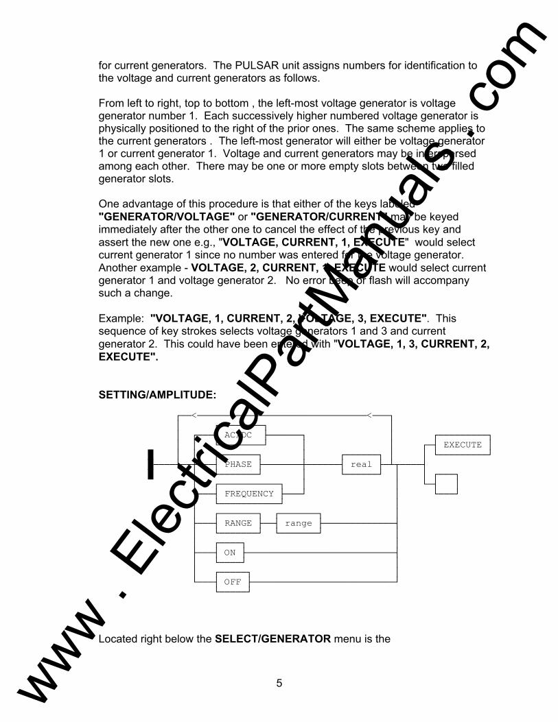
for current generators. The PULSAR unit assigns numbers for identification to the voltage and current generators as follows. From left to right, top to bottom , the left-most voltage generator is voltage generator number 1. Each successively higher numbered voltage generator is physically positioned to the right of the prior ones. The same scheme applies to the current generators . The left-most generator will either be voltage generator 1 or current generator 1. Voltage and current generators may be interspersed among each other. There may be one or more empty slots between two filled generator slots. One advantage of this procedure is that either of the keys labeled "GENERATOR/VOLTAGE" or "GENERATOR/CURRENT" may be keyed immediately after the other one to cancel the effect of the previous key and assert the new one e.g., "VOLTAGE, CURRENT, 1, EXECUTE" would select current generator 1 since no number was entered for the voltage generator. Another example - VOLTAGE, 2, CURRENT, 1, EXECUTE would select current generator 1 and voltage generator 2. No error beep or flash will accompany such a change.
Example: "VOLTAGE, 1, CURRENT, 2, VOLTAGE, 3, EXECUTE". This sequence of key strokes selects voltage generators 1 and 3 and current generator 2. This could have been entered with "VOLTAGE, 1, 3, CURRENT, 2, EXECUTE".
SETTING/AMPLITUDE: << AC/DC EXECUTE PHASE real FREQUENCY RANGE range ON OFF
Located right below the SELECT/GENERATOR menu is the
www . El
ectric
alPar
tMan
uals
. com

6
SETTING/AMPLITUDE menu. This menu has six keys labeled AC, DC, PHASE, FREQ, RANGE and TIMER START. These keys offer the following features. AC Selects AC output for selected voltage and/or current generators.
DC Selects DC output for selected voltage and/or current generators.
PHASE Denotes the PHASE key and sets the phase angle (in degrees) of
the selected voltage and/or current generators' AC output. PULSAR unit will display the input real number in the range of 0 to 359.9 degrees only. Any angle greater than 359.9 degrees simply wraps around. For example, entering an angle of 600 degree displays 240.
FREQ Denotes the FREQUENCY key and sets the frequency of the
selected generator(s) in Hertz. However, when the frequency is changed, it will be out of phase until all the generators are shut off or until the Restore Phase procedure is executed (more later on RST PH). To indicate this condition the generator whose frequency is changed will show dashes at its phase display.
RANGE Denotes the RANGE key and sets the range for the selected
voltage and/or current generators. The range option is only allowable when the relevant generator is off; otherwise it is a generator range error.
NOTE: The generator range number, which may be zero
(automatic ranging) or the maximum number desired in volts or amps, not to exceed 300 in volts or 30 in amps. The PULSAR unit will choose the lowest range which contains the desired value. For example, if 150 volts is selected for a voltage generator, the 300 volt range will be selected. The following ranges are available:
0 - automatic ranging. 300 - Voltage generator: 300 volts. 30 - Voltage generator: 30 volts. 30 - Current generator: 30 amps. 15 - Current generator: 15 amps. 3 - Current generator: 3 amps.
www . El
ectric
alPar
tMan
uals
. com
7
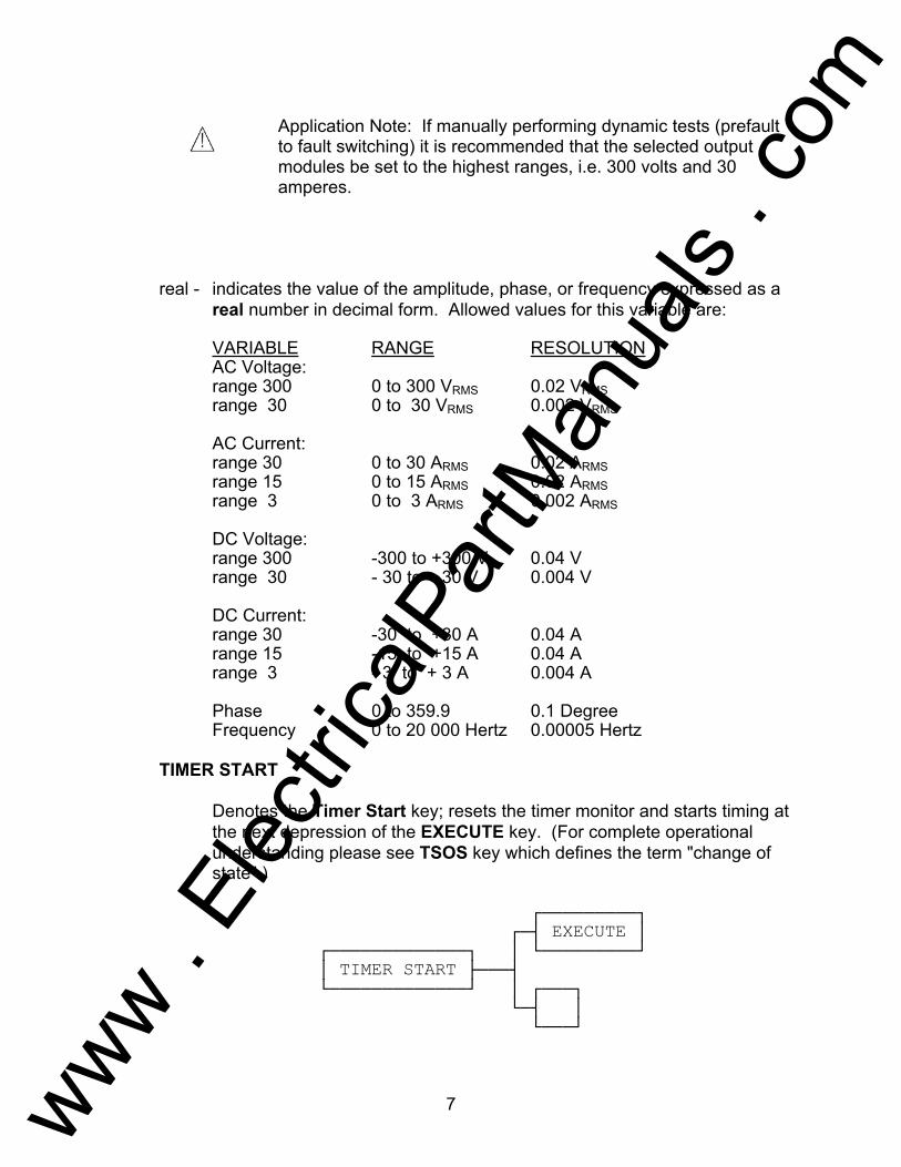
Application Note: If manually performing dynamic tests (prefault to fault switching) it is recommended that the selected output modules be set to the highest ranges, i.e. 300 volts and 30 amperes.
real - indicates the value of the amplitude, phase, or frequency expressed as a real number in decimal form. Allowed values for this variable are:
VARIABLE RANGE RESOLUTION AC Voltage: range 300 0 to 300 VRMS 0.02 VRMS range 30 0 to 30 VRMS 0.002 VRMS AC Current: range 30 0 to 30 ARMS 0.02 ARMS range 15 0 to 15 ARMS 0.02 ARMS range 3 0 to 3 ARMS 0.002 ARMS DC Voltage: range 300 -300 to +300 V 0.04 V range 30 - 30 to + 30 V 0.004 V DC Current: range 30 -30 to +30 A 0.04 A range 15 -15 to +15 A 0.04 A range 3 - 3 to + 3 A 0.004 A Phase 0 to 359.9 0.1 Degree Frequency 0 to 20 000 Hertz 0.00005 Hertz TIMER START
Denotes the Timer Start key; resets the timer monitor and starts timing at the next depression of the EXECUTE key. (For complete operational understanding please see TSOS key which defines the term "change of state".)
EXECUTE TIMER START
www . El
ectric
alPar
tMan
uals
. com
8
The timer will stop when the timer stop-gate changes state unless the TSOS function is active. The timer monitor may also be started with a change of state of the start binding posts.
Example: TIMER START, EXECUTE. Starts the timer immediately.
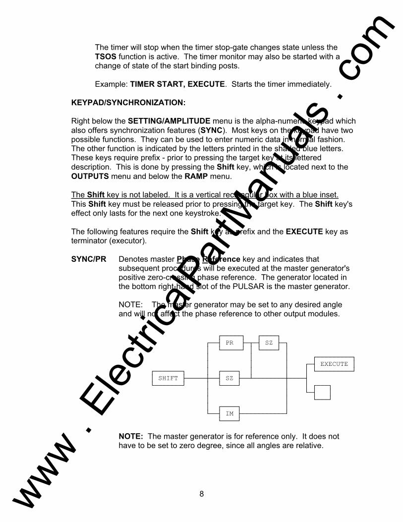
KEYPAD/SYNCHRONIZATION: Right below the SETTING/AMPLITUDE menu is the alpha-numeric keypad which also offers synchronization features (SYNC). Most keys on the keypad have two possible functions. They can be used to enter numeric data in normal fashion. The other function is indicated by the letters printed in the shaded blue letters. These keys require prefix - prior to pressing the target key at its lettered description. This is done by pressing the Shift key, which is located next to the OUTPUTS menu and below the RAMP menu. The Shift key is not labeled. It is a vertical rectangular box with a blue inset. This Shift key must be released prior to pressing the target key. The Shift key's effect only lasts for the next one keystroke. The following features require the Shift key as prefix and the EXECUTE key as terminator (executor). SYNC/PR Denotes master Phase Reference key and indicates that
subsequent procedures will be executed at the master generator's positive zero-crossing phase reference. The generator located in the bottom right-hand slot of the PULSAR is the master generator.
NOTE: The master generator may be set to any desired angle
and will not affect the phase reference to other output modules. PR SZ EXECUTE SHIFT SZ IM NOTE: The master generator is for reference only. It does not
have to be set to zero degree, since all angles are relative.
www . El
ectric
alPar
tMan
uals
. com
9
SYNC/SZ Denotes the SZ (Self Zero) key and indicates that subsequent procedures will be executed synchronous with each generator's own positive going zero crossing (self zero crossing).
SYNC/IM Denotes the IM (Immediate) key and indicates that subsequent
procedures will be executed immediately (point on waveform). PRSZ Denotes the PRSZ (zero crossing after master phase reference)
keys and indicates that subsequent procedures will be executed at the first zero crossing after the master generator phase reference. NOTE: PRSZ is the combination of the keys PR and SZ which must be pressed sequentially for proper operation.
Example: Shift, PR, EXECUTE - execute procedures at the master
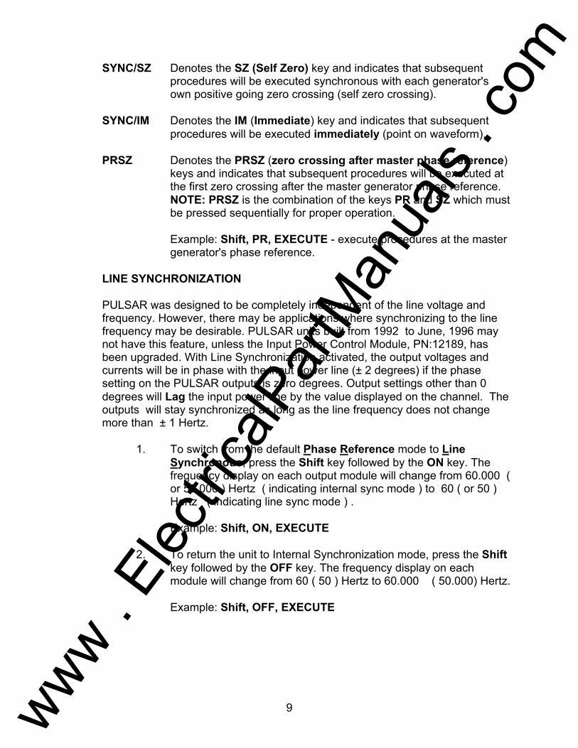
generator's phase reference. LINE SYNCHRONIZATION PULSAR was designed to be completely independent of the line voltage and frequency. However, there may be applications where synchronizing to the line frequency may be desirable. PULSAR units built from 1992 to June, 1996 may not have this feature, unless the Input Power Control Module, PN:12189, has been upgraded. With Line Synchronization activated, the output voltages and currents will be in phase with the input power line (± 2 degrees) if the phase setting on the PULSAR outputs is zero degrees. Output settings other than 0 degrees will Lag the input power line by the value displayed on the channel. The outputs will stay synchronized as long as the line frequency does not change more than ± 1 Hertz. 1. To switch from the default Phase Reference mode to Line
Synchronous, press the Shift key followed by the ON key. The frequency display on each output module will change from 60.000 ( or 50.000 ) Hertz ( indicating internal sync mode ) to 60 ( or 50 ) Hertz ( indicating line sync mode ) .
Example: Shift, ON, EXECUTE
2. To return the unit to Internal Synchronization mode, press the Shift key followed by the OFF key. The frequency display on each module will change from 60 ( 50 ) Hertz to 60.000 ( 50.000) Hertz.
Example: Shift, OFF, EXECUTE
www . El
ectric
alPar
tMan
uals
. com
10
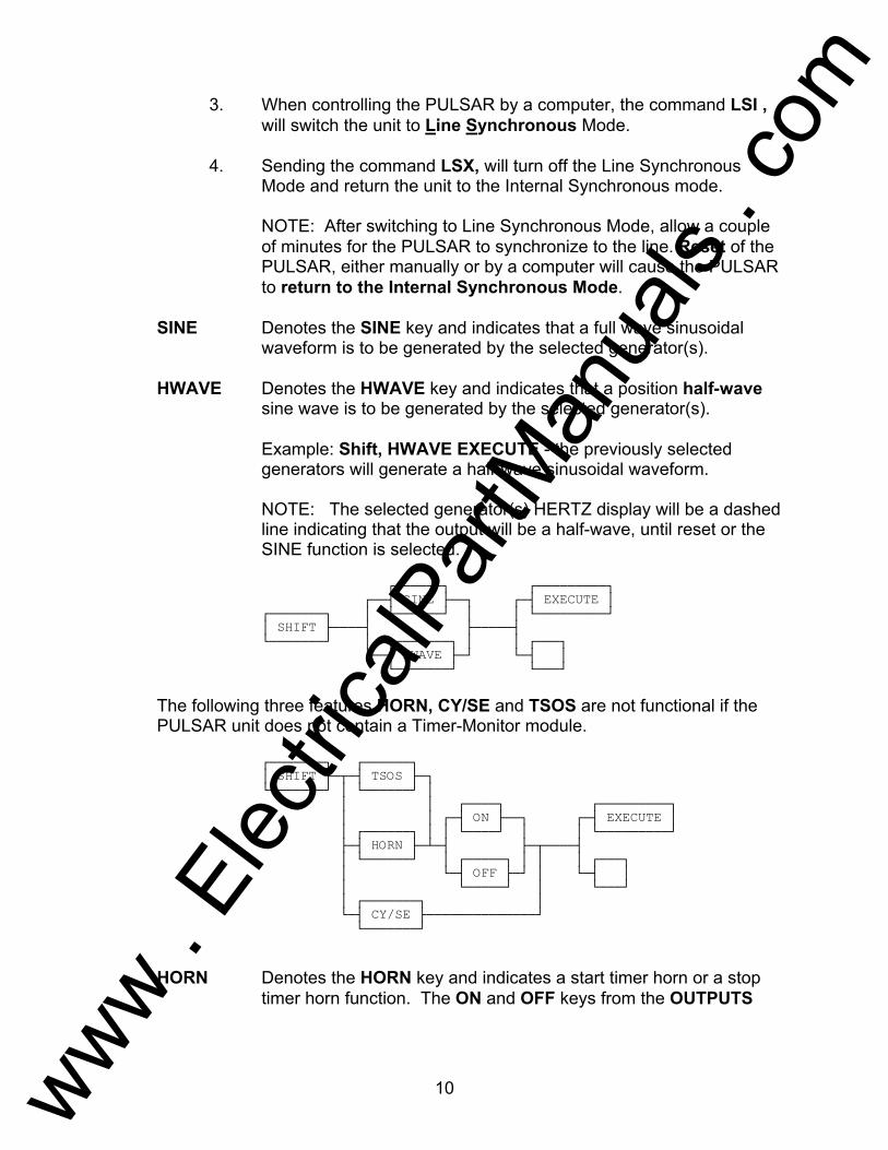
3. When controlling the PULSAR by a computer, the command LSI , will switch the unit to Line Synchronous Mode.
4. Sending the command LSX, will turn off the Line Synchronous
Mode and return the unit to the Internal Synchronous mode. NOTE: After switching to Line Synchronous Mode, allow a couple
of minutes for the PULSAR to synchronize to the line. Reset of the PULSAR, either manually or by a computer will cause the PULSAR to return to the Internal Synchronous Mode.
SINE Denotes the SINE key and indicates that a full wave sinusoidal
waveform is to be generated by the selected generator(s). HWAVE Denotes the HWAVE key and indicates that a position half-wave
sine wave is to be generated by the selected generator(s). Example: Shift, HWAVE EXECUTE - the previously selected
generators will generate a half-wave sinusoidal waveform. NOTE: The selected generator(s) HERTZ display will be a dashed
line indicating that the output will be a half-wave, until reset or the SINE function is selected.
SINE EXECUTE SHIFT HWAVE
The following three features HORN, CY/SE and TSOS are not functional if the PULSAR unit does not contain a Timer-Monitor module.
SHIFT TSOS ON EXECUTE HORN OFF CY/SE
HORN Denotes the HORN key and indicates a start timer horn or a stop timer horn function. The ON and OFF keys from the OUTPUTS
www . El
ectric
alPar
tMan
uals
. com

11
menu must follow the HORN key in order to activate and deactivate the timer horn.
Example: Shift, HORN, ON, EXECUTE. This key sequence will
turn the HORN on in association by the MONITOR (continuity).
CY/SE Denotes the CY/SE key (CYcles/SEconds) and indicates that the display output of the timer is toggled between cycles and seconds. In cycles mode an automatic division of the number of seconds by the period is performed. The period is known from the internal jumper selected frequency (50 or 60 Hz). In seconds mode the display output is in seconds. The default is seconds.
TSOS Denotes the TSOS (Timer Stop On Synchronization) key and
indicates that if the ON (located under OUTPUTS menu) key is pressed next:
the timer start gate will be activated when there is a change of
state. A change of state occurs when an input binding post changes from:
(a) continuity to no continuity; (b) no continuity to continuity; (c) voltage applied to voltage removed; (d) no voltage applied to voltage applied.
Example: When testing an auto-synchronizing relay, the Timer will start when the relay closes its contacts at the advanced angle.
the timer stop gate will be activated when the two selected
generators are synchronized (for the above example, the time indicated should be the closing time of the breaker).
If the OFF (under OUTPUTS menu) key is pressed next after the
TSOS key, this function is canceled.
RST PH Denotes the RST PH key; restores the phase relationship of all generators. When the frequency of a generator is changed, its phase relationship to the other generators will be unpredictable. To indicate this condition the generator whose frequency is changed will show dashes at its phase display. The phase will be restored when RST PH is executed.
www . El
ectric
alPar
tMan
uals
. com

12
EXECUTE SHIFT RST PH
The restoration of phase will occur at the next zero crossing of the master generator. Phase is automatically reset whenever all voltage and current generator outputs are off.
Example: Shift, RST PH, EXECUTE - restore the phase
relationship of all generators.
A-OFF Denotes the A-OFF (auto off) key and allows the user to have all outputs turned off whenever the stop gate of the timer-monitor changes state.
ON EXECUTE SHIFT A-OFF OFF
If used with the ON key, indicates that the A-OFF (AUTO OFF) function is in effect. And, if used with the OFF key, indicates that the A-OFF function is canceled.
Example: Shift, A-OFF, ON, EXECUTE - turn off all outputs
whenever the timer changes state.
OUTPUTS MENU:
Directly below the alpha-numeric keypad is the OUTPUTS menu which offers the following items:
ON The primary function of the ON key is to control the voltage and/or
current outputs. This key, along with the EXECUTE key turns selected generators' output (both AC and/or DC parameters) on.
It may also be used after the TSOS key or the HORN key. Its use
for the TSOS key has been explained earlier (see TSOS). For HORN key it indicates a timer horn enable, which applies to both start timer horn and stop timer horn. When enabled, the horn will sound whenever the timer input binding posts have voltage applied and/or continuity.
www . El
ectric
alPar
tMan
uals
. com

13
Can also be used with the A-OFF key (see A-OFF) to enable the
auto off function throughout a certain operation.
OFF The OFF key also controls the outputs of different PULSAR modules. Along with the EXECUTE key it turns off the outputs of selected generator(s).
It may also be used after the TSOS key or the HORN key. Its use
for the TSOS key has been explained earlier (see TSOS). For HORN key it indicates a timer horn disable which applies to both start timer horn and stop timer horn. When disabled, the horn will be disconnected from the timer input binding posts.
Can also be used with the A-OFF key (see A-OFF) to disable or
cancel the auto off function throughout a certain operation.
EXECUTE This key allows immediate execution of function(s). Any string of allowable and applicable keys that were pressed prior to pressing the EXECUTE key is executed immediately.
CANCEL Denotes the "CANCEL" key and it allows the cancellation of all
entered procedures since the previous EXECUTE key was depressed. It works in conjunction with the Shift i.e., it requires the Shift key as prefix. If no procedures were entered via keys since the last EXECUTE key was pressed, this function does nothing. If this function is entered more than once consecutively, it accomplishes no more than if it were entered once.
This procedure is unique in that it is executed immediately, i.e.,
without waiting for a subsequent execute key or the start of a subsequent procedure.
RAMP MENU: Located directly above the Shift key are the Ramp keys which allow the user to ramp up or down any selected output(s) that include AC/DC voltage, current, phase angle and frequency. It incorporates four up-arrow keys and four down-arrow keys that cause the previously selected generators to increment (if up-arrow) or decrement (if down-arrow) at the selected increment or decrement rates. The increment or decrement values vary depending on what is being ramped and what range the output is set for. When incrementing the amplitude or the phase angle, the top-most up-arrow key increments the most significant digit and the bottom-most up-arrow increments the least significant one. When incrementing, the bottom-most down-arrow key decrements the most significant digit and the top-most down-arrow key decrements the least significant one. The size of increment or decrement is determined by the RANGE. The ramp rate is set to 2 digits per second. For
www . El
ectric
alPar
tMan
uals
. com
14
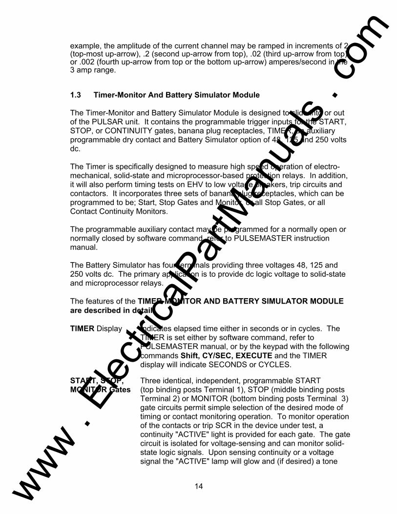
example, the amplitude of the current channel may be ramped in increments of 2 (top-most up-arrow), .2 (second up-arrow from top), .02 (third up-arrow from top) or .002 (fourth up-arrow from top or the bottom up-arrow) amperes/second in the 3 amp range. 1.3 Timer-Monitor And Battery Simulator Module The Timer-Monitor and Battery Simulator Module is designed to slide into or out of the PULSAR unit. It contains the programmable trigger inputs for the START, STOP, or CONTINUITY gates, banana plug receptacles, TIMER, an auxiliary programmable dry contact and Battery Simulator option of 48, 125 and 250 volts dc. The Timer is specifically designed to measure high speed operation of electro-mechanical, solid-state and microprocessor-based protection relays. In addition, it will also perform timing tests on EHV to low voltage breakers, trip circuits and contactors. It incorporates three sets of banana plug receptacles, which can be programmed to be; Start, Stop Gates and Monitor, or all Stop Gates, or all Contact Continuity Monitors. The programmable auxiliary contact may be programmed for a normally open or normally closed by software command, refer to PULSEMASTER instruction manual. The Battery Simulator has four terminals providing three voltages 48, 125 and 250 volts dc. The primary application is to provide dc logic voltage to solid-state and microprocessor relays. The features of the TIMER-MONITOR AND BATTERY SIMULATOR MODULE are described in detail: TIMER Display Indicates elapsed time either in seconds or in cycles. The
TIMER is set either by software command, refer to PULSEMASTER manual, or by the keypad with the following commands Shift, CY/SEC, EXECUTE and the TIMER display will indicate SECONDS or CYCLES.
START, STOP, Three identical, independent, programmable START MONITOR Gates (top binding posts Terminal 1), STOP (middle binding posts
Terminal 2) or MONITOR (bottom binding posts Terminal 3) gate circuits permit simple selection of the desired mode of timing or contact monitoring operation. To monitor operation of the contacts or trip SCR in the device under test, a continuity "ACTIVE" light is provided for each gate. The gate circuit is isolated for voltage-sensing and can monitor solid-state logic signals. Upon sensing continuity or a voltage signal the "ACTIVE" lamp will glow and (if desired) a tone
www . El
ectric
alPar
tMan
uals
. com

15
generator (horn) will sound. The power-up default states for the START/STOP and MONITOR gates are CONTINUITY, Change of State (Normally Open, N.O. closing or Normally Closed, N.C., opening). To change a gate to VOLTAGE, Change of State (Voltage Applied, Voltage Removed) see the following example. Example; change Timer Stop (Terminal 2, second set of terminals) to VOLTAGE, Applied. Use the following key strokes, Shift, TIMER START, 2, EXECUTE. The LED indicator should toggle from CONTINUITY to VOLTAGE. NOTE: To toggle back, repeat the above key strokes. The following modes are provided for the Start/Stop/Monitor Gates: a) Dry Contacts Open - timer starts, stops or continuity
indicator goes out at the opening of normally closed contacts or when conduction through a semiconductor device, such as a triac or a transistor, is interrupted.
b) Dry Contacts Close - timer starts, stops or continuity indicator glows at the closing of the normally open contacts or upon conduction through a semiconductor device such as a triac or a transistor.
c) Application or Removal of ac or dc voltage timer starts, stops or continuity indicator glows (application) or darkens (removal) upon the application or removal of either an ac or dc voltage. The voltage threshold is adjustable by turning the small pot located between the Red and Black binding posts from 1 to 4 volts, ac or dc positive going signal. A higher threshold voltage helps to eliminate false triggers due to noisy source. Lower thresholds allow starting and stopping of timer from TTL voltage signals. The maximum allowable voltage applied is 300 volts AC or 300 volts DC, limited by MOV transient protection.
d) The Timer can be started when turning on any (or all) selected generators. The Timer will stop and selected outputs turn off when using the A-OFF feature.
www . El
ectric
alPar
tMan
uals
. com
16
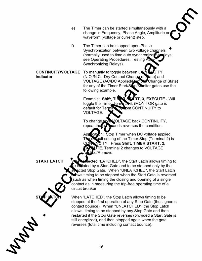
e) The Timer can be started simultaneously with a
change in Frequency, Phase Angle, Amplitude or a waveform (voltage or current) step.
f) The Timer can be stopped upon Phase Synchronization between two voltage channels (normally used to time auto synchronization relays, see Operating Procedures, Testing Auto-Synchronizing Relays).
CONTINUITY/VOLTAGE To manually to toggle between CONTINUITY Indicator (N.O./N.C. Dry Contact Change of State) and
VOLTAGE (AC/DC Applied/Remove Change of State) for any of the Timer Start/Stop/Monitor gates use the following example.
Example: Shift, TIMER START, 3, EXECUTE - Will
toggle the Timer Terminal 3, (MONITOR gate is default for Terminal 3) from CONTINUITY to VOLTAGE.
To change from VOLTAGE back CONTINUITY,
repeat the commands reverses the condition.
Application: Stop Timer when DC voltage applied. The default setting of the Timer Stop (Terminal 2) is CONTINUITY. Press Shift, TIMER START, 2, EXECUTE. Terminal 2 changes to VOLTAGE Applied/Remove.
START LATCH When selected "LATCHED", the Start Latch allows timing to
be initiated by a Start Gate and to be stopped only by the selected Stop Gate. When "UNLATCHED", the Start Latch allows timing to be stopped when the Start Gate is reversed (such as when timing the closing and opening of a single contact as in measuring the trip-free operating time of a circuit breaker.
STOP LATCH When "LATCHED", the Stop Latch allows timing to be
stopped at the first operation of any Stop Gate (thus ignores contact bounce). When "UNLATCHED", the Stop Latch allows timing to be stopped by any Stop Gate and then restarted if the Stop Gate reverses (provided a Start Gate is still energized), and then stopped again when the gate reverses (total time including contact bounce).
www . El
ectric
alPar
tMan
uals
. com

17
TIMER Reset The Timer is defaulted to automatically reset when the TIMER START, EXECUTE Keys are pressed. Should it be desired to Reset the Timer due to change of the Time Start/Stop terminals (i.e. change from Normally Open, N.O., to Normally Closed, N.C.) condition, then the operator will need to manually reset the Timer using the following key strokes, Shift, 6, EXECUTE. NOTE: The number 6 key does not have a Blue Function shown. Think of it as the Timer Reset function key.
START/STOP The timer can be programmed to ignore temporary state GATE DE- changes that are less than a programmable duration. BOUNCE This is useful for eliminating false triggering and contact
bounce errors. De-bounce Period: 0 to 999 milliseconds. Resolution: 0.1 ms. AUXILIARY A pair of banana receptacles provide access to the CONTACT programmable dry contacts. The contacts may be opened
or closed by software command, refer to the PULSEMASTER instruction manual.
Maximum Switching Voltages: 110 volts AC or 30
volts DC. Maximum Switching Currents: 0.3 amps AC or 1.0
amps DC. Opening Time: 0.5 ms typical. Closing Time: 1 ms typical.
BATTERY Four banana plug receptacles provide the following SIMULATOR voltages 48, 125 and 250 volts dc. Only one output voltage
may be used at a time. The maximum output power is 60 watts.
NOTE: dc voltage is ON and available when PULSAR is turned on by the ON/OFF switch. Do not plug or insert any test lead into the BATTERY SIMULATOR binding posts without first connecting the test leads to the load!
www . El
ectric
alPar
tMan
uals
. com

18
1.4 Voltage Generator Module The Voltage Generator Module is also designed to slide into or out of, a single PULSAR module slot. One module can provide either ac or dc voltage output of 0 to 30 VoltsRMS or 0 to 300 VoltsRMS. VOLTS Display This four digit LED display indicates the amplitude of the
voltage output.
DEGREES Display This four digit LED display indicates the phase angle of the voltage output in positive phase rotation angles. Where V1 is 0.0°, V2 is 120.0°, and V3 is 240.0° (V2 lags V1 by 120.0° and V3 leads V1 by 120.0°).
FREQUENCY Display This five digit LED display indicates the frequency of
the voltage output. For DC voltage the display will show zero.
STATUS Display Located right below the Frequency display is the
STATUS display, which displays output status (on or off) and DC offset when applicable.
Red and White Voltage Binding Posts
Provides for connection to voltage output. The White binding post is grounded and should be used as the instantaneous non-polarity terminal with the red terminal as polarity. The ground (earth) terminal is connected to the chassis ground.
Error Indication and Circuitry is incorporated to indicate whenever Alarm the amplitude, phase angle, and/or waveform of the
voltage source is in error. When an error is detected, the amplitude display will flash and the alarm will sound.
1.5 Current Generator Module The Current Generator Module is also designed to slide into the PULSAR unit. Each current module takes up two slots of a PULSAR unit. One module can provide either ac or dc current output, 0 to 3 amperes, 0 to 15 amperes or 0 to 30 amperes.
AMPERES Display This four digit LED display indicates the amplitude of
the current output.
www . El
ectric
alPar
tMan
uals
. com

19
DEGREES Display This four digit LED display indicates the phase angle of the current output.
FREQUENCY Display This five digit LED display indicates the frequency of
the current output. For dc current the display will show dc.
STATUS Display Located right below the Frequency display is the
STATUS display, which displays output status (on or off) and DC offset when applicable.
Black and White Current Binding Posts
Provides for connection to current output. The White binding post is grounded and used as the instantaneous non-polarity terminal with the Black terminal as polarity. The ground (earth) terminal is connected to the chassis ground.
Error Indication and Circuitry is incorporated to indicate whenever Alarm the amplitude, phase angle, and/or waveform of the
current source is in error. When the error is detected, the amplitude display will flash and the alarm will sound.
1.6 High Current Interface Module The High Current Interface Module is designed to slide into the PULSAR unit. Each Module takes up 1 slot of the unit. See installation instructions below. The Module is designed to interface with the AVO Multi-Amp Models EPOCH-20 or EPOCH-II, High-Current Output Units (see EPOCH-20 or EPOCH-II Bulletins for output specifications). This module provides control of the EPOCH-20 or EPOCH-II current amplitude, phase angle and frequency output. Status of the EPOCH-20/II output can be seen on the front panel display. AMPERES Display This four digit LED display indicates the amplitude of
the current output.
DEGREES Display This four digit LED display indicates the phase angle of the current output.
FREQUENCY Display This five digit LED display indicates the frequency of
the current output.
NOTE: The EPOCH-20 or EPOCH-II output frequency is limited to 5 Hz. (lowest output frequency). The output compliance voltage and Volt-Ampere output is derated linearly to 50 % of specification from 40 Hz. to 20 Hz.
www . El
ectric
alPar
tMan
uals
. com

20
INSTALLATION To install the interface module may require the removal of another output module, see Section F, REPAIR DATA, Removal of Current Amplifier Module for instructions to remove the output module from the chassis. Since the current output module takes up two slots and the interface module only uses one, a blank module is required to fill the void slot. If the interface module was ordered separately, then it is provided with a blank module. WARNING: The blank module must be installed in the empty slot prior to
operating the unit, since dangerous high voltage is present on the inside back plane connector.
NOTE: Remove Current Output Module #1 for use with PulseMaster software.
To install the interface and blank modules, carefully slide the modules into the chassis. Make sure they are properly seated into the back plane connectors by pressing firmly on the front of the module. Screw back panel knurl knobs onto the interface and blank modules. Reinstall front panel screws.
Hardware interface connections are made on the back of each unit using the interface cable provided in the accessory kit. The cable connectors fit the EPOCH-20 interface connectors. An adapter connector mates with the interface cable to connect to the EPOCH-II signal INPUT connector.
OPERATION
Turn ON the PULSAR, all current and voltage modules except for the EPOCH-20/II HIGH CURRENT INTERFACE MODULE will display zeroes and system frequency. The high current module will have dashed lines (- - - -) in the amperes display. Turn ON the EPOCH-20/II test set then press the Reset button on the PULSAR, the dashed lines will be replaced with zeroes. The unit is now ready to use. Refer to the EPOCH-20/II Instruction Manuals for proper operation.
When a relay test is completed and the HIGH CURRENT INTERFACE MODULE is no longer required, turn OFF the EPOCH-20/II test unit. If a DC target test is required and if you are using PulseMaster, with the EPOCH-20/II off (EPOCH-20/II cannot provide DC current, but PULSAR current modules can) press the Reset button on the PULSAR. This will cause PULSAR to default to the second current module. The test can now be conducted.
The HIGH CURRENT INTERFACE MODULE can be left in the left most slot until further needed. The second and third current modules can be used to do other relay testing. When using PulseMaster, always remember to press the Reset button on the PULSAR before accessing another high current relay test file.
www . El
ectric
alPar
tMan
uals
. com

21
1.7 Back Panel
The input line cord, ground terminal, interconnecting plugs, and RS-232C port are mounted on the back panel of the test set. The following is a description of each item.
Input Line Cord
The test set is equipped with a suitable line cord which is part of the accessory kit, it connects to the male plug on the back panel. Verify input voltage before connecting the line cord to the source of power. NOTE: Unit can be powered up from an input source with a rating of 95 Vac to 265 Vac. PULSAR can automatically select (or adjust to) the available power if it is within the specified range mentioned above.
Unit is equipped with an internal fuse.
A chassis ground (earth) point on the back
panel is provided as an additional safety ground. A ground is provided at the input power connection.
IEEE-488 GPIB (Optional) The optional General Purpose Interface Bus Bus Connection (GPIB) enables the PULSAR to function as a
talker-listener with any controller or computer which conforms to the IEEE-488 Bus connector.
The significant benefit for having this option will
enables the user to download DFR and EMTP files faster than using the RS-232 port.
SERIAL INTERFACE Provides communication port for control by computer.
PULSAR requires a straight 9 pin, female to female communication cable. See Appendix A for PULSAR Remote Operation Command Set and communication protocol.
SYNC IN Used with the Sync Out from another PULSAR unit or
other TTL (+ 5Vdc) signal source (Trigger from a GPS satellite receiver). Primarily used to trigger an operation or programmed event.
www . El
ectric
alPar
tMan
uals
. com
22
SYNC OUT Used to provide a TTL signal to another PULSAR unit for multiple box operation.
CLOCK IN Used with the Clock Out from another PULSAR unit
or other Clock Source for special testing applications. Normally used for multiple box operation to phase lock.
CLOCK OUT Used to provide a 214.7 Khz clock signal to another
PULSAR unit for phase locking multiple boxes.
EXPANSION INTERFACE Provided for future expansion and special applications.
Analog Connectors Each output module has a 3 pin, female, mini-DIN
connector. An analog signal of ± 5 Vpeak = Full Scale output.
CAUTION: Do not exceed ± 5 Vpeak! Do not apply a
square wave with a 5 Vpeak. To do so will cause damage to the amplifier. If square waves are required, it is recommended that 3.5 to 4 Vpeak not be exceeded. Contact factory for details regarding pin connections.
B. INITIAL SET-UP
Unpack the unit and check for any evidence of shipping damage. If visual damage is present, notify freight carrier to make damage claims. Also, notify the factory. The covers are easily removable for access to the front and back panels.
CAUTION
Potentially lethal voltages can be present on the output terminals. It is recommended that the operator thoroughly read the instruction manual and understand the operation of the test set before energizing. An operational check may be performed as follows to verify that the amplitude, phase angle and monitor circuits are functioning properly.
www . El
ectric
alPar
tMan
uals
. com
23
1. Before plugging in the unit, make sure the POWER ON/OFF Switch is OFF.
2. Plug the line cord for the test set into a suitable source of power and
switch the POWER ON/OFF Switch ON. 3. It is recommended that all the current and voltage amplitudes and phase
angle controls be checked using external instrumentation before placing unit in service.
SELECTION OF MASTER MODULE
When the unit comes from the factory, there will be a generator module (either current or voltage) in the lower right-hand corner of the unit for phase synchronization. If you want to change the configuration (i.e., re-arrange the placement of the modules) you must have a module in the lower right-hand corner slot, see DESCRIPTION of CONTROLS, SYNC/Phase Reference.
C. OPERATING PROCEDURES
Introduction
After thoroughly reviewing the theory of operation section of this instruction manual, the operator should have a good understanding of the operation of PULSAR.
Use of PULSAR
This section describes basic operating procedures for using the multiple output modules of the PULSAR Test Set for such applications as paralleling current outputs, conducting harmonic restraint tests, series of potential sources to provide higher than rated potential, testing over/under voltage relays and forming three phase voltage outputs.
1.0 Setting Phase Angle Relationships
Think of each PULSAR module as a vector generator. Each module has an internal zero reference to which it references its phase angle settings, as displayed on the LED readouts. This applies to phase angle settings between the voltage and current modules of a PULSAR. When setting a phase angle between two modules of a PULSAR unit, it is recommended that one module be set at zero degree and the other module be referenced to that module at zero degree. This is for operator convenience and reduces confusion. When setting an angle, the operator has a choice of setting the angle either in the
www . El
ectric
alPar
tMan
uals
. com
24
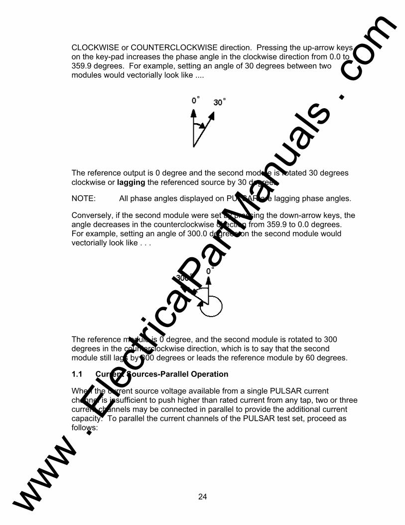
CLOCKWISE or COUNTERCLOCKWISE direction. Pressing the up-arrow keys on the key-pad increases the phase angle in the clockwise direction from 0.0 to 359.9 degrees. For example, setting an angle of 30 degrees between two modules would vectorially look like ....
The reference output is 0 degree and the second module is rotated 30 degrees clockwise or lagging the referenced source by 30 degrees.
NOTE: All phase angles displayed on PULSAR are lagging phase angles.
Conversely, if the second module were set by pressing the down-arrow keys, the angle decreases in the counterclockwise direction from 359.9 to 0.0 degrees. For example, setting an angle of 300.0 degrees on the second module would vectorially look like . . .
The reference module is 0 degree, and the second module is rotated to 300 degrees in the counterclockwise direction, which is to say that the second module still lags by 300 degrees or leads the reference module by 60 degrees.
1.1 Current Sources-Parallel Operation
When the current source voltage available from a single PULSAR current channel is insufficient to push higher than rated current from any tap, two or three current channels may be connected in parallel to provide the additional current capacity. To parallel the current channels of the PULSAR test set, proceed as follows:
www . El
ectric
alPar
tMan
uals
. com
25
1. Using the current channel test leads, connect each current channel to the
relay under test. The parallel connection must be made at the relay not at the source. Also, note that all current sources White binding posts are grounded.
2. Switch PULSAR ON.
3. Set the current channels to be used in parallel such that for using two
current channels the settings between the two outputs will be one-half and the settings between three current channels will be one-third. Initiate all of the PULSAR current channels together by pressing the following keys CURRENT, 0, ON, EXECUTE. All parallel current outputs must be ON to prevent internal shunting of current.
NOTE: All current channels should be set to the same phase angle.
4. All current channels amplitude control now operates simultaneously to
provide the desired test current. Total output is the sum of the current displayed on the current channels amplitude display.
1.2 Current Sources-Harmonic Restraint Test
NOTE: To obtain the desired current output necessary to conduct harmonic restraint tests on differential relays, two PULSAR current channels must be used, one current channel will provide the harmonic output and the second current channel will provide the fundamental or "by-pass" current. There are two methods available in PULSAR to do harmonic restraint tests. One method uses a pure harmonic (2nd, 3rd, 5th, etc) of the fundamental from one current channel, summed with the fundamental current from a second current channel at the relay. The second method uses the PULSAR "HWAVE" feature. The HWAVE simulates the "diode method" recommended in some relay manufacturers instruction literature. When the HWAVE is selected, the selected output module will provide a "half-wave" sinewave (similar to what you would see if using a diode in series with a current source).
NOTE: Most recommended test procedures suggest using 4 amperes DC of half-wave. Since PULSAR displays the full RMS sine-wave quantity, it will be necessary to set 8.89 amperes RMS on the selected HWAVE current channel in order to get the desired equivalent 4 amperes DC half-wave. To calculate other values of DC half-wave use the following formulas,
www . El
ectric
alPar
tMan
uals
. com

26
Idc (half-wave) = Ipeak / π and Ipeak = Irms * 1.414
Therefore, Idc (half-wave) = Irms * 1.414 / π
or, Irms = Idc (half-wave) / 0.45
Solving, Idc = 4
Irms = 4 / 0.45
Irms = 8.89
To set up the PULSAR for harmonic restraint testing, use the following procedure:
1. Switch the POWER ON/OFF Switch ON.
2. Select one of the current modules to provide the desired harmonic. Set
the current channel to the desired harmonic either second, third, or fifth in conjunction with the FREQ. selector switch. For example, use the following keystrokes to set Current Channel #2 to the second harmonic of 60 Hz; CURRENT, 2, FREQ, 120, Shift, RST.PH., EXECUTE. If using the HWAVE feature set; CURRENT, 2, Shift, HWAVE, EXECUTE.
3. Connect a pair of current output leads from two of the PULSAR current
channels to the relay, so that current from each output will be in parallel with one restraint and the operating coil of the relay. Check to insure both commons (grounds or earths) share the same relay terminal.
4. Initiate the outputs. The output "ON" light should be displayed on the
current amplifier front panel.
5. Increase the output to the appropriate harmonic current. It is recommended that one ampere of harmonic current be set (it will make the math easier). If using the HWAVE, set the displayed current to 8.89 amperes RMS (this equals 4 amperes DC half-wave).
6. Increase the fundamental current until the relay operates. To calculate the
percent of harmonic restraint use the appropriate equation below (if using pure harmonic current). If using the HWAVE refer to the manufacturers instruction literature for the appropriate % Harmonic Curve.
Type BDD %Harmonic = 2nd Harmonic Current x 100 √(Fundamental)2 + (2nd Harmonic)2
www . El
ectric
alPar
tMan
uals
. com
27
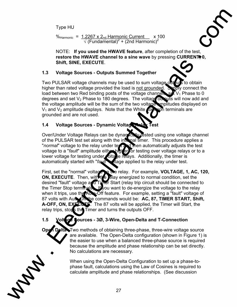
Type HU %Harmonic = 1.2267 x 2nd Harmonic Current x 100 √ (Fundamental)2 + (2nd Harmonic)2 NOTE: If you used the HWAVE feature, after completion of the test,
restore the HWAVE channel to a sine wave by pressing CURRENT, 0, Shift, SINE, EXECUTE.
1.3 Voltage Sources - Outputs Summed Together
Two PULSAR voltage channels may be used to sum voltage outputs to obtain higher than rated voltage provided the load is not grounded. Simply connect the load between two Red binding posts of the voltage channels, set V1 Phase to 0 degrees and set V2 Phase to 180 degrees. The voltage outputs will now add and the voltage amplitude will be the sum of the two voltage amplitudes displayed on V1 and V2 amplitude displays. Note that the White common terminals are grounded and are not used.
1.4 Voltage Sources - Dynamic Voltage Relay Test
Over/Under Voltage Relays can be dynamically tested using one voltage channel of the PULSAR test set along with the internal timer. This procedure applies a "normal" voltage to the relay under test and then automatically adjusts the test voltage to a "fault" amplitude either higher for testing over voltage relays or to a lower voltage for testing under voltage relays. Additionally, the timer is automatically started with "fault" voltage applied to the relay under test.
First, set the "normal" voltage on the relay. For example, VOLTAGE, 1, AC, 120, ON, EXECUTE. Then, with the relay energized to normal condition, set the desired "fault" voltage and Timer Start (relay trip circuit should be connected to the Timer Stop terminals). If you want to de-energize the voltage to the relay when it trips, use the Auto-Off feature. For example, setting a "fault" voltage of 87 volts with Auto-Off the commands would be: AC, 87, TIMER START, Shift, A-OFF, ON, EXECUTE. The 87 volts will be applied, the Timer will Start, the relay trips, stops the Timer and turns the outputs OFF.
1.5 Voltage Sources - 3Ø, 3-Wire, Open-Delta and T-Connection
Open Delta Two methods of obtaining three-phase, three-wire voltage source
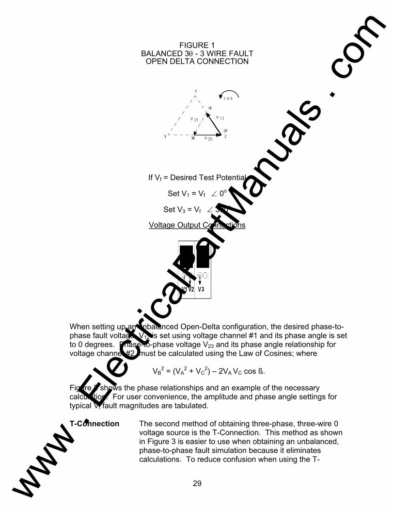
are available. The Open-Delta configuration (shown in Figure 1) is the easier to use when a balanced three-phase source is required because the amplitude and phase relationship can be set directly. No calculations are necessary.
When using the Open-Delta Configuration to set up a phase-to-
phase fault, calculations using the Law of Cosines is required to calculate amplitude and phase relationships. (See discussion
www . El
ectric
alPar
tMan
uals
. com

28
under T-Connection for simulating unbalanced, phase-to-phase faults without need for calculations.)
When using the Open-Delta configuration, it is suggested the
voltage channel #1 Red binding post is designated V1, voltage channel #2 Red binding post is designated V3, while either White COMMON binding post is designated V2. With this arrangement, the magnitude and phase angle of the potentials can be easily calculated and set. For the balanced three-phase condition V12 and V23 are equal in magnitude and separated by an angle of 60o. This is done by setting the V1 and V3 potentials equal in magnitude, setting 0 degrees on V1 and 300o (60 degrees leading) on V3, (see Figure 1).
www . El
ectric
alPar
tMan
uals
. com
29
FIGURE 1 BALANCED 3θ - 3 WIRE FAULT OPEN DELTA CONNECTION If Vf = Desired Test Potential Set V1 = Vf ∠ 0o Set V3 = Vf ∠ 300o Voltage Output Connections
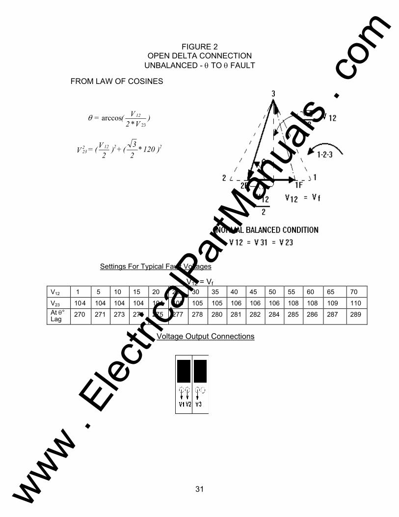
When setting up an unbalanced Open-Delta configuration, the desired phase-to-phase fault voltage, V12 is set using voltage channel #1 and its phase angle is set to 0 degrees. Phase-to-phase voltage V23 and its phase angle relationship for voltage channel #2, must be calculated using the Law of Cosines; where
VB2 = (VA
2 + VC2) – 2VA VC cos ß.
Figure 2 shows the phase relationships and an example of the necessary calculation. For user convenience, the amplitude and phase angle settings for typical Vf fault magnitudes are tabulated. T-Connection The second method of obtaining three-phase, three-wire 0
voltage source is the T-Connection. This method as shown in Figure 3 is easier to use when obtaining an unbalanced, phase-to-phase fault simulation because it eliminates calculations. To reduce confusion when using the T-
www . El
ectric
alPar
tMan
uals
. com

30
Connection, it is suggested that voltage output #1 be designated Va and its phase angle set at 0 degrees, voltage output #2 be designated Vb and its phase angle set for 180 degrees and voltage output #3 be designated Vc and its phase angle is set for 270 degrees; any combination of balanced 3θf or unbalanced θ - θ fault conditions can be easily simulated. Figure 3 shows the phase relationships.
NOTE: This method is not good for very low fault voltages,
i.e., 5 volts or less, or for testing ABB (WESTINGHOUSE) type SKD relays.
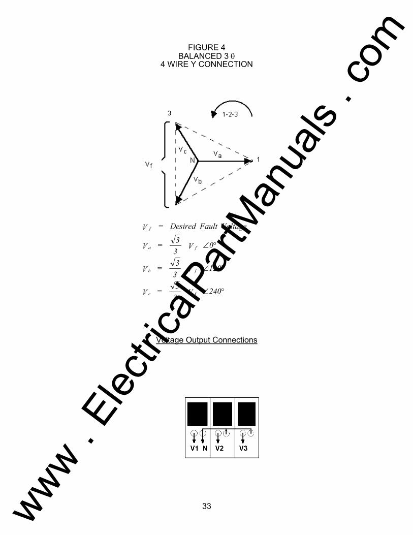
1.6 Voltage Source - 3Ø, 4-Wire, Y-Connection A three-phase, four-wire potential system can be provided using three output modules. The vector relationships are shown in Figure 4. This Y-Connection has the advantage of being able to supply higher line-to-line voltage (1.73 x phase-to-neutral voltage) and is ideally suited for simulating phase to ground faults. Voltage channel #1 is designated as Va with its phase relationship set for 0 degrees. Voltage channel #2 is then designated as Vb and phase angle set for 120 degrees. Finally, voltage channel #3 is designated Vc and phase angle set for 240 degrees (for a 1-2-3 counter clockwise rotation). Va, Vb and Vc are then connected to the Red potential binding posts on the respective test sets. If a neutral is required, it is connected to a White potential section binding post on any voltage output module to ground the load.
www . El
ectric
alPar
tMan
uals
. com
31
FIGURE 2 OPEN DELTA CONNECTION UNBALANCED - θ TO θ FAULT FROM LAW OF COSINES
Settings For Typical Fault Voltages V12 = Vf
V12 1 5 10 15 20 25 30 35 40 45 50 55 60 65 70
V23 10 4 104 104 104 104 105 105 105 106 106 106 108 108 109 110 At θ° Lag
270 271 273 274 275 277 278 280 281 282 284 285 286 287 289
Voltage Output Connections
232 12 2 2V = (V
2) +( 3
2*120 )
)V2
V(= 12
23*arccosθ
www . El
ectric
alPar
tMan
uals
. com

32
FIGURE 3 BALANCED OR UNBALANCED FAULT T-CONNECTION Voltage Output Connections
fV = Desired Fault Voltage
a fV = 12
V 0∠ °
°∠180 V21 = V fb
c cV = 32
120 or V = 104V 270∠ °
www . El
ectric
alPar
tMan
uals
. com
33
FIGURE 4 BALANCED 3 θ 4 WIRE Y CONNECTION
Voltage Output Connections
fV = Desired Fault Voltage
a fV = 33
V 0∠ °
b fV = 33
V 120∠ °
c fV = 33
V 240∠ °
www . El
ectric
alPar
tMan
uals
. com
34
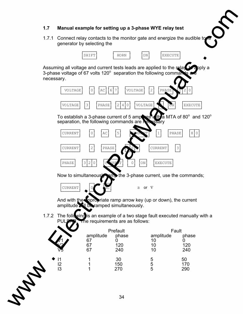
1.7 Manual example for setting up a 3-phase WYE relay test
1.7.1 Connect relay contacts to the monitor gate and energize the audible tone generator by selecting the
SHIFT HORN ON EXECUTE Assuming all voltage and current tests leads are applied to the relay, to apply a
3-phase voltage of 67 volts 120o separation the following commands are necessary.
VOLTAGE 0 AC67 VOLTAGE 2 PHASE 120 VOLTAGE 3 PHASE 240 VOLTAGE 0 ON EXECUTE
To establish a 3-phase current of 5 amperes with a MTA of 80o and 120o separation, the following commands are necessary
CURRENT 0 AC 5 CURRENT 1 PHASE 80 CURRENT 2 PHASE 200 CURRENT 3 PHASE 320 CURRENT 0 ON EXECUTE
Now to simultaneously ramp the 3-phase current, use the commands; CURRENT 0 AC ≅ or ∇
And with the appropriate ramp arrow key (up or down), the current amplitude will be ramped simultaneously.
1.7.2 The following is an example of a two stage fault executed manually with a
PULSAR. The requirements are as follows: Prefault Fault amplitude phase amplitude phase V1 67 0 10 0 V2 67 120 10 120 V3 67 240 10 240 I1 1 30 5 50 I2 1 150 5 170 I3 1 270 5 290
www . El
ectric
alPar
tMan
uals
. com

35
The following abbreviations will be used too for the PULSAR keypad. VOLTAGE GENERATOR = v CURRENT GENERATOR = c AC AMPLITUDE = a PHASE = p EXECUTE = ;
Example This series of pushbuttons applies the prefault conditions. v2,p120,v3,p240,v0,a67,on,c1,p30,c2,p150,c3,p270,c0,a1,on; This series of pushbuttons loads and executes the fault conditions. Only those parameters to be changed had to be entered. v0,a10,c0,a5,c1,p50,c2,p170,c3,p290;
1.8 Testing Sync-Check, Synchronizing and Auto-Synchronizing
Relays:To perform tests on synchronizing type relays requires the use of two voltage output modules.
Pick-up or Closing Angle Tests: To perform Pick-up or Closing Angle
tests let one voltage channel be the 0° reference, i.e., V1, and let the second voltage channel provide the variable phase angle adjustment, i.e., V2. Remember the phase angle indicated on V2 will be a lagging angle (see SETTING PHASE ANGLE RELATIONSHIPS). If the relay's closing characteristic is 20° leading, set an angle of 340° on voltage channel 2.
To set V1 and V2 to 120 volts each and turn on use the following keystrokes, VOLTAGE, 1,2, AC, 120, ON, EXECUTE To set V2 to a phase angle of 340° lag (20° lead) use the following keystrokes, VOLTAGE, 2, PHASE, 340, EXECUTE To ramp the phase angle of V2 toward 0°, press and hold the appropriate RAMP arrow until the relay picks up, i.e., 345° (15° leading)
Setting Advance Time: To perform this test let voltage channel 2, V2, provide the slip frequency (generator) and let voltage channel 1, V1, provide the fixed voltage/frequency source (bus). Connect the relay's closing contacts to Timer Start Terminal 1 (top pair of terminals), so that when the relay contacts close (at the advance angle) it will start the timer. Set V1 to the appropriate voltage output and turn on. For example: VOLTAGE, 1, AC, 120, ON, EXECUTE. Set V2 to an appropriate output voltage and slip frequency, but do not turn on yet. For example: VOLTAGE, 2, AC, 120, FREQ, 60.100, EXECUTE. V2 DEGREES display
www . El
ectric
alPar
tMan
uals
. com
36
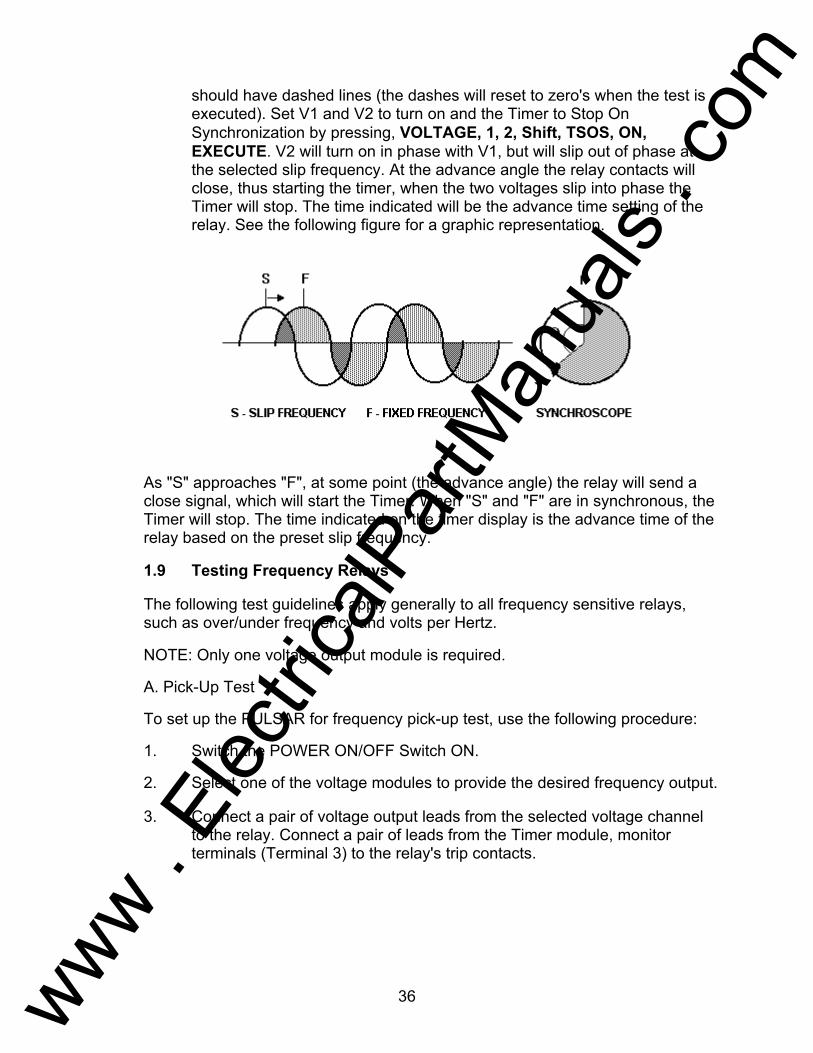
should have dashed lines (the dashes will reset to zero's when the test is executed). Set V1 and V2 to turn on and the Timer to Stop On Synchronization by pressing, VOLTAGE, 1, 2, Shift, TSOS, ON, EXECUTE. V2 will turn on in phase with V1, but will slip out of phase at the selected slip frequency. At the advance angle the relay contacts will close, thus starting the timer, when the two voltages slip into phase the Timer will stop. The time indicated will be the advance time setting of the relay. See the following figure for a graphic representation.
As "S" approaches "F", at some point (the advance angle) the relay will send a close signal, which will start the Timer. When "S" and "F" are in synchronous, the Timer will stop. The time indicated on the timer display is the advance time of the relay based on the preset slip frequency.
1.9 Testing Frequency Relays
The following test guidelines apply generally to all frequency sensitive relays, such as over/under frequency and volts per Hertz.
NOTE: Only one voltage output module is required.
A. Pick-Up Test To set up the PULSAR for frequency pick-up test, use the following procedure: 1. Switch the POWER ON/OFF Switch ON. 2. Select one of the voltage modules to provide the desired frequency output. 3. Connect a pair of voltage output leads from the selected voltage channel
to the relay. Connect a pair of leads from the Timer module, monitor terminals (Terminal 3) to the relay's trip contacts.
www . El
ectric
alPar
tMan
uals
. com

37
4. Set the desired output voltage and initiate the output. For example, use
the following keystrokes, VOLTAGE, 1, AC, 120, Shift, SZ, ON, EXECUTE. The output "ON" light should be displayed on the voltage amplifier front panel.
NOTE: The SZ (Self Zero) function was selected. This is important. All changes made to the frequency will take place at the positive zero crossing. Most solid-state and microprocessor-based frequency relays determine frequency and timing based on zero crossings.
5. Increase or decrease the output frequency to the appropriate value by
selecting FREQ then press the respective ∆ or ∇ RAMP buttons until the relay indicates pick-up.
B. Timing Test Over/Under Frequency Relays can be dynamically tested using one voltage channel of the PULSAR test set along with the timer module. This procedure applies a "normal" voltage and frequency to the relay under test and then automatically adjusts the test voltage to a "fault" frequency, either higher for testing over frequency relays, or to a lower frequency for testing under frequency relays. It should also be noted that the voltage amplitude can be changed with the frequency for more realistic dynamic testing. The timer is automatically started with "fault" frequency applied to the relay under test. To set up the PULSAR for frequency timing test, use the same set-up as for the pick-up test (except move the Monitor leads from Timer Terminal 3 to Timer Stop Terminal 2) and the following procedure: 1. Set the "normal" voltage on the relay. For example, VOLTAGE, 1, AC,
120, Shift, SZ, ON, EXECUTE (see NOTE above relative to the SZ mode).
2. With the relay energized to normal condition, set the desired "fault"
frequency / voltage and Timer Start (relay trip circuit should be connected to the Timer Stop terminals, Terminal 2). If you want to de-energize the voltage to the relay when it trips, use the Auto-Off feature. For example, setting a "fault" frequency of 58.880 Hz with Auto-Off the commands would be: FREQ, 58.88, TIMER START, Shift, A-OFF, ON, EXECUTE. The 58.880 Hz. will be applied, the Timer will Start, the relay trips, stops the Timer and turns the outputs OFF. The Time indicated on the display is the operating time of the relay.
3. To do a re-test, reset the frequency to the "normal" frequency using the
following keystrokes, FREQ, 60, Shift, RST .PH., ON, EXECUTE. Repeat step 2.
www . El
ectric
alPar
tMan
uals
. com

38
NOTE: The RST.PH. function was selected to restore phase angle relationship. This is required if conducting a dynamic frequency timing test using three-phase voltage and/or current.
APPLICATION NOTE: To conduct a more dynamic test including a change in voltage amplitude (i.e. change frequency to 50 Hz and amplitude to 100 volts) see the following. In step 2 "setting a fault" use the following keystrokes, AC, 100, FREQ, 50, TIMER START, Shift, A-OFF, ON, EXECUTE. The voltage will change to 100 volts at 50 Hz and the Timer will start all at the same time.
4. Once all tests are completed, restore SYNC to Phase Reference using the
following key strokes, Shift, PR, EXECUTE.
2.0 Testing DC Target And Seal-In
The following test guidelines apply generally to all DC target and seal-in elements. At least one current channel is required to do the target and seal-in test. If two current channels are available, use one current to provide AC current to close the trip contacts and use the other to provide the DC current. The following procedure is based on having two currents available. NOTE: If two currents are not available, block the trip contacts closed prior to conducting test. Remember to remove the block after the test is completed. 1. Switch the POWER ON/OFF Switch ON.
2. Select one of the current output channels to provide the AC current (for
this example current channel 1). Connect a pair of leads to the appropriate relay terminals to energize the relay trip element.
3. Connect current channel 2 to the appropriate relay terminals to energize
the DC target and seal-in elements.
4. Set the desired AC test current to approximately 150 % of the relay tap value and turn on. For example, if the relay tap setting is 4 Amperes, use the following keystrokes, CURRENT, 1, AC, 6, ON, EXECUTE.
5. When the relay trip element contacts close, energize the relay target coil
with DC using the following keystrokes, CURRENT, 2, DC, ON, EXECUTE. Ramp up the DC current using the appropriate RAMP Arrow key until the target drops and the seal-in coil picks-up, read and record the DC amperes.
www . El
ectric
alPar
tMan
uals
. com
39
6. Turn off current channel 1 using the following keystrokes, CURRENT, 1, OFF, EXECUTE. Note that the seal-in element should still be picked-up. Turn channel 1 back on by pressing ON, EXECUTE.
7. Select current channel 2 using the following keystrokes, CURRENT, 2,
DC, EXECUTE. Slowly reduce the DC current, by pressing the appropriate RAMP arrow key down until the target element drops out, read and record drop out current.
8. Turn current channels 1 and 2 off using the following keystrokes,
CURRENT, 1, 2, OFF, EXECUTE. Turn test set off.
D. SERVICE DATA
1.1 Servicing
The PULSAR utilizes surface mount technology (SMT) and components which require little or no service except for routine cleaning, tightening of connections, etc. The PULSAR should be serviced in a clean atmosphere away from energized electrical circuits. The following maintenance is recommended:
1. Examine the unit every six months for: a. Dust and other particulate matter collecting on the fins of the heat
sinks. b. Moisture condensation inside the lens covers of the display(s). c. Corrosion on the exposed metal surfaces. 2. Remove dust with dry, low pressure, compressed air. Either remove the
module from the chassis or simply apply air through the louvers on the front of the module forcing the dust out the rear.
3. Remove moisture as much as possible by putting the test set in a warm,
dry environment. 4. As corrosion may take many forms, no specific recommendations can be
made for its removal.
1.2 Service and Repair Order Instructions
If factory service is required or desired, contact the factory for return instructions.
A Repair Authorization (RA) number will be assigned for proper handling of the unit when it arrives at the factory.
If desired, a letter with the RA number and instructions can be provided.
www . El
ectric
alPar
tMan
uals
. com

40
Provide the factory with model number, serial number, nature of the problem or service desired, return address, your name, and where you can be reached should the factory need to contact you. If desired, you may also provide a purchase order number, cost limit, billing, and return shipping instructions.
National Institute of Standards and Technology (NIST) traceable calibration and certification of two types is available, if desired, at additional cost.
Class One: A certificate is provided verifying the traceability and calibration of the equipment.
Class N: That which is required for nuclear power plants. A certificate of traceability and calibration along with "as found" and "as left" data are provided.
If an estimate is requested, provide the name and contact information of the person with approval/disapproval authority.
Pack the equipment appropriately to prevent damage during shipment. If a reusable crate or container is used, the unit will be returned in it if it is in suitable condition.
Put the RA number on the address label of the shipping container for proper identification and faster handling.
NOTE: Ship the equipment without instruction manuals or nonessential items such as test leads, etc. These items are not needed to conduct repairs.
1.3 Preparation for Reshipment
Save the shipping container for future use. The shipping container your unit came in is designed to withstand the normal bumps and shocks of shipping via common commercial carrier. For example, you may wish to reship your unit to AVO Multi-Amp for annual calibration certification.
www . El
ectric
alPar
tMan
uals
. com

41
E. WARRANTY STATEMENT
AVO Multi-Amp Corporation warrants to the original purchaser that the product is free of defects in material and workmanship for a period of one (1) year from date of shipment. This warranty is limited and shall not apply to equipment which has damage, or cause of defect, due to accident, negligence, improper operation, faulty installation by the purchaser, or improper service or repair by any person, company or corporation not authorized by AVO Multi-Amp Corporation.
AVO Multi-Amp Corporation will, at its' option, either repair or replace those parts and/or materials that it deems to be defective. Any costs incurred by the purchaser for the repair or replacement of such parts and/or materials shall be the sole responsibility of the original purchaser.
THE ABOVE WARRANTY IS IN LIEU OF ALL OTHER WARRANTIES, EITHER EXPRESSED OR IMPLIED ON THE PART OF THE MULTI-AMP CORPORATION, AND IN NO EVENT SHALL THE AVO MULTI-AMP CORPORATION BE LIABLE FOR THE CONSEQUENTIAL DAMAGES DUE TO THE BREACH THEREOF.
F. REPAIR DATA
It is not always necessary to return the complete PULSAR to the factory for repair. To save turn-around time and reduce costs, PULSAR was designed as a modular unit. In most cases, if any one module should experience a problem it should not cause the test system to be down. Basic troubleshooting information has been provided to guide the technician to the possible source of a problem.
Most of the problems experienced with the PULSAR can be corrected with a replacement module. Since PULSAR uses Surface Mount Technology, most repairs of the individual modules are beyond the scope of the basic troubleshooting guide, and should be referred to the Service Department at AVO Multi-Amp or handled through the AVO Multi-Amp Representative.
If the unit is still within the original warranty period, or limited warranty period following factory servicing, the factory must be contacted before attempting any repairs or the warranty will be void.
www . El
ectric
alPar
tMan
uals
. com
42
1.1 Basic Troubleshooting
The troubleshooting information relies on the technician to have a through understanding of the operation of the unit. If the technician is unfamiliar with the unit, he or she should not attempt to repair. The technician should contact the factory before attempting repairs. Provide the AVO Multi-Amp part number for the part or assembly in question and the serial number of the PULSAR when making inquiries.
WARNING It is necessary to energize the PULSAR to properly troubleshoot some of the modules. The technician must take all applicable safety precautions for working on energized circuits.
NOTES
Before suspecting a failure in the PULSAR, review the Description of Controls and Theory of Operation sections to ensure that the problem is not a result of operating error.
Preliminary testing of the PULSAR within its specified limits can help determine if a malfunction actually exists, identify the type of malfunction and define the general area of the failure.
Common causes of malfunctions, other than improper operation, are incorrect power input (voltage above or below specified limits), incorrect test signal voltages applied to the Timer Module Monitor/Start/Stop gates (outside of the specified AC/DC Applied/Removed limits), and contact or circuit resistance too great for the Dry Contact gates to operate properly on the Monitor/Start/Stop gates.
NOTE: Proper ESD procedures should be followed when handling any
Pulsar module.
1.2 Power Input Input voltage affects the whole unit and may or may not cause permanent damage if voltage is incorrect. These problems can often be corrected by simply using a better source of input power. The rated voltage limits is auto-selectable from 95 to 265 volts, 47 to 63 Hz. Some symptoms are as follows:
1. Low voltage: Erratic operation, no output, fuse operation. 2. High voltage: Fuse operation, power supply failure in Input Power Control
Module.
www . El
ectric
alPar
tMan
uals
. com
43
1.3 Input Power and Control Module
Basic troubleshooting of the input power and front panel controls are as follows. 1. No power: Check power source and line cord. 2. Erratic manual Control
A. Individual Output Module or Timer Module is not properly set into the back plane connector, thus cannot receive proper commands.
CAUTION: Turn off main power and unplug line cord before
attempting to reseat any module. Press firmly on front of each suspect module to see if it reseats,
check tightness of back panel knurl knobs on each module. B. Input Power Control Module is not properly set into the back plane
connector. Press firmly on front of the module to see if it reseats, check tightness of back panel knurl knob.
C. If only one button appears to be not operating properly, then it is likely that the sealed switch is bad. Contact the Service and Repair Department for return instructions.
3. Removal of Input Power and Control Module: To remove the module from the chassis, A. Disconnect the power cord from the unit. B. Carefully remove the screws located in the front-bottom of the
module. C. Carefully remove the screw, located in the back, which secures the
chassis safety ground (earth) wire (green wire) to the chassis. This screw is only accessible through the hole provided, next to chassis ground (earth) point. Use a screw-holding screw driver to remove, else the screw could fall behind the back panel cover.
D. Remove the knurl knob retaining screw located on the back panel between the Serial Interface and the Input Power Connector.
E. Hold the front of the Module with one hand, and gently, yet firmly, press forward with the other hand on the back fan outlet port. Slide the module forward until you can grasp it with both hands from the front. Carefully remove the module from the chassis.
If all checks good, then power supply failure is probable. Contact
factory for return instructions.
www . El
ectric
alPar
tMan
uals
. com
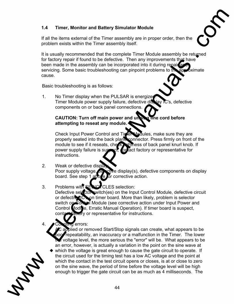
44
1.4 Timer, Monitor and Battery Simulator Module
If all the items external of the Timer assembly are in proper order, then the problem exists within the Timer assembly itself.
It is usually recommended that the complete Timer Module assembly be returned for factory repair if found to be defective. Then any improvements that have been made in the assembly can be incorporated into it during repair and servicing. Some basic troubleshooting can pinpoint problems to the approximate cause.
Basic troubleshooting is as follows: 1. No Timer display when the PULSAR is energized: Timer Module power supply failure, defective display IC's, defective
components on or back panel connections. CAUTION: Turn off main power and unplug line cord before
attempting to reseat any module. Check Input Power Control and Timer Modules, make sure they are
properly seated into the back plane connector. Press firmly on front of the module to see if it reseats, check tightness of back panel knurl knob. If power supply failure is suspect, contact factory or representative for instructions.
2. Weak or defective display: Poor supply voltage, defective display(s), defective components on display
board. See step 1 above for corrective action. 3. Problems with SEC/CYCLES selection: Defective selector switch(es) on the Input Control Module, defective circuit
or defective IC's on timer board. More than likely, problem is selector switch on Control Module (see corrective action under Input Power and Control Module, Erratic Manual Operation). If timer board is suspect, contact factory or representative for instructions.
4. Counting errors: AC applied or removed Start/Stop signals can create, what appears to be
poor repeatability, an inaccuracy or a malfunction in the Timer. The lower the voltage level, the more serious the "error" will be. What appears to be an error, however, is actually a variation in the point on the sine wave at which the voltage is great enough to cause the gate circuit to operate. If the circuit used for the timing test has a low AC voltage and the point at which the contact in the test circuit opens or closes, is at or close to zero on the sine wave, the period of time before the voltage level will be high enough to trigger the gate circuit can be as much as 4 milliseconds. The
www . El
ectric
alPar
tMan
uals
. com

45
total timing variation can be as much as 8 milliseconds. The shorter the duration of the timing test, the more significant the variation becomes. Therefore, if small timing variations would present a problem, it is recommended that an AC voltage of 115 volts or above or a DC voltage be used for voltage applied/removed test selections.
When the PULSAR Timer calibration is being tested, the AC voltage
variable is often overlooked. This is particularly true when the Timer is compared to a counter and the two are triggered simultaneously with an electronic switch. For best results, a DC voltage should be used to eliminate the variable. If testing the AC voltage Start/Stop characteristics is desired, then the Start/Stop signal must be triggered at the same point on the sine wave to assure that the gate signal will be repeatable. Ideally, the signal should be at a point near peak in the positive direction. In addition, the specified rms AC voltage values for the various Start/Stop control selections must be adhered to.
Another source of apparent "error" can be the programmable de-bounce
feature. If using electro-mechanical contacts for starting and stopping the Timer, and if those contacts have a tendency to bounce, there could be a difference between an external standard timer and the PULSAR Timer, depending on the programmed de-bounce period. To determine the programmed value, use a computer to perform a Timer Query (see Command Set for instructions).
If a timing error or variation persists after all the suspected causes of error
have been eliminated, then it is fairly certain the Timer is malfunctioning. Contact factory for return instructions.
5. Removal of Timer Module To remove the module from the chassis, A. Disconnect the power cord from the unit. B. Carefully remove the screws located in the front-bottom of the
module. C. Remove the knurl knob retaining screw located on the back panel. D. Hold the front the Module with one hand and gently, yet firmly,
press forward with the other hand on the back fan outlet port. Slide the module forward until you can grasp it with both hands from the front. Carefully remove the module from the chassis.
www . El
ectric
alPar
tMan
uals
. com

46
1.5 Voltage Amplifier Module
It is usually recommended that the complete Voltage Amplifier Module assembly be returned for factory repair if found to be defective. Then any improvements that have been made in the assembly can be incorporated into it during repair and servicing. Due to the extensive use of Surface Mount Technology in the amplifier module, there is very little that can be repaired without special tools and training. Some basic troubleshooting can pinpoint problems to the approximate cause.
Basic troubleshooting is as follows: 1. No Voltage Module display when the PULSAR is energized: Voltage Amplifier Module power supply failure, defective display IC's,
defective components on or back panel connections. CAUTION: Turn off main power and unplug line cord before
attempting to reseat any module. Check Input Power Control and Voltage Amplifier Modules, make sure
they are properly seated into the back plane connector. Press firmly on front of the module to see if it reseats, check tightness of back panel knurl knob. If power supply failure is suspect, contact factory or representative for instructions.
2. Weak or defective display: Poor supply voltage, defective display(s), defective components on display
board. See step 1 above for corrective action. 3. DC voltage output with amplifier turned off: It is normal to have a few millivolts of dc voltage with the output switched
off, since the amplifier is dc coupled. However, if the power supply starts to fail, the operator may measure 10's of volts dc across the output binding post. This is an indication that the power supply has a problem and needs to be replaced. Contact factory for return instructions.
4. Removal of Voltage Amplifier Module To remove the module from the chassis, A. Disconnect the power cord from the unit. B. Carefully remove the screws located in the front-bottom of the
module. C. Remove the knurl knob retaining screw located on the back panel. D. Hold the front the Module with one hand and gently, yet firmly,
press forward with the other hand on the back fan outlet port. Slide the module forward until you can grasp it with both hands from the front. Carefully remove the module from the chassis.
www . El
ectric
alPar
tMan
uals
. com

47
1.6 Current Amplifier Module
It is usually recommended that the complete Current Amplifier Module assembly be returned for factory repair if found to be defective. Then any improvements that have been made in the assembly can be incorporated into it during repair and servicing. Due to the extensive use of Surface Mount Technology in the amplifier module, there is very little that can be repaired without special tools and training. Some basic troubleshooting can pinpoint problems to the approximate cause.
Basic troubleshooting is as follows: NOTE: 1. No Current Module display when the PULSAR is energized: Current Amplifier Module power supply failure, defective display IC's,
defective components on or back panel connections. CAUTION: Turn off main power and unplug line cord before
attempting to reseat any module. Check Input Power Control and Current Amplifier Modules, make sure they are properly seated into the back plane connector. Press firmly on front of the module to see if it reseats, check tightness of back panel knurl knob. If power supply failure is suspect, contact factory or representative for instructions.
2. Weak or defective display: Poor supply voltage, defective display(s), defective components on display
board. See step 1 above for corrective action. 3. Removal of Current Amplifier Module To remove the module from the chassis, A. Disconnect the power cord from the unit. B. Carefully remove the screws located in the front-bottom of the
module. C. Remove the knurl knob retaining screw located on the back panel. D. Hold the front the Module with one hand and gently, yet firmly,
press forward with the other hand on the back fan outlet port. Slide the module forward until you can grasp it with both hands from the front. Carefully remove the module from the chassis.
www . El
ectric
alPar
tMan
uals
. com

48
II. Testing Procedures
Testing of Westinghouse Type AR Relay AVO Multi-Amp PULSAR Date: September 30, 1993 Rev: B IEEE Device Number: 94 Function: Auxiliary This relay test sheet describes the use of the AVO Multi-Amp PULSAR test instrument to perform the AR's protective relay acceptance tests. Test connections to the AVO Multi-Amp PULSAR relay test set and manufacturer recommended relay settings are included. References: Manufacturer's Reference I.L. 41-759 Literature Test Equipment PULSAR Operating Manual Instructional Material Description of Relay The AR relay is a high-speed auxiliary relay used in breaker-failure protection schemes to initiate a breaker-lockout device to restrict energizing of a circuit breaker once a fault has occurred. PRECAUTIONS ***************WARNING************** Dangerous and potentially fatal voltage can be developed across the output terminals of the PULSAR relay test set, refer to the PULSAR operation manual for further instructions. Always turn the outputs OFF before connecting, removing or touching any output terminal or test lead, use extreme caution when turning on or using the PULSAR relay test set. ALWAYS TEST THIS RELAY IN ITS CASE.
www . El
ectric
alPar
tMan
uals
. com
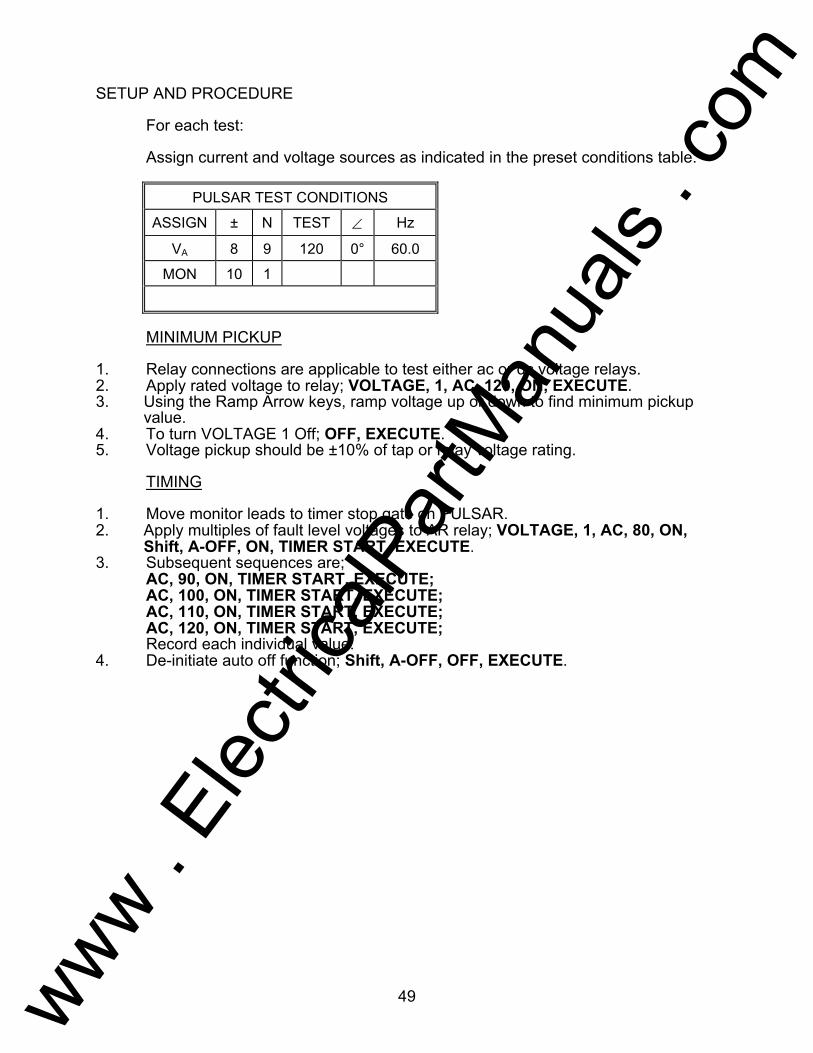
49
SETUP AND PROCEDURE For each test: Assign current and voltage sources as indicated in the preset conditions table.
PULSAR TEST CONDITIONS
ASSIGN ± N TEST ∠ Hz
VA 8 9 120 0° 60.0
MON 10 1
MINIMUM PICKUP 1. Relay connections are applicable to test either ac or dc voltage relays. 2. Apply rated voltage to relay; VOLTAGE, 1, AC, 120, ON, EXECUTE. 3. Using the Ramp Arrow keys, ramp voltage up or down to find minimum pickup
value. 4. To turn VOLTAGE 1 Off; OFF, EXECUTE. 5. Voltage pickup should be ±10% of tap or relay voltage rating. TIMING 1. Move monitor leads to timer stop gate on PULSAR. 2. Apply multiples of fault level voltages to AR relay; VOLTAGE, 1, AC, 80, ON,
Shift, A-OFF, ON, TIMER START, EXECUTE. 3. Subsequent sequences are; AC, 90, ON, TIMER START, EXECUTE; AC, 100, ON, TIMER START, EXECUTE; AC, 110, ON, TIMER START, EXECUTE; AC, 120, ON, TIMER START, EXECUTE; Record each individual value. 4. De-initiate auto off function; Shift, A-OFF, OFF, EXECUTE.
www . El
ectric
alPar
tMan
uals
. com
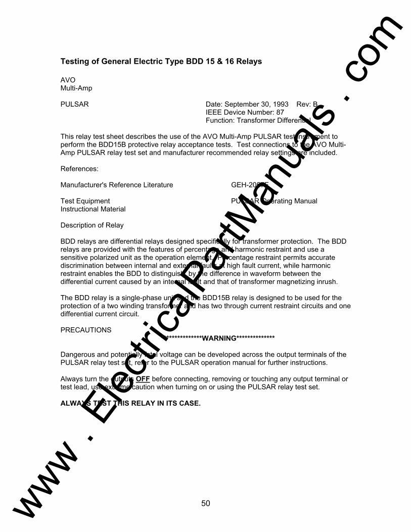
50
Testing of General Electric Type BDD 15 & 16 Relays AVO Multi-Amp PULSAR Date: September 30, 1993 Rev: B IEEE Device Number: 87 Function: Transformer Differential This relay test sheet describes the use of the AVO Multi-Amp PULSAR test instrument to perform the BDD15B protective relay acceptance tests. Test connections to the AVO Multi-Amp PULSAR relay test set and manufacturer recommended relay settings are included. References: Manufacturer's Reference Literature GEH-2057F Test Equipment PULSAR Operating Manual Instructional Material Description of Relay BDD relays are differential relays designed specifically for transformer protection. The BDD relays are provided with the features of percentage and harmonic restraint and use a sensitive polarized unit as the operation element. Percentage restraint permits accurate discrimination between internal and external faults at high fault current, while harmonic restraint enables the BDD to distinguish, by the difference in waveform between the differential current caused by an internal fault and that of transformer magnetizing inrush. The BDD relay is a single-phase unit and the BDD15B relay is designed to be used for the protection of a two winding transformer and has two through current restraint circuits and one differential current circuit. PRECAUTIONS ***************WARNING************** Dangerous and potentially fatal voltage can be developed across the output terminals of the PULSAR relay test set, refer to the PULSAR operation manual for further instructions. Always turn the outputs OFF before connecting, removing or touching any output terminal or test lead, use extreme caution when turning on or using the PULSAR relay test set. ALWAYS TEST THIS RELAY IN ITS CASE.
www . El
ectric
alPar
tMan
uals
. com

51
SETUP AND PROCEDURE For each test: Assign current and voltage sources as indicated in the preset conditions
table. The test values are based upon a 5A tap and 25% slope relay setting.
The dc auxiliary is supplied either using the station dc battery supply or
the PULSAR Battery Simulator. The dc terminals to connect are 1 (+) and 7 (-). These settings assume usage of the 125 V version.
PULSAR TEST CONDITIONS
ASSIGN CONNECT TEST VALUES HZ
± N ∠
IA 6 5 IA 1.2 0° 60.0
IB 4 5 IB 1.2 0° 60.0
MON 1 2
MINIMUM PICKUP 1. Set PULSAR current channels equal to (tap * 0.3) value; CURRENT, 1, 2,
AC, 1.2, EXECUTE. 2. Turn current (IA) ON; CURRENT, 1, AC, ON, EXECUTE. Using RAMP
Arrow keys, ramp current channel up or down to find minimum pickup. Turn IA off; CURRENT, 1, OFF, EXECUTE. Repeat test for current (IB), all commands for IB are CURRENT 2.
3. Minimum pickup should be within ±10% of (tap * 0.3) value. Refer to relay instruction manual for adjustment to minimum pickup resistor.
www . El
ectric
alPar
tMan
uals
. com

52
PULSAR TEST CONDITIONS
ASSIGN CONNECT TEST VALUES HZ
± N ∠
IA 6 4 IA 25 0° 60.0
MON 1 2
THROUGH CURRENT RESTRAINT 1. Set PULSAR current channel (IA) equal to 25 amperes; CURRENT, 1, AC,
25, EXECUTE. 2. Turn current (IA) ON; CURRENT, 1, ON, EXECUTE; BDD15B relay should
be in restraint, (relay's main trip contacts remain open rather than close). 3. Turn current OFF; OFF, EXECUTE. Disconnect relay and set up for
Harmonic restraint test.
PULSAR TEST CONDITIONS
ASSIGN CONNECT TEST VALUES HZ
± N ∠
IA 6 5 IA 4 0° 60.0
IB 6 5 IB 1 0° 120.0
MON 1 2
HARMONIC RESTRAINT using pure 2ndHarmonic Current 1. Set IA and IB on PULSAR to above parameters; CURRENT, 2, AC, 1,
FREQ, 120, Shift, RST.PH, CURRENT 1, AC, 4, EXECUTE. 2. Initiate PULSAR; CURRENT, 2, ON, CURRENT 1, AC, ON, EXECUTE.
Using the RAMP Arrow keys ramp IA up to find pickup of harmonic restraint trip contact. Record value.
3. De-initiate PULSAR; CURRENT, 1, 2, OFF, EXECUTE. 5. Calculate percent harmonic with the formula as referred to under Current
Sources-Harmonic Restraint Test.
www . El
ectric
alPar
tMan
uals
. com

53
PULSAR TEST CONDITIONS
ASSIGN CONNECT TEST VALUES HZ
± N ∠
IA 6 5 IA 4 0° 60.0
IB 6 5 IB 8.89 0° 60.0
MON 1 2
HARMONIC RESTRAINT using H_WAVE (Diode Test Method) 1. Set IA to above parameters; CURRENT, 1, AC, 4, EXECUTE. 2. Set IB to 8.89A, H_WAVE, to establish 4A Idc (as required for diode test
method), refer to section Current Sources-Harmonic Restraint Test; CURRENT, 2, AC, 8.89, Shift, H_WAVE, EXECUTE.
3. Initiate IA and IB; CURRENT, 2, ON, CURRENT, 1, AC, ON, EXECUTE. 4. Using the RAMP Arrow keys, ramp IA up to find pickup of harmonic
restraint trip contact. Record value. 5. De-initiate PULSAR; CURRENT, 1, 2, OFF, EXECUTE. 6. Restore to sine wave output; CURRENT, 0, Shift, SINE, EXECUTE. 7. Refer to the manufacturers instruction literature for the appropriate %
Harmonic Curve.
PULSAR TEST CONDITIONS
ASSIGN CONNECT TEST VALUES HZ
± N ∠
IA 6 5 IA 4 0° 60.0
IB 6 4 IB 20 0° 60.0
MON 1 2
SLOPE TEST 1. Set IA equal to 4 amperes and IB equal to 20 amperes; CURRENT, 1, AC
4, CURRENT, 2, AC, 20, EXECUTE. 2. Turn both IA and IB ON; CURRENT, 2, ON, CURRENT, 1, AC, ON,
EXECUTE. Using the RAMP Arrow keys ramp IA up until main trip
www . El
ectric
alPar
tMan
uals
. com
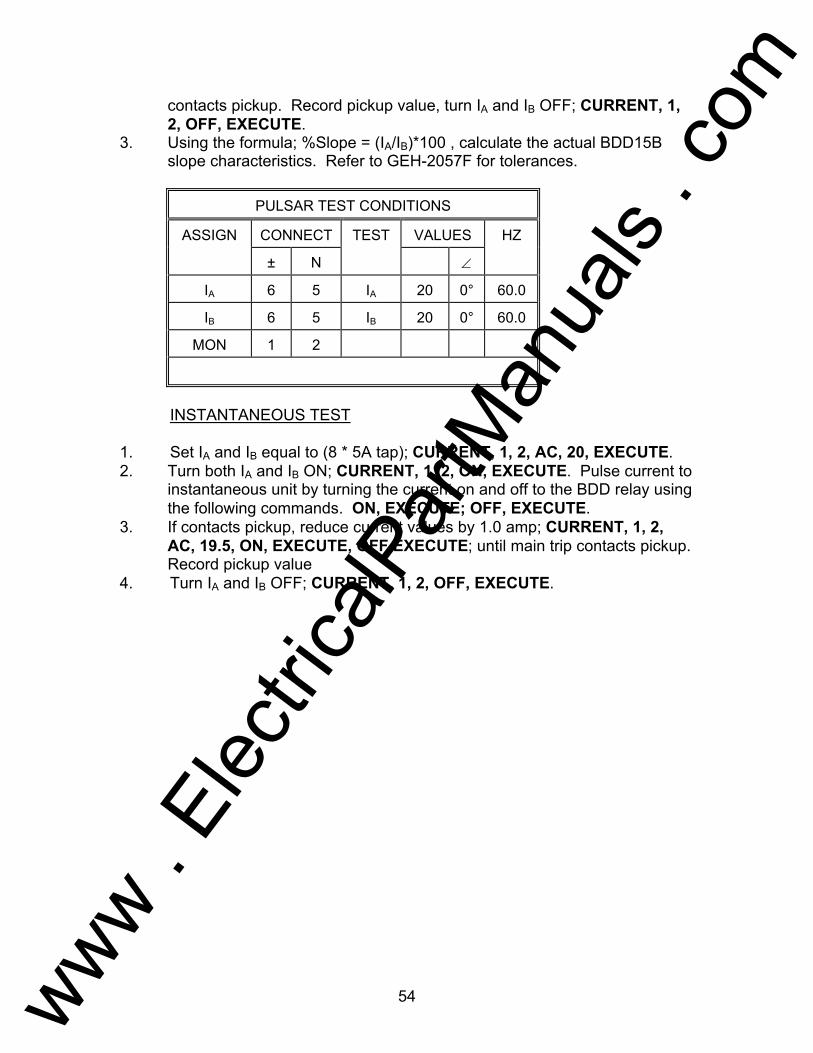
54
contacts pickup. Record pickup value, turn IA and IB OFF; CURRENT, 1, 2, OFF, EXECUTE.
3. Using the formula; %Slope = (IA/IB)*100 , calculate the actual BDD15B slope characteristics. Refer to GEH-2057F for tolerances.
PULSAR TEST CONDITIONS
ASSIGN CONNECT TEST VALUES HZ
± N ∠
IA 6 5 IA 20 0° 60.0
IB 6 5 IB 20 0° 60.0
MON 1 2
INSTANTANEOUS TEST 1. Set IA and IB equal to (8 * 5A tap); CURRENT, 1, 2, AC, 20, EXECUTE. 2. Turn both IA and IB ON; CURRENT, 1, 2, ON, EXECUTE. Pulse current to
instantaneous unit by turning the current on and off to the BDD relay using the following commands. ON, EXECUTE; OFF, EXECUTE.
3. If contacts pickup, reduce current values by 1.0 amp; CURRENT, 1, 2, AC, 19.5, ON, EXECUTE, OFF EXECUTE; until main trip contacts pickup. Record pickup value
4. Turn IA and IB OFF; CURRENT, 1, 2, OFF, EXECUTE.
www . El
ectric
alPar
tMan
uals
. com

55
AVO Multi-Amp PULSAR Date: September 30, 1993 Rev: B IEEE Device Number: 87 Function: Transformer Differential This relay test sheet describes the use of the AVO Multi-Amp PULSAR test instrument to perform the BDD16B protective relay acceptance tests. Test connections to the AVO Multi-Amp PULSAR relay test set and manufacturer recommended relay settings are included. References: Manufacturer's Reference GEH-2057F Literature Test Equipment PULSAR Operating Manual Instructional Material Description of Relay BDD relays are differential relays designed specifically for transformer protection. The BDD relays are provided with the features of percentage and harmonic restraint and use a sensitive polarized unit as the operation element. Percentage restraint permits accurate discrimination between internal and external faults at high fault current, while harmonic restraint enables the BDD to distinguish, by the difference in waveform between the differential current caused by an internal fault and that of transformer magnetizing inrush. The BDD relay is a single-phase unit and the BDD16B relay is designed to be used for the protection of a three winding transformer and has three through current restraint circuits and one differential current circuit. PRECAUTIONS ***************WARNING************** Dangerous and potentially fatal voltage can be developed across the output terminals of the PULSAR relay test set, refer to the PULSAR operation manual for further instructions. Always turn the outputs OFF before connecting, removing or touching any output terminal or test lead, use extreme caution when turning on or using the PULSAR relay test set. ALWAYS TEST THIS RELAY IN ITS CASE.
www . El
ectric
alPar
tMan
uals
. com

56
SETUP AND PROCEDURE For each test: Assign current and voltage sources as indicated in the preset conditions
table. The test values are based upon a 5A tap and 25% slope relay setting.
The dc auxiliary is supplied either using the station dc battery supply or
the PULSAR Battery Simulator. The dc terminals to connect are 1 (+) and 10 (-). These settings assume usage of the 125 V version.
PULSAR TEST CONDITIONS
ASSIGN CONNECT TEST VALUES HZ
± N ∠
IA 6 5 IA 1.2 0° 60.0
IB 4 5 IB 1.2 0° 60.0
IC 3 5 IC 1.2 0° 60.0
MON 1 2
MINIMUM PICKUP 1. Set PULSAR current channels equal to (tap * 0.3) value; CURRENT, 0,
AC, 1.2, EXECUTE. 2. Turn current (IA) ON; CURRENT, 1, AC, ON, EXECUTE. Using RAMP
Arrow keys, ramp current channel up or down to find minimum pickup. Turn IA OFF; CURRENT, 1, OFF, EXECUTE. Repeat test for current (IB and IC), all commands for IB are CURRENT, 2 and IC are CURRENT, 3.
3. Minimum pickup should be within ±10% of (tap * 0.3) value. Refer to relay instruction manual for adjustment to minimum pickup resistor.
www . El
ectric
alPar
tMan
uals
. com
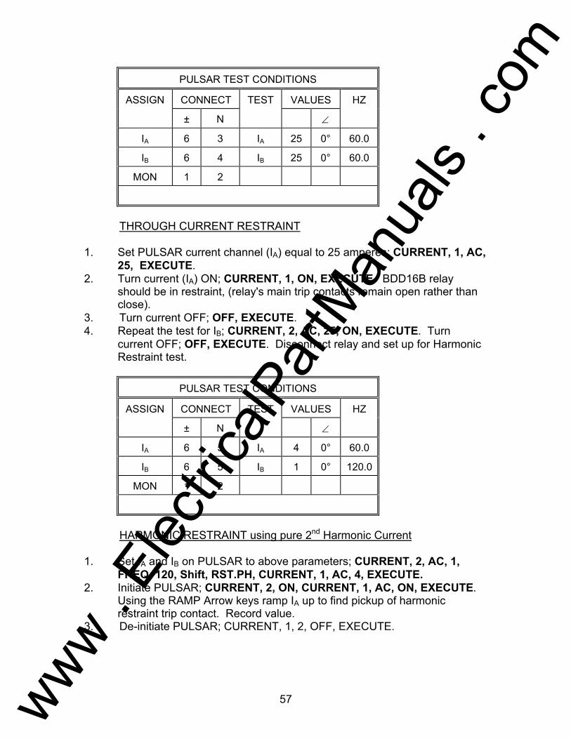
57
PULSAR TEST CONDITIONS
ASSIGN CONNECT TEST VALUES HZ
± N ∠
IA 6 3 IA 25 0° 60.0
IB 6 4 IB 25 0° 60.0
MON 1 2
THROUGH CURRENT RESTRAINT 1. Set PULSAR current channel (IA) equal to 25 amperes; CURRENT, 1, AC,
25, EXECUTE. 2. Turn current (IA) ON; CURRENT, 1, ON, EXECUTE. BDD16B relay
should be in restraint, (relay's main trip contacts remain open rather than close).
3. Turn current OFF; OFF, EXECUTE. 4. Repeat the test for IB; CURRENT, 2, AC, 25, ON, EXECUTE. Turn
current OFF; OFF, EXECUTE. Disconnect relay and set up for Harmonic Restraint test.
PULSAR TEST CONDITIONS
ASSIGN CONNECT TEST VALUES HZ
± N ∠
IA 6 5 IA 4 0° 60.0
IB 6 5 IB 1 0° 120.0
MON 1 2
HARMONIC RESTRAINT using pure 2nd Harmonic Current 1. Set IA and IB on PULSAR to above parameters; CURRENT, 2, AC, 1,
FREQ, 120, Shift, RST.PH, CURRENT, 1, AC, 4, EXECUTE. 2. Initiate PULSAR; CURRENT, 2, ON, CURRENT, 1, AC, ON, EXECUTE.
Using the RAMP Arrow keys ramp IA up to find pickup of harmonic restraint trip contact. Record value.
3. De-initiate PULSAR; CURRENT, 1, 2, OFF, EXECUTE.
www . El
ectric
alPar
tMan
uals
. com

58
4. Calculate percent harmonic with the formula as referred to under Current
Sources-Harmonic Restraint Test.
PULSAR TEST CONDITIONS
ASSIGN CONNECT TEST VALUES HZ
± N ∠
IA 6 5 IA 4 0° 60.0
IB 6 5 IB 8.89 0° 60.0
MON 1 2
HARMONIC RESTRAINT using H_WAVE (Diode Test Method) 1. Set IA to above parameters; CURRENT, 1, AC, 4, EXECUTE. 2. Set IB to 8.89A, H_WAVE, to establish 4A Idc (as required for diode test
method), refer to section Current Sources-Harmonic Restraint Test; CURRENT, 2, AC, 8.89, Shift, H_WAVE, EXECUTE.
3. Initiate IA and IB; CURRENT, 2, ON, CURRENT, 1, AC, ON, EXECUTE. 4. Using the RAMP Arrow keys, ramp IA up to find pickup of harmonic
restraint trip contact. Record value. 5. De-initiate PULSAR; CURRENT, 1, 2, OFF, EXECUTE. 6. Restore sine wave output; CURRENT, 0, Shift, SINE, EXECUTE. 7. Refer to the manufacturers instruction literature for the appropriate %
Harmonic Curve.5
PULSAR TEST CONDITIONS
ASSIGN CONNECT TEST VALUES HZ
± N ∠
IA 6 5 IA 4 0° 60.0
IB 6 4 IB 20 0° 60.0
IC 4 3 IC 20 0° 60.0
MON 1 2
www . El
ectric
alPar
tMan
uals
. com

59
SLOPE TEST 1. Set IA equal to 4 amperes and IB equal to 20 amperes; CURRENT, 1, AC
4, CURRENT, 2, AC, 20, EXECUTE. 2. Turn both IA and IB ON; CURRENT, 2, ON, CURRENT, 1, AC, ON,
EXECUTE. Using the RAMP Arrow keys ramp IA up until main trip contacts pickup. Record pickup value, turn IA and IB OFF; CURRENT, 1, 2, OFF, EXECUTE.
3. Using the formula; % Slope = (IA/IB)*100 , calculate the actual BDD16B slope characteristics. Refer to GEH-2057F for tolerances.
4. Repeat the test for IA and IC.
PULSAR TEST CONDITIONS
ASSIGN CONNECT TEST VALUES HZ
± N ∠
IA 6 5 IA 20.0 0° 60.0
IB 6 5 IB 20.0 0° 60.0
MON 1 2
INSTANTANEOUS TEST 1. Set IA and IB equal to (8 * 5A tap); CURRENT, 1, 2, AC, 20, EXECUTE. 2. Turn both IA and IB ON; CURRENT, 1, 2, ON, EXECUTE. Pulse current to
instantaneous unit by turning the current on and off to the BDD relay using the following commands. ON, EXECUTE; OFF, EXECUTE.
3. If contacts pickup, reduce current values by 1.0 amp; CURRENT, 1, 2, AC, 19.5, ON, EXECUTE, OFF EXECUTE; until main trip contacts pickup. Record pickup value
4. Turn IA and IB OFF; CURRENT, 1, 2, OFF, EXECUTE.
www . El
ectric
alPar
tMan
uals
. com

60
Testing of Basler Type BE1-81 O/U Relay
AVO Multi-Amp PULSAR Date: September 30, 1993 Rev: B IEEE Device Number: 81 Function: Frequency Relay This relay test sheet describes the use of the AVO Multi-Amp PULSAR test instrument to perform the BE1-81 O/U protective relay acceptance tests. Test connections to the AVO Multi-Amp PULSAR relay test set and manufacturer recommended relay settings are included. References: Manufacturer's Reference I.L. 41-501.2F Literature Test Equipment PULSAR Operating Manual Instructional Material Description of Relay The BE1-81 O/U is a single phase solid-state relay used in protection schemes against the effects of overfrequency or underfrequency. PRECAUTIONS ***************WARNING************** Dangerous and potentially fatal voltage can be developed across the output terminals of the PULSAR relay test set, refer to the PULSAR operation manual for further instructions. Always turn the outputs OFF before connecting, removing or touching any output terminal or test lead, use extreme caution when turning on or using the PULSAR relay test set. ALWAYS TEST THIS RELAY IN ITS CASE.
www . El
ectric
alPar
tMan
uals
. com

61
Relay Notes:
www . El
ectric
alPar
tMan
uals
. com
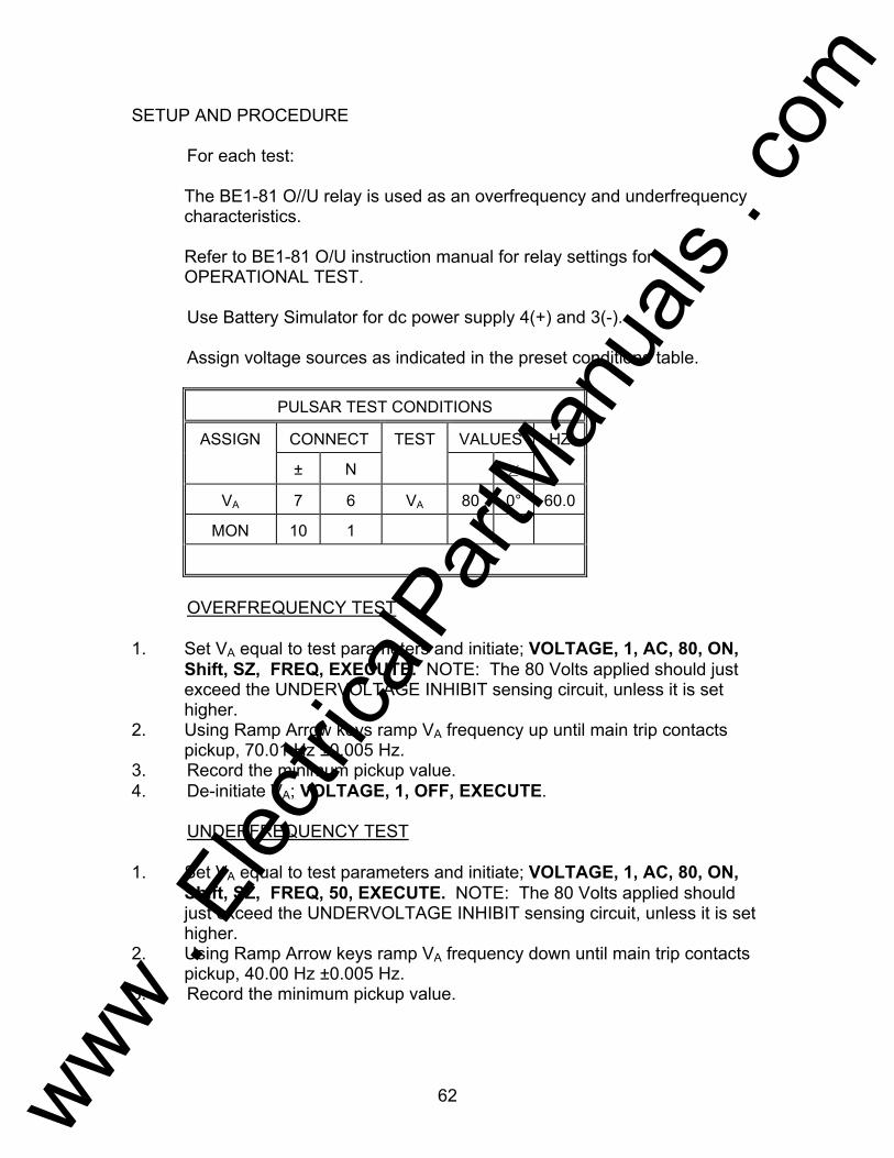
62
SETUP AND PROCEDURE For each test: The BE1-81 O//U relay is used as an overfrequency and underfrequency
characteristics. Refer to BE1-81 O/U instruction manual for relay settings for
OPERATIONAL TEST. Use Battery Simulator for dc power supply 4(+) and 3(-). Assign voltage sources as indicated in the preset conditions table.
PULSAR TEST CONDITIONS
ASSIGN CONNECT TEST VALUES HZ
± N ∠
VA 7 6 VA 80 0° 60.0
MON 10 1
OVERFREQUENCY TEST 1. Set VA equal to test parameters and initiate; VOLTAGE, 1, AC, 80, ON,
Shift, SZ, FREQ, EXECUTE. NOTE: The 80 Volts applied should just exceed the UNDERVOLTAGE INHIBIT sensing circuit, unless it is set higher.
2. Using Ramp Arrow keys ramp VA frequency up until main trip contacts pickup, 70.01 Hz ±0.005 Hz.
3. Record the minimum pickup value. 4. De-initiate VA; VOLTAGE, 1, OFF, EXECUTE. UNDERFREQUENCY TEST 1. Set VA equal to test parameters and initiate; VOLTAGE, 1, AC, 80, ON,
Shift, SZ, FREQ, 50, EXECUTE. NOTE: The 80 Volts applied should just exceed the UNDERVOLTAGE INHIBIT sensing circuit, unless it is set higher.
2. Using Ramp Arrow keys ramp VA frequency down until main trip contacts pickup, 40.00 Hz ±0.005 Hz.
3. Record the minimum pickup value.
www . El
ectric
alPar
tMan
uals
. com

63
4. De-initiate VA; VOLTAGE, 1, OFF, EXECUTE. FREQUENCY SELECTOR TEST 1. Set VA equal to frequency test parameters and initiate; VOLTAGE, 1, AC,
80, ON, Shift, SZ, FREQ, 50, EXECUTE. NOTE: The 80 Volts applied should just exceed the UNDERVOLTAGE INHIBIT sensing circuit, unless it is set higher.
2. Using Ramp Arrow keys ramp VA frequency up until main trip contacts pickup, 51.11 Hz ±0.005 Hz.
3. Record the minimum pickup value. 4. Repeat steps 1 and 2 for BE1-81 settings of 52.22 Hz, 54.44 Hz, and
58.88 Hz. 5. De-initiate VA; VOLTAGE, 1, OFF, EXECUTE. TIMING TEST 1. Set VA to normal voltage and frequency; VOLTAGE, 1, AC, 115, FREQ,
60, ON, Shift, RST. PH, SZ, EXECUTE. 2. Move monitor circuit to timer stop gate. (Terminal 2). 3. Set VA equal to fault voltage and fault frequency 53 Hz; VOLTAGE, 1, AC,
80, FREQ, 53, Shift, A-OFF, ON, TIMER START, EXECUTE. 4. When the relay trips, it will turn off the output and stop the Timer. Record
the pickup value. Repeat testing sequence for any additional fault values. If timing type E1 (definite time delay), use formula:
If timing type D1 (inverse time delay), use formula:
Depending on the timing type formula used, the PULSAR timer should equal the Time delay calculated for the BE1-81 .
5. To reset PULSAR to original default settings press RESET button on Input Power and Control Module.
delaycycles
frequencyTime = 11
input
delay point
cycles
frequencyTime =Plot + 3
Input
www . El
ectric
alPar
tMan
uals
. com

64
Testing of General Electric Type CEB Relay AVO Multi-Amp PULSAR Date: September 30, 1993 Rev: A IEEE Device Number: 21 Function: Distance Relay This relay test sheet describes the use of the AVO Multi-Amp PULSAR test instrument to perform the CEB12B protective relay acceptance tests. Test connections to the AVO Multi-Amp PULSAR relay test set and manufacturer recommended relay settings are included. References: Manufacturer's Reference Literature GEK-26240 Test Equipment PULSAR Operating Manual Instructional Material Description of Relay The CEB12 and CEB51 relays are single-phase, single zone, mho distance relay with provisions for offsetting the characteristic. The relays are designed primarily for use where one zone of back-up protection is required. Probably the most common application of the CEB relays is in generator back-up protection schemes where the relays are used to protect the generator from faults on the adjacent system which are not cleared by the first line relays. PRECAUTIONS ***************WARNING************** Dangerous and potentially fatal voltage can be developed across the output terminals of the PULSAR relay test set, refer to the PULSAR operation manual for further instructions. Always turn the outputs OFF before connecting, removing or touching any output terminal or test lead, use extreme caution when turning on or using the PULSAR relay test set. ALWAYS TEST THIS RELAY IN ITS CASE.
www . El
ectric
alPar
tMan
uals
. com
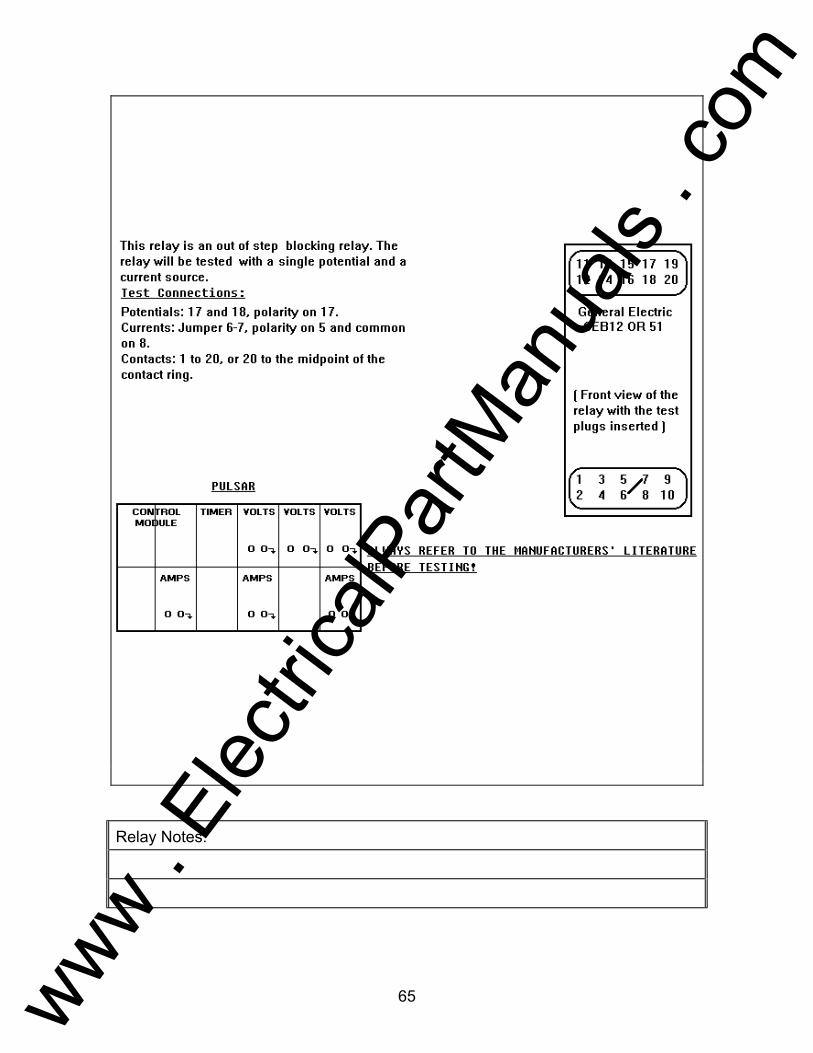
65
Relay Notes:
www . El
ectric
alPar
tMan
uals
. com

66
SETUP AND PROCEDURE For each test: Assign current and voltage sources as indicated in the preset conditions
table. Execute the test as defined in the PULSAR CONDITIONS table. Jumper relay terminals 6 to 7. All test values are based upon a 60° maximum torque angle, 5Ω Reach,
and the following formula:
PULSAR TEST CONDITIONS
ASSIGN CONNECT TEST VALUES HZ
± N ∠
VA 17 18 VA 55 0° 60.0
IA 5 8 IA 5 60° 60.0
MON 1 20
* = Value depends on offset tap
ALWAYS REFER TO THE MANUFACTURERS' LITERATURE BEFORE TESTING! REACH TEST 1. Connect the Monitor circuit to the appropriate relay contacts. 2. Set IA to 5A and 60°, set VA to 55v and 0°, using the following keystrokes;
CURRENT, 1, AC, 5, PHASE, 60 , VOLTAGE, 1, AC, 55, EXECUTE. 3. Initiate PULSAR; CURRENT, 1, ON, VOLTAGE, 1, ON, EXECUTE. Using
the appropriate Ramp Arrow keys ,, ramp VA until the contacts pickup. 4. Record the pickup value,refer to the CEB51 I.L. for any adjustment. 5. Turn IA and VA, OFF whenever an adjustment is required or the test is
completed. CURRENT, 1, VOLTAGE, 1, OFF, EXECUTE.
Z = V
2xI
www . El
ectric
alPar
tMan
uals
. com
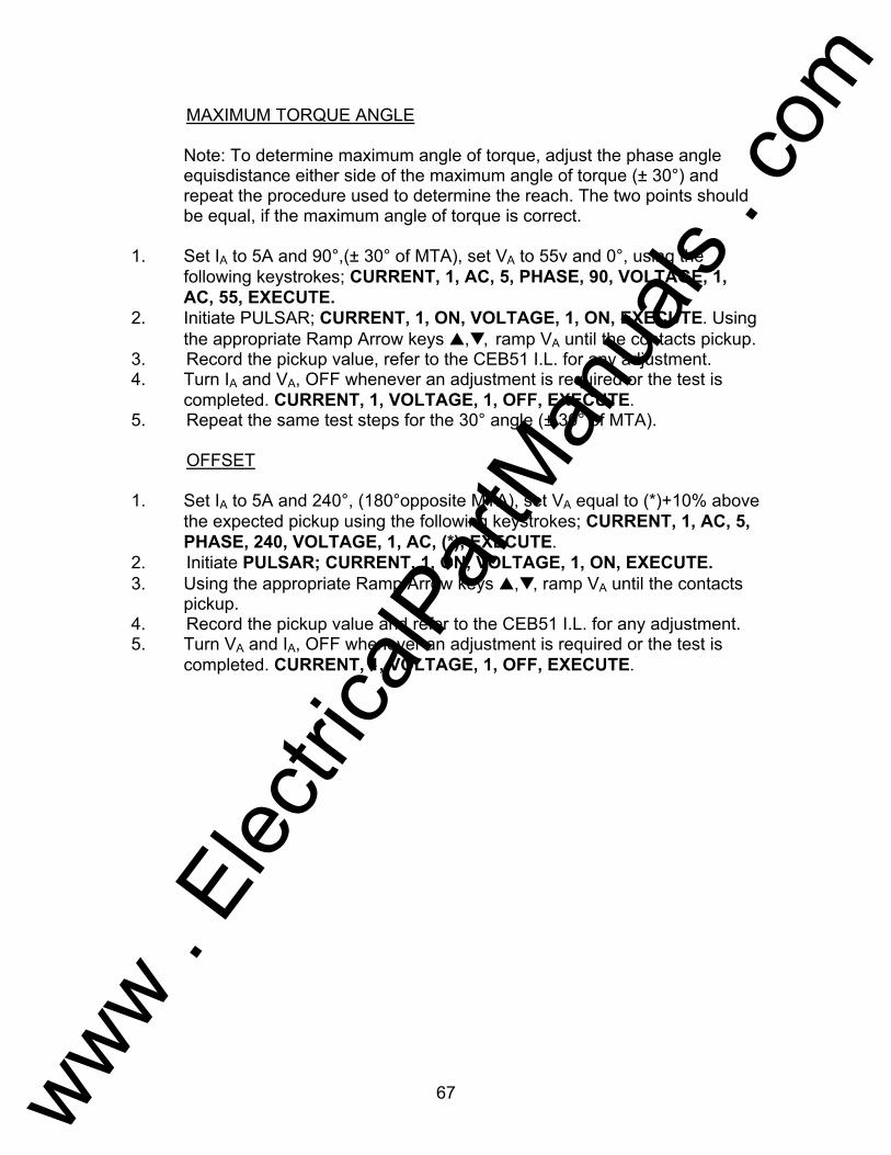
67
MAXIMUM TORQUE ANGLE Note: To determine maximum angle of torque, adjust the phase angle
equisdistance either side of the maximum angle of torque (± 30°) and repeat the procedure used to determine the reach. The two points should be equal, if the maximum angle of torque is correct.
1. Set IA to 5A and 90°,(± 30° of MTA), set VA to 55v and 0°, using the
following keystrokes; CURRENT, 1, AC, 5, PHASE, 90, VOLTAGE, 1, AC, 55, EXECUTE.
2. Initiate PULSAR; CURRENT, 1, ON, VOLTAGE, 1, ON, EXECUTE. Using the appropriate Ramp Arrow keys ,, ramp VA until the contacts pickup.
3. Record the pickup value, refer to the CEB51 I.L. for any adjustment. 4. Turn IA and VA, OFF whenever an adjustment is required or the test is
completed. CURRENT, 1, VOLTAGE, 1, OFF, EXECUTE. 5. Repeat the same test steps for the 30° angle (± 30° of MTA). OFFSET 1. Set IA to 5A and 240°, (180°opposite MTA), set VA equal to (*)+10% above
the expected pickup using the following keystrokes; CURRENT, 1, AC, 5, PHASE, 240, VOLTAGE, 1, AC, (*), EXECUTE.
2. Initiate PULSAR; CURRENT, 1, ON, VOLTAGE, 1, ON, EXECUTE. 3. Using the appropriate Ramp Arrow keys ,, ramp VA until the contacts
pickup. 4. Record the pickup value and refer to the CEB51 I.L. for any adjustment. 5. Turn VA and IA, OFF whenever an adjustment is required or the test is
completed. CURRENT, 1, VOLTAGE, 1, OFF, EXECUTE.
www . El
ectric
alPar
tMan
uals
. com

68
Testing of General Electric Type CEY Relay AVO Multi-Amp PULSAR Date: September 30, 1993 Rev: A IEEE Device Number: 21 Function: Distance Relay This relay test sheet describes the use of the AVO Multi-Amp PULSAR test instrument to perform the CEY51A or CEY51B protective relay acceptance tests. Test connections to the AVO Multi-Amp PULSAR relay test set and manufacturer recommended relay settings are included. References: Manufacturer's Reference GEK-1265 Literature Test Equipment PULSAR Operating Manual Instructional Material Description of Relay The CEY51A and CEY51B relays are three-phase, high speed, single zone, mho distance relay with provisions for offsetting the characteristic. The relays are designed primarily for use where one zone of back-up protection is required. Probably the most common application of the CEY relays is in generator back-up protection schemes where the relays are used to protect the generator from faults on the adjacent system which are not cleared by the first line relays. PRECAUTIONS ***************WARNING************** Dangerous and potentially fatal voltage can be developed across the output terminals of the PULSAR relay test set, refer to the PULSAR operation manual for further instructions. Always turn the outputs OFF before connecting, removing or touching any output terminal or test lead, use extreme caution when turning on or using the PULSAR relay test set. ALWAYS TEST THIS RELAY IN ITS CASE.
www . El
ectric
alPar
tMan
uals
. com

69
Relay Notes:
www . El
ectric
alPar
tMan
uals
. com

70
SETUP AND PROCEDURE For each test: Assign current and voltage sources as indicated in the preset conditions
table. Execute the test as defined in the PULSAR CONDITIONS table. Jumper relay terminals 6 to 8 to 10, 13 to 16 to 17, and 18 to 19 to 20. All test values are based upon a 60° maximum torque angle, 5 Ω Reach,
and the following formula:
PULSAR TEST CONDITIONS
ASSIGN CONNECT TEST VALUES HZ
± N ∠
VA 15 17 VA 55 0° 60.0
IA 5 7 IA 5 60° 60.0
MON 1 11
* = Value depends on offset tap
ALWAYS REFER TO THE MANUFACTURERS' LITERATURE BEFORE TESTING! REACH TEST 0/ 1-2 1. Connect the Monitor circuit to the appropriate relay contacts. 2. Set IA to 5A and 60°, set VA to 55v and 0°, using the following keystrokes;
CURRENT, 1, AC, 5, PHASE, 60 , VOLTAGE, 1, AC, 55, EXECUTE. 3. Initiate PULSAR; CURRENT, 1, ON, VOLTAGE, 1, ON, EXECUTE. Using
the appropriate Ramp Arrow keys ,, ramp VA until the contacts pickup. 4. Record the pickup value,refer to the CEY51 I.L. for any adjustment. 5. Turn IA and VA, OFF whenever an adjustment is required or the test is
completed. CURRENT, 1, VOLTAGE, 1, OFF, EXECUTE.
Z = V
2xI
www . El
ectric
alPar
tMan
uals
. com
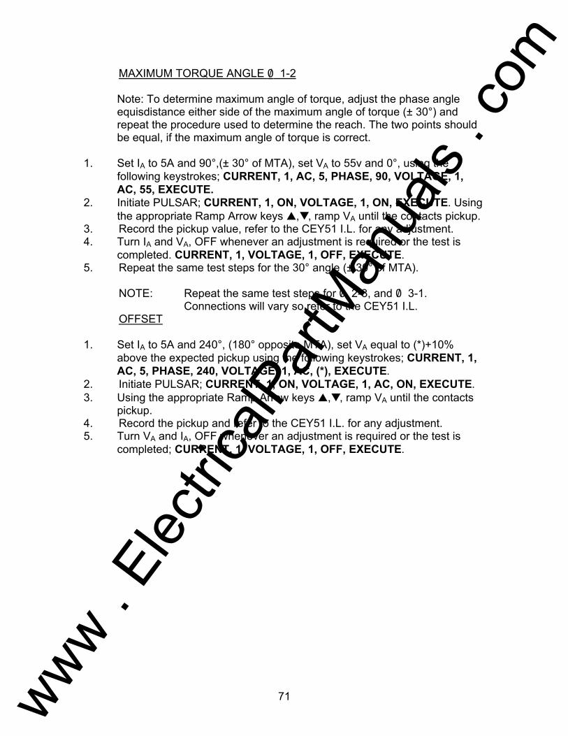
71
MAXIMUM TORQUE ANGLE 0/ 1-2 Note: To determine maximum angle of torque, adjust the phase angle
equisdistance either side of the maximum angle of torque (± 30°) and repeat the procedure used to determine the reach. The two points should be equal, if the maximum angle of torque is correct.
1. Set IA to 5A and 90°,(± 30° of MTA), set VA to 55v and 0°, using the
following keystrokes; CURRENT, 1, AC, 5, PHASE, 90, VOLTAGE, 1, AC, 55, EXECUTE.
2. Initiate PULSAR; CURRENT, 1, ON, VOLTAGE, 1, ON, EXECUTE. Using the appropriate Ramp Arrow keys ,, ramp VA until the contacts pickup.
3. Record the pickup value, refer to the CEY51 I.L. for any adjustment. 4. Turn IA and VA, OFF whenever an adjustment is required or the test is
completed. CURRENT, 1, VOLTAGE, 1, OFF, EXECUTE. 5. Repeat the same test steps for the 30° angle (± 30° of MTA). NOTE: Repeat the same test steps for 0/ 2-3, and 0/ 3-1.
Connections will vary so refer to the CEY51 I.L. OFFSET 1. Set IA to 5A and 240°, (180° opposite MTA), set VA equal to (*)+10%
above the expected pickup using the following keystrokes; CURRENT, 1, AC, 5, PHASE, 240, VOLTAGE, 1, AC, (*), EXECUTE.
2. Initiate PULSAR; CURRENT, 1, ON, VOLTAGE, 1, AC, ON, EXECUTE. 3. Using the appropriate Ramp Arrow keys ,, ramp VA until the contacts
pickup. 4. Record the pickup and refer to the CEY51 I.L. for any adjustment. 5. Turn VA and IA, OFF whenever an adjustment is required or the test is
completed; CURRENT, 1, VOLTAGE, 1, OFF, EXECUTE.
www . El
ectric
alPar
tMan
uals
. com
72
Testing of Westinghouse Type CF-1 Relay
AVO Multi-Amp PULSAR Date: September 30, 1993 Rev: B IEEE Device Number: 81 Function: Frequency Relay This relay test sheet describes the use of the AVO Multi-Amp PULSAR test instrument to perform the CF-1 protective relay acceptance tests. Test connections to the AVO Multi-Amp PULSAR relay test set and manufacturer recommended relay settings are included. References: Manufacturer's Reference I.L. 41-501.2F Literature Test Equipment PULSAR Operating Manual Instructional Material Description of Relay The CF-1 is a single phase induction disk relay used in protection schemes against the effects of overfrequency or underfrequency. PRECAUTIONS ***************WARNING************** Dangerous and potentially fatal voltage can be developed across the output terminals of the PULSAR relay test set, refer to the PULSAR operation manual for further instructions. Always turn the outputs OFF before connecting, removing or touching any output terminal or test lead, use extreme caution when turning on or using the PULSAR relay test set. ALWAYS TEST THIS RELAY IN ITS CASE.
www . El
ectric
alPar
tMan
uals
. com
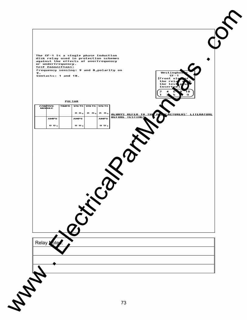
73
Relay Notes:
www . El
ectric
alPar
tMan
uals
. com
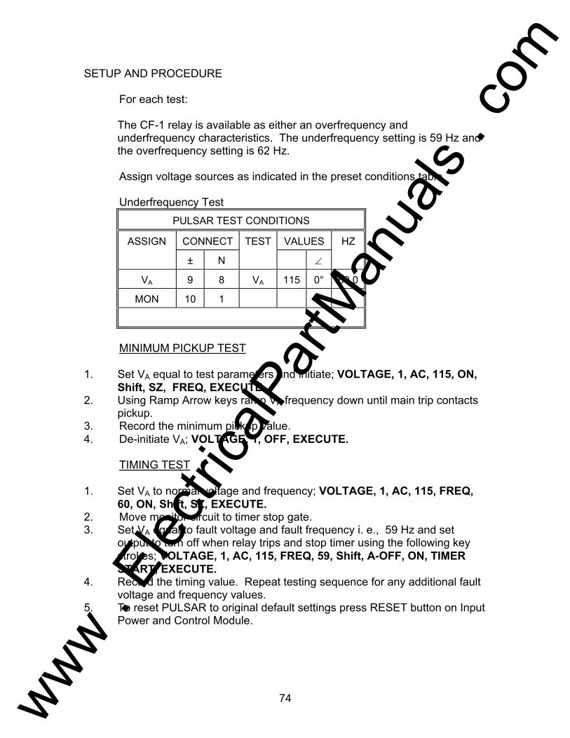
74
SETUP AND PROCEDURE For each test: The CF-1 relay is available as either an overfrequency and
underfrequency characteristics. The underfrequency setting is 59 Hz and the overfrequency setting is 62 Hz.
Assign voltage sources as indicated in the preset conditions table. Underfrequency Test
PULSAR TEST CONDITIONS
ASSIGN CONNECT TEST VALUES HZ
± N ∠
VA 9 8 VA 115 0° 60.0
MON 10 1
MINIMUM PICKUP TEST 1. Set VA equal to test parameters and initiate; VOLTAGE, 1, AC, 115, ON,
Shift, SZ, FREQ, EXECUTE. 2. Using Ramp Arrow keys ramp VA frequency down until main trip contacts
pickup. 3. Record the minimum pickup value. 4. De-initiate VA; VOLTAGE, 1, OFF, EXECUTE. TIMING TEST 1. Set VA to normal voltage and frequency; VOLTAGE, 1, AC, 115, FREQ,
60, ON, Shift, SZ, EXECUTE. 2. Move monitor circuit to timer stop gate. 3. Set VA equal to fault voltage and fault frequency i. e., 59 Hz and set
output to turn off when relay trips and stop timer using the following key strokes; VOLTAGE, 1, AC, 115, FREQ, 59, Shift, A-OFF, ON, TIMER START, EXECUTE.
4. Record the timing value. Repeat testing sequence for any additional fault voltage and frequency values.
5. To reset PULSAR to original default settings press RESET button on Input Power and Control Module.
www . El
ectric
alPar
tMan
uals
. com

75
Overfrequency Test PULSAR TEST CONDITIONS
ASSIGN CONNECT TEST VALUES HZ
± N ∠
VA 9 8 VA 115 0° 60.0
MON 10 1
MINIMUM PICKUP TEST 1. Set VA equal to test parameters and initiate; VOLTAGE, 1, AC, 115, ON,
FREQ, Shift, SZ, EXECUTE. 2. Using Ramp Arrow keys ramp VA frequency up until main trip contacts
pickup. 3. Record the minimum pickup value. 4. De-initiate VA; VOLTAGE, 1, OFF, EXECUTE. TIMING TEST 1. Set VA to normal voltage and frequency; VOLTAGE, 1, AC, 115, FREQ,
ON, Shift, SZ, EXECUTE. 2. Move monitor circuit to timer stop gate. 3. Set VA equal to fault voltage and fault frequency i. e., 62 Hz and set output
to turn off when relay trips and stop timer using the following keystrokes; VOLTAGE, 1, AC, 110, FREQ, 62, Shift, A-OFF, ON, TIMER START, EXECUTE.
4. Record the timing pickup value. Repeat testing sequence for any additional fault values.
5. To reset PULSAR to original default settings, press RESET button on Input Power and Control Module.
www . El
ectric
alPar
tMan
uals
. com
76
Testing of General Electric Type CHC11 Relay
AVO Multi-Amp PULSAR Date: September 30, 1993 Rev: B IEEE Device Number: 50 Function: Instantaneous Overcurrent Fault Detector This relay test sheet describes the use of the AVO Multi-Amp PULSAR test instrument to perform the CHC11A21 and CHC11B11 protective relay acceptance tests. Test connections to the AVO Multi-Amp PULSAR relay test set and manufacturer recommended relay settings are included. References: Manufacturer's Reference GEK-1253D Literature Test Equipment PULSAR Operating Manual Instructional Material Description of Relay The CHC11A and CHC11B relays are a complete three-phase and ground, multi-contact, high speed nondirectional overcurrent relay. The CHC11 consists of an induction cup unit for multi-phase faults and a small hinged armature unit for ground faults. The CHC11B is similar to the CHC11A except that the CHC11B has a dual rated auxiliary telephone relay "A" unit. The CHC11A and CHC11B relays may be applied wherever a high-speed fault detector is required. PRECAUTIONS ***************WARNING************** Dangerous and potentially fatal voltage can be developed across the output terminals of the PULSAR relay test set, refer to the PULSAR operation manual for further instructions. Always turn the outputs OFF before connecting, removing or touching any output terminal or test lead, use extreme caution when turning on or using the PULSAR relay test set. ALWAYS TEST THIS RELAY IN ITS CASE.
www . El
ectric
alPar
tMan
uals
. com

77
Relay Notes:
www . El
ectric
alPar
tMan
uals
. com

78
SETUP AND PROCEDURE For each test: Assign current and voltage sources as indicated in the preset conditions
table. Jumper relay terminals 4 to 6.
PULSAR TEST CONDITIONS
ASSIGN CONNECT TEST VALUES HZ
± N ∠
IA 3 5 IA 0.5 0° 60.0
IB 14 15 IB 0.5 0° 60.0
MON 1 12
IA = PFD and IB = GFD PFD - MINIMUM PICKUP 1. Set PULSAR current (IA) equal to tap value; CURRENT, 1, AC, 0.5,
EXECUTE. 2. Turn current (IA) ON; ON, EXECUTE. Using Ramp Arrow keys ramp
current channel up or down to find minimum pickup. 3. Minimum pickup should be within ±10% of tap value. Refer to relay
instruction manual for adjustment to relay. GFD - MINIMUM PICKUP 1. Connect monitor circuit to relay binding posts 2 and 16. 2. Set PULSAR current (IB) equal to tap value; CURRENT, 1, AC, 0.5,
EXECUTE. 3. Turn current (IB) ON; ON, EXECUTE. Using Ramp Arrow keys ramp
current channel up or down to find minimum pickup. 4. Minimum pickup should be within ±10% of tap value. Refer to relay
instruction manual for adjustment to relay.
www . El
ectric
alPar
tMan
uals
. com
79
Testing of Westinghouse Type CO Relay AVO Multi-Amp PULSAR Date: September 30, 1993 Rev: B IEEE Device Number: 51 Function: Overcurrent This relay test sheet describes the use of the AVO Multi-Amp PULSAR test instrument to perform the CO protective relay acceptance tests. Test connections to the AVO Multi-Amp PULSAR relay test set and manufacturer recommended relay settings are included. References: Manufacturer's Reference I.L. 41-101-Q Literature Test Equipment PULSAR Operating Manual Instructional Material Description of Relay The CO is an induction type single-phase, non directional overcurrent relay. The CO is primarily used as phase or ground overcurrent protection of feeders, transmission lines, ac generators, transformers, capacitors, reactors, and other application where a relay is required whose operating time inversely is related to operating current. PRECAUTIONS ***************WARNING************** Dangerous and potentially fatal voltage can be developed across the output terminals of the PULSAR relay test set, refer to the PULSAR operation manual for further instructions. Always turn the outputs OFF before connecting, removing or touching any output terminal or test lead, use extreme caution when turning on or using the PULSAR relay test set. ALWAYS TEST THIS RELAY IN ITS CASE.
www . El
ectric
alPar
tMan
uals
. com

80
SETUP AND PROCEDURE For each test: The CO relay test is generic, the test parameters are 2A tap and 20A
instantaneous unit. Your tap values may be different. Some relays may require that current channels be paralleled to increase VA or total current, i.e., 40 A instantaneous will require two current channels 20 amperes each (see Operating Procedures, Section 1.1, Current Sources - Parallel Operation). If more current or Volt-Amperes are needed, see Description of Controls, paragraph 1.6, High Current Interface Module and EPOCH-20/II Specifications. Assign current sources as indicated in the preset conditions table.
PULSAR TEST CONDITIONS
ASSIGN CONNECT TEST VALUES HZ
± N ∠
IA 9 8 IA 2 0° 60.0
MON 10 1
MINIMUM PICKUP TEST 1. Set IA equal to tap value; CURRENT, 1, AC, 2, ON, EXECUTE. Note that
disk is starting to creep. 2. Using the Ramp Arrow keys ramp IA up or down to determine minimum
pickup value. 3. Record the minimum pickup value. 4. De-initiate IA; CURRENT, 1, OFF, EXECUTE. TIMING TEST 1. Move monitor circuit to timer stop gate (Timer Terminal 2). 2. Set IA equal to fault current level(s) i.e., 2X; CURRENT, 1, AC, 4, ON,
Shift, A-OFF, ON, TIMER START, EXECUTE. 3. Upon contact closure of CO contacts the Timer should stop and output
turn off. Record the trip time. INSTANTANEOUS TEST 1. Move monitor circuit to terminals 10 and 2.
www . El
ectric
alPar
tMan
uals
. com

81
2. Set IA equal to 20A ; CURRENT, 1, AC, 20, Shift, A-OFF, ON, EXECUTE. 3. Turn IA ON; CURRENT, 1, ON, EXECUTE. Pulse IA up or down until main
trip contacts pickup, using the incremental steps of 1A RAMP Key 1 and the OFF, EXECUTE, ON, EXECUTE sequential commands. When relay operates, the output will automatically turn off.
4. Record pickup value. Reset A-OFF; Shift, A-OFF, OFF, EXECUTE.
www . El
ectric
alPar
tMan
uals
. com
82
Testing of Westinghouse Type CRN-1 Relay AVO Multi-Amp PULSAR Date: September 30, 1993 Rev: B IEEE Device Number: 32 Function: Directional Power This relay test sheet describes the use of the AVO Multi-Amp PULSAR test instrument to perform the CRN-1 protective relay acceptance tests. Test connections to the AVO Multi-Amp PULSAR relay test set and manufacturer recommended relay settings are included. References: Manufacturer's Reference I.L. 41-251.2K Literature Test Equipment PULSAR Operating Manual Instructional Material Description of Relay The CRN-1 relay is a single phase directionally controlled timing relay used to protect ac generators from motoring. When such a condition occurs and persists for a predetermined time interval, the generator may be tripped or an alarm sounded. PRECAUTIONS ***************WARNING************** Dangerous and potentially fatal voltage can be developed across the output terminals of the PULSAR relay test set, refer to the PULSAR operation manual for further instructions. Always turn the outputs OFF before connecting, removing or touching any output terminal or test lead, use extreme caution when turning on or using the PULSAR relay test set. ALWAYS TEST THIS RELAY IN ITS CASE.
www . El
ectric
alPar
tMan
uals
. com
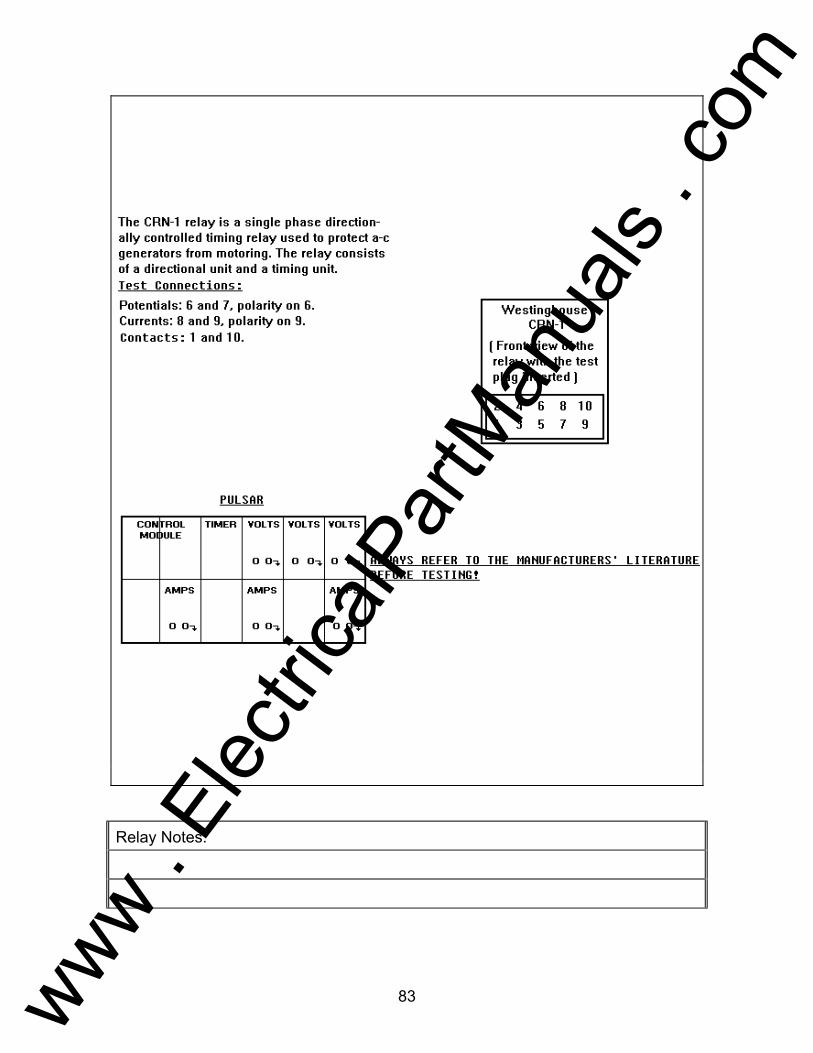
83
Relay Notes:
www . El
ectric
alPar
tMan
uals
. com
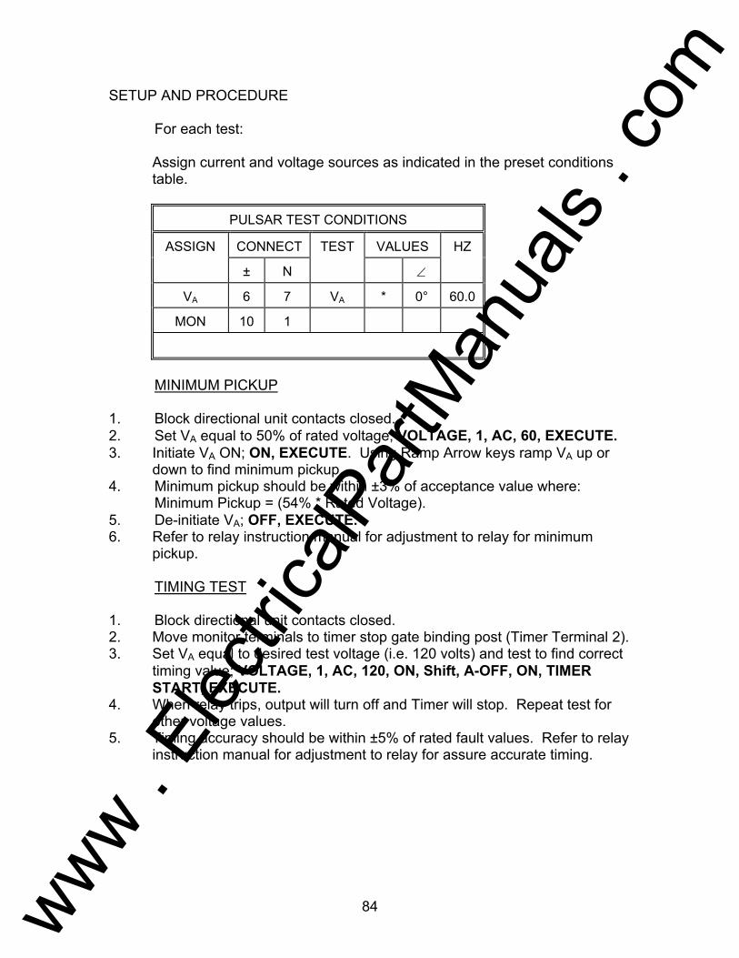
84
SETUP AND PROCEDURE For each test: Assign current and voltage sources as indicated in the preset conditions
table.
PULSAR TEST CONDITIONS
ASSIGN CONNECT TEST VALUES HZ
± N ∠
VA 6 7 VA * 0° 60.0
MON 10 1
MINIMUM PICKUP 1. Block directional unit contacts closed. 2. Set VA equal to 50% of rated voltage; VOLTAGE, 1, AC, 60, EXECUTE. 3. Initiate VA ON; ON, EXECUTE. Using Ramp Arrow keys ramp VA up or
down to find minimum pickup. 4. Minimum pickup should be within ±3% of acceptance value where: Minimum Pickup = (54% * Rated Voltage). 5. De-initiate VA; OFF, EXECUTE. 6. Refer to relay instruction manual for adjustment to relay for minimum
pickup. TIMING TEST 1. Block directional unit contacts closed. 2. Move monitor terminals to timer stop gate binding post (Timer Terminal 2). 3. Set VA equal to desired test voltage (i.e. 120 volts) and test to find correct
timing value; VOLTAGE, 1, AC, 120, ON, Shift, A-OFF, ON, TIMER START, EXECUTE.
4. When relay trips, output will turn off and Timer will stop. Repeat test for other voltage values.
5. Timing accuracy should be within ±5% of rated fault values. Refer to relay instruction manual for adjustment to relay for assure accurate timing.
www . El
ectric
alPar
tMan
uals
. com

85
PULSAR TEST CONDITIONS
ASSIGN CONNECT TEST VALUES HZ
± N ∠
VA 6 7 VA 120 0° 60.0
IA 9 8 IA 4 0° 60.0
MON 10 1
DIRECTIONAL UNIT, MAXIMUM TORQUE ANGLE 1. Set VA to rated voltage at 0°, turn VA ON; VOLTAGE, 1, AC, 120, ON,
EXECUTE. 2. Set IA to 4 amperes at 0°; CURRENT, 1, AC, 4, EXECUTE. 3. Initiate IA ON; CURRENT, 1, ON, EXECUTE. CRN-1 relay contacts
should be closed. Adjust (IA) phase angle to 240° (current leads voltage 120°); CURRENT, 1, PHASE, 240, EXECUTE. Relay contacts should be closed. Using Ramp Arrow keys, an increase of 1° leading, (239°), should cause the CRN-1 contacts to open. If contacts open greater than 1°, adjustment is required. Refer to instruction manual for proper adjustment to the back resistor.
4. De-initiate PULSAR current and voltage channels; VOLTAGE, 1, CURRENT, 1, OFF, EXECUTE. Perform this sequence whenever adjustment to relay is required or when test is completed.
DIRECTIONAL UNIT, SENSITIVITY 1. Set PULSAR voltage channel VA to rated voltage at 0°, turn VA ON;
VOLTAGE, 1, AC, 120, ON, EXECUTE. 2. Set current IA to 330° and turn current ON; CURRENT, 1, PHASE, 330,
AC, 0, ON, EXECUTE. Using Ramp Arrow keys ramp current up from 0.0 amps at 330° until CRN-1 relay contacts close. Record this current reading. Typical pickup value is .020 Amperes.
3. De-initiate PULSAR current and voltage channels; CURRENT, 1, VOLTAGE, 1, OFF, EXECUTE.
www . El
ectric
alPar
tMan
uals
. com
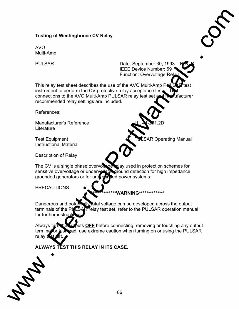
86
Testing of Westinghouse CV Relay AVO Multi-Amp PULSAR Date: September 30, 1993 Rev: B IEEE Device Number: 59 Function: Overvoltage Relay This relay test sheet describes the use of the AVO Multi-Amp PULSAR test instrument to perform the CV protective relay acceptance tests. Test connections to the AVO Multi-Amp PULSAR relay test set and manufacturer recommended relay settings are included. References: Manufacturer's Reference I.L. 41-201.2D Literature Test Equipment PULSAR Operating Manual Instructional Material Description of Relay The CV is a single phase overvoltage relay used in protection schemes for sensitive overvoltage or undervoltage ground detection for high impedance grounded generators or for ungrounded power systems. PRECAUTIONS ***************WARNING************** Dangerous and potentially fatal voltage can be developed across the output terminals of the PULSAR relay test set, refer to the PULSAR operation manual for further instructions. Always turn the outputs OFF before connecting, removing or touching any output terminal or test lead, use extreme caution when turning on or using the PULSAR relay test set. ALWAYS TEST THIS RELAY IN ITS CASE.
www . El
ectric
alPar
tMan
uals
. com
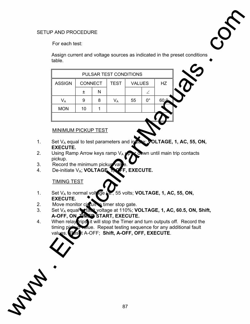
87
SETUP AND PROCEDURE For each test: Assign current and voltage sources as indicated in the preset conditions
table.
PULSAR TEST CONDITIONS
ASSIGN CONNECT TEST VALUES HZ
± N ∠
VA 9 8 VA 55 0° 60.0
MON 10 1
MINIMUM PICKUP TEST 1. Set VA equal to test parameters and initiate; VOLTAGE, 1, AC, 55, ON,
EXECUTE. 2. Using Ramp Arrow keys ramp VA up or down until main trip contacts
pickup. 3. Record the minimum pickup value. 4. De-initiate VA; VOLTAGE, 1, OFF, EXECUTE. TIMING TEST 1. Set VA to normal voltage i.e., 55 volts; VOLTAGE, 1, AC, 55, ON,
EXECUTE. 2. Move monitor circuit to timer stop gate. 3. Set VA equal to fault voltage at 110%; VOLTAGE, 1, AC, 60.5, ON, Shift,
A-OFF, ON, TIMER START, EXECUTE. 4. When relay trips, it will stop the Timer and turn outputs off. Record the
timing pickup value. Repeat testing sequence for any additional fault values. Reset A-OFF; Shift, A-OFF, OFF, EXECUTE.
www . El
ectric
alPar
tMan
uals
. com

88
Testing of Westinghouse Type CVE Relay AVO Multi-Amp PULSAR Date: September 30, 1993 Rev: B IEEE Device Number: 25 Function: Synchronizing This relay test sheet describes the use of the AVO Multi-Amp PULSAR test instrument to perform the CVE and CVE-1 protective relay acceptance tests. Test connections to the AVO Multi-Amp PULSAR relay test set and manufacturer recommended relay settings are included. References: Manufacturer's Reference I.L. 41-681.P Literature Test Equipment PULSAR Operating Manual Instructional Material Description of Relay The CVE is a synchro-verifier relay and the CVE-1 is a synchro-verifier relay with line and bus voltage sensing relays. The synchro-verifier is used to verify the condition of synchronism existing between two system voltages. The relay's contacts will close when these voltages are within the relay's set limits. PRECAUTIONS ***************WARNING************** Dangerous and potentially fatal voltage can be developed across the output terminals of the PULSAR relay test set, refer to the PULSAR operation manual for further instructions. Always turn the outputs OFF before connecting, removing or touching any output terminal or test lead, use extreme caution when turning on or using the PULSAR relay test set. ALWAYS TEST THIS RELAY IN ITS CASE.
www . El
ectric
alPar
tMan
uals
. com

89
Relay Notes:
www . El
ectric
alPar
tMan
uals
. com
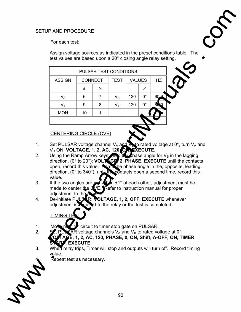
90
SETUP AND PROCEDURE For each test: Assign voltage sources as indicated in the preset conditions table. The
test values are based upon a 20° closing angle relay setting.
PULSAR TEST CONDITIONS
ASSIGN CONNECT TEST VALUES HZ
± N ∠
VA 6 7 VA 120 0° 60.0
VB 9 8 VB 120 0° 60.0
MON 10 1
CENTERING CIRCLE (CVE) 1. Set PULSAR voltage channel VA and VB to rated voltage at 0°, turn VA and
VB ON; VOLTAGE, 1, 2, AC, 120, ON, EXECUTE. 2. Using the Ramp Arrow keys ramp the phase angle for VB in the lagging
direction, (0° to 20°); VOLTAGE, 2, PHASE, EXECUTE until the contacts open, record this value. Ramp the phase angle in the, opposite, leading direction, (0° to 340°), until the contacts open a second time, record this value.
3. If the two angles are not within ±1° of each other, adjustment must be made to center the CVE. Refer to instruction manual for proper adjustment to the resistor.
4. De-initiate PULSAR; VOLTAGE, 1, 2, OFF, EXECUTE whenever adjustment is required to the relay or the test is completed.
TIMING TEST 1. Move monitor circuit to timer stop gate on PULSAR. 2. Set PULSAR voltage channels VA and VB to rated voltage at 0°;
VOLTAGE, 1, 2, AC, 120, PHASE, 0, ON, Shift, A-OFF, ON, TIMER START, EXECUTE.
3. When relay trips, Timer will stop and outputs will turn off. Record timing value.
4. Repeat test as necessary.
www . El
ectric
alPar
tMan
uals
. com
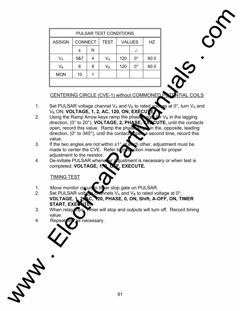
91
PULSAR TEST CONDITIONS
ASSIGN CONNECT TEST VALUES HZ
± N ∠
VA 5&7 4 VA 120 0° 60.0
VB 6 8 VB 120 0° 60.0
MON 10 1
CENTERING CIRCLE (CVE-1) without COMMONED POTENTIAL COILS 1. Set PULSAR voltage channel VA and VB to rated voltage at 0°, turn VA and
VB ON; VOLTAGE, 1, 2, AC, 120, ON, EXECUTE. 2. Using the Ramp Arrow keys ramp the phase angle for VB in the lagging
direction, (0° to 20°), VOLTAGE, 2, PHASE, EXECUTE, until the contacts open, record this value. Ramp the phase angle in the, opposite, leading direction, (0° to 340°), until the contacts open a second time, record this value.
3. If the two angles are not within ±1° of each other, adjustment must be made to center the CVE. Refer to instruction manual for proper adjustment to the resistor.
4. De-initiate PULSAR whenever adjustment is necessary or when test is completed; VOLTAGE, 1, 2, OFF, EXECUTE.
TIMING TEST 1. Move monitor circuit to timer stop gate on PULSAR. 2. Set PULSAR voltage channels VA and VB to rated voltage at 0°;
VOLTAGE, 1, 2, AC, 120, PHASE, 0, ON, Shift, A-OFF, ON, TIMER START, EXECUTE.
3. When relay trips, Timer will stop and outputs will turn off. Record timing value.
4. Repeat test as necessary.
www . El
ectric
alPar
tMan
uals
. com
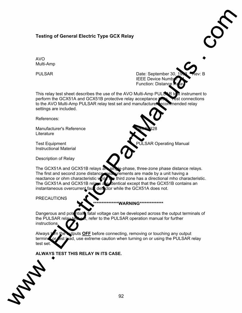
92
Testing of General Electric Type GCX Relay
AVO Multi-Amp PULSAR Date: September 30, 1993 Rev: B IEEE Device Number: 21 Function: Distance Relay This relay test sheet describes the use of the AVO Multi-Amp PULSAR test instrument to perform the GCX51A and GCX51B protective relay acceptance tests. Test connections to the AVO Multi-Amp PULSAR relay test set and manufacturer recommended relay settings are included. References: Manufacturer's Reference GEI-98328 Literature Test Equipment PULSAR Operating Manual Instructional Material Description of Relay The GCX51A and GCX51B relays are single-phase, three-zone phase distance relays. The first and second zone distance measurements are made by a unit having a reactance or ohm characteristic while the third zone has a directional mho characteristic. The GCX51A and GCX51B relays are identical except that the GCX51B contains an instantaneous overcurrent fault detector while the GCX51A does not. PRECAUTIONS ***************WARNING************** Dangerous and potentially fatal voltage can be developed across the output terminals of the PULSAR relay test set, refer to the PULSAR operation manual for further instructions. Always turn the outputs OFF before connecting, removing or touching any output terminal or test lead, use extreme caution when turning on or using the PULSAR relay test set. ALWAYS TEST THIS RELAY IN ITS CASE.
www . El
ectric
alPar
tMan
uals
. com

93
Relay Notes:
www . El
ectric
alPar
tMan
uals
. com

94
SETUP AND PROCEDURE For each test: Assign current and voltage sources as indicated in the preset conditions
table. Execute the test as defined in the PULSAR CONDITIONS table. Jumper relay terminals 7 to 8. All test values are based upon a 60° maximum torque angle and the
following formula:
PULSAR TEST CONDITIONS
ASSIGN CONNECT TEST VALUES HZ
± N ∠
VA 17 18 VA 35 0° 60.0
IA 5 10 IA 5 60° 60.0
MON * *
Z1 = 3Ω Z2 = 4Ω Z3 = 5Ω
OHMIC REACH-ZONE 1 1. Connect the Monitor circuit to the appropriate relay contacts. 2. Set IA to 5A and 60°, set VA to 35v and 0°, using the following keystrokes;
CURRENT, 1, AC, 5, PHASE, 60 , VOLTAGE, 1, AC, 35, EXECUTE. 3. Initiate PULSAR; CURRENT, 1, ON, VOLTAGE, 1, ON, EXECUTE. Using
the appropriate Ramp Arrow keys ,, ramp VA until the contacts pickup. 4. Record the pickup value,refer to the GCX51 I.L. for any adjustment. 5. Turn IA and VA, OFF whenever an adjustment is required or the test is
completed. CURRENT, 1, VOLTAGE, 1, OFF, EXECUTE.
Z = V
2xI
www . El
ectric
alPar
tMan
uals
. com

95
OHMIC MAXIMUM TORQUE ANGLE-ZONE 1 Note: To determine maximum angle of torque, adjust the phase angle
equisdistance either side of the maximum angle of torque (± 30°) and repeat the procedure used to determine the reach. The two points should be equal, if the maximum angle of torque is correct.
1. Set IA to 5A and 90°,(± 30° of MTA), set VA to 35v and 0°, using the
following keystrokes; CURRENT, 1, AC, 5, PHASE, 90, VOLTAGE, 1, AC, 35, EXECUTE.
2. Initiate PULSAR; CURRENT, 1, ON, VOLTAGE, 1, ON, EXECUTE. Using the appropriate Ramp Arrow keys ,, ramp VA until the contacts pickup.
3. Record the pickup value, refer to the GCX51 I.L. for any adjustment. 4. Turn IA and VA, OFF whenever an adjustment is required or the test is
completed. CURRENT, 1, VOLTAGE, 1, OFF, EXECUTE. 5. Repeat the same test steps for the 30° angle (± 30 of MTA).
PULSAR TEST CONDITIONS
ASSIGN CONNECT TEST VALUES HZ
± N ∠
VA 17 18 VA 45 0° 60.0
IA 5 10 IA 5 60° 60.0
MON * *
Z1 = 3Ω Z2 = 4Ω Z3 = 5Ω
OHMIC REACH-ZONE 2 1. Connect the monitor circuit to the appropriate relay contacts. 2. Manually close the OX unit or connect 125 vdc to terminals 12 (+) and 13
(-) to pickup the OX unit needed to do the Zone 2 tests. 3. Set IA to 5A and 60°, set VA to 45v and 0°, using the following keystrokes;
CURRENT, 1, AC, 5, PHASE, 60, VOLTAGE, 1, AC, 45, EXECUTE. 4. Initiate PULSAR; CURRENT, 1, ON, VOLTAGE, 1, ON, EXECUTE. Using
the appropriate Ramp Arrow keys, ,, ramp VA until the contacts pickup. 5. Record the pickup value, refer to the GCX51 I.L. for an adjustment. 6. Turn IA and VA OFF, whenever an adjustment is required or the test is
completed. CURRENT, 1, VOLTAGE, 1, OFF, EXECUTE.
www . El
ectric
alPar
tMan
uals
. com
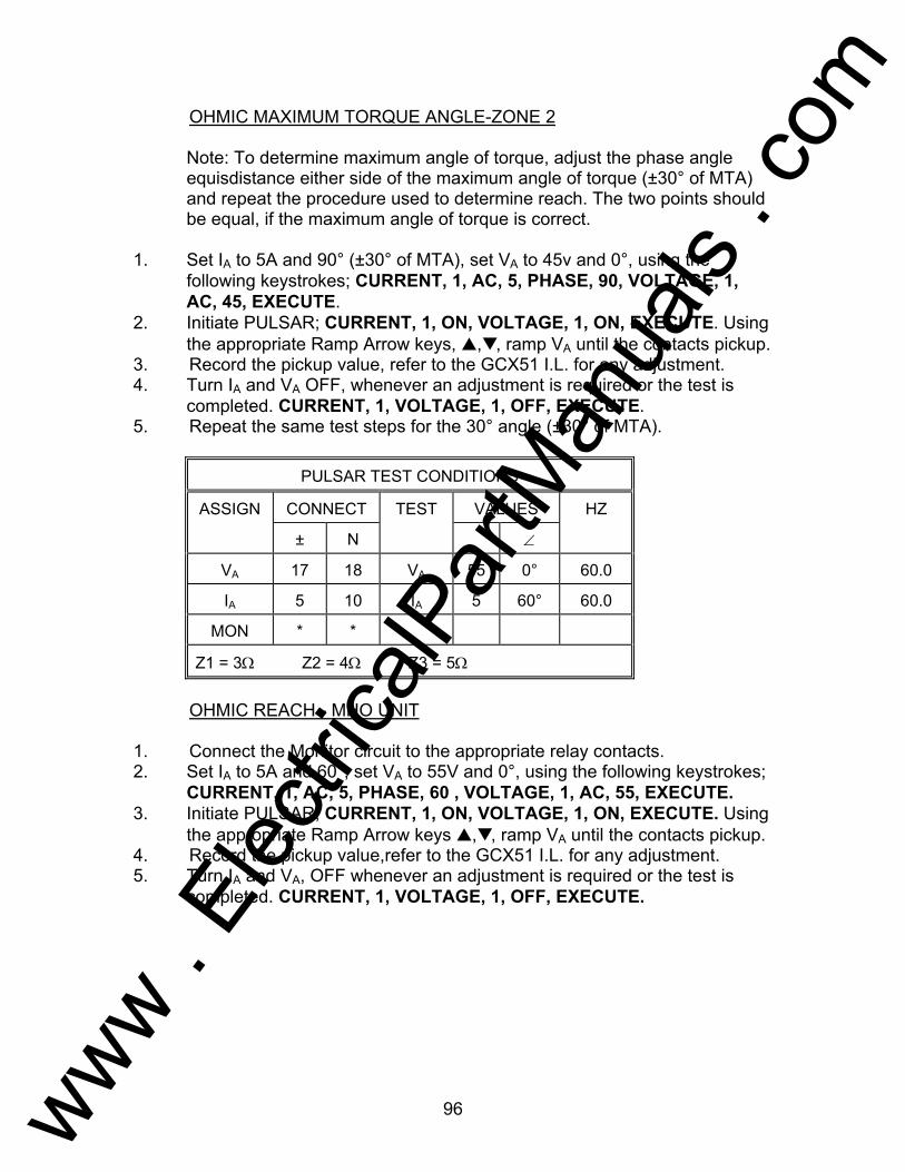
96
OHMIC MAXIMUM TORQUE ANGLE-ZONE 2 Note: To determine maximum angle of torque, adjust the phase angle
equisdistance either side of the maximum angle of torque (±30° of MTA) and repeat the procedure used to determine reach. The two points should be equal, if the maximum angle of torque is correct.
1. Set IA to 5A and 90° (±30° of MTA), set VA to 45v and 0°, using the
following keystrokes; CURRENT, 1, AC, 5, PHASE, 90, VOLTAGE, 1, AC, 45, EXECUTE.
2. Initiate PULSAR; CURRENT, 1, ON, VOLTAGE, 1, ON, EXECUTE. Using the appropriate Ramp Arrow keys, ,, ramp VA until the contacts pickup.
3. Record the pickup value, refer to the GCX51 I.L. for any adjustment. 4. Turn IA and VA OFF, whenever an adjustment is required or the test is
completed. CURRENT, 1, VOLTAGE, 1, OFF, EXECUTE. 5. Repeat the same test steps for the 30° angle (±30° of MTA).
PULSAR TEST CONDITIONS
ASSIGN CONNECT TEST VALUES HZ
± N ∠
VA 17 18 VA 55 0° 60.0
IA 5 10 IA 5 60° 60.0
MON * *
Z1 = 3Ω Z2 = 4Ω Z3 = 5Ω
OHMIC REACH - MHO UNIT 1. Connect the Monitor circuit to the appropriate relay contacts. 2. Set IA to 5A and 60°, set VA to 55V and 0°, using the following keystrokes;
CURRENT, 1, AC, 5, PHASE, 60 , VOLTAGE, 1, AC, 55, EXECUTE. 3. Initiate PULSAR; CURRENT, 1, ON, VOLTAGE, 1, ON, EXECUTE. Using
the appropriate Ramp Arrow keys ,, ramp VA until the contacts pickup. 4. Record the pickup value,refer to the GCX51 I.L. for any adjustment. 5. Turn IA and VA, OFF whenever an adjustment is required or the test is
completed. CURRENT, 1, VOLTAGE, 1, OFF, EXECUTE.
www . El
ectric
alPar
tMan
uals
. com

97
MAXIMUM TORQUE ANGLE - MHO UNIT Note: To determine maximum angle of torque, adjust the phase angle
equisdistance either side of the maximum angle of torque (±30° of MTA) and repeat the procedure used to determine reach. The two points should be equal, if the maximum angle of torque is correct.
1. Set IA to 5A and 90°,(± 30° of MTA), set VA to 55V and 0°, using the
following keystrokes; CURRENT, 1, AC, 5, PHASE, 90, VOLTAGE, 1, AC, 55, EXECUTE.
2. Initiate PULSAR; CURRENT, 1, ON, VOLTAGE, 1, ON, EXECUTE. Using the appropriate Ramp Arrow keys ,, ramp VA until the contacts pickup.
3. Record the pickup value, refer to the GCX51 I.L. for any adjustment. 4. Turn IA and VA, OFF whenever an adjustment is required or the test is
completed. CURRENT, 1, VOLTAGE, 1, OFF, EXECUTE. 5. Repeat the same test steps for the 30° angle (± 30 of MTA). OVERCURRENT UNIT PICKUP - GCX51B 1. Connect IA to GCX51B relay terminals 5 and 6 respectively. 2. Connect monitor binding posts to relay terminals 2 and 11. 3. Set IA equal to tap value at 0° and initiate IA; CURRENT, 1, PHASE, 0,
AC, 5, ON, EXECUTE. 4. Using the Ramp Arrow keys ramp current up or down to find minimum
pickup. 5. Record value and refer to GCX51B instruction manual for adjustment. 6. De-initiate PULSAR; CURRENT, 1, OFF, EXECUTE.
www . El
ectric
alPar
tMan
uals
. com

98
Testing of General Electric Type GCY Relay AVO Multi-Amp PULSAR Date: September 30, 1993 Rev: A IEEE Device Number: 21 Function: Distance Relay This relay test sheet describes the use of the AVO Multi-Amp PULSAR test instrument to perform the GCY51A protective relay acceptance tests. Test connections to the AVO Multi-Amp PULSAR relay test set and manufacturer recommended relay settings are included. References: Manufacturer's Reference GEI-98338 Literature Test Equipment PULSAR Operating Manual Instructional Material Description of Relay The GCY51 relay is a single-phase, three zone, expanded range, directional mho step distance relay for transmission line protection, phase distance relays. The GCY51 relay is used in combination with other relays and pilot channels to provide high speed protection in directional comparison and transferred tripping schemes. PRECAUTIONS ***************WARNING************** Dangerous and potentially fatal voltage can be developed across the output terminals of the PULSAR relay test set, refer to the PULSAR operation manual for further instructions. Always turn the outputs OFF before connecting, removing or touching any output terminal or test lead, use extreme caution when turning on or using the PULSAR relay test set. ALWAYS TEST THIS RELAY IN ITS CASE.
www . El
ectric
alPar
tMan
uals
. com

99
Relay Notes:
www . El
ectric
alPar
tMan
uals
. com

100
SETUP AND PROCEDURE For each test: Assign current and voltage sources as indicated in the preset conditions
table. Execute the test as defined in the PULSAR CONDITIONS table. Jumper relay terminals 4 to 5, 6 to 7, 8 to 9, 17 to 19, 18 to 20. All test values are based upon a 60° maximum torque angle, 50/ Reach,
and the following formula:
PULSAR TEST CONDITIONS
ASSIGN CONNECT TEST VALUES HZ
± N ∠
VA 17 18 VA 55 0° 60.0
IA 3 10 IA 5 60° 60.0
MON 1 11
* = Value depends on offset tap
ALWAYS REFER TO THE MANUFACTURERS' LITERATURE BEFORE TESTING! REACH TEST 1. Connect the Monitor circuit to the appropriate relay contacts. 2. Set IA to 5A and 60°, set VA to 55v and 0°, using the following keystrokes;
CURRENT, 1, AC, 5, PHASE, 60 , VOLTAGE, 1, AC, 55, EXECUTE. 3. Initiate PULSAR; CURRENT, 1, ON, VOLTAGE, 1, ON, EXECUTE. Using
the appropriate Ramp Arrow keys ,, ramp VA until the contacts pickup. 4. Record the pickup value, refer to the GCY51 I.L. for any adjustment. 5. Turn IA and VA, OFF whenever an adjustment is required or the test is
completed. CURRENT, 1, VOLTAGE, 1, OFF, EXECUTE.
Z = V
2xI
www . El
ectric
alPar
tMan
uals
. com
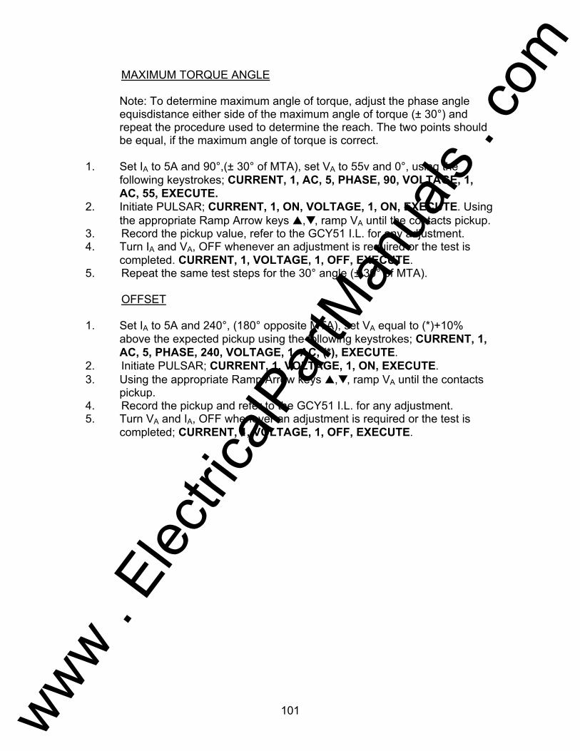
101
MAXIMUM TORQUE ANGLE Note: To determine maximum angle of torque, adjust the phase angle
equisdistance either side of the maximum angle of torque (± 30°) and repeat the procedure used to determine the reach. The two points should be equal, if the maximum angle of torque is correct.
1. Set IA to 5A and 90°,(± 30° of MTA), set VA to 55v and 0°, using the
following keystrokes; CURRENT, 1, AC, 5, PHASE, 90, VOLTAGE, 1, AC, 55, EXECUTE.
2. Initiate PULSAR; CURRENT, 1, ON, VOLTAGE, 1, ON, EXECUTE. Using the appropriate Ramp Arrow keys ,, ramp VA until the contacts pickup.
3. Record the pickup value, refer to the GCY51 I.L. for any adjustment. 4. Turn IA and VA, OFF whenever an adjustment is required or the test is
completed. CURRENT, 1, VOLTAGE, 1, OFF, EXECUTE. 5. Repeat the same test steps for the 30° angle (± 30° of MTA). OFFSET 1. Set IA to 5A and 240°, (180° opposite MTA), set VA equal to (*)+10%
above the expected pickup using the following keystrokes; CURRENT, 1, AC, 5, PHASE, 240, VOLTAGE, 1, AC, (*), EXECUTE.
2. Initiate PULSAR; CURRENT, 1, VOLTAGE, 1, ON, EXECUTE. 3. Using the appropriate Ramp Arrow keys ,, ramp VA until the contacts
pickup. 4. Record the pickup and refer to the GCY51 I.L. for any adjustment. 5. Turn VA and IA, OFF whenever an adjustment is required or the test is
completed; CURRENT, 1, VOLTAGE, 1, OFF, EXECUTE.
www . El
ectric
alPar
tMan
uals
. com
102
Testing of General Electric Type GGP Relay AVO Multi-Amp PULSAR Date: September 30, 1993 Rev: A IEEE Device Number: 32 Function: Power Directional Relay This relay test sheet describes the use of the AVO Multi-Amp PULSAR test instrument to perform the GGP53C protective relay acceptance tests. Test connections to the AVO Multi-Amp PULSAR relay test set and manufacturer recommended relay settings are included. References: Manufacturer's Reference GEK-34117C Literature Test Equipment PULSAR Operating Manual Instructional Material Description of Relay The GGP53C is a polyphase power directional relay used in protection schemes for sensitive anti-motoring protection for steam turbine generators. The relay consists of a time delay overvoltage unit (top unit) and a three-phase directional unit (bottom unit). PRECAUTIONS ***************WARNING************** Dangerous and potentially fatal voltage can be developed across the output terminals of the PULSAR relay test set, refer to the PULSAR operation manual for further instructions. Always turn the outputs OFF before connecting, removing or touching any output terminal or test lead, use extreme caution when turning on or using the PULSAR relay test set. ALWAYS TEST THIS RELAY IN ITS CASE.
www . El
ectric
alPar
tMan
uals
. com

103
Relay Notes:
www . El
ectric
alPar
tMan
uals
. com

104
SETUP AND PROCEDURE For Pick Up and Timing Test, assign current and voltage sources as
indicated in the preset conditions table below.
PULSAR TEST CONDITIONS
ASSIGN CONNECT TEST VALUES HZ
± N ∠
VA 12 2 VA * 0° 60.0
MON 1 11
PICKUP TEST (TOP UNIT) 1. Set VA equal to 40% of rated voltage and turn VA on using the following
keystrokes; VOLTAGE, 1, AC, 48, ON, EXECUTE (use 48 or 83 volts for 120 or 208 volt relays respectively).
2. Ramp VA up using the appropriate RAMP key until the contacts pickup. 3. Record the minimum pickup value (normally 50 % of rated voltage ± 3 %). 4. Turn VA OFF by pressing; OFF, EXECUTE. TIMING TEST (TOP UNIT) 1. Set VA to rated voltage by using the following keystrokes; VOLTAGE, 1,
AC, 120 (or 208), EXECUTE. NOTE: The output should not be ON yet. 2. Move monitor circuit to timer stop gate, (T2). Set output to turn off when
the relay trips by using the following keystrokes; Shift, A-OFF, ON, EXECUTE.
3. Initiate VA and start the Timer using the following keystrokes; ON, TIMER START, EXECUTE.
4. Record the timing pickup value. Repeat testing sequence for any additional time dial settings.
5. De-initiate VA if Auto-off feature was not used by pressing, OFF, EXECUTE.
PICK UP OF DIRECTIONAL UNIT (BOTTOM UNIT) 1. With reference to figure 10, GEK-34117, jumper GGP terminals 4 to 6 to
8, and jumper terminal 13 to 16. 2. Assign current and voltage sources as indicated in the following preset
conditions table. The test values defined with the (*) for IA, IB, and IC are .01 amperes (10 milliamperes). The typical pickup value is 10
www . El
ectric
alPar
tMan
uals
. com
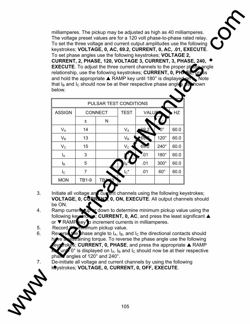
105
milliamperes. The pickup may be adjusted as high as 40 milliamperes. The voltage preset values are for a 120 volt phase-to-phase rated relay. To set the three voltage and current output amplitudes use the following keystrokes; VOLTAGE, 0, AC, 69.2, CURRENT, 0, AC, .01, EXECUTE. To set phase angles use the following keystrokes; VOLTAGE 2, CURRENT, 2, PHASE, 120, VOLTAGE 3, CURRENT, 3, PHASE, 240, EXECUTE. To adjust the three current channels to the proper phase angle relationship, use the following keystrokes; CURRENT, 0, PHASE, press and hold the appropriate RAMP key until 180° is displayed on IA. Note that IB and IC should now be at their respective phase angles as shown below.
PULSAR TEST CONDITIONS
ASSIGN CONNECT TEST VALUES HZ
± N ∠
VA 14 VA 69.2 0° 60.0
VB 13 VB 69.2 120° 60.0
VC 15 VC 69.2 240° 60.0
IA 3 IA* .01 180° 60.0
IB 5 IB* .01 300° 60.0
IC 7 IC* .01 60° 60.0
MON TB1-9 TB1-10
3. Initiate all voltage and current channels using the following keystrokes;
VOLTAGE, 0, CURRENT, 0, ON, EXECUTE. All output channels should be ON.
4. Ramp currents up or down to determine minimum pickup value using the following keystrokes; CURRENT, 0, AC, and press the least significant or RAMP key to increment currents in milliamperes.
5. Record the minimum pickup value. 6. Reverse the phase angle to IA, IB, and IC the directional contacts should
have a restraining torque. To reverse the phase angle use the following keystrokes; CURRENT, 0, PHASE, and press the appropriate RAMP key until 0° is displayed on IA. IB and IC should now be at their respective phase angles of 120° and 240°.
7. De-initiate all voltage and current channels by using the following keystrokes; VOLTAGE, 0, CURRENT, 0, OFF, EXECUTE.
www . El
ectric
alPar
tMan
uals
. com
106
Testing of Westinghouse Type HU and HU-1 Relays AVO Multi-Amp PULSAR Date: September 30, 1993 Rev: B IEEE Device Number: 87 Function: Transformer Differential This relay test sheet describes the use of the AVO Multi-Amp PULSAR test instrument to perform the HU protective relay acceptance tests. Test connections to the AVO Multi-Amp PULSAR relay test set and manufacturer recommended relay settings are included. References: Manufacturer's Reference I.L. 41-347.1Q Literature Test Equipment PULSAR Operating Manual Instructional Material Description of Relay The HU relay is a high-speed relay used in the differential protection of transformers. These relays can be applied where the magnetizing inrush current to the transformer is severe. The HU relay has two restraint transformers and two rows of taps. The HU relay has a differential unit a harmonic restrain unit, an indicating contactor switch unit and instantaneous trip unit. PRECAUTIONS ***************WARNING************** Dangerous and potentially fatal voltage can be developed across the output terminals of the PULSAR relay test set, refer to the PULSAR operation manual for further instructions. Always turn the outputs OFF before connecting, removing or touching any output terminal or test lead, use extreme caution when turning on or using the PULSAR relay test set. ALWAYS TEST THIS RELAY IN ITS CASE.
www . El
ectric
alPar
tMan
uals
. com
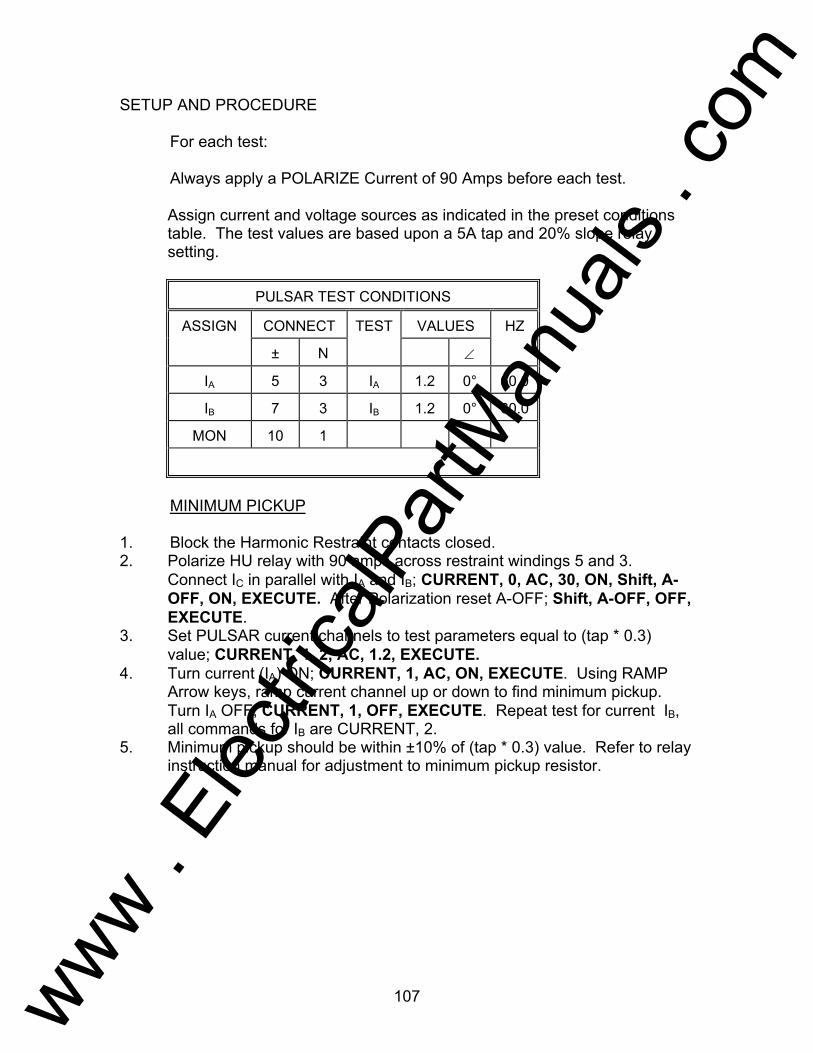
107
SETUP AND PROCEDURE For each test: Always apply a POLARIZE Current of 90 Amps before each test. Assign current and voltage sources as indicated in the preset conditions
table. The test values are based upon a 5A tap and 20% slope relay setting.
PULSAR TEST CONDITIONS
ASSIGN CONNECT TEST VALUES HZ
± N ∠
IA 5 3 IA 1.2 0° 60.0
IB 7 3 IB 1.2 0° 60.0
MON 10 1
MINIMUM PICKUP 1. Block the Harmonic Restraint contacts closed. 2. Polarize HU relay with 90 amps across restraint windings 5 and 3.
Connect IC in parallel with IA and IB; CURRENT, 0, AC, 30, ON, Shift, A-OFF, ON, EXECUTE. After Polarization reset A-OFF; Shift, A-OFF, OFF, EXECUTE.
3. Set PULSAR current channels to test parameters equal to (tap * 0.3) value; CURRENT, 1, 2, AC, 1.2, EXECUTE.
4. Turn current (IA) ON; CURRENT, 1, AC, ON, EXECUTE. Using RAMP Arrow keys, ramp current channel up or down to find minimum pickup. Turn IA OFF; CURRENT, 1, OFF, EXECUTE. Repeat test for current IB, all commands for IB are CURRENT, 2.
5. Minimum pickup should be within ±10% of (tap * 0.3) value. Refer to relay instruction manual for adjustment to minimum pickup resistor.
www . El
ectric
alPar
tMan
uals
. com
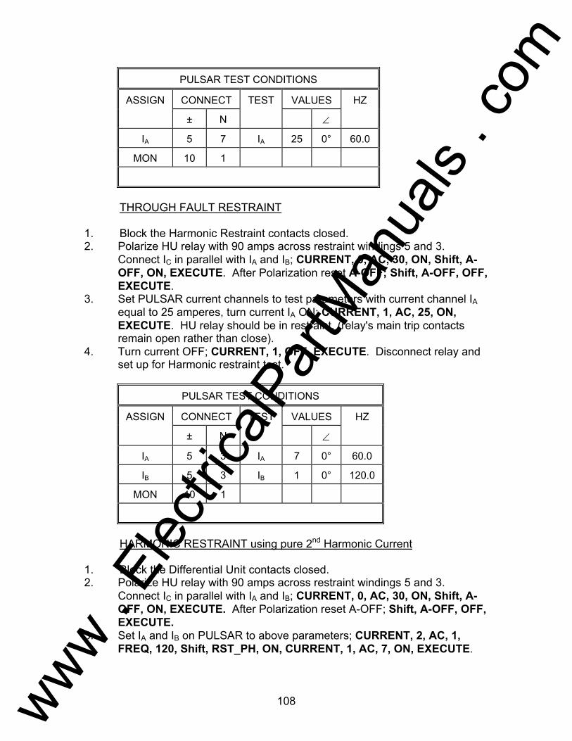
108
PULSAR TEST CONDITIONS
ASSIGN CONNECT TEST VALUES HZ
± N ∠
IA 5 7 IA 25 0° 60.0
MON 10 1
THROUGH FAULT RESTRAINT 1. Block the Harmonic Restraint contacts closed. 2. Polarize HU relay with 90 amps across restraint windings 5 and 3.
Connect IC in parallel with IA and IB; CURRENT, 0, AC, 30, ON, Shift, A-OFF, ON, EXECUTE. After Polarization reset A-OFF; Shift, A-OFF, OFF, EXECUTE.
3. Set PULSAR current channels to test parameters with current channel IA equal to 25 amperes, turn current IA ON; CURRENT, 1, AC, 25, ON, EXECUTE. HU relay should be in restraint, (relay's main trip contacts remain open rather than close).
4. Turn current OFF; CURRENT, 1, OFF, EXECUTE. Disconnect relay and set up for Harmonic restraint test.
PULSAR TEST CONDITIONS
ASSIGN CONNECT TEST VALUES HZ
± N ∠
IA 5 3 IA 7 0° 60.0
IB 5 3 IB 1 0° 120.0
MON 10 1
HARMONIC RESTRAINT using pure 2nd Harmonic Current 1. Block the Differential Unit contacts closed. 2. Polarize HU relay with 90 amps across restraint windings 5 and 3.
Connect IC in parallel with IA and IB; CURRENT, 0, AC, 30, ON, Shift, A-OFF, ON, EXECUTE. After Polarization reset A-OFF; Shift, A-OFF, OFF, EXECUTE.
3. Set IA and IB on PULSAR to above parameters; CURRENT, 2, AC, 1, FREQ, 120, Shift, RST_PH, ON, CURRENT, 1, AC, 7, ON, EXECUTE.
www . El
ectric
alPar
tMan
uals
. com

109
4. Using the Ramp Arrow keys ramp IA up or down to find pickup of harmonic restraint trip contact.
5. Record value. 6. De-initiate PULSAR if adjustment to HU relay is necessary; CURRENT, O,
OFF, EXECUTE. 7. Calculate percent harmonic with the formula as referred to under Current
Sources-Harmonic Restraint Test. 8. When test is complete, reset frequency to 60 Hz on IB; CURRENT, 2,
FREQ, 60, Shift, RST_PH, EXECUTE.
PULSAR TEST CONDITIONS
ASSIGN CONNECT TEST VALUES HZ
± N ∠
IA 5 3 IA 7 0° 60.0
IB 5 3 IB 8.89 0° 60.0
MON 10 1
HARMONIC RESTRAINT using H_WAVE (Diode Test Method) 1. Block the Differential Unit contacts closed. 2. Polarize HU relay with 90 amps across restraint windings 5 and 3.
Connect IC in parallel with IA and IB; CURRENT, 0, AC, 30, ON, Shift, A-OFF, ON, EXECUTE. After Polarization reset A-OFF; Shift, A-OFF, OFF, EXECUTE.
3. Set IA and IB on PULSAR to above parameters with IB to 8.89A, H_WAVE, to establish 4A Idc (as required for diode test method), refer to section Current Sources-Harmonic Restraint Test.; CURRENT, 2, AC, 8.89, Shift, H_WAVE, Shift, RST_PH, ON, CURRENT, 1, AC, 7, ON, EXECUTE.
4. Using the Ramp Arrow keys ramp IA up or down to find pickup of harmonic restraint trip contact.
5. Record value. 6. De-initiate PULSAR if adjustment to HU relay is necessary; CURRENT, 0,
AC, OFF, EXECUTE. 7. Refer to the manufacturers instruction literature for the appropriate %
Harmonic Curve. 8. When test is complete, restore sine wave; CURRENT, 0, Shift, SINE,
EXECUTE.
www . El
ectric
alPar
tMan
uals
. com
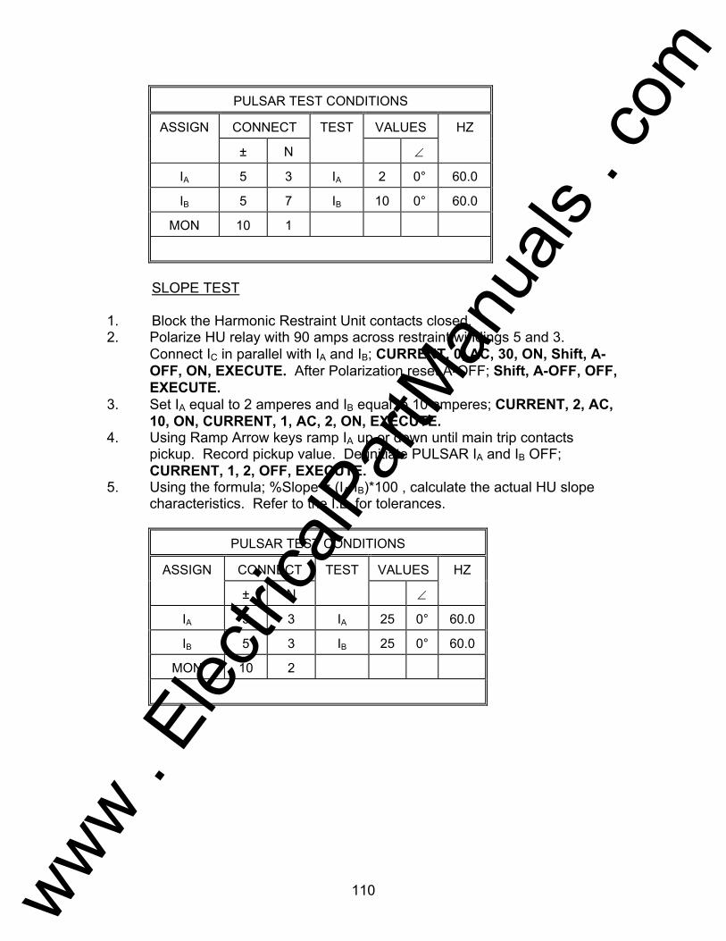
110
PULSAR TEST CONDITIONS
ASSIGN CONNECT TEST VALUES HZ
± N ∠
IA 5 3 IA 2 0° 60.0
IB 5 7 IB 10 0° 60.0
MON 10 1
SLOPE TEST 1. Block the Harmonic Restraint Unit contacts closed. 2. Polarize HU relay with 90 amps across restraint windings 5 and 3.
Connect IC in parallel with IA and IB; CURRENT, 0, AC, 30, ON, Shift, A-OFF, ON, EXECUTE. After Polarization reset A-OFF; Shift, A-OFF, OFF, EXECUTE.
3. Set IA equal to 2 amperes and IB equal to 10 amperes; CURRENT, 2, AC, 10, ON, CURRENT, 1, AC, 2, ON, EXECUTE.
4. Using Ramp Arrow keys ramp IA up or down until main trip contacts pickup. Record pickup value. De-initiate PULSAR IA and IB OFF; CURRENT, 1, 2, OFF, EXECUTE.
5. Using the formula; %Slope = (IA/IB)*100 , calculate the actual HU slope characteristics. Refer to the I.L. for tolerances.
PULSAR TEST CONDITIONS
ASSIGN CONNECT TEST VALUES HZ
± N ∠
IA 5 3 IA 25 0° 60.0
IB 5 3 IB 25 0° 60.0
MON 10 2
www . El
ectric
alPar
tMan
uals
. com
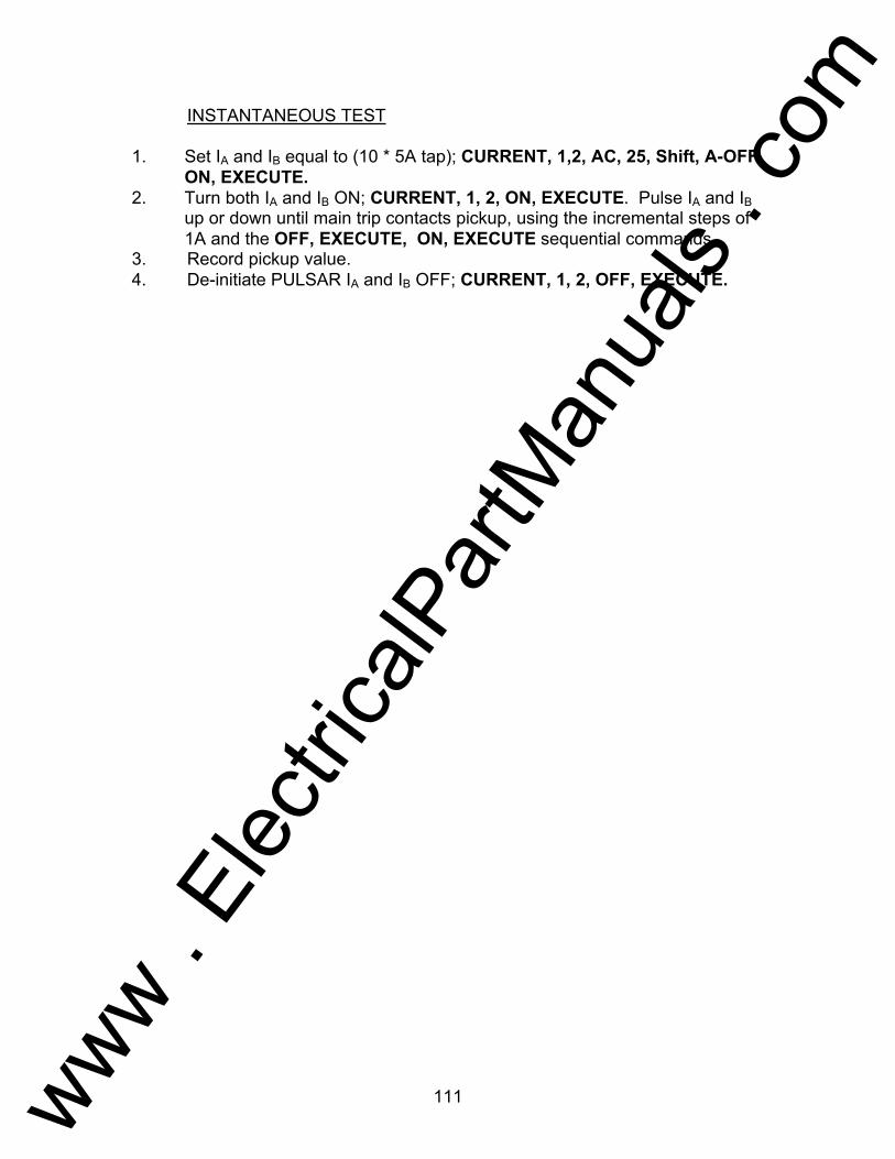
111
INSTANTANEOUS TEST 1. Set IA and IB equal to (10 * 5A tap); CURRENT, 1,2, AC, 25, Shift, A-OFF,
ON, EXECUTE. 2. Turn both IA and IB ON; CURRENT, 1, 2, ON, EXECUTE. Pulse IA and IB
up or down until main trip contacts pickup, using the incremental steps of 1A and the OFF, EXECUTE, ON, EXECUTE sequential commands.
3. Record pickup value. 4. De-initiate PULSAR IA and IB OFF; CURRENT, 1, 2, OFF, EXECUTE.
www . El
ectric
alPar
tMan
uals
. com
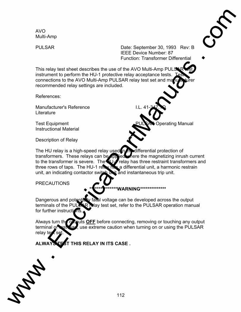
112
AVO Multi-Amp PULSAR Date: September 30, 1993 Rev: B IEEE Device Number: 87 Function: Transformer Differential This relay test sheet describes the use of the AVO Multi-Amp PULSAR test instrument to perform the HU-1 protective relay acceptance tests. Test connections to the AVO Multi-Amp PULSAR relay test set and manufacturer recommended relay settings are included. References: Manufacturer's Reference I.L. 41-347.1Q Literature Test Equipment PULSAR Operating Manual Instructional Material Description of Relay The HU relay is a high-speed relay used in the differential protection of transformers. These relays can be applied where the magnetizing inrush current to the transformer is severe. The HU-1 relay has three restraint transformers and three rows of taps. The HU-1 relay has a differential unit, a harmonic restrain unit, an indicating contactor switch unit and instantaneous trip unit. PRECAUTIONS ***************WARNING************** Dangerous and potentially fatal voltage can be developed across the output terminals of the PULSAR relay test set, refer to the PULSAR operation manual for further instructions. Always turn the outputs OFF before connecting, removing or touching any output terminal or test lead, use extreme caution when turning on or using the PULSAR relay test set. ALWAYS TEST THIS RELAY IN ITS CASE .
www . El
ectric
alPar
tMan
uals
. com

113
SETUP AND PROCEDURE For each test: Always apply a POLARIZE Current of 90 Amps before each test. Assign current and voltage sources as indicated in the preset conditions
table. The test values are based upon a 5A tap and 20% slope relay setting.
PULSAR TEST CONDITIONS
ASSIGN CONNECT TEST VALUES HZ
± N ∠
IA 5 3 IA 1.2 0° 60.0
IB 7 3 IB 1.2 0° 60.0
IC 9 3 IC 1.2 0° 60.0
MON 10 1
MINIMUM PICKUP 1. Block the Harmonic Restraint contacts closed. 2. Polarize HU relay with 90 amps across restraint windings 5 and 3.
Connect IC in parallel with IA and IB; CURRENT, 0, AC, 30, ON, Shift, A-OFF, ON, EXECUTE. After Polarization reset A-OFF; Shift, A-OFF, OFF, EXECUTE.
3. Set PULSAR current channels to test parameters equal to (tap * 0.3) value; CURRENT, 1, 2, AC, 1.2, EXECUTE.
4. Turn current (IA) ON; CURRENT, 1, AC, ON, EXECUTE. Using RAMP Arrow keys, ramp current channel up or down to find minimum pickup. Turn IA OFF; CURRENT, 1, OFF, EXECUTE. Repeat test for current IB, all commands for IB are CURRENT, 2.
5. Minimum pickup should be within ±10% of (tap * 0.3) value. Refer to relay instruction manual for adjustment to minimum pickup resistor.
www . El
ectric
alPar
tMan
uals
. com

114
PULSAR TEST CONDITIONS
ASSIGN CONNECT TEST VALUES HZ
± N ∠
IA 5 7 IA 25 0° 60.0
IB 9 7 IB 25 0° 60.0
MON 10 1
THROUGH CURRENT RESTRAINT 1. Block the Harmonic Restraint contacts closed. 2. Polarize HU relay with 90 amps across restraint windings 5 and 3.
Connect IC in parallel with IA and IB; CURRENT, 0, AC, 30, ON, Shift, A-OFF, ON, EXECUTE. After Polarization reset A-OFF; Shift, A-OFF, OFF, EXECUTE.
3. Set PULSAR current channels to test parameters with current channel IA equal to 25 amperes, turn current IA ON; CURRENT, 1, AC, 25, ON, EXECUTE. HU relay should be in restraint, (relay's main trip contacts remain open rather than close).
4. Turn current OFF; CURRENT, 1, OFF, EXECUTE. Disconnect relay and set up for Harmonic restraint test.
PULSAR TEST CONDITIONS
ASSIGN CONNECT TEST VALUES HZ
± N ∠
IA 5 3 IA 7 0° 60.0
IB 5 3 IB 1 0° 120.0
MON 10 1
HARMONIC RESTRAINT using pure 2nd Harmonic Current 1. Block the Differential Unit contacts closed. 2. Polarize HU relay with 90 amps across restraint windings 5 and 3.
Connect IC in parallel with IA and IB; CURRENT, 0, AC, 30, ON, Shift, A-OFF, ON, EXECUTE. After Polarization reset A-OFF; Shift, A-OFF, OFF, EXECUTE.
3. Set IA and IB on PULSAR to above parameters; CURRENT, 2, AC, 1, FREQ, 120, Shift, RST_PH, ON, CURRENT, 1, AC, 7, ON, EXECUTE.
www . El
ectric
alPar
tMan
uals
. com
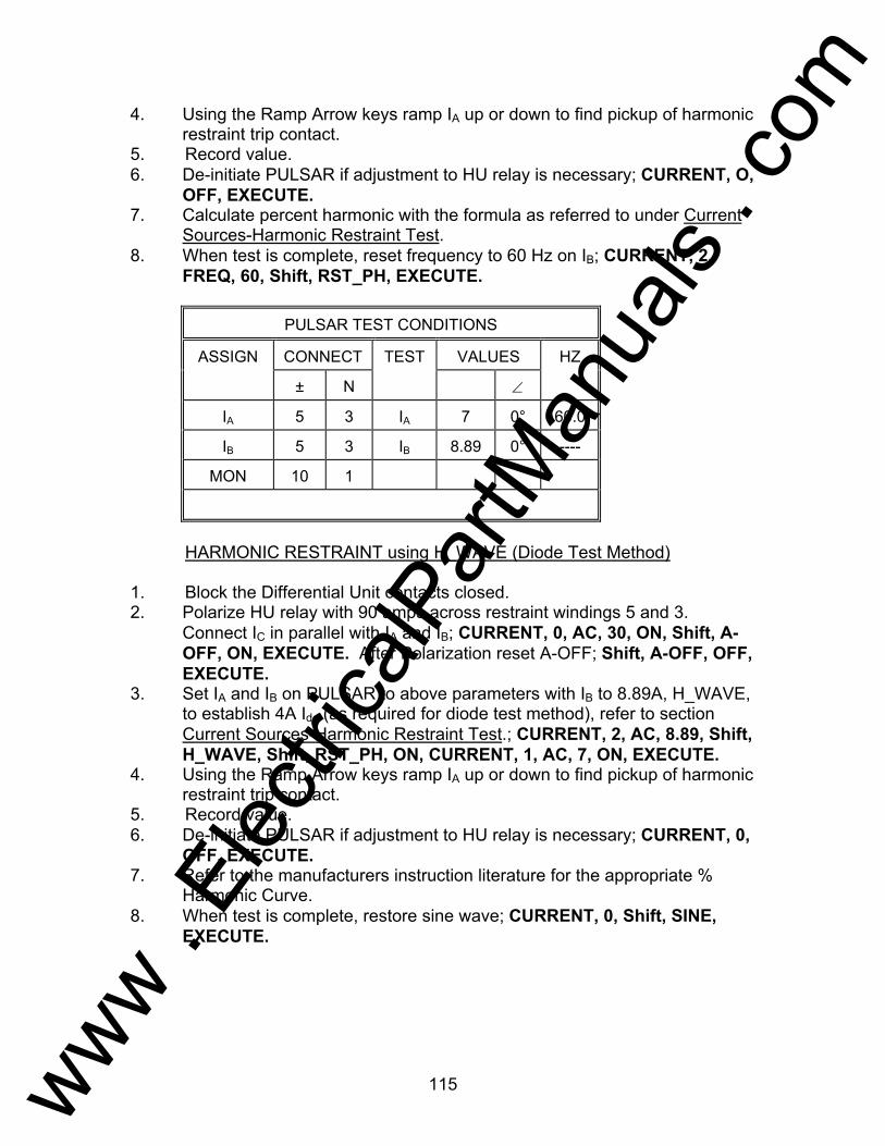
115
4. Using the Ramp Arrow keys ramp IA up or down to find pickup of harmonic restraint trip contact.
5. Record value. 6. De-initiate PULSAR if adjustment to HU relay is necessary; CURRENT, O,
OFF, EXECUTE. 7. Calculate percent harmonic with the formula as referred to under Current
Sources-Harmonic Restraint Test. 8. When test is complete, reset frequency to 60 Hz on IB; CURRENT, 2,
FREQ, 60, Shift, RST_PH, EXECUTE.
PULSAR TEST CONDITIONS
ASSIGN CONNECT TEST VALUES HZ
± N ∠
IA 5 3 IA 7 0° 60.0
IB 5 3 IB 8.89 0° ----
MON 10 1
HARMONIC RESTRAINT using H_WAVE (Diode Test Method) 1. Block the Differential Unit contacts closed. 2. Polarize HU relay with 90 amps across restraint windings 5 and 3.
Connect IC in parallel with IA and IB; CURRENT, 0, AC, 30, ON, Shift, A-OFF, ON, EXECUTE. After Polarization reset A-OFF; Shift, A-OFF, OFF, EXECUTE.
3. Set IA and IB on PULSAR to above parameters with IB to 8.89A, H_WAVE, to establish 4A Idc (as required for diode test method), refer to section Current Sources-Harmonic Restraint Test.; CURRENT, 2, AC, 8.89, Shift, H_WAVE, Shift, RST_PH, ON, CURRENT, 1, AC, 7, ON, EXECUTE.
4. Using the Ramp Arrow keys ramp IA up or down to find pickup of harmonic restraint trip contact.
5. Record value. 6. De-initiate PULSAR if adjustment to HU relay is necessary; CURRENT, 0,
OFF, EXECUTE. 7. Refer to the manufacturers instruction literature for the appropriate %
Harmonic Curve. 8. When test is complete, restore sine wave; CURRENT, 0, Shift, SINE,
EXECUTE.
www . El
ectric
alPar
tMan
uals
. com

116
PULSAR TEST CONDITIONS
ASSIGN CONNECT TEST VALUES HZ
± N ∠
IA 5 3 IA 2 0° 60.0
IB 5 7 IB 10 0° 60.0
IC 9 3 IC
MON 10 1
SLOPE TEST 1. Block the Harmonic Restraint Unit contacts closed. 2. Polarize HU relay with 90 amps across restraint windings 5 and 3.
Connect IC in parallel with IA and IB; CURRENT, 0, AC, 30, ON, Shift, A-OFF, ON, EXECUTE. After Polarization reset A-OFF; Shift, A-OFF, OFF, EXECUTE.
3. Set IA equal to 2 amperes and IB equal to 10 amperes; CURRENT, 2, AC, 10, ON, CURRENT, 1, AC, 2, ON, EXECUTE.
4. Using Ramp Arrow keys ramp IA up or down until main trip contacts pickup. Record pickup value. De-initiate PULSAR IA and IB OFF; CURRENT, 1, 2, OFF, EXECUTE.
5. Using the formula; %Slope = (IA/IB)*100 , calculate the actual HU slope characteristics. Refer to the I.L. for tolerances.
PULSAR TEST CONDITIONS
ASSIGN CONNECT TEST VALUES HZ
± N ∠
IA 5 3 IA 25 0° 60.0
IB 5 3 IB 25 0° 60.0
IC IC
MON 10 1
INSTANTANEOUS TEST 1. Set IA and IB equal to (10 * 5A tap); CURRENT, 1,2, AC, 25, Shift, A-OFF,
ON, EXECUTE. 2. Turn both IA and IB ON; CURRENT, 1, 2, ON, EXECUTE. Pulse IA and IB
up or down until main trip contacts pickup, using the incremental steps of 1A and the OFF, EXECUTE, ON, EXECUTE sequential commands.
www . El
ectric
alPar
tMan
uals
. com

117
3. Record pickup value. 4. De-initiate PULSAR IA and IB OFF; CURRENT, 1, 2, OFF, EXECUTE.
www . El
ectric
alPar
tMan
uals
. com
118
Testing General Electric Type IAC Relays AVO Multi-Amp PULSAR Date: September 30, 1993 Rev: B IEEE Device Number: 51 Function: Overcurrent This relay test sheet describes the use of the AVO Multi-Amp PULSAR test instrument to perform the IAC protective relay acceptance tests. Test connections to the AVO Multi-Amp PULSAR relay test set and manufacturer recommended relay settings are included. References: Manufacturer's Reference GEK-34053D Literature Test Equipment PULSAR Operating Manual Instructional Material Description of Relay The IAC are single-phase, current operated, ac devices with inverse time current characteristics. The IAC are utilized to protect commercial, industrial, and utility power distribution systems against either multi-phase or phase to ground faults. PRECAUTIONS ***************WARNING************** Dangerous and potentially fatal voltage can be developed across the output terminals of the PULSAR relay test set, refer to the PULSAR operation manual for further instructions. Always turn the outputs OFF before connecting, removing or touching any output terminal or test lead, use extreme caution when turning on or using the PULSAR relay test set. ALWAYS TEST THIS RELAY IN ITS CASE.
www . El
ectric
alPar
tMan
uals
. com

119
Relay Notes:
www . El
ectric
alPar
tMan
uals
. com
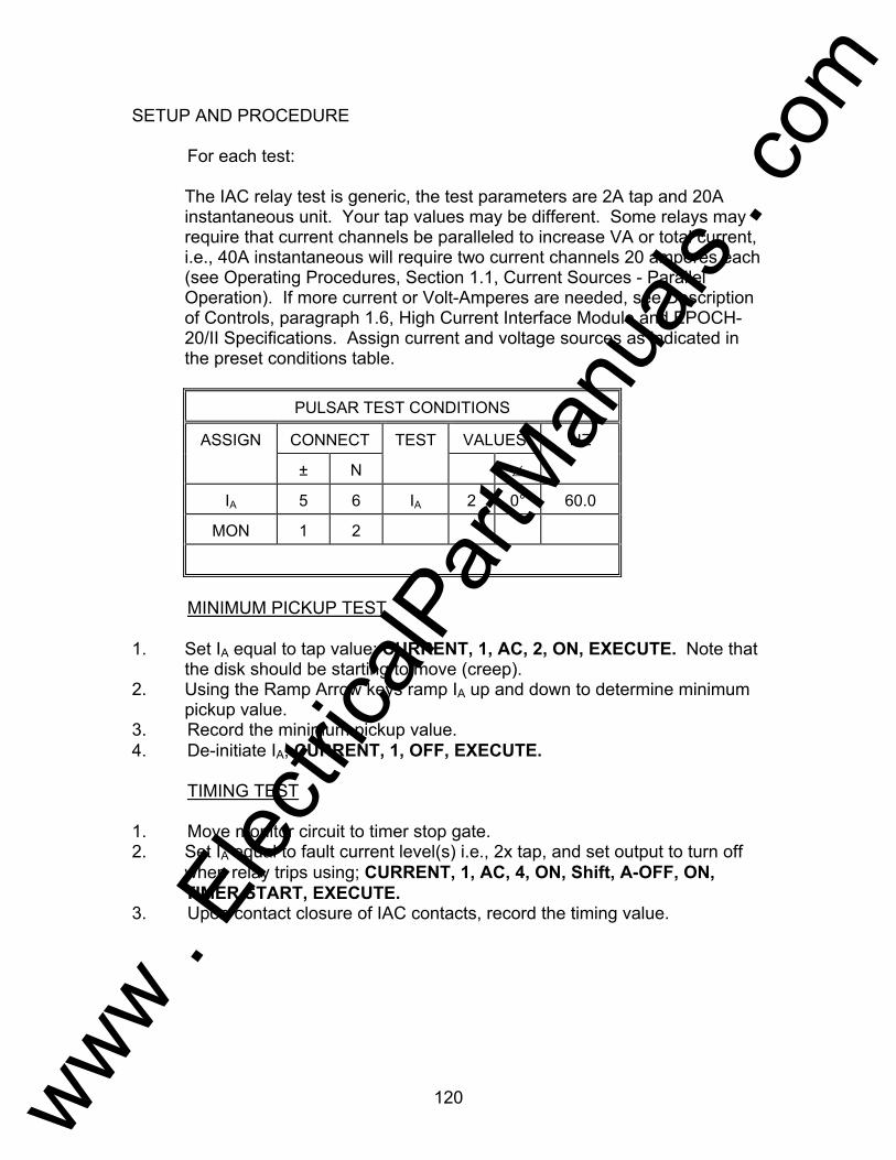
120
SETUP AND PROCEDURE For each test: The IAC relay test is generic, the test parameters are 2A tap and 20A
instantaneous unit. Your tap values may be different. Some relays may require that current channels be paralleled to increase VA or total current, i.e., 40A instantaneous will require two current channels 20 amperes each (see Operating Procedures, Section 1.1, Current Sources - Parallel Operation). If more current or Volt-Amperes are needed, see Description of Controls, paragraph 1.6, High Current Interface Module and EPOCH-20/II Specifications. Assign current and voltage sources as indicated in the preset conditions table.
PULSAR TEST CONDITIONS
ASSIGN CONNECT TEST VALUES HZ
± N ∠
IA 5 6 IA 2 0° 60.0
MON 1 2
MINIMUM PICKUP TEST 1. Set IA equal to tap value; CURRENT, 1, AC, 2, ON, EXECUTE. Note that
the disk should be starting to move (creep). 2. Using the Ramp Arrow keys ramp IA up and down to determine minimum
pickup value. 3. Record the minimum pickup value. 4. De-initiate IA; CURRENT, 1, OFF, EXECUTE. TIMING TEST 1. Move monitor circuit to timer stop gate. 2. Set IA equal to fault current level(s) i.e., 2x tap, and set output to turn off
when relay trips using; CURRENT, 1, AC, 4, ON, Shift, A-OFF, ON, TIMER START, EXECUTE.
3. Upon contact closure of IAC contacts, record the timing value.
www . El
ectric
alPar
tMan
uals
. com
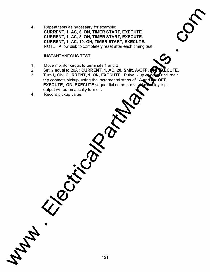
121
4. Repeat tests as necessary for example; CURRENT, 1, AC, 6, ON, TIMER START, EXECUTE. CURRENT, 1, AC, 8, ON, TIMER START, EXECUTE. CURRENT, 1, AC, 10, ON, TIMER START, EXECUTE. NOTE: Allow disk to completely reset after each timing test. INSTANTANEOUS TEST 1. Move monitor circuit to terminals 1 and 3. 2. Set IA equal to 20A ; CURRENT, 1, AC, 20, Shift, A-OFF, ON, EXECUTE. 3. Turn IA ON; CURRENT, 1, ON, EXECUTE. Pulse IA up or down until main
trip contacts pickup, using the incremental steps of 1A and the OFF, EXECUTE, ON, EXECUTE sequential commands. When relay trips, output will automatically turn off.
4. Record pickup value.
www . El
ectric
alPar
tMan
uals
. com

122
Testing General Electric IAV Relay AVO Multi-Amp PULSAR Date: September 30, 1993 Rev: B IEEE Device Number: 59 Function: Overvoltage Relay This relay test sheet describes the use of the AVO Multi-Amp PULSAR test instrument to perform the IAV protective relay acceptance tests. Test connections to the AVO Multi-Amp PULSAR relay test set and manufacturer recommended relay settings are included. References: Manufacturer's Reference GEH-1814C Literature Test Equipment PULSAR Operating Manual Instructional Material Description of Relay The IAV is a single phase overvoltage relay used in protection schemes for sensitive overvoltage ground detection for high impedance grounded generators or for ungrounded power systems. NOTE: Some IAV relays are designed to operate at frequencies and voltages other than those described here. For example, 25 Hz relays and 460 volt relays. For testing 25 Hz relays, the operator will need to select a new output frequency, see Operating Procedures, Testing Frequency Relays. For output voltages in excess of 300 volts see, Voltage Sources - Outputs Summed Together. PRECAUTIONS ***************WARNING************** Dangerous and potentially fatal voltage can be developed across the output terminals of the PULSAR relay test set, refer to the PULSAR operation manual for further instructions. Always turn the outputs OFF before connecting, removing or touching any output terminal or test lead, use extreme caution when turning on or using the PULSAR relay test set. ALWAYS TEST THIS RELAY IN ITS CASE.
www . El
ectric
alPar
tMan
uals
. com

123
Relay Notes:
www . El
ectric
alPar
tMan
uals
. com
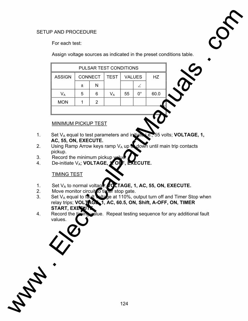
124
SETUP AND PROCEDURE For each test: Assign voltage sources as indicated in the preset conditions table.
PULSAR TEST CONDITIONS
ASSIGN CONNECT TEST VALUES HZ
± N ∠
VA 5 6 VA 55 0° 60.0
MON 1 2
MINIMUM PICKUP TEST 1. Set VA equal to test parameters and initiate i.e., 55 volts; VOLTAGE, 1,
AC, 55, ON, EXECUTE. 2. Using Ramp Arrow keys ramp VA up or down until main trip contacts
pickup. 3. Record the minimum pickup value. 4. De-initiate VA; VOLTAGE, 1, OFF, EXECUTE. TIMING TEST 1. Set VA to normal voltage; VOLTAGE, 1, AC, 55, ON, EXECUTE. 2. Move monitor circuit to timer stop gate. 3. Set VA equal to fault voltage at 110%, output turn off and Timer Stop when
relay trips; VOLTAGE, 1, AC, 60.5, ON, Shift, A-OFF, ON, TIMER START, EXECUTE.
4. Record the timing value. Repeat testing sequence for any additional fault values.
www . El
ectric
alPar
tMan
uals
. com
125
Testing General Electric Type IJF Relay AVO Multi-Amp PULSAR Date: September 30, 1993 Rev: B IEEE Device Number: 81 Function: Frequency Relay This relay test sheet describes the use of the AVO Multi-Amp PULSAR test instrument to perform the IJF protective relay acceptance tests. Test connections to the AVO Multi-Amp PULSAR relay test set and manufacturer recommended relay settings are included. References: Manufacturer's Reference GEI-19008E Literature Test Equipment PULSAR Operating Manual Instructional Material Description of Relay The IJF is a single phase induction disk relay used in protection schemes against the effects of overfrequency or underfrequency. PRECAUTIONS ***************WARNING************** Dangerous and potentially fatal voltage can be developed across the output terminals of the PULSAR relay test set, refer to the PULSAR operation manual for further instructions. Always turn the outputs OFF before connecting, removing or touching any output terminal or test lead, use extreme caution when turning on or using the PULSAR relay test set. ALWAYS TEST THIS RELAY IN ITS CASE.
www . El
ectric
alPar
tMan
uals
. com
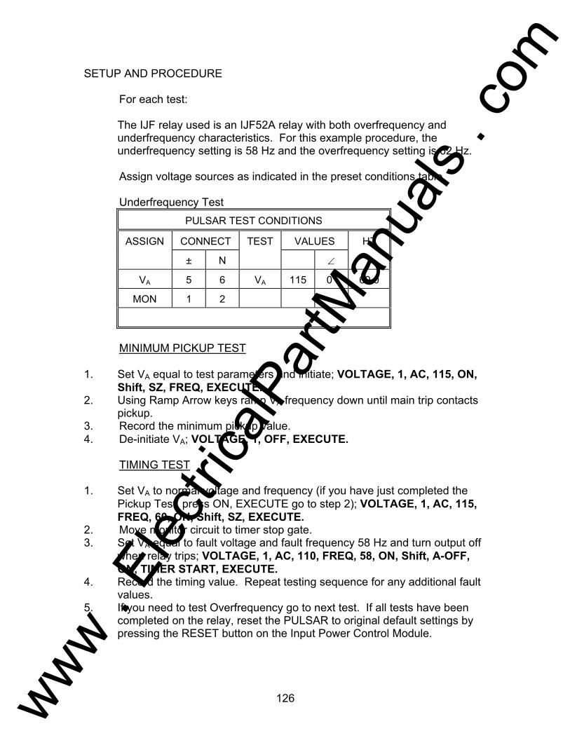
126
SETUP AND PROCEDURE For each test: The IJF relay used is an IJF52A relay with both overfrequency and
underfrequency characteristics. For this example procedure, the underfrequency setting is 58 Hz and the overfrequency setting is 62 Hz.
Assign voltage sources as indicated in the preset conditions table. Underfrequency Test
PULSAR TEST CONDITIONS
ASSIGN CONNECT TEST VALUES HZ
± N ∠
VA 5 6 VA 115 0° 60.0
MON 1 2
MINIMUM PICKUP TEST 1. Set VA equal to test parameters and initiate; VOLTAGE, 1, AC, 115, ON,
Shift, SZ, FREQ, EXECUTE. 2. Using Ramp Arrow keys ramp VA frequency down until main trip contacts
pickup. 3. Record the minimum pickup value. 4. De-initiate VA; VOLTAGE, 1, OFF, EXECUTE. TIMING TEST 1. Set VA to normal voltage and frequency (if you have just completed the
Pickup Test, press ON, EXECUTE go to step 2); VOLTAGE, 1, AC, 115, FREQ, 60, ON, Shift, SZ, EXECUTE.
2. Move monitor circuit to timer stop gate. 3. Set VA equal to fault voltage and fault frequency 58 Hz and turn output off
when relay trips; VOLTAGE, 1, AC, 110, FREQ, 58, ON, Shift, A-OFF, ON, TIMER START, EXECUTE.
4. Record the timing value. Repeat testing sequence for any additional fault values.
5. If you need to test Overfrequency go to next test. If all tests have been completed on the relay, reset the PULSAR to original default settings by pressing the RESET button on the Input Power Control Module.
www . El
ectric
alPar
tMan
uals
. com
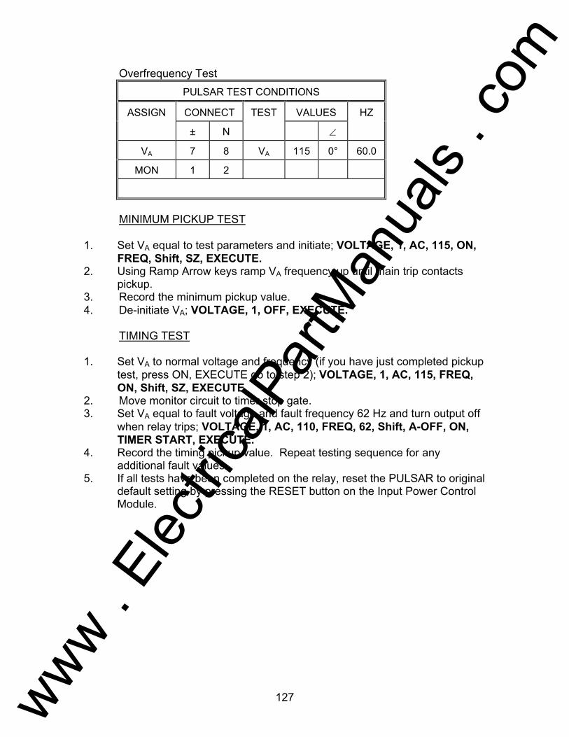
127
Overfrequency Test PULSAR TEST CONDITIONS
ASSIGN CONNECT TEST VALUES HZ
± N ∠
VA 7 8 VA 115 0° 60.0
MON 1 2
MINIMUM PICKUP TEST 1. Set VA equal to test parameters and initiate; VOLTAGE, 1, AC, 115, ON,
FREQ, Shift, SZ, EXECUTE. 2. Using Ramp Arrow keys ramp VA frequency up until main trip contacts
pickup. 3. Record the minimum pickup value. 4. De-initiate VA; VOLTAGE, 1, OFF, EXECUTE. TIMING TEST 1. Set VA to normal voltage and frequency (if you have just completed pickup
test, press ON, EXECUTE go to step 2); VOLTAGE, 1, AC, 115, FREQ, ON, Shift, SZ, EXECUTE.
2. Move monitor circuit to timer stop gate. 3. Set VA equal to fault voltage and fault frequency 62 Hz and turn output off
when relay trips; VOLTAGE, 1, AC, 110, FREQ, 62, Shift, A-OFF, ON, TIMER START, EXECUTE.
4. Record the timing pickup value. Repeat testing sequence for any additional fault values.
5. If all tests have been completed on the relay, reset the PULSAR to original default setting by pressing the RESET button on the Input Power Control Module.
www . El
ectric
alPar
tMan
uals
. com

128
Testing General Electric Type IJS Relay AVO Multi-Amp PULSAR Date: September 30, 1993 Rev: B IEEE Device Number: 25 Function: Synchronizing This relay test sheet describes the use of the AVO Multi-Amp PULSAR test instrument to perform the IJS protective relay acceptance tests. Test connections to the AVO Multi-Amp PULSAR relay test set and manufacturer recommended relay settings are included. References: Manufacturer's Reference GEH-1791 Literature Test Equipment PULSAR Operating Manual Instructional Material Description of Relay The IJS is a synchro-verifier relay with line and bus voltage sensing. The synchro-verifier is used to verify the condition of synchronism existing between two system voltages. The relay's contacts will close when these voltages are within the relay's set limits. PRECAUTIONS ***************WARNING************** Dangerous and potentially fatal voltage can be developed across the output terminals of the PULSAR relay test set, refer to the PULSAR operation manual for further instructions. Always turn the outputs OFF before connecting, removing or touching any output terminal or test lead, use extreme caution when turning on or using the PULSAR relay test set. ALWAYS TEST THIS RELAY IN ITS CASE.
www . El
ectric
alPar
tMan
uals
. com

129
Relay Notes:
www . El
ectric
alPar
tMan
uals
. com
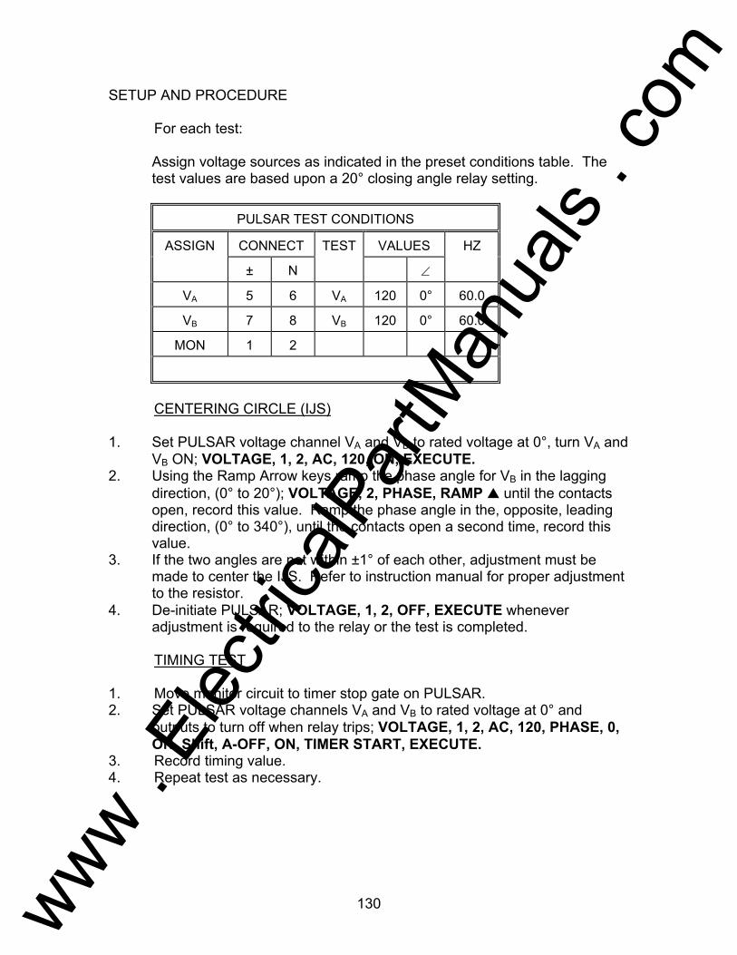
130
SETUP AND PROCEDURE For each test: Assign voltage sources as indicated in the preset conditions table. The
test values are based upon a 20° closing angle relay setting.
PULSAR TEST CONDITIONS
ASSIGN CONNECT TEST VALUES HZ
± N ∠
VA 5 6 VA 120 0° 60.0
VB 7 8 VB 120 0° 60.0
MON 1 2
CENTERING CIRCLE (IJS) 1. Set PULSAR voltage channel VA and VB to rated voltage at 0°, turn VA and
VB ON; VOLTAGE, 1, 2, AC, 120, ON, EXECUTE. 2. Using the Ramp Arrow keys ramp the phase angle for VB in the lagging
direction, (0° to 20°); VOLTAGE, 2, PHASE, RAMP until the contacts open, record this value. Ramp the phase angle in the, opposite, leading direction, (0° to 340°), until the contacts open a second time, record this value.
3. If the two angles are not within ±1° of each other, adjustment must be made to center the IJS. Refer to instruction manual for proper adjustment to the resistor.
4. De-initiate PULSAR; VOLTAGE, 1, 2, OFF, EXECUTE whenever adjustment is required to the relay or the test is completed.
TIMING TEST 1. Move monitor circuit to timer stop gate on PULSAR. 2. Set PULSAR voltage channels VA and VB to rated voltage at 0° and
outputs to turn off when relay trips; VOLTAGE, 1, 2, AC, 120, PHASE, 0, ON, Shift, A-OFF, ON, TIMER START, EXECUTE.
3. Record timing value. 4. Repeat test as necessary.
www . El
ectric
alPar
tMan
uals
. com

131
5. De-initiate PULSAR if the outputs are not off; VOLTAGE, 1, 2, OFF,
EXECUTE whenever adjustment is required to the relay or the test is completed.
www . El
ectric
alPar
tMan
uals
. com
132
Testing Westinghouse Type IRD and IRV Relays AVO Multi-Amp PULSAR Date: September 30, 1993 Rev: B IEEE Device Number: 67 Function: Directional Overcurrent This relay test sheet describes the use of the AVO Multi-Amp PULSAR test instrument to perform the IRD and IRV protective relays acceptance tests. Test connections to the AVO Multi-Amp PULSAR relay test set and manufacturer recommended relay settings are included. References: Manufacturer's Reference I.L. 41-133P Literature Test Equipment PULSAR Operating Manual Instructional Material Description of Relay The IRD is a dual polarized relay for directional ground overcurrent faults. The IRV is a directional overcurrent relay for phase protection. PRECAUTIONS ***************WARNING************** Dangerous and potentially fatal voltage can be developed across the output terminals of the PULSAR relay test set, refer to the PULSAR operation manual for further instructions. Always turn the outputs OFF before connecting, removing or touching any output terminal or test lead, use extreme caution when turning on or using the PULSAR relay test set. ALWAYS TEST THIS RELAY IN ITS CASE.
www . El
ectric
alPar
tMan
uals
. com

133
Relay Notes:
www . El
ectric
alPar
tMan
uals
. com
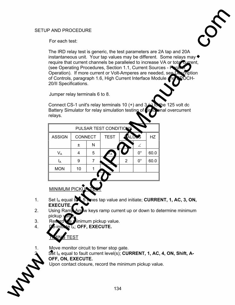
134
SETUP AND PROCEDURE For each test: The IRD relay test is generic, the test parameters are 2A tap and 20A
instantaneous unit. Your tap values may be different. Some relays may require that current channels be paralleled to increase VA or total current, (see Operating Procedures, Section 1.1, Current Sources - Parallel Operation). If more current or Volt-Amperes are needed, see Description of Controls, paragraph 1.6, High Current Interface Module and EPOCH-20/II Specifications.
Jumper relay terminals 6 to 8. Connect CS-1 unit's relay terminals 10 (+) and 3 (-) to the 125 volt dc
Battery Simulator for relay simulation testing of directional overcurrent relays.
PULSAR TEST CONDITIONS
ASSIGN CONNECT TEST VALUES HZ
± N ∠
VA 4 5 VA * 0° 60.0
IA 9 7 IA 2 0° 60.0
MON 10 1
MINIMUM PICKUP TEST 1. Set IA equal to 1.5 times tap value and initiate; CURRENT, 1, AC, 3, ON,
EXECUTE. 2. Using Ramp Arrow keys ramp current up or down to determine minimum
pickup value. 3. Record the minimum pickup value. 4. De-initiate IA; OFF, EXECUTE. TIMING TEST 1. Move monitor circuit to timer stop gate. 2. Set IA equal to fault current level(s); CURRENT, 1, AC, 4, ON, Shift, A-
OFF, ON, EXECUTE. 3. Upon contact closure, record the minimum pickup value.
www . El
ectric
alPar
tMan
uals
. com
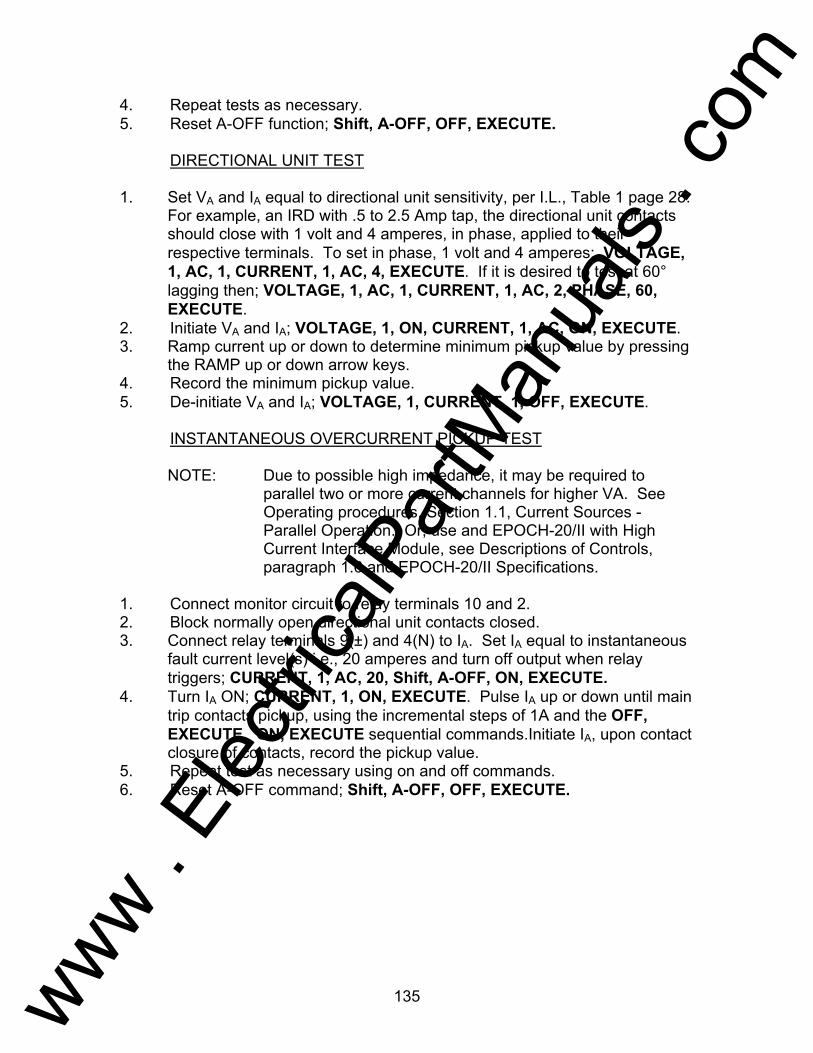
135
4. Repeat tests as necessary. 5. Reset A-OFF function; Shift, A-OFF, OFF, EXECUTE. DIRECTIONAL UNIT TEST 1. Set VA and IA equal to directional unit sensitivity, per I.L., Table 1 page 28.
For example, an IRD with .5 to 2.5 Amp tap, the directional unit contacts should close with 1 volt and 4 amperes, in phase, applied to their respective terminals. To set in phase, 1 volt and 4 amperes: VOLTAGE, 1, AC, 1, CURRENT, 1, AC, 4, EXECUTE. If it is desired to test at 60° lagging then; VOLTAGE, 1, AC, 1, CURRENT, 1, AC, 2, PHASE, 60, EXECUTE.
2. Initiate VA and IA; VOLTAGE, 1, ON, CURRENT, 1, AC, ON, EXECUTE. 3. Ramp current up or down to determine minimum pickup value by pressing
the RAMP up or down arrow keys. 4. Record the minimum pickup value. 5. De-initiate VA and IA; VOLTAGE, 1, CURRENT, 1, OFF, EXECUTE. INSTANTANEOUS OVERCURRENT PICKUP TEST
NOTE: Due to possible high impedance, it may be required to parallel two or more current channels for higher VA. See Operating procedures, Section 1.1, Current Sources - Parallel Operation. Or, use and EPOCH-20/II with High Current Interface Module, see Descriptions of Controls, paragraph 1.6 and EPOCH-20/II Specifications.
1. Connect monitor circuit to relay terminals 10 and 2. 2. Block normally open directional unit contacts closed. 3. Connect relay terminals 9(±) and 4(N) to IA. Set IA equal to instantaneous
fault current level(s) i.e., 20 amperes and turn off output when relay triggers; CURRENT, 1, AC, 20, Shift, A-OFF, ON, EXECUTE.
4. Turn IA ON; CURRENT, 1, ON, EXECUTE. Pulse IA up or down until main trip contacts pickup, using the incremental steps of 1A and the OFF, EXECUTE, ON, EXECUTE sequential commands.Initiate IA, upon contact closure of contacts, record the pickup value.
5. Repeat test as necessary using on and off commands. 6. Reset A-OFF command; Shift, A-OFF, OFF, EXECUTE.
www . El
ectric
alPar
tMan
uals
. com
136
Testing General Electric Type JBC and JBCV Relays AVO Multi-Amp PULSAR Date: September 30, 1993 Rev: B IEEE Device Number: 67 Function: Directional Overcurrent This relay test sheet describes the use of the AVO Multi-Amp PULSAR test instrument to perform the JBC and JBCV protective relays acceptance tests. Test connections to the AVO Multi-Amp PULSAR relay test set and manufacturer recommended relay settings are included. References: Manufacturer's Reference GEK-49848 & GEK-49850 Literature Test Equipment PULSAR Operating Manual Instructional Material Description of Relay The JBC is a phase directional overcurrent relay. The JBCV is a phase directional overcurrent relay with voltage restraint. Both relays are for phase protection. PRECAUTIONS ***************WARNING************** Dangerous and potentially fatal voltage can be developed across the output terminals of the PULSAR relay test set, refer to the PULSAR operation manual for further instructions. Always turn the outputs OFF before connecting, removing or touching any output terminal or test lead, use extreme caution when turning on or using the PULSAR relay test set. ALWAYS TEST THIS RELAY IN ITS CASE.
www . El
ectric
alPar
tMan
uals
. com
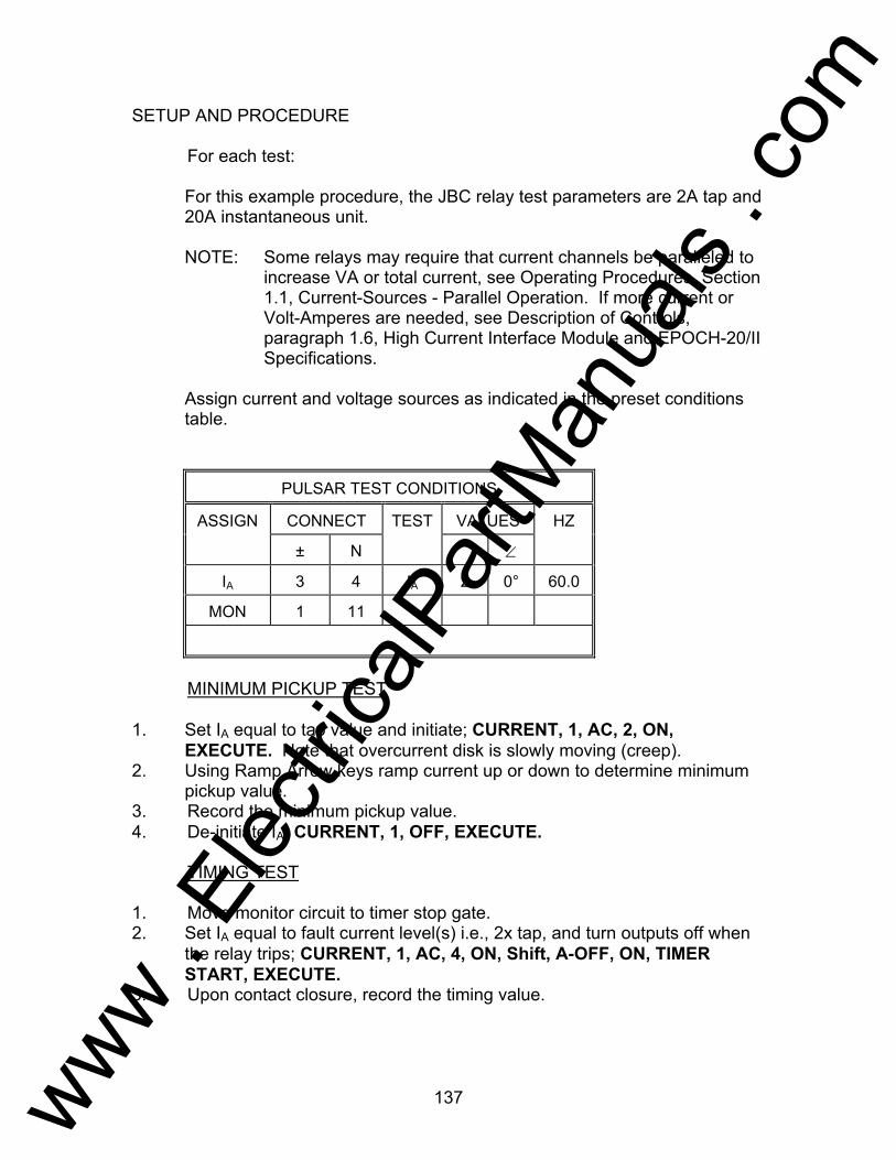
137
SETUP AND PROCEDURE For each test: For this example procedure, the JBC relay test parameters are 2A tap and
20A instantaneous unit.
NOTE: Some relays may require that current channels be paralleled to increase VA or total current, see Operating Procedures, Section 1.1, Current-Sources - Parallel Operation. If more current or Volt-Amperes are needed, see Description of Controls, paragraph 1.6, High Current Interface Module and EPOCH-20/II Specifications.
Assign current and voltage sources as indicated in the preset conditions
table.
PULSAR TEST CONDITIONS
ASSIGN CONNECT TEST VALUES HZ
± N ∠
IA 3 4 IA 2 0° 60.0
MON 1 11
MINIMUM PICKUP TEST 1. Set IA equal to tap value and initiate; CURRENT, 1, AC, 2, ON,
EXECUTE. Note that overcurrent disk is slowly moving (creep). 2. Using Ramp Arrow keys ramp current up or down to determine minimum
pickup value. 3. Record the minimum pickup value. 4. De-initiate IA; CURRENT, 1, OFF, EXECUTE. TIMING TEST 1. Move monitor circuit to timer stop gate. 2. Set IA equal to fault current level(s) i.e., 2x tap, and turn outputs off when
the relay trips; CURRENT, 1, AC, 4, ON, Shift, A-OFF, ON, TIMER START, EXECUTE.
3. Upon contact closure, record the timing value.
www . El
ectric
alPar
tMan
uals
. com

138
4. Repeat tests as necessary. 5. Reset A-OFF function; Shift, A-OFF, OFF, EXECUTE.
PULSAR TEST CONDITIONS
ASSIGN CONNECT TEST VALUES HZ
± N ∠
VA 7 8 VA 115 * 60.0
IA 5 6 IA 2 0° 60.0
MON 1 11
DIRECTIONAL UNIT TEST 1. Set VA and IA for directional unit polarity check based on Figure 24 of
instruction manual and table parameters below. Refer to Phase Angle Relationships Section. All current angles in JBC instruction manual are leading angles, those listed below are lagging angles.
2. Ramp current up or down to determine minimum pickup value. 3. Record the minimum pickup value.
P.F. Angle - Lag 90-135 135-180 180-225 225-270 270-315 315-360 0-45 45-90
Power Flow KW IN/OUT
OUT IN IN IN IN OUT OUT OUT
4. Contacts should be closed when KW flow is IN and open when KW flow is
out. 5. De-initiate VA and IA; VOLTAGE, 1, CURRENT, 1, OFF, EXECUTE. INSTANTANEOUS OVERCURRENT PICKUP TEST 1. Connect monitor circuit to relay terminals 1 and 12. 2. Block normally open directional unit contacts closed. 3. Connect relay terminals 2(±) and 3(N) to IA. Set IA equal to instantaneous
fault current level(s) i. e., 20 amperes and turn outputs off when relay trips; CURRENT, 1, AC, 20, Shift, A-OFF, ON, EXECUTE.
4. Turn IA ON; CURRENT, 1, ON, EXECUTE. Pulse IA up or down until main trip contacts pickup, using the incremental steps of 1A and the OFF, EXECUTE, ON, EXECUTE sequential commands. Record the pickup value.
www . El
ectric
alPar
tMan
uals
. com

139
5. Repeat test as necessary using on and off commands. 6. Reset A-OFF command; Shift, A-OFF, OFF, EXECUTE.
www . El
ectric
alPar
tMan
uals
. com
140
Testing General Electric Type JBCG51 Relay AVO Multi-Amp PULSAR Date: September 30, 1993 Rev: B IEEE Device Number: 67 Function: Directional Overcurrent This relay test sheet describes the use of the AVO Multi-Amp PULSAR test instrument to perform the JBCG51E protective relays acceptance tests. Test connections to the AVO Multi-Amp PULSAR relay test set and manufacturer recommended relay settings are included. References: Manufacturer's Reference GEK-49849A Literature Test Equipment PULSAR Operating Manual Instructional Material Description of Relay The JBCG51E is a ground directional overcurrent relay used primarily for the protection of feeders and transmission lines. They are available with inverse, very inverse, or extremely inverse time characteristics. PRECAUTIONS ***************WARNING************** Dangerous and potentially fatal voltage can be developed across the output terminals of the PULSAR relay test set, refer to the PULSAR operation manual for further instructions. Always turn the outputs OFF before connecting, removing or touching any output terminal or test lead, use extreme caution when turning on or using the PULSAR relay test set. ALWAYS TEST THIS RELAY IN ITS CASE.
www . El
ectric
alPar
tMan
uals
. com
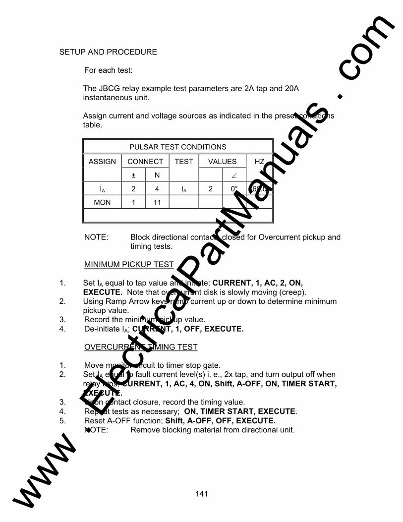
141
SETUP AND PROCEDURE For each test: The JBCG relay example test parameters are 2A tap and 20A
instantaneous unit. Assign current and voltage sources as indicated in the preset conditions
table.
PULSAR TEST CONDITIONS
ASSIGN CONNECT TEST VALUES HZ
± N ∠
IA 2 4 IA 2 0° 60.0
MON 1 11
NOTE: Block directional contacts closed for Overcurrent pickup and
timing tests. MINIMUM PICKUP TEST 1. Set IA equal to tap value and initiate; CURRENT, 1, AC, 2, ON,
EXECUTE. Note that overcurrent disk is slowly moving (creep). 2. Using Ramp Arrow keys ramp current up or down to determine minimum
pickup value. 3. Record the minimum pickup value. 4. De-initiate IA; CURRENT, 1, OFF, EXECUTE. OVERCURRENT TIMING TEST 1. Move monitor circuit to timer stop gate. 2. Set IA equal to fault current level(s) i. e., 2x tap, and turn output off when
relay trips; CURRENT, 1, AC, 4, ON, Shift, A-OFF, ON, TIMER START, EXECUTE.
3. Upon contact closure, record the timing value. 4. Repeat tests as necessary; ON, TIMER START, EXECUTE. 5. Reset A-OFF function; Shift, A-OFF, OFF, EXECUTE. NOTE: Remove blocking material from directional unit.
www . El
ectric
alPar
tMan
uals
. com
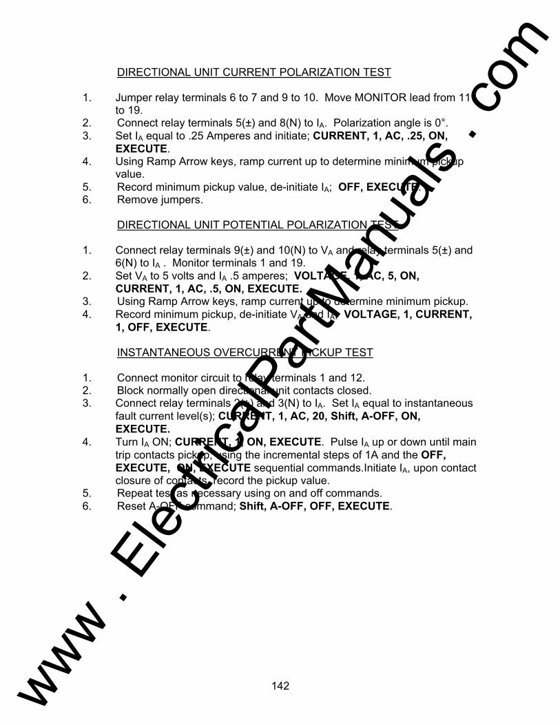
142
DIRECTIONAL UNIT CURRENT POLARIZATION TEST 1. Jumper relay terminals 6 to 7 and 9 to 10. Move MONITOR lead from 11
to 19. 2. Connect relay terminals 5(±) and 8(N) to IA. Polarization angle is 0°. 3. Set IA equal to .25 Amperes and initiate; CURRENT, 1, AC, .25, ON,
EXECUTE. 4. Using Ramp Arrow keys, ramp current up to determine minimum pickup
value. 5. Record minimum pickup value, de-initiate IA; OFF, EXECUTE. 6. Remove jumpers. DIRECTIONAL UNIT POTENTIAL POLARIZATION TEST 1. Connect relay terminals 9(±) and 10(N) to VA and relay terminals 5(±) and
6(N) to IA . Monitor terminals 1 and 19. 2. Set VA to 5 volts and IA .5 amperes; VOLTAGE, 1, AC, 5, ON,
CURRENT, 1, AC, .5, ON, EXECUTE. 3. Using Ramp Arrow keys, ramp current up to determine minimum pickup. 4. Record minimum pickup, de-initiate VA and IA; VOLTAGE, 1, CURRENT,
1, OFF, EXECUTE. INSTANTANEOUS OVERCURRENT PICKUP TEST 1. Connect monitor circuit to relay terminals 1 and 12. 2. Block normally open directional unit contacts closed. 3. Connect relay terminals 2(±) and 3(N) to IA. Set IA equal to instantaneous
fault current level(s); CURRENT, 1, AC, 20, Shift, A-OFF, ON, EXECUTE.
4. Turn IA ON; CURRENT, 1, ON, EXECUTE. Pulse IA up or down until main trip contacts pickup, using the incremental steps of 1A and the OFF, EXECUTE, ON, EXECUTE sequential commands.Initiate IA, upon contact closure of contacts, record the pickup value.
5. Repeat test as necessary using on and off commands. 6. Reset A-OFF command; Shift, A-OFF, OFF, EXECUTE.
www . El
ectric
alPar
tMan
uals
. com
143
Testing Westinghours Type KA Relay AVO Multi-Amp PULSAR Date: September 30, 1992 Rev: A IEEE Device Number: 85 Function: Carrier Auxiliary This relay test sheet describes the use of the AVO Multi-Amp PULSAR test instrument to perform the KA-4 protective relay acceptance tests. Test connections to the AVO Multi-Amp PULSAR relay test set and manufacturer recommended relay settings are included. References: Manufacturer's Reference I.L. 41-923.4M Literature Test Equipment PULSAR Operating Manual Instructional Material Description of Relay The KA-4 relay is an auxiliary relay used in the type KD directional comparison tripping system. The KA-4 provides a circuit for high-speed tripping, controls the transfer tripping signal for remote line terminals and supplies necessary coordination during power reversal conditions. PRECAUTIONS ***************WARNING************** Dangerous and potentially fatal voltage can be developed across the output terminals of the PULSAR relay test set, refer to the PULSAR operation manual for further instructions. Always turn the outputs OFF before connecting, removing or touching any output terminal or test lead, use extreme caution when turning on or using the PULSAR relay test set. ALWAYS TEST THIS RELAY IN ITS CASE.
www . El
ectric
alPar
tMan
uals
. com

144
SETUP AND PROCEDURE For each test: Assign current and voltage sources as indicated in the preset conditions
table.
PULSAR TEST CONDITIONS
ASSIGN CONNECT TEST VALUES HZ
± N ∠
VA * * VA * dc dc
IA * * IA * 0° 60.0
MON * *
OVERCURRENT MINIMUM PICKUP TEST 1. Connect relay terminals 17(±) and 16(N) to IA. 2. Set IA at 0.2 amps; CURRENT, 1, AC, 0.2, ON, EXECUTE. Using the
Ramp Arrow keys ramp current up until normally closed contacts 'just open' to determine minimum pickup value
3. Record the minimum carrier start value. 4. De-initiate IA; OFF, EXECUTE. CSP UNIT PICKUP TEST 1. Connect relay terminals 2(±) and 1(N) to VA, with VA set to dc voltage.
Monitor circuit should be connected directly across CSP normally open contacts; VOLTAGE, 1, DC, 125, ON, EXECUTE.
2. Refer to KA-4 relay settings on CSP and ramp dc voltage until CSP contacts close. This dc voltage value should be within (±5%) of rated dc voltage.
3. Record the CSP minimum pickup value. 4. De-initiate VA; OFF, EXECUTE. CSG UNIT PICKUP TEST 1. Connect relay terminals 20(±) and 1(N) to VA, with VA set to dc voltage.
Monitor circuit should be connected directly across CSP normally open contacts; VOLTAGE, 1, DC, 125, ON, EXECUTE.
www . El
ectric
alPar
tMan
uals
. com

145
2. Refer to KA-4 relay settings on CSG and ramp dc voltage until CSG contacts close. This dc voltage value should be within (±5%) of rated dc voltage.
3. Record the CSG minimum pickup value. 4. De-initiate VA; OFF, EXECUTE. SQUELCH UNIT PICKUP TEST 1. Connect relay terminals 4(±) and 3(N) to VA, with VA set to dc voltage.
Monitor circuit should be connected directly across SQUELCH UNIT normally open contacts; VOLTAGE, 1, DC, 125, ON, EXECUTE.
2. Refer to KA-4 relay settings on SQUELCH UNIT and ramp dc voltage until SQUELCH UNIT contacts close. This dc voltage value should be within (±5%) of rated dc voltage.
3. Record the SQUELCH UNIT minimum pickup value. 4. De-initiate VA; OFF, EXECUTE. ZENER DIODE TEST 1. Connect relay terminals 9(±) and 8(N) to IA. 2. Set IA equal to 200mA and initiate IA; CURRENT, 1, AC, 0.2, ON,
EXECUTE. 3. Using an external voltmeter connected in parallel across relay terminal 8
and 9, the output voltage through the zener diode should not exceed 3.5 volts.
4. De-initiate IA; OFF, EXECUTE. RECEIVER UNIT TEST 1. Refer to I.L. 41-923.4M for detailed instructions.
www . El
ectric
alPar
tMan
uals
. com
146
Testing Westinghourse Type KC Relay AVO Multi-Amp PULSAR Date: September 30, 1993 Rev: B IEEE Device Number: 50 Function: Instantaneous Overcurrent This relay test sheet describes the use of the AVO Multi-Amp PULSAR test instrument to perform the KC-2 and KC-4 protective relays acceptance tests. Test connections to the AVO Multi-Amp PULSAR relay test set and manufacturer recommended relay settings are included. References: Manufacturer's Reference I.L.41-776.F Literature Test Equipment PULSAR Operating Manual Instructional Material Description of Relay The KC relay is a non-directional current or fault detector which operates for all phase and ground faults to supervise the tripping of other relays. The KC relay is well suited to breaker failure relaying for indicating the presence or loss of current flow in the circuit breaker. The KC relay could be used in a single bus/single breaker, ring bus or breaker and one-half scheme. The KC relays consist of either one or two phase instantaneous overcurrent units, one ground instantaneous unit and an indicating contactor switch. Each instantaneous overcurrent unit consists of an induction cylinder, capacitor, varistor and a transformer. The components are connected that a contact closing torque is produced when the current exceeds the specified tap value. PRECAUTIONS ***************WARNING************** Dangerous and potentially fatal voltage can be developed across the output terminals of the PULSAR relay test set, refer to the PULSAR operating manual for further instructions. Always turn the outputs OFF before connecting, removing or touching any output terminal or test lead, use extreme caution when turning on or using the PULSAR relay test set. ALWAYS TEST THIS RELAY IN ITS CASE.
www . El
ectric
alPar
tMan
uals
. com
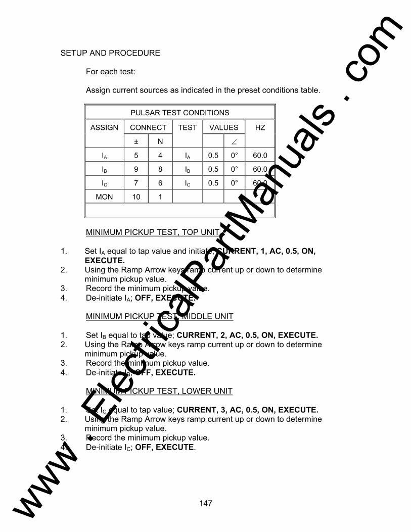
147
SETUP AND PROCEDURE For each test: Assign current sources as indicated in the preset conditions table.
PULSAR TEST CONDITIONS
ASSIGN CONNECT TEST VALUES HZ
± N ∠
IA 5 4 IA 0.5 0° 60.0
IB 9 8 IB 0.5 0° 60.0
IC 7 6 IC 0.5 0° 60.0
MON 10 1
MINIMUM PICKUP TEST, TOP UNIT 1. Set IA equal to tap value and initiate; CURRENT, 1, AC, 0.5, ON,
EXECUTE. 2. Using the Ramp Arrow keys ramp current up or down to determine
minimum pickup value. 3. Record the minimum pickup value. 4. De-initiate IA; OFF, EXECUTE. MINIMUM PICKUP TEST, MIDDLE UNIT 1. Set IB equal to tap value; CURRENT, 2, AC, 0.5, ON, EXECUTE. 2. Using the Ramp Arrow keys ramp current up or down to determine
minimum pickup value. 3. Record the minimum pickup value. 4. De-initiate IB; OFF, EXECUTE. MINIMUM PICKUP TEST, LOWER UNIT 1. Set IC equal to tap value; CURRENT, 3, AC, 0.5, ON, EXECUTE. 2. Using the Ramp Arrow keys ramp current up or down to determine
minimum pickup value. 3. Record the minimum pickup value. 4. De-initiate IC; OFF, EXECUTE.
www . El
ectric
alPar
tMan
uals
. com

148
TIMING TEST 1. Repeat similar procedures for top unit, middle unit and bottom unit. 2. Move monitor circuit to timer stop gate. 3. Set IA, IB, IC equal to fault current level(s) i. e., 2x tap and turn outputs off
when relay trips; CURRENT, 0, AC, 1.0, ON, Shift, A-OFF, ON, EXECUTE. This command will set all 3 current channels simultaneously.
4. Initiate IA, IB, IC independently using the following commands; CURRENT, 1, ON, TIMER START, EXECUTE. Repeat for CURRENT 2 and 3.
5. Repeat tests as necessary. 6. Reset A-OFF function; Shift, A-OFF, OFF, EXECUTE.
www . El
ectric
alPar
tMan
uals
. com

149
Testing Westinghouse KD Relay AVO Multi-Amp PULSAR Date: September 30, 1993 Rev: B IEEE Device Number: 21 Function: Distance This relay test sheet describes the use of the AVO Multi-Amp PULSAR test instrument to perform the KD-4, KD-10, KD-11 and KD-41 protective relays acceptance tests. Test connections to the AVO Multi-Amp PULSAR relay test set and manufacturer recommended relay settings are included. References: Manufacturer's Reference I.L. 41-490D & 41-491.4N Literature Test Equipment PULSAR Operating Manual Instructional Material Description of Relay The KD relay designed by Westinghouse Electric Corporation (ABB). The KD compensator relay is designed where a polyphase four-pole cylinder relay unit is used for the 3-phase and another polyphase unit is used for the phase-to-phase unit. This allows the KD relay 3-phase unit to respond to 3-phase faults and the phase-to-phase unit to respond to phase-to-phase faults. Between these two units, one or the other unit will respond to any double-phase-to-ground fault, regardless of which pair of phases is involved. PRECAUTIONS ***************WARNING************** Dangerous and potentially fatal voltage can be developed across the output terminals of the PULSAR relay test set, refer to the PULSAR operation manual for further instructions. Always turn the outputs OFF before connecting, removing or touching any output terminal or test lead, use extreme caution when turning on or using the PULSAR relay test set. ALWAYS TEST THIS RELAY IN ITS CASE.
www . El
ectric
alPar
tMan
uals
. com
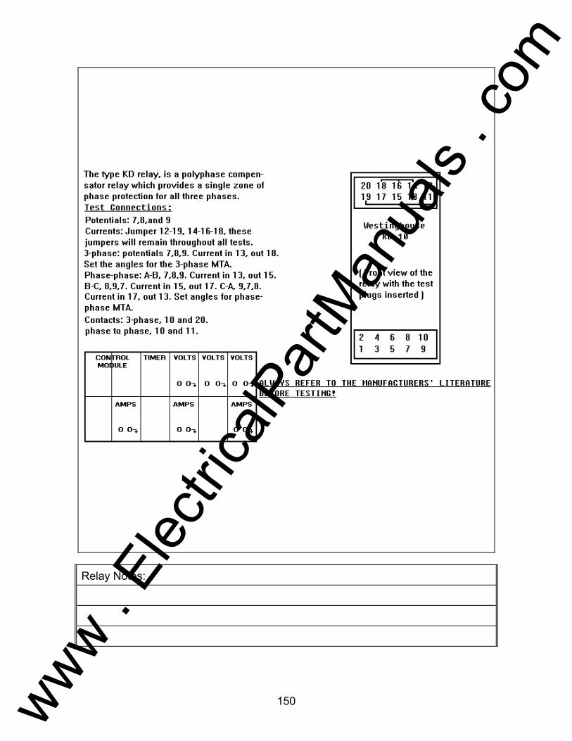
150
Relay Notes:
www . El
ectric
alPar
tMan
uals
. com
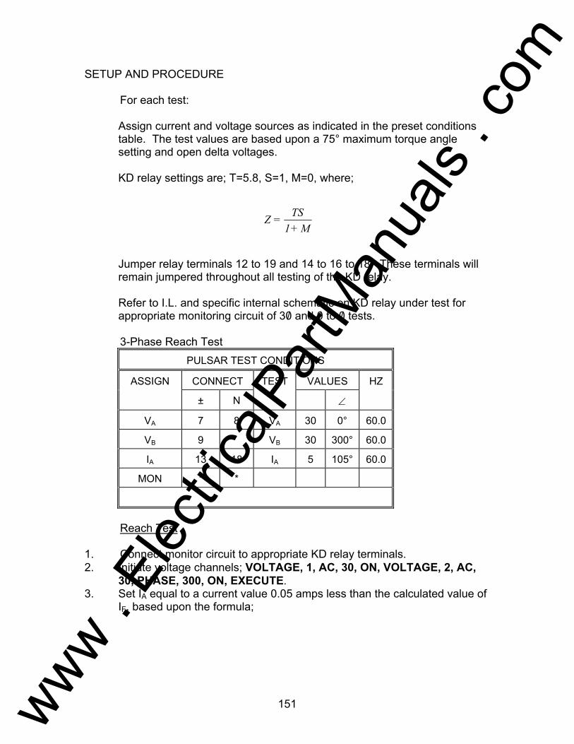
151
SETUP AND PROCEDURE For each test: Assign current and voltage sources as indicated in the preset conditions
table. The test values are based upon a 75° maximum torque angle setting and open delta voltages.
KD relay settings are; T=5.8, S=1, M=0, where;
Jumper relay terminals 12 to 19 and 14 to 16 to 18. These terminals will remain jumpered throughout all testing of the KD relay.
Refer to I.L. and specific internal schematic on KD relay under test for
appropriate monitoring circuit of 30/ and 0/ to 0/ tests. 3-Phase Reach Test
PULSAR TEST CONDITIONS
ASSIGN CONNECT TEST VALUES HZ
± N ∠
VA 7 8 VA 30 0° 60.0
VB 9 VB 30 300° 60.0
IA 13 18 IA 5 105° 60.0
MON * *
Reach Test 1. Connect monitor circuit to appropriate KD relay terminals. 2. Initiate voltage channels; VOLTAGE, 1, AC, 30, ON, VOLTAGE, 2, AC,
30, PHASE, 300, ON, EXECUTE. 3. Set IA equal to a current value 0.05 amps less than the calculated value of
IF, based upon the formula;
M+1
TS=Z
www . El
ectric
alPar
tMan
uals
. com
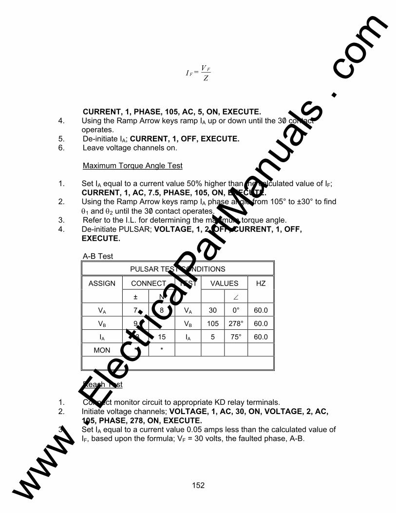
152
CURRENT, 1, PHASE, 105, AC, 5, ON, EXECUTE. 4. Using the Ramp Arrow keys ramp IA up or down until the 30/ contact
operates. 5. De-initiate IA; CURRENT, 1, OFF, EXECUTE. 6. Leave voltage channels on. Maximum Torque Angle Test 1. Set IA equal to a current value 50% higher than the calculated value of IF;
CURRENT, 1, AC, 7.5, PHASE, 105, ON, EXECUTE. 2. Using the Ramp Arrow keys ramp IA phase angle from 105° to ±30° to find
θ1 and θ2 until the 30/ contact operates. 3. Refer to the I.L. for determining the maximum torque angle. 4. De-initiate PULSAR; VOLTAGE, 1, 2, OFF, CURRENT, 1, OFF,
EXECUTE. A-B Test
PULSAR TEST CONDITIONS
ASSIGN CONNECT TEST VALUES HZ
± N ∠
VA 7 8 VA 30 0° 60.0
VB 9 VB 105 278° 60.0
IA 13 15 IA 5 75° 60.0
MON * *
Reach Test 1. Connect monitor circuit to appropriate KD relay terminals. 2. Initiate voltage channels; VOLTAGE, 1, AC, 30, ON, VOLTAGE, 2, AC,
105, PHASE, 278, ON, EXECUTE. 3. Set IA equal to a current value 0.05 amps less than the calculated value of
IF, based upon the formula; VF = 30 volts, the faulted phase, A-B.
F
FI = VZ
www . El
ectric
alPar
tMan
uals
. com

153
CURRENT, 1, PHASE, 75, AC, 5, ON, EXECUTE. 4. Using the Ramp Arrow keys ramp IA up or down until the 0/ - 0/ contact
operates. 5. De-initiate IA; CURRENT, 1, OFF, EXECUTE. 6. Leave voltage channels on. Maximum Torque Angle Test 1. Set IA equal to a current value 50% higher than the calculated value of IF;
CURRENT, 1, AC, 7.5, PHASE, 75, ON, EXECUTE. 2. Using the Ramp Arrow keys ramp IA phase angle from 75° to ±30° to find
θ1 and θ2 until the 0/ -0/ contact operates. 3. Refer to the I.L. for determining the maximum torque angle. 4. De-initiate PULSAR; VOLTAGE, 1, 2, OFF, CURRENT, 1, OFF,
EXECUTE. B-C Test
PULSAR TEST CONDITIONS
ASSIGN CONNECT TEST VALUES HZ
± N ∠
VA 9 7 VA 30 0° 60.0
VB 8 VB 105 278° 60.0
IA 15 17 IA 5 75° 60.0
MON * *
Reach Test 1. Connect monitor circuit to appropriate KD relay terminals. 2. Initiate voltage channels; VOLTAGE, 1, AC, 30, ON, VOLTAGE, 2, AC,
105, PHASE, 278, ON, EXECUTE. 3. Set IA equal to a current value 0.05 amps less than the calculated value of
IF, based upon the formula; VF = 30 volts, the faulted phase, B-C.
F
FI = VZ
www . El
ectric
alPar
tMan
uals
. com
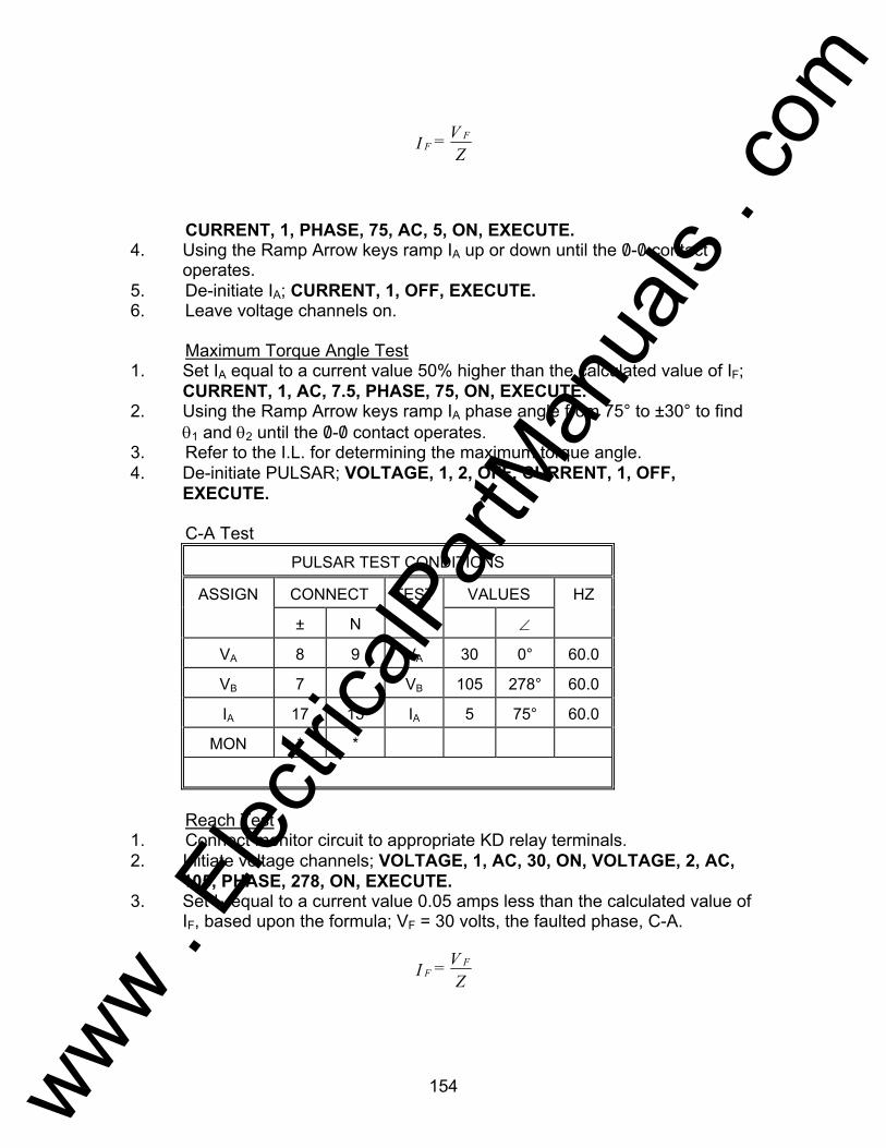
154
CURRENT, 1, PHASE, 75, AC, 5, ON, EXECUTE. 4. Using the Ramp Arrow keys ramp IA up or down until the 0/ -0/ contact
operates. 5. De-initiate IA; CURRENT, 1, OFF, EXECUTE. 6. Leave voltage channels on. Maximum Torque Angle Test 1. Set IA equal to a current value 50% higher than the calculated value of IF;
CURRENT, 1, AC, 7.5, PHASE, 75, ON, EXECUTE. 2. Using the Ramp Arrow keys ramp IA phase angle from 75° to ±30° to find
θ1 and θ2 until the 0/ -0/ contact operates. 3. Refer to the I.L. for determining the maximum torque angle. 4. De-initiate PULSAR; VOLTAGE, 1, 2, OFF, CURRENT, 1, OFF,
EXECUTE. C-A Test
PULSAR TEST CONDITIONS
ASSIGN CONNECT TEST VALUES HZ
± N ∠
VA 8 9 VA 30 0° 60.0
VB 7 VB 105 278° 60.0
IA 17 13 IA 5 75° 60.0
MON * *
Reach Test 1. Connect monitor circuit to appropriate KD relay terminals. 2. Initiate voltage channels; VOLTAGE, 1, AC, 30, ON, VOLTAGE, 2, AC,
105, PHASE, 278, ON, EXECUTE. 3. Set IA equal to a current value 0.05 amps less than the calculated value of
IF, based upon the formula; VF = 30 volts, the faulted phase, C-A.
F
FI = VZ
F
FI = VZ
www . El
ectric
alPar
tMan
uals
. com

155
CURRENT, 1, PHASE, 75, AC, 5, ON, EXECUTE. 4. Using the Ramp Arrow keys ramp IA up or down until the 0/ -0/ contact
operates. 5. De-initiate IA; CURRENT, 1, OFF, EXECUTE. 6. Leave voltage channels on. Maximum Torque Angle Test 1. Set IA equal to a current value 50% higher than the calculated value of IF;
CURRENT, 1, AC, 7.5, PHASE, 75, ON, EXECUTE. 2. Using the Ramp Arrow keys ramp IA phase angle from 75° to ±30° to find
θ1 and θ2 until the 0/ -0/ contact operates. 3. Refer to the I.L. for determining the maximum torque angle. 4. De-initiate PULSAR; VOLTAGE, 1, 2, OFF, CURRENT, 1, OFF,
EXECUTE.
www . El
ectric
alPar
tMan
uals
. com
156
Testing General Electric Type IFCV Relay AVO Multi-Amp PULSAR Date: September 30, 1993 Rev: B IEEE Device Number: 51 Function: Overcurrent with Voltage Restraint This relay test sheet describes the use of the AVO Multi-Amp PULSAR test instrument to perform the IFCV protective relay acceptance tests. Test connections to the AVO Multi-Amp PULSAR relay test set and manufacturer recommended relay settings are included. References: Manufacturer's Reference GEK-49946 Literature Test Equipment PULSAR Operating Manual Instructional Material Description of Relay The IFCV is an overcurrent relay with voltage restraint. The IFCV is primarily used as system fault backup protection at the generator or source of fault current to minimize the damage resulting from a short circuit if the primary protective devices should fail to operate. PRECAUTIONS ***************WARNING************** Dangerous and potentially fatal voltage can be developed across the output terminals of the PULSAR relay test set, refer to the PULSAR operation manual for further instructions. Always turn the outputs OFF before connecting, removing or touching any output terminal or test lead, use extreme caution when turning on or using the PULSAR relay test set. ALWAYS TEST THIS RELAY IN ITS CASE.
www . El
ectric
alPar
tMan
uals
. com
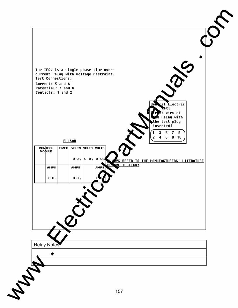
157
Relay Notes:
www . El
ectric
alPar
tMan
uals
. com

158
SETUP AND PROCEDURE For each test: Assign current and voltage sources as indicated in the preset conditions
table.
PULSAR TEST CONDITIONS
ASSIGN CONNECT TEST VALUES HZ
± N ∠
VA 7 8 VA 120 0° 60.0
IA 5 6 IA 2 0° 60.0
MON 1 2
MINIMUM PICKUP TEST 1. Set VA equal to restraint voltage and initiate VA ; VOLTAGE, 1, AC,120,
ON, EXECUTE. 2. Set IA equal to tap value; CURRENT, 1, AC, 2, ON, EXECUTE. Note that
disk should be slowly moving (creep). 3. Using the Ramp Arrow keys ramp IA up and down to determine minimum
pickup value. 4. Record the minimum pickup value. 5. De-initiate VA and IA; VOLTAGE, 1, CURRENT, 1, OFF, EXECUTE. TIMING TEST 1. Move monitor circuit to timer stop gate. 2. Set IA equal to fault current level(s) i.e., 2x tap, and output to turn off when
relay trips; CURRENT, 1, AC, 4 , ON, Shift, A-OFF, ON, TIMER START, EXECUTE.
3. Upon contact closure of IFCV contacts, record the timing value. 4. Repeat tests as necessary for other multiples of tap, for example; CURRENT, 1, AC, 6, ON, TIMER START, EXECUTE. CURRENT, 1, AC, 8, ON, TIMER START, EXECUTE. CURRENT, 1, AC, 10, ON, TIMER START, EXECUTE. INSTANTANEOUS TEST 1. Move monitor circuit to terminals 1 and 3.
www . El
ectric
alPar
tMan
uals
. com

159
2. Set IA equal to 20A ; CURRENT, 1, AC, 20, Shift, A-OFF, ON, EXECUTE. 3. Turn IA ON; CURRENT, 1, ON, EXECUTE. Pulse IA up or down until main
trip contacts pickup, using the incremental steps of 1A and the OFF, EXECUTE, ON, EXECUTE sequential commands. When relay trips, output will automatically turn off.
4. Record pickup value.
www . El
ectric
alPar
tMan
uals
. com
160
Testing Westinghouse Type KLF Relay AVO Multi-Amp PULSAR Date: September 30, 1993 Rev: B IEEE Device Number: 40 Function: Loss of Field This relay test sheet describes the use of the AVO Multi-Amp PULSAR test instrument to perform the KLF protective relays acceptance tests. Test connections to the AVO Multi-Amp PULSAR relay test set and manufacturer recommended relay settings are included. References: Manufacturer's Reference I.L. 41-748N Literature Test Equipment PULSAR Operating Manual Instructional Material Description of Relay The KLF relay is designed by Westinghouse Electric Corporation (ABB). The KLF is a single-phase relay connected to the ac side of asynchronous machine and contains three units connected so that the operation of two units sounds an alarm, warning of a low excitation condition. If the third unit operates the trip circuit is energized. The relay consists of two-air gaped compensators. two tapped auto transformers, one reactor, on cylinder type distance unit, directional unit with adjustable reactor, an under voltage unit with adjustable resistor, telephone relay and an indicating contactor switch. PRECAUTIONS ***************WARNING************** Dangerous and potentially fatal voltage can be developed across the output terminals of the PULSAR relay test set, refer to the PULSAR operation manual for further instructions. Always turn the source output OFF before connecting, removing or touching any output terminal or test lead, use extreme caution when turning on or using the PULSAR relay test set. ALWAYS TEST THIS RELAY IN ITS CASE.
www . El
ectric
alPar
tMan
uals
. com

161
Relay Notes:
www . El
ectric
alPar
tMan
uals
. com

162
SETUP AND PROCEDURE For each test: Assign current and voltage sources as indicated in the preset conditions
table. Make the following tap settings to the KLF relay: TA = 11.5 TC = 2.55 SA = 2 SC = 1 MA = -.03 MC = -.09 TC link in middle block should be set for +TC direction. This setting
corresponds to a ZA = 23.7Ω and ZC = 2.80Ω. Distance Unit (Z) Pick-up Test
PULSAR TEST CONDITIONS
ASSIGN CONNECT TEST VALUES HZ
± N ∠
VA 5 4 VA 80 0° 60.0
IA 9 8 IA 2 90° 60.0
MON 10 1
NOTE: Block Directional Contacts closed while testing Distance Unit. 1. Set VA for 80 volts and initiate; VOLTAGE, 1, AC, 80, ON, EXECUTE. 2. Set IA for 2.0 amps and initiate; CURRENT, 1, PHASE, 90, AC, 2, ON,
EXECUTE. 3. Using the Ramp Arrow keys and ramp the current up until the relay
operates at approximately ±3% of 2.25 amps. 4. De-initiate PULSAR; VOLTAGE, 1, CURRENT, 1, OFF, EXECUTE.
www . El
ectric
alPar
tMan
uals
. com

163
PULSAR TEST CONDITIONS
ASSIGN CONNECT TEST VALUES HZ
± N ∠
VA 5 4 VA 80 0° 60.0
IA 9 8 IA 9 270° 60.0
IB 9 8 IB 9 270° 60.0
MON 10 1
NOTE: DUE TO BURDEN OF RELAY, IA and IB must be paralleled to do
test. 1. Set VA for 80 volts and initiate; VOLTAGE, 1, AC, 80, ON, EXECUTE. 2. Set IA and IB for 9 amps and initiate; CURRENT, 1, 2, PHASE, 270, AC, 9,
ON, EXECUTE. 3. Using the Ramp Arrow keys, ramp the current up or down until the relay
operates at approximately ±3% of 19.0 amps. 4. De-initiate PULSAR; VOLTAGE, 1, CURRENT, 1, OFF, EXECUTE. 5. Remove blocking material from Directional Unit. Directional Unit (D) Pick-up Test
PULSAR TEST CONDITIONS
ASSIGN CONNECT TEST VALUES HZ
± N ∠
VA 6 7 VA 1 0° 60.0
IA 9 8 IA 5 347° 60.0
MON 10 1
NOTE: Block Distance Unit contacts closed. 1. Set VA to 1 volt and initiate; VOLTAGE, 1, AC, 1, ON, EXECUTE. 2. Set IA phase angle to 347° and initiate, where current leads the voltage by
13°; CURRENT, 1, AC, 5, PHASE, 347, ON, EXECUTE. The relay contacts should be closed. This is the maximum torque angle position.
3. Raise the voltage of VA to 120 volts; VOLTAGE, 1, AC, 120, EXECUTE. Using the following keystrokes; CURRENT, 1, PHASE, and using the
www . El
ectric
alPar
tMan
uals
. com
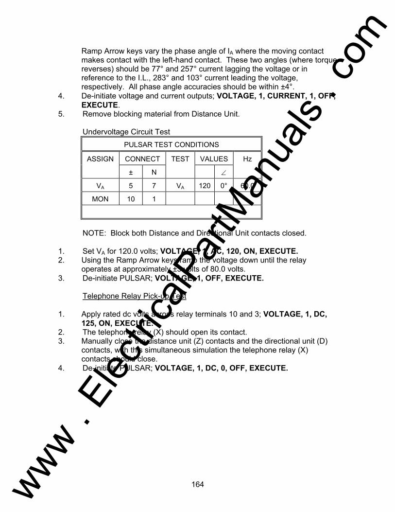
164
Ramp Arrow keys vary the phase angle of IA where the moving contact makes contact with the left-hand contact. These two angles (where torque reverses) should be 77° and 257° current lagging the voltage or in reference to the I.L., 283° and 103° current leading the voltage, respectively. All phase angle accuracies should be within ±4°.
4. De-initiate voltage and current outputs; VOLTAGE, 1, CURRENT, 1, OFF, EXECUTE.
5. Remove blocking material from Distance Unit. Undervoltage Circuit Test
PULSAR TEST CONDITIONS
ASSIGN CONNECT TEST VALUES Hz
± N ∠
VA 5 7 VA 120 0° 60.0
MON 10 1
NOTE: Block both Distance and Directional Unit contacts closed. 1. Set VA for 120.0 volts; VOLTAGE, 1, AC, 120, ON, EXECUTE. 2. Using the Ramp Arrow keys ramp the voltage down until the relay
operates at approximately ±3 volts of 80.0 volts. 3. De-initiate PULSAR; VOLTAGE, 1, OFF, EXECUTE. Telephone Relay Pick-up Test 1. Apply rated dc volts across relay terminals 10 and 3; VOLTAGE, 1, DC,
125, ON, EXECUTE. 2. The telephone relay (X) should open its contact. 3. Manually close the distance unit (Z) contacts and the directional unit (D)
contacts, with this simultaneous simulation the telephone relay (X) contacts should close.
4. De-initiate PULSAR; VOLTAGE, 1, DC, 0, OFF, EXECUTE.
www . El
ectric
alPar
tMan
uals
. com

165
Testing General Electric Type PJC Relay AVO Multi-Amp PULSAR Date: September 30, 1993 Rev: A IEEE Device Number: 51 Function: Overcurrent Relay This relay test sheet describes the use of the AVO Multi-Amp PULSAR test instrument to perform the PJC protective relay acceptance tests. Test connections to the AVO Multi-Amp PULSAR relay test set and manufacturer recommended relay settings are included. References: Manufacturer's Reference GEK-27893B Literature Test Equipment PULSAR Operating Manual Instructional Material Description of Relay The PJC32 relays are commonly used for instantaneous overcurrent protection of feeder circuits and for motors in conjunction with time-delay relays. PRECAUTIONS ***************WARNING************** Dangerous and potentially fatal voltage can be developed across the output terminals of the PULSAR relay test set, refer to the PULSAR operation manual for further instructions. Always turn the outputs OFF before connecting, removing or touching any output terminal or test lead, use extreme caution when turning on or using the PULSAR relay test set. ALWAYS TEST THIS RELAY IN ITS CASE.
www . El
ectric
alPar
tMan
uals
. com
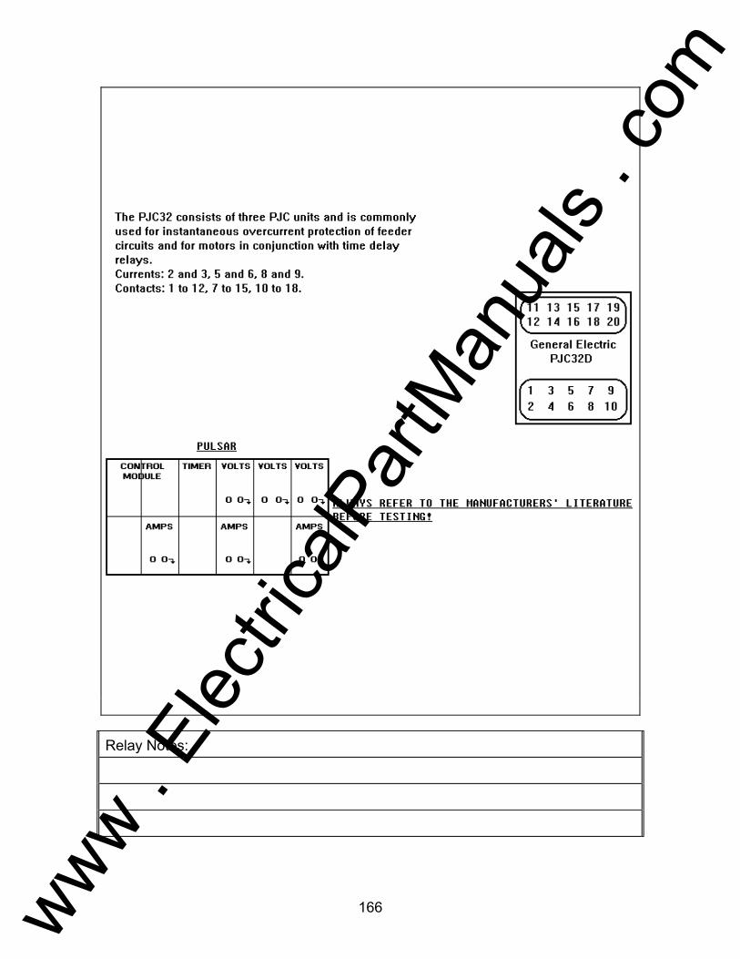
166
Relay Notes:
www . El
ectric
alPar
tMan
uals
. com

167
SET UP AND PROCEDURE For each test: Assign current sources as indicated in the preset conditions table. Execute the test as defined in the PULSAR CONDITIONS table.
PULSAR TEST CONDITIONS
ASSIGN CONNECT TEST VALUES HZ
± N ∠
IA 2 3 IA * 0° 60.0
IB 5 6 IB * 0° 60.0
IC 8 9 IC * 0o 60.0
MON * *
ALWAYS REFER TO THE MANUFACTURERS' LITERATURE BEFORE TESTING! PICKUP TEST 1. Connect the monitor circuit to the appropriate relay contacts. 2. Set IA to the minimum pickup value using the following keystrokes;
CURRENT, 1, AC, (*), EXECUTE. 3. Initiate the PULSAR; CURRENT, 1, ON, EXECUTE. Using the
appropriate Ramp Arrow keys ,, ramp IA to find the pickup. 4. Record the pickup value, refer to the PJC32 I.L. for any adjustment. 5. Turn IA OFF, whenever an adjustment is required or the test is completed.
CURRENT, 1, OFF, EXECUTE. TIMING TEST 1. Move the monitor circuit to timer stop gate, (T2). 2. Set IA to the pickup value, using the following keystrokes; CURRENT, 1,
AC, (*), EXECUTE. 3. Set the output to turn OFF when the relay trips, using the following
keystrokes; Shift, A-OFF, ON, EXECUTE. 4. Initiate IA and start the Timer using the following keystrokes; ON, TIMER,
START, EXECUTE. 5. Record the timing pickup value. Repeat the test if necessary
www . El
ectric
alPar
tMan
uals
. com

168
6. Reset Auto-Off, using the following keystrokes; Shift, A-OFF, OFF, EXECUTE.
www . El
ectric
alPar
tMan
uals
. com

169
Testing General Electric Type PJV Rely AVO Multi-Amp PULSAR Date: September 30, 1993 Rev: A IEEE Device Number: 29/59 Function: Under/over voltage Relay This relay test sheet describes the use of the AVO Multi-Amp PULSAR test instrument to perform the PJV protective relay acceptance tests. Test connections to the AVO Multi-Amp PULSAR relay test set and manufacturer recommended relay settings are included. References: Manufacturer's Reference GEI-28802 Literature Test Equipment PULSAR Operating Manual Instructional Material Description of Relay The PJV11L and PJV12B relays are single frequency AC or DC operated devices. These relays are single element high speed plunger type voltage relays. PRECAUTIONS ***************WARNING************** Dangerous and potentially fatal voltage can be developed across the output terminals of the PULSAR relay test set, refer to the PULSAR operation manual for further instructions. Always turn the outputs OFF before connecting, removing or touching any output terminal or test lead, use extreme caution when turning on or using the PULSAR relay test set. ALWAYS TEST THIS RELAY IN ITS CASE.
www . El
ectric
alPar
tMan
uals
. com

170
Relay Notes:
www . El
ectric
alPar
tMan
uals
. com

171
SET UP AND PROCEDURE For each test: Assign voltage sources as indicated in the preset conditions table. Execute the test as defined in the PULSAR CONDITIONS table.
PULSAR TEST CONDITIONS
ASSIGN CONNECT TEST VALUES HZ
± N ∠
VA 5 6 VA * 0o 60.0
60.0
MON 1 2
ALWAYS REFER TO THE MANUFACTURERS' LITERATURE BEFORE TESTING! NOTE: If output voltage required exceeds 300 volts, see Operating
Procedures, Section 1.3, Voltage Sources - Outputs Summed Together. PICKUP TEST 1. Connect the monitor circuit to the appropriate relay contacts. 2. Set VA to the expected pickup value using the following keystrokes;
VOLTAGE, 1, AC, (*), EXECUTE. NOTE: If DC relay substitute "DC" for "AC".
3. Initiate the PULSAR; VOLTAGE, 1, ON, EXECUTE. Using the appropriate Ramp Arrow keys ,, ramp VA to find the pickup.
4. Record the pickup value, refer to the PJV I.L. for any adjustment. 5. Turn VA OFF, whenever an adjustment is required or the test is
completed. VOLTAGE, 1, OFF, EXECUTE. TIMING TEST 1. Move the monitor circuit to the timer stop gate, (T2). 2. Set VA to the pickup value using the following keystrokes; VOLTAGE, 1,
AC, (*), EXECUTE. NOTE: If DC relay, substitute "DC" for "AC". 3. Set the output to turn OFF when the relay trips using the following
keystrokes; Shift, A-OFF, ON, EXECUTE. 4. Initiate VA and start the Timer using the following keystrokes; ON, TIMER,
START, EXECUTE.
www . El
ectric
alPar
tMan
uals
. com

172
5. Record the timing pickup value. Repeat the test if necessary. 6. Reset A-OFF, using the following keystrokes; Shift, A-OFF, OFF,
EXECUTE.
www . El
ectric
alPar
tMan
uals
. com

173
Testing Basler Type PRS-170 Relay AVO Multi-Amp PULSAR Date: September 30, 1993 Rev: A IEEE Device Number: 25A Function: Auto-Synchronizing Relay This relay test sheet describes the use of the AVO Multi-Amp PULSAR test instrument to perform the Basler Model PRS-170 Auto-Synchronizing relay acceptance tests. Test connections to the AVO Multi-Amp PULSAR relay test set and manufacturer recommended relay settings are included. References: Manufacturer's Reference A90 95100 990 Literature Test Equipment PULSAR Operating Manual Instructional Material Description of Relay The PRS-170 is a auto-synchronizing relay, with add-on modules for voltage and speed control. The synchronizer will automatically adjust generator voltage and frequency until the generator and bus are within preselected values. Then if the voltages and slip frequency are within limits, it will automatically close the breaker. PRECAUTIONS ***************WARNING************** Dangerous and potentially fatal voltage can be developed across the output terminals of the PULSAR relay test set, refer to the PULSAR operation manual for further instructions. Always turn the outputs OFF before connecting, removing or touching any output terminal or test lead, use extreme caution when turning on or using the PULSAR relay test set. ALWAYS TEST THIS RELAY IN ITS CASE.
www . El
ectric
alPar
tMan
uals
. com

174
Relay Notes:
www . El
ectric
alPar
tMan
uals
. com

175
SETUP AND PROCEDURE For following tests, assign voltage sources as indicated in the preset
conditions table below.
PULSAR TEST CONDITIONS
ASSIGN CONNECT TEST VALUES HZ
± N ∠
VA 3 4 VA 120 0° 60.0
VB 5 6 VB * 0° 60.0
MON @ @
VA = BUS Voltage and VB = GENERATOR Voltage
(@) MONITOR connections vary for each individual test. See test
procedure for connections. (*) VB amplitudes vary depending on test. NOTE: Apply AC logic voltage to relay terminals 1 and 2 for all tests. LOW VOLTAGE PICKUP TEST (A1 OPTION ONLY) 1. Set VA and VB equal to rated voltage and turn on using the following
keystrokes; VOLTAGE, 1, 2, AC, 120, ON, EXECUTE. Connect MONITOR leads to relay terminals 19 and 20.
2. Ramp VB down using the appropriate RAMP key until the relay's LOW VOLTAGE LED lights and contacts pickup making the Timer MONITOR LED light. To ramp voltage down use the following keystrokes; VOLTAGE, 2, AC, and press the appropriate RAMP key.
3. Record the low voltage pickup value (adjustable between ± 0.5 to ± 4.5% difference between VA and VB).
4. Return VB to rated voltage (use the RAMP key), and proceed to the next test.
NOTE: For A2 option, undervoltage control, use same procedure except pickup value is a set voltage amplitude not a % difference.
HIGH VOLTAGE PICKUP TEST (A1 OPTION ONLY) 1. If VA and VB are not set from previous test, set VA and VB equal to rated
voltage and turn on using the following keystrokes; VOLTAGE, 1, 2, AC, 120, ON, EXECUTE. Move MONITOR leads to relay terminals 22 and 23.
www . El
ectric
alPar
tMan
uals
. com

176
2. Ramp VB up using the appropriate RAMP key until the relay's HIGH VOLTAGE LED lights and contacts pickup making the Timer MONITOR LED light. To ramp voltage up use the following keystrokes; VOLTAGE, 2, AC, and press the appropriate RAMP key.
3. Record the high voltage pickup value (adjustable between ± 0.5 to ± 4.5% difference between VA and VB).
4. Return VB to rated voltage (use the RAMP key), and proceed to the next test.
NOTE: For A2 option, overvoltage control, use same procedure except pickup value is a set voltage amplitude not a % difference.
LOW FREQUENCY/HIGHER SPEED TEST (F1 OPTION ONLY) 1. Set VA and VB equal to rated voltage and turn on using the following
keystrokes; VOLTAGE, 1, 2, AC, 120, ON, EXECUTE. Move MONITOR leads to relay terminals 13 and 14.
2. Ramp VB frequency down using the appropriate RAMP key until the relay's LOW FREQUENCY LED lights and contacts pickup making the Timer MONITOR LED light. To ramp frequency down use the following keystrokes; VOLTAGE, 2, FREQ, and press the appropriate RAMP key.
3. Record the frequency pickup value and that the control contacts closed. 4. Return VB to system frequency (use the RAMP key), and proceed to the
next test. HIGH FREQUENCY/LOWER SPEED TEST (F1 OPTION ONLY) 1. If VA and VB are not set from previous test, set VA and VB equal to rated
voltage and turn on using the following keystrokes; VOLTAGE, 1, 2, AC, 120, ON, EXECUTE. Move MONITOR leads to relay terminals 16 and 17.
2. Ramp VB frequency up using the appropriate RAMP key until the relay's
HIGH FREQUENCY LED lights and contacts pickup making the Timer MONITOR LED light. To ramp frequency up use the following keystrokes; VOLTAGE, 2, FREQ, and press the appropriate RAMP key.
3. Record the frequency pickup value and that the control contacts closed. 4. Return VB to rated frequency (use the RAMP key), and proceed to the
next test.
www . El
ectric
alPar
tMan
uals
. com

177
SLIP FREQUENCY PICKUP TEST 1. If VA and VB are not set from previous test, set VA and VB equal to rated
voltage and turn on using the following keystrokes; VOLTAGE, 1, 2, AC, 120, ON, EXECUTE. Move MONITOR leads to the "breaker close" relay terminals 11 and 12.
2. Ramp VB frequency up using the appropriate RAMP key until the relay's SYNC LED lights and contacts pickup making the Timer MONITOR LED light. To ramp frequency up use the following keystrokes; VOLTAGE, 2, FREQ, and press the appropriate RAMP key. Wait an appropriate time (depending on slip frequency) between increments to allow the relay time to operate. Continue slowly incrementing frequency up until the SYNC and MONITOR LED's no longer light.
3. Record the maximum slip frequency pickup value as the last slip value where the relay would close every time.
4. Return VB to rated frequency (use the RAMP key), and proceed to the next test.
ADVANCE TIMING TEST 1. Move monitor circuit to timer start gate, (T1). 2. Set VA to rated voltage by using the following keystrokes; VOLTAGE, 1,
AC, 120, ON, EXECUTE. 3. Set VB to an appropriate output voltage and slip frequency, but do not turn
on yet. For example use the following keystrokes to set a slip of 60.1 Hz; VOLTAGE, 2, AC, 120, FREQ., 60.100, EXECUTE. VB DEGREES display should have dashed lines (the dashes will reset to zero's when the test is executed).
4. Set VA and VB to turn on and the Timer to Stop On Synchronization by
using the following keystrokes, VOLTAGE, 1, 2, Shift, TSOS, ON, EXECUTE. VB will turn on in phase with VA, but will slip out of phase at the selected slip frequency. At the advance angle the relay contacts will close, thus starting the timer, when the two voltages slip into phase the Timer will stop and the outputs will turn off.
5. Read and record time. The time indicated should be the advance time setting of the relay.
www . El
ectric
alPar
tMan
uals
. com

178
Testing General Electric Type PVD AVO Multi-Amp PULSAR Date: September 30, 1993 Rev: A IEEE Device Number: 87 Function: Transformer Differential This relay test sheet describes the use of the AVO Multi-Amp PULSAR test instrument to perform the PVD protective relay acceptance tests. Test connections to the AVO Multi-Amp PULSAR relay test set and manufacturer recommended relay settings are included. References: Manufacturer's Reference GEK-45405B Literature Test Equipment PULSAR Operating Manual Instructional Material Description of Relay The PVD21 relays are single phase, high speed, high impedance, voltage operated relays that are designed to provide protection in bus differential schemes when used in conjunction with suitable current transformers. PRECAUTIONS ***************WARNING************** Dangerous and potentially fatal voltage can be developed across the output terminals of the PULSAR relay test set, refer to the PULSAR operation manual for further instructions. Always turn the outputs OFF before connecting, removing or touching any output terminal or test lead, use extreme caution when turning on or using the PULSAR relay test set. ALWAYS TEST THIS RELAY IN ITS CASE.
www . El
ectric
alPar
tMan
uals
. com

179
Relay Notes:
www . El
ectric
alPar
tMan
uals
. com
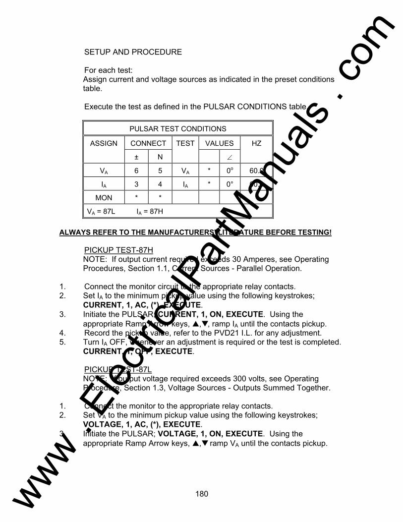
180
SETUP AND PROCEDURE For each test: Assign current and voltage sources as indicated in the preset conditions
table. Execute the test as defined in the PULSAR CONDITIONS table.
PULSAR TEST CONDITIONS
ASSIGN CONNECT TEST VALUES HZ
± N ∠
VA 6 5 VA * 0o 60.0
IA 3 4 IA * 0° 60.0
MON * *
VA = 87L IA = 87H
ALWAYS REFER TO THE MANUFACTURERS' LITERATURE BEFORE TESTING! PICKUP TEST-87H NOTE: If output current required exceeds 30 Amperes, see Operating
Procedures, Section 1.1, Current Sources - Parallel Operation. 1. Connect the monitor circuit to the appropriate relay contacts. 2. Set IA to the minimum pickup value using the following keystrokes;
CURRENT, 1, AC, (*), EXECUTE. 3. Initiate the PULSAR; CURRENT, 1, ON, EXECUTE. Using the
appropriate Ramp Arrow keys, ,, ramp IA until the contacts pickup. 4. Record the pickup value, refer to the PVD21 I.L. for any adjustment. 5. Turn IA OFF, whenever an adjustment is required or the test is completed.
CURRENT, 1, OFF, EXECUTE. PICKUP TEST-87L NOTE: If output voltage required exceeds 300 volts, see Operating
Procedure, Section 1.3, Voltage Sources - Outputs Summed Together. 1. Connect the monitor to the appropriate relay contacts. 2. Set VA to the minimum pickup value using the following keystrokes;
VOLTAGE, 1, AC, (*), EXECUTE. 3. Initiate the PULSAR; VOLTAGE, 1, ON, EXECUTE. Using the
appropriate Ramp Arrow keys, , ramp VA until the contacts pickup.
www . El
ectric
alPar
tMan
uals
. com

181
4. Record the pickup value, refer to the PVD21 I.L. for any adjustment. 5. Turn VA OFF, whenever an adjustment is required or the test is
completed. VOLTAGE, 1, OFF, EXECUTE.
www . El
ectric
alPar
tMan
uals
. com

Test Procedures - 182
www . El
ectric
alPar
tMan
uals
. com


