INSTRUCTION MANUAL - Prom Electricprom-electric.ru/media/KDGC-Control-Panel-Manual.pdfINSTRUCTION...
92
Publication: 9 3055 00 990 Revision: C 04/99 INSTRUCTION MANUAL for DGC-2000 DIGITAL GENSET CONTROLLER Lamp Test Silence Alarm Toggle Phase Auto Off Run Toggle Display Previous Enter Select Scroll Lower Scroll Raise Run Time Voltage Battery Temperature Coolant Pressure Oil Voltage Generator Amps Generator Phase Generator Frequency Generator Controller Genset Digital Basler DGC-2000 Supplying Load Alarm Auto Not In
Transcript of INSTRUCTION MANUAL - Prom Electricprom-electric.ru/media/KDGC-Control-Panel-Manual.pdfINSTRUCTION...

Publication: 9 3055 00 990Revision: C 04/99
INSTRUCTION MANUALfor
DGC-2000DIGITAL GENSET
CONTROLLER
L a m p
TestSi lence
Alarm
Togg le
Phase
AutoOffRun
Toggle
DisplayPrevious
Enter
Select
Scrol l
Lower
Scrol l
Raise
R u n
TimeVol tage
Battery
Temperature
Coolant
Pressure
Oil
Vol tage
Generator
A m p s
Generator
Phase
Generator
Frequency
Generator
ControllerGensetDigital
Bas
ler
DGC-2000
Supply ing
LoadAlarmAuto
Not In

DGC-2000 INTRODUCTION i
INTRODUCTION
This manual provides information concerning the installation and operation of the DGC-2000 DigitalGenset Controller. To accomplish this, the following is provided.
• General Information• Specifications• Functional Description• Installation Information• Communication Software Description• Testing Procedures
WARNING!TO AVOID PERSONAL INJURY OR EQUIPMENT DAMAGE, ONLY QUALIFIEDPERSONNEL SHOULD PERFORM THE PROCEDURES PRESENTED IN THISMANUAL.

ii DGC-2000 INTRODUCTION
First Printing: November 1997
Printed in USA
© 1997, 1998, 1999 Basler Electric Co., Highland, IL 62249
April 1999
CONFIDENTIAL INFORMATIONOF BASLER ELECTRIC COMPANY, HIGHLAND, IL. IT IS LOANED FORCONFIDENTIAL USE, SUBJECT TO RETURN ON REQUEST, AND WITH THEMUTUAL UNDERSTANDING THAT IT WILL NOT BE USED IN ANY MANNERDETRIMENTAL TO THE INTEREST OF BASLER ELECTRIC COMPANY.
It is not the intention of this manual to cover all details and variations in equipment, nordoes this manual provide data for every possible contingency regarding installation oroperation. The availability and design of all features and options are subject tomodification without notice. Should further information be required, contact Basler ElectricCompany, Highland, Illinois.
BASLER ELECTRICROUTE 143, BOX 269
HIGHLAND, IL 62249 USAhttp://www.basler.com, [email protected]
PHONE 618-654-2341 FAX 618-654-2351
DGC-2000 INTRODUCTION iii
CONTENTS
SECTION 1 GENERAL INFORMATION ................................................................................................ 1-1
Description .......................................................................................................................... 1-1Features .............................................................................................................................. 1-1Functions............................................................................................................................. 1-1Outputs................................................................................................................................ 1-1Specifications ...................................................................................................................... 1-2
SECTION 2 HUMAN-MACHINE INTERFACE (Controls And Indicators)........................................... 2-1
General................................................................................................................................ 2-1Front Panel Display ............................................................................................................. 2-1DGC-2000 Connections ...................................................................................................... 2-2
SECTION 3 FUNCTIONAL DESCRIPTION ........................................................................................... 3-1
General................................................................................................................................ 3-1Inputs................................................................................................................................... 3-2
Battery Operating Voltage ............................................................................................ 3-2Contact Sensing Inputs................................................................................................. 3-2Sending Unit Inputs....................................................................................................... 3-3Speed Signal Inputs...................................................................................................... 3-3Voltage Inputs ............................................................................................................... 3-3Current Inputs ............................................................................................................... 3-3Serial Communications Input ........................................................................................ 3-3
Microprocessor.................................................................................................................... 3-3Formulas....................................................................................................................... 3-3Related circuits ............................................................................................................. 3-4
Outputs................................................................................................................................ 3-4Software .............................................................................................................................. 3-5
Display Modes .............................................................................................................. 3-5Normal Mode ................................................................................................................ 3-5Menu Mode................................................................................................................... 3-5Exiting Menu Mode ..................................................................................................... 3-15Modifying Setpoints..................................................................................................... 3-16Alternate Display Mode............................................................................................... 3-17
Factory Key Code Setting ................................................................................................. 3-17Allowable Key Code Pushbuttons ..................................................................................... 3-18Parameters And Default Settings ...................................................................................... 3-18
Front Panel Adjustable Parameters............................................................................ 3-18All Parameters ............................................................................................................ 3-18
SECTION 4 INSTALLATION.................................................................................................................. 4-1
General................................................................................................................................ 4-1Hardware............................................................................................................................. 4-1Mounting.............................................................................................................................. 4-1Connections ........................................................................................................................ 4-3Communication Connectors And Settings........................................................................... 4-7
RS-232 Connector ........................................................................................................ 4-7Communication Settings............................................................................................... 4-7

iv DGC-2000 INTRODUCTION
CONTENTS - Continued
SECTION 5 TESTING............................................................................................................................. 5-1
Introduction.......................................................................................................................... 5-1Equipment Required............................................................................................................ 5-1Initial Test Procedure .......................................................................................................... 5-1Metering Test Procedure..................................................................................................... 5-3
Metering Battery And Generator Voltages.................................................................... 5-3Metering Bus Voltages.................................................................................................. 5-5Metering Generator Current.......................................................................................... 5-5Oil Pressure .................................................................................................................. 5-5Coolant Temperature.................................................................................................... 5-5Percent Fuel Level ........................................................................................................ 5-5Engine Speed (RPM) .................................................................................................... 5-5Generator Power Factor ............................................................................................... 5-6Generator kW And kVA ................................................................................................ 5-6
Cranking Test Procedures................................................................................................... 5-6Crank Cycle .................................................................................................................. 5-6Running......................................................................................................................... 5-7
Protective Functions............................................................................................................ 5-7Overcrank ..................................................................................................................... 5-7Overspeed .................................................................................................................... 5-7Low Oil Pressure .......................................................................................................... 5-7High Coolant Temperature............................................................................................ 5-8Air Damper.................................................................................................................... 5-8Emergency Stop ........................................................................................................... 5-8Low Coolant Level ........................................................................................................ 5-9
SECTION 6 MODBUS™ COMMUNICATIONS...................................................................................... 6-1
General................................................................................................................................ 6-1Interface........................................................................................................................ 6-1Applications................................................................................................................... 6-1
Introduction To Modbus™ Protocol..................................................................................... 6-1DGC-2000 MODBUS™ Protocol......................................................................................... 6-1
Message Structure........................................................................................................ 6-2Device Address Field.................................................................................................... 6-2Function Code Field...................................................................................................... 6-2Data Block Field............................................................................................................ 6-2Error Check Field.......................................................................................................... 6-2
Serial Transmission Details................................................................................................. 6-2Message Framing And Timing Considerations ................................................................... 6-3Error Handling And Exception Responses .......................................................................... 6-3Communications Hardware Requirements.......................................................................... 6-3Detailed Message Query And Response ............................................................................ 6-3
Read Holding Registers Query ..................................................................................... 6-3Read Holding Registers Response............................................................................... 6-4Return Query Data........................................................................................................ 6-4Return Query ................................................................................................................ 6-5Return Response.......................................................................................................... 6-5Preset Multiple Register Query..................................................................................... 6-6Preset Multiple Register Response .............................................................................. 6-6
Changing The Logon Password .......................................................................................... 6-7Data Formats....................................................................................................................... 6-7
Double Precision Data Format...................................................................................... 6-7Triple Precision Data Format ........................................................................................ 6-7Error Check................................................................................................................... 6-8

DGC-2000 INTRODUCTION v
Settings Source Register (40081)................................................................................. 6-8Saving Settings Register (40082) ................................................................................. 6-8
CONTENTS - Continued
SECTION 6 MODBUS™ COMMUNICATIONS - Continued
Mapping Registers Into Modicon Address Space ............................................................... 6-8Conventions.................................................................................................................. 6-8Register Table .............................................................................................................. 6-9
SECTION 7 DGC-2000 WINDOWS® SOFTWARE................................................................................. 7-1
General................................................................................................................................ 7-1Installation ........................................................................................................................... 7-1
Operating Requirements............................................................................................... 7-1Installing the Program on Your PC with Windows® 95 .................................................. 7-1Installing the Program on Your PC with Windows® 3.1 ................................................. 7-1Configuring the System ................................................................................................ 7-1
Initializing Communications with the DGC 2000 Windows Software................................... 7-1Changing the Programs Communication Parameters......................................................... 7-3Changing Logon Passwords ............................................................................................... 7-4Remote Start and Stop of Generator................................................................................... 7-4Changing Settings ............................................................................................................... 7-5Menus.................................................................................................................................. 7-5
File Menu ...................................................................................................................... 7-5Communications Menu ................................................................................................. 7-5Screens Menu............................................................................................................... 7-6Configure Menu ............................................................................................................ 7-6Help Menu..................................................................................................................... 7-6
Settings Definitions.............................................................................................................. 7-6Sensing Transformers Settings .................................................................................... 7-7Pre-Alarm Settings-Low Fuel-Low Cool-Batt. OverVolt. ............................................... 7-8Pre-Alarm Settings-Maint. Inter.-Eng. kW Overload-Hi Cool ........................................ 7-9Pre-Alarm Settings-Low Oil-Low Batt. Volt- Weak Batt Volt ....................................... 7-10Pre-Alarm Settings-Audible-Battery Charger.............................................................. 7-11Alarm Settings-Hi Cool Temp-Low Oil Press.............................................................. 7-12Alarm Settings-Overspeed-Sender Failure................................................................. 7-13Crank Settings ............................................................................................................ 7-14System Settings.......................................................................................................... 7-15Metering...................................................................................................................... 7-16Top Portion of the Screen........................................................................................... 7-17
SECTION 8 MANUAL CHANGE INFORMATION.................................................................................. 8-1
Changes .............................................................................................................................. 8-1
APPENDIX A DGC-2000 SETTINGS RECORD
Introduction..........................................................................................................................A-1DGC-2000 Settings Record.................................................................................................A-2

DGC-2000 GENERAL INFORMATION 1-1
SECTION 1 • GENERAL INFORMATION
DESCRIPTION
DGC-2000 Digital Genset Controllers use microprocessor based technology to provide integrated engine-generator set control, protection, and metering in a single package. Microprocessor based technologyallows for exact measurement, set point adjustment, and timing functions. The DGC-2000 allows for quickand simple operation from the front panel or through serial link communications. Communications usesthe Modbus protocol or optional custom Basler Electric software. Because of the low sensing burden inthe DGC-2000, neither dedicated potential transformers nor current transformers are required. A widetemperature range LCD display with backlighting allows the display to be viewed under any ambient lightcondition. This combination of features in the DGC-2000 yields significant savings in installation andsetup costs.
FEATURES
DGC-2000 Digital Genset Controllers have the following features.
• Packaged in metal cases for improved electromagnetic compatibility.• Designed for use in harsh environments.• Resistant to high moisture, salt fog, humidity, dust, dirt, and chemical contaminants.• Resistant to the entrance of insects and rodents.• Suitable for mounting in any top mount enclosure.• Suitable for controlling isolated generating systems or paralleled generating systems.• Serial link communications and the optional Basler Electric software package enhances the users
access to set-up parameters. The Basler Electric software package also provides real timemonitoring and control. When combined with a modem and a telephone line, monitoring andcontrol is possible from any remote location.
FUNCTIONS
DGC 2000 Digital Genset Controllers perform the following functions.
1. Engine cranking control2. Generator voltage metering3. Bus voltage metering4. Generator frequency metering5. Bus frequency metering6. Generator current metering7. Engine coolant temperature metering8. Engine coolant temperature protection9. Engine oil pressure metering10. Engine oil pressure protection11. Fuel level sensing12. Fuel level protection13. Engine cool down14. Watt metering
15. VA metering16. Airbox control17. Engine rpm metering18. Power factor metering19. Watthour metering20. Engine run time metering21. Battery voltage metering22. Battery condition monitoring23. Engine maintenance monitoring24. Overload protection25. Serial communication with Modbus
protocol26. Low coolant level
OUTPUTS
There are thirteen isolated form A output contacts. Four are for engine cranking control and the remainingnine are for the various protection features.
1-2 DGC-2000 GENERAL INFORMATION
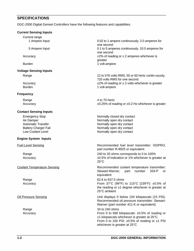
SPECIFICATIONS
DGC-2000 Digital Genset Controllers have the following features and capabilities.
Current Sensing Inputs
Current range1 Ampere Input 0.02 to 1 ampere continuously, 2.0 amperes for
one second5 Ampere Input 0.1 to 5 amperes continuously, 10.0 amperes for
one secondAccuracy ±2% of reading or ± 2 amperes whichever is
greaterBurden 1 volt-ampere
Voltage Sensing Inputs
Range 12 to 576 volts RMS, 50 or 60 hertz contin-uously,720 volts RMS for one second
Accuracy ±2% of reading or ± 2 volts whichever is greaterBurden 1 volt-ampere
Frequency
Range 4 to 70 hertzAccuracy ±0.25% of reading or ±0.2 Hz whichever is greater
Contact Sensing Inputs
Emergency Stop Normally closed dry contactAir Damper Normally open dry contactAutomatic Transfer Normally open dry contactBattery Charger Fail Normally open dry contactLow Coolant Level Normally open dry contact
Engine System Inputs
Fuel Level Sensing Recommended fuel level transmitter: ISSPRO,part number R-8925 or equivalent
Range 240 to 33 ohms corresponds to 0 to 100%Accuracy ±0.5% of indication or 1% whichever is greater at
25°C
Coolant Temperature Sensing Recommended coolant temperature transmitter:Stewart-Warner, part number 334-P orequivalent
Range 62.6 to 637.5 ohmsAccuracy From 37°C (99°F) to 115°C (239°F): ±0.5% of
the reading or ±1 degree whichever is greater at25°C ambient
Oil Pressure Sensing Unit displays 0 below 104 kilopascals (15 PSI).Recommended oil pressure transmitter: Stewart-Warner (part number 411-K or equivalent)
Range 34 to 240 ohmsAccuracy From 0 to 690 kilopascals: ±0.5% of reading or
±1 kilopascals whichever is greater at 25°C.From 0 to 100 PSI: ±0.5% of reading or ±1 PSIwhichever is greater at 25°C

DGC-2000 GENERAL INFORMATION 1-3
Battery Voltage Sensing
Range 12 or 24 volts nominal, 8 to 32 volts dc, batterydip ride through to 3 volts for 0.75 seconds
Accuracy ±0.5% of reading or ±0.1 volt whichever isgreater at 25°C
Burden 16 watts maximum
Magnetic Pickup Sensing
Voltage Range 3 volts peak (during cranking) to 35 volts peakcontinuous into 10 kohms
Frequency Range 32 to 10,000 hertz
Engine Alternator Voltage Sensing
Voltage Range 2 volts peak to 50 volts peakFrequency Range 100 to 900 hertz nominal
Engine RPM Sensing
Range 750 to 3600 RPMAccuracy ±0.5% of reading or ±1 RPM whichever is
greater at 25°C
Output Contacts
Contact Ratings For Engine Cranking Control The MASTER START, AUXILIARY START,FUEL SOLENOID, and ENGINE RUN relays arerated for 10 amperes at 24 Vdc, make, break,and carry
Contact Ratings For Protection Features The PRE-START, ALARM, PRE-ALARM, LOWOIL PRESSURE, LOW COOLANT TEMP-ERATURE, HIGH COOLANT TEMPERATURE,OVERCRANK, OVERSPEED, and AIRDAMPER relays are rated for 2 amperes at 24Vdc, make, break, and carry
Calculated Data
Power Factor (PF)
Range +1.0 to -1.0, both leading and laggingAccuracy ±0.01 PF of indication at 25°C
Kilo Volt-Amperes
Range 0 to 9,999 kVAAccuracy ±0.5% of reading or ±0.1 kVA whichever is
greater at 25°C
Kilowatts
Range 0 to 9,999 kWAccuracy ±0.5% of reading or ±0.1 kW whichever is
greater at 25°C
Kilowatt Hours
Range 0 to 999,999,999 kWhAccuracy ±0.5% of reading or ±1 kWh whichever is greater
at 25°C
Engine Run Time
Range 0 to 99,999 hoursAccuracy ±0.5% of reading or ±1 hour whichever is greater
at 25°C

1-4 DGC-2000 GENERAL INFORMATION
Maintenance Interval
Range 0 to 5,000 hoursAccuracy ±0.5% of reading or ±1 hour whichever is greater
at 25°C
Hardware
Communication Port
InterfaceRear RS-232 9600 baud, 8N1 full duplex
ProtocolsRear RS-232 Modbus
Isolation 2000 Vac at 50/60 Hz for one minute betweenground and voltage sensing inputs. 500 Vac at50/60 Hz for one minute between any of thefollowing groups
• Voltage Sensing - 70mA• Battery, Contact Sensing, and Remote
Panel - 42 mA• Current Transformer - 8mA• Communications Port - RS-232 - 6 mA• Contact Outputs - 23 mA
Impulse Qualified to IEC 255-5
Surge Withstand Capability
Oscillatory Qualified to ANSI/IEEE C37.90.1-1989 StandardSurge Withstand Capability (SWC) Tests forProtective Relays and Relay Systems.
Fast Transient Qualified to ANSI/IEEE C37.90.1-1989 StandardSurge Withstand Capability (SWC) Tests forProtective Relays and Relay Systems.
Radio Frequency Interference (RFI) Type tested using a 5 watt, hand-held trans-ceiver operating at random frequencies centeredaround 144 and 440 megahertz with the antennalocated within 6 inches (15 centimeters) of thedevice in both vertical and horizontal planes
UL Recognized/CSA Certified UL Recognized per Standard 508, UL File No.E97033. CSA Certified per Standard CAN/CSA-C22.2 No. 14-M91, CSA File No. LR 23131
Environment
Operating Temperature Range -40°C to 70°C (-40°F to 158°F)Storage Temperature Range -40°C to 85°C (-40°F to 185°F)
Salt Fog Qualified to ASTM-117B-1989 with the deviceunpowered for the 100 hour test duration
Vibration The device withstands 2 g in each of threemutually perpendicular planes, swept over therange of 10 to 500 Hz for a total of six sweeps, 15minutes each sweep, without structural damage ordegradation of performance
Shock 15 g
Weight Maximum weight 5.75 pounds (2.61 kilograms)

DGC-2000 HUMAN-MACHINE INTERFACE 2-1
SECTION 2 • HUMAN-MACHINE INTERFACE(Controls And Indicators)
GENERAL
This section provides a description of the DGC-2000 Digital Genset Controller human machine interfaceand illustrates the menu tree.
FRONT PANEL DISPLAY
Figure 2-1 shows the front panel human-machine interface (HMI) for a DGC-2000. Descriptions in Table2-1 refer to callouts in Figure 2-1.
Lamp
TestSilence
Alarm
Toggle
Phase
AutoOffR u n
Toggle
DisplayPrevious
Enter
Select
Scroll
Lower
Scroll
Raise
Run
TimeVoltage
Battery
Temperature
Coolant
Pressure
Oil
Voltage
Generator
Amps
Generator
Phase
Generator
Frequency
Generator
ControllerGensetDigital
Bas
ler
DGC-2000
Supplying
LoadAlarmAuto
Not In
A BC D
E
F
G
H
IJKLMNOPQRS
D2557-0904-09-97
Figure 2-1. DGC-2000 Front Panel
Table 2-1. DGC-2000 HMI (Controls And Indicators)
A Two line by twenty character LCD provides the primary visual interface for metering,alarms, prealarms, and protective functions. In the normal mode, labels appearabove and below the display. In the alternate display mode, labels and the displayedvalue appear on the display.
B Red LED turns ON when the device is not in the AUTO mode.
C Audible alarm annunciates when the unit is not in AUTO and when alarms andprealarms occur.

2-2 DGC-2000 HUMAN-MACHINE INTERFACE
Table 2-1. DGC-2000 HMI (Continued)
D Red LED turns ON continuously for all alarm conditions and flashes for prealarmconditions.
E Green LED turns ON when the generator is supplying more than two percent of ratedcurrent.
F Pushbutton used to silence the audible alarm.
G Pushbutton used to exercise all segments of the LCD and to illuminate all LED’s.
H Pushbutton used to place the device in AUTO mode.
I Green LED turns ON when the device is in the AUTO mode.
J Pushbutton used to place the unit in the OFF mode.
K Red LED turns ON when the device is in the OFF mode.
L Pushbutton used to place the device in the RUN mode.
M Green LED turns ON when the device is in the RUN mode.
N Pushbutton used to scroll through the displays available in the normal display mode.
O Pushbutton used to scroll through the display modes.
P Pushbutton used to scroll through previous menu levels.
Q Pushbutton used to enter menu sublevels and select set points.
R Pushbutton used to scroll backward through the menus and to decrement set points.
S Pushbutton used to scroll forward through the menus and to increment set points.
DGC-2000 CONNECTIONS
Compression type terminal strips make wiring the DGC-2000 a simple task. These connections acceptone #10 or two #14 AWG wires. These operations are made even easier by user friendly labeling of theterminal strips. Once wired, these terminals can be removed as an assembly and facilitate DGC-2000replacement for out of circuit testing or maintenance. Figure 2-2 shows the DGC-2000 rear panel terminalconnections. Descriptions in Table 2-2 refer to callouts in Figure 2-2.
Table 2-2. DGC-2000 Connections
A Connection points for the speed sensing inputs.
B Connection points for voltage sensing inputs.
C Connection points for current sensing inputs.
D Connection points for relay output contacts.
E Connection point for chassis ground.
F RS-232 serial communication port.
G Connection points for remote displays in accordance with the National Fire ProtectionAgency specifications.
H Connection points for operating power.
I Connection points for contact sensing inputs.
J Connection points for sending unit inputs.

DGC-2000 HUMAN-MACHINE INTERFACE 2-3
Figure 2-2. DGC-2000 Digital Genset Controller Rear Panel
GROUNDCHASSIS
R E M O T EDISPLAY
PO
WE
R-+
4321B
(+)
A (
-)
VOLTAGE SENSING
BUS G E N E R A T O RSIGNALSSPEEDSENDING UNIT
INPUTSC O N T A C T I N P U T S
27 28 29 30 31 32
PIC
K-U
PM
AG
NE
TIC
+-
BA
TT
ER
Y
CURRENT SENSINGRELAY OUTPUTS
PH
AS
EC
CT
PH
AS
EB
CT
A C
T1
A
CO
M
5 A
1 A
CO
M
5 A
1 A
PH
AS
E
5 A
CO
M
PR
E-S
TA
RT
ST
AR
TM
AS
TE
R
RU
N
ST
AR
TA
UX
ILIA
RY
SO
LEN
OID
FU
EL
PR
ES
SU
RE
LO O
IL
OV
ER
SP
EE
D
OV
ER
CR
AN
K
PR
E-A
LAR
M
TE
MP
HI
CO
OLA
NT
AIR
DA
MP
ER
ALA
RM
TE
MP
LO C
OO
LAN
T
PH
AS
E A
NE
UT
RA
L
PH
AS
E B
PH
AS
E C
PH
AS
E A
PH
AS
E B
26252423222120191817161514131211109876
LEV
EL
CO
OLA
NT
LE
VE
L
TE
MP
PR
ES
SU
RE
FA
ILU
RE
CH
AR
GE
R
TR
AN
S S
WIT
CH
AU
TO
MA
TIC
- + EM
ER
GE
NC
YS
TO
P
AIR
DA
MP
ER
5
RS 232
33 34 35 36 37 38 39 40 41 42 43 44 45 46 47 48 49 50 51 52 53 54 70696867666564636261605958575655
C
F
D
A BG I J
D2557-1505-08-98
E
H
OIL
FU
EL
CO
OL
AN
T
- + - + - + ALT
NR
ST
AT
OR
I

DGC-2000 FUNCTIONAL DESCRIPTION 3-1
SECTION 3 • FUNCTIONAL DESCRIPTION
GENERAL
DGC-2000 Digital Genset Controllers use microprocessor based technology to provide integrated engine-generator set control, protection, and metering in a single package. Microprocessor based technologyallows for exact measurement, set point adjustment, and timing functions. Refer to the followingparagraphs for the DGC-2000 functional description.
Circuit functional description is divided into Inputs, Microprocessor, Outputs, and Software. Circuitfunctions illustrated in Figure 3-1 are described in the following paragraphs.
R E G U L A T E DP O W E RS U P P L Y
E M E R G E N C Y S T O P
B A T T E R Y V O L T A G ESENSING AND
CONDIT IONING
CURRENT SENSINGA N D
CONDIT IONING
C O O L A N TT E M P E R A T U R E
SENSING
FUEL LEVELSENSING
OIL PRESSURESENSING
MAGNETIC P ICKUPSENSING
A L T E R N A T O RSENSING
CONTACT SENSING
AC VOLTAGE SENSINGA N D
CONDIT IONING
A N A L O G
T O
DIGITAL
C O N V E R T E R
M A S T E R S T A R T
ZERO CROSSDETECTION
AUXILLARY START
R U N
FUEL SOLONOID
LOW OIL PRESSURE
OVER CRANK
HIGH COOLANT TEMP
OVER SPEED
PRE-START
PRE-ALARM
AIR DAMPER CLOSE
A L A R M
L O W C O O L A N T T E M P
OPTO ISOLATION
LIQUIDC R Y S T A LDISPLAY
RS-232
M I C R OC O N T R O L L E R
BATTERY
S T O P
A CV O L T A G E
A CC U R R E N T
C O O L A N TSENSING
FUELSENSING
OILSENSING
M A GPICKUP
ALTS T A T O R
S W I T C HINPUTS
D2557-1604-21-97
Figure 3-1. DGC-2000 Functional Block Diagram
3-2 DGC-2000 FUNCTIONAL DESCRIPTION
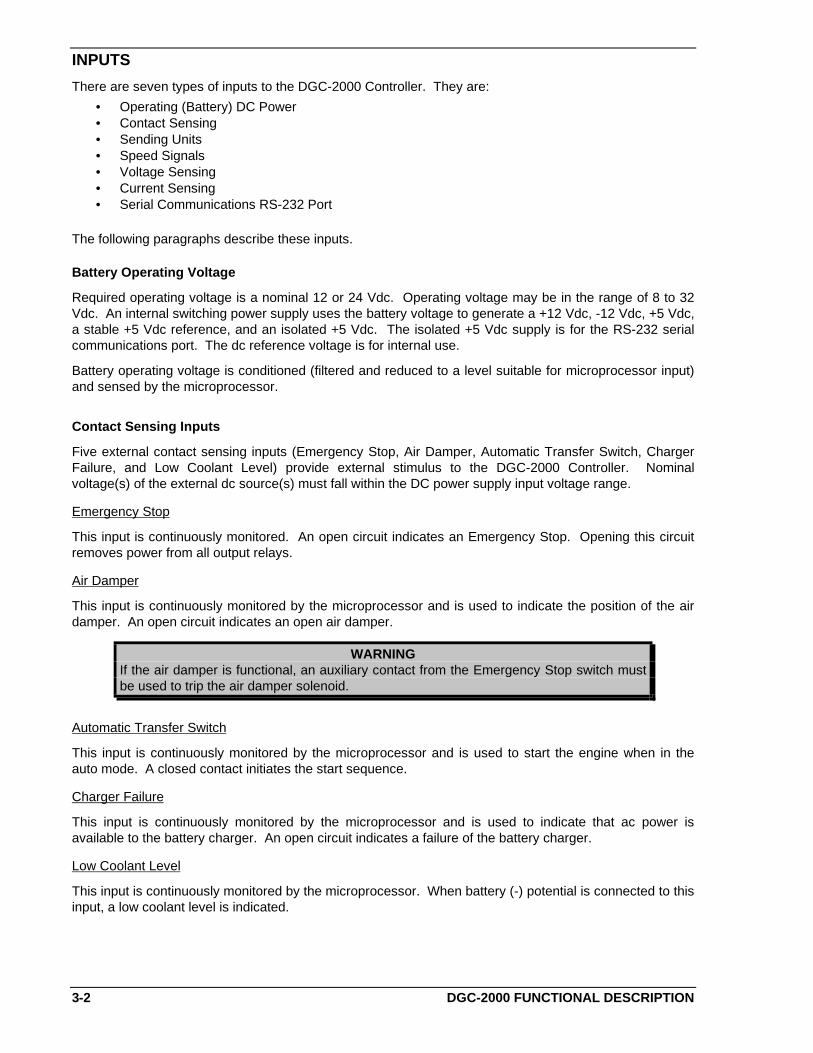
INPUTS
There are seven types of inputs to the DGC-2000 Controller. They are:
• Operating (Battery) DC Power• Contact Sensing• Sending Units• Speed Signals• Voltage Sensing• Current Sensing• Serial Communications RS-232 Port
The following paragraphs describe these inputs.
Battery Operating Voltage
Required operating voltage is a nominal 12 or 24 Vdc. Operating voltage may be in the range of 8 to 32Vdc. An internal switching power supply uses the battery voltage to generate a +12 Vdc, -12 Vdc, +5 Vdc,a stable +5 Vdc reference, and an isolated +5 Vdc. The isolated +5 Vdc supply is for the RS-232 serialcommunications port. The dc reference voltage is for internal use.
Battery operating voltage is conditioned (filtered and reduced to a level suitable for microprocessor input)and sensed by the microprocessor.
Contact Sensing Inputs
Five external contact sensing inputs (Emergency Stop, Air Damper, Automatic Transfer Switch, ChargerFailure, and Low Coolant Level) provide external stimulus to the DGC-2000 Controller. Nominalvoltage(s) of the external dc source(s) must fall within the DC power supply input voltage range.
Emergency Stop
This input is continuously monitored. An open circuit indicates an Emergency Stop. Opening this circuitremoves power from all output relays.
Air Damper
This input is continuously monitored by the microprocessor and is used to indicate the position of the airdamper. An open circuit indicates an open air damper.
WARNINGIf the air damper is functional, an auxiliary contact from the Emergency Stop switch mustbe used to trip the air damper solenoid.
Automatic Transfer Switch
This input is continuously monitored by the microprocessor and is used to start the engine when in theauto mode. A closed contact initiates the start sequence.
Charger Failure
This input is continuously monitored by the microprocessor and is used to indicate that ac power isavailable to the battery charger. An open circuit indicates a failure of the battery charger.
Low Coolant Level
This input is continuously monitored by the microprocessor. When battery (-) potential is connected to thisinput, a low coolant level is indicated.

DGC-2000 FUNCTIONAL DESCRIPTION 3-3
Sending Unit Inputs
Coolant temperature
A current of less than two milliamperes is provided to the coolant temperature sending unit. Thedeveloped voltage is measured and scaled for use by the internal circuitry.
Oil Pressure
A current of less than 15 milliamperes is provided to the oil pressure sending unit. The developed voltageis measured and scaled for use by the internal circuitry.
Fuel level
A current of less than 15 milliamperes is provided to the fuel level sending unit. The developed voltage ismeasured and scaled for use by the internal circuitry.
Speed Signal Inputs
Magnetic Pickup
The voltage from the magnetic pickup is scaled and conditioned for use by the internal circuitry as a speedsignal source.
Alternator Sensing
The voltage from the engine alternator stator is scaled and conditioned for use by the internal circuitry as aspeed signal source.
Voltage Inputs
Monitored generator and bus voltages are sensed and scaled to levels suitable for use by the internalcircuitry. Differential amplifiers provide isolation for these inputs. Internal solid state switches selectline-to-line, line-to-neutral or single-phase values. Menu selections by the user determine these switchsettings.
Current Inputs
Monitored generator currents are sensed and scaled to values suitable for use by the internal circuitry.Internal current transformers provide isolation. Two taps on the primary of these transformersaccommodate either one or five ampere circuits.
Serial Communications Input
This serial communications link connects via optically isolated circuitry to the microprocessor. Enhancedaccess to device functions and real time, remote metering capabilities are available through this port. TheDGC 2000 emulates a subset of the Modicon 984 programmable controller. Basler Electric customsoftware provides easy access to these functions.
MICROPROCESSOR
Software programmed in the erasable programmable read-only memory (EPROM) controls the overallfunctionality of the device and makes all decisions based on programming and system inputs. Formulasthat are used to determine the various calculated quantities and circuits related to microprocessor inputsare described in the follow paragraphs.
Formulas
Formulas used in calculating the various quantities are provided in the following paragraphs.

3-4 DGC-2000 FUNCTIONAL DESCRIPTION
For line-to-neutral (VL-N) voltage sensing: V = V + V V + Vab a2
a b b2
V = V + V V + Vbc b2
b c c2
V = V + V V + Vca c2
c a a2
For all three-phase voltage sensing configurations:
kVA: kVA A Phase = (Vab × Ia) divided by (1000 times square-root of three)kVA B Phase = (Vbc × Ib) divided by (1000 times square-root of three)kVA C Phase = (Vca × Ic) divided by (1000 times square-root of three)
Total kVA = kVA A Phase + kVA B Phase + kVA C Phase
kW: kW A Phase = kVA A Phase times Power FactorkW B Phase = kVA B Phase times Power FactorkW C Phase = kVA C Phase times Power Factor
Total kW = Total kVA × PF
Power Factor (PF) = Cosine of the measured angle between voltage and current zero crossings
Related Circuits
Zero Crossing Detection
The zero crossing of the A phase voltage and the B phase current is detected and used to calculate thephase angle between the current and voltage. This zero crossing is also used to measure the bus andgenerator frequencies.
Signal Switching
Solid state switches, under microprocessor control, select the voltage or current sensing signal that isapplied to the RMS to dc converter. The resulting signal is sent to the twelve bit analog-to-digitalconverter where it is digitized for use by the microprocessor.
RMS To DC Converter
Scaled and conditioned signals representing the voltage and current sensing inputs are used as the inputto the RMS to dc converter. This converter output is a dc level proportional to the RMS value of the input.
Analog To Digital Converter
Signals from the RMS to dc converter, coolant temperature sensing input, fuel level sensing input, and theoil pressure sensing input are digitized by the twelve-bit analog to digital converter. The digitizedinformation is stored in random access memory (RAM). This information is used by the microprocessorfor all metering and protection functions.
OUTPUTS
Each output relay is controlled by the microprocessor and the emergency stop contact input. When theemergency stop contact input is open, all output contacts open. When the emergency stop contact inputis closed and a signal is given by the microprocessor, the output contacts close. All outputs areelectrically isolated from each other and from the internal circuitry. Four outputs (master start, auxiliarystart, run, and fuel solenoid) are associated with engine cranking functions. The remaining nine outputs(Figure 3-1) are associated with the various alarms, prealarms, and prestart.
WARNINGIf the air damper is functional, an auxiliary contact from the Emergency Stop switch mustbe used to trip the air damper solenoid.
DGC-2000 FUNCTIONAL DESCRIPTION 3-5
SOFTWARE
Software embedded in the DGC-2000 controls all aspects of device functionality. This comprises powerup initialization, front panel set up and configuration, input contact status monitoring, protective functiondetection and annunciation, system parameter monitoring, output contact status control, and RS-232serial communications.
When battery power is first applied, the DGC 2000 initiates a power up sequence. The version ofembedded software is displayed on the LCD and the memory is checked. Then all configuration datastored in non-volatile EEPROM is brought into main memory. Immediately after this, the LCD displaybegins the Normal mode. When the Normal mode is displayed, all enabled functions are activated andinput monitoring begins.
NOTE
The run time counter, kilowatt-hour meter and maintenance timers are updated in volatilememory every minute. The updated value is saved to non-volatile memory only whenauto/off/run mode of operation is changed. This can be changed either from the frontpanel or through the communications port. Should the battery power source fail duringoperation these values will not be updated and the change in value incurred since the lastchange of mode will not be saved. This information is irretrievably lost.
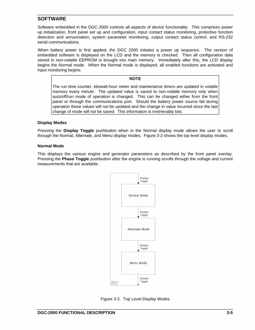
Display Modes
Pressing the Display Toggle pushbutton when in the Normal display mode allows the user to scrollthrough the Normal, Alternate, and Menu display modes. Figure 3-2 shows the top level display modes.
Normal Mode
This displays the various engine and generator parameters as described by the front panel overlay.Pressing the Phase Toggle pushbutton after the engine is running scrolls through the voltage and currentmeasurements that are available.
Normal Mode
Alternate Mode
Menu Mode
DisplayToggle
DisplayToggle
DisplayToggle
DisplayToggleD2557-18
04-22-97
Figure 3-2. Top Level Display Modes
3-6 DGC-2000 FUNCTIONAL DESCRIPTION
Menu Mode
After pressing the Display Toggle pushbutton twice to begin the Menu display mode (first time selects theAlternate mode), pressing Select/Enter begins the next level of menus. Pressing the Raise/Scroll orLower/Scroll pushbutton (Figure 3-3) allows the user to scroll through the menu display mode screens.Pressing the Display Toggle pushbutton returns the display to the Normal mode.
Menu 1. Menu 1 is the alarm and prealarm menu. Pressing Select/Enter (Figure 3-4) from this menubegins the 1.x menu level. Pressing Raise/Scroll and Lower/Scroll from this menu scrolls through the1.x menu level.
Menu 1.1. Menu 1.1 displays the overspeed alarm. Pressing Select/Enter begins the 1.1.1 level ofmenus and displays the function activation level. Pressing Select/Enter displays the setting. This is notadjustable from the front panel. Pressing previous goes back to the 1.1.1 level.
Pressing Raise/Scroll or Lower/Scroll begins the 1.1.2 function activation delay level of menus.Pressing Select/Enter displays the activation delay time once the level has been exceeded. This is notadjustable from the front panel.
Pressing Previous twice goes back to the 1.1 level. Pressing Raise/Scroll goes to the 1.2 menu levelPressing Lower/Scroll goes to the 1.13 menu level.
Menu 1.2. Menu 1.2 displays high coolant temperature alarm. Pressing Select/Enter begins the 1.2.1level of menus and displays the function activation level. Pressing Select/Enter displays the setting. Thisis not adjustable from the front panel.
Pressing Previous goes back to the 1.2.1 level. Pressing Raise/Scroll or Lower/Scroll begins the 1.2.2function activation delay level of menus. Pressing Select/Enter displays the activation delay time oncethe engine crank disconnect speed is exceeded. This is not adjustable from the front panel.
Pressing Previous twice goes back to the 1.2 level. Pressing Raise/Scroll goes to the 1.3 menu levelPressing Lower/Scroll goes to the 1.1 menu level.

DGC-2000 FUNCTIONAL DESCRIPTION 3-7
Menu 1Main Alarms
and Pre-Alarms
Menu 2System
Configurat ion
Menu 3Sensing Devices
Menu 4Engine Parameters
and Cranking
EnterMenuMode
D/T
Lower
Raise
Menu ModeIntro Screen
Enter
Raise
Raise
Raise
Lower
Lower
Lower
D2609-0104-23-97
Figure 3-3. Menu Display Modes

3-8 DGC-2000 FUNCTIONAL DESCRIPTION
Menu 1Main Alarms
and Pre-Alarms
Menu 1.1Overspeed
Alarm
Menu 1.2High Coolant
Temperature Alarm
Menu 1.3High CoolantTemperature
Pre-Alarm
Menu 1.13Engine
MaintenanceCycle Pre-Alarm
Menu 1.12Engine ki loWatt
Over load Pre-Alarm
Menu 1.11Battery Charger
Fai lure Pre-Alarm
Menu 1.4Low CoolantTemperature
Pre-Alarm
Menu 1.10Battery Over-
Voltage Pre-Alarm
Menu 1.9Low BatteryPre-Alarm
Menu 1.5Low Oil Pressure
Alarm
Menu 1.6Low Oil Pressure
Pre-Alarm
Menu 1.8Weak Bat tery
Pre-Alarm
Enter
Prev
Prev
Lower
Raise
Menu 1.7Low Fuel
Pre-Alarm
Raise
Raise
Raise
Raise
RaiseRaise
Raise
Raise
Raise
Raise
Lower
Lower
Lower
Lower
Lower
LowerLower
Lower
Lower
Lower
Lower
Raise
Raise
Lower
D2609-0205-07-98
Figure 3-4. Menu 1
Menu 1.3. Menu 1.3 displays high coolant temperature prealarm. Pressing Select/Enter begins the 1.3.1level of menus and displays the function activation level. Pressing Select/Enter displays the setting. Thisis not adjustable from the front panel.
Pressing Previous goes back to the 1.3.1 level. Pressing Raise/Scroll or Lower/Scroll begins the 1.3.2function activation delay level of menus. Pressing Select/Enter displays the activation delay time oncethe engine crank disconnect speed is exceeded. This is not adjustable from the front panel.
DGC-2000 FUNCTIONAL DESCRIPTION 3-9
Pressing Previous twice goes back to the 1.3 level. Pressing Raise/Scroll goes to the 1.4 menu levelPressing Lower/Scroll goes to the 1.2 menu level.
Menu 1.4. Menu 1.4 displays low coolant temperature prealarm. Pressing Select/Enter begins the 1.4.1level of menus and displays the function activation level. Pressing Select/Enter displays the setting. Thisis not adjustable from the front panel.
Pressing Previous goes back to the 1.4.1 level. Pressing Raise/Scroll or Lower/Scroll begins the 1.4.2function activation delay level of menus. Pressing Select/Enter displays the activation delay time oncethe level has been exceeded. This is not adjustable from the front panel.
Pressing Previous twice goes back to the 1.4 level. Pressing Raise/Scroll goes to the 1.5 menu levelPressing Lower/Scroll goes to the 1.3 menu level.
Menu 1.5. Menu 1.5 displays low oil pressure alarm. Pressing Select/Enter begins the 1.5.1 level ofmenus and displays the function activation level. Pressing Select/Enter displays the setting. This is notadjustable from the front panel.
Pressing Previous goes back to the 1.5.1 level. Pressing Raise/Scroll or Lower/Scroll begins the 1.5.2function activation delay level of menus. Pressing Select/Enter displays the activation delay time oncethe engine crank disconnect speed is exceeded. This is not adjustable from the front panel.
Pressing Previous twice goes back to the 1.5 level. Pressing Raise/Scroll goes to the 1.6 menu levelPressing Lower/Scroll goes to the 1.4 menu level.
Menu 1.6. Menu 1.6 displays low oil pressure prealarm. Pressing Select/Enter begins the 1.6.1 level ofmenus and displays the function activation level. Pressing Select/Enter displays the setting. This is notadjustable from the front panel.
Pressing Previous goes back to the 1.6.1 level. Pressing Raise/Scroll or Lower/Scroll begins the 1.6.2function activation delay level of menus. Pressing Select/Enter displays the activation delay time oncethe engine crank disconnect speed is exceeded. This is not adjustable from the front panel.
Pressing Previous twice goes back to the 1.6 level. Pressing Raise/Scroll goes to the 1.7 menu levelPressing Lower/Scroll goes to the 1.5 menu level.
Menu 1.7. Menu 1.7 displays low fuel level prealarm. Pressing Select/Enter begins the 1.7.1 level ofmenus and displays the function activation level. Pressing Select/Enter displays the setting. This isadjustable from the front panel.
Pressing Previous goes back to the 1.7.1 level. Pressing Raise/Scroll or Lower/Scroll begins the 1.7.2function activation delay level of menus. Pressing Select/Enter displays the activation delay time oncethe level has been exceeded. After pressing Raise/Scroll or Lower/Scroll, the user will be instructed toenter the user key code. After entering the user key code followed by pressing Select/Enter twice, thesetting will be adjustable with the Raise/Scroll and Lower/Scroll keys. After the desired setting has beenselected, press Select/Enter to save the new settings.
Pressing Previous twice goes back to the 1.7 level. Pressing Raise/Scroll goes to the 1.8 menu levelPressing Lower/Scroll goes to the 1.6 menu level.
Menu 1.8. Menu 1.8 displays weak battery prealarm. Pressing Select/Enter begins the 1.8.1 level ofmenus and displays the function activation level. Pressing Select/Enter displays the setting. This is notadjustable from the front panel.
Pressing Previous goes back to the 1.8.1 level. Pressing Raise/Scroll or Lower/Scroll begins the 1.8.2function activation delay level of menus. Pressing Select/Enter displays the activation delay time oncethe level has been exceeded. This is not adjustable from the front panel.
Pressing Previous twice goes back to the 1.8 level. Pressing Raise/Scroll goes to the 1.9 menu levelPressing Lower/Scroll goes to the 1.7 menu level.
Menu 1.9. Menu 1.9 displays low battery prealarm. Pressing Select/Enter begins the 1.9.1 level ofmenus and displays the function activation level. Pressing Select/Enter displays the setting. This is notadjustable from the front panel.

3-10 DGC-2000 FUNCTIONAL DESCRIPTION
Pressing Previous goes back to the 1.9.1 level. Pressing Raise/Scroll or Lower/Scroll begins the 1.9.2function activation delay level of menus. Pressing Select/Enter displays the activation delay time oncethe level has been exceeded. This is not adjustable from the front panel.
Pressing Previous twice goes back to the 1.9 level. Pressing Raise/Scroll goes to the 1.10 menu levelPressing Lower/Scroll goes to the 1.8 menu level.
Menu 1.10. Menu 1.10 displays battery over voltage prealarm. Pressing Select/Enter begins the 1.10.1level of menus and displays the function activation level. Pressing Select/Enter displays the setting. Thisis not adjustable from the front panel.
Pressing Previous goes back to the 1.10.1 level. Pressing Raise/Scroll or Lower/Scroll begins the1.10.2 function activation delay level of menus. Pressing Select/Enter displays the activation delay timeonce the level has been exceeded. This is not adjustable from the front panel.
Pressing Previous twice goes back to the 1.10 level. Pressing Raise/Scroll goes to the 1.11 menu levelPressing Lower/Scroll goes to the 1.9 menu level.
Menu 1.11. Menu 1.11 displays battery charger failure prealarm. Pressing Select/Enter begins the1.11.1 level of menus and displays the function activation level. Pressing Select/Enter displays thesetting. This is not adjustable from the front panel.
Pressing Previous goes back to the 1.11.1 level. Pressing Raise/Scroll or Lower/Scroll begins the1.11.2 function activation delay level of menus. Pressing Select/Enter displays the activation delay timeonce the level has been exceeded. This is not adjustable from the front panel.
Pressing Previous twice goes back to the 1.11 level. Pressing Raise/Scroll goes to the 1.12 menu levelPressing Lower/Scroll goes to the 1.10 menu level.
Menu 1.12. Menu 1.12 displays kilowatt overload prealarm. Pressing Select/Enter begins the 1.12.1level of menus and displays the function activation level. Pressing Select/Enter displays the setting. Thisis not adjustable from the front panel.
Pressing Previous goes back to the 1.12.1 level. Pressing Raise/Scroll or Lower/Scroll begins the1.12.2 function activation delay level of menus. Pressing Select/Enter displays the activation delay timeonce the level has been exceeded. This is not adjustable from the front panel.
Pressing Previous twice goes back to the 1.12 level. Pressing Raise/Scroll goes to the 1.13 menu levelPressing Lower/Scroll goes to the 1.11 menu level.
Menu 1.13. Menu 1.13 display engine maintenance prealarm. Pressing Select/Enter begins the 1.13.1level of menus and displays the function activation level. Pressing Select/Enter displays the setting. Thisis not adjustable from the front panel.
Pressing Previous goes back to the 1.13.1 level. Pressing Raise/Scroll or Lower/Scroll begins the1.13.2 function activation delay level of menus. Pressing Select/Enter displays the activation delay timeonce the level has been exceeded. This is not adjustable from the front panel.
Pressing Previous twice goes back to the 1.13 level. Pressing Raise/Scroll goes to the 1.1 menu level.Pressing Lower/Scroll goes to the 1.12 menu level.
Pressing Previous from any 1.x level menu goes to menu 1. Pressing Raise/Scroll goes to menu 2.Pressing Lower/Scroll goes to menu 4.
DGC-2000 FUNCTIONAL DESCRIPTION 3-11
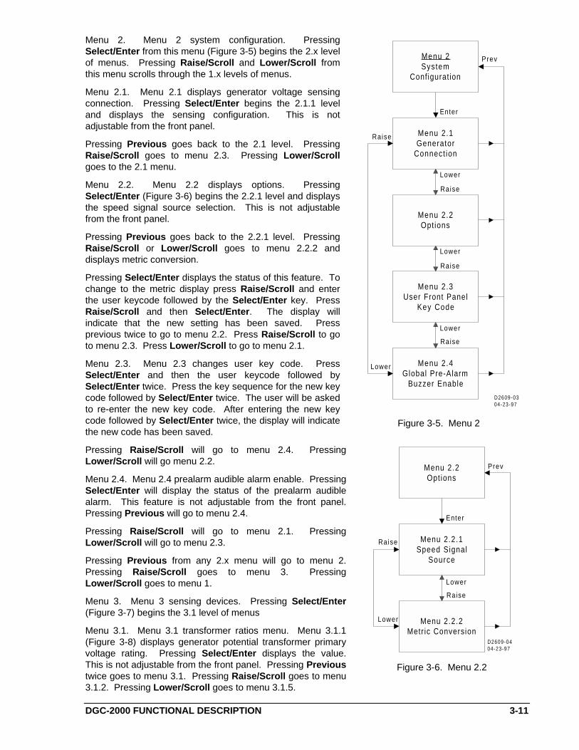
Menu 2. Menu 2 system configuration. PressingSelect/Enter from this menu (Figure 3-5) begins the 2.x levelof menus. Pressing Raise/Scroll and Lower/Scroll fromthis menu scrolls through the 1.x levels of menus.
Menu 2.1. Menu 2.1 displays generator voltage sensingconnection. Pressing Select/Enter begins the 2.1.1 leveland displays the sensing configuration. This is notadjustable from the front panel.
Pressing Previous goes back to the 2.1 level. PressingRaise/Scroll goes to menu 2.3. Pressing Lower/Scrollgoes to the 2.1 menu.
Menu 2.2. Menu 2.2 displays options. PressingSelect/Enter (Figure 3-6) begins the 2.2.1 level and displaysthe speed signal source selection. This is not adjustablefrom the front panel.
Pressing Previous goes back to the 2.2.1 level. PressingRaise/Scroll or Lower/Scroll goes to menu 2.2.2 anddisplays metric conversion.
Pressing Select/Enter displays the status of this feature. Tochange to the metric display press Raise/Scroll and enterthe user keycode followed by the Select/Enter key. PressRaise/Scroll and then Select/Enter. The display willindicate that the new setting has been saved. Pressprevious twice to go to menu 2.2. Press Raise/Scroll to goto menu 2.3. Press Lower/Scroll to go to menu 2.1.
Menu 2.3. Menu 2.3 changes user key code. PressSelect/Enter and then the user keycode followed bySelect/Enter twice. Press the key sequence for the new keycode followed by Select/Enter twice. The user will be askedto re-enter the new key code. After entering the new keycode followed by Select/Enter twice, the display will indicatethe new code has been saved.
Pressing Raise/Scroll will go to menu 2.4. PressingLower/Scroll will go menu 2.2.
Menu 2.4. Menu 2.4 prealarm audible alarm enable. PressingSelect/Enter will display the status of the prealarm audiblealarm. This feature is not adjustable from the front panel.Pressing Previous will go to menu 2.4.
Pressing Raise/Scroll will go to menu 2.1. PressingLower/Scroll will go to menu 2.3.
Pressing Previous from any 2.x menu will go to menu 2.Pressing Raise/Scroll goes to menu 3. PressingLower/Scroll goes to menu 1.
Menu 3. Menu 3 sensing devices. Pressing Select/Enter(Figure 3-7) begins the 3.1 level of menus
Menu 3.1. Menu 3.1 transformer ratios menu. Menu 3.1.1(Figure 3-8) displays generator potential transformer primaryvoltage rating. Pressing Select/Enter displays the value.This is not adjustable from the front panel. Pressing Previoustwice goes to menu 3.1. Pressing Raise/Scroll goes to menu3.1.2. Pressing Lower/Scroll goes to menu 3.1.5.
Menu 2.3User Front Panel
Key Code
Menu 2.4Global Pre-Alarm
Buzzer Enable
Menu 2.1Generator
Connect ion
Menu 2.2Opt ions
Menu 2System
Configurat ion
Prev
Enter
Lower
Raise
Raise
Raise
Raise
Lower
Lower
Lower
D2609-0304-23-97
Figure 3-5. Menu 2
Menu 2.2.1Speed Signal
Source
Menu 2.2.2Metr ic Conversion
Menu 2.2Opt ions
Prev
Enter
Lower
Raise
Raise
Lower
D2609-0404-23-97
Figure 3-6. Menu 2.2

3-12 DGC-2000 FUNCTIONAL DESCRIPTION
Menu 3.1.1Generator PT'sPrimary Rat ing
Menu 3.1.2Generator PT's
Secondary Rat ing
Menu 3.1.3Generator CT'sPr imary Rat ing
Menu 3.1.5Bus PT's
Secondary Rat ing
Menu 3.1.4Bus PT's
Pr imary Rat ing
Menu 3.1Transformer Rat ios
Enter
Prev
Raise
Lower
Lower
Lower
Lower
Lower
Raise
Raise
Raise
Raise
D2609-0604-23-97
Figure 3-8. Menu 3.1
Menu 3.1.2. Menu 3.1.2 displays the generator potential transformer secondary voltage rating. PressingSelect/Enter displays the value. This is not adjustable from the front panel. Pressing previous goes tomenu 3.1. Pressing Raise/Scroll goes to menu 3.1.3 Pressing Lower/Scroll goes to menu 3.1.1.
Menu 3.1.3. Menu 3.1.3 displays the generator current transformer primary current rating. PressingSelect/Enter displays the value. This is not adjustable from the front panel. Pressing previous goes tomenu 3.1. Pressing Raise/Scroll goes to menu 3.1.4. Pressing Lower/Scroll goes to menu 3.1.2.
Menu 3.1.4. Menu 3.1.4 displays the bus potential transformer primary voltage rating. PressingSelect/Enter displays the value. This is not adjustable from the front panel. Pressing previous goes tomenu 3.1. Pressing Raise/Scroll goes to menu 3.1.5. Pressing Lower/Scroll goes to menu 3.1.3.
Menu 3.1.5. Menu 3.1.5 displays the bus potential transformer secondary voltage rating. PressingSelect/Enter displays the value. This is not adjustable from the front panel. Pressing previous goes tomenu 3.1. Pressing Raise/Scroll goes to menu 3.1.1. Pressing Lower/Scroll goes to menu 3.1.4.
Pressing Raise/Scroll from menu 3.1 goes to menu 3.2.
Menu 3Sensing Devices
Menu 3.1Transformer Rat ios
Enter
Prev
Lower
Menu 3.2Sender Fai lure
Alarms
Raise
Menu 3.3Input Calibration
Funct ion
Lower
Raise
Raise
Lower
D2609-0505-15-97
Figure 3-7. Menu 3
DGC-2000 FUNCTIONAL DESCRIPTION 3-13
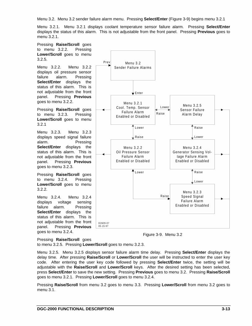
Menu 3.2. Menu 3.2 sender failure alarm menu. Pressing Select/Enter (Figure 3-9) begins menu 3.2.1
Menu 3.2.1. Menu 3.2.1 displays coolant temperature sensor failure alarm. Pressing Select/Enterdisplays the status of this alarm. This is not adjustable from the front panel. Pressing Previous goes tomenu 3.2.1.
Pressing Raise/Scroll goesto menu 3.2.2. PressingLower/Scroll goes to menu3.2.5.
Menu 3.2.2. Menu 3.2.2displays oil pressure sensorfailure alarm. PressingSelect/Enter displays thestatus of this alarm. This isnot adjustable from the frontpanel. Pressing Previousgoes to menu 3.2.2.
Pressing Raise/Scroll goesto menu 3.2.3. PressingLower/Scroll goes to menu3.2.1
Menu 3.2.3. Menu 3.2.3displays speed signal failurealarm. PressingSelect/Enter displays thestatus of this alarm. This isnot adjustable from the frontpanel. Pressing Previousgoes to menu 3.2.3.
Pressing Raise/Scroll goesto menu 3.2.4. PressingLower/Scroll goes to menu3.2.2.
Menu 3.2.4. Menu 3.2.4displays voltage sensingfailure alarm. PressingSelect/Enter displays thestatus of this alarm. This isnot adjustable from the frontpanel. Pressing Previousgoes to menu 3.2.4.
Pressing Raise/Scroll goesto menu 3.2.5. Pressing Lower/Scroll goes to menu 3.2.3.
Menu 3.2.5. Menu 3.2.5 displays sensor failure alarm time delay. Pressing Select/Enter displays thedelay time. After pressing Raise/Scroll or Lower/Scroll the user will be instructed to enter the user keycode. After entering the user key code followed by pressing Select/Enter twice, the setting will beadjustable with the Raise/Scroll and Lower/Scroll keys. After the desired setting has been selected,press Select/Enter to save the new setting. Pressing Previous goes to menu 3.2. Pressing Raise/Scrollgoes to menu 3.2.1. Pressing Lower/Scroll goes to menu 3.2.4.
Pressing Raise/Scroll from menu 3.2 goes to menu 3.3. Pressing Lower/Scroll from menu 3.2 goes tomenu 3.1.
Menu 3.2Sender Fai lure Alarms
Menu 3.2.1Cool. Temp. Sensor
Fai lure AlarmEnabled or Disabled
Menu 3.2.5Sensor Fai lure
Alarm Delay
Menu 3.2.3Speed SignalFai lure Alarm
Enabled or Disabled
Menu 3.2.2Oil Pressure Sensor
Fai lure AlarmEnabled or Disabled
Enter
Prev
Raise
Lower
Menu 3.2.4Generator Sensing Vol-
tage Fai lure AlarmEnabled or Disabled
Lower
Lower
Lower
Lower
Raise
Raise
Raise
Raise
D2609-0705-15-97
Figure 3-9. Menu 3.2

3-14 DGC-2000 FUNCTIONAL DESCRIPTION
Menu 3.3. Menu 3.3 displays the input calibration function. This function is for Basler Electric Companyuse only. For more information contact Basler Electric Company.
Pressing Previous goes to menu 3. Pressing Raise/Scroll from menu 3 goes to menu 4. PressingLower/Scroll goes to menu 2.
Menu 4. Menu 4 (Figure 3-10)displays engine parameters andcranking. Pressing Select/Enterfrom menu 4 begins menu 4.1.
Menu 4.1. Menu 4.1 displayscool down time. After pressingRaise/Scroll or Lower/Scroll,the user will be instructed toenter the user key code. Afterentering the user key codefollowed by pressingSelect/Enter twice, the settingwill be adjustable with theRaise/Scroll and Lower/Scrollkeys. After the desired settinghas been selected, pressSelect/Enter to save the newsetting. Pressing Previous goesto menu 4.1. PressingRaise/Scroll goes to menu 4.2.Pressing Lower/Scroll goes tomenu 4.7.
Menu 4.2. Menu 4.2 displayscranking mode. PressingSelect/Enter displays thecranking mode selected. This isnot adjustable from the frontpanel. Pressing Previous goesto menu 4.2. PressingRaise/Scroll goes to menu 4.3.Pressing Lower/Scroll goes tomenu 4.1.
Menu 4.3. Menu 4.3 displays thenumber of crank cycles. Pressing Select/Enter displays the number of crank cycles selected. This is notadjustable from the front panel. Pressing Previous goes to menu 4.3. Pressing Raise/Scroll goes tomenu 4.4. Pressing Lower/Scroll goes to menu 4.2.
Menu 4.4. Menu 4.4 displays continuous crank time. Pressing Select/Enter displays the continuouscrank time selected. This is not adjustable from the front panel. Pressing Previous goes to menu 4.4.Pressing Raise/Scroll goes to menu 4.5. Pressing Lower/Scroll goes to menu 4.3.
Menu 4.5. Menu 4.5 displays cycle crank time. Pressing Select/Enter displays the cycle crank timeselected. This is not adjustable from the front panel. Pressing Previous goes to menu 4.5. PressingRaise/Scroll goes to menu 4.6. Pressing Lower/Scroll goes to menu 4.4.
Menu 4.6. Menu 4.6 displays precrank delay time. After pressing Raise/Scroll or Lower/Scroll, the userwill be instructed to enter the user key code. After entering the user key code followed by pressingSelect/Enter twice, the setting will be adjustable with the Raise/Scroll and Lower/Scroll keys. After thedesired setting has been selected press Select/Enter to save the new setting. Pressing Previous goes tomenu 4.6. Pressing Raise/Scroll goes to menu 4.7. Pressing Lower/Scroll goes to menu 4.5.
Menu 4Engine Parameters
and Cranking
Menu 4.7Pre-Crank Contact
After Cranking
Menu 4.1Cool Down Time
Menu 4.6Pre-Crank Delay
Menu 4.5Cycle Crank Time
Menu 4.3No. of Crank Cycles
Menu 4.4Cont inuousCrank Time
Prev
Lower
Raise
Enter
Raise
Raise
Raise
Raise
RaiseLower
Lower
Lower
Lower
Lower
Menu 4.2Cranking Mode
LowerRaise
D260-0804-23-97
Figure 3-10. Menu 4
DGC-2000 FUNCTIONAL DESCRIPTION 3-15
Menu 4.7. Menu 4.7 displays the status of the Precrank contact after cranking. After pressingRaise/Scroll or Lower/Scroll, the user will be instructed to enter the user key code. After entering theuser key code followed by pressing Select/Enter twice, the setting will be adjustable with the Raise/Scrolland Lower/Scroll keys. After the desired setting has been selected, press Select/Enter to save the newsetting. Pressing Previous goes to menu 4.7. Pressing Raise/Scroll goes to menu 4.1. PressingLower/Scroll goes to menu 4.6.
Pressing Previous twice goes to the normal display mode.
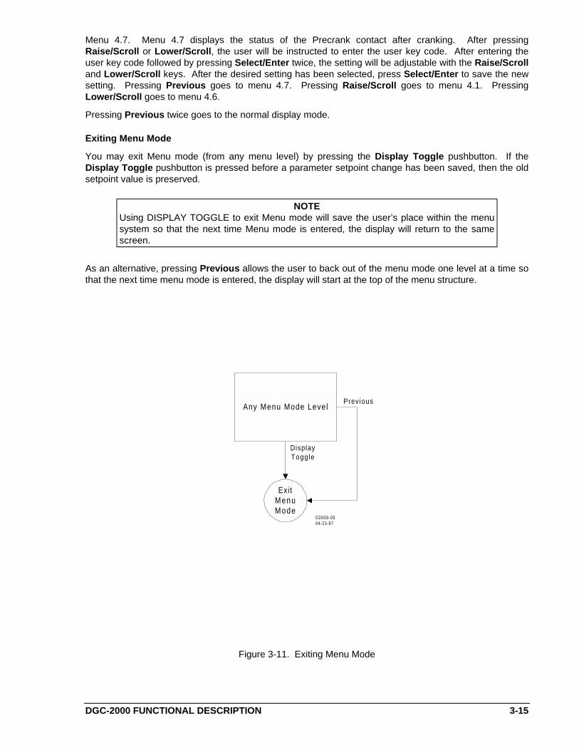
Exiting Menu Mode
You may exit Menu mode (from any menu level) by pressing the Display Toggle pushbutton. If theDisplay Toggle pushbutton is pressed before a parameter setpoint change has been saved, then the oldsetpoint value is preserved.
NOTEUsing DISPLAY TOGGLE to exit Menu mode will save the user’s place within the menusystem so that the next time Menu mode is entered, the display will return to the samescreen.
As an alternative, pressing Previous allows the user to back out of the menu mode one level at a time sothat the next time menu mode is entered, the display will start at the top of the menu structure.
ExitMenuMode
Any Menu Mode Level
DisplayToggle
D2609-0904-23-97
Prev ious
Figure 3-11. Exiting Menu Mode
3-16 DGC-2000 FUNCTIONAL DESCRIPTION
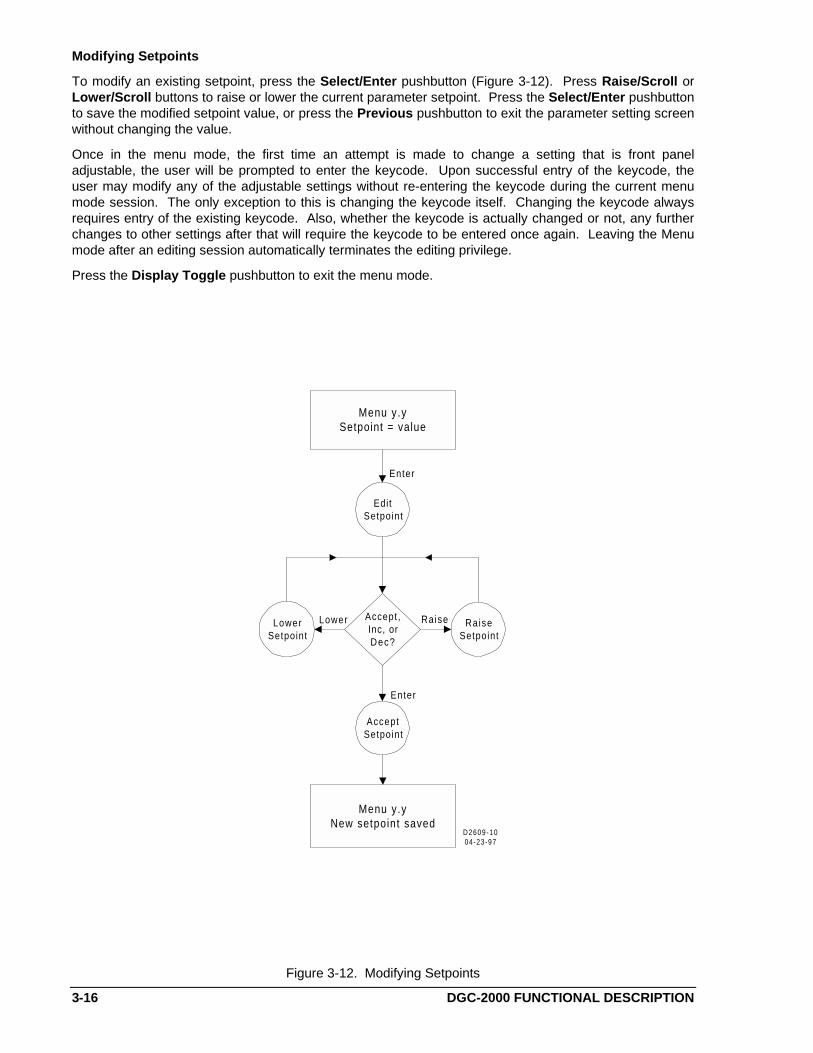
Modifying Setpoints
To modify an existing setpoint, press the Select/Enter pushbutton (Figure 3-12). Press Raise/Scroll orLower/Scroll buttons to raise or lower the current parameter setpoint. Press the Select/Enter pushbuttonto save the modified setpoint value, or press the Previous pushbutton to exit the parameter setting screenwithout changing the value.
Once in the menu mode, the first time an attempt is made to change a setting that is front paneladjustable, the user will be prompted to enter the keycode. Upon successful entry of the keycode, theuser may modify any of the adjustable settings without re-entering the keycode during the current menumode session. The only exception to this is changing the keycode itself. Changing the keycode alwaysrequires entry of the existing keycode. Also, whether the keycode is actually changed or not, any furtherchanges to other settings after that will require the keycode to be entered once again. Leaving the Menumode after an editing session automatically terminates the editing privilege.
Press the Display Toggle pushbutton to exit the menu mode.
EditSetpoint
Accept,Inc, orDec?
LowerSetpoint
RaiseSetpoint
AcceptSetpoint
Menu y.ySetpoint = value
Menu y.yNew setpoint saved
Enter
RaiseLower
Enter
D2609-1004-23-97
Figure 3-12. Modifying Setpoints
DGC-2000 FUNCTIONAL DESCRIPTION 3-17
Alternate Display Mode
After pressing the Display/Toggle pushbutton to enter the alternate display mode, pressing theRaise/Scroll or Lower/Scroll pushbutton allows the user to scroll through the alternate display modescreens.
The quantities are displayed in the following order.
• OIL PRESSURE• COOLANT TEMPERATURE• FUEL LEVEL• BATTERY VOLTAGE• TOTAL KILOWATT LOAD• HOURS TO NEXT SERVICE• GENERATOR A-B VOLTAGE• GENERATOR B-C VOLTAGE ( 3-PHASE SENSING ONLY)• GENERATOR C-A VOLTAGE (3-PHASE SENSING ONLY)• GENERATOR A-N VOLTAGE (3-PHASE L-N SENSING)• GENERATOR B-N VOLTAGE (3-PHASE L-N SENSING)• GENERATOR C-N VOLTAGE (3-PHASE L-N SENSING)• BUS VOLTAGE• GENERATOR PHASE A CURRENT ( 3-PHASE SENSING ONLY)• GENERATOR PHASE B CURRENT ( 3-PHASE SENSING ONLY)• GENERATOR PHASE C CURRENT ( 3-PHASE SENSING ONLY)• PHASE A kVA ( 3-PHASE SENSING ONLY)• PHASE B kVA ( 3-PHASE SENSING ONLY)• PHASE C kVA ( 3-PHASE SENSING ONLY)• TOTAL kVA• GENERATOR PHASE A KILOWATTS ( 3-PHASE SENSING ONLY)• GENERATOR PHASE B KILOWATTS ( 3-PHASE SENSING ONLY)• GENERATOR PHASE C KILOWATTS ( 3-PHASE SENSING ONLY)• GENERATOR TOTAL KILOWATT-HOURS• GENERATOR POWER FACTOR• GENERATOR FREQUENCY• BUS FREQUENCY• TOTAL RUN HOURS• AIR BOX DAMPER STATUS• ENGINE SPEED
FACTORY KEY CODE SETTING
Factory preprogrammed key code setting.
1. Raise/Scroll2. Lower/Scroll3. Select/Enter4. Previous5. Display Toggle6. Enter7. Enter
3-18 DGC-2000 FUNCTIONAL DESCRIPTION
ALLOWABLE KEY CODE PUSHBUTTONS
User key codes are one to eight presses of any of the following acceptable pushbuttons in any order,except Previous twice consecutively. When used, the key code must be followed by two presses of theSelect/Enter pushbutton.
• Raise/Scroll• Lower/Scroll• Select/Enter• Previous• Display/Toggle• Phase Toggle• Alarm Silence• Lamp Test
PARAMETERS AND DEFAULT SETTINGS
Front Panel Adjustable Parameters
All settings are viewable at the front panel. The following settings are adjustable at the front panel.
• Sensor failure alarm time delay From 1 to 10 seconds in 1 second increments• Metric conversion function ON or OFF• Low fuel prealarm level 10 to 100%• Precrank contact after cranking OPEN or CLOSED• Cool down time From 0 to 60 minutes in 5 minute increments• Precrank time delay From 0 to 30 seconds in 1 second increments
All Parameters
Specific parameters (settings) are not adjustable at either the front panel or through computercommunications. These settings are identified in the following list as (not adjustable). All otherparameters may be set through computer communications. Only those settings identified in the previousparagraph are adjustable at the front panel. The following list provides the parameters and the defaultsetting.
Metric Conversion (ON, OFF) default is OFFGenerator Connection (3-phaseL-L or 3-phaseL-N, 1-phaseA-B) default is 3-phaseL-N
Gen. PT Primary (1 - 15000 V) default is 480 VGen. PT Secondary (1 - 480 V) default is 480 VGen. CT Primary (1 - 5000 A) default is 500 ABus. PT Primary (1 - 15000 V) default is 480 VBus. PT Secondary (1 - 480 V) default is 480 VCooldown time (0 - 60 minutes) default is 0 minutesGenerator Speed Signal Sources = MPU/Alt/GenOverspeed Alarm:
Threshold (105 - 140%) default is 110%Activation Delay (10 - 500 milliseconds) default is 50 milliseconds
High Coolant Temperature Alarm:Threshold (100 - 280ºF) default is 275ºFArming Delay (not adjustable) is 60 seconds
High Coolant Temperature Prealarm is OFF:Threshold (100 - 280ºF) default is 250ºFArming Delay default is 60 seconds
Low Oil Pressure Alarm:Threshold (3 - 100 PSI) default is 15 PSIArming Delay (5 - 15 seconds) default is 10 seconds
DGC-2000 FUNCTIONAL DESCRIPTION 3-19
Low Oil Pressure Prealarm:Threshold (3 - 100 PSI) default is 25 PSIArming Delay (5 - 15 seconds) default is 10 seconds
Low Coolant Temperature Prealarm is OFF:Threshold (40 - 100 F) default is 50 FArming Delay (0 - 15 seconds) default is 0 seconds
Low Fuel Level Prealarm is OFF:Threshold (10 - 100 %) default is 25 %Activation Delay (not adjustable) is 0 seconds
Weak Battery PreAlarm is OFF:Threshold (4 - 8/8 - 16 V) default is 7.2/15.0 V (for 12/24 V systems)Activation Delay (1 - 10 seconds) default is 2 seconds
Low Battery Prealarm is OFF:Threshold (6 - 12/12 - 24 V) default is 9.0/20.0 V (for 12/24 V systems)Activation Delay (1 - 10 seconds) default is 10 seconds
Battery Overvoltage Prealarm is OFF:Threshold (14 - 16/24-32 V) default is 15.0/30.0 V (for 12/24 V systems)Activation Delay (not adjustable) is 0 seconds
Battery Charger Failure Prealarm is OFF:Activation Delay (not adjustable) is 0 seconds
Global Sender Failure Alarm Delay (1 - 10 seconds) default is 10 seconds:(This covers the oil pressure sender, generator sensing voltage, and speed signal sources)
Speed Signal Failure Alarm (ON, OFF) default is OFF.Oil Pressure Sender Failure Alarm (ON, OFF) default is OFF.Generator Sensing Voltage Failure Alarm (ON, OFF) default is OFF.Coolant Temperature Sender Failure Alarm (ON, OFF) default is OFF.
Arming Delay (5 - 30 minutes) default is 5 minutes(Global) Prealarm Buzzer default is ON.Maintenance Interval Prealarm:
Threshold (0 - 5000 hours) default is 500 hoursActivation Delay (not adjustable) is 0 hours
Engine KW Overload Prealarm is OFF:Threshold (95 - 140%) default is 105%Activation Delay (not adjustable) is 0 seconds
Cranking style (CONTINUOUS/CYCLE) is CYCLE# crank cycles (1 - 7 cycles) default is 2 cyclesCycle crank time (5 - 15 seconds) default is 5 secondsContinuous crank time (1 - 60 seconds) default is 10 secondsPrecrank delay (0 - 30 seconds) default is 0 secondsPrestart contact after crank disconnect is OFF (OPEN)
DGC-2000 INSTALLATION 4-1
SECTION 4 • INSTALLATION
GENERAL
DGC-2000 Digital Generator Controllers are delivered in sturdy cartons to prevent shipping damages.Upon receipt of the unit, check for damage, and if there is evidence of such, immediately file a claim withthe carrier and notify the Basler Electric Regional Sales Office, your Sales Representative or SalesRepresentative at Basler Electric, Highland, Illinois.
If the controller is not installed immediately, store it in the original shipping package in a moisture and dustfree environment.
HARDWARE
DGC-2000 Controllers are packaged in aluminum cases for improved electromagnetic compatibility andare suitable for mounting in any top mount enclosure. The metal case is resistant to moisture, salt fog,humidity, dust, dirt, and chemical contaminants. It also inhibits insect and rodent entrance. DGC-2000Controllers are mounted using the permanently attached 10-32 by 5/8 inch (1/2 inch usable) studs.
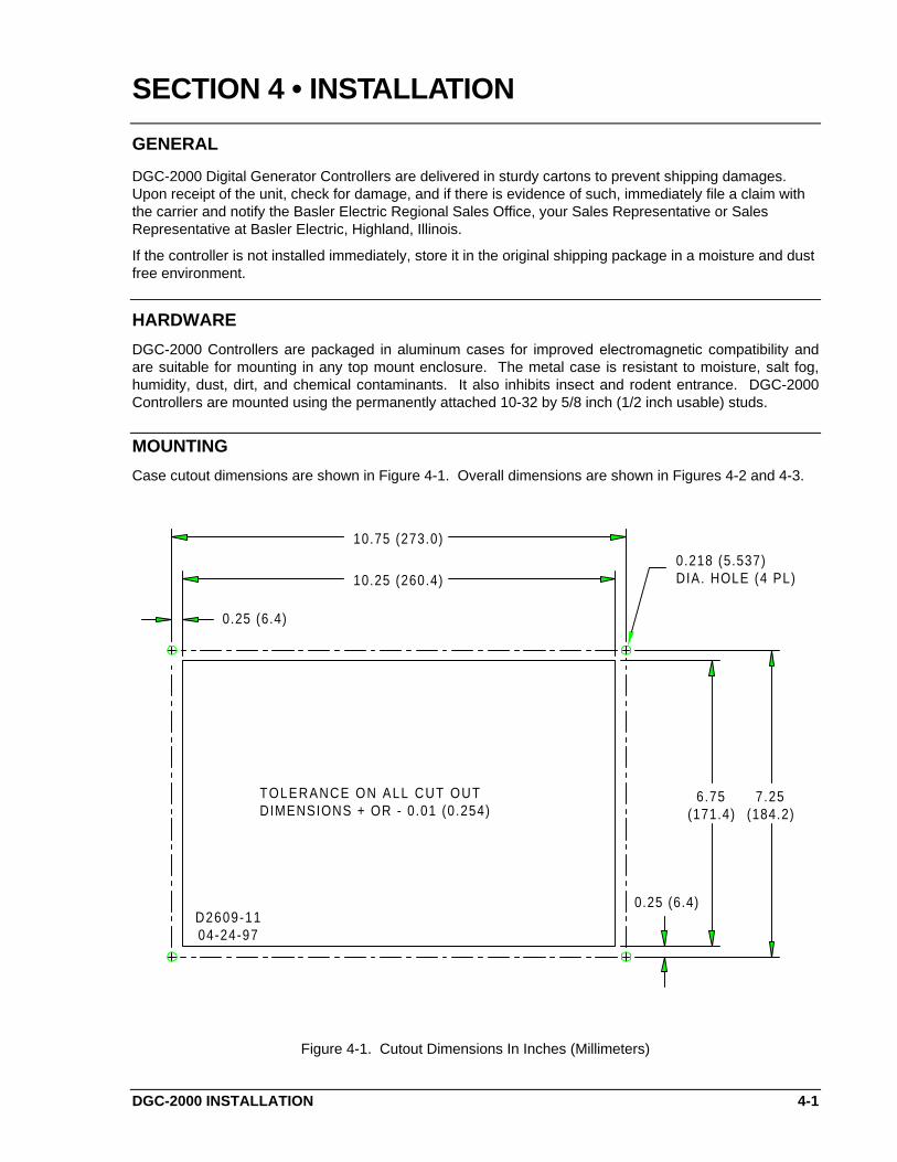
MOUNTING
Case cutout dimensions are shown in Figure 4-1. Overall dimensions are shown in Figures 4-2 and 4-3.
10.75 (273.0)
6.75(171.4)
0.25 (6.4)
10.25 (260.4)
0.25 (6.4)
7.25(184.2)
D2609-1104-24-97
0.218 (5.537)DIA. HOLE (4 PL)
TOLERANCE ON ALL CUT OUTDIMENSIONS + OR - 0.01 (0.254)
Figure 4-1. Cutout Dimensions In Inches (Millimeters)
4-2 DGC-2000 INSTALLATION
Not InAuto Alarm Load
Supplying
DGC 2000
Bas
ler
DigitalGensetController
R
-
GeneratorFrequency
GeneratorPhase
GeneratorA m p s
GeneratorVoltage
OilPressure
CoolantTemperature
BatteryVoltage Time
R u n
Raise
Scrol l
Lower
Scrol l
Select
EnterPrevious
Display
Toggle
Run Off Auto
Phase
Toggle
Alarm
Silence Test
Lamp
11.25(285.8)
7.75
10.13(257.18)
D2609-1206-12-97
(196.9)
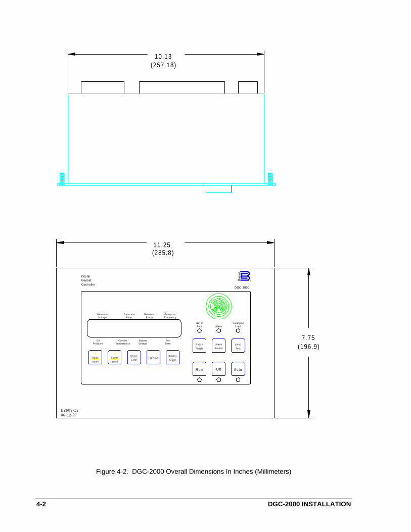
Figure 4-2. DGC-2000 Overall Dimensions In Inches (Millimeters)

DGC-2000 INSTALLATION 4-3
5 .72(146.1)
.37
4 .72(119.8)
(9.40)
(168.28)
6 .6 3
D 2 6 0 9 - 1 30 4 - 1 6 - 9 9
1 Amp 32 VdcEmergency Stop
Rated Current
10 Amps
OUTPUT CONTACT RATINGS:
Run, Master Start,Fuel Solenoid,Auxiliary Start
Low Oil Pressure,Overspeed, Air Damper,Overcrank, Alarm,Pre-Start, Pre-Alarm,High Coolant Temp,Low Coolant Temp
30 Vdc 2 Amps
24 Vdc
Rated VoltageContact
100 - 480 Vac Nominal, 50/60 Hz @ < 1 VA/Phase
Max Voltage
Alternator Stator Sensing Input:
Resistance 0 - 250 Ohms Nominal
Resistance 0 - 250 Ohms Nominal
625 Hz - 10 kHz Nominal2 Vac During Cranking
100 - 900 Hz Nominal12/24 Vdc Nominal System
Oil Pressure Sending Unit Input:
Fuel Level Sending Unit Input:
Magnetic Pick Up Input:
INPUT CONTACT SENSING:
Battery Charger,ATS, Air Damper,
Resistance 0 - 1000 Ohms Nominal
Coolant Level
Coolant Temperature Sending Unit Input:
2 mA
Max CurrentInput
32 Vdc
INPUTS:
(618) 654-2341
1 or 5 Amp 50/60 Hz @ < 1 VA/Phase
12/24 Vdc Nominal @ 12 Watts
Current Sensing Input:
Voltage Sensing Input:
Power Input:
R
R
Figure 4-3. DGC-2000 Overall Dimensions In Inches (Millimeters)
CONNECTIONS
Incorrect wiring may result in damage to the controller.
WARNING!If the air damper is functional, an auxiliary contact from the Emergency Stop switch mustbe used to trip the air damper solenoid.
CAUTION
Be sure the controller battery input polarity is wired correctly. Reverse polarity batterypower will damage the controller.
NOTE
Be sure the controller is hard-wired to earth ground with no smaller than 12 AWG copperwire attached to the ground terminal on the rear of the controller case
Except as noted above, connections should be made with minimum wire size of 14 AWG. Be sure to usethe correct input power for the power supply. Figure 4-4 is a typical ac connection diagram for directconnected single-phase sensing system. Figure 4-5 is a typical ac connection diagram for directconnected three-phase line to line sensing system. Figure 4-6 is a typical ac connection diagram for directconnected three-phase line to neutral sensing system.
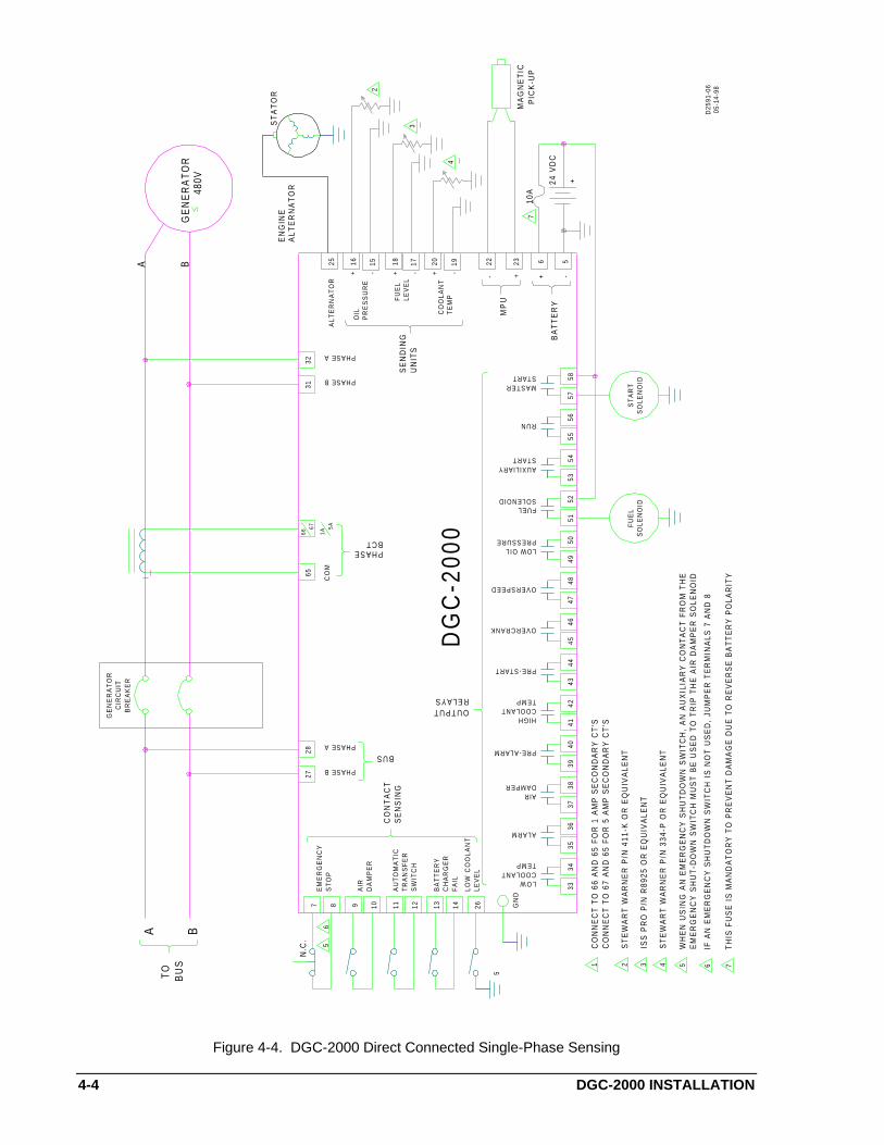
4-4 DGC-2000 INSTALLATION
1413121110987
LOWCOOLANTTEMP
ALARM
AIRDAMPER
PRE-ALARM
HIGHCOOLANTTEMP
PRE-START
OVERCRANK
OVERSPEED
LOW OILPRESSURE
FUELSOLENOID
AUXILIARYSTART
RUN
MASTERSTART
GE
NE
RA
TO
RC
IRC
UIT
BR
EA
KE
R
2728
6531
3267
66
ST
AR
TS
OLE
NO
IDS
OLE
NO
IDF
UE
L
3334
3536
3738
3940
4142
4344
4546
4748
4950
5152
5354
5556
5758
EM
ER
GE
NC
YS
TO
P
AIR
DA
MP
ER
AU
TO
MA
TIC
TR
AN
SF
ER
SW
ITC
H
BA
TT
ER
YC
HA
RG
ER
FA
IL
GN
D
CO
NT
AC
TS
EN
SIN
G
PHASE B
BUSPHASE A
OUTPUTRELAYS
BCTPHASE
CO
M5A
1A
PHASE B
PHASE A
SE
ND
ING
UN
ITS
GE
NE
RA
TO
R
A B
6
DG
C-2
000
A B
TO
BU
S
N.C
.
1C
ON
NE
CT
TO
66
AN
D 6
5 F
OR
1 A
MP
SE
CO
ND
AR
Y C
T'S
CO
NN
EC
T T
O 6
7 A
ND
65
FO
R 5
AM
P S
EC
ON
DA
RY
CT
'S
ST
EW
AR
T W
AR
NE
R P
/N 4
11-K
OR
EQ
UIV
ALE
NT
2
ISS
PR
O P
/N R
8925
OR
EQ
UIV
ALE
NT
3
ST
EW
AR
T W
AR
NE
R P
/N 3
34-P
OR
EQ
UIV
ALE
NT
4
48
0V
D25
91-0
605
-14-
98
WH
EN
US
ING
AN
EM
ER
GE
NC
Y S
HU
TD
OW
N S
WIT
CH
, A
N A
UX
ILIA
RY
CO
NT
AC
T F
RO
M T
HE
EM
ER
GE
NC
Y S
HU
T-D
OW
N S
WIT
CH
MU
ST
BE
US
ED
TO
TR
IP T
HE
AIR
DA
MP
ER
SO
LEN
OID
5
IF A
N E
ME
RG
EN
CY
SH
UT
DO
WN
SW
ITC
H I
S N
OT
US
ED
, JU
MP
ER
TE
RM
INA
LS 7
AN
D 8
6
TH
IS F
US
E I
S M
AN
DA
TO
RY
TO
PR
EV
EN
T D
AM
AG
E D
UE
TO
RE
VE
RS
E B
AT
TE
RY
PO
LAR
ITY
7
525 16 18 20
OIL
PR
ES
SU
RE
FU
EL
LEV
EL
CO
OL
AN
TT
EM
P
22 23
- +
MP
U
6 5
BA
TT
ER
Y
10A
-+
ALT
ER
NA
TO
R
24 V
DC
+
15 17 19-+-+-+
7
4
3
2
MA
GN
ET
ICP
ICK
-UP
ST
AT
OR
ALT
ER
NA
TO
RE
NG
INE
26L
OW
CO
OL
AN
TLE
VE
L
5
Figure 4-4. DGC-2000 Direct Connected Single-Phase Sensing
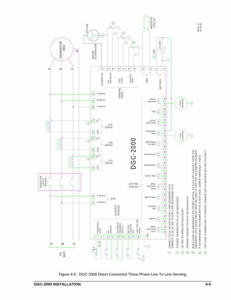
DGC-2000 INSTALLATION 4-5
1413121110987
LOWCOOLANTTEMP
ALARM
AIRDAMPER
PRE-ALARM
HIGHCOOLANTTEMP
PRE-START
OVERCRANK
OVERSPEED
LOW OILPRESSURE
FUELSOLENOID
AUXILIARYSTART
RUN
MASTERSTART
GE
NE
RA
TO
RC
IRC
UIT
BR
EA
KE
R
2728
6265
6830
3132
6364
6766
7069
ST
AR
TS
OLE
NO
IDS
OLE
NO
IDF
UE
L
3334
3536
3738
3940
4142
4344
4546
4748
4950
5152
5354
5556
5758
EM
ER
GE
NC
YS
TO
P
AIR
DA
MP
ER
AU
TO
MA
TIC
TR
AN
SF
ER
SW
ITC
H
BA
TT
ER
YC
HA
RG
ER
FA
IL
GN
D
CO
NT
AC
TS
EN
SIN
G
PHASE B
BUSPHASE A
OUTPUTRELAYS
CO
M1A
5A
PHASECCT
BCTPHASE
CO
M5A
1A
ACTPHASE
CO
M5A
1A
PHASE C
PHASE B
PHASE A
UN
ITS
GE
NE
RA
TO
R
A B C
N
11
1
DG
C-2
000
A B C
TO
BU
S
N.C
.
1C
ON
NE
CT
TO
63,
66
AN
D 6
9 F
OR
1 A
MP
SE
CO
ND
AR
Y C
T'S
CO
NN
EC
T T
O 6
4, 6
7 A
ND
70
FO
R 5
AM
P S
EC
ON
DA
RY
CT
'S
ST
EW
AR
T W
AR
NE
R P
/N 4
11-K
OR
EQ
UIV
ALE
NT
2
ISS
PR
O P
/N R
8925
OR
EQ
UIV
ALE
NT
3
ST
EW
AR
T W
AR
NE
R P
/N 3
34-P
OR
EQ
UIV
ALE
NT
4
48
0V
WH
EN
US
ING
AN
EM
ER
GE
NC
Y S
HU
TD
OW
N S
WIT
CH
, A
N A
UX
ILIA
RY
CO
NT
AC
T F
RO
M T
HE
EM
ER
GE
NC
Y S
HU
T-D
OW
N S
WIT
CH
MU
ST
BE
US
ED
TO
TR
IP T
HE
AIR
DA
MP
ER
SO
LEN
OID
5
IF A
N E
ME
RG
EN
CY
SH
UT
DO
WN
SW
ITC
H I
S N
OT
US
ED
, JU
MP
ER
TE
RM
INA
LS 7
AN
D 8
6
TH
IS F
US
E I
S M
AN
DA
TO
RY
TO
PR
EV
EN
T D
AM
AG
E D
UE
TO
RE
VE
RS
E B
AT
TE
RY
PO
LAR
ITY
7
D2
59
1-0
505
-14-
98
56
25 16 18 20
OIL
PR
ES
SU
RE
FU
EL
LEV
EL
CO
OL
AN
TT
EM
P
22 23
- +
MP
U
6 5B
AT
TE
RY
10A
-+
ALT
ER
NA
TO
R
24 V
DC
+
15 17 19-+-+-+
7
4
3
2
MA
GN
ET
ICP
ICK
-UP
ST
AT
OR
ALT
ER
NA
TO
RE
NG
INE
5
26L
OW
CO
OL
AN
TLE
VE
L
SE
ND
ING
Figure 4-5. DGC-2000 Direct Connected Three-Phase Line To Line Sensing

4-6 DGC-2000 INSTALLATION
1413121110987
LOWCOOLANTTEMP
ALARM
AIRDAMPER
PRE-ALARM
HIGHCOOLANTTEMP
PRE-START
OVERCRANK
OVERSPEED
LOW OILPRESSURE
FUELSOLENOID
AUXILIARYSTART
RUN
MASTERSTART
GE
NE
RA
TO
RC
IRC
UIT
BR
EA
KE
R
2728
6265
6829
3031
3263
6467
6670
69
ST
AR
TS
OLE
NO
IDS
OLE
NO
IDF
UE
L
3334
3536
3738
3940
4142
4344
4546
4748
4950
5152
5354
5556
5758
EM
ER
GE
NC
YS
TO
P
AIR
DA
MP
ER
AU
TO
MA
TIC
TR
AN
SF
ER
SW
ITC
H
BA
TT
ER
YC
HA
RG
ER
FA
IL
GN
D
CO
NT
AC
TS
EN
SIN
G
PHASE B
BUSPHASE A
OUTPUTRELAYS
CO
M1A
5A
PHASECCT
BCTPHASE
CO
M5A
1A
ACTPHASE
CO
M5A
1A
NEUTRAL
PHASE C
PHASE B
PHASE A
GE
NE
RA
TO
R
A B C
N
11
1
DG
C-2
000
A B C
TO
BU
S
N.C
.
1C
ON
NE
CT
TO
63,
66
AN
D 6
9 F
OR
1 A
MP
SE
CO
ND
AR
Y C
T'S
CO
NN
EC
T T
O 6
4, 6
7 A
ND
70
FO
R 5
AM
P S
EC
ON
DA
RY
CT
'S
ST
EW
AR
T W
AR
NE
R P
/N 4
11-K
OR
EQ
UIV
ALE
NT
2
ISS
PR
O P
/N R
8925
OR
EQ
UIV
ALE
NT
3
ST
EW
AR
T W
AR
NE
R P
/N 3
34-P
OR
EQ
UIV
ALE
NT
4
48
0V
D25
91-0
405
-14-
98
WH
EN
US
ING
AN
EM
ER
GE
NC
Y S
HU
TD
OW
N S
WIT
CH
, A
N A
UX
ILIA
RY
CO
NT
AC
T F
RO
M T
HE
EM
ER
GE
NC
Y S
HU
T-D
OW
N S
WIT
CH
MU
ST
BE
US
ED
TO
TR
IP T
HE
AIR
DA
MP
ER
SO
LEN
OID
5
IF A
N E
ME
RG
EN
CY
SH
UT
DO
WN
SW
ITC
H I
S N
OT
US
ED
, JU
MP
ER
TE
RM
INA
LS 7
AN
D 8
6
TH
IS F
US
E I
S M
AN
DA
TO
RY
TO
PR
EV
EN
T D
AM
AG
E D
UE
TO
RE
VE
RS
E B
AT
TE
RY
PO
LAR
ITY
7
56
25 16 18 20 22 23
- +
MP
U
6 5B
AT
TE
RY
10A
-+
ALT
ER
NA
TO
R
24 V
DC
+
15 17 19-+-+-+
7
4
3
2
MA
GN
ET
ICP
ICK
-UP
ST
AT
OR
ALT
ER
NA
TO
RE
NG
INE
SE
ND
ING
UN
ITS
OIL
PR
ES
SU
RE
FU
EL
LEV
EL
CO
OL
AN
TT
EM
P
26L
OW
CO
OL
AN
TLE
VE
L
5
Figure 4-6. DGC-2000 Direct Connected Three-Phase Line To Neutral Sensing

DGC-2000 INSTALLATION 4-7
COMMUNICATION CONNECTORS AND SETTINGS
RS-232 Connector
The RS-232 connector is a DB-9 female connector. Connector pin numbers, functions, names, and signaldirections are shown in Table 4-1. Figure 4-7 provides the RS-232 cable connection diagram.
Table 4-1. RS-232 Pinouts
Pin Function Name Direction
1 N/C ---- N/A
2 Transmit Data (TXD) From DGC-2000
3 Receive Data (RXD) Into DGC-2000
4 N/C ---- N/A
5 Signal Ground (GND) N/A
6 N/C ---- N/A
7 N/C ---- N/A
8 N/C ---- N/A
9 N/C ---- N/A
5
4
3
2
1 1
2
3
4
5
RXD
TXD
S G N D
TXD
RXD
N.C.
S G N D
FEMALE DB-9MALE DB-9
D2610-0105-15-97
9
6
7
8
N.C.
N.C.
TO DGC20009-PIN PC-AT
N.C.
N.C.
N.C.
Figure 4-7. Personal Computer To DGC-2000
Communication Settings
Communication settings are the formal set of conventions controlling the format and relative timing ofmessage exchange between two communications terminals. Default settings baud rate = 9600, parity =None, and stop bits = 1.
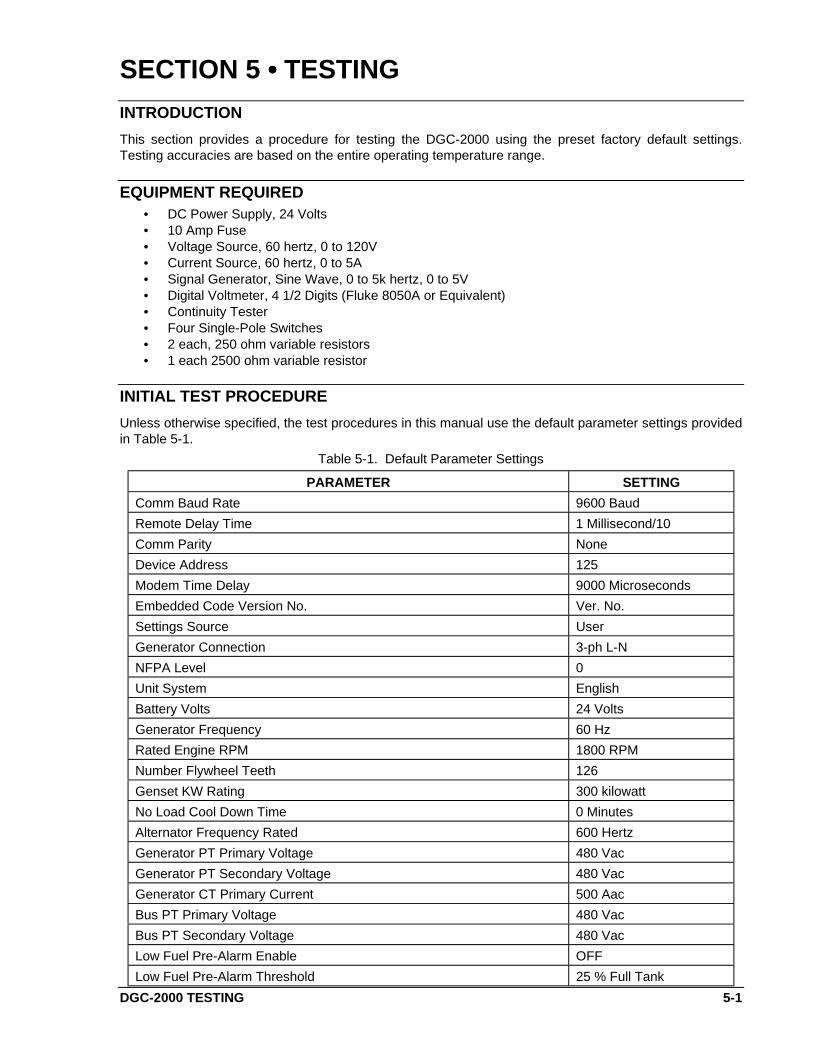
DGC-2000 TESTING 5-1
SECTION 5 •••• TESTING
INTRODUCTION
This section provides a procedure for testing the DGC-2000 using the preset factory default settings.Testing accuracies are based on the entire operating temperature range.
EQUIPMENT REQUIRED• DC Power Supply, 24 Volts• 10 Amp Fuse• Voltage Source, 60 hertz, 0 to 120V• Current Source, 60 hertz, 0 to 5A• Signal Generator, Sine Wave, 0 to 5k hertz, 0 to 5V• Digital Voltmeter, 4 1/2 Digits (Fluke 8050A or Equivalent)• Continuity Tester• Four Single-Pole Switches• 2 each, 250 ohm variable resistors• 1 each 2500 ohm variable resistor
INITIAL TEST PROCEDURE
Unless otherwise specified, the test procedures in this manual use the default parameter settings providedin Table 5-1.
Table 5-1. Default Parameter Settings
PARAMETER SETTING
Comm Baud Rate 9600 Baud
Remote Delay Time 1 Millisecond/10
Comm Parity None
Device Address 125
Modem Time Delay 9000 Microseconds
Embedded Code Version No. Ver. No.
Settings Source User
Generator Connection 3-ph L-N
NFPA Level 0
Unit System English
Battery Volts 24 Volts
Generator Frequency 60 Hz
Rated Engine RPM 1800 RPM
Number Flywheel Teeth 126
Genset KW Rating 300 kilowatt
No Load Cool Down Time 0 Minutes
Alternator Frequency Rated 600 Hertz
Generator PT Primary Voltage 480 Vac
Generator PT Secondary Voltage 480 Vac
Generator CT Primary Current 500 Aac
Bus PT Primary Voltage 480 Vac
Bus PT Secondary Voltage 480 Vac
Low Fuel Pre-Alarm Enable OFF
Low Fuel Pre-Alarm Threshold 25 % Full Tank

5-2 DGC-2000 TESTING
PARAMETER SETTING
Low Coolant Temperature Pre-Alarm Enable OFF
Low Coolant Temperature Pre-Alarm Threshold 50 Degrees F
Battery Overvoltage Pre-Alarm Enable OFF
Battery Overvoltage Pre-Alarm Threshold 30.0 VDC
Maintenance Interval Pre-Alarm Enable OFF
Maintenance Interval Pre-Alarm Threshold 500 Hours
Engine KW Overload Pre-Alarm Enable OFF
Engine KW Overload Pre-Alarm Threshold 105 % of Rated
High Coolant Temperature Pre-Alarm Enable ON
High Coolant Temperature Pre-Alarm Threshold 250 Degrees F
Low Oil Pressure Pre-Alarm Enable ON
Low Oil Pressure Pre-Alarm Threshold 25 PSI
Low Battery Voltage Pre-Alarm Enable OFF
Low Battery Voltage Pre-Alarm Threshold 20.0 VDC
Low Battery Voltage Pre-Alarm Activation Time Delay 10 Seconds
Weak Battery Pre-Alarm Enable OFF
Weak Battery Pre-Alarm Threshold 15.0 VDC
Weak Battery Pre-Alarm Activation Time Delay 2 Seconds
High Coolant Temperature Alarm Enable ON
High Coolant Temperature Alarm Threshold 275 Degrees F
High Coolant Temperature Alarm Arming Delay After Crank Disconnect 60 Seconds
Low Oil Pressure Alarm Enable ON
Low Oil Pressure Alarm Threshold 15 PSI
Low Oil Pressure Alarm Arming Delay After Crank Disconnect 10 Seconds
Overspeed Alarm Enable ON
Overspeed Alarm Threshold 110% of Rated
Overspeed Alarm Activation Time Delay 50 Millisecond
Coolant Temperature Sender Failure Alarm Enable OFF
Oil Pressure Sender Failure Alarm Enable OFF
Speed Failure Alarm Enable OFF
Loss of Generator Voltage Alarm Enable OFF
Pre-Alarm Buzzer Enable ON
Battery Charger Failure Pre-Alarm Enable OFF
Global Sender Failure Alarm Time Delay 10 Seconds
Coolant Temp. Sender Failure Alarm Activation Time Delay 5 Minutes
Cranking Style Cycle
Number of Crank Cycles 2
Cycle Crank Time 5 Seconds
Continuous Crank Time 10 Seconds
Crank Disconnect Limit 30 % of Rated
Pre-Crank Delay 0 Seconds
Pre-crank Contact After Crank Disconnect Open
Generator Speed Mode MPU/ALT/GEN
Generator Rotation A-B-C

DGC-2000 TESTING 5-3
Step 1. Connect the DGC-2000 test setup as shown in Figure 5-1.
Step 2. Apply operating voltage to battery voltage terminals.
Result: The LCD displays DGC 2000 and the software version for approximately one secondbefore switching to the normal display mode and at the same time, the Alarm sounds. Theaudible alarm will sound continuously when Not In Auto or in Alarm. The audible alarm may besilenced by pressing the Alarm Silence switch on the front panel.
Step 3 Press the Off switch to place the DGC-2000 in the OFF position.
Step 4. Verify that LEDs Not In Auto and Off are ON, the Alarm LED is flashing, and the LCD backlight isON with system parameters displayed.
Step 5. Press the Lamp Test switch and verify that all six LEDs are ON (Not In Auto, Alarm, and Off arered; Supplying Load, Run, and Auto are green). All LCD pixels should be visible.
Step 6. Verify Run, Off, and Auto switches, along with their respective LEDs, toggle as each switch isoperated. Not In Auto LED should be OFF when Auto is selected.
Step 7. Verify that switches Raise/Scroll, Lower/Scroll, Select/Enter, Previous, and Display/Toggle arefunctional by scrolling through the unit menus.
METERING TEST PROCEDURES
Metering Battery And Generator Voltages
NOTEDisplayed voltage is equal to the generator potential transformer primary voltage settingtimes the applied voltage divided by the generator potential transformer secondaryvoltage setting.
Step 1. Verify that the battery input (terminals 5 and 6) voltage is 24.0 Vdc.
Step 2. Verify that the DGC-2000 displayed value is 24.0 ±0.5 Vdc.
Step 3. Apply 120.0 Vac, 60.0 hertz to phase A (line to neutral) generator voltage input (terminals 32 and29).
Step 4. Verify that the DGC-2000 generator frequency displayed value is 60.0 ±0.2 hertz.
Step 5. Verify that the DGC-2000 phase A to neutral voltage displayed value is 120.0 ±2.0 Vac.
Step 6. Remove the voltage.
Step 7. Apply 120.0 Vac, 60.0 hertz to phases A and B generator voltage input (terminals 32 and 31).
Step 8. Verify that the DGC-2000 generator A to B voltage displayed value is 120.0 ±2.0 Vac.
Step 9. Remove the voltage.
Step 10. Apply 120.0 Vac, 60.0 hertz (line to neutral) to phase B generator voltage input (terminals 31 and29).
Step 11. Verify that the DGC-2000 line to neutral voltage displayed value is 120.0 ±2.0 Vac.
Step 12. Remove the voltage.
Step 13. Apply 120.0 Vac, 60.0 hertz to phases B and C generator voltage input (terminals 31 and 30).
Step 14. Verify that the DGC-2000 generator B to C voltage displayed value is 120.0 ±2.0 Vac.
Step 15. Remove the voltage.
Step 16. Apply 120.0 Vac, 60.0 hertz (line to neutral) to phase C generator voltage input (terminals 30 and29).
Step 17. Verify that the DGC-2000 line to neutral voltage displayed value is 120.0 ±2.0 Vac.
Step 18. Remove the voltage.
Step 19. Apply 120.0 Vac, 60.0 hertz to phases C and A generator voltage input (terminals 30 and 32).
Step 20. Verify that the DGC-2000 generator C to A voltage displayed value is 120.0 ±2.0 Vac.
Step 21. Remove the voltage.

5-4 DGC-2000 TESTING
14
13
12
11
10987
LOWCOOLANTTEMP
ALARM
AIRDAMPER
PRE-ALARM
HIGHCOOLANTTEMP
PRE-START
OVERCRANK
OVERSPEED
LOW OILPRESSURE
FUELSOLENOID
AUXILIARYSTART
RUN
MASTERSTART
27
28
62
65
68
29
30
31
32
6364
6766
7069
33
34
35
36
37
38
39
40
41
42
43
44
45
46
47
48
49
50
51
52
53
54
55
56
57
58
EM
ER
GE
NC
YS
TO
P
AIR
DA
MP
ER
AU
TO
MA
TIC
TR
AN
SF
ER
SW
ITC
H
BA
TT
ER
YC
HA
RG
ER
FA
IL
GN
D
CO
NT
AC
TS
EN
SIN
GPHASE B
BU
S V
OL
TA
GE
PHASE A OU
TP
UT
RE
LA
YS
CO
M1A
5A
PH
AS
E C
C
T
CO
M5A
1AC
OM
5A1A
NEUTRAL
PHASE C
PHASE B
PHASE A
25
16
18
20
OIL
PR
ES
SU
RE
FU
EL
LE
VE
L
CO
OL
AN
T T
EM
P
SE
ND
ING
UN
ITS
22
23
- +
MP
U
6 5
BA
TT
ER
Y
10A
SIG
NA
L G
EN
ER
AT
OR
0-5
kHZ
, 0-
5 V
AC
-+
DG
C-2
000
N.C
.
AL
TE
RN
AT
OR
D2
59
1-0
905
-14-
98
PH
AS
E B
C
TP
HA
SE
A
CT
GE
N V
OL
TA
GE
CL
OS
ED
OP
EN
OP
EN
OP
EN
250
OH
MS
(S
ET
TO
60
OH
MS
)
250
OH
MS
(S
ET
TO
100
OH
MS
)
2500
OH
MS
(SE
T T
O 1
00 O
HM
S)
24 V
DC
+
15
17
19
-+-+-+
26
LO
W C
OO
LA
NT
LE
VE
LO
PE
N
5
Figure 5-1. Test Set Diagram
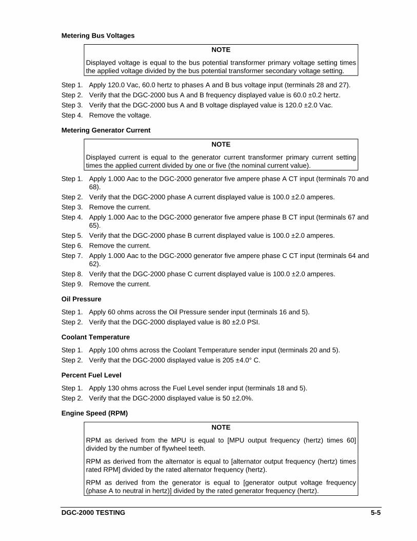
DGC-2000 TESTING 5-5
Metering Bus Voltages
NOTE
Displayed voltage is equal to the bus potential transformer primary voltage setting timesthe applied voltage divided by the bus potential transformer secondary voltage setting.
Step 1. Apply 120.0 Vac, 60.0 hertz to phases A and B bus voltage input (terminals 28 and 27).
Step 2. Verify that the DGC-2000 bus A and B frequency displayed value is 60.0 ±0.2 hertz.
Step 3. Verify that the DGC-2000 bus A and B voltage displayed value is 120.0 ±2.0 Vac.
Step 4. Remove the voltage.
Metering Generator Current
NOTE
Displayed current is equal to the generator current transformer primary current settingtimes the applied current divided by one or five (the nominal current value).
Step 1. Apply 1.000 Aac to the DGC-2000 generator five ampere phase A CT input (terminals 70 and68).
Step 2. Verify that the DGC-2000 phase A current displayed value is 100.0 ±2.0 amperes.
Step 3. Remove the current.
Step 4. Apply 1.000 Aac to the DGC-2000 generator five ampere phase B CT input (terminals 67 and65).
Step 5. Verify that the DGC-2000 phase B current displayed value is 100.0 ±2.0 amperes.
Step 6. Remove the current.
Step 7. Apply 1.000 Aac to the DGC-2000 generator five ampere phase C CT input (terminals 64 and62).
Step 8. Verify that the DGC-2000 phase C current displayed value is 100.0 ±2.0 amperes.
Step 9. Remove the current.
Oil Pressure
Step 1. Apply 60 ohms across the Oil Pressure sender input (terminals 16 and 5).
Step 2. Verify that the DGC-2000 displayed value is 80 ±2.0 PSI.
Coolant Temperature
Step 1. Apply 100 ohms across the Coolant Temperature sender input (terminals 20 and 5).
Step 2. Verify that the DGC-2000 displayed value is 205 ±4.0° C.
Percent Fuel Level
Step 1. Apply 130 ohms across the Fuel Level sender input (terminals 18 and 5).
Step 2. Verify that the DGC-2000 displayed value is 50 ±2.0%.
Engine Speed (RPM)
NOTE
RPM as derived from the MPU is equal to [MPU output frequency (hertz) times 60]divided by the number of flywheel teeth.
RPM as derived from the alternator is equal to [alternator output frequency (hertz) timesrated RPM] divided by the rated alternator frequency (hertz).
RPM as derived from the generator is equal to [generator output voltage frequency(phase A to neutral in hertz)] divided by the rated generator frequency (hertz).
5-6 DGC-2000 TESTING
Step 1. Apply a 5 Vac, 3780 hertz sine wave to the DGC-2000 magnetic pickup unit inputs (terminals 23and 22).
Step 2. Verify that the DGC-2000 displayed value is 1800 ±36 RPM.
Step 3. Remove the voltage.
Generator Power Factor
NOTE
The DGC-2000 uses phase A voltage and phase B current for Power Factor calculations.Therefore, if this test is performed with the current lagging the voltage by 120 degrees.,the displayed Power Factor will be approximately 1.00.
Step 1. Apply 120 Vac to phase A to neutral generator voltage inputs (terminals 32 and 29).
Step 2. Apply 1.0 Aac to phase B current transformer inputs (terminals 67 and 65) in phase with thephase A to neutral voltage.
Step 3. Verify that the DGC-2000 displayed value is -0.50 ±0.02.
Step 4. Remove voltage and current.
Generator kW And kVA
NOTE
The displayed kW is equal to the kVA times the Power Factor.
Step 1. Apply in parallel 120 Vac to phase A to neutral (terminals 32 and 29), phase B to neutral(terminals 31 and 29), and phase C to neutral (terminals 30 and 29).
Step 2. Apply in series and in phase with the voltage 1 Aac to Phase A current transformer input(terminals 69 and 68), Phase B current transformer input (terminals 66 and 65), and Phase Ccurrent transformer input (terminals 63 and 62).
Step 3. Verify that the DGC-2000 displayed value for individual phase kW is -30 ±2 kW.
Step 4. Verify that the DGC-2000 displayed value for total kW is -90 ±2 kW.
Step 5. Verify that the DGC-2000 displayed value for individual phase kVA is 60 ±2 kVA.
Step 6. Verify that the DGC-2000 displayed value for total kVA is within 180 ±5 kVA.
Step 7. Remove voltage and current.
CRANKING TEST PROCEDURES
Crank Cycle
NOTE
The DGC will go into Overcrank if the Off switch is not pressed before two crank cyclesexpire. Pressing Off will reset this condition if it occurs.
Step 1. Verify that all output contacts are open.
Step 2. Press the Run switch on the front panel.
Step 3. Verify that the DGC-2000 displays CRANKING STATUS.
Step 4. Verify that only the Master Start, Auxiliary Start, Fuel Solenoid, and Pre-Start output contacts areclosed during CRANKING CYCLE.
Step 5. Verify that only the Pre-Start contact remains closed during RESTING.
Step 6. Press the Off switch on the front panel.
Step 7. Press the Auto switch on the front panel.
Step 8. Apply a contact closure across the Automatic Transfer Switch inputs (terminals 11 and 12).
Step 9. Verify that the DGC-2000 displays CRANKING STATUS.
Step 10. Verify that only the Master Start, Auxiliary Start, Fuel Solenoid, and Pre-Start output contacts areclosed during CRANKING CYCLE.
DGC-2000 TESTING 5-7
Step 11. Verify that only the Pre-Start contact remains closed during RESTING.
Step 12. Press the Off switch on the front panel.
Step 13. Open the contact across the Automatic Transfer Switch inputs.
Running
Step 1. Press the Run switch on the front panel.
Step 2. Within 5 seconds of beginning cranking, apply in parallel 120 Vac to phase A to neutral (terminals32 and 29), phase B to neutral (terminals 31 and 29), and phase C to neutral (terminals 30 and29).
Step 3. Verify that only the Run and Fuel Solenoid output contacts are closed.
Step 4. Verify that the DGC-2000 normal mode display now meters the active generator values listed onthe front panel instead of displaying READY.
Step 5. Press the Off switch on the front panel.
Step 6. Remove the voltage.
Step 7. Press the Auto switch on the front panel.
Step 8. Apply a contact closure across the Automatic Transfer Switch inputs (terminals 11 and 12).
Step 9. Within 5 seconds of beginning cranking, apply in parallel 120 Vac to phase A to neutral (terminals32 and 29), phase B to neutral (terminals 31 and 29), and phase C to neutral (terminals 30 and29).
Step 10. Verify that only the Run and Fuel Solenoid output contacts are closed.
Step 11. Verify that the DGC-2000 normal mode display now meters the active generator values listed onthe front panel instead of displaying READY.
Step 12. Press the Off switch on the front panel.
Step 13. Remove the voltage.
Step 14. Open the contact across the Automatic Transfer Switch inputs.
PROTECTIVE FUNCTIONS
Overcrank
Step 1. Press the Run switch on the front panel.
Step 2. Verify that after two cycles the DGC-2000 display indicates GEN OVER-CRANK ALARM andthat only the Alarm, Air Damper, and Overcrank output contacts are closed.
Step 3. Press the Off switch on the front panel and verify that the DGC-2000 resets to the Ready modeand that all output contacts open.
Overspeed
Step 1. Apply in parallel 120 Vac to phase A to neutral (terminals 32 and 29), phase B to neutral(terminals 31 and 29), and phase C to neutral (terminals 30 and 29).
Step 2. Apply a 5 Vac, 4000 hertz sine wave to the DGC-2000 MPU inputs (terminals 23 and 22).
Step 3. Press the Run switch on the front panel.
Step 4. Slowly increase the frequency to the DGC-2000 MPU input until an overspeed shutdown occurs.
Step 5. Verify shutdown occurs within 4158 ±83 hertz (1980 ±38 RPM).
Step 6. Verify that the DGC-2000 display indicates GEN OVERSPEED ALARM and that only the Alarm,Air Damper, and Overspeed output contacts are closed.
Step 7. Remove the voltages.
Step 8. Press the Off switch on the front panel and verify that the DGC-2000 resets to the Ready modeand that all output contacts open.
Low Oil Pressure
Step 1. Apply in parallel 120 Vac to phase A to neutral (terminals 32 and 29), phase B to neutral(terminals 31 and 29), and phase C to neutral (terminals 30 and 29).
5-8 DGC-2000 TESTING
Step 2. Press the Run switch on the front panel.
Step 3. Wait ten seconds after crank disconnect. Increase the resistance across the Oil Pressure senderinput (terminals 16 and 5) until a Pre-Alarm occurs.
Step 4. Verify that the DGC-2000 display value is 25 ±2 PSI when Pre-Alarm occurs.
Step 5. Verify that the DGC-2000 displays an alternately flashing dark field in the oil pressure locationand that the Pre-Alarm output contact has closed.
Step 6. While monitoring displayed oil pressure, further increase the resistance across the Oil Pressuresender input until a low oil pressure shutdown occurs.
NOTE
Oil Pressure displayed value is 0 below 15 PSI.
Step 7. Verify that the DGC-2000 displayed value is within 0 to 17 PSI when shutdown occurs.
Step 8. Verify that the DGC-2000 display indicates LOW OIL PRESSURE ALARM and that only theAlarm, Air Damper, and Low Oil Pressure output contacts are closed.
Step 9. Remove the voltage and return the resistance to 60 ohms.
Step 10. Press the Off switch on the front panel and verify that the DGC-2000 resets to the Ready modeand that all output contacts open.
High Coolant Temperature
Step 1. Apply in parallel 120 Vac to phase A to neutral (terminals 32 and 29), phase B to neutral(terminals 31 and 29), and phase C to neutral (terminals 30 and 29).
Step 2. Press the Run switch on the front panel.
Step 3. Wait 60 seconds after crank disconnect. Decrease the resistance across the CoolantTemperature sender input (terminals 20 and 5) until a Pre-Alarm occurs.
Step 4. Verify that the DGC-2000 display value is 250 ±5 degrees when Pre-Alarm occurs.
Step 5. Verify that the DGC-2000 displays an alternately flashing dark field in the coolant temperaturelocation and that the Pre-Alarm output contact has closed.
Step 6. While monitoring displayed coolant temperature, further decrease the resistance across theCoolant Temperature sender input until an over temperature shutdown occurs.
Step 7. Verify that the DGC-2000 displayed value is 275 ±6 degrees when shutdown occurs.
Step 8. Verify that the DGC-2000 indicates OVER TEMP ALARM and that only the Alarm, Pre-Alarm, AirDamper, and High Coolant Temperature output contacts are closed.
Step 9. Remove the voltage and return the resistance to 100 ohms.
Step 10. Press the Off switch on the front panel and verify that the DGC-2000 resets to the Ready modeand that all output contacts open.
Air Damper
Step 1. Apply in parallel 120 Vac to phase A to neutral (terminals 32 and 29), phase B to neutral(terminals 31 and 29), and phase C to neutral (terminals 30 and 29).
Step 2. Press the Run switch on the front panel.
Step 3. Apply a contact closure across the Air Damper Inputs (terminals 9 and 10).
Step 4. Verify that the DGC-2000 indicates AIR DAMPER SHUTDOWN (CLOSED) and that only theAlarm and Air Damper output contacts are closed.
Step 5. Open the contact across the Air Damper inputs.
Step 6. Press the Off switch on the front panel and verify that the DGC-2000 resets to the Ready modeand that all output contacts open.
Step 7. Remove the voltage.
Emergency Stop
Step 1. Apply in parallel 120 Vac to phase A to neutral (terminals 32 and 29), phase B to neutral(terminals 31 and 29), and phase C to neutral (terminals 30 and 29).

DGC-2000 TESTING 5-9
Step 2. Press the Run switch on the front panel.
Step 3. Open the contact across the Emergency Stop inputs (terminals 7 and 8).
Step 4. Verify that the DGC-2000 indicates EMERGENCY SHUTDOWN SWITCH PRESSED and that alloutput contacts are open.
Step 5. Reapply the contact closure across the Emergency Stop inputs.
Step 6. Press the Off switch on the front panel and verify that the DGC-2000 resets to the Ready modeand that all output contacts open.
Step 7. Remove the voltage.
Low Coolant Level
Step 1. Apply in parallel 120 Vac to phase A to neutral (terminals 32 and 29), phase B to neutral(terminals 31 and 29), and phase C to neutral (terminals 30 and 29).
Step 2. Press the Run switch on the front panel.
Step 3. Close the Low Coolant Level contact.
Step 4. Verify that the DGC-2000 indicates LOW COOLANT LEVEL and that the Alarm contact is closed.
Step 5. Open the Low Coolant Level contact.
Step 6. Press the Off switch on the front panel and verify that the DGC-2000 resets to the Ready modeand that all output contacts open.
Step 7. Remove the voltage.
This completes the Test Procedures.

DGC-2000 MODBUS™ COMMUNICATIONS 6-1
SECTION 6 • MODBUS™ COMMUNICATIONS
GENERAL
This section describes the Modbus™ communications protocol employed by the DGC-2000 and how toexchange information with DGC-2000 over a Modbus™ network. The DGC 2000 communicates byemulating a subset of the Modicon 984 Programmable Controller. Communications allow the operator tomonitor the DGC-2000 Controller from a remote location or change parameter settings. A rear RS-232port provides a permanent interface for remote communications.
Interface
The rear panel interface uses a standard RS-232 (DB-9) connector. The communications protocol iscompatible with readily available modem/terminal software. The RS-232 communication port supports fullduplex operation.
For all communication ports :
• The communications baud rate is fixed at 9600.• The number of data bits is fixed at 8.• The parity is fixed at NONE (N).• The number of stop bits is fixed at 1.
Applications
Rear panel communication port may be used to interface terminals, computers, serial printers, modems,and intermediate communication/control interfaces such as RS-232 serial multiplexors. DGC-2000communications protocol supports only the RTU mode.
INTRODUCTION TO MODBUS™ PROTOCOL
Modbus™ communications use a master-slave technique in which only the master can initiate atransaction. This transaction is called a query. When appropriate, a slave (DGC-2000) responds to thequery. When a Modbus™ master communicates with a slave, information is provided or requested by themaster.
All supported data can be read and written as specified in the register table. Abbreviations are used in theRegister Table to indicate the register type. Register types are:
Read/Write = RWRead only = RWrite only = W
DGC-2000 MODBUS™ PROTOCOL
When a slave receives a query, the slave responds by either supplying the requested data to the masteror performing the requested action. A slave device never initiates communications on the Modbus™, andwill always generate a response to the query unless certain error conditions occur. The DGC-2000 isdesigned to communicate on the Modbus™ only as a slave device.
A master can only query slaves individually. If a query requests actions unable to be performed by theslave, the slave response message contains an exception response code defining the error detected.
6-2 DGC-2000 MODBUS™ COMMUNICATIONS
Message Structure
Master initiated queries and DGC-2000 responses share the same message structure. Each message iscomprised of four message fields. They are:
• Device Address• Function Code• Data Block• Error Check field
Device Address Field
The device address field contains the unique Modbus™ address of the slave being queried. Theaddressed slave repeats the address in the device address field of the response message. This field is 1byte.
The DGC-2000 device address can be any value in the Modbus™ protocol device address range (1- 247).A query with a device address signifies a broadcast message to all slaves. The DGC-2000 responds onlyto preset multiple registers broadcast queries.
Function Code Field
The function code field in the query message defines the action to be taken by the addressed slave. Thisfield is echoed in the response message, and is altered by setting the most significant bit (MSB) of thefield to 1 if the response is an error response. This field is 1 byte.
The DGC-2000 maps all parameters into the Modicon 984 holding register address space (4XXXX) andsupports the following function codes.
• Function 03 - read holding registers• Function 08, subfunction 00 - diagnostics: return query data• Function 16 - preset multiple registers, non-broadcast and broadcast
The only broadcast query supported by the DGC-2000 is the preset multiple registers query.
Data Block Field
The query data block contains additional information needed by the slave to perform the requestedfunction. The response data block contains data collected by the slave for the queried function. An errorresponse will substitute an exception response code for the data block. The length of this field varies witheach query. See the register holding table for interpretation of the data.
Error Check Field
The error check field provides a method for the slave to validate the integrity of the query messagecontents and allows the master to confirm the validity of response message contents. This field is 2 bytes.
SERIAL TRANSMISSION DETAILS
A standard Modbus™ network offers two transmission modes for communication: ASCII or remoteterminal unit (RTU). The DGC-2000 supports only the RTU mode.
Each 8-bit byte in a message contains two 4-bit hexadecimal characters. The message is transmitted ina continuous stream with the LSB of each byte of data transmitted first. Transmission of each 8-bit databyte occurs with one start bit and one stop bit. Even parity checking is performed. The transmissionbaud rate is user-selectable, and can be set at installation and altered during real-time operation. Ifaltered, the new baud rate and/or parity will not be enforced until the response message to the currentquery has been completed. The DGC-2000 supported baud rate is 9600.
NOTEDGC-2000 supports only RS-232 compatible serial interfaces accessible from the rearpanel.

DGC-2000 MODBUS™ COMMUNICATIONS 6-3
MESSAGE FRAMING AND TIMING CONSIDERATIONS
When receiving a message, the DGC-2000 allows a maximum inter-byte latency of up to 3.5 to 4.0character times before considering the message complete.
Once a valid query is received, the DGC-2000 waits a minimum amount of time before responding. Thistime delay is set in the remote delay time register (40052). This register contains a value from 1 - 20representing 10 - 200 milliseconds. The default value is 1 (10 milliseconds). The user may set the remotedelay time register to 0 to minimize response latency.
Table 6-1 provides the response message transmission time (in seconds) and 3.5 character times (inmilliseconds) for various message lengths and baud rate.
Table 6-1. Timing Considerations
Baud Rate
3.5 Character
Time (mSec)
Message Tx Time (Sec.)
128 Bytes 256 Bytes
9600 4.0104 0.15 0.29
ERROR HANDLING AND EXCEPTION RESPONSES
Any query received that contains a non-existent device address, a framing error, or CRC error is ignored.No response is transmitted. Queries addressed to a DGC-2000 with an unsupported function code,unsupported register references, or illegal values in the data block result in an error response messagewith an exception response code. The exception response codes supported by the DGC-2000 areprovided in Table 6-2.
Table 6-2. Supported Exception Response Codes
Code Name Meaning
01 Illegal Function The query Function/Subfunction Code is unsupported; query read of morethan 125 registers; query preset of more than 100 registers; query presetwithout password clearance.
02 Illegal DataAddress
A register referenced in the data block does not support queried read/write;query preset of a subset of a numerical register group.
03 Illegal Data Value A preset register data block contains an incorrect number of bytes or oneor more data values out of range.
COMMUNICATIONS HARDWARE REQUIREMENTSSection 4, Installation, illustrates the IBM PC - AT type serial port connections. When using RS-232communications, pin 8 to pin 7 and pin 4 to pin 6 are internally connected in the DGC-2000 to satisfyhandshaking requirements.
DETAILED MESSAGE QUERY AND RESPONSE
A detailed description of DGC-2000 supported message queries and responses is provided in thefollowing paragraphs.
Read Holding Registers Query
This query message requests a register or block of registers to be read. The data block contains thestarting register address and the quantity of registers to be read. A register address of N will read holdingregister N+1.

6-4 DGC-2000 MODBUS™ COMMUNICATIONS
Device AddressFunction Code 03 (hex)Starting Address HiStarting Address LoNo. of Registers HiNo. of Registers LoCRC error check
The number of registers cannot exceed 125 without causing an error response with the exception code foran illegal function.
Queries to read only or unsupported registers result in an error response with exception code for an illegaldata address.
Queries to read without valid logon password clearance result in an error response with exception code ofillegal function.
Read Holding Registers Response
The response message contains the data queried. The data block contains the block length in bytesfollowed by the data for each requested register. For each requested register, there is one Data Hi andone Data Lo. Attempting to read an unused register or a register which does not support a read results inan error response with the exception code for an illegal data address.
Device AddressFunction Code 03 (hex)Byte CountData Hi (For each requested register, there is one Data Hi and one Data Lo.)Data LoData HiData LoCRC error check
One-Half Of Slave Response Frame Sent Back to Master (Frame Is Continuous)
AddressFunction Code Read
Multiple RegisterData Output
Register Hi 40112Data Output
Register Lo 40112Data Output
Registers Hi 40113
7dh 03h 00 45h 12h
One-Half Of Slave Response Frame Sent Back to Master (Continuation Of First One-Half)
Data OutputRegisters Lo 40113
Data OutputRegisters Hi 40114
Data OutputRegisters Lo 40114
ChecksumHi
ChecksumLo
55h 21h 45h nn nn
Return Query Data
This query contains data to be returned (looped back) in the response. The response and querymessages should be identical.
Device AddressFunction Code 08 (hex)Subfunction Hi 00 (hex)Subfunction Lo 00 (hex)Data HiData LoCRC error check

DGC-2000 MODBUS™ COMMUNICATIONS 6-5
Return Query
A query message requests a register or block of registers to be written. The data block contains thestarting address and the quantity of registers to be written, followed by the Data Block byte count anddata. The DGC-2000 will perform the write when the device address is the same as the DGC-2000remote address or when the device address is 0. A device address is 0 for a broadcast query.
A register address of N will write Holding Register N+1.
No data will be written if any of the following exceptions occur.
• Queries to write to Read Only or unsupported registers result in an error response with ExceptionCode of Illegal Data Address.
• Queries attempting to write more than 100 registers cause an error response with Exception CodeIllegal Function.
• An incorrect Byte Count will result in an error response with Exception Code of “Illegal Data Value.
• A query to write which is not preceded by a valid Password Clearance query results in an errorresponse with Exception Code of “Illegal Function.
• There are several instances of registers that are grouped together to collectively represent asingle numerical (vs. ASCII string) DGC-2000 register value (DP, FP, TP). A query to write asubset of such a register group will result in an error response with Exception Code “Illegal DataAddress.
• A query to write an illegal value (out of range) to a register results in an error response withException Code of “Illegal Data Value.
Device AddressFunction Code 10 (hex)Starting Address HiStarting Address LoNo. of Registers HiNo. of Registers LoByte CountData HiData Lo...Data HiData LoCRC Error Check
Return Response
The response message echoes the starting address and the number of registers. There is no responsemessage when the query is broadcast.
Device AddressFunction Code 10 (hex)Starting Address HiStarting Address LoNo. of Registers HiNo. of Registers LoCRC Error Check
6-6 DGC-2000 MODBUS™ COMMUNICATIONS
Preset Multiple Register Query
A Preset Multiple Register query of Holding Register 40253 (Logon Password) containing the ASCIIcharacter string for the DGC-2000 password grants permission to access the DGC-2000 parameters untila pre-set multiple register query of holding register 40031 (Logoff) occurs.
The device address is 0 for a broadcast query.
The query starting address must be 0076 and as many as 8 characters (4 registers) can be used for thepassword. Data containing a password of less than 8 characters must include the string terminationcharacter (0). For example, if the password is ABCDEFGH, then the query data block would consist ofthe following 4 registers:
Query Address Query Data0252 AB0253 CD0254 EF0255 GH
However, a password of WXYZ would require the following query data:
Query Address Query Data0252 WX0253 YZ0254 00
A password of WXY would require the following query data:
Query Address Query Data0252 WX0253 Y0
Data in excess of 8 characters or following the string termination character (0) is ignored.
An error response will result only for the following exception: an incorrect Byte Count will result in an errorresponse with Exception Code of Illegal Data Value.
Device AddressFunction Code 10 (hex)Starting Address Hi 00Starting Address Lo 252No. of Registers Hi 00No. of Registers Lo 01 - 04Password byte countPassword ASCII character 1...Password ASCII character NCRC Error Check
Preset Multiple Register Response
The response message echoes the starting address and the number of registers. There is no responsemessage when the query is broadcast.
Device AddressFunction Code 10 (hex)Starting Address Hi 00Starting Address Lo 252No. of Registers HiNo. of Registers LoCRC Error Check

DGC-2000 MODBUS™ COMMUNICATIONS 6-7
Double precision = A(10,000) + B
Triple precision = A(10,000 ) + B(10,000) + X2
CHANGING THE LOGON PASSWORD
The current password can be altered by following a Password Clearance query with a general PresetMultiple Register query with starting address in the Remote Password register group (40252 - 40256). Thenew password can be up to 8 characters in length, beginning with register 40253. All characterssubsequent to the initial 8 are ignored. By choosing a starting address other than 40253, a portion of theexisting password can be overwritten to form a new password. The string termination character (0) mustbe included when altering the length of a password unless the new password is 8 characters long.
For example, to change the password from ABCD to ABC, the query data is:
Register Address Register Data0253 C0
To change the password from ABCD to WXYZ, the query data is:
Register Address Register Data0252 WX0253 YZ
Finally, to change the password from ABC to ABCD, the query data can be
Register Address Register Data0253 CD0254 00
or could be
Register Address Register Data0252 AB0253 CD0254 00
DATA FORMATS
Some DGC-2000 data must be reformatted for transmission over the Modbus network. Parameterswhose values can exceed 9999 but not exceed 99,999,999 are represented in double precision format.Parameters whose values can exceed 99,999,999 must be formatted in triple precision. Single byte dataresides in the register least-significant byte with the most-significant byte set to zero. Negative values(single and double precision only) are represented by a sign bit (register MSB) and magnitude.
Double Precision Data Format
Modbus double precision data format uses two consecutive registers to represent a data value. The firstregister contains the high-order 16 bits of double precision data, and is the actual data value divided by10,000.
The second register contains the low-order 16 bits of double precision data, and is the actual data valuemodulus 10,000. The format is:
Triple Precision Data Format
Modbus triple precision data format uses three consecutive registers (A, B, and X) to represent themagnitude of a data value. The first register contains the high-order 16 bits of triple precision data, and isthe magnitude of the actual value divided by 100,000,000. The register MSB is the sign bit. The modulusfrom this operation is divided by 10,000 to arrive at the value of the second register, and the modulus ofthis last operation is the value of the third register (the low-order 16 bits of triple precision). The format is:

6-8 DGC-2000 MODBUS™ COMMUNICATIONS
The MSB is the sign bit for triple precision values (0 = positive). Negative values are reported as a signand a magnitude. Triple precision format allows a maximum value of 9.99X10¹¹. The maximum range ofseveral holding registers can exceed this value. If in actual operation, the working value is expected toexceed this value, the floating point data format should be used. These holding registers are marked withan asterisk in the paragraphs for the Register Table.
Error Check
This field contains a two-byte CRC value for transmission error detection. The master first calculates theCRC and appends it to the query message. The DGC-2000 recalculates the CRC value for the receivedquery and performs a comparison to the query CRC value to determine if a transmission error hasoccurred. If so, no response message is generated. If no transmission error has occurred, the slavecalculates a new CRC value for the response message and appends it to the message for transmission.
The CRC calculation is performed using all bytes of the device address, function code and data blockfields. A 16-bit CRC-register is initialized to all 1's. Then each eight-bit byte of the message is used in thefollowing algorithm:
First, exclusive-OR the message byte with the low-order byte of the CRC-register. The result, stored inthe CRC-register, will then be right-shifted eight times. The CRC-register MSB is zero-filled with eachshift. After each shift, the CRC-register LSB is examined. If the LSB IS a 1, the CRC-register is thenexclusive-ORed with the fixed polynomial value A001 (hex) prior to the next shift. Once all bytes of themessage have undergone the above algorithm, the CRC-register will contain the message CRC value tobe placed in the error check field.
Settings Source Register (40081)
Write to this register to select the settings group to be used (Factory, OEM or USER) as the source forretrieving settings and the settings group to be used (OEM or USER only).
Saving Settings Register (40082)
Writing any value to this register causes settings values to be written into the DGC-2000’s non-volatilememory at the settings group specified in the settings source register ( OEM or USER only).
MAPPING REGISTERS INTO MODICON ADDRESS SPACE
Conventions
The Data Format column uses the following abbreviations.
DP Double precisionTP Triple Precision
Data formatted in double precision uses a two register group designated (a) and (b) and is defined asfollows:
Register (a) - two hi-order bytesRegister (b) - two lo-order bytes
Data which are represented in triple precision format use a group of three registers designated (a), (b),and (x).
Register (a) - two hi-order bytesRegister (b) - two mid-order bytesRegister (x) - two lo-order bytes
Other register groups using the (a), (b), etc. designators are an ordered data group of consecutive ASCIIcharacters or data bytes.

DGC-2000 MODBUS™ COMMUNICATIONS 6-9
Register Table
The DGC-2000 maps all parameters into the holding register address space (4XXXX).
NOTEQuery address n will access the holding register n+1.
Holding Variable’s Read/Write Data
Register Parameter Allowed Range Supported Format Units
PRODUCT ACCESS INFORMATION
40252 <Reserved>
40253 User Ltd AccessPassword(a)
‘A’-’Z’, ‘a’-’z’, ‘_’, ‘0’ - ’9’ - W
40254 User Ltd AccessPassword(b)
- W
40255 User Ltd AccessPassword(c)
- W
40256 User Ltd AccessPassword(d)
- W
40257 <Reserved>
40006 Front Panel Password(a) All front panelpushbuttons except forRUN, OFF, AUTO
R -
40007 Front Panel Password(b) R -
40008 Front Panel Password(c) R -
40009 Front Panel Password(d) R -
40010 <Reserved>
40011 <Reserved>
40012 <Reserved>
40013 <Reserved>
40014 User Ttl Access Password(a) ‘A’-’Z’, ‘a’-’z’, ‘_’, ‘0’-’9’ - W
40015 User Ttl Access Password(b) - W
40016 User Ttl Access Password(c) - W
40017 User Ttl Access Password(d) - W
40030 <Reserved>
40031 Logoff Data=Don’t Care - W
40032 <Reserved>
COMMUNICATION PARAMETERS
40051 Comm Baud Rate 0 R W 0 =9600 Baud
40052 Remote Delay Time 0-20 R W 0=Min.1 =102 = 20etc.20 =200
MilliSec 10
40053 Comm Parity 0-2 R W 0 =None1 =Odd2 =Even
40054 Device Address 1-247 R W
40055 Modern Time Delay 0-9999 R W Microseconds
40056 Embedded Code Version No. 100-9999 R - Version No. x 100

6-10 DGC-2000 MODBUS™ COMMUNICATIONS
Holding Variable’s Read/Write Data
Register Parameter Allowed Range Supported Format Units
PARAMETER SETTINGS
40078 Remote (PC) EmergencyStop
0-1 - W 0 =Off1 = Stop
40079 Remote Start / Stop 0-1 - W 0 =Stop1 =Start
40080 <Reserved>
40081 Settings Source 0-2 R W 0 =Factory1 =OEM2 =User
40082 Save Settings Data=Don’t Care - W
40083 <Reserved>
SYSTEM PARAMETERS
40091 Generator Connection 0-2 R W 0=3ph L-L1=3ph L-N2=1ph A-B
40092 NFPA Level 0-2 R W 0 =Off1 =Level 12 =Level 2
40093 Unit System 0-1 R W 0=English1=Metric
40094 Battery Volts 0-1 R W 0=12 VDC1=24 VDC
40095 Generator Frequency 0-1 R W 0=50 HZ1=60 HZ
40096 Rated Engine RPM 750-3600 R W RPM
40097 Rated Engine RPM Minimum 750 R - RPM
40098 Rated Engine RPMMaximum
3600 R - RPM
40099 Rated Engine RPM Stepsize 50 R - RPM
40100 Number Flywheel Teeth 50-500 R W
40101 Number Flywheel TeethMinimum
50 R -
40102 Number Flywheel TeethMaximum
500 R -
40103 Number Flywheel TeethStepsize
1 R -
40104 Genset KW Rating 25-9999 R W KWatt
40105 Genset KW Rating Minimum 25 R - KWatt
40106 Genset KW Rating Maximum 9999 R - KWatt
40107 Genset KW Rating Stepsize 1 R - KWatt
40108 No Load Cool Down Time 0-60 R W Minutes
40109 No Load Cool Down TimeMinimum
0 R - Minutes
40110 No Load Cool Down TimeMaximum
60 R - Minutes
40111 No Load Cool Down TimeStepsize
5 R - Minutes
40112 Alternator Frequency Rated 100-900 R W Hertz
40113 Alternator Frequency RatedMinimum
100 R - Hertz
40114 Alternator Frequency RatedMaximum
900 R - Hertz

DGC-2000 MODBUS™ COMMUNICATIONS 6-11
Holding Variable’s Read/Write Data
Register Parameter Allowed Range Supported Format Units
40115 Alternator Frequency RatedStepsize
1 R - Hertz
GENERATOR PT PRIMARY
40121 Voltage(a) 1-15000 R W DP VoltsAC x 10000
40122 Voltage(b) R W DP VoltsAC
40123 Voltage Minimum(a) 1 R - DP VoltsAC x 10000
40124 Voltage Minimum(b) R - DP VoltsAC
40125 Voltage Maximum(a) 15000 R - DP VoltsAC x 10000
40126 Voltage Maximum(b) R - DP VoltsAC
40127 Voltage Stepsize(a) 1 R - DP VoltsAC x 10000
40128 Voltage Stepsize(b) R - DP VoltsAC
GENERATOR PT SECONDARY
40129 Voltage 1-480 R W VoltsAC
40130 Voltage Minimum 1 R - VoltsAC
40131 Voltage Maximum 480 R - VoltsAC
40132 Voltage Stepsize 1 R - VoltsAC
GENERATOR CT PRIMARY
40133 Current 1-5000 R W AmpsAC
40134 Current Minimum 1 R - AmpsAC
40135 Current Maximum 5000 R - AmpsAC
40136 Current Stepsize 1 R - AmpsAC
BUS PT PRIMARY
40141 Voltage(a) 1-15000 R W DP VoltsAC x 10000
40142 Voltage(b) R W DP VoltsAC
40143 Voltage Minimum(a) 1 R - DP VoltsAC x 10000
40144 Voltage Minimum(b) R - DP VoltsAC
40145 Voltage Maximum(a) 15000 R - DP VoltsAC x 10000
40146 Voltage Maximum(b) R - DP VoltsAC
40147 Voltage Stepsize(a) 1 R - DP VoltsAC x 10000
40148 Voltage Stepsize(b) R - DP VoltsAC
BUS PT SECONDARY
40149 Voltage 1-480 R W VoltsAC
40150 Voltage Minimum 1 R - VoltsAC
40151 Voltage Maximum 480 R - VoltsAC
40152 Voltage Stepsize 1 R - VoltsAC
LOW FUEL PRE-ALARM
40181 Enable 0-1 R W 0 =Off1 =On
40182 Threshold 10-100 R W % Full Tank
40183 Minimum 10 R - % Full Tank
40184 Maximum 100 R - % Full Tank

6-12 DGC-2000 MODBUS™ COMMUNICATIONS
Holding Variable’s Read/Write Data
Register Parameter Allowed Range Supported Format Units
40185 Stepsize 1 R - % Full Tank
LOW COOL TEMP PRE-ALARM
40186 Enable 0-1 R W 0 =Off1 =On
40187 Threshold 40-100 R W DegF
40188 Minimum 40 R - DegF
40189 Maximum 100 R - DegF
40190 Stepsize 1 R - DegF
BATTERY OVERVOLTAGE PRE-ALARM
40191 Enable 0-1 R W 0 =Off1 =On
40192 Threshold 140-160 (12V)
240-320 (24V)
R W .1 VoltDC
40193 Minimum 140 / 240 R - .1 VoltDC
40194 Maximum 160 / 320 R - .1 VoltDC
40195 Stepsize 1 R - .1 VoltDC
MAINTENANCE INTERVAL PRE-ALARM
40196 Enable 0-1 R W 0 =Off1 =On
40197 Threshold 0-5000 R W Hours
40198 Minimum 0 R - Hours
40199 Maximum 5000 R - Hours
40200 Stepsize 10 R - Hours
ENGINE KW OVERLOAD PRE-ALARM
40201 Enable 0-1 R W 0 =Off1 =On
40202 Threshold 95-140 R W % of Rated
40203 Minimum 95 R - % of Rated
40204 Maximum 140 R - % of Rated
40205 Stepsize 1 R - % of Rated
HIGH COOLANT TEMPERATURE PRE-ALARM
40206 Enable 0-1 R W 0 =Off1 =On
40207 Threshold 100-280 R W DegF
40208 Minimum 100 R - DegF
40209 Maximum 280 R - DegF
40210 Stepsize 1 R - DegF
LOW OIL PRESSURE PRE-ALARM
40211 Enable 0-1 R W 0 =Off1 =On
40212 Threshold 3-100 R W PSI
40213 Minimum 3 R - PSI
40214 Maximum 100 R - PSI
40215 Stepsize 1 R - PSI
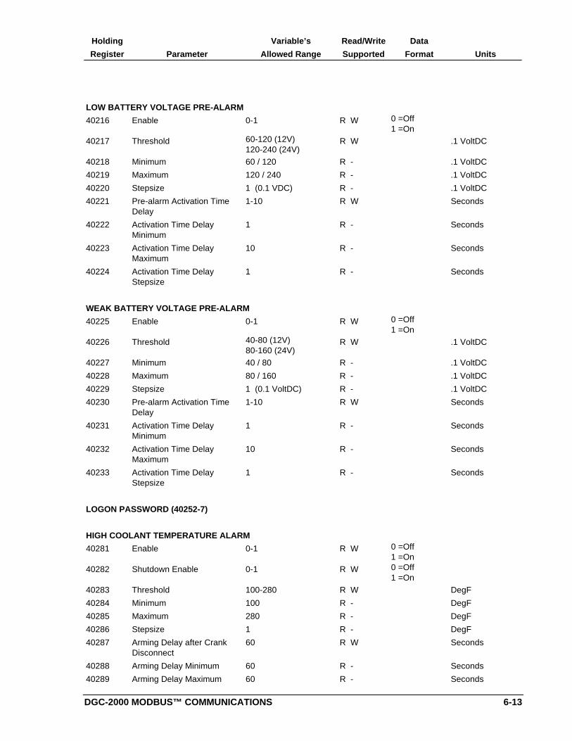
DGC-2000 MODBUS™ COMMUNICATIONS 6-13
Holding Variable’s Read/Write Data
Register Parameter Allowed Range Supported Format Units
LOW BATTERY VOLTAGE PRE-ALARM
40216 Enable 0-1 R W 0 =Off1 =On
40217 Threshold 60-120 (12V)120-240 (24V)
R W .1 VoltDC
40218 Minimum 60 / 120 R - .1 VoltDC
40219 Maximum 120 / 240 R - .1 VoltDC
40220 Stepsize 1 (0.1 VDC) R - .1 VoltDC
40221 Pre-alarm Activation TimeDelay
1-10 R W Seconds
40222 Activation Time DelayMinimum
1 R - Seconds
40223 Activation Time DelayMaximum
10 R - Seconds
40224 Activation Time DelayStepsize
1 R - Seconds
WEAK BATTERY VOLTAGE PRE-ALARM
40225 Enable 0-1 R W 0 =Off1 =On
40226 Threshold 40-80 (12V)80-160 (24V)
R W .1 VoltDC
40227 Minimum 40 / 80 R - .1 VoltDC
40228 Maximum 80 / 160 R - .1 VoltDC
40229 Stepsize 1 (0.1 VoltDC) R - .1 VoltDC
40230 Pre-alarm Activation TimeDelay
1-10 R W Seconds
40231 Activation Time DelayMinimum
1 R - Seconds
40232 Activation Time DelayMaximum
10 R - Seconds
40233 Activation Time DelayStepsize
1 R - Seconds
LOGON PASSWORD (40252-7)
HIGH COOLANT TEMPERATURE ALARM
40281 Enable 0-1 R W 0 =Off1 =On
40282 Shutdown Enable 0-1 R W 0 =Off1 =On
40283 Threshold 100-280 R W DegF
40284 Minimum 100 R - DegF
40285 Maximum 280 R - DegF
40286 Stepsize 1 R - DegF
40287 Arming Delay after CrankDisconnect
60 R W Seconds
40288 Arming Delay Minimum 60 R - Seconds
40289 Arming Delay Maximum 60 R - Seconds

6-14 DGC-2000 MODBUS™ COMMUNICATIONS
Holding Variable’s Read/Write Data
Register Parameter Allowed Range Supported Format Units
40290 Arming Delay Stepsize 0 R - Seconds
LOW OIL PRESSURE ALARM
40291 Enable 0-1 R W 0 =Off1 =On
40292 Shutdown Enable 0-1 R W 0 =Off1 =On
40293 Threshold 3-100 R W PSI
40294 Minimum 3 R - PSI
40295 Maximum 100 R - PSI
40296 Stepsize 1 R - PSI
40297 Arming Delay after CrankDisconnect
5-15 R W Seconds
40298 Arming Delay Minimum 5 R - Seconds
40299 Arming Delay Maximum 15 R - Seconds
40300 Arming Delay Stepsize 1 R - Seconds
OVERSPEED ALARM
40301 Enable 0-1 R W 0 =Off1 =On
40302 Shutdown Enable 0-1 R W 0 =Off1 =On
40303 Threshold 105-140 R W % of Rated
40304 Minimum 105 R - % of Rated
40305 Maximum 140 R - % of Rated
40306 Stepsize 1 R - % of Rated
40307 Alarm Activation Time Delay 0-500 R W MilliSec
40308 Activation Time DelayMinimum
0 R - MilliSec
40309 Activation Time DelayMaximum
500 R - MilliSec
40310 Activation Time DelayStepsize
10 R - MilliSec
SENDER FAIL ALARMS
40311 Coolant Temperature SenderFailure Alarm Enable
0-1 R W 0 =Off1 =On
40312 Oil Pressure Sender FailureAlarm Enable
0-1 R W 0 =Off1 =On
40314 Magnetic Pick-up Failure
Alarm Enable
0-1 R W 0 =Off1 =On
40315 Loss of Generator VoltageAlarm Enable
0-1 R W 0 =Off1 =On
40316 Pre-alarm Buzzer Enable 0-1 R W 0 =Off1 =On
40317 Battery Charger Failure
Pre-alarm Enable
0-1 R W 0 =Off1 =On
40318 Global Sender Failure AlarmTime Delay
1-10 R W Seconds

DGC-2000 MODBUS™ COMMUNICATIONS 6-15
Holding Variable’s Read/Write Data
Register Parameter Allowed Range Supported Format Units
40319 Coolant Temperature SenderFailure Alarm ActivationDelay
5-30 (increment size of5)
R W Minutes
CRANKING PARAMETERS
40351 Cranking Style 0-1 R W 0=Contin.1=Cycle
40352 Number of Crank Cycles 1-7 R W
40353 Number of Crank CyclesMinimum
1 R -
40354 Number of Crank CyclesMaximum
7 R -
40355 Number of Crank CyclesStepsize
1 R -
40356 Cycle Crank Time 5-15 R W Seconds
40357 Cycle Crank Time Minimum 5 R - Seconds
40358 Cycle Crank Time Maximum 15 R - Seconds
40359 Cycle Crank Time Stepsize 1 R - Seconds
40360 Continuous Crank Time 1-60 R W Seconds
40361 Continuous Crank TimeMinimum
1 R - Seconds
40362 Continuous Crank TimeMaximum
60 R - Seconds
40363 Continuous Crank TimeStepsize
1 R - Seconds
40364 Crank Disconnect Limit 10-100 R W % of Rated
40365 Crank Disconnect LimitMinimum
10 R - % of Rated
40366 Crank Disconnect LimitMaximum
100 R - % of Rated
40367 Crank Disconnect LimitStepsize
1 R - % of Rated
40368 Pre-crank Delay 0-30 R W Seconds
40369 Pre-crank Delay Minimum 0 R - Seconds
40370 Pre-crank Delay Maximum 30 R - Seconds
40371 Pre-crank Delay Stepsize 1 R - Seconds
40372 Pre-crank Contact afterDisconnect
0-1 R W 0=Open1=Closed
SYSTEM MONITOR
40374 Remaining Cooldown Time 0-60 R - Minutes
40375 <Reserved>
40376 Active Speed Signal Sources 1-4 R - 1 =MPU2 =ALT3 =GEN4 =NONE
40377 Sender Failure Alarm Codes R - b0=Cool Tempb1=Oil Pressb2 Reservedb3=Spd Signalb4=Gen Voltb5-b7 NotUsed

6-16 DGC-2000 MODBUS™ COMMUNICATIONS
Holding Variable’s Read/Write Data
Register Parameter Allowed Range Supported Format Units
40378 Alarm Codes R - b0=Hi CoolTempb1 LowCoolant Levelb2=Airboxb3=E-Stopb4=SenderFailb5=Over-crankb6=Over-speedb7=Low OilPress
40379 Pre-Alarm Codes R - b0=Hi CoolTempb1=Low CoolTempb2=Weak Battb3=Low Battb4 =Batt ovb5=ChargerFailb6=ServiceDueb7=kWOverload
40380 Pre-Alarm Codes, Group 2 R - b0=Low OilPressb1=Low Fuelb2 Reservedb3 Reservedb4-b7 NotUsed
40381 Engine Coolant Temperature R - DegF
40382 Engine Oil Pressure R - PSI
40383 Battery Voltage R - .1 VoltDC
40384 Fuel Level R - % Full Tank
40385 Time Remaining untilMaintenance
R - Hours
40386 Accumulated EngineRuntime(a)
R - DP Minutes x 10000
40387 Accumulated EngineRuntime(b)
R - DP Minutes
40388 Accumulated EngineRuntime Warranty(a)
R W DP Minutes x 10000
40389 Accumulated EngineRuntime Warranty(b)
R W DP Minutes
40390 Engine Speed(a) R - DP RPM x 10000
40391 Engine Speed(b) R - DP RPM
40392 Engine Load(a) R - DP %
40393 Engine Load(b) R - DP %
GENERATOR MONITOR
40394 Phase a-b RMS Voltage(a) R - DP RMS Volt x10000
40395 Phase a-b RMS Voltage(b) R - DP RMS Volt
40396 Phase b-c RMS Voltage(a) R - DP RMS Volt x10000
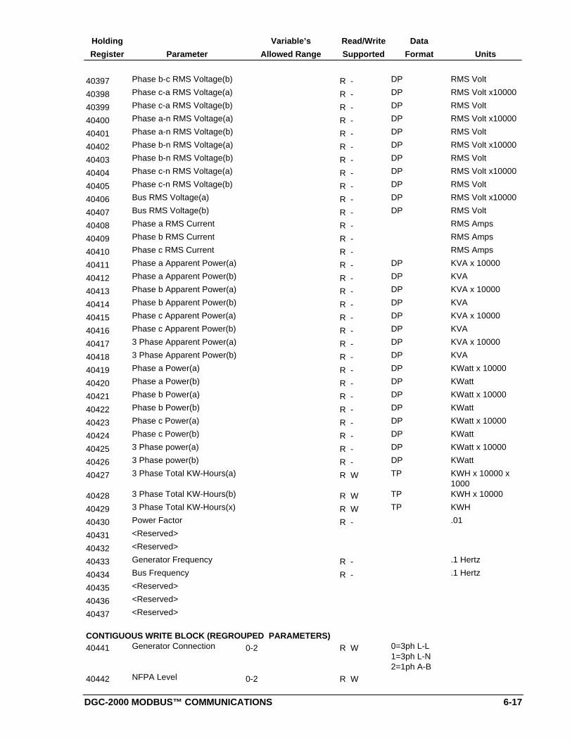
DGC-2000 MODBUS™ COMMUNICATIONS 6-17
Holding Variable’s Read/Write Data
Register Parameter Allowed Range Supported Format Units
40397 Phase b-c RMS Voltage(b) R - DP RMS Volt
40398 Phase c-a RMS Voltage(a) R - DP RMS Volt x10000
40399 Phase c-a RMS Voltage(b) R - DP RMS Volt
40400 Phase a-n RMS Voltage(a) R - DP RMS Volt x10000
40401 Phase a-n RMS Voltage(b) R - DP RMS Volt
40402 Phase b-n RMS Voltage(a) R - DP RMS Volt x10000
40403 Phase b-n RMS Voltage(b) R - DP RMS Volt
40404 Phase c-n RMS Voltage(a) R - DP RMS Volt x10000
40405 Phase c-n RMS Voltage(b) R - DP RMS Volt
40406 Bus RMS Voltage(a) R - DP RMS Volt x10000
40407 Bus RMS Voltage(b) R - DP RMS Volt
40408 Phase a RMS Current R - RMS Amps
40409 Phase b RMS Current R - RMS Amps
40410 Phase c RMS Current R - RMS Amps
40411 Phase a Apparent Power(a) R - DP KVA x 10000
40412 Phase a Apparent Power(b) R - DP KVA
40413 Phase b Apparent Power(a) R - DP KVA x 10000
40414 Phase b Apparent Power(b) R - DP KVA
40415 Phase c Apparent Power(a) R - DP KVA x 10000
40416 Phase c Apparent Power(b) R - DP KVA
40417 3 Phase Apparent Power(a) R - DP KVA x 10000
40418 3 Phase Apparent Power(b) R - DP KVA
40419 Phase a Power(a) R - DP KWatt x 10000
40420 Phase a Power(b) R - DP KWatt
40421 Phase b Power(a) R - DP KWatt x 10000
40422 Phase b Power(b) R - DP KWatt
40423 Phase c Power(a) R - DP KWatt x 10000
40424 Phase c Power(b) R - DP KWatt
40425 3 Phase power(a) R - DP KWatt x 10000
40426 3 Phase power(b) R - DP KWatt
40427 3 Phase Total KW-Hours(a) R W TP KWH x 10000 x1000
40428 3 Phase Total KW-Hours(b) R W TP KWH x 10000
40429 3 Phase Total KW-Hours(x) R W TP KWH
40430 Power Factor R - .01
40431 <Reserved>
40432 <Reserved>
40433 Generator Frequency R - .1 Hertz
40434 Bus Frequency R - .1 Hertz
40435 <Reserved>
40436 <Reserved>
40437 <Reserved>
CONTIGUOUS WRITE BLOCK (REGROUPED PARAMETERS)40441 Generator Connection 0-2 R W 0=3ph L-L
1=3ph L-N2=1ph A-B
40442 NFPA Level 0-2 R W
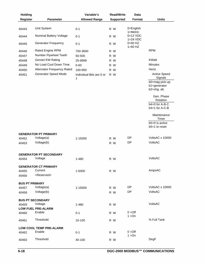
6-18 DGC-2000 MODBUS™ COMMUNICATIONS
Holding Variable’s Read/Write Data
Register Parameter Allowed Range Supported Format Units
40443 Unit System 0-1 R W 0=English1=Metric
40444 Nominal Battery Voltage 0-1 R W 0=12 VDC1=24 VDC
40445 Generator Frequency 0-1 R W 0=50 HZ1=60 HZ
40446 Rated Engine RPM 750-3600 R W RPM
40447 Number Flywheel Teeth 50-500 R W
40448 Genset KW Rating 25-9999 R W KWatt
40449 No Load Cool Down Time 0-60 R W Minutes
40450 Alternator Frequency Rated 100-900 R W Hertz
40451 Generator Speed Mode Individual Bits are 0 or1
R W Active SpeedSignals
b0=mag pick-upb1=generatorb2=chg. alt.
Gen. PhaseRotation
b4=0 for A-B-Cb4=1 for A-C-B
MaintenanceTimer
b5=0 is activeb5=1 to reset
GENERATOR PT PRIMARY40452 Voltage(a) 1-15000 R W DP VoltsAC x 10000
40453 Voltage(b) R W DP VoltsAC
GENERATOR PT SECONDARY40454 Voltage 1-480 R W VoltsAC
GENERATOR CT PRIMARY40455 Current 1-5000 R W AmpsAC
40456 <Reserved>
BUS PT PRIMARY40457 Voltage(a) 1-15000 R W DP VoltsAC x 10000
40458 Voltage(b) R W DP VoltsAC
BUS PT SECONDARY40459 Voltage 1-480 R W VoltsAC
LOW FUEL PRE-ALARM40460 Enable 0-1 R W 0 =Off
1 =On
40461 Threshold 10-100 R W % Full Tank
LOW COOL TEMP PRE-ALARM40462 Enable 0-1 R W 0 =Off
1 =On
40463 Threshold 40-100 R W DegF

DGC-2000 MODBUS™ COMMUNICATIONS 6-19
Holding Variable’s Read/Write Data
Register Parameter Allowed Range Supported Format Units
BATTERY OVERVOLTAGE PRE-ALARM40464 Enable 0-1 R W 0 =Off
1 =On
40465 Threshold 140-160 (12V)
240-320 (24V)
R W .1 VoltDC
MAINTENANCE INTERVAL PRE-ALARM40466 Enable 0-1 R W 0 =Off
1 =On
40467 Threshold 0-5000 R W Hours
ENGINE KW OVERLOAD PRE-ALARM40468 Enable 0-1 R W 0 =Off
1 =On
40469 Threshold 95-140 R W % of Rated
HIGH COOLANT TEMPERATURE PRE-ALARM40470 Enable 0-1 R W 0 =Off
1 =On
40471 Threshold 100-280 R W DegF
LOW OIL PRESSURE PRE-ALARM40472 Enable 0-1 R W 0 =Off
1 =On
40473 Threshold 3-100 R W PSI
LOW BATTERY VOLTAGE PRE-ALARM40474 Enable 0-1 R W 0 =Off
1 =On
40475 Threshold 60-120 (12V)
120-240 (24V)
R W .1 VoltDC
40476 Pre-alarm Activation TimeDelay
1-10 R W Seconds
WEAK BATTERY VOLTAGE PRE-ALARM40477 Enable 0-1 R W 0 =Off
1 =On
40478 Threshold 40-80 (12V)80-160 (24V)
R W .1 VoltDC
40479 Pre-alarm Activation TimeDelay
1-10 R W Seconds
HIGH COOLANT TEMPERATURE ALARM40480 Enable 0-1 R W 0 =Off
1 =On
40481 Shutdown Enable 0-1 R W 0 =Off1 =On
40482 Threshold 100-280 R W DegF
40483 Arming Delay after CrankDisconnect
60 R W Seconds
LOW OIL PRESSURE ALARM40484 Enable 0-1 R W 0 =Off
1 =On
40485 Shutdown Enable 0-1 R W 0 =Off1 =On
40486 Threshold 3-100 R W PSI

6-20 DGC-2000 MODBUS™ COMMUNICATIONS
Holding Variable’s Read/Write Data
Register Parameter Allowed Range Supported Format Units
40487 Arming Delay after CrankDisconnect
5-15 R W Seconds
OVERSPEED ALARM40488 Enable 0-1 R W 0 =Off
1 =On
40489 Shutdown Enable 0-1 R W 0 =Off1 =On
40490 Threshold 105-140 R W % of Rated
40491 Alarm Activation Time Delay 0-500 R W MilliSec
SENDER FAIL ALARMS40492 Coolant Temperature Sender
Failure Alarm Enable0-1 R W 0 =Off
1 =On
40493 Oil Pressure Sender FailureAlarm Enable
0-1 R W 0 =Off1 =On
40495 Magnetic Pick-up FailureAlarm Enable
0-1 R W 0 =Off1 =On
40496 Loss of Generator VoltageAlarm Enable
0-1 R W 0 =Off1 =On
40497 Pre-alarm Buzzer Enable 0-1 R W 0 =Off1 =On
40498 Battery Charger FailurePre-alarm Enable
0-1 R W 0 =Off1 =On
40499 Global Sender Failure AlarmTime Delay
0-10 R W Seconds
CRANKING PARAMETERS40500 Cranking Style 0-1 R W 0=Contin.
1=Cycle
40501 Number of Crank Cycles 1-7 R W
40502 Cycle Crank Time 5-15 R W Seconds
40503 Continuous Crank Time 1-60 R W Seconds
40504 Crank Disconnect Limit 10-100 R W % of Rated
40505 Pre-crank Delay 0-30 R W Seconds
40506 Pre-crank Contact afterDisconnect
0-1 R W 0=Open1=Closed
SYSTEM MONITOR40507 Accumulated Engine
Runtime Warranty(a)R W DP Minutes x 10000
40508 Accumulated EngineRuntime Warranty(b)
R W DP Minutes
CALIBRATION40509 Voltage Calibration A(a) R W DP x 10000
40510 Voltage Calibration A(b) R W DP x 1
40511 Voltage Calibration B(a) R W DP x 10000
40512 Voltage Calibration B(b) R W DP x 1
40513 Voltage Calibration C(a) R W DP x 10000
40514 Voltage Calibration C(b) R W DP x 1
40515 Voltage Calibration N(a) R W DP x 10000
40516 Voltage Calibration N(b) R W DP x 1
40517 Current Calibration A(a) R W DP x 10000
40518 Current Calibration A(b) R W DP x 1
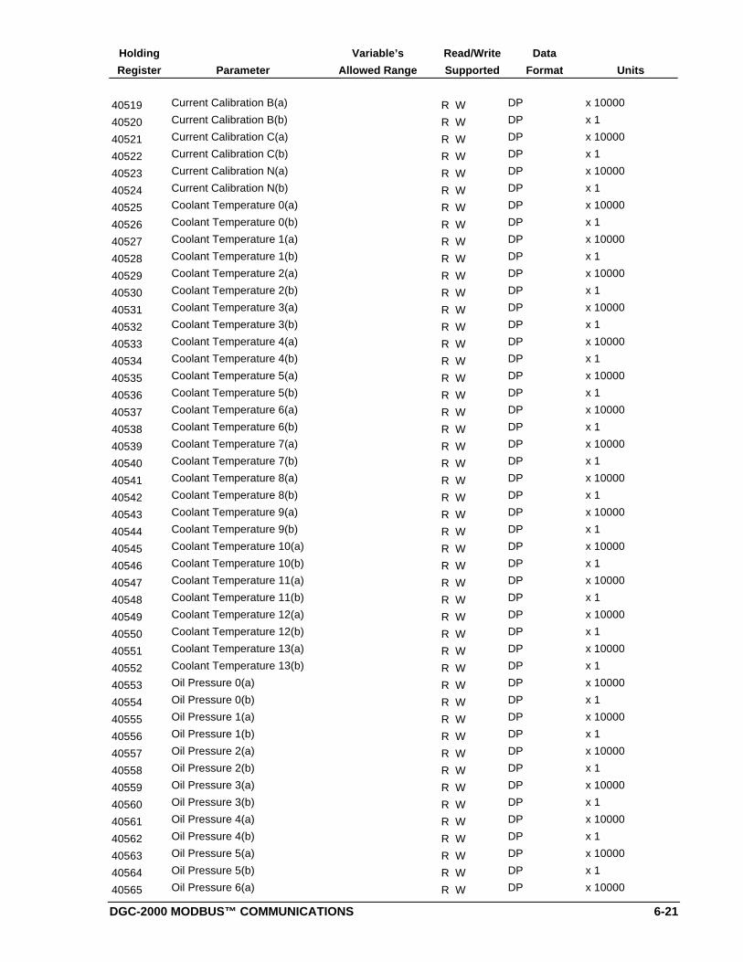
DGC-2000 MODBUS™ COMMUNICATIONS 6-21
Holding Variable’s Read/Write Data
Register Parameter Allowed Range Supported Format Units
40519 Current Calibration B(a) R W DP x 10000
40520 Current Calibration B(b) R W DP x 1
40521 Current Calibration C(a) R W DP x 10000
40522 Current Calibration C(b) R W DP x 1
40523 Current Calibration N(a) R W DP x 10000
40524 Current Calibration N(b) R W DP x 1
40525 Coolant Temperature 0(a) R W DP x 10000
40526 Coolant Temperature 0(b) R W DP x 1
40527 Coolant Temperature 1(a) R W DP x 10000
40528 Coolant Temperature 1(b) R W DP x 1
40529 Coolant Temperature 2(a) R W DP x 10000
40530 Coolant Temperature 2(b) R W DP x 1
40531 Coolant Temperature 3(a) R W DP x 10000
40532 Coolant Temperature 3(b) R W DP x 1
40533 Coolant Temperature 4(a) R W DP x 10000
40534 Coolant Temperature 4(b) R W DP x 1
40535 Coolant Temperature 5(a) R W DP x 10000
40536 Coolant Temperature 5(b) R W DP x 1
40537 Coolant Temperature 6(a) R W DP x 10000
40538 Coolant Temperature 6(b) R W DP x 1
40539 Coolant Temperature 7(a) R W DP x 10000
40540 Coolant Temperature 7(b) R W DP x 1
40541 Coolant Temperature 8(a) R W DP x 10000
40542 Coolant Temperature 8(b) R W DP x 1
40543 Coolant Temperature 9(a) R W DP x 10000
40544 Coolant Temperature 9(b) R W DP x 1
40545 Coolant Temperature 10(a) R W DP x 10000
40546 Coolant Temperature 10(b) R W DP x 1
40547 Coolant Temperature 11(a) R W DP x 10000
40548 Coolant Temperature 11(b) R W DP x 1
40549 Coolant Temperature 12(a) R W DP x 10000
40550 Coolant Temperature 12(b) R W DP x 1
40551 Coolant Temperature 13(a) R W DP x 10000
40552 Coolant Temperature 13(b) R W DP x 1
40553 Oil Pressure 0(a) R W DP x 10000
40554 Oil Pressure 0(b) R W DP x 1
40555 Oil Pressure 1(a) R W DP x 10000
40556 Oil Pressure 1(b) R W DP x 1
40557 Oil Pressure 2(a) R W DP x 10000
40558 Oil Pressure 2(b) R W DP x 1
40559 Oil Pressure 3(a) R W DP x 10000
40560 Oil Pressure 3(b) R W DP x 1
40561 Oil Pressure 4(a) R W DP x 10000
40562 Oil Pressure 4(b) R W DP x 1
40563 Oil Pressure 5(a) R W DP x 10000
40564 Oil Pressure 5(b) R W DP x 1
40565 Oil Pressure 6(a) R W DP x 10000

6-22 DGC-2000 MODBUS™ COMMUNICATIONS
Holding Variable’s Read/Write Data
Register Parameter Allowed Range Supported Format Units
40566 Oil Pressure 6(b) R W DP x 1
40567 Oil Pressure 7(a) R W DP x 10000
40568 Oil Pressure 7(b) R W DP x 1
40569 Oil Pressure 8(a) R W DP x 10000
40570 Oil Pressure 8(b) R W DP x 1
40571 Oil Pressure 9(a) R W DP x 10000
40572 Oil Pressure 9(b) R W DP x 1
40573 Oil Pressure 10(a) R W DP x 10000
40574 Oil Pressure 10(b) R W DP x 1
40575 Oil Pressure 11(a) R W DP x 10000
40576 Oil Pressure 11(b) R W DP x 1
40577 Oil Pressure 12(a) R W DP x 10000
40578 Oil Pressure 12(b) R W DP x 1
40579 Oil Pressure 13(a) R W DP x 10000
40580 Oil Pressure 13(b) R W DP x 1
SYSTEM MONITOR - Continuation40581 System Configuration 32, 64, 128 R W 32=AUTO
64=OFF128=RUN
40582 System State 0-5 R - 0=RESET1=READY2=CRANK3=REST4=RUN5=ALARM
CALIBRATION - Continuation40583 Phase angle (a) R W DP
40584 Phase angle (b) R W DP
GENERATOR MONITOR - Continuation40585 Power Factor State 0-3 R 0=+LAG
1=-LEAD2=-LAG3=+LEAD
DGC-2000 WINDOWS® SOFTWARE 7-1
SECTION 7 • DGC-2000 WINDOWS® SOFTWARE
GENERAL
DGC-2000 Windows® Software is an application that enhances communication between the personalcomputer (PC) user and the DGC-2000. DGC-2000 Windows® Software serves two main purposes. First,it provides a user friendly environment for changing DGC-2000 settings. Second, it provides on-screen,real time metering that is updated approximately every one and one-half seconds. The interface softwarealso allows users to save the current setting configurations and data information to a disk. Users cansave multiple setups for later use which saves setup time when configuring multiple units. Without DGC-2000 Windows® Software, users must be familiar with the limited function operations at the DGC-2000front panel.
INSTALLATION
DGC 2000 Windows software contains a setup utility that installs the program on your PC. When it installsthe program, an uninstall icon is created that you may use to uninstall (remove) the program from yourPC. The minimum operating requirements are listed in the following paragraph.
Operating Requirements
To use DGC 2000 Windows software, you will need the following:
• IBM compatible PC, 486DX2 or faster, and a minimum of four megabytes of RAM• Microsoft Windows 95 or Windows 3.1• 3.5 inch floppy drive• RS-232 Serial port
Installing The Program On Your PC With Windows® 95
1. Insert disk 1 in the 3.5 inch floppy drive
2. From the Task Bar select Start then Run
3. Enter a:\Setup.exe and press enter or click on Browse and select the A: drive and double clickSetup.exe.
Installing The Program On Your PC With Windows® 3.1
1. Insert disk 1 in the 3.5 inch floppy drive
2. From Program Manager select File menu and then Run
3. Enter a:\Setup.exe and press enter or select the A: drive and double click Setup.exe.
Configuring The System
Communication with a DGC 2000 unit can be done by a direct cable connection or through a modem. Theinstallation section of the manual has the RS-232 serial link connection pinouts. For direct connection usea standard RS-232 cable. For modem communications connection use a modem to the DGC RS-232 portand a null-modem cable. Connect another modem to the host computer with a standard RS-232 cable.
INITIALIZING COMMUNICATIONS WITH THE DGC 2000 Windows Software
Select the DGC 2000 icon from Program Manger or select DGC 2000 under the Basler Electric directoryunder Programs in the Start Menu. A momentary dialog box (splash screen) opens that displays theBasler Electric Logo, program name, and revision identification. After the splash screen the initial screen(Figure 7-1) will follow. Pull down the Communications menu select Open and then either RS232 or
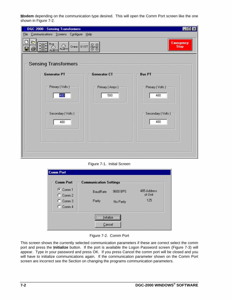
7-2 DGC-2000 WINDOWS® SOFTWARE
Modem depending on the communication type desired. This will open the Comm Port screen like the oneshown in Figure 7-2.
Figure 7-1. Initial Screen
Figure 7-2. Comm Port
This screen shows the currently selected communication parameters if these are correct select the commport and press the Initialize button. If the port is available the Logon Password screen (Figure 7-3) willappear. Type in your password and press OK. If you press Cancel the comm port will be closed and youwill have to initialize communications again. If the communication parameter shown on the Comm Portscreen are incorrect see the Section on changing the programs communication parameters.
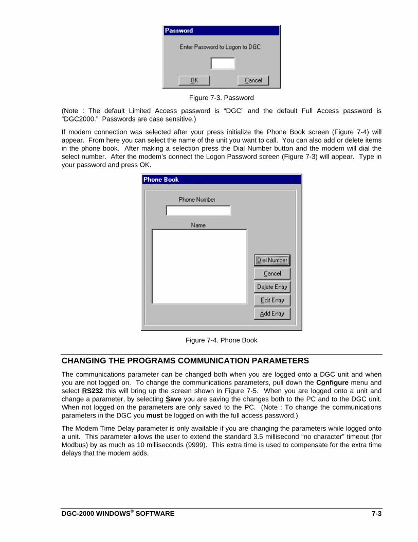
DGC-2000 WINDOWS® SOFTWARE 7-3
Figure 7-3. Password
(Note : The default Limited Access password is “DGC” and the default Full Access password is“DGC2000.” Passwords are case sensitive.)
If modem connection was selected after your press initialize the Phone Book screen (Figure 7-4) willappear. From here you can select the name of the unit you want to call. You can also add or delete itemsin the phone book. After making a selection press the Dial Number button and the modem will dial theselect number. After the modem’s connect the Logon Password screen (Figure 7-3) will appear. Type inyour password and press OK.
Figure 7-4. Phone Book
CHANGING THE PROGRAMS COMMUNICATION PARAMETERS
The communications parameter can be changed both when you are logged onto a DGC unit and whenyou are not logged on. To change the communications parameters, pull down the Configure menu andselect RS232 this will bring up the screen shown in Figure 7-5. When you are logged onto a unit andchange a parameter, by selecting Save you are saving the changes both to the PC and to the DGC unit.When not logged on the parameters are only saved to the PC. (Note : To change the communicationsparameters in the DGC you must be logged on with the full access password.)
The Modem Time Delay parameter is only available if you are changing the parameters while logged ontoa unit. This parameter allows the user to extend the standard 3.5 millisecond “no character” timeout (forModbus) by as much as 10 milliseconds (9999). This extra time is used to compensate for the extra timedelays that the modem adds.
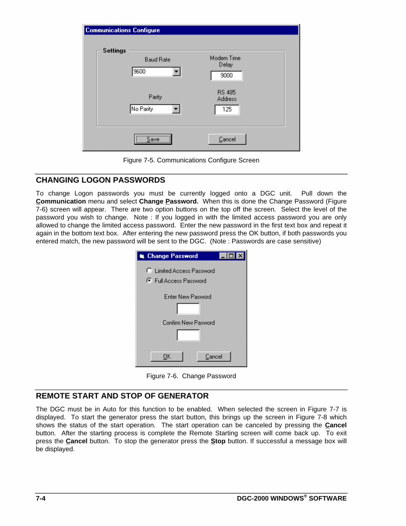
7-4 DGC-2000 WINDOWS® SOFTWARE
Figure 7-5. Communications Configure Screen
CHANGING LOGON PASSWORDS
To change Logon passwords you must be currently logged onto a DGC unit. Pull down theCommunication menu and select Change Password. When this is done the Change Password (Figure7-6) screen will appear. There are two option buttons on the top off the screen. Select the level of thepassword you wish to change. Note : If you logged in with the limited access password you are onlyallowed to change the limited access password. Enter the new password in the first text box and repeat itagain in the bottom text box. After entering the new password press the OK button, if both passwords youentered match, the new password will be sent to the DGC. (Note : Passwords are case sensitive)
Figure 7-6. Change Password
REMOTE START AND STOP OF GENERATOR
The DGC must be in Auto for this function to be enabled. When selected the screen in Figure 7-7 isdisplayed. To start the generator press the start button, this brings up the screen in Figure 7-8 whichshows the status of the start operation. The start operation can be canceled by pressing the Cancelbutton. After the starting process is complete the Remote Starting screen will come back up. To exitpress the Cancel button. To stop the generator press the Stop button. If successful a message box willbe displayed.

DGC-2000 WINDOWS® SOFTWARE 7-5
Figure 7-7. Remote Starting
Figure 7-8. Starting Status
CHANGING SETTINGS
Settings are arranged in five groups.
• Sensing Transformers• Pre-Alarms• Alarm• Crank• System
To change settings, you must first select the screen associated with the setting. When you are logged onwith the limited access password you can see all of the current settings in the unit but cannot change all ofthem. The settings that can not be changed will be disabled so that you can not select them. Doubleclicking on any white rectangular box will allow you to change (if allowed) that setting. Once all of thesettings have been entered, pull down the Communications menu and select Send to DGC, this willsend the settings to the DGC and verify them.
MENUS
File Menu
1) Open - Opens a saved settings file from a disk.
2) Save - Saves the current settings to a file on a disk. The file will be saved with the extension .dgc.
3) Print - Used to print a hard copy of the settings file.
4) Exit - Used to exit the program.
Communications Menu
1) Open - Used to initiate communications with the DGC2000.
2) Close - Used to terminate communications with the DGC2000.
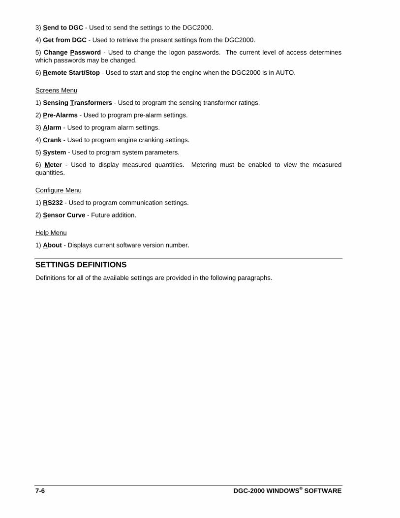
7-6 DGC-2000 WINDOWS® SOFTWARE
3) Send to DGC - Used to send the settings to the DGC2000.
4) Get from DGC - Used to retrieve the present settings from the DGC2000.
5) Change Password - Used to change the logon passwords. The current level of access determineswhich passwords may be changed.
6) Remote Start/Stop - Used to start and stop the engine when the DGC2000 is in AUTO.
Screens Menu
1) Sensing Transformers - Used to program the sensing transformer ratings.
2) Pre-Alarms - Used to program pre-alarm settings.
3) Alarm - Used to program alarm settings.
4) Crank - Used to program engine cranking settings.
5) System - Used to program system parameters.
6) Meter - Used to display measured quantities. Metering must be enabled to view the measuredquantities.
Configure Menu
1) RS232 - Used to program communication settings.
2) Sensor Curve - Future addition.
Help Menu
1) About - Displays current software version number.
SETTINGS DEFINITIONS
Definitions for all of the available settings are provided in the following paragraphs.
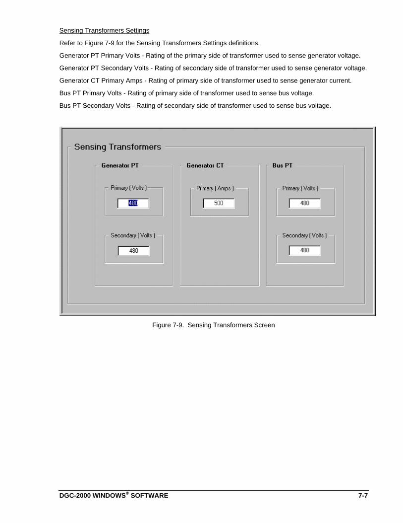
DGC-2000 WINDOWS® SOFTWARE 7-7
Sensing Transformers Settings
Refer to Figure 7-9 for the Sensing Transformers Settings definitions.
Generator PT Primary Volts - Rating of the primary side of transformer used to sense generator voltage.
Generator PT Secondary Volts - Rating of secondary side of transformer used to sense generator voltage.
Generator CT Primary Amps - Rating of primary side of transformer used to sense generator current.
Bus PT Primary Volts - Rating of primary side of transformer used to sense bus voltage.
Bus PT Secondary Volts - Rating of secondary side of transformer used to sense bus voltage.
Figure 7-9. Sensing Transformers Screen
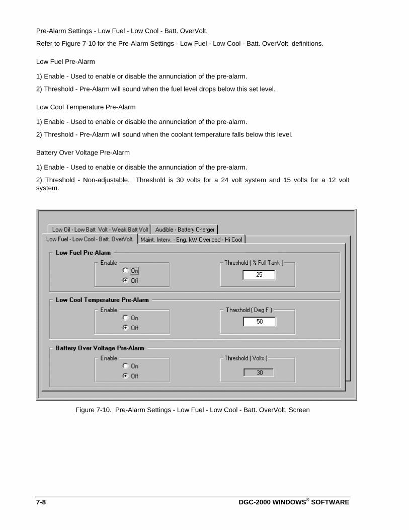
7-8 DGC-2000 WINDOWS® SOFTWARE
Pre-Alarm Settings - Low Fuel - Low Cool - Batt. OverVolt.
Refer to Figure 7-10 for the Pre-Alarm Settings - Low Fuel - Low Cool - Batt. OverVolt. definitions.
Low Fuel Pre-Alarm
1) Enable - Used to enable or disable the annunciation of the pre-alarm.
2) Threshold - Pre-Alarm will sound when the fuel level drops below this set level.
Low Cool Temperature Pre-Alarm
1) Enable - Used to enable or disable the annunciation of the pre-alarm.
2) Threshold - Pre-Alarm will sound when the coolant temperature falls below this level.
Battery Over Voltage Pre-Alarm
1) Enable - Used to enable or disable the annunciation of the pre-alarm.
2) Threshold - Non-adjustable. Threshold is 30 volts for a 24 volt system and 15 volts for a 12 voltsystem.
Figure 7-10. Pre-Alarm Settings - Low Fuel - Low Cool - Batt. OverVolt. Screen
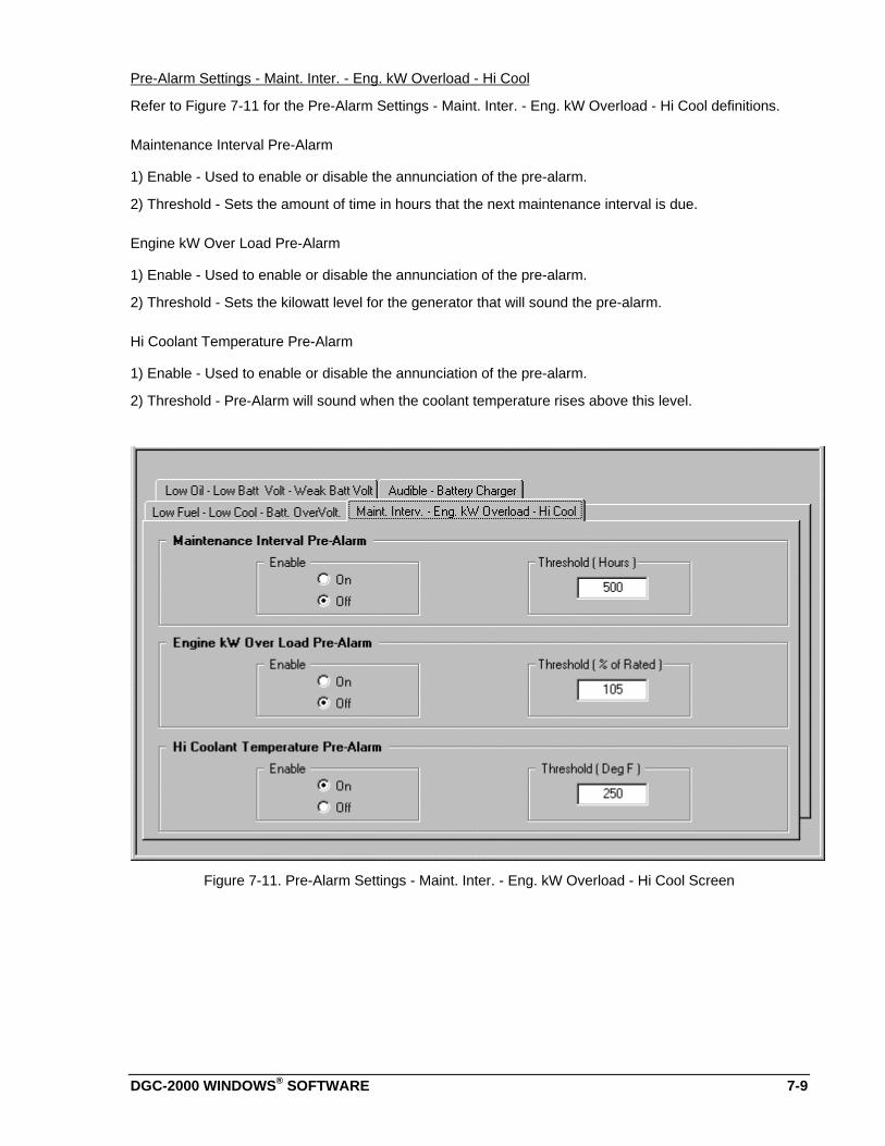
DGC-2000 WINDOWS® SOFTWARE 7-9
Pre-Alarm Settings - Maint. Inter. - Eng. kW Overload - Hi Cool
Refer to Figure 7-11 for the Pre-Alarm Settings - Maint. Inter. - Eng. kW Overload - Hi Cool definitions.
Maintenance Interval Pre-Alarm
1) Enable - Used to enable or disable the annunciation of the pre-alarm.
2) Threshold - Sets the amount of time in hours that the next maintenance interval is due.
Engine kW Over Load Pre-Alarm
1) Enable - Used to enable or disable the annunciation of the pre-alarm.
2) Threshold - Sets the kilowatt level for the generator that will sound the pre-alarm.
Hi Coolant Temperature Pre-Alarm
1) Enable - Used to enable or disable the annunciation of the pre-alarm.
2) Threshold - Pre-Alarm will sound when the coolant temperature rises above this level.
Figure 7-11. Pre-Alarm Settings - Maint. Inter. - Eng. kW Overload - Hi Cool Screen

7-10 DGC-2000 WINDOWS® SOFTWARE
Pre-Alarm Settings - Low Oil - Low Batt Volt - Weak Batt Volt
Refer to Figure 7-12 for the Pre-Alarm Settings - Low Oil - Low Batt Volt - Weak Batt Volt definitions
Low Oil Pressure Pre-Alarm
1) Enable - Used to enable or disable the annunciation of the pre-alarm.
2) Threshold - Pre-Alarm will sound when the Oil Pressure falls below this level.
Low Battery Voltage Pre-Alarm
1) Enable - Used to enable or disable the annunciation of the pre-alarm.
2) Threshold - Pre-Alarm will sound when the Battery Voltage falls below this level.
Weak Battery Voltage Pre-Alarm
1) Enable - Used to enable or disable the annunciation of the pre-alarm.
2) Threshold - Pre-Alarm will sound when the Battery Voltage falls below this level during cranking. This isa latching type Pre-Alarm and must be reset from the front panel.
Figure 7-12. Pre-Alarm Settings - Low Oil - Low Batt Volt - Weak Batt Volt Screen
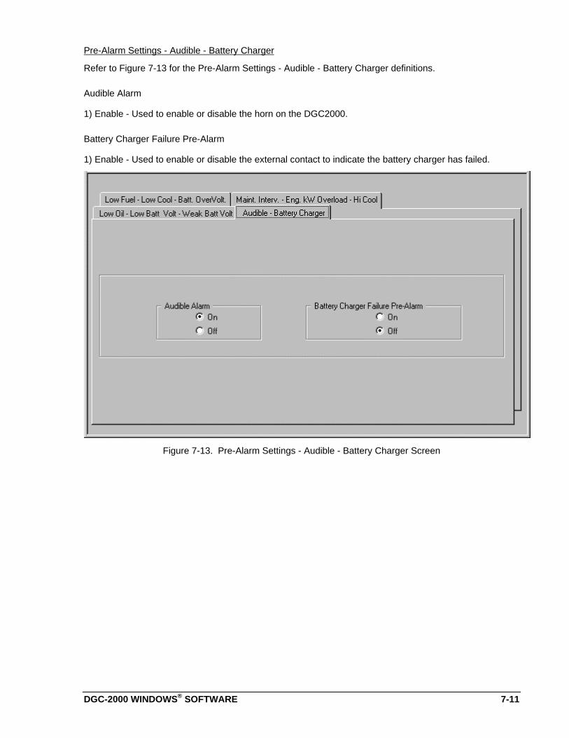
DGC-2000 WINDOWS® SOFTWARE 7-11
Pre-Alarm Settings - Audible - Battery Charger
Refer to Figure 7-13 for the Pre-Alarm Settings - Audible - Battery Charger definitions.
Audible Alarm
1) Enable - Used to enable or disable the horn on the DGC2000.
Battery Charger Failure Pre-Alarm
1) Enable - Used to enable or disable the external contact to indicate the battery charger has failed.
Figure 7-13. Pre-Alarm Settings - Audible - Battery Charger Screen

7-12 DGC-2000 WINDOWS® SOFTWARE
Alarm Settings - Hi Cool Temp - Low Oil Press
Refer to Figure 7-14 for the Alarm Settings - Hi Cool Temp - Low Oil Press definitions.
Hi Cool Temperature Alarm
1) Enable - Used to enable or disable the annunciation of the alarm.
2) Threshold - Sets the threshold level for the coolant temperature.
3) Arming Delay - Unadjustable - After the coolant temperature is above the threshold for 60 Sec theengine will be shutdown.
Low Oil Pressure Alarm
1) Enable - Used to enable or disable the annunciation of the alarm.
2) Threshold - Sets the threshold level for low oil pressure before engine shutdown occurs.
3) Arming Delay - Sets the amount of time delay, after crank disconnect, before the Oil Pressure Alarmbecomes active.
Figure 7-14. Alarm Settings - Hi Cool Temp - Low Oil Press Screen
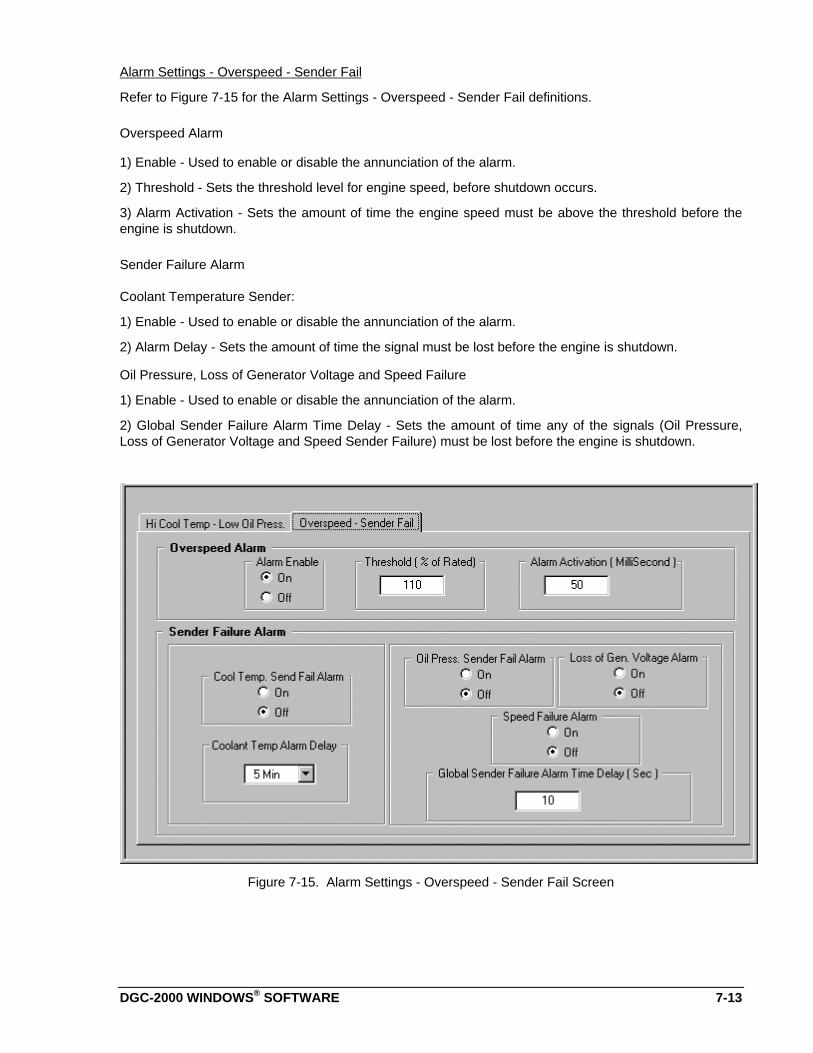
DGC-2000 WINDOWS® SOFTWARE 7-13
Alarm Settings - Overspeed - Sender Fail
Refer to Figure 7-15 for the Alarm Settings - Overspeed - Sender Fail definitions.
Overspeed Alarm
1) Enable - Used to enable or disable the annunciation of the alarm.
2) Threshold - Sets the threshold level for engine speed, before shutdown occurs.
3) Alarm Activation - Sets the amount of time the engine speed must be above the threshold before theengine is shutdown.
Sender Failure Alarm
Coolant Temperature Sender:
1) Enable - Used to enable or disable the annunciation of the alarm.
2) Alarm Delay - Sets the amount of time the signal must be lost before the engine is shutdown.
Oil Pressure, Loss of Generator Voltage and Speed Failure
1) Enable - Used to enable or disable the annunciation of the alarm.
2) Global Sender Failure Alarm Time Delay - Sets the amount of time any of the signals (Oil Pressure,Loss of Generator Voltage and Speed Sender Failure) must be lost before the engine is shutdown.
Figure 7-15. Alarm Settings - Overspeed - Sender Fail Screen
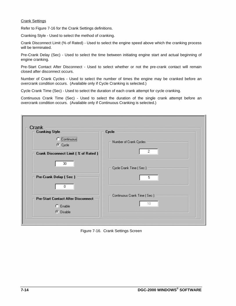
7-14 DGC-2000 WINDOWS® SOFTWARE
Crank Settings
Refer to Figure 7-16 for the Crank Settings definitions.
Cranking Style - Used to select the method of cranking.
Crank Disconnect Limit (% of Rated) - Used to select the engine speed above which the cranking processwill be terminated.
Pre-Crank Delay (Sec) - Used to select the time between initiating engine start and actual beginning ofengine cranking.
Pre-Start Contact After Disconnect - Used to select whether or not the pre-crank contact will remainclosed after disconnect occurs.
Number of Crank Cycles - Used to select the number of times the engine may be cranked before anovercrank condition occurs. (Available only if Cycle Cranking is selected.)
Cycle Crank Time (Sec) - Used to select the duration of each crank attempt for cycle cranking.
Continuous Crank Time (Sec) - Used to select the duration of the single crank attempt before anovercrank condition occurs. (Available only if Continuous Cranking is selected.)
Figure 7-16. Crank Settings Screen
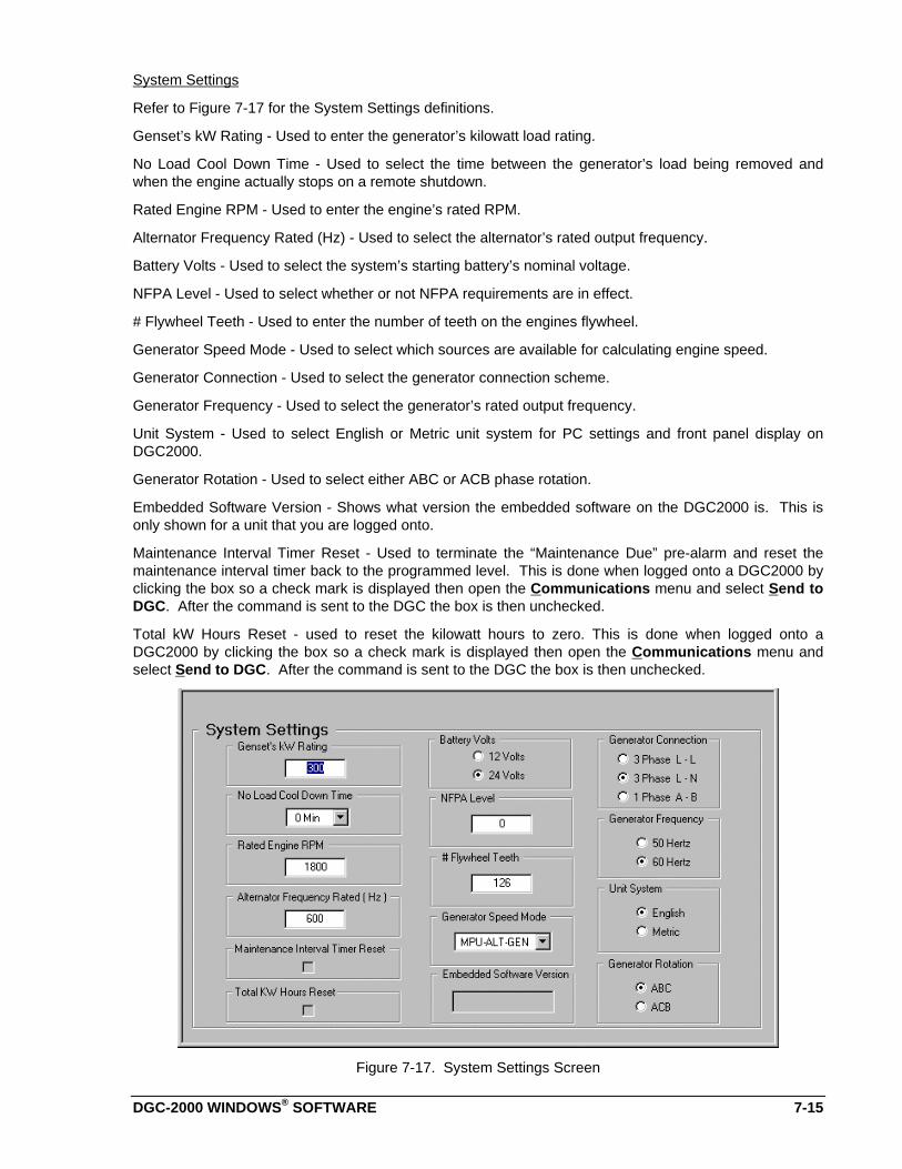
DGC-2000 WINDOWS® SOFTWARE 7-15
System Settings
Refer to Figure 7-17 for the System Settings definitions.
Genset’s kW Rating - Used to enter the generator’s kilowatt load rating.
No Load Cool Down Time - Used to select the time between the generator’s load being removed andwhen the engine actually stops on a remote shutdown.
Rated Engine RPM - Used to enter the engine’s rated RPM.
Alternator Frequency Rated (Hz) - Used to select the alternator’s rated output frequency.
Battery Volts - Used to select the system’s starting battery’s nominal voltage.
NFPA Level - Used to select whether or not NFPA requirements are in effect.
# Flywheel Teeth - Used to enter the number of teeth on the engines flywheel.
Generator Speed Mode - Used to select which sources are available for calculating engine speed.
Generator Connection - Used to select the generator connection scheme.
Generator Frequency - Used to select the generator’s rated output frequency.
Unit System - Used to select English or Metric unit system for PC settings and front panel display onDGC2000.
Generator Rotation - Used to select either ABC or ACB phase rotation.
Embedded Software Version - Shows what version the embedded software on the DGC2000 is. This isonly shown for a unit that you are logged onto.
Maintenance Interval Timer Reset - Used to terminate the “Maintenance Due” pre-alarm and reset themaintenance interval timer back to the programmed level. This is done when logged onto a DGC2000 byclicking the box so a check mark is displayed then open the Communications menu and select Send toDGC. After the command is sent to the DGC the box is then unchecked.
Total kW Hours Reset - used to reset the kilowatt hours to zero. This is done when logged onto aDGC2000 by clicking the box so a check mark is displayed then open the Communications menu andselect Send to DGC. After the command is sent to the DGC the box is then unchecked.
Figure 7-17. System Settings Screen

7-16 DGC-2000 WINDOWS® SOFTWARE
Metering
DGC 2000 Windows software provides a means to monitor the metering data and alarm status. Themetering data and the alarm status are refreshed approximately every 1.5 seconds.
Metering. The metering is separated into six different screens. There is one screen Summary that showsall the available metering values from the DGC 2000 (Refer to Figure 7-18). The other five screens havea detailed subset of these metering values available. To enable metering you must be logged onto a unitand then open the Metering menu and select enable metering. If you are not on the metering screen theprogram will change to the metering screen and start updating the values. When metering is disabled allof the metering screens will be grayed out showing they are inactive.
Figure 7-18. Metering Screen
Alarms. The pre-alarms and alarms are all shown on one screen (refer to Figure 7-19). When a pre-alarm becomes active the LED next to the name of the pre-alarm will be green. A description of the alarmwill be shown on top of the screen and the computer speaker will begin to beep. The label on top of thescreen will contain the same alarm until it goes away and then it will show the next pre-alarm going downthe list that is active. When an alarm becomes active the LED next to the name of the alarm will be red.The screen will jump to the alarm tab and the computer speaker will begin to beep. If the alarm type is aSender Failure the type of sender that failed will be indicated in the Sender Failure type area.
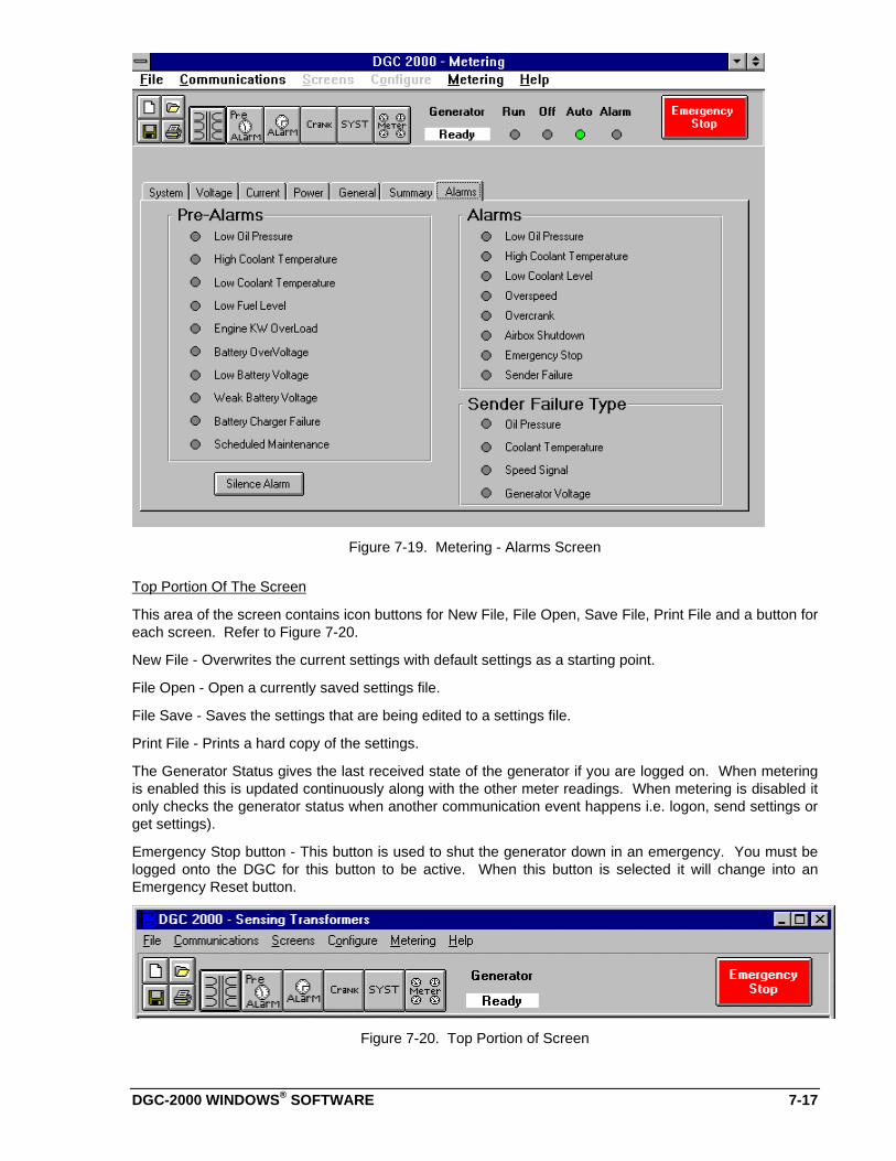
DGC-2000 WINDOWS® SOFTWARE 7-17
Figure 7-19. Metering - Alarms Screen
Top Portion Of The Screen
This area of the screen contains icon buttons for New File, File Open, Save File, Print File and a button foreach screen. Refer to Figure 7-20.
New File - Overwrites the current settings with default settings as a starting point.
File Open - Open a currently saved settings file.
File Save - Saves the settings that are being edited to a settings file.
Print File - Prints a hard copy of the settings.
The Generator Status gives the last received state of the generator if you are logged on. When meteringis enabled this is updated continuously along with the other meter readings. When metering is disabled itonly checks the generator status when another communication event happens i.e. logon, send settings orget settings).
Emergency Stop button - This button is used to shut the generator down in an emergency. You must belogged onto the DGC for this button to be active. When this button is selected it will change into anEmergency Reset button.
Figure 7-20. Top Portion of Screen

DGC-2000 MANUAL CHANGE INFORMATION 8-1
SECTION 8 • MANUAL CHANGE INFORMATION
CHANGES
Substantive changes in this manual to date are summarized in Table 8-1.
Table 8-1. Summary of Changes
Revision Summary of Changes ECA/ECONo.
Date
A Incorporated information concerning the Low Coolant Level. Thisincluded adding the function on Page 1-1 and to the Contact SensingInputs Specifications. Added the input to Figure 2-2. Added thedescription of the input on page 3-2. Corrected Figure 3-4. Page 4-7in Table 4-1 under the Direction column changed “From Relay” and “ToRelay” to “From DGC-2000” and “To DGC-2000” respectively. Addedtest procedures for the Low Coolant Level in Section 5. UpdatedFigures 4-4 through 4-6 and Figure 5-1, to add the Low Coolant LevelInput. On page 6-16, Holding Register 40378 - b1 is now used for LowCoolant Level. Changed all Windows™ to Windows®. Changed Figure7-19 to reflect the addition of the Alarm. Added a new Section 8 •Manual Change Information. Changed the format of the manualslightly to coincide with other manuals.
16740 05-98
B Section 1 - Specifications - Output Contacts - Contact Ratings forProtection Features changed “BATTERY CHARGER FAILURE” to“AIR DAMPER.”
264 09-98
C Section 1, Specifications, qualified accuracies at 25 degrees C, addedUL recognition and CSA certification, and corrected fuel level sensorand oil pressure sensor part numbers. Changed Fig 4-3 to also showUL/CSA symbols. Changed Section 5, Metering Test Procedures,Percent Fuel Level test procedures. Added Rev C changes to Table8-1.
3687 04-99
DGC-2000 APPENDIX A-1
APPENDIX A • DGC-2000 SETTINGS RECORD
INTRODUCTION
This appendix provides a complete listing of all DGC-2000 settings. This listing is in the form of a settingsrecord that you may use to record information relative to your system. These settings sheets may beremoved and photo copied.
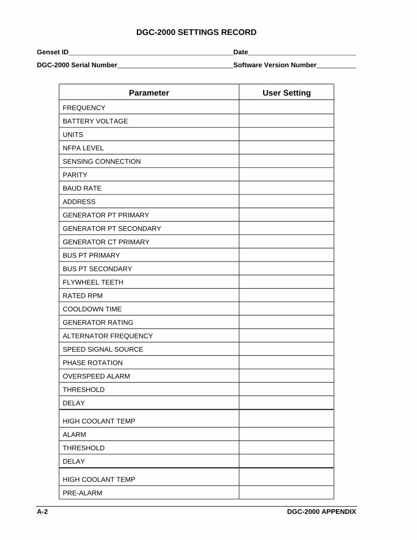
A-2 DGC-2000 APPENDIX
DGC-2000 SETTINGS RECORD
Genset ID Date
DGC-2000 Serial Number Software Version Number
Parameter User Setting
FREQUENCY
BATTERY VOLTAGE
UNITS
NFPA LEVEL
SENSING CONNECTION
PARITY
BAUD RATE
ADDRESS
GENERATOR PT PRIMARY
GENERATOR PT SECONDARY
GENERATOR CT PRIMARY
BUS PT PRIMARY
BUS PT SECONDARY
FLYWHEEL TEETH
RATED RPM
COOLDOWN TIME
GENERATOR RATING
ALTERNATOR FREQUENCY
SPEED SIGNAL SOURCE
PHASE ROTATION
OVERSPEED ALARM
THRESHOLD
DELAY
HIGH COOLANT TEMP
ALARM
THRESHOLD
DELAY
HIGH COOLANT TEMP
PRE-ALARM
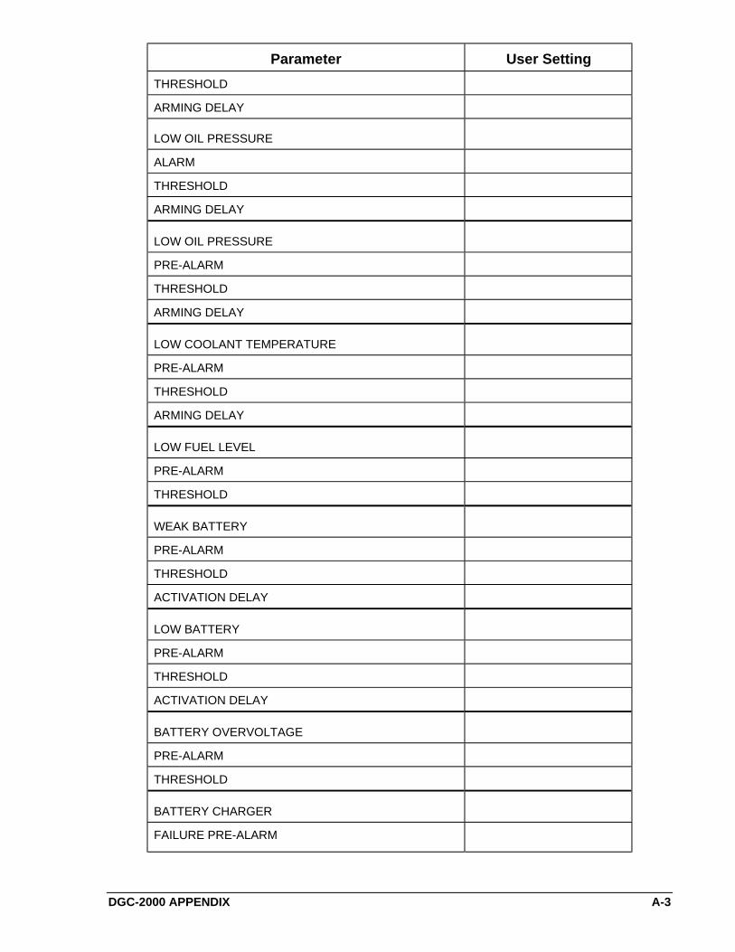
DGC-2000 APPENDIX A-3
Parameter User Setting
THRESHOLD
ARMING DELAY
LOW OIL PRESSURE
ALARM
THRESHOLD
ARMING DELAY
LOW OIL PRESSURE
PRE-ALARM
THRESHOLD
ARMING DELAY
LOW COOLANT TEMPERATURE
PRE-ALARM
THRESHOLD
ARMING DELAY
LOW FUEL LEVEL
PRE-ALARM
THRESHOLD
WEAK BATTERY
PRE-ALARM
THRESHOLD
ACTIVATION DELAY
LOW BATTERY
PRE-ALARM
THRESHOLD
ACTIVATION DELAY
BATTERY OVERVOLTAGE
PRE-ALARM
THRESHOLD
BATTERY CHARGER
FAILURE PRE-ALARM
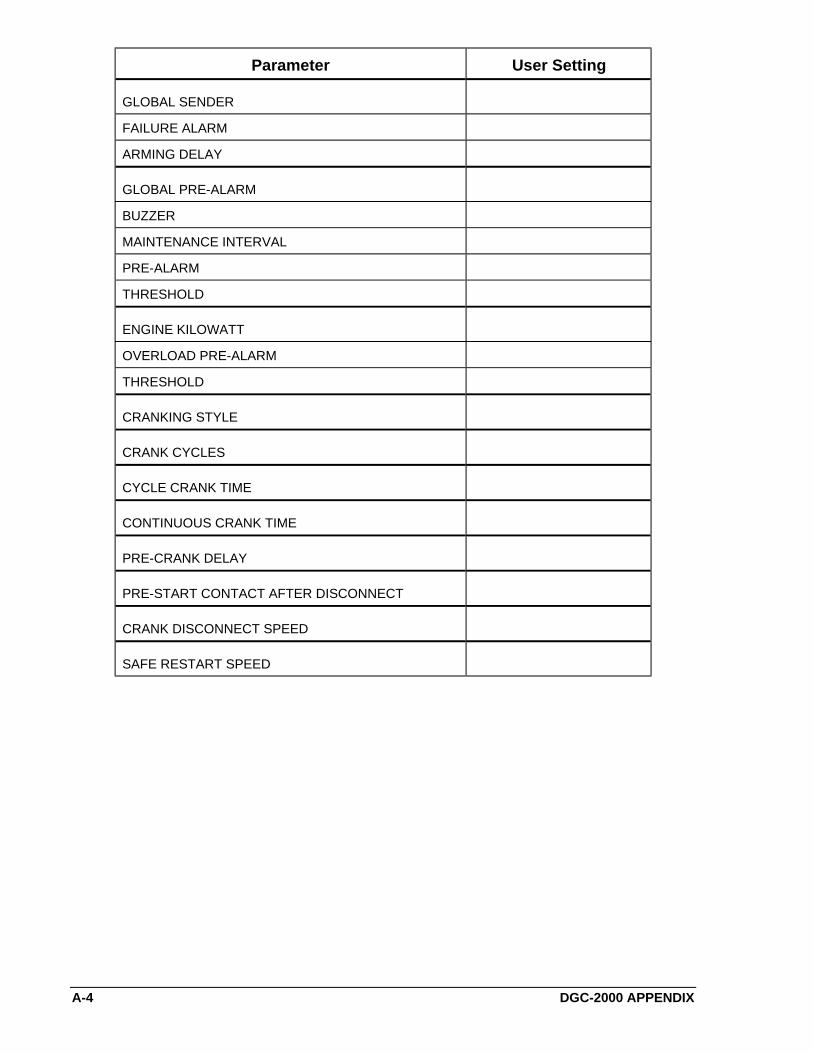
A-4 DGC-2000 APPENDIX
Parameter User Setting
GLOBAL SENDER
FAILURE ALARM
ARMING DELAY
GLOBAL PRE-ALARM
BUZZER
MAINTENANCE INTERVAL
PRE-ALARM
THRESHOLD
ENGINE KILOWATT
OVERLOAD PRE-ALARM
THRESHOLD
CRANKING STYLE
CRANK CYCLES
CYCLE CRANK TIME
CONTINUOUS CRANK TIME
PRE-CRANK DELAY
PRE-START CONTACT AFTER DISCONNECT
CRANK DISCONNECT SPEED
SAFE RESTART SPEED


![INSTRUCTION MANUALmanuals.hobbico.com/hmx/hmxe0210-manual.pdfINSTRUCTION MANUAL Rotor Diameter:27.5 in [700mm] Weight: 19–22 oz [580–760g] Length: 25.4 in [645mm] Height: 9 in](https://static.fdocuments.in/doc/165x107/607a12483c513f15815da72a/instruction-instruction-manual-rotor-diameter275-in-700mm-weight-19a22-oz.jpg)