
Instruction Manual - Omron€¦ · nation with any electrical or electronic components, circuits,...
44
High-function General-purpose Inverter RX2 series (3G3RX2-@@@@@) Instruction Manual PIM 2824133-4A NT3171X OMRON Corporation OMRON Corporation 2019 All Rights Reserved Thank you for purchasing this OMRON Product. Please read this Instruction Manual and User's Manual, and thoroughly familiarize yourself with the functions and characteristics of the product before use. Be sure you are using the most recent version of the User's Manual. Please retain this Instruclion Manual and the User's Manual for future reference, and be sure they are deliv- ered to the final user of the Inverter Drive. User’s Manual I620-E1
Transcript of Instruction Manual - Omron€¦ · nation with any electrical or electronic components, circuits,...

High-function General-purpose Inverter
RX2 series (3G3RX2-@@@@@)
Instruction Manual
PIM 2824133-4ANT3171X
OMRON Corporation OMRON Corporation 2019 All Rights Reserved
Thank you for purchasing this OMRON Product. Please read this InstructionManual and User's Manual, and thoroughly familiarize yourself with thefunctions and characteristics of the product before use. Be sure you are using the most recent version of the User's Manual. Please retain this Instruclion Manual and the User's Manual for future reference, and be sure they are deliv-ered to the final user of the Inverter Drive.
User’s Manual I620-E1

Terms and Conditions Agreement
2
Terms and Conditions Agreement
Exclusive Warranty
Omron’s exclusive warranty is that the Products will be free from defects in materials and workman-ship for a period of twelve months from the date of sale by Omron (or such other period expressed in writing by Omron). Omron disclaims all other warranties, express or implied.
Limitations
OMRON MAKES NO WARRANTY OR REPRESENTATION, EXPRESS OR IMPLIED, ABOUT NON-INFRINGEMENT, MERCHANTABILITY OR FITNESS FOR A PARTICULAR PURPOSE OF THE PRODUCTS. BUYER ACKNOWLEDGES THAT IT ALONE HAS DETERMINED THAT THE PRODUCTS WILL SUITABLY MEET THE REQUIREMENTS OF THEIR INTENDED USE.
Omron further disclaims all warranties and responsibility of any type for claims or expenses based on infringement by the Products or otherwise of any intellectual property right.
Buyer Remedy
Omron’s sole obligation hereunder shall be, at Omron’s election, to (i) replace (in the form originally shipped with Buyer responsible for labor charges for removal or replacement thereof) the non-com-plying Product, (ii) repair the non-complying Product, or (iii) repay or credit Buyer an amount equal to the purchase price of the non-complying Product; provided that in no event shall Omron be responsible for warranty, repair, indemnity or any other claims or expenses regarding the Products unless Omron’s analysis confirms that the Products were properly handled, stored, installed and maintained and not subject to contamination, abuse, misuse or inappropriate modification. Return of any Products by Buyer must be approved in writing by Omron before shipment. Omron Companies shall not be liable for the suitability or unsuitability or the results from the use of Products in combi-nation with any electrical or electronic components, circuits, system assemblies or any other materi-als or substances or environments. Any advice, recommendations or information given orally or in writing, are not to be construed as an amendment or addition to the above warranty.
See http://www.omron.com/global/ or contact your Omron representative for published information.
OMRON COMPANIES SHALL NOT BE LIABLE FOR SPECIAL, INDIRECT, INCIDENTAL, OR CON-SEQUENTIAL DAMAGES, LOSS OF PROFITS OR PRODUCTION OR COMMERCIAL LOSS IN ANY WAY CONNECTED WITH THE PRODUCTS, WHETHER SUCH CLAIM IS BASED IN CONTRACT, WARRANTY, NEGLIGENCE OR STRICT LIABILITY.
Further, in no event shall liability of Omron Companies exceed the individual price of the Product on which liability is asserted.
Warranty, Limitations of Liability
Warranties
Limitation on Liability; Etc

3
Terms and Conditions Agreement
Omron Companies shall not be responsible for conformity with any standards, codes or regulations which apply to the combination of the Product in the Buyer’s application or use of the Product. At Buyer’s request, Omron will provide applicable third party certification documents identifying ratings and limitations of use which apply to the Product. This information by itself is not sufficient for a com-plete determination of the suitability of the Product in combination with the end product, machine, sys-tem, or other application or use. Buyer shall be solely responsible for determining appropriateness of the particular Product with respect to Buyer’s application, product or system. Buyer shall take applica-tion responsibility in all cases.
NEVER USE THE PRODUCT FOR AN APPLICATION INVOLVING SERIOUS RISK TO LIFE OR PROPERTY OR IN LARGE QUANTITIES WITHOUT ENSURING THAT THE SYSTEM AS A WHOLE HAS BEEN DESIGNED TO ADDRESS THE RISKS, AND THAT THE OMRON PRODUCT (S) IS PROPERLY RATED AND INSTALLED FOR THE INTENDED USE WITHIN THE OVERALL EQUIP-MENT OR SYSTEM.
Omron Companies shall not be responsible for the user’s programming of a programmable Product, or any consequence thereof.
Data presented in Omron Company websites, catalogs and other materials is provided as a guide for the user in determining suitability and does not constitute a warranty. It may represent the result of Omron’s test conditions, and the user must correlate it to actual application requirements. Actual perfor-mance is subject to the Omron’s Warranty and Limitations of Liability.
Product specifications and accessories may be changed at any time based on improvements and other reasons. It is our practice to change part numbers when published ratings or features are changed, or when significant construction changes are made. However, some specifications of the Product may be changed without any notice. When in doubt, special part numbers may be assigned to fix or establish key specifications for your application. Please consult with your Omron’s representative at any time to confirm actual specifications of purchased Product.
Information presented by Omron Companies has been checked and is believed to be accurate; how-ever, no responsibility is assumed for clerical, typographical or proofreading errors or omissions.
Application Considerations
Suitability of Use
Programmable Products
Disclaimers
Performance Data
Change in Specifications
Errors and Omissions

Safety Precautions
4
Safety Precautions
Explanation of Symbols
Indicates a potentially hazardous situation which, if not avoided, will result in minor or moderate injury, or may result in serious injury or death. Additionally, there may be significant property damage.
Indicates a potentially hazardous situation which, if not avoided, may result in minor or moderate injury or in property damage.
This symbol indicates a prohibited item (an item you must not do).
The specific instruction is indicated using an illustration or text inside or near .
The symbol shown to the left indicates “disassembly prohibited.”
This symbol indicates danger and caution.
The specific instruction is indicated using an illustration or text inside or near .
The symbol shown to the left indicates “beware of electric shock.”
This symbol indicates danger and caution.
The specific instruction is indicated using an illustration or text inside or near .The symbol shown to the left indicates “non-specific general danger.”
This symbol indicates caution (including warning).
The specific instruction is indicated using an illustration or text inside or near .The symbol shown to the left indicates “risk of hot surface.”
This symbol indicates a compulsory item (an item that must be done).
The specific instruction is indicated using an illustration or text inside or near .
The symbol shown to the left indicates “general compulsory items.”
This symbol indicates a compulsory item (an item that must be done).
The specific instruction is indicated using an illustration or text inside or near .
The symbol shown to the left indicates “grounding required.”
5
Safety Precautions
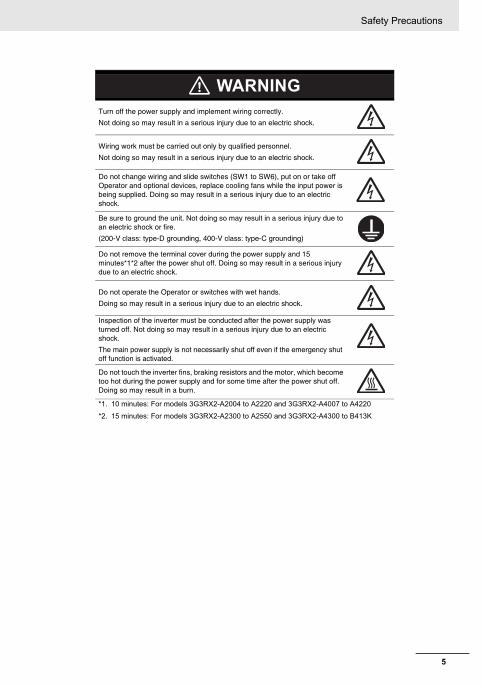
Turn off the power supply and implement wiring correctly.
Not doing so may result in a serious injury due to an electric shock.
Wiring work must be carried out only by qualified personnel.
Not doing so may result in a serious injury due to an electric shock.
Do not change wiring and slide switches (SW1 to SW6), put on or take off Operator and optional devices, replace cooling fans while the input power is being supplied. Doing so may result in a serious injury due to an electric shock.
Be sure to ground the unit. Not doing so may result in a serious injury due to an electric shock or fire.
(200-V class: type-D grounding, 400-V class: type-C grounding)
Do not remove the terminal cover during the power supply and 15 minutes*1*2 after the power shut off. Doing so may result in a serious injury due to an electric shock.
Do not operate the Operator or switches with wet hands.
Doing so may result in a serious injury due to an electric shock.
Inspection of the inverter must be conducted after the power supply was turned off. Not doing so may result in a serious injury due to an electric shock.
The main power supply is not necessarily shut off even if the emergency shut off function is activated.
Do not touch the inverter fins, braking resistors and the motor, which become too hot during the power supply and for some time after the power shut off. Doing so may result in a burn.
*1. 10 minutes: For models 3G3RX2-A2004 to A2220 and 3G3RX2-A4007 to A4220
*2. 15 minutes: For models 3G3RX2-A2300 to A2550 and 3G3RX2-A4300 to B413K
WARNING

Safety Precautions
6
Be sure to confirm safety before conducting maintenance, inspection or parts replacement.
Do not connect resistors to the terminals (PD/+1, P/+, N/-) directly. Doing so might result in a small-scale fire, heat generation, or damage to the unit.
Install a stop motion device to ensure safety. Not doing so might result in a minor injury. (A holding brake is not a stop motion device designed to ensure safety.)
Be sure to use a specified type of braking resistor/regenerative braking unit. In case of a braking resistor, install a thermal relay that monitors the temperature of the resistor. Not doing so might result in a moderate burn due to the heat generated in the braking resistor/regenerative braking unit. Configure a sequence that enables the inverter power to turn off when unusual over eating is detected in the braking resistor/regenerative braking unit.
The inverter has high voltage parts inside which, if short-circuited, might cause damage to itself or other property. Place covers on the openings or take other precautions to make sure that no metal objects such as cutting bits or lead wire scraps go inside when installing and wiring.
Take safety precautions such as setting up a molded-case circuit breaker (MCCB) that matches the inverter capacity on the power supply side.
Not doing so might result in damage to property due to the short circuit of the load.
Do not dismantle, repair or modify the product.
Doing so may result in an injury.
If a parameter is set incorrectly when starting up, adjusting, maintaining, or replacing, an unexpected operation may occur.
If the DriveProgramming stops during multi-function output, the output status is held. Take safety precautions such as stopping peripheral devices.
CAUTION

7
Precautions for Safe Use
Precautions for Safe Use
Do not store or use the product in the following places.• Locations subject to direct sunlight.• Locations subject to ambient temperature exceeding the specifications.• Locations subject to relative humidity exceeding the specifications.• Locations subject to condensation due to severe temperature fluctuations.• Locations subject to corrosive or flammable gases.• Locations subject to exposure to combustibles.• Locations subject to dust (especially iron dust) or salts.• Locations subject to exposure to water, oil, or chemicals.• Locations subject to shock or vibration.
• Do not drop or apply strong impact on the product. Doing so may result in damaged parts or malfunction.
• Do not hold by the front cover and terminal cover, but hold by the fins during transportation.• Confirm that the rated input voltage of the inverter is the same as AC power supply voltage.• Do not connect an AC power supply voltage to the control input/output terminals. Doing so may result
in damage to the product.• Be sure to tighten the screws on the terminal block securely. Wiring work must be done after
installing the unit body.• Do not connect any load other than a three-phase inductive motor to the U, V, and W output
terminals.• Take sufficient shielding measures when using the product in the following locations. Not doing so
may result in damage to the product.
Locations subject to static electricity or other forms of noise.
Locations subject to strong magnetic fields.
Locations close to power lines.• When using DriveProgramming, confirm that the program data is downloaded normally before
starting operation.
Installation and Storage
Transportation, Installation, and Wiring

Precautions for Safe Use
8
• Be sure to confirm the permissible range of motors and machines before operation because the inverter speed can be changed easily from low to high.
• Provide a separate holding brake if necessary.• If the clock command is used in DriveProgramming, an unexpected operation may occur due to weak
battery. Take measures such as detecting a weak battery by [E042] RTC Error and stopping the inverter or programs. When the LCD Operator is removed or disconnected, DriveProgramming is in a waiting status by the clock command.
• Be sure to confirm the RUN signal is turned off before resetting the alarm because the machine may abruptly start.
• Do not come close to the machine when you enable "restart" setting that results in automatic start after a deceleration stop, (bA-30, bb-20, bb-21) the machine may abruptly start after the power is turned on.
• Provide a separate emergency stop switch because the STOP Key on the Operator is valid only when function settings are performed.
• When checking a signal during the power supply and the voltage is erroneously applied to the control input terminals, the motor may start abruptly. Be sure to confirm safety before checking a signal.
• Check whether the motor rotation direction is correct and unusual sound or vibration occurs during operation.
• The capacitor service life is influenced by the ambient temperature. Refer to “Smoothing Capacitor Life Curve” described in the manual. When a capacitor reaches the end of its service life and does not work as the product, you need to replace the capacitor.
• When disposing of LCD operators and wasted batteries, follow the applicable ordinances of your local government. When disposing of the battery, insulate it using tape.
• Do not short + and –, charge, disassemble, heat, put into the fire, or apply strong impact on the battery. The battery may leak, explode, produce heat or fire. Never use the battery which was applied strong impact due to such as fall on the floor, it may leak.
• UL standards establish that the battery shall be replaced by an expert engineer. The expert engineer must be in charge of the replacement and also replace the battery according to the method described in this manual.
• When the display of LCD Operator can not be recognized due to the service life, replace the LCD Operator.
Operation and Adjustment
Maintenance and Inspection
The following display must be indicated when products using lithium primary batteries (withmore than 6 ppb of perchlorate) are transport to or through the State of California, USA.
Perchlorate Material - special handling may apply.See www.dtsc.ca.gov/hazardouswaste/perchlorate
Label or mark the above display on the exterior of all outer shipping packages of your prod-ucts when exporting your products which the lithium primary batteries (with more than 6 ppbof perchlorate) are installed to the State of California, USA.

9
Precautions for Correct Use
Precautions for Correct Use
Mount the product vertically on a wall with the product’s longer sides upright.
The material of the wall must be noninflammable such as a metal plate.
• Confirm that the power voltage for the encoder is the same as the rated voltage (+12V DC or +5V DC) of the product.
• Do not come close to the machine when using Instantaneous power failure/ under-voltage trip (bb-24) or over-current (bb-28) because the machine may abruptly start after the alarm cleared.
• Generally speaking, inverters contain components and will operate properly only when each compo-nent operates normally. Some of the electrical components require maintenance depending on appli-cation conditions. Periodic inspection and replacement are necessary to ensure proper long-term operation of Inverters.
• When a cooling fan reaches the end of its service life, replace it.
Comply with the local ordinance and regulations when disposing of the product.
Installation
Installation and Wiring
Restart Selection Function
Maintenance and Parts Replacement
Product Disposal
Dispose of in accordance with WEEE Directive
Nomenclature
10
Nomenclature
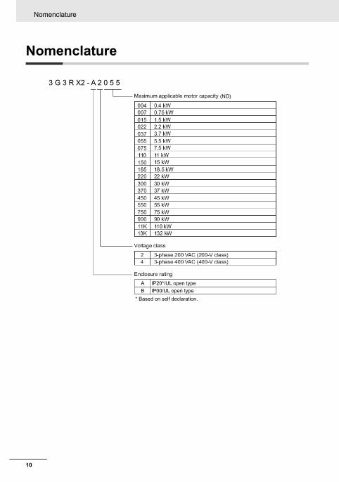
3 G 3 R X2 - A 2 0 5 5
(ND)
IP20*/UL open typeAB IP00/UL open type
* Based on self declaration.

11
Inverter Specifications
Inverter Specifications
Inverter Specifications
200V Class Specifications
*1. The rated input currents shown in the table are the values when the rated current is output. The values vary depending on impedance on the power supply (wiring, breaker, input reactor option, etc.) Select peripheral devices that have enough margin with reference to these values, which are different from ones shown on the product nameplate.
*2. The power supply equipment capacities shown in the table are the values when 220V rated current is output. The values vary depending on impedance on the power supply (wiring, breaker, input reactor option, etc.)
*3. The setting of rated values for carrier frequencies [bb101]/[bb201] are internally limited in accordance with the description. Also, it is recommended to set values equivalent to or above (maximum output frequency for driving ×10) Hz for the setting of carrier frequencies [bb101]/[bb201]. Also, in the case of induction motor (IM) control, for items other than those subject to V/f control, it is recommended to set carrier frequency at 2kHz or more. In the case of synchronous motor (SM)/permanent magnet motor (PMM) control, it is recommended to set carrier frequency at 8kHz or more.
*4. The value of the sensor-less vector control applied to the ND rating in the Standard motor. Torque characteristics may vary depending on the control method and the motor used.
*5. Based on self declaration.
3G3RX2-A2 A2004 A2007 A2015 A2022 A2037 A2055 A2075 A2110 A2150 A2185 A2220 A2300 A2370 A2450 A2550
Applicable motor (4-pole) capacity (kW)
VLD 0.75 1.5 2.2 3.7 5.5 7.5 11 15 18.5 22 30 37 45 55 75
LD 0.75 1.5 2.2 3.7 5.5 7.5 11 15 18.5 22 30 37 45 55 75
ND 0.4 0.75 1.5 2.2 3.7 5.5 7.5 11 15 18.5 22 30 37 45 55
Output
Rated output current (A)
VLD 4.4 8.0 10.4 15.6 22.8 33.0 46.0 60.0 80.0 93.0 124 153 185 229 295
LD 3.7 6.3 9.4 12.0 19.6 30.0 40.0 56.0 73.0 85.0 113 140 169 210 270
ND 3.2 5.0 8.0 11.0 17.5 25.0 32.0 46.0 64.0 76.0 95.0 122 146 182 220
Overload current rating
VLD 110% 60sec / 120% 3sec
LD 120% 60sec / 150% 3sec
ND 150% 60sec / 200% 3sec
Rated output voltage 3-phase (3-wire) 200 to 240V (depending on receiving voltage)
Rated capacity (kVA)
200V
VLD 1.5 2.8 3.6 5.4 7.9 11.4 15.9 20.8 27.7 32.2 43.0 53.0 64.1 79.3 102.2
LD 1.3 2.2 3.3 4.2 6.8 10.4 13.9 19.4 25.3 29.4 39.1 48.5 58.5 72.7 93.5
ND 1.1 1.7 2.8 3.8 6.1 8.7 11.1 15.9 22.2 26.3 32.9 42.3 50.6 63.0 76.2
240V
VLD 1.8 3.3 4.3 6.5 9.5 13.7 19.1 24.9 33.3 38.7 51.5 63.6 76.9 95.2 122.6
LD 1.5 2.6 3.9 5.0 8.1 12.5 16.6 23.3 30.3 35.3 47.0 58.2 70.3 87.3 112.2
ND 1.3 2.1 3.3 4.6 7.3 10.4 13.3 19.1 26.6 31.6 39.5 50.7 60.7 75.7 91.5
Input
Rated input current (A) *1
VLD 5.2 9.5 12.4 18.6 27.1 39.3 54.8 71.4 95.2 110.7 147.6 182.1 220.2 272.6 351.2
LD 4.4 7.5 11.2 14.3 23.3 35.7 47.6 66.7 86.9 101.2 134.5 166.7 201.2 250.0 321.4
ND 3.8 6.0 9.5 13.1 20.8 29.8 38.1 54.8 76.2 90.5 113.1 145.2 173.8 216.7 261.9
Rated input AC voltage
Control power supply: Power supply single phase 200 to 240V/allowable variation range 170 to 264V, 50Hz (allowable variation range: 47.5 to 52.5Hz)/60Hz (allowable variation range: 57 to 63Hz)
Main circuit power supply: 3-phase (3-wire) 200 to 240V/allowable variation range 170 to 264V, 50Hz (allowable variation range: 47.5 to 52.5Hz)/60Hz (allowable variation range: 57 to 63Hz)
Power supply equipment capacity (kVA) *2
VLD 2.0 3.6 4.7 7.1 10.3 15.0 20.9 27.2 36.3 42.2 56.3 69.4 83.9 103.9 133.8
LD 1.7 2.9 4.3 5.4 8.9 13.6 18.1 25.4 33.1 38.6 51.3 63.5 76.7 95.3 122.5
ND 1.5 2.3 3.6 5.0 7.9 11.3 14.5 20.9 29.0 34.5 43.1 55.3 66.2 82.6 99.8
Carrier frequency operating range *3
VLD 0.5 to 10.0kHz
LD 0.5 to 12.0kHz
ND 0.5 to 16.0kHz
Motor start torque *4 200%/0.3Hz
Braking
Regenerative braking Equipped with BRD circuit (with a discharging resistor separately installed)Regenerative braking unit
separately installed
Minimum resistance that can be connected (Ω)
50 50 35 35 35 16 10 10 7.5 7.5 5 --- --- --- ---
Protective construction IP20*5 / UL open type
Approximate mass (kg) 3 3 3 3 3 6 6 6 10 10 10 22 33 33 47

Inverter Specifications
12
400V Class Specifications
*1. The rated input currents shown in the table are the values when the rated current is output. The values vary depending on impedance on the power supply (wiring, breaker, input reactor option, etc.) Select peripheral devices that have enough margin with reference to these values, which are different from ones shown on the product nameplate.
*2. The power supply equipment capacities shown in the table are the values when 220V rated current is output. The values vary depending on impedance on the power supply (wiring, breaker, input reactor option, etc.)
*3. The setting of rated values for carrier frequencies [bb101]/[bb201] are internally limited in accordance with the description. Also, it is recommended to set values equivalent to or above (maximum output frequency for driving ×10) Hz for the setting of carrier frequencies [bb101]/[bb201]. Also, in the case of induction motor (IM) control, for items other than those subject to V/f control, it is recommended to set carrier frequency at 2kHz or more. In the case of synchronous motor (SM)/permanent magnet motor (PMM) control, it is recommended to set carrier frequency at 8kHz or more.
*4. The value of the sensor-less vector control applied to the ND rating in the Standard motor. Torque characteristics may vary depending on the control method and the motor used.
*5. Based on self declaration.
3G3RX2- A4007 A4015 A4022 A4037 A4055 A4075 A4110 A4150 A4185 A4220 A4300 A4370 A4450 A4550 B4750 B4900 B411K B413K
Applicable motor (4-pole) capacity (kW)
VLD 1.5 2.2 3.7 5.5 7.5 11 15 18.5 22 30 37 45 55 75 90 110 132 160
LD 1.5 2.2 3.7 5.5 7.5 11 15 18.5 22 30 37 45 55 75 90 110 132 160
ND 0.75 1.5 2.2 3.7 5.5 7.5 11 15 18.5 22 30 37 45 55 75 90 110 132
Output
Rated output current (A)
VLD 4.1 5.4 8.3 12.6 17.5 25.0 31.0 40.0 47.0 62.0 77.0 93.0 116 147 176 213 252 316
LD 3.1 4.8 6.7 11.1 16.0 22.0 29.0 37.0 43.0 57.0 70.0 85.0 105 135 160 195 230 290
ND 2.5 4.0 5.5 9.2 14.8 19.0 25.0 32.0 39.0 48.0 61.0 75.0 91.0 112 150 180 217 260
Overload current rating
VLD 110% 60sec / 120% 3sec
LD 120% 60sec / 150% 3sec
ND 150% 60sec / 200% 3sec
Rated output voltage
3-phase (3-wire) 380 to 500V (depending on receiving voltage)
Rated capacity (kVA)
400V
VLD 2.8 3.7 5.8 8.7 12.1 17.3 21.5 27.7 32.6 43.0 53.3 64.4 80.4 101.8 121.9 147.6 174.6 218.9
LD 2.1 3.3 4.6 7.7 11.1 15.2 20.1 25.6 29.8 39.5 48.5 58.9 72.7 93.5 110.9 135.1 159.3 200.9
ND 1.7 2.8 3.8 6.4 10.3 13.2 17.3 22.2 27.0 33.3 42.3 52.0 63.0 77.6 103.9 124.7 150.3 180.1
500V
VLD 3.6 4.7 7.2 10.9 15.2 21.7 26.8 34.6 40.7 53.7 66.7 80.5 100.5 127.3 152.4 184.5 218.2 273.7
LD 2.7 4.2 5.8 9.6 13.9 19.1 25.1 32.0 37.2 49.4 60.6 73.6 90.9 116.9 138.6 168.9 199.2 251.1
ND 2.2 3.5 4.8 8.0 12.8 16.5 21.7 27.7 33.8 41.6 52.8 65.0 78.8 97.0 129.9 155.9 187.9 225.2
Input
Rated input current (A) *1
VLD 4.9 6.4 9.9 15.0 20.8 29.8 36.9 47.6 56.0 73.8 91.7 110.7 138.1 175.0 209.5 253.6 300.0 376.2
LD 3.7 5.7 8.0 13.2 19.0 26.2 34.5 44.0 51.2 67.9 83.3 101.2 125.0 160.7 190.5 232.1 273.8 345.2
ND 3.0 4.8 6.5 11.0 17.6 22.6 29.8 38.1 46.4 57.1 72.6 89.3 108.3 133.3 178.6 214.3 258.3 309.5
Rated input AC voltage
Control power supply: Power supply single phase 380 to 500V (allowable variation range 323 to 550V), 50Hz (allowable variation range: 47.5 to 52.5Hz)/60Hz (allowable variation range: 57 to 63Hz)
Main circuit power supply: 3-phase (3-wire) 380 to 500V (allowable variation range) 323 to 550V, 50Hz (allowable variation range: 47.5 to 52.5Hz)/60Hz (allowable variation range: 57 to 63Hz)
Power supply equipment capacity (kVA) *2
VLD 3.7 4.9 7.5 11.4 15.9 22.7 28.1 36.3 42.6 56.3 69.9 84.4 105.2 133.4 159.7 193.2 228.6 286.7
LD 2.8 4.4 6.1 10.1 14.5 20.0 26.3 33.6 39.0 51.7 63.5 77.1 95.3 122.5 145.2 176.9 208.7 263.1
ND 2.3 3.6 5.0 8.3 13.4 17.2 22.7 29.0 35.4 43.5 55.3 68.0 82.6 101.6 136.1 163.3 196.9 235.9
Carrier frequency range *3
VLD 0.5 to 10.0kHz 0.5 to 8.0kHz
LD 0.5 to 12.0kHz 0.5 to 8.0kHz
ND 0.5 to 16.0kHz 0.5 to 10.0kHz
Motor start torque *4 200%/0.3Hz 180%/0.3Hz
Braking
Regenerative braking
Equipped with braking resistance circuit (with a discharging resistor separately installed)
Regenerative braking unit separately installed
Minimum resistance that can be connected (Ω)
100 100 100 70 70 35 35 24 24 20 15 15 - - - - - -
Protective construction IP20*5 / UL open type IP00 / UL open type
Approximate mass (kg) 3 3 3 3 6 6 6 8.5 8.5 8.5 22 31 31 31 41 41 53 53

13
Inverter Specifications
Common Specification
*1. The output frequency range depend on the control and motor used. When running the inverter exceeding 60Hz, check the maximum allowable frequency with the manufacturer of the motor.
*2. When the control mode is changed, unless the motor constant is appropriately configured, you cannot obtain the desired starting torque or the inverter may trip.
*3. The variable range of motor speed may vary depending on your system or the environment where the motor is used. Please contact us for details.*4. Both the input power and output power are reference values, which are not appropriate for use in calculation of efficiency values, etc. To obtain an accurate
value, use an external device.*5. The IGBT error [E030] is generated by the protective function not only for short circuit protection but also when IGBT is damaged. Depending on the oper-
ating conditions of the inverter, the overcurrent error [E001] may occur, instead of the IGBT error.*6. At the factory default setting, when voltage and current on Ai1/Ai2 terminal is changed using a switch, with input of voltage at 9.8V and current at 19.8mA,
the maximum frequency is commanded. To change characteristics, make adjustments using the analog start/end function.
Control mode (output to the motor) Sine wave PWM control voltage output (line sine wave modulation)
Output frequency range *1 0.00 to 590.00Hz
Frequency accuracy Digital command ±0.01% and analog command ±0.2% (25°C±10°C) against the maximum frequency
Frequency resolutionDigital setting: 0.01HzAnalog setting: maximum frequency/4000 (Ai1 terminal/Ai2 terminal: 12bit/0 to +10V or 0 to +20mA, Ai3 terminal 12bit/-10 to +10V)
Control mode (frequency/voltage calculation) *2
IM V/f control (fixed torque/reduced torque/free), automatic boost control, cascade model sensorless vector control, 0 Hz range sensorless vector control, vector control with sensor.
SM/PMM Synchronous starting sensorless vector control, IVMS starting smart sensorless vector control
Speed fluctuation *3 ±0.5% (during sensorless vector control)
Acceleration or deceleration time 0.00 to 3600.00sec (linear, S-shaped, U-shaped, reverse U-shaped, EL-S shaped)
Display monitor Output frequency, output current, output torque, trip history, I/O terminal status, I/O power *4, P-N voltage and others described in "Chapter 13 Information Monitoring Functions".
Starting functions Start after DC braking, frequency collection start, frequency entrainment start, reduced voltage start, retry start
Stopping functions Free-run stop, DC braking after deceleration stop or terminal DC braking (braking power, operating speed adjustment)
Stall prevention function Overload restraining function, overcurrent suppression function, overvoltage suppression function
Protective function *5
Overcurrent error, Motor overload error, Braking resister Overload error, Overvoltage error, Memory error, Undervoltage error, Current detector error, CPU error, External trip error, USP error, Ground fault error, Incoming over voltage error, Instantaneous power failure error, Temperature detector error, Cooling fan rotation speed reduction temperature error, Temperature error, Input open-phase error, IGBT error, Output open-phase error, Thermistor error, Brake error, Low-speed range overload error, Controller overload error, RS485 communication error, Operator keypad disconnection error.
Other functions
V/f free settings (7 points), Upper/lower limit frequency limiter, Frequency jump, Curve acceleration/deceleration, Manual torque boost, Energy-saving operation, Analog output adjustment function, Minimum frequency, Carrier frequency adjustment, Motor electronic thermal function (free setting is also possible), Inverter electronic thermal function, External start/end (volume/ratio), Frequency input selection, Trip retry, Restart after instantaneous stop, Output of signals, Initialization settings, PID control, Automatic deceleration at power shut-off, Brake control function, and Auto-tuning for commercial switching function (online/offline).
Input
Frequency setting
Standard operator keypad Parameter setting using arrow keys
External signals *6
Ai1/Ai2 terminal (when changing voltage) Setting through input of 0 to 10VDC voltage (input impedance: 10kΩ)
Ai1/Ai2 terminal (when changing current) Setting through input of 0 to 20mA current (input impedance: 100Ω)
Ai3 terminal Setting through input of -10 to +10V voltage (input impedance: 10kΩ)
Multistage speed terminal (use of input terminal function) 15 speed
Pulse string input (A/B terminal, use of input terminal function)
32kHz×2 at maximum
External port Setting via RS485 serial communication (protocol: Modbus-RTU)
Normal rotation/reverse rotationRun/stop
Standard operator keypad
Execution with the RUN /STOP key (normal rotation/reverse rotation can be switched by setting parameters)
External signals
Normal rotation operation (FW)/reverse rotation (RV) (when an input terminal function is assigned)3-wire input available (when an input terminal function is assigned)
External port Setting via RS485 serial communication (protocol: Modbus-RTU (maximum: 115.2kbps)
Input terminal function
11 terminals (input of pulse string is available on terminal A and B)
FW (Normal rotation)/RV (Reverse rotation), CF1-4 (Multistage speed 1-4), SF1-7 (Multistage speed bit 1-7), ADD (Addition of frequency), SCHG (Switching of frequency command), STA (3-wire start)/STP (3-wire stop)/F_R (3-wire normal/reverse), AHD (Retention of analog command), FUP (Increase of speed via remote operation/FDN (Deceleration via remote operation), UDC (Deletion of data via remote operation), F-OP (Forced command switching), SET (Second control), RS (Reset), JG (Jogging), DB (External current braking), 2CH (2-stage acceleration/deceleration), FRS (Free-run stop), EXT (External abnormality), USP (Prevention of restart after restoration of power), CS (Commercial switching), SFT (Soft-lock), BOK (Brake check), OLR (Overload restriction switching), KHC (Clearance of integrated input power), OKHC (Clearance of integrated output power), PID (PID1 disabled), PIDC (PID1 integration reset), PID2 (PID2 disabled), PIDC2 (PID2 integration reset), SVC1-4 (PID1 multistage target values 1-4), PRO (PID gain switching), PIO (PID output switching), SLEP (SLEEP condition satisfied)/WAKE (WAKE condition satisfied), TL (Torque restriction enabled), TRQ1, 2 (Switching of torque limit 1,2), PPI (Switching of P/PI control), CAS (Switching of control gain), FOC (Preparatory excitation), ATR (Torque control enabled), TBS (Torque bias enabled), LAC (Cancellation of acceleration/deceleration), Mi1-11 (General-purpose input 1-11), PCC (Clearance of pulse counter), ECOM (Start of EzCOM), PRG (Program run), HLD (Acceleration/deceleration stop), REN (Operation permission signal), PLA (Pulse string input A), and PLB (Pulse string input B)
Backup power supply terminal P+/P-: DC24V input (allowable input voltage: 24V±10%)
STO input terminal 2 terminals (simultaneous input)
Thermistor input terminal 1 terminal (possible to switch between positive temperature coefficient/negative temperature coefficient resistance element)

Inverter Specifications
14
Common specifications (continued)
*7. The threshold for signal output varies depending on the motor to be combined with the inverter, parameter adjustment, etc.
*8. The output data of analog voltage monitor and analog current monitor are reference values for connecting an analog meter. Due to the meter to be con-nected and variation in analog output circuit, the maximum output value may slightly vary from 10V or 20mA. To change characteristics, make adjustments using the Ao1 adjustment and Ao2 adjustment functions. Some monitor data cannot be output.
*9. To enable the EMC filter, connect with a power supply grounded at a neutral point. Otherwise, the leakage current may increase.
*10. The storage temperature is the temperature during transport.
*11. To be in accordance with the testing method specified in JIS C 60068-2-6: 2010 (IEC 60068-2-6:2007)
*12. When the inverter is used in a location at 1000m or higher altitude, air pressure reduces approximately 1% every 100m elevation. Perform 1% current der-ating and conduct evaluation for every 100m elevation. Please contact us for use in 2500m or higher environments.
*13. For insulation distance, comply with UL and CE standards
*14. Use the 400V class inverter at an input voltage of 500VAC or below. If input voltage exceeds 500VAC due to fluctuation of power, use the inverter at 40°C or lower ambient temperature.
*15. In the case where a clock function is used, a battery (Option:CR2032, 3V) is required. When you purchase the product, the LCD operator does not have its battery.
Applicable Standards
Output
Output terminal function
Transistor output 5 terminal, 1a contact relay 1 point, 1c contact relay 1 point
RUN (During operation), FA1-5 (Reached signal), IRDY (Operation ready completion), FWR (During normal rotation operation), RVR (During reverse rotation operation), FREF (Frequency command operator keypad), REF (Operation command operator keypad), SETM (Second control under selection), AL (Alarm signal), MJA (Severe failure signal), OTQ (Over torque) *7, IP (During instantaneous power failure), UV (Under insufficient voltage), TRQ (During torque limitation), IPS (During power failure deceleration), RNT (RUN time over), ONT (Power on time over), THM (Electronic thermal warning), THC (Electronic thermal warning), WAC (Capacitor life advance notice), WAF (Fan life advance notice), FR (Operation command signal), OHF (Cooling fin heating advance notice), LOC/LOC2 (Low-current signal), OL/OL2 (Overload advance notice), BRK (Brake release), BER (Brake abnormality), ZS (Zero-speed detection signal), OD/OD2 (PID deviation excessive), FBV/FBV2 (PID feedback comparison), NDc (Communication disconnection), Ai1Dc/Ai2Dc/Ai3Dc (Analog disconnection Ai1/Ai2/Ai3), WCAi1/WCAi2/WCAi3 (Window comparator Ai1/Ai2/Ai3), LOG1-7 (Logical operation result 1-7), MO1-7 (General output 1-7), and OVS (Receiving overvoltage).
Relay and alarm relay (1a, 1c)
EDM output terminal Output for STO diagnosis
Monitor output terminal *8 Possible to output through selection from monitor data of parameters
EMC filter switching *9 Possible to enable the EMC noise filter (switching method is different depending on the model)
External access to PC USB Micro-B
Use environment
Ambient temperature *14ND (normal duty) -10 to 50°C
LD (low duty) -10 to 45°C
VLD (very low duty) -10 to 40°C
Storage temperature *10 -20 to 65°C
Humidity 20-90%RH (location free of condensation)
Vibration *11 5.9m/s2 (0.6G) 10 to 55Hz : 3G3RX2-A2004 to A2220 / 3G3RX2-A4007 to A4220
2.94m/s2 (0.3G) 10 to 55Hz : 3G3RX2-A2300 to A2550 / 3G3RX2-A4300 to A413K
Use location *12 1000 m altitude or lower (location free from corrosive gas, oil mist, and dust)
Expected Life timeSmoothing capacitor 10 years
Designed life of cooling fan 10 years (models equipped with a cooling fan) free from dust
Memory element on the control circuit board
Applicable standards *13 Compliance with UL/cUL/CE standards, RCM, Functional Safety SIL3/PLe (to be obtained)
Painting color Black
Operation and monitor LCD operator *15
Number of option slots 3 ports
Other options Braking resistor, AC reactor, DC reactor, noise filter
Markings Standards
CE
EMC EN 61800-3:2004+A1:2012
MachineryIEC61800-5-2:2016 STO SIL3
ISO13849-1:2015 Cat.4 PLe
IEC61800-5-1/A1:2016
UL
US UL61800-5-1
CA CSA C22.2 No. 274
FSIEC61800-5-2:2016 STO SIL3
ISO13849-1:2015 Cat.4 PLe
KC KN61800-3
EAC -
RCM EN 61800-3:2004+A1:2012

15
Inverter Specifications
External dimensions (mm)
3G3RX2- W W1 H H1 D
200 V Class:
400 V Class:
3G3RX2-A2004, 3G3RX2-A2007, 3G3RX2-A2015,3G3RX2-A2022, 3G3RX2-A20373G3RX2-A4007, 3G3RX2-A4015, 3G3RX2-A4022, 3G3RX2-A4037
150 130 255 241 140
200 V Class:400 V Class:
3G3RX2-A2055, 3G3RX2-A2075, 3G3RX2-A21103G3RX2-A4055, 3G3RX2-A4075, 3G3RX2-A4110
210 189 260 246 170
200 V Class:400 V Class:
3G3RX2-A2150, 3G3RX2-A2185, 3G3RX2-A22203G3RX2-A4150, 3G3RX2-A4185, 3G3RX2-A4220
245 229 390 376 190
200 V Class:400 V Class:
3G3RX2-A23003G3RX2-A4300
300 265 540 510 195
200 V Class:400 V Class:
3G3RX2-A2370, 3G3RX2-A24503G3RX2-A4370, 3G3RX2-A4450, 3G3RX2-A4550
390 300 550 520 250
200 V Class: 3G3RX2-A2550 480 380 700 670 250
400 V Class: 3G3RX2-B4750, 3G3RX2-B4900 390 300 700 670 270
400 V Class: 3G3RX2-B411K, 3G3RX2-B413K 480 380 740 710 270
WW1
H1 H
D
2-ø7

Inverter Specifications
16
Precaution on InstallationWhen you use an inverter of 3G3RX2-A2110 at Low Duty (LD) / Very Low Duty (VLD) or you use an inverter of 3G3RX2-A2220 at Very Low Duty (VLD), install it with precautions shown in the following fig-ures. Follow the below procedures and make the setting on your own.
* Set Low Duty [Ub-03] to 01 (LD) and set Very Low Duty to 00 (VLD) to complete the change.
Installation Procedure
Screw
Procedure (1) Procedure (2)
Procedure (3)
Procedure (3)
Procedure (4)
Procedure (4)
Screw
User’s Screw
User’s Screw
Wall
Wall
Plan view / Cross-section view

17
Inverter Specifications
In the case of 3G3RX2-A2220
* Set Very Low Duty to 00 (VLD) to complete the change.
Installation Procedure
Procedure (1) M3×8 Screw Procedure (1)
Procedure (1)
Procedure (2)
Procedure (2)
Spacer
Spacer
User’s Screw
User’s Screw
M3×8 Screw
Wall
Wall
Plan view / Cross-section view

Installation conditions
18
Installation conditions
Equipment Peripheral Dimension Conditions
Please note the installation method, the direction of installation!
• If the inverter is not installed vertically, its cooling performance may be degraded and tripping or inverter damage may result.
• Install the inverter vertically and securely with screws or bolts on a surface that can bear the inverter weight and is free from vibrations.
Surface on which to install the inverter
• The inverter will reach a high temperature (up to about 150°C) during operation. Install the inverter on a vertical wall surface made of nonflammable material (e.g., metal) to avoid the risk of fire. In addition be sure to confirm the structure to bear the Inverter weight.
• Keep sufficient distance between the inverter and other heat sources (e.g., braking resistors and reactors) so that the heat discharged from the heat sources does not affect the inverter.
Screw clamp Screw clamp
Screw clamp Screw clamp
30 cm or more
30 cm or more
5 cm or more
5 cm or more
5 cm or more
5 cm or more
10 cm or more
10 cm or more *1
*1 The following models need minimum 22 cm for maintenance. · 3G3RX2-A2150 to 3G3RX2-A2220 · 3G3RX2-A4150 to 3G3RX2-A4220 The following models needs to be removed to replace aged parts. · 3G3RX2-A2055 to 3G3RX2-A2110 · 3G3RX2-A4055 to 3G3RX2-A4110
3G3RX2-A2004 to 3G3RX2-A25503G3RX2-A4007 to 3G3RX2-A4550
3G3RX2-B4750 to 3G3RX2-B413K

19
Installation conditions
HumidityAvoid installing the inverter in a place where the relative humidity goes above or below the allowable range (20% to 90% RH), as defined by the standard inverter specification. Avoid a place where the inverter is subject to condensation.
Condensation inside the inverter will result in short circuits and malfunctioning of electronic parts. Also avoid places where the inverter is exposed to direct sunlight.
Control circuit terminal block
USB(Micro-B)
LCD operator
Optional cassette installed
Specification label
Main circuit terminal blockBacking plate
Terminal block cover
Heat sink
Air flow
Wall Keep enough clearance between the inverter and the wiring ducts located above and below the Inverter to prevent the latter from obstructing the ventilation of the inverter.
Inve
rter

Main circuit
20
Main circuit
Main circuit Wiring Diagram
*1. A Fuse is appleable in place of ELB.
*2. Driving a 200V motor using a 400V-class inverter may burn the motor.
*3. Factory setting is "Enable".
Description of Main Circuit Terminal Block
Terminal symbol
Terminal name Description
R, S, T (L1, L2, L3)
Input terminal for main power supply
Connect to the AC power supply.
U, V, W (T1, T2, T3)
Inverter output terminal
Connect to the 3-phase motor.
PD, P (+1, +)
DC reactor connection terminal
Remove the short bar between PD and P terminals, and connect the optional reactor DCL for improving power factor.
P, RB
(+, RB)
Connection terminal for external braking resis-tor
Connect the optional external braking resistor for models equipped with the braking resistor circuit. Models not equipped with the braking resistor circuit does not have the RB terminal.
P, N
(+, -)
Connection terminal for regenerative braking unit
Connect the optional regenerative braking unit BRD.
Inverter earth terminal The earth terminal for the Inverter case. Please connect this terminal to the ground.
Conduct class-D ground work for 200V class, and class-C ground work for 400V class.
ELB *1
Earth-leakagebreaker
Magneticcontactor
MC R/L1
S/L2
T/L3
R0T0
U/T1
V/T2
W/T3
Control circuitpower supply
J51 connector
3-phaseAC motor *2
M
Main circuitterminal section
3
Short bar or terminal
DisableDisable Enable PPPDRBN
Short bar
Internal EMC filter *3
3-phaseAC powersupply
200V class: 200 to 240Vac400V class: 380 to 500Vac
D-class grounding (200 V class)C-class grounding (400 V class)

21
Main circuit
* The EMC filter is enabled/disabled by switching the short bar connector.* Example of terminal arrangement.
Power supplyPower supplyinput wireinput wire
Motor outputMotor outputwirewire
R0
R(L1)
S(L2)
T(L3)
U(T1)
V(T2)
W(T3)
T0 G P(+)
N(-)
G
PD-P short barPD-P short barEMC filterEMC filterenabledenabledEMC filterEMC filter
disableddisabled
Charge lamp(Turn-on whileenergized)
OFF G ON
RB(RB)PD(+ 1)
Control circuitterminal block Main circuit
terminal block

Main circuit
22
Recommended Wire Diameter, Wiring Tools, and Crimping Terminals
200V class
Note 1. The wire diameter described in the above table shows the design value of the HIV line (heat-resistant 75 °C) standard.
2. When connecting wires to the main circuit terminal block, use the Round crimp terminal (UL compliant product) suitable for the wire used. Crimp terminals should be crimped using the Crimping tool recommended by the crimping terminal manufacturer.
Model 3G3RX2
Rated settings
Power line
AWG (mm2)R, S, T, U, V, W, P,
PD, N
Ground line
AWG (mm2)
Braking resis-tor AWG between
P and RB (mm2)
Screw size of power
line terminal
Crimping terminal power line/ground
line
Tightening torque N·m
A2004
ND
14 (2.1) 14 (2.1) 14 (2.1) M4 2-4/2-4 1.4LD
VLD
A2007
ND
14 (2.1) 14 (2.1) 14 (2.1) M4 2-4/2-4 1.4LD
VLD
A2015
ND
14 (2.1) 14 (2.1) 14 (2.1) M4 2-4/2-4 1.4LD
VLD
A2022
ND14 (2.1) 14 (2.1) 14 (2.1)
M42-4/2-4
1.4LD
VLD 10 (5.3) 10 (5.3) 10 (5.3) 5.5-4/5.5-4
A2037
ND
10 (5.3) 10 (5.3) 10 (5.3) M4 5.5-4/5.5-4 1.4LD
VLD
A2055
ND
8 (8.4) 8 (8.4) 8 (8.4) M5 8-5/8-5 3.0LD
VLD
A2075
ND8 (8.4)
6 (13.3)8 (8.4)
M58-5/8-5
3.0LD
VLD 6 (13.3) 6 (13.3) 14-5/8-5
A2110
ND 6 (13.3)
6 (13.3)
6 (13.3)
M6
14-6/14-6
4.0LD4 (21.2) 4 (21.2) 22-6/14-6
VLD
A2150
ND 4 (21.2)
6 (13.3)
4 (21.2)
M6
22-6/14-6
2.5 to 3.0LD3 (26.7) 3 (26.7) 38-6/14-6
VLD
A2185
ND 3 (26.7)
6 (13.3)
3 (26.7)
M638-6/14-6
2.5 to 3.0LD 2 (33.6) 2 (33.6)
VLD 1 (42.4) 1 (42.4) 60-6/14-6
A2220
ND 1 (42.4)
6 (13.3)
1 (42.4)
M860-8/14-6
5.5 to 6.6LD 1/0 (53.5) 1/0 (53.5)
VLD 2/0 (67.4) 2/0 (67.4) 70-8/14-6
A2300
ND 2/0 (67.4)
4 (21.2) --- M8
70-8/22-8
6.0LD1/0×2 (53.5×2) 60-8/22-8
VLD
A2370
ND 4/0 (107.2)
4 (21.2) --- M8
100-8/22-8
15.0LD1/0×2 (53.5×2) 60-8/22-8
VLD
A2450
ND1/0×2 (53.5×2)
4 (21.2) --- M860-8/22-8
6.0 to 10.0LD
VLD 2/0×2 (67.4×2) 70-8/22-8
A2550
ND 350kc (177)
3 (26.7) --- M10
180-10/38-8
19.6LD3/0×2 (85.0×2) 80-10/38-8
VLD

23
Main circuit
400V class
Note 1. The wire diameter described in the above table shows the design value of the HIV line (heat-resistant 75 °C) standard.
2. When connecting wires to the main circuit terminal block, use the Round crimp terminal (UL compliant product) suitable for the wire used.Crimp terminals should be crimped using the Crimping tool recommended by the crimping terminal manufacturer.
Model 3G3RX2
Rated settings
Power line
AWG (mm2)R, S, T, U, V, W, P,
PD, N
Ground line
AWG (mm2)
Braking resis-tor AWG between
P and RB (mm2)
Screw size of power
line terminal
Crimping terminal power line/ground
line
Tightening torque N·m
A4007ND
14 (2.1) 14 (2.1) 14 (2.1) M4 2-4/2-4 1.4LDVLD
A4015ND
14 (2.1) 14 (2.1) 14 (2.1) M4 2-4/2-4 1.4LDVLD
A4022ND
14 (2.1) 14 (2.1) 14 (2.1) M4 2-4/2-4 1.4LDVLD
A4037ND
14 (2.1) 14 (2.1) 14 (2.1)M4
2-4/2-41.4LD
VLD 12 (3.3) 12 (3.3) 12 (3.3) 5.5-4/5.5-4
A4055ND
12 (3.3) 12 (3.3) 12 (3.3)M5 5.5-5/5.5-5 3.0LD
VLD 10 (5.3) 10 (5.3) 10 (5.3)
A4075ND
10 (5.3) 10 (5.3) 10 (5.3)M5
5.5-5/5.5-53.0LD
VLD 8 (8.4) 8 (8.4) 8 (8.4) 8-5/8-5
A4110ND
8 (8.4) 8 (8.4) 8 (8.4) M6 8-6/8-6 4.0LDVLD
A4150ND
8 (8.4) 8 (8.4) 8 (8.4) M6 8-6/8-6 4.0LDVLD
A4185ND 8 (8.4)
8 (8.4)8 (8.4)
M68-6/8-6
4.0LD6 (13.3) 6 (13.3) 14-6/8-6
VLD
A4220ND 6 (13.3)
8 (8.4)6 (13.3)
M614-6/8-6
4.0LD4 (21.2) 4 (21.2) 22-6/8-6
VLD
A4300ND 3 (26.7)
6 (13.3) --- M838-8/14-8
6.0LD 2 (33.6)VLD 1 (42.4) 60-8/14-8
A4370ND
1 (42.4) 6 (13.3) --- M8 60-8/14-8 15.0LDVLD
A4450ND 1 (42.4)
6 (13.3) --- M860-8/14-8
6.0 to 10.0LD 1/0 (53.5)VLD 2/0 (67.4) 70-8/14-8
A4550ND 2/0 (67.4)
4 (21.2) --- M870-8/22-8
6.0 to 10.0LD1/0×2 (53.5×2) 60-8/22-8
VLD
B4750ND
1/0×2 (53.5×2) 4 (21.2) --- M10 60-10/22-8 6.0 to 10.0LDVLD
B4900ND
1/0×2 (53.5×2)3 (26.7) --- M10
60-10/38-86.0 to 10.0LD
VLD 2/0×2 (67.4×2) 70-10/38-8
B411KND
2/0×2 (67.4×2)2 (33.6) --- M10
70-10/38-819.6LD
VLD 3/0×2 (85.0×2) 80-10/38-8
B413KND 3/0×2 (85.0×2)
2 (33.6) --- M1080-10/38-8
19.6LD 4/0×2 (107×2) 100-10/38-8VLD 250kc×2 (127×2) 150-10/38-8

Main circuit
24
Applicable Breakers
200V class
• When inverter ND rating setting
• When inverter LD/VLD rating setting
Note 1. The models described in the table are examples of selection. When using the device, choose a model that has appropriate breaking capacity and sensitive current by taking short circuit current and relevant laws and regulations into consideration based on the rated current shown in the table.
2. The applicable motor capacity is a selection example when standard motors 4-pole motor model 60HZ 200VAC (200V class) is used.
3. The electric durability ensured when the magnetic contactor is used in AC-1 class is 500,000 times, while emergency stop during motor operation is 25 times.
4. If there is emergency stop during motor drive or commercial operation is performed, choose the magnetic contactor on the motor side in AC-3 class against the rated current of motor.
5. If the rated capacity of inverter is larger than the motor capacity, choose instruments based on the inverter model.
Model3G3RX2
Applicable motor (kW)
Applicable instrument (input voltage 200 to 220V)
Without power factor improvement reactor With power factor improvement reactor
(3G3AX-AL or 3G3AX-DL)
Earth-leakage breaker (ELB)
Magnetic contactor (MC)
Earth-leakage breaker (ELB)
Magnetic contactor (MC)
Example of model
Rated current
AC-1 AC-3Example of model
Rated current
AC-1 AC-3
A2004 0.4 EB-30E 5 HS8 HS8 EB-30E 5 HS8 HS8
A2007 0.75 EB-30E 10 HS8 HS8 EB-30E 5 HS8 HS8
A2015 1.5 EB-30E 15 HS8 HS8 EB-30E 10 HS8 HS8
A2022 2.2 EB-30E 20 HS8 HS8 EB-30E 15 HS8 HS8
A2037 3.7 EB-30E 30 HS8 HS20 EB-30E 20 HS8 HS20
A2055 5.5 EB-50E 40 HS20 HS25 EB-30E 30 HS8 HS20
A2075 7.5 EB-50E 50 HS35 HS35 EB-50E 40 HS20 HS25
A2110 11 EB-100E 75 HS50 H65C EB-100E 60 HS35 HS50
A2150 15 RXK125-S 125 H65C H80C EB-100E 100 HS50 H65C
A2185 18.5 RXK125-S 125 H80C H100C EB-100E 100 HS50 H65C
A2220 22 EXK225 150 H80C H125C RXK125-S 125 H65C H80C
A2300 30 EXK225 200 H125C H150C EXK225 150 H80C H125C
A2370 37 RXK250-S 250 H150C H200C EXK225 200 H100C H125C
A2450 45 EX400 300 H200C H250C EXK225 225 H125C H150C
A2550 55 EX400 400 H200C H300C EX400 300 H150C H250C
Model3G3RX2
Applicable motor (kW)
Applicable instrument (input voltage 200 to 220V)
Without power factor improvement reactor With power factor improvement reactor
(3G3AX-AL or 3G3AX-DL)
Earth-leakage breaker (ELB)
Magnetic contactor (MC)
Earth-leakage breaker (ELB)
Magnetic contactor (MC)
Example of model
Rated current
AC-1 AC-3Example of model
Rated current
AC-1 AC-3
A2004 0.75 EB-30E 10 HS8 HS8 EB-30E 5 HS8 HS8
A2007 1.5 EB-30E 15 HS8 HS8 EB-30E 10 HS8 HS8
A2015 2.2 EB-30E 20 HS8 HS8 EB-30E 15 HS8 HS8
A2022 3.7 EB-30E 30 HS8 HS20 EB-30E 20 HS8 HS20
A2037 5.5 EB-50E 40 HS20 HS25 EB-30E 30 HS8 HS20
A2055 7.5 EB-50E 50 HS35 HS35 EB-50E 40 HS20 HS25
A2075 11 EB-100E 75 HS50 H65C EB-100E 60 HS35 HS50
A2110 15 RXK125-S 125 H65C H80C EB-100E 100 HS50 H65C
A2150 18.5 RXK125-S 125 H80C H100C EB-100E 100 HS50 H65C
A2185 22 EXK225 150 H80C H125C RXK125-S 125 H65C H80C
A2220 30 EXK225 200 H125C H150C EXK225 150 H80C H125C
A2300 37 RXK250-S 250 H150C H200C EXK225 200 H100C H125C
A2370 45 EX400 300 H200C H250C EXK225 225 H125C H150C
A2450 55 EX400 400 H200C H300C EX400 300 H150C H250C
A2550 75 EX600B 500 H300C H400C EX400 400 H200C H300C
25
Main circuit
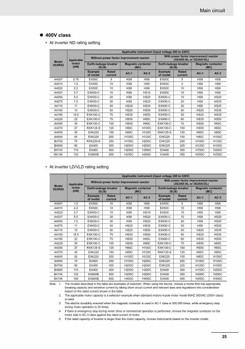
400V class
• At inverter ND rating setting
• At inverter LD/VLD rating setting
Note 1. The models described in the table are examples of selection. When using the device, choose a model that has appropriate breaking capacity and sensitive current by taking short circuit current and relevant laws and regulations into consideration based on the rated current shown in the table.
2. The applicable motor capacity is a selection example when standard motors 4-pole motor model 60HZ 200VAC (200V class) is used.
3. The electric durability ensured when the magnetic contactor is used in AC-1 class is 500,000 times, while emergency stop during motor operation is 25 times.
4. If there is emergency stop during motor drive or commercial operation is performed, choose the magnetic contactor on the motor side in AC-3 class against the rated current of motor.
5. If the rated capacity of inverter is larger than the motor capacity, choose instruments based on the inverter model.
Model3G3RX2
Applicable motor (kW)
Applicable instrument (input voltage 200 to 220V)
Without power factor improvement reactor With power factor improvement reactor
(3G3AX-AL or 3G3AX-DL)
Earth-leakage breaker (ELB)
Magnetic contactor (MC)
Earth-leakage breaker (ELB)
Magnetic contactor (MC)
Example of model
Rated current
AC-1 AC-3Example of model
Rated current
AC-1 AC-3
A4007 0.75 EX50C 5 HS8 HS8 EX50C 5 HS8 HS8
A4015 1.5 EX50C 10 HS8 HS8 EX50C 5 HS8 HS8
A4022 2.2 EX50C 10 HS8 HS8 EX50C 10 HS8 HS8
A4037 3.7 EXK50-C 15 HS8 HS10 EX50C 10 HS8 HS8
A4055 5.5 EXK50-C 20 HS8 HS20 EXK50-C 15 HS8 HS20
A4075 7.5 EXK50-C 30 HS8 HS25 EXK50-C 20 HS8 HS20
A4110 11 EXK50-C 40 HS20 HS35 EXK50-C 30 HS8 HS25
A4150 15 EXK50-C 50 HS25 HS50 EXK50-C 40 HS20 HS35
A4185 18.5 EXK100-C 75 HS35 HS50 EXK50-C 50 HS20 HS35
A4220 22 EXK100-C 75 HS50 H65C EXK60-C 60 HS35 HS50
A4300 30 EXK100-C 100 HS50 H80C EXK100-C 75 HS50 H65C
A4370 37 RXK125-S 125 H80C H100C EXK100-C 100 HS50 H65C
A4450 45 EXK225 150 H80C H125C RXK125-S 125 H65C H80C
A4550 55 EXK225 200 H100C H125C EXK225 150 H80C H100C
B4750 75 RXK250-S 250 H150C H200C EXK225 200 H100C H125C
B4900 90 EX400 300 H200C H250C EXK225 225 H125C H150C
B411K 110 EX400 400 H200C H300C EX400 300 H150C H250C
B413K 132 EX600B 500 H250C H300C EX400 350 H200C H250C
Model3G3RX2
Applicable motor (kW)
Applicable instrument (input voltage 200 to 220V)
Without power factor improvement reactor With power factor improvement reactor
(3G3AX-AL or 3G3AX-DL)
Earth-leakage breaker (ELB)
Magnetic contactor (MC)
Earth-leakage breaker (ELB)
Magnetic contactor (MC)
Example of model
Rated current
AC-1 AC-3Example of model
Rated current
AC-1 AC-3
A4007 1.5 EX50C 10 HS8 HS8 EX50C 5 HS8 HS8
A4015 2.2 EX50C 10 HS8 HS8 EX50C 10 HS8 HS8
A4022 3.7 EXK50-C 15 HS8 HS10 EX50C 10 HS8 HS8
A4037 5.5 EXK50-C 20 HS8 HS20 EXK50-C 15 HS8 HS20
A4055 7.5 EXK50-C 30 HS8 HS25 EXK50-C 20 HS8 HS20
A4075 11 EXK50-C 40 HS20 HS35 EXK50-C 30 HS8 HS25
A4110 15 EXK50-C 50 HS25 HS50 EXK50-C 40 HS20 HS35
A4150 18.5 EXK100-C 75 HS35 HS50 EXK50-C 50 HS20 HS35
A4185 22 EXK100-C 75 HS50 H65C EXK60-C 60 HS35 HS50
A4220 30 EXK100-C 100 HS50 H80C EXK100-C 75 HS50 H65C
A4300 37 RXK125-S 125 H80C H100C EXK100-C 100 HS50 H65C
A4370 45 EXK225 150 H80C H125C RXK125-S 125 H65C H80C
A4450 55 EXK225 200 H100C H125C EXK225 150 H80C H100C
A4550 75 EX400 250 H150C H200C EXK225 200 H100C H125C
B4750 90 EX400 300 H200C H250C EXK225 225 H125C H150C
B4900 110 EX400 400 H200C H300C EX400 300 H150C H250C
B411K 132 EX600B 500 H250C H300C EX400 350 H200C H250C
B413K 160 EX600B 600 H400C H400C EX400 400 H250C H300C

Control circuit
26
Control circuit
Outline of control circuit
Control circuit terminal areaBackup
24V power supplyterminal
P+
P-
1/RS
2/SCHG
3/JG
4/FRS
5/2CH
6/CF1
7/CF2
8/RV
9/FW
A/EXT
B/USP
COM
CM1
Interface24V power supply terminal
P24
HAi1
Ai2
Ai3
L
(+)
( - )
(± 10V)(0V)
TH+
AL2
AL1
AL0
16A
16C
11/RUN
12/FA1
13/FA2
14/ IRDY
15/OL
CM2
FM
CM1
Ao1
Ao2L
SPSN
SPSN
RP
P24S
STC
CMS
ST1
ST2
ED+
ED-
TH-
LL
10V
10V
20mA
10V
10V20mA
20mA
Voltage input
Current input
Voltage input
Current input
Input terminal
Thermistor
STO inputSTO confirmation output
Analoginput 3
Analoginput 2
Analoginput 1
P24
CM1
DC24V
P24
CM1
P24
IN
EXSource
Sink(SW5)
(SW6)
(SW1)
(SW2)
(SW3)
(SW4)
16/ZS
Operation section
USB RJ45
PC (ProDriveNext) LCD operator
20mA
You can switch between the sink logic and source logic for input terminals by using SW6.
* The signal ground for RS485 terminal is CM1
RS485 terminalModbus communication
Output terminals* Supporting sink/source
Relay 1A contact
Alarm relay 1C contact

27
Control circuit
Input terminals• All COM terminals are at the same potential.
• When connecting a power supply between 1-9, A, B and COM, switch SW5 to the external power supply (EX).
• You can switch between the sink/source logic of input terminals by using SW6.
(Wiring example)
• Indicates the factory default setting.
Terminal symbol
Terminal name
Description Electrical characteristics
Input terminal
Digital input
Contact9, 8, 7, 6, 5, 4, 3, 2, 1
Input terminal
You can select terminal functions using the parameter settings corre-sponding to each terminal. You can switch between the sink logic and source logic by switching SINK/SRC of SW6.
Voltage between each input/COM
• ON voltage Min. DC18V
• OFF voltage Max. DC3V
• Maximum allowable voltage DC27V
• Load current 5.6mA (at DC27V)
Contact/pulse
APulse input-A
This is a terminal for pulse input. A and B terminals can be used also as an input terminal.
Terminal functions are selectable according to the parameter settings for each terminal.
The maximum input pulse rate is 32kpps.
Voltage between each input/COM
• ON voltage Min. DC18V
• OFF voltage Max. DC3V
• Maximum allowable voltage DC27V
• Load current 5.6mA (at DC27V)
• Maximum 32kpps pulse input
BPulse input-B
Common COMCommon for input terminal
Common terminals for digital input ter-minals (1, 2, 3, 4, 5, 6, 7, 8, 9, A, B). There are three COM terminals.
input
1 [RS]
2 [SCHG]
3 [JG]
4 [FRS]
5 [2CH]
6 [CF1]
7 [CF2]
8 [RV]
9 [FW]
A [EXT]
B [USP]
COMCOMCOM
Control circuit terminal area SW6SW5

Control circuit
28
Initial terminal functionThis section describes the function of the initial shipment value. Please check the detailed function in the user's manual (I620-E1).
[RS:028] Reset• Reset at every trip.
[SCHG:015] Command source change• Change to the main speed command
[AA101](OFF) or sub-speed command
[AA102](ON).
[JG:029] Jogging• Run at a frequency of [AG-20] upon receipt of
the operation command by [JG]ON.
[FRS:032] Free-run stop• [FRS] ON sets the motor in a free-run state.
[2CH:031] Two-step acceleration/deceleration• [2CH]ON enables acceleration/deceleration
time-2 [AC124][AC126].
[EXT:033] External trip• [EXT] ON issues Trip [E012].
[FW:001] Forward rotation and [RV:002] Reverse rotation
[CF1:003] Multispeed-1 and [CF2:004] Multi-speed-2 commands
[USP:034] Unattended start protection• In a [USP] ON state, if an operation command
has been input before the power supply is ON,
Trip [E013] is issued.
Forward Reverse Description
OFF OFF No command
ON OFF Forward rotation command operation
OFF ON Reverse rotation command operation
ON ON No command (inconsistent logic)
* Setting CF3 and 4 allows you to set up to 16-speed.
Multi-speed-1
CF1
Multi-speed-2
CF2Description
OFF OFF The set frequency source is enabled.
ON OFF The frequency source of [Ab-11] is enabled.
OFF ON The frequency source of [Ab-12] is enabled.
ON ON The frequency source of [Ab-13] is enabled.

29
Control circuit
Output terminals (Wiring example)
Terminal symbol
Terminal name
Description Electrical characteristics
Output terminal
Digital output
Open collector
15, 14
13, 12
11
Output terminal
You can select terminal functions using the parameter settings corre-sponding to each terminal.
These terminals can be used both in sink logic or source logic.
Open collector output
• Between each terminal and CM2
• Voltage drop at ON: 4V or below
• Maximum allowable voltage: 27V
• Maximum allowable current: 50mA
CM2 Common for output terminal
Common terminals for output termi-nals 11-15
Relay
16A
16C
1a relay terminal
A relay for contact A output. Maximum capacity of contact
• AC250V, 2A (resistance)
• AC250V, 1A (induction)
Minimum capacity of contact
• DC1V, 1mA
AL0
AL1
AL2
1c relay terminal
A relay for contact C output. Maximum capacity of contact
AL1/AL0:
• AC250V, 2A (resistance)
• AC250V, 0.2A (induction)
AL2/AL0:
• AC250V, 1A (resistance)
• AC250V, 0.2A (induction)
Minimum capacity of contact (com-mon)
• AC100V, 10mA
• DC5V, 100mA

Control circuit
30
Initial terminal functionThis section describes the function of the initial shipment value. Please check the detailed function in the user's manual (I620-E1).
[RUN:001] During operation signal• Turns ON during operation (PWM output).
About [AL] operation• When [CC-17] = 00
• When [CC-17] = 01
[FA1:002] Frequency reached signal• Turns ON when the output frequency reaches
the command frequency.
[FA2:003] Frequency reached signal 2• Turns ON when the output frequency reaches
the set frequency [CE-10]-[CE-13].
[IRDY:007] Operation ready completion• Turns ON when operation is ready.
[OL:035] Overload advance notice• Turns ON when current exceeds the level of
overload advance notice.
[ZS:040] 0 Hz detection signal• Turns ON when the output frequency goes
below the 0-Hz detection value level [CE-33].
Power supply
Status AL0-AL1 AL0-AL2
ON Normal Open Close
ON Trip Close Open
OFF --- Open Close
Power supply
Status AL0-AL1 AL0-AL2
ON Normal Close Open
ON Trip Open Close
OFF --- Open Close

31
Control circuit
Analog input/output (Wiring example)
Terminal symbol
Terminal name Description Electrical characteristics
Analog input terminal for switching voltage and current
Power supply
L Analog
power common
Common terminals for analog input terminals (Ai1, Ai2, Ai3) and analog output terminals (Ao1, Ao2). There are two L terminals.
H Power supply for setting speed
This is a DC10V power supply. It is used when using analog input termi-nals (Ai1, Ai2, Ai3) and variable resistor for inputting voltage.
Maximum allowable input current 20mA
Analog input
Ai1 Analog input terminal 1 (voltage/current switching SW1)
For Ai1 and Ai2, DC0-10V voltage input and 0-20mA current input can be switched using a switch for use. It can be used for input frequency command or feedback.
In the case of voltage input:
• Input impedance about 10kΩ
• Allowable input voltage DC-0.3V to 12V
In the case of current input:
• Input impedance about 100Ω
• Maximum allowable input current 24mA
Ai2 Analog input terminal 2 (voltage/current switching SW2)
Ai3 Analog input terminal 3
-10V to 10V voltage input is avail-able. It can be used for input fre-quency command or feedback.
Only voltage input:
• Input impedance about 10kΩ
• Allowable voltage input -12V to 12V
Analog output
Ao1 Analog output terminal 1 (voltage/current switching SW3)
For Ao1 and Ao2, DC0-10V voltage output and 0-20mA current output can be switched using a switch as output of information monitor data of the inverter.
In the case of voltage output:
• Maximum allowable output current 2mA
• Output voltage accuracy ±10% (ambient temperature: 25°C±10°C)
In the case of current input:
• Allowable load impedance 250Ω or below
• Output current accuracy: ±20% (ambient temperature: 25°C±10°C)
Ao2 Analog output terminal 2 (voltage/current switching SW4)

Control circuit
32
External thermistor (Wiring example)
Terminal symbol
Terminal name
Description Electrical characteristics
Thermistor terminal
Analog input
TH+
External thermistor input
Connect to an external thermistor to make the inverter trip if an abnormal temperature is detected.
Connect the thermistor to TH+ and TH-. The impedance to detect temperature errors can be adjusted within the range 0Ω to 10,000Ω.
[Recommended thermistor properties]Allowable rated power: 100 mW or more Impedance at temperature error: 3kΩ
DC 0 to 5V
[Input circuit]
TH-
Common for external thermistor
TH-TH+
External thermistor terminals
Thermistor
Control circuit terminal
• Twist the cables connected from a thermistor to the TH terminal only between TH+ and TH-, and separate the twisted cables from other cables.
• Since very low current flows through the cables connected to the thermistor, separate the cables from those (power line cables) connected to the main circuit.
• The length of the cables connected to the thermistor must be 20 m or less.
DC5V 1kΩ
2kΩ TH-
TH+ Thermistor

33
Control circuit
Description of switches
Indication SW name Description
Ai1 (SW1)
Analog input 1 switch
Switches input specification of analog input 1 (Ai1 terminal).
10V: Voltage input is available.
20mA: Current input is available.
Ai2 (SW2)
Analog input 2 switch
Switches input specification of analog input 2 (Ai2 terminal).
10V: Voltage input is available.
20mA: Current input is available.
Ao1 (SW3)
Analog output 1 switch
Switches output specification of analog output 1 (Ao1 terminal).
10V: Output changes to voltage output.
20mA: Output changes to current output.
Ao2 (SW4)
Analog output 2 switch
Switches output specification of analog output 2 (Ao2 terminal).
10V: Output changes to voltage output.
20mA: Output changes to current output.
P.SEL (SW5)
Switching the method of power supply to the input
terminals
Switches the method of power supply to the input terminals.
IN: Drives the input terminals using the internal power supply.
EX: Use an external power supply to drive input terminals. (In the case of EX, a power supply is required between the input terminals and COM.)
SRC/SINK (SW6)
Switch of sink/source for the input terminals
Switches the sink/source logic for input terminals.
This switch is enabled when SW5 is IN.
SINK: Enables sink logic.
SRC: Enables source logic.
Control circuit terminal area
SW
4
SW
3
SW
2
SW
1
SW
5
SW
6
10V
20mA
10V
20mA
10V
20mA
10V
20mA
IN
EX
SINK
SRCAo2 Ao1 Ai2 Ai1 P.SE
(SW4) (SW3) (SW2) (SW1) (SW5) (SW6)(SW4) (SW3) (SW2) (SW1) (SW5) (SW6)
* Using a switch under power-on condition may cause failure. Use the switch only after turning off the power and confirming that the POWER lamp on the operator keypad is off.
(Factory setting)

Control circuit
34
RS485 Communication Terminal
SP and SN terminals with the same names are internally connected respectively, so they can be used for wiring multiple terminals.
Terminal symbol
Terminal name
DescriptionElectrical character-
istics
RS485 com-munication
Serial communi-
cation
SPSNRP
(CM1)
RS-485 terminal
for Modbuscommuni-
cation
SP terminal: RS-485 differential (+) signal
SN terminal: RS-485 differential (-) signal
RP terminal: Connect to SP via tile terminating resistor
CM1 terminal: Connect with the signal ground of an external communication device. (also used by FM terminal)
There are two SP terminals and SN terminals each, which are connected internally.Maximum baud rate is 115.2kbps.
Equipped with termi-nating resistor
(120Ω)
Enable: Short RP-SN
Disable: Open RP-SN
(+) (-)
Control circuit terminal area
Modbus communication
RPSNSPSNSPCM1
Connect CM1 to the SG (signal ground) of an external device.
When enabling the terminating resistor, short RP-SN.
35
Control circuit
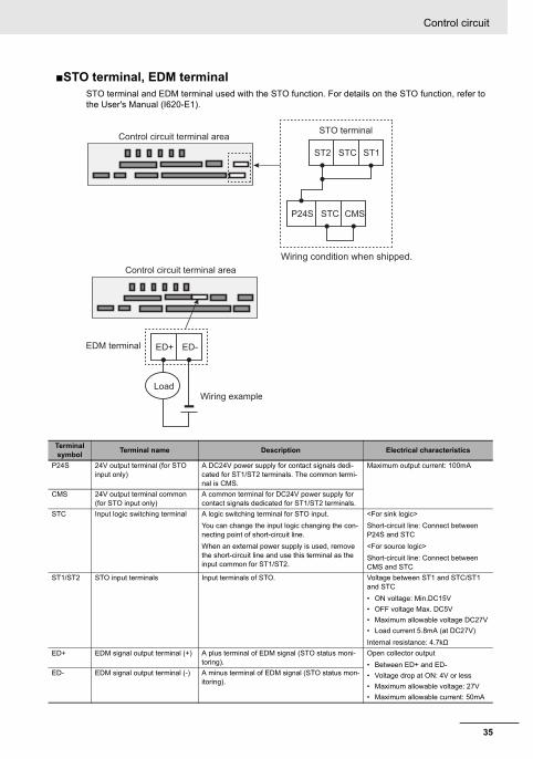
STO terminal, EDM terminalSTO terminal and EDM terminal used with the STO function. For details on the STO function, refer to the User's Manual (I620-E1).
Terminal symbol
Terminal name Description Electrical characteristics
P24S 24V output terminal (for STO input only)
A DC24V power supply for contact signals dedi-cated for ST1/ST2 terminals. The common termi-nal is CMS.
Maximum output current: 100mA
CMS 24V output terminal common (for STO input only)
A common terminal for DC24V power supply for contact signals dedicated for ST1/ST2 terminals.
STC Input logic switching terminal A logic switching terminal for STO input.
You can change the input logic changing the con-necting point of short-circuit line.
When an external power supply is used, remove the short-circuit line and use this terminal as the input common for ST1/ST2.
<For sink logic>
Short-circuit line: Connect between P24S and STC
<For source logic>
Short-circuit line: Connect between CMS and STC
ST1/ST2 STO input terminals Input terminals of STO. Voltage between ST1 and STC/ST1 and STC
• ON voltage: Min.DC15V
• OFF voltage Max. DC5V
• Maximum allowable voltage DC27V
• Load current 5.8mA (at DC27V)
Internal resistance: 4.7kΩ
ED+ EDM signal output terminal (+) A plus terminal of EDM signal (STO status moni-toring).
Open collector output
• Between ED+ and ED-
• Voltage drop at ON: 4V or less
• Maximum allowable voltage: 27V
• Maximum allowable current: 50mA
ED- EDM signal output terminal (-) A minus terminal of EDM signal (STO status mon-itoring).
Control circuit terminal area
Wiring condition when shipped.
STO terminal
ST2 STC ST1
P24S STC CMS
Control circuit terminal area
EDM terminal
Wiring example
ED+ ED-
Load

Control circuit
36
Recommended Terminal for wiring• For the convenience of wiring and improvement of connection reliability, it is recommended to use
rod terminals with the following specifications.
• For the control circuit terminal block, spring type terminal blocks are mounted.
Rod terminal with Sleeve
* Manufacturer: Phoenix Contact.Caulking tool CRIMPFOX UD 6-4 or CRIMPFOX ZA 3
Method of wiring/detaching wires
1 Press in the orange portion on the control circuit terminal block using a slotted screwdriver (2.5mm or less in width).
(The wire insertion slot opens.)
2 While pressing the slotted screwdriver in the terminal block, insert the wire or rod terminal into the wire insertion slot (round hole).
3 Extract the slotted driver to fix the wire.
Also when extracting the wire, extract it while the orange portion is pressed in with the slotted screwdriver (the wire insertion slot is open).
Wire size
mm2 (AWG)Rod terminal model * L1 [mm] L2 [mm] φd [mm] φD [mm]
0.25 (24) AI 0,25-8YE 8 12.5 0.8 2.0
0.34 (22) AI 0,34-8TQ 8 12.5 0.8 2.0
0.5 (20) AI 0,5-8WH 8 14 1.1 2.5
0.75 (18) AI 0,75-8GY 8 14 1.3 2.8
φd
φD
L1L2
2.5 mm
Press in the orange portion using a slotted screwdriver
Insert the wire Extract the slotted driver to fix the wire

37
Conditions of conformity of EU directives
Conditions of conformity of EU directives
Specifications
• This is a product designed for industrial environments.Use in residential area may cause radio interference, in which case the user may be required to take adequate measures to reduce interferense.
• This type of PDS is not intended to be used on a low-voltage public network which supplies domestic premises.
Manufacturer and EU RepresentativeManufacturer: OMRON Corporation
Shiokoji Horikawa, Shimogyo-ku, Kyoto, 600-8530 Japan
Representative and Importer in EU: OMRON EUROPE B.V. Wegalaan 67-69,2132 JD Hoofddorp, The Netherlands
GENERAL:
3G3RX2 series Type inverter is open type AC Inverter with three phase input and three phase output. It is intended to be used in an enclosure. It is used to provide both an adjustable voltage and adjustable frequency to the ac motor. The inverter automatically maintains the required volts-Hz ratio allowing the capability through the motor speed range. It is multi-rated device and the ratings are selectable accord-ing to load types by operator with key pad operation.
Compatibility Conditions of EMC DirectivesCAUTION for EMC
(Electromagnetic Compatibility)
3G3RX2 series inverter conforms to requirements of Electromagnetic Compatibility (EMC) Directive (2014/30/EU). However, when using the inverter in Europe, you must comply with the following specifi-cations and requirements to meet the EMC Directive and other standards in Europe:
1. Power supply requirements
a) Voltage fluctuation must be -15% to +10% or less.
b) Voltage imbalance must be ±3% or less.
c) Frequency variation must be ±4% or less.
d) Total harmonic distortion (THD) of voltage must be±10% or less.
2. Installation requirement
a) 3G3RX2 series includes a built-in EMC filter. The built-in EMC filter must be activated.
EMC EN61800-3:2004/AI:2012
Machinery IEC61800-5-2:2016
EN ISO 13849-1:2014
EN61800-5-1:2007
This equipment must be installed, adjusted, and maintained by qualified engineers who have expert knowledge of electric work, inverter operation, and the hazard ouscircumstances that can occur. Otherwise, personal injury may result.

Conditions of conformity of EU directives
38
b) According to EN61800-3 it is mandatory to mention that any inverter with only C3 filter inside may NOT be connected to a low voltage public power supply in residential areas since for these installations C1 is required.
c) In case of external filter for C2, an additional note is required according to EN61800-3 that “this product may emit high frequency interference in residential areas which may require additional EMC measures”.
d) According to the EN6100-3-12, an additional AC reactor or DC choke should be installed for reducing harmonics in power line.
3. Wiring requirements
a) A shielded wire (screened cable) must be used for motor wiring, and the length of the cable must be according to the following table.
b) The carrier frequency must be set according to the following table to meet an EMC requirement.
c) The main circuit wiring must be separated from the control circuit wiring.
4. Environmental requirements (to be met when a filter is used)
a) 3G3RX2 series inverter that is activated built-in EMC filter must be according to 3G3RX2 series specifications.
Table 1
Conditions of Electrical Safety (LVD)The condition in the next section UL standard explain the condition of the electrical safety. It is neces-sary to comply with the description items such as temperature condition, installation condition etc.
Model3G3RX2
Cat. Cable lengthCarrier
frequencyModel
3G3RX2Cat. Cable length
Carrier frequency
A2004 C3 10m 2kHz -- -- -- --
A2007 C3 10m 2kHz A4007 C3 10m 2kHz
A2015 C3 10m 2kHz A4015 C3 10m 2kHz
A2022 C3 10m 2kHz A4022 C3 10m 2kHz
A2037 C3 10m 2kHz A4037 C3 10m 2kHz
A2055 C3 5m 2kHz A4055 C3 5m 2kHz
A2075 C3 5m 2kHz A4075 C3 5m 2kHz
A2110 C3 5m 2kHz A4110 C3 5m 2kHz
A2150 C3 10m 1kHz A4150 C3 10m 2kHz
A2185 C3 10m 1kHz A4185 C3 10m 2kHz
A2220 C3 10m 1kHz A4220 C3 10m 2kHz
A2300 C3 5m 2kHz A4300 C3 5m 2kHz
A2370 C3 5m 2kHz A4370 C3 5m 2kHz
A2450 C3 5m 2kHz A4450 C3 5m 2kHz
A2550 C3 5m 2kHz A4550 C3 5m 2kHz
--- --- --- --- B4750 C3 3m 2kHz
--- --- --- --- B4900 C3 3m 2kHz
--- --- --- --- B411K C3 3m 2kHz
--- --- --- --- B413K C3 3m 2kHz

39
Compatibility Conditions of UL/CSA Standards
Compatibility Conditions of UL/CSA Standards
Standards
UL CAUTION
GENERAL:
Model 3G3RX2 series inverter is an open type AC Inverter with three phase input and three phase out-put. It is intended to be used in an enclosure. It is used to provide both an adjustable voltage and adjustable frequency to the ac motor. The inverter automatically maintains the required volts-Hz ratio allowing the capability through the motor speed range. It is a multi-rated device and the ratings are selectable according to load types by operator with key pad operation.
* For actual use, use within the temperature range indicated in the common specifications.
3G3RX2 series models Short circuit rating and overcurrent protection device rating:
• 3G3RX2-A2 series models
Suitable for use on a circuit capable of delivering not more than (a) rms symmetrical amperes, at (b) V maximum”. (see table below)
• 3G3RX2-A4 3G3RX2-B4 series models
Suitable for use on a circuit capable of delivering not more than (a) rms symmetrical amperes, at (b) V maximum”. (see table below)
Integral:
Integral solid state short circuit protection does not provide branch circuit protection. Branch circuit protection must be provided in accordance with the National Electrical Code and any additional local codes.
Integral solid state short circuit protection does not provide branch circuit protection. Branch circuit protection must be provided in accordance with the Canadian Electrical Code, part1" or the equiva-lent. (For Canada)
US UL61800-5-1
CA CSA 22.2 No.274
FS IEC61800-5-2:2016 STO SIL3ISO13849-1:2015 Cat.4 PLe
Markings:
Maximum Surrounding Temperature:
ND (Normal Duty): 50°C
LD (Low Duty): 50°C*
VLD (Very Low Duty): 45°C*
Storage Environment rating: 65°C (for transportation)
Instruction for installation: pollution degree 2 environment and Over voltage category III
Electrical Connections: See [Main circuit Wiring Diagram] of this Instruction Manual
Interconnection and wiring diagrams: See [Outline of control circuit] of this Instruction Manual
3G3RX2- (a) (b)
200V A2004 to A2220 5,000A rms 240V
A2300 to A2550 10,000A rms 240V
400V A4007 to A4220 5,000A rms 500V
A4300 to A4550,B4750, B4900 10,000A rms 500V
B411K, B413K 18,000A rms 500V

Compatibility Conditions of UL/CSA Standards
40
Field wiring terminal conductor size and Torque Values making for field wiring terminal
Note 1. Temperature rating of field wiring installed conductors is 75°C only.
2. Use Copper conductors only.
Model3G3RX2
Load Type
Required Torque (N·m)Conductorsize (AWG)
Model3G3RX2
Load Type
Required Torque (N·m)Conductorsize (AWG)
A2004VLD
1.4 14LDND
A2007 VLD
1.4 14 A4007VLD
1.4 14LD LDND ND
A2015VLD
1.4 14 A4015VLD
1.4 14LD LDND ND
A2022VLD
1.4 10 A4022VLD
1.4 14LD LDND ND
A2037VLD
1.4 10 A4037VLD
1.412
LD LD14
ND ND
A2055VLD
3 8 A4055VLD
310
LD LD12
ND ND
A2075VLD
36
A4075VLD
38
LD8
LD10
ND ND
A2110VLD
44
A4110VLD
4 8LD LDND 6 ND
A2150VLD
2.5 to 3.03
A4150VLD
4 8LD LDND 4 ND
A2185VLD
2.5 to 3.01
A4185VLD
46
LD 2 LDND 3 ND 8
A2220VLD
5.5 to 6.62/0
A4220VLD
44
LD 1/0 LDND 1 ND 6
A2300VLD
6Parallel of 1/0
A4300VLD
61
LD LD 2ND 2/0 ND 3
A2370VLD
6 to 10Parallel of 1/0
A4370VLD
15 1LD Parallel of 1/0 LDND 15 4/0 ND
A2450VLD
6 to 10Parallel of 2/0
A4450VLD
151/0
LD Parallel of 1/0 LDND Parallel of 1/0 ND 1
A2550VLD
10 to 12Parallel of 3/0
A4550VLD 6 to 10 Parallel of 1/0
LD Parallel of 3/0 LD15
2/0ND 350kcmil ND 1/0
B4750VLD
10 to 12 Parallel of 1/0LDND
B4900VLD
10 to 12Parallel of 2/0
LDParallel of 1/0
ND
B411KVLD
10 to 12Parallel of 3/0
LDParallel of 2/0
ND
B413KVLD
10 to 12P. of 250kxmil
LD Parallel of 4/0ND Parallel of 3/0
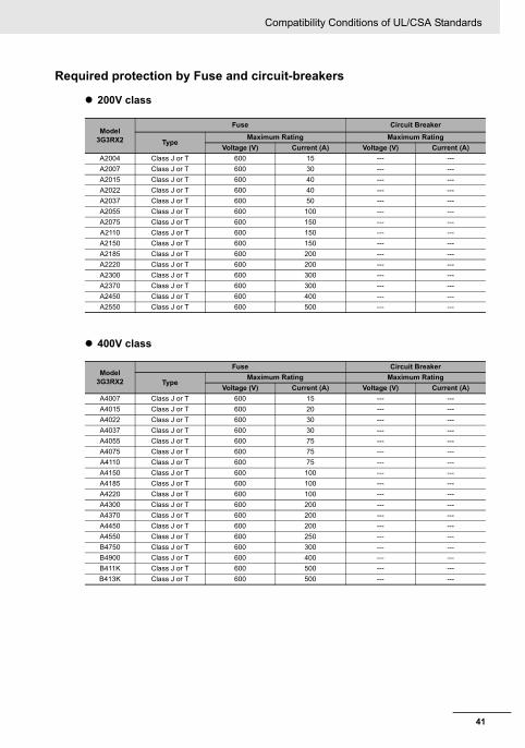
41
Compatibility Conditions of UL/CSA Standards
Required protection by Fuse and circuit-breakers
200V class
400V class
Model3G3RX2
Fuse Circuit Breaker
TypeMaximum Rating Maximum Rating
Voltage (V) Current (A) Voltage (V) Current (A)
A2004 Class J or T 600 15 --- ---
A2007 Class J or T 600 30 --- ---
A2015 Class J or T 600 40 --- ---
A2022 Class J or T 600 40 --- ---
A2037 Class J or T 600 50 --- ---
A2055 Class J or T 600 100 --- ---
A2075 Class J or T 600 150 --- ---
A2110 Class J or T 600 150 --- ---
A2150 Class J or T 600 150 --- ---
A2185 Class J or T 600 200 --- ---
A2220 Class J or T 600 200 --- ---
A2300 Class J or T 600 300 --- ---
A2370 Class J or T 600 300 --- ---
A2450 Class J or T 600 400 --- ---
A2550 Class J or T 600 500 --- ---
Model3G3RX2
Fuse Circuit Breaker
TypeMaximum Rating Maximum Rating
Voltage (V) Current (A) Voltage (V) Current (A)
A4007 Class J or T 600 15 --- ---
A4015 Class J or T 600 20 --- ---
A4022 Class J or T 600 30 --- ---
A4037 Class J or T 600 30 --- ---
A4055 Class J or T 600 75 --- ---
A4075 Class J or T 600 75 --- ---
A4110 Class J or T 600 75 --- ---
A4150 Class J or T 600 100 --- ---
A4185 Class J or T 600 100 --- ---
A4220 Class J or T 600 100 --- ---
A4300 Class J or T 600 200 --- ---
A4370 Class J or T 600 200 --- ---
A4450 Class J or T 600 200 --- ---
A4550 Class J or T 600 250 --- ---
B4750 Class J or T 600 300 --- ---
B4900 Class J or T 600 400 --- ---
B411K Class J or T 600 500 --- ---
B413K Class J or T 600 500 --- ---

Korean Radio Regulation (KC)
42
Korean Radio Regulation (KC)
Guide for Users
This equipment has been evaluated for conformity in a commercial environment.
When used in a residential environment, it may cause radio interference.


![NA-series HMI [Programmable Termina]l Device Connection ... Documents/Omron... · nation with any electrical or electronic components, circuits, system assemblies or any other materi-als](https://static.fdocuments.in/doc/165x107/5d151dd388c993152a8c02a7/na-series-hmi-programmable-terminal-device-connection-documentsomron.jpg)


