Instruction Manual Model CA-6 Analyzer Aluminum Aluminum...ELECTRO-CHEMICAL DEVICES Instruction...
78
ELECTRO-CHEMICAL DEVICES Instruction Manual Model CA-6 Analyzer Aluminum The information and technical data disclosed in this document may be used and disseminated only for the purposes and to the extent specifically authorized in writing by Electro-Chemical Devices. Electro-Chemical Devices reserves the right to change published specifications and designs without prior notice. Part No. IM CA6 Al Rev: B– 03/13
-
Upload
nguyenkhanh -
Category
Documents
-
view
230 -
download
2
Transcript of Instruction Manual Model CA-6 Analyzer Aluminum Aluminum...ELECTRO-CHEMICAL DEVICES Instruction...

ELECTRO-CHEMICAL DEVICES
Instruction Manual Model CA-6 Analyzer
Aluminum
The information and technical data disclosed in this document may be used and disseminated only for the purposes and to the extent specifically authorized in writing by Electro-Chemical Devices. Electro-Chemical Devices reserves the right to change published specifications and designs without prior notice. Part No. IM CA6 Al
Rev: B– 03/13

PREFACE Purchasing products from Electro-Chemical Devices, Inc. provides you with the finest liquid analytical instrumentation available. If this is your first purchase from ECD, please read this manual before installing and commissioning your new equipment.
If there are any questions concerning this equipment, please contact your local ECD representative, or the factory directly at:
Electro-Chemical Devices, Inc. 1681 Kettering
Irvine, CA 92887 USA Telephone: +1-949-336-6060
FAX: +1-949-336-6064 Website: www.ecdi.com Email: [email protected]
© 2013 Electro-Chemical Devices, Inc. All rights reserved. No part of this manual may be used or reproduced in any form or by any means, or stored in a database or retrieval system without prior written permission from Electro-Chemical Devices, Inc. Making copies of any part of this manual for any purpose other than personal use is a violation of United States copyright laws. Document printed in the United States of America.
CA-6 Analyzers Page ii

TABLE OF CONTENTS PREFACE ........................................................................................................................................................ ii
TABLE OF CONTENTS .................................................................................................................................... iii
WARRANTY ................................................................................................................................................. vii
IMPORTANT SERVICE INFORMATION ......................................................................................................... vii
UNPACKING THE INSTRUMENT.................................................................................................................. viii
1.0 OVERVIEW ............................................................................................................................................... 1
CONTENTS: ................................................................................................................................................ 1
1.0.1 CA-6 Technical Specifications ....................................................................................................... 2
1.1 Safety Precautions, Instructions and Hazards .................................................................................... 3
1.1.1 General information ..................................................................................................................... 3
1.1.2 List of warnings and potential dangers ........................................................................................ 3
1.1.3 Reagents ....................................................................................................................................... 4
1.1.4 Sample Stream ............................................................................................................................. 5
1.1.5 Waste disposal of the liquid reagents for the colorimetric reaction ........................................... 5
1.1.6 Analyzer General Hazards ............................................................................................................ 5
2.0 INTRODUCTION – Analyzer Description .................................................................................................. 7
2.1 Applications ......................................................................................................................................... 7
2.2 Working principle: Lambert-Beer law ................................................................................................. 7
2.2.1 Absorption photometry (Colorimetry): ........................................................................................ 8
2.3 Analysis Cycle ...................................................................................................................................... 9
2.3.1 Typical Run Sequence: ................................................................................................................. 9
2.3.2 Settings ....................................................................................................................................... 10
2.3.3 Programmable Functions ........................................................................................................... 11
2.4 Components ...................................................................................................................................... 15
2.4.1 Fast-loop reservoir ..................................................................................................................... 15
2.4.2 Sampling Pump .......................................................................................................................... 16
2.4.3 3 Way Valve ................................................................................................................................ 16
2.4.4 Micro Peristaltic Pumps ............................................................................................................. 16
2.4.5 Mixing Pump .............................................................................................................................. 16
2.4.6 Pinch Valve ................................................................................................................................. 16
CA-6 Analyzers Page iii

2.4.7 Colorimetric Reaction Cell .......................................................................................................... 17
2.4.8 Sample Drain .............................................................................................................................. 17
2.4.9 Electronic Components .............................................................................................................. 17
3.0 OPTIONS ................................................................................................................................................ 18
3.1 Dilution Module ................................................................................................................................ 18
3.2 Oxidation/Digestion Module ............................................................................................................. 19
4.0 INSTALLATION ........................................................................................................................................ 21
4.1 Unpacking and Inspecting ................................................................................................................. 21
4.2 Analyzer Handling ............................................................................................................................. 21
4.3 Location and Mounting Instructions ................................................................................................. 21
4.4 Pre-Installation .................................................................................................................................. 21
4.5 Electrical Connections ....................................................................................................................... 22
4.5.1 General information ................................................................................................................... 22
4.5.2 AC Power Connections ............................................................................................................... 23
4.5.3 Signal Output Connections – TB (4-20 mA, alarm, aux, RS232) ................................................. 23
5.0 REAGENTS PREPARATION ..................................................................................................................... 24
5.1 Method of Analysis ........................................................................................................................... 24
6.0 ANALYZER INITIAL START-UP ................................................................................................................. 25
6.1 Sample and Drain Tubing Connections ............................................................................................. 25
6.2 Powering, Priming and Starting the Analyzer ................................................................................... 26
7.0 CALIBRATION ......................................................................................................................................... 28
7.1 Blank Calibration (Zero Point) ........................................................................................................... 28
7.2 Slope Calibration (Factor) ................................................................................................................. 29
7.3 Step by Step Manual Calibration ...................................................................................................... 29
8.0 USER INTERFACE ................................................................................................................................... 31
8.1 Touch Screen Display ........................................................................................................................ 31
8.2 Passwords (****) .............................................................................................................................. 31
8.3 Main Screen .................................................................................................................................... 32
8.3.1 Status Modes ............................................................................................................................. 33
8.3.2 Menu Buttons ............................................................................................................................ 33
8.4 RUN MENU ........................................................................................................................................ 34
8.4.1 START ON-LINE? ......................................................................................................................... 34
CA-6 Analyzers Page iv
8.4.2 CYCLE Ch1 / CYCLE Ch2 / Cycle Extra ......................................................................................... 34
8.4.3 EMERGENCY STOP ...................................................................................................................... 34
8.5 DISPLAY MENU .................................................................................................................................. 35
8.5.1 Display Process Values ............................................................................................................... 35
8.5.2 Chart ........................................................................................................................................... 35
8.5.3 Manual Step ............................................................................................................................... 35
8.6 PROGRAM MENU .............................................................................................................................. 36
8.6.1 Analysis Cycle ............................................................................................................................. 36
8.6.2 Extra Cycle .................................................................................................................................. 37
8.6.3 Settings Menu ............................................................................................................................ 37
8.6.2 Calibration Menu ....................................................................................................................... 37
8.7 SERVICE MENU .................................................................................................................................. 38
8.7.1 Method of Operation ................................................................................................................. 39
8.8 ? HELP MENU ................................................................................................................................... 40
8.8.1 Analyzer Installation................................................................................................................... 41
8.8.2 Analyzer Start Up ....................................................................................................................... 44
8.8.3 Start/Stop Commands ................................................................................................................ 46
8.8.4 Calibrations ................................................................................................................................ 47
8.8.5 Program / Modify Cycles ............................................................................................................ 49
8.8.6 Functions List ............................................................................................................................. 50
8.8.7 Shut Down Procedure ................................................................................................................ 54
8.8.8 Maintenance .............................................................................................................................. 55
8.8.9 Troubleshooting ......................................................................................................................... 56
9.0 MAINTENANCE ...................................................................................................................................... 57
9.0.1 Visual check ................................................................................................................................ 57
9.0.2 Monthly ...................................................................................................................................... 57
9.0.3 Every 4-6 months ....................................................................................................................... 58
9.0.4 Annual ........................................................................................................................................ 58
9.1 Sample Pump tubing replacement ................................................................................................... 58
9.2 Micro Peristaltic Tubing Replacement .............................................................................................. 59
9.3 Accessories and Spare Parts ............................................................................................................. 60
10.0 ANALYZER SHUT DOWN ...................................................................................................................... 62
CA-6 Analyzers Page v

11.0 REAGENT RECIPE and PROGRAM SEQUENCE ..................................................................................... 63
11.1 Analysis Cycle .................................................................................................................................. 64
11.2 Extra Cycle ....................................................................................................................................... 65
11.3 TEST DATA ....................................................................................................................................... 66
11.4 Reagents .......................................................................................................................................... 67
11.4.1 REAGENT 1 ............................................................................................................................... 67
11.4.2 REAGENT 2 ............................................................................................................................... 68
11.4.3 Standard Solution, 500 ppm Al ................................................................................................ 68
CA-6 Analyzers Page vi

WARRANTY Electro-Chemical Devices, Inc. (ECD) warrants all products it manufactures to be free from defect in materials and factory workmanship, and agrees to repair or replace any product that fails to perform, as specified, within one (1) year after date of shipment. This warranty shall not apply to any product that has been:
1. Subjected to misuse, negligence or accident; 2. Connected, installed, adjusted or otherwise used not in accordance with the instructions furnished by ECD; 3. Repaired, modified or altered by persons not authorized by ECD, resulting in injury to the performance, stability or
reliability of the product.
This warranty is in lieu of any other warranty, expressed or implied. ECD reserves the right to make changes in the design or construction of its products at any time, without prior notification, and without incurring any obligation to make any changes in previously delivered products.
Seller’s sole liabilities and the buyer’s sole remedies under this agreement shall be limited to a refund in the purchase price, or at ECD’s discretion, to the repair or replacement of any product that proves, upon ECD’s examination, to be defective, when returned to the factory, transportation prepaid by the buyer, within one (1) year of the product’s original shipment date. Seller shall not be liable for damages consequential or incidental to defects in any product, for failure of delivery in whole or in part, for injuries resulting from its use, or for any other cause.
This warranty and the writing attached constitute the full understanding of seller and the buyer, and no terms, conditions, understanding, or agreement purporting to modify or vary the terms hereof shall be binding unless hereafter made in writing and signed by an authorized official of Electro-Chemical Devices, Inc.
This warranty does not cover pH, ORP or Specific Ion measurement, reference or combination electrodes or electrode cartridges that have been commissioned in service.
IMPORTANT SERVICE INFORMATION Use only factory authorized components for repair. Tampering or unauthorized substitution of components may adversely affect the operation of this product and may void the warranty.
If service or repair is required, please obtain the serial number(s) or sales order number of the product(s) in question and contact ECD’s Service Department at:
+1-800-729-1333 (USA/Canada) or +1-949-336-6060 or email [email protected]
A Return Material Authorization (RMA) number must be obtained from the service department before returning any material to ECD. All material returned to ECD shall be shipped prepaid to the factory.
CA-6 Analyzers Page vii
UNPACKING THE INSTRUMENT Your Electro-Chemical Devices instrument has been carefully packaged to protect it from damage during shipment and dry storage. Upon receipt please follow the procedure outlined below.
1. Before unpacking, inspect the condition of the shipping container to verify proper handling by the carrier. If damage is noted, save the shipping container as proof of mishandling for the carrier.
2. Check the contents of the shipping container with the items and quantities shown on the packing list. Immediately report any discrepancies to ECD.
3. Save the original packing material until you are satisfied with the contents. In the event the product(s) must be returned to ECD, the packing material will allow you to properly ship it to ECD.
4. Familiarize yourself with the instrument before installation, and follow proper installation and wiring procedures.
CA-6 Analyzers Page viii
1.0 OVERVIEW Thank you for purchasing our Model CA-6 Analyzer.
The CA-6-Analyzer was designed and manufactured to be an easy-to-use, high-sensitivity and low-cost measuring instrument. This Analyzer should give you many years of reliable and hassle-free operation with regular care and maintenance.
This document is the Operating Manual for the Analyzer. We recommend that you enter the information below the first opportunity you get.
Product Name CA-6 Analyzer
Product Model CA-6 Colorimeter, Aluminum w dilution module
Purchase Date
Serial No CL329
Warranty Period, Begin-End Dates
Password Service 1111, Admin 6699
Contact Details, Your Distributor
Contact Details Electro-Chemical Devices Phone: +1-949-336-6060 Fax: +1-949-336-6064 Email: [email protected] Internet: www.ecdi.com
We recommend that you make a copy of your Analyzer TEST CERTIFICATE (chapter 11), record the Analyzer's Passwords on it and store the copy somewhere safe.
CONTENTS: 1. CA-6 Colorimeter 2. Tubing Kit, Door Key 3. 2 Reagent Bottles 4. CA-6 Instruction Manual 5. Final Test document (See Chapter 11)
1
1.0.1 CA-6 Technical Specifications
Analysis: Colorimetric parameters
Method: Photometric differential absorbance
Measuring range: Measurement Specific (See Chapter 11 for Analyzer performance)
Response time: 7 minute cycle plus wait time
Repeatability: +/- 2% on absorbance value with turbidity < 80 NTU
Drift: +/- 2% per month on the absorbance measurement
Power supply: 110-220Vac, 50-60 Hz 80 VA
Mounting: Wall mounting or with optional bench support
Operating temperature: 5°C to 50°C
Cabinet: Stainless steel, epoxy powder coated
Dimensions: 15”W x 24”H x 8.25”D (380mm W x 600mm H x 210mm D)
Weight: Approx. 38 lbs (17 kg)
Reagent consumption: 2 liters each reagent in 13 days of continuous operation with no wait time between cycles
Analog output: 4-20 mA
Alarms: 4 configurable relays
Sample
Inlet sample pressure: Atmospheric
Outlet sample pressure: Atmospheric, waste tubing ⅜” O.D. x ¼” I.D.
Sample flow for the fast loop reservoir:
100-500 ml / min
Connections: To the fast loop reservoir with flexible tubing ¼”O.D. x ⅛” I.D.
2

1.1 Safety Precautions, Instructions and Hazards
1.1.1 General information Pay attention to all Caution and Danger labels present on the analyzer and all Caution and Danger statements written in this manual. Electro-Chemical Devices shall not be liable for errors contained herein and/or for the incorrect use of the analyzer. The analyzer’s users must read the User’s Manual before placing the CA6 analyzer into service. Observe the instructions and follow all national and local regulations and laws regarding workers health and safety. The use, maintenance and service of this analyzer is restricted to qualified personnel, fully trained in the analyzer’s operations. These personnel are intended to be physically and mentally fit and not under the influence of drugs or alcohol. When the analyzer is not in use, it should be protected from intentional or unintentional powering up, using a proper power switch. Failure to do so or non-observance of hazards or dangers warnings could result in death or serious injury to the operators or damage to the analyzer. Before using the analyzer it is necessary to visually check for damage to the safety devices and to report them to your supervisor even if they don’t cause analyzer stop or malfunction. All of the analyzer’s components are installed inside a metallic enclosure; a special key is required to open the door, only qualified maintenance personnel should have access to the key.
1.1.2 List of warnings and potential dangers The table below is a list of Hazard and Danger Warning Labels found on the analyzer and/or in this manual. Damaged or illegible labels should be replaced with new ones by the analyzer owner.
Table 1-1: List of Hazards and Dangers
Poisonous Substances: Very hazardous to health when inhaled, swallowed or when they come in contact with the skin. May even lead to death. Danger! Avoid contact with the human body and immediately contact a physician in case of contact.
Involved parts:
· fluids section
· reagent containers
Hazard of electrical shock This symbol is used to represent a hazard of severe electric shock or electrocution. All adjustments and maintenance on electrical devices labeled with this symbol should be made by qualified personnel in accordance with national or local regulations. Qualified Personnel means a person who has been fully trained and
Involved parts:
·main power supply
·peristaltic pump motor
·input terminal
! This Manual contains important information required to install, start up and operate the
Model CA-6 Analyzer. Please read the entire manual carefully before installing or placing the
analyzer into service!
3

has professional experience to avoid electrical hazards and dangers. To avoid potentially fatal electrical shock and/or analyzer damage always disconnect input power to analyzer before servicing.
Hazard of chemical burns
This symbol is used to represent a hazard of severe burns or injury due to handling of dangerous chemicals. All handling, maintenance and filling operations of chemicals labeled with this symbol should be made by qualified personnel in accordance with national or local regulations. Qualified Personnel means a person who has been fully trained and has the professional experience to avoid chemical hazards and dangers. Before handling the chemicals or proceeding with service operations, read the material safety data sheets supplied with each chemical and follow all necessary precautions when handling.
Involved parts:
· Fluids section
· reagent containers
Harmful
Specific warning depending on the parameter analyzed and the chemical colorimetric method used. See appendix of the manual.
Involved parts:
· Fluids section
· Reagent containers
Warning of general hazard
This symbol means that is necessary read the manual before proceeding to any service operation in order to properly perform the operation. Only qualified personnel, fully trained on the analyzers use and maintenance are allowed to proceed with service operations on the unit.
1.1.3 Reagents The Model CA-6 Analyzer is based on colorimetric analysis methods, using chemical solutions. For the dangers and hazards regarding the chemicals used for the analysis, refer to the Chapter 5 Reagents Preparation. Make sure that proper safety precautions are taken (e.g. using safety gloves and glasses) during handling the chemical solutions and the reagents containers / bottles. Read carefully the Material Safety Data Sheets of each chemical. All bottles of the reagents must be labeled with the specific hazards and dangers labels.
4

1.1.4 Sample Stream Take appropriate precautions to avoid direct contact with sample stream. It is the responsibility of the user to collect all the information and take all the precautions regarding physical, chemical, radiation and/or biological hazards and dangers coming from sample stream and/or sample vapors. It is also responsibility of the user to collect all the information and potential hazards regarding the chemical and physical compatibility of sample stream with the analyzer materials.
Table 1-2: List of materials used in the Model CA-6 Analyzer
Pump tubing Silicon or Norprene®
Fittings PP
Connection tubing Norprene® / Silicon
Colorimetric cell Quartz Glass
Micro peristaltic Pump Norprene® / PP
Mixing membrane pump PP / EPDM
Pinch valve Norprene® / Silicon tubing
1.1.5 Waste disposal of the liquid reagents for the colorimetric reaction The liquid from the drain of the colorimetric cell may need to be collected in a separate canister. For
guidelines on disposal consult the requirements of the Local Authority for chemical waste regulation.
Arrange removal by a Disposal Company.
1.1.6 Analyzer General Hazards
1.1.6.1 Electrical precautions and hazards Power to the CA-6 Analyzer must be routed through an ON/OFF power switch. Mind the electrical shock and/or electrocution labels placed on the analyzer. All electrical devices powered by 110/220 VAC present the hazard of electrical shock or electrocution. The analyzer enclosure is equipped with a door that requires a special key for opening to protect all the personnel involved in analyzer use and maintenance. Only Qualified Service Personnel should have access to the key that opens the analyzer. Before servicing the analyzer or any parts that are electrically powered, turn off the power to avoid the risk of electrocution. Inside the analyzer’s lower level, the electrical protection is IP2X. Analyzer’s enclosure is IP54. Protection against electrical shock is guaranteed by the grounding of all isolated metal surfaces. Grounding terminal/screw is located inside the electrical enclosure, in Upper Left position. It is the user’s responsibility to periodically check the efficacy of analyzer’s electrical ground. In case of loss of power, the analyzer stops and automatically restarts as soon as power is returned.
5
1.1.6.2 Operating precautions and hazards
HAZARD: Mechanical hazards caused by moving parts such as the peristaltic pump, the motor... PREVENTIVE ACTIONS: To avoid risks the analyzer’s moving parts have been designed, built and located in an enclosure with a special key. When present inside the enclosure, these parts have protection covers to avoid any contact and physical injuries to users.
HAZARD: Hazard of burns and poisoning caused by contact with dangerous chemicals PREVENTIVE ACTIONS: To avoid risks, the analyzer’s parts that can cause contact with chemicals have been designed, built and located in closed enclosure with a special opening key. Before servicing the liquids section, read the material safety data sheets supplied with each chemical to take all the necessary precautions when handling. Wear eye protections, gloves, mask and protective clothing if necessary.
HAZARD: Hazard of poisoning caused by waste gas leaking from the hydraulic parts or waste collector. PREVENTIVE ACTIONS: Install the analyzer in location of adequate dimensions and in a well ventilated area.
HAZARD: Hazard of electric shock and/or electrocution inside the electrical enclosure. PREVENTIVE ACTIONS: The analyzer’s electric equipment complies with EN 60204 requirements.
To avoid risks, the analyzer’s parts that can cause hazard of electric shock and/or electrocution have been designed, built and located in an enclosure with a special key. When working inside the enclosure, these parts have protective covers and warning labels to avoid any contact and serious injuries or death to users.
Note: Electrical equipment, input power and grounding must comply with all national and local regulations and laws. Check that the source voltage to be used corresponds with that requested by the analyzer. Check periodically the power cord as well as the analyzer grounding.
1.1.6.3 Chemical and waste gas hazards
The analyzer has been designed, built and equipped to avoid risks caused by physical and chemical factors such as noise, vibrations, radiations, dust, waste gas etc.
6

2.0 INTRODUCTION – Analyzer Description
This manual provides general information regarding the principles of operation, the proper installation and operation of the CA-6 Analyzer. The Model CA-6 is an on-line sequential sampling analyzer (a sequence of sampling, analysis and result processing), using colorimetric methods. The analyzer is assembled with two separated sections with two lockable doors. The bottom section is the LIQUIDS section. It includes all of the components involved in the flow, mixing and reaction stages of the sample and reagents (sampling pump, colorimetric reaction cell, reagents micro pumps,..). Numerous analysis configurations can be programmed, depending on accessories and of the number of micro pumps mounted in the Liquid Section. The top section is the ELECTRICAL enclosure. It includes the main power supply, the controller PCB assembly and the touch screen interface.
2.1 Applications The measurement is a colorimetric analysis using an LED light source and a heated colorimetric cell designed for measuring trace amounts of analyte in water.
2.2 Working principle: Lambert-Beer law A colorimetric determination is based on the color formation of a solution after the addition of reagents. The Absorbance of the solution is measured at a specific wavelength and is related to sample concentration according to 'Beer's law'. Lambert–Beer law is an empirical relationship relating the absorption of light to the properties of the material through which the light is travelling. The law states there is a logarithmic dependence between the transmission (transmissivity), T, of light through a substance and the product of the absorption coefficient of the substance, α, and the distance the light travels through the material (i.e. the path length), ℓ. The transmission (or transmissivity) is expressed: T = I1 / I0
Absorbance for liquids is defined as the negative logarithm of the transmittance:
A= - log10T =log101/T =log10I0/I1
I0: light intensity through the sample before colorimetric reaction
I1: light intensity through the sample after colorimetric reaction
In most cases the absorbance has a linear correlation to sample
concentration so a calibration line just requires a zero and span value.
(Zero analyte concentration and the maximum expected
concentration) are needed. Multiple analysis of the standard are
averaged to gain a reliable calibration line. (See section 8.7)
7
Typical absorbance values range from 0 to 1, but it can be greater than 1.
When the absorbance is 0 then none of the light passing through the sample is absorbed. The intensities of the sample and reference beam are both the same, so the ratio Io/I1 is 1. Log10 of 1 is zero.
An absorbance of 1 happens when 90% of the light at that wavelength has been absorbed - which means that the intensity is 10% of the blank sample reading.
In that case, Io/ I1 is 100/10 =10 and log10 (10) = 1.
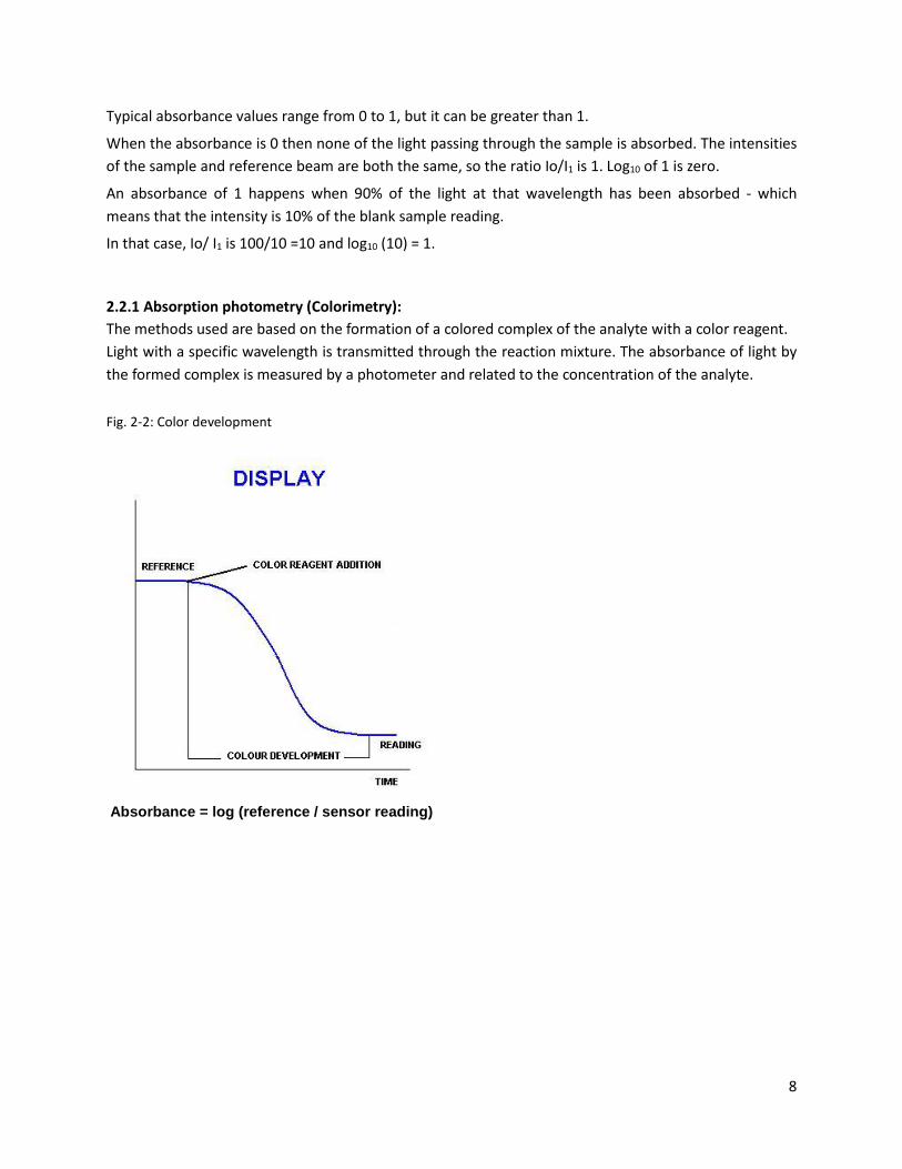
2.2.1 Absorption photometry (Colorimetry): The methods used are based on the formation of a colored complex of the analyte with a color reagent. Light with a specific wavelength is transmitted through the reaction mixture. The absorbance of light by the formed complex is measured by a photometer and related to the concentration of the analyte.
Fig. 2-2: Color development
Absorbance = log (reference / sensor reading)
8

2.3 Analysis Cycle A typical Analysis Program in the Model CA-6 has the following structure: Rinse the colorimetric reaction cell with the sample and fill the cell with the sample, add one or more reagents like a buffer or masking agent and then make the first measurement, the Reference measurement. The reference measurement eliminates interfering factors such as sample color and turbidity, miscellaneous color from the reagents and refractive index variations. After the reference reading, the color producing reagents are added. The sample is mixed and allowed time to complete the color forming reactions before taking the second measurement, the Reading measurement. The reference and reading values are used to calculate the concentration using the calibration factor. The reaction cell is drained and rinsed several times before starting the next measurement.
Fig. 2-3 Flow diagram
2.3.1 Typical Run Sequence: Conditioning, rinsing and sampling Drain, rinse and sample functions
First the cuvette is drained and rinsed (these steps can also be programmed at the end of the run). The hydraulic lines and the colorimetric cell are rinsed prior to taking the actual sample. Then the sample is taken.
Addition of reagent(s) Add reag function
Depending on the method one or more reagents are added before the reference reading.
Mixing and wait The mixing pump is activated and the liquid is pumped from the lower part to the upper part of the colorimetric cell. The waiting
9
Mix and wait functions
time is programmed in order to eliminate bubbles and allow suspensions to settle ...
First measurement Reference function
Measures the light intensity for the base reference value, in order to start from a fixed reference point and eliminate interfering factors (sample turbidity, color...).
Addition of color reagent(s) Add reag function
Depending on the method one or more reagents may be added for the color development.
Mixing and wait Mix and wait functions
The mixing pump is activated and liquid is pumped from the lower part to the upper part of the colorimetric cell; mixing the sample and the reagent(s). The waiting time is programmed to provide adequate time to complete the colorimetric reaction.
Reading, absorbance and concentration calculation Absorbance and Calculation
Reading of the light intensity after the colorimetric reaction, calculation of the absorbance and of the concentration.
Drain, conditioning, rinsing, sampling Drain, rinse and sample functions
Drain and rinse of the hydraulic lines and the colorimetric cell.
Waiting time (analysis frequency) Wait function
The wait function allows the frequency of the analysis to set.
2.3.2 Settings Analysis cycle – Extra cycle (second level password, administration) These menus list the sequence of programmable operations run by the analyzer. See actual program sequences in Section 11 at the rear of the manual.
Both the Analysis Cycle and the Extra Cycle menus have 30 programmable steps. Each step has an operation and a time associated with it. The time of the operation is in seconds and the maximum programmable value is 900 seconds. See the list of operations on the following pages. The operations of absorbance, calculation, calibration, validation, blank and print require only few seconds, 1-2 seconds each.
The modular design and easily programmed operations make it possible to automate most any colorimetric laboratory method with up to 4 reagents.
10
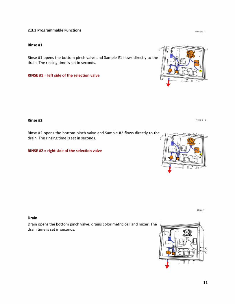
2.3.3 Programmable Functions
Rinse #1 Rinse #1 opens the bottom pinch valve and Sample #1 flows directly to the drain. The rinsing time is set in seconds. RINSE #1 = left side of the selection valve
Rinse #2 Rinse #2 opens the bottom pinch valve and Sample #2 flows directly to the drain. The rinsing time is set in seconds. RINSE #2 = right side of the selection valve
Drain Drain opens the bottom pinch valve, drains colorimetric cell and mixer. The drain time is set in seconds.
11

Sample #1
Sample #1 actuates the peristaltic pump with the bottom pinch valve closed and the colorimetric cell fills with sample #1. The sample time is set in seconds. SAMPLE #1 = left side of the selection valve
Sample #2 Sample #2 actuates the peristaltic pump with the bottom pinch valve closed and the colorimetric cell fills with sample #2. The sample time is set in seconds. SAMPLE #2 = right side of the selection valve
Dilution options
Loop On Loop On allows the sample liquid (sample line #1) that is to be diluted to flow through the Sample Loop. The Loop On time is set in seconds.
Loop off Loop Off traps the sample inside the loop tubing while the sample fluid is flushed from the lines with the dilution water. The Loop off time is set in seconds.
Loop On Loop On for the dilution fluid, DI water (sample line #2), dilutes the sample in the loop tube and fills the Colorimetric Cell.
12

Aux on Aux On activates an optional auxiliary operation (a digestion, oxidation or auto-function for a dilution configuration). The picture shows the oxidation option (On switches the UV lamp on). Aux off Aux Off stops the optional auxiliary operation. Add rea #1 Add rea #1 turns on the micro peristaltic pump for the addition of reagent #1. The mixing pump is circulating the sample as the reagent is being added. The Add Rea #1 time is set in seconds. Add rea #2 Add rea #2 turns on the micro peristaltic pump for the addition of reagent #2. The mixing pump is circulating the sample as the reagent is being added. The Add Rea #2 time is set in seconds.
13

Add rea #3 Add rea #3 turns on the micro peristaltic pump for the addition of reagent #3. The mixing pump is circulating the sample as the reagent is being added. The Add Rea #3 time is set in seconds.
Add rea #4 Add rea #4 turns on the micro peristaltic pump for the addition of reagent #4. The mixing pump is circulating the sample as the reagent is being added. The Add Rea #4 time is set in seconds.
Wait The waiting time is set in seconds. Wait puts the CA6 in Stand By mode.
Mix The mixing time is set in seconds.
Reference The reference measurement is the first point for the calculation of the absorbance, I0. Reference sets the time, in seconds, of when to take the base intensity measurement.
Absorbance Absorbance sets the time, in seconds, of when to take the colored intensity measurement, the Reading, I1, and calculate the absorbance, I0/ I1. Typically 1 – 2 seconds
Calculation Calculation sets the time in seconds to convert the absorbance reading into a concentration reading and sends the calculated value to the main display. Calculation uses the absorbance reading and the calibration factor. Typically 1 – 2 seconds
14
Calibration Calibration sets the time, in seconds, to calculate and record a new calibration factor after a calibration extra cycle, Auto Calibration. Typically 1 – 2 seconds
Validation Validation sets the time, in seconds, to calculate and display % Validation of a Known Standard in the display screen using the current calibration factor as a calibration check. A 5 ppm sample reading 4.8 ppm, displays 96% after the validation extra cycle. Typically 1 – 2 seconds
Blank The Blank function sets the time, in seconds, to enter a new blank calibration, calculating and recording the new blank value in the calibration screen after a Blank extra cycle. Typically 1 – 2 seconds
Save Dtlog Allows the measurement's reading to be saved in the internal Datalogger, Typically 1 – 2 seconds, the datalog register is only written to after the internal 24 hour clock resets to 00:00:00
Relay #1 The Rele #1 setting allows a time, in seconds, to be assigned to the activation of relay 1. The relay configuration is set in the Service Menu.
Relay #2 The Rele #2 setting allows a time, in seconds, to be assigned to the activation of relay 2. The relay configuration is set in the Service Menu.
2.4 Components The CA-6 Analyzer has three distinct sections:
1. The Liquids Section which includes all of the liquid handling equipment. This is located in the Lower Compartment, (pictured right, with Dilution Module).
2. The Electrical Section including power supply, microprocessor controller, I/O and touch screen interface are located in the Upper Compartment.
3. Reagents Section, the CA-6 can use up to 4 reagents, these containers are typically stored below or beside the analyzer.
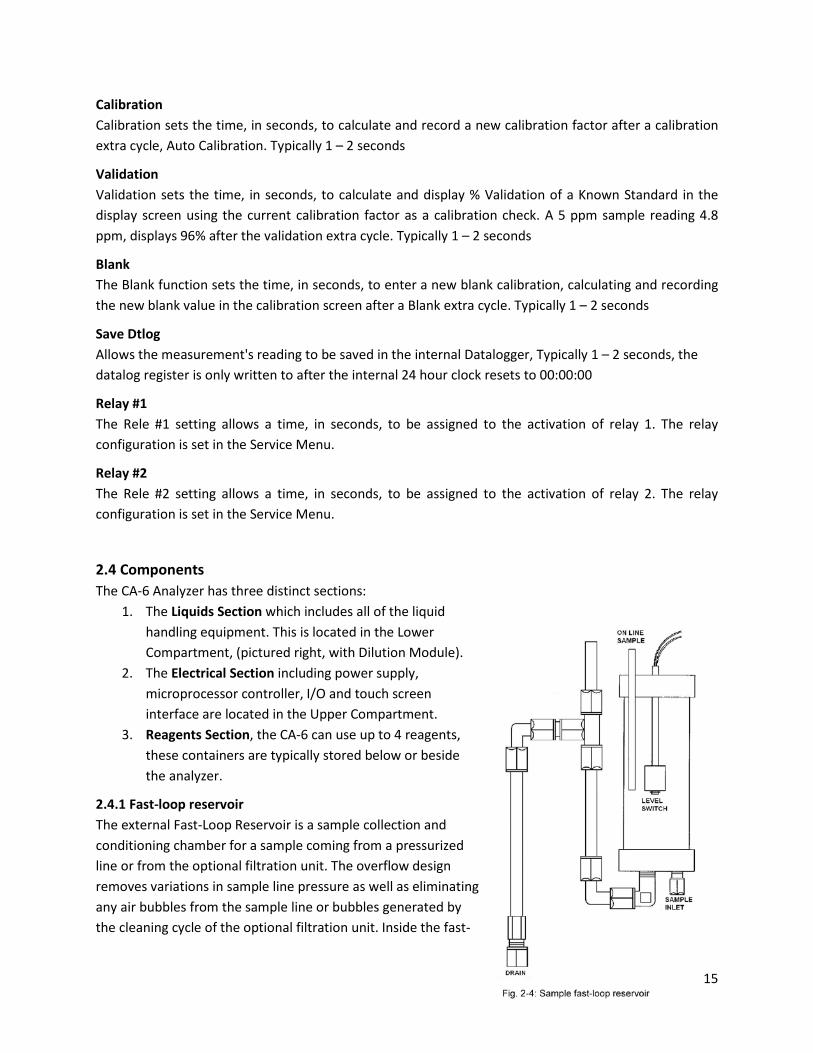
2.4.1 Fast-loop reservoir The external Fast-Loop Reservoir is a sample collection and conditioning chamber for a sample coming from a pressurized line or from the optional filtration unit. The overflow design removes variations in sample line pressure as well as eliminating any air bubbles from the sample line or bubbles generated by the cleaning cycle of the optional filtration unit. Inside the fast-
15

loop reservoir the sample is at atmospheric pressure and this allows the sample pump to provide a consistent sample delivery to the colorimetric cell. In addition, the fast-loop reservoir provides an extra quantity of sample in case of an interruption in the sample flow. The stainless steel drain tubing keeps a constant sample level inside the container. The sample flow should be adjusted for a continuous sample overflow through the stainless steel drain tube thereby providing ample circulation to avoid suspended solids accumulation in the reservoir. A small hole at the top of the stainless steel drain tubing allows the fast-loop reservoir to be easily emptied for cleaning purposes. The Fast-Loop reservoir uses a level sensor to verify sample volume. The loss of sample triggers the level switch which places the analyzer in stand-by mode at the end of the current measurement cycle. When the sample flow returns and refills the reservoir, the analyzer will automatically start a new cycle.
2.4.2 Sampling Pump Model CA-6 uses a Masterflex® peristaltic pump for sampling. The Model # of the pump is printed on the cover and the Model # includes the two digit tubing size designator. Proper diameter and material of the tubing must be used for proper functioning of the CA-6 Analyzer, use only ECD replacement tubing and parts. The pump is located in the liquid enclosure.
2.4.3 3 Way Valve The use of 3 Way Valves allows the CA-6 to perform automatic operations. An operator can set up auto-calibration, auto-validation or auto-cleaning functions. The valve is located in the liquid enclosure.
2.4.4 Micro Peristaltic Pumps The reagents are dispensed with “Micro Peristaltic Pumps“. Up to 4 pumps can be installed in the analyzer, allowing the use of up to 4 different reagents. Every 1 second pulse of the pump allows a 0.05 ml dose of reagent. The pumps are located in the liquid enclosure.
2.4.5 Mixing Pump The sample and reagents are mixed with a diaphragm pump. The liquids are pumped from the lower part of the colorimetric cell to the upper part for a specified period of time. Flow direction (inlet / outlet) of the pump is indicated with the symbols (V) and (Λ) on the pump body. The mixing pump is located in the liquid enclosure.
2.4.6 Pinch Valve The normally-closed pinch valve is used to control the draining or rinsing of the colorimetric cell. When the valve is actuated it opens and drains the cell. The valve can be manually actuated by pressing the black plastic face. The pinching jaws are sized for ⅜” O.D. Silicon or Viton tubing. The size and material of the tubing is VERY IMPORTANT, use only ECD spares. The pinch valve is located in the liquid enclosure. This tubing should be checked regularly for proper sealing.
16
2.4.7 Colorimetric Reaction Cell The colorimetric reaction cell is made of Quartz glass with a diameter of 16 or 25 mm, depending on the measured parameter. The cell is located inside a thermostatic block held in place with 2 thumb screws. The block can be easily removed to allow the cleaning of the glass cell.
2.4.8 Sample Drain Tubing for the sample drain maintains a constant level of few cm of liquid in the colorimetric cell.
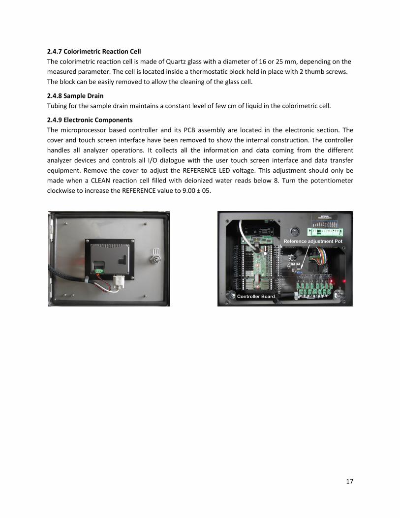
2.4.9 Electronic Components The microprocessor based controller and its PCB assembly are located in the electronic section. The cover and touch screen interface have been removed to show the internal construction. The controller handles all analyzer operations. It collects all the information and data coming from the different analyzer devices and controls all I/O dialogue with the user touch screen interface and data transfer equipment. Remove the cover to adjust the REFERENCE LED voltage. This adjustment should only be made when a CLEAN reaction cell filled with deionized water reads below 8. Turn the potentiometer clockwise to increase the REFERENCE value to 9.00 ± 05.
17
3.0 OPTIONS Two popular options are the Dilution Module, allowing over range samples to be diluted into the proper measurement range and the Oxidation Module, used to break down complex molecules into measurable constituents.
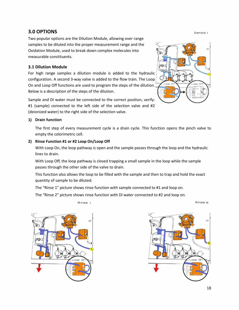
3.1 Dilution Module For high range samples a dilution module is added to the hydraulic configuration. A second 3-way valve is added to the flow train. The Loop On and Loop Off functions are used to program the steps of the dilution. Below is a description of the steps of the dilution.
Sample and DI water must be connected to the correct position, verify: #1 (sample) connected to the left side of the selection valve and #2 (deionized water) to the right side of the selection valve.
1) Drain function
The first step of every measurement cycle is a drain cycle. This function opens the pinch valve to empty the colorimetric cell.
2) Rinse Function #1 or #2 Loop On/Loop Off With Loop On, the loop pathway is open and the sample passes through the loop and the hydraulic lines to drain.
With Loop Off, the loop pathway is closed trapping a small sample in the loop while the sample passes through the other side of the valve to drain.
This function also allows the loop to be filled with the sample and then to trap and hold the exact quantity of sample to be diluted.
The “Rinse 1” picture shows rinse function with sample connected to #1 and loop on.
The “Rinse 2” picture shows rinse function with DI water connected to #2 and loop on.
18

3) Sample Function #1 or #2 Loop Off / Loop On
With the Sampling function, the sample pump is activated and the pinch valve (to drain) is closed. De-Ionized water (#2) is used to fill the colorimetric cell after passing through the loop.
Loop On, the loop pathway is open. This releases the sample contained inside the loop to mix with the DI water (#2) passing through the loop, In this way the sample quantity trapped in the loop during the Rinse Cycle is mixed with DI water and transferred to the colorimetric cell for the colorimetric analysis.
Loop Off, the loop pathway is closed and liquid does not pass through the loop. Sample 1 picture shows the sample function with sample connected to #1 and loop on or off.
After the dilution, the colorimetric reaction is performed.
3.2 Oxidation/Digestion Module For the detection of some parameters (for example TP, TN, NO3...) it is necessary to perform a
photochemical oxidation or digestion before the colorimetric reaction. In these cases the Oxidation
Module option is added to the Liquids section.
To ensure a complete oxidation of the sample, the oxidation can be performed using sulfuric acid, heat,
UV irradiation and/or a chemical oxidizer.
DANGER!
Below is a list of possible hazards to be considered when the oxidation / digestion module is included
in a CA-6 analyzer:
19

Hazard of chemical burns
This symbol is used to represent the hazard of severe burns and serious injury from handling dangerous chemicals. All handling and maintenance operations on chemicals labeled with this symbol should be made by qualified personnel in accordance with national or local regulations. Qualified Personnel means a person who has been fully trained and has professional experience to avoid chemical hazards and dangers. Before handling these chemicals or proceeding with service operations, read the material safety data sheets supplied with each chemical to take all the necessary precautions when handling.
Hazard of UV radiation
This symbol is used to represents a hazard from ultraviolet radiation. It is mandatory to wear eye protection when operating or servicing UV lamps labeled with this symbol. Never look directly at a lighted UV lamp. UV radiation exposure can cause severe and permanent damage to skin and eyes.
Hazard of hot surface
This symbol is used to present a hazard from hot surfaces.
Do not touch the oxidation / digestion module during operation.
Method Description:
After rinsing the hydraulic line, the sample is pumped with the peristaltic pump into the reaction cell.
The oxidation can be performed with:
• the addition of a chemical oxidizer (for example sodium persulfate or potassium peroxodisulfate) using the Micro Peristaltic Pump
• the addition of sulfuric acid, using a Micro Peristaltic Pump
• UV irradiation (photochemical)
• heating the cell
The sample and reagents are mixed using the diaphragm pump until the oxidation cycle is complete.
After the oxidation, the colorimetric reaction is performed to measure the concentration of the specific parameter present in the sample.
20

4.0 INSTALLATION
4.1 Unpacking and Inspecting The CA-6 Analyzer is fully assembled and was tested for proper performance at the factory before packaging and shipping. Before proceeding with installation of the analyzer, it is recommended that you carefully inspect the box and analyzer for damage that may have occurred during shipping.
Use care when unpacking and moving the analyzer. Refer to the Packing List when unpacking the CA-6 Analyzer and be careful not to misplace any of the accessories.
4.2 Analyzer Handling Use extreme care when lifting or moving the analyzer. If the analyzer has been in service, empty all liquids from the hydraulic parts before moving the analyzer.
4.3 Location and Mounting Instructions Install the CA-6 Analyzer in a clean, dry and dust free environment or in an enclosure with good ventilation.
Environmental Operating conditions are:
• Temperature: 5° to 50°C (41° - 121°F) • Relative humidity: 80% maximum
If the temperature is below 5°C (41°F), the analyzer should be installed in a heated cabinet.
Due to the possible generation of chemical or waste gases, choose a well ventilated location for the analyzer.
The Model CA-6 analyzer is supplied with four mounting brackets for wall mounting or stainless steel support rack installation. To Wall or Rack mount the CA6 analyzer use (4) ¼-20 screws or larger. The Reagent bottles are supplied with the analyzer. The relative position of the reagent bottle(s) to the reagent pump(s) is very important. The maximum distance between the bottom of the reagent bottle(s) and the lowest edge of the analyzer panel shall be no more than 40 cm (15.75”).
4.4 Pre-Installation Considerations for the proper Location of the CA-6 Analyzer:
• Place the analyzer close to the sample point in order to minimize the response time. • The sample point should provide a homogenous and representative sample to the CA6. • Position the CA-6 Analyzer near a suitable drain, with sufficient capacity to handle the gravity
fed waste discharge and the bypass overflow from the Fast Loop Reservoir (if used). WARNING: The sample drain from the analyzer must drain at ambient pressure with no restrictions or counter pressure.
• Clearance requirements for the analyzer should be 8 inches (20 cm) on either side of the analyzer and 40 inches (100 cm) on the front.
21

• Sufficient space for the reagent containers should be provided beside or beneath the analyzer. • The reagent containers should be placed in a suitable collection basin in case of spills.
Note: 15.75” maximum height between the reagent's bottle(s) and the reagent's pump(s).
4.5 Electrical Connections
4.5.1 General information The electrical installation should be carried out by qualified personnel in accordance with all national and local regulations. Qualified Personnel refers to a person who has the professional training and experience to avoid electrical hazards and dangers.
Only Qualified Personnel should have access to the key that opens the analyzer enclosure.
Power to the CA-6 Analyzer should be routed through an ON/OFF switch.
Turn off the power before beginning any service on the CA-6 Analyzer.
The CA-6 must be properly grounded to prevent the possibility of electrical shock. All metal surfaces are connected to the Ground terminal. The Grounding Terminal/Screw is located inside the electrical enclosure in the upper left position.
It is the user’s responsibility to periodically check the efficacy of analyzer’s
electrical ground.
The analyzer stops when power is lost or disrupted and automatically restarts when
the power is restored.
Users and qualified maintenance personnel must proceed as follows:
• Always turn off the power before servicing the analyzer • Take notice of all Electrical Shock and/or Electrocutions labels placed on the analyzer
DANGER:
No Service should be carried out on the instrument without first switching off the
power.
22
4.5.2 AC Power Connections The CA-6 Analyzer is designed for operation with 110-220Vac, 50-60 Hz power. The supplied AC power
cord exits through a port on the top side of the electrical compartment. All the connections must be
made in accordance with national or local regulations. The analyzer is equipped with a thermal switch
(main power switch). It is recommended that the CA-6 analyzer is connected to power via a circuit
breaker or an ON/OFF switch installed near the unit.
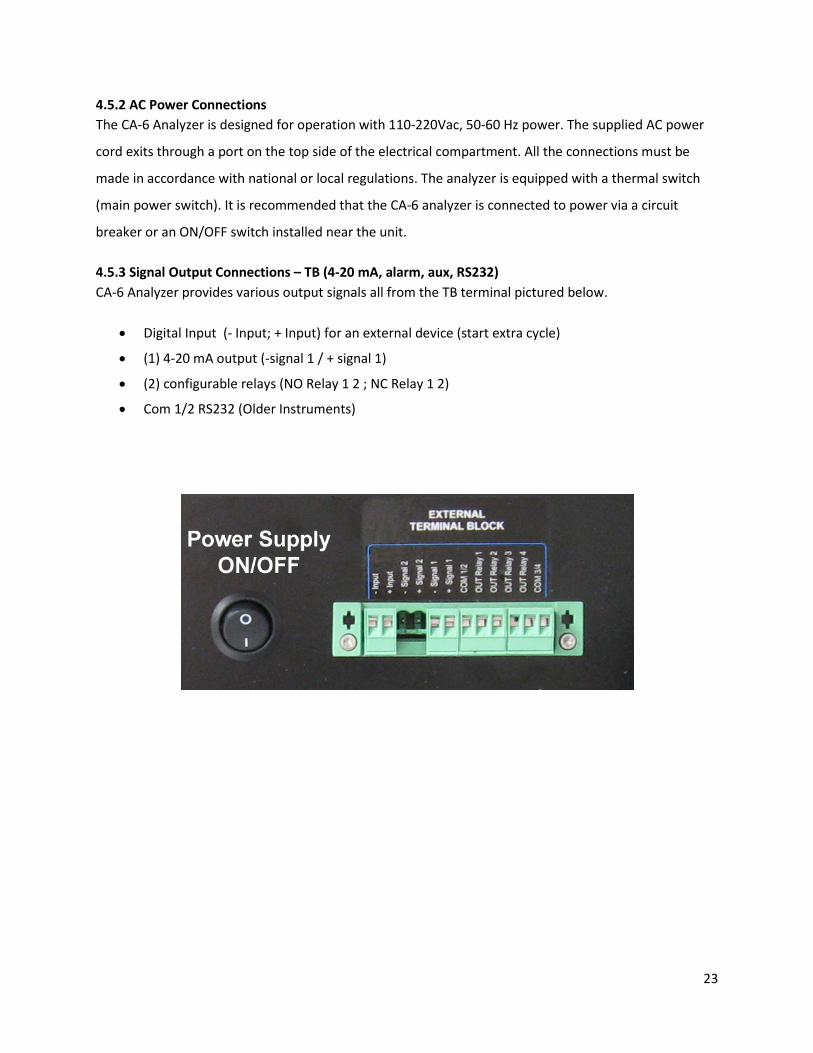
4.5.3 Signal Output Connections – TB (4-20 mA, alarm, aux, RS232) CA-6 Analyzer provides various output signals all from the TB terminal pictured below.
• Digital Input (- Input; + Input) for an external device (start extra cycle)
• (1) 4-20 mA output (-signal 1 / + signal 1)
• (2) configurable relays (NO Relay 1 2 ; NC Relay 1 2)
• Com 1/2 RS232 (Older Instruments)
23

5.0 REAGENTS PREPARATION Each analyte uses its own set of reagents to develop the distinctive color for measurement. The recipes for the specific reagents required for this measurement are listed in Section 11.4 at the end of the manual. Each recipe details the chemicals used and the procedures used to produce the reagent. Read all MSDS data sheets before preparing the reagents. Use good laboratory technique. Wear safety goggles, gloves and protective clothing when preparing the reagents, calibration solutions or cleaning solutions. Mind all Hazard and Poison labels Pre-made reagents and solutions are available from ECD. The part #s for the reagents can be found in the recipe next to the reagent name and in section 9.3 Accessories and Spare Parts. Several of the reagents are listed as Hazardous Shipping Materials; these materials are only available for shipment domestically inside the USA.
5.1 Method of Analysis The aluminum determination is a colorimetric analysis in a 16 mm diameter heated colorimetric cell using a 572 nm LED. After rinsing the hydraulic lines, the sample is pumped with the peristaltic pump into the colorimetric cell. Reagent 1, the acidic pyrocatechol violet dye, is added using MicroPump 1. The aluminum in the sample reacts to form a purple aluminum pyrocatechol complex and the reference value is measured. Reagent 2, the sodium acetate pH buffer, is added to raise the pH to between 6.2 and 6.4 pH, changing the aluminum complexed pyrocatechol green. The sample is mixed and allowed to settle before the Absorbance is measured and the result is displayed.
The Aluminum analysis is pH dependant and will only work properly between 6.2 and 6.4 pH. Mix 10.0 ml of sample water with 0.90 ml of reagent 1 and 0.90 ml of reagent 2. Measure the pH, increase the amount of reagent 2 if the pH is below 6.2 pH and decrease the amount of reagent 2 if the pH is higher than 6.4 pH.
Before proceeding with the analyzer Start-Up, check that all installation (Section 4.0) and reagent preparation (Section 11.0) operations have been properly completed. Please
verify that all suggestions and recommendations have been followed.
24

6.0 ANALYZER INITIAL START-UP
• Open The Liquids Compartment • Disconnect LED Cable from upper left
corner of the back panel, twist ¼ turn counter clockwise then pull back.
• Remove the protective paper surrounding the colorimetric cell by unscrewing the two (2) thumbscrews and carefully removing the heater/LED block, remove the paper, replace the block and gently retighten the thumbscrews. Reconnect LED.
• Remove the block from the Drain Pinch Valve by pressing the black button. Save for future use. It removes compression from the drain tube when the CA6 is not in use.
• Install the Fast Loop Reservoir close to the right side of the CA-6 Analyzer.
6.1 Sample and Drain Tubing Connections After double checking Sections 4.0 & 5.0, proceed as follows:
• Connect the overflow drain of the Fast-Loop Reservoir to the drain with 12 mm OD tubing.
• Connect the sample feed line (or the outlet of the optional filtering unit) to the bottom of the Fast-Loop Reservoir previously installed on the right side of the analyzer.
• SEE SECTION 11, ANALYSIS CYCLE, FOR ACTUAL TUBING CONNECTIONS
• Connect the sample inlet tubing from the analyzer, Sample #2, to the “Sample to Analyzer” port fitting on top of the Fast-loop Reservoir using 1/8” I.D. flexible tubing (Tygon, Pharmed or Norprene are recommended). The sample will now be taken from atmospheric pressure by the sample peristaltic pump.
• Connect the optional Dilution water, deionized or ultra pure, using 1/8” I.D. flexible tubing from the bottle to Sample port #1.
• Connect the reagents tubing (coming from the reagent bottle) to the corresponding REAGENT port fitting (Reagent 1 to Port 1) using 1/16” I.D. flexible tubing (Tygon, Pharmed or Norprene are recommended).
25

The reagents will be delivered to the optical cell by the internal reagent peristaltic pumps. Note the maximum height of 15.75” (40 cm) between the bottom of the bottle(s) and the bottom edge of the analyzer panel.
• Connect the analyzer drains (CELL and VENT DRAINS) to a waste line using 3/8” flexible tubing. WARNING: the drain from the analyzer must be at atmospheric pressure with no restrictions. The drain line should be properly sized to accommodate the overflow coming from external fast-loop reservoir and the gravity fed analyzed sample.
• Check sample level in the Fast-Loop Reservoir, if used, and adjust the sample flow rate to allow a continuous overflow to the drain line.
• Connect float valve switch from the Fast Flow reservoir to the connection on the upper right side of the CA6.
6.2 Powering, Priming and Starting the Analyzer
• Supply power to the analyzer. Turn ON Power Switch. The Main Menu will appear on the display. • Read the Installation and Start Up procedures in the (?) Help
Menu or Section 11 below. • Login with the 1st level password, SERVICE (1111). • Press the DISPLAY button on the touch screen • Press the MANUAL STEP button. This allows manual control
of the functions. • Select the SAMPLE 1 function, enter 13 seconds Press ON.
This starts the sample pump and it runs for 13 seconds filling the optical cell. After filling press and hold the Drain button. Repeat for SAMPLE 2 if present.
• The SAMPLE function fills the colorimetric cell with the sample. Check the optical signal on the chart. With an uncolored sample the red line should be approximately 9 (the reference value) when the optical cell is filled, 4-5 when empty.
• Select the ADD REAG 1 function and enter 30 seconds. This will prime the reagent peristaltic Pump. When primed, reagent will be seen dripping from the feed tube into the optical cell. Repeat with ADD REAG 2, 3, 4 as required.
• Verify the drain tube below the pinch valve is correctly positioned in the drain and is not kinked or bent which would restrict the flow.
• Select the DRAIN function and enter 5 seconds. (Drains cell) • Select the SAMPLE function and enter 20 (13) seconds. (Fills
cell with sample) • Verify the programmed settings of the Analysis Cycle/Extra
Cycle programs currently loaded in the analyzer, (PROGRAM
26

→ ANALYSIS CYCLE, protected with 2nd level password ADMIN 6699) agree with the Analysis Cycle/Extra Cycle detailed in Section 11 at the rear of the manual.
• Close all the menu windows and start the measurements by pressing the RUN button and then START ONLINE button for continuous on-line operation or choose the Cycle Ch1, Cycle Ch2 or the Extra button for a single analysis cycle.
27
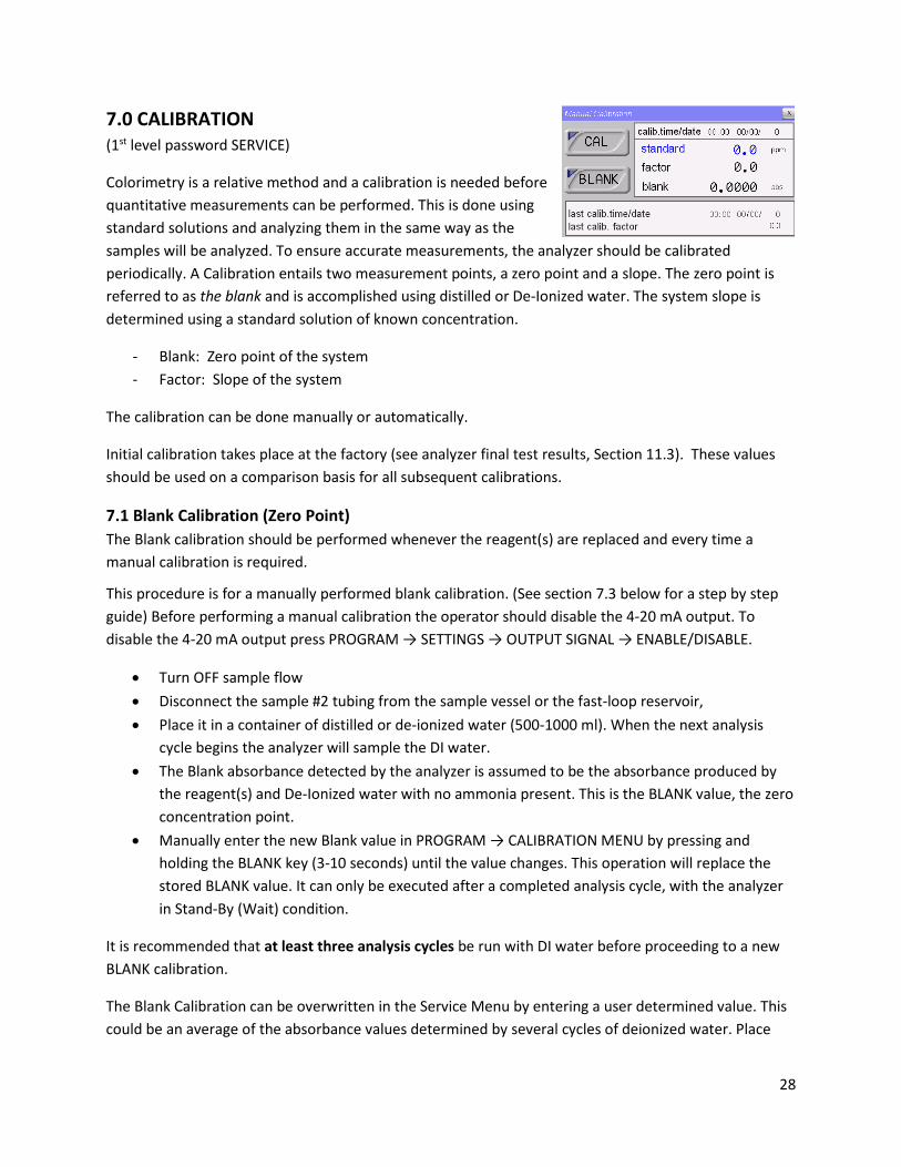
7.0 CALIBRATION (1st level password SERVICE)
Colorimetry is a relative method and a calibration is needed before quantitative measurements can be performed. This is done using standard solutions and analyzing them in the same way as the samples will be analyzed. To ensure accurate measurements, the analyzer should be calibrated periodically. A Calibration entails two measurement points, a zero point and a slope. The zero point is referred to as the blank and is accomplished using distilled or De-Ionized water. The system slope is determined using a standard solution of known concentration.
- Blank: Zero point of the system - Factor: Slope of the system
The calibration can be done manually or automatically.
Initial calibration takes place at the factory (see analyzer final test results, Section 11.3). These values should be used on a comparison basis for all subsequent calibrations.
7.1 Blank Calibration (Zero Point) The Blank calibration should be performed whenever the reagent(s) are replaced and every time a manual calibration is required.
This procedure is for a manually performed blank calibration. (See section 7.3 below for a step by step guide) Before performing a manual calibration the operator should disable the 4-20 mA output. To disable the 4-20 mA output press PROGRAM → SETTINGS → OUTPUT SIGNAL → ENABLE/DISABLE.
• Turn OFF sample flow • Disconnect the sample #2 tubing from the sample vessel or the fast-loop reservoir, • Place it in a container of distilled or de-ionized water (500-1000 ml). When the next analysis
cycle begins the analyzer will sample the DI water. • The Blank absorbance detected by the analyzer is assumed to be the absorbance produced by
the reagent(s) and De-Ionized water with no ammonia present. This is the BLANK value, the zero concentration point.
• Manually enter the new Blank value in PROGRAM → CALIBRATION MENU by pressing and holding the BLANK key (3-10 seconds) until the value changes. This operation will replace the stored BLANK value. It can only be executed after a completed analysis cycle, with the analyzer in Stand-By (Wait) condition.
It is recommended that at least three analysis cycles be run with DI water before proceeding to a new BLANK calibration.
The Blank Calibration can be overwritten in the Service Menu by entering a user determined value. This could be an average of the absorbance values determined by several cycles of deionized water. Place
28
the sample tube in a gallon of De-ionized water, Press RUN ONLINE. After 1 hour, 5 cycles will be completed. Press RUN, Emergency Stop, RUN, RESET Emergency Stop. The analyzer will be in Stand by Mode (WAIT). Press Display, Datalog, average the last 3 absorbance values. Enter the average in the Blank window of the Service Menu.
7.2 Slope Calibration (Factor) Set the value of the standard solution to be used for the calibration by pressing PROGRAM → CALIBRATION MENU → STANDARD, enter the value of the calibration solution.
This procedure is for a manually performed slope calibration (Factor). (see section 7.3 below for a step by step guide)
• Disconnect the sampling tubing from the sample line or fast-loop reservoir (if present), • Place sample tube into a container of standard solution. When a new analysis cycle begins, the
analyzer will sample the standard solution. • The absorbance detected by the analyzer is assumed as the absorbance produced by the
standard solution. • The stored BLANK value is subtracted from the Standard Solution Absorbance and the factor
value is calculated. The FACTOR is manually entered by pressing and holding the CAL key (3-10 seconds) in the CALIBRATION MENU until the FACTOR value changes. This operation will replace the stored FACTOR value. It can only be executed after a completed analysis cycle, with the analyzer in Stand-By (Wait) condition.
It is recommended that at least three analysis cycles be run with standard solution before proceeding to a new FACTOR calibration.
The FACTOR Calibration can be overwritten in the Service Menu by entering a user determined value. This could be an average of the absorbance values determined by several cycles of Standard Solution. Place the sample tube in a gallon of Standard Solution, Press RUN ONLINE. After 1 hour, 5 cycles will be completed. Press RUN, Emergency Stop, RUN, RESET Emergency Stop. The analyzer will be in Standby Mode (WAIT). Press Display, Datalog, average the last 3 Absorbance values. The Standard Solution value divided by the average absorbance equals the FACTOR. Enter the value in the FACTOR window of the Service 2 Menu. The Service 2 Menu is accessed by pressing ¼” to the left of the Close (X) of the Service 1 Menu.
7.3 Step by Step Manual Calibration
Before performing a manual calibration the operator should disable the 4-20 mA output. To disable the 4-20 mA output press PROGRAM → SETTINGS → OUTPUT SIGNAL → ENABLE/DISABLE.
1. Disconnect the sampling tubing coming from the fast-loop reservoir (if present). 2. With the sampling tube connected to port #2 of the 3 way valve, place the other end in a
container of distilled water (500ml – 1000ml). Keep the door Closed during operation. 3. From the Main Menu select RUN → Cycle Ch 1.
29
4. When the analysis cycle begins the analyzer will sample the DI water and automatically run 1 analysis cycle and then stop and enter the Stand-By (Wait) mode. Repeat 2 times.
5. After the third cycle press PROGRAM → CALIBRATION MENU key (Password protected, Service 1111) to open the calibration menu window. Press and hold the BLANK button until the value changes. This operation will replace the stored BLANK value.
6. Remove the sampling tubing from the DI water and place it in the standard solution container. 7. Verify or enter the value of the standard solution used for the calibration by pressing PROGRAM
→ CALIBRATION MENU → STANDARD. 8. From the main menu select RUN → Cycle Ch 1. When the new analysis cycle begins the analyzer
will sample the standard solution and automatically run 1 analysis cycle, then stop and enter the Stand-By (Wait) mode. Repeat 2 times.
9. After the third cycle press PROGRAM → CALIBRATION MENU to open the calibration menu window, press and hold the CAL button until the FACTOR value changes. This operation will replace the stored FACTOR value.
10. Remove the sample tube from the standard solution and reconnect the sample tube to the fast-loop reservoir (if present).
After manual calibration enable the 4-20 mA output, pressing PROGRAM → SETTINGS → OUTPUT SIGNAL → ENABLE/DISABLE. Start the sampling cycle by pressing RUN → Start On-Line.
30

8.0 USER INTERFACE
8.1 Touch Screen Display The user interface consists of the Touch Screen Display located on the front panel of the analyzer enclosure. All
input/output data, information, alarms and fault conditions are shown on the display while all commands and
settings may be transferred to the analyzer simply pressing the touch screen.
8.2 Passwords (****) Access to the various menus is password protected. There are three levels of security as described in the table below.
First level password (service): 1111
Second level password (admin.): 6699
No password access First level password access Second level password access
Main menu Display menu – Manual step Program menu – Analysis cycle
Display menu – Display process values
Program menu – Calibration menu Program menu – Extra cycle
Program menu - Settings Service Menu
Help
31
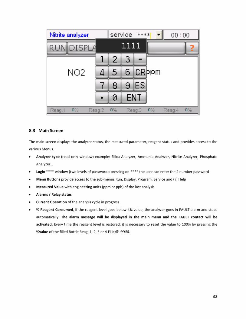
8.3 Main Screen
The main screen displays the analyzer status, the measured parameter, reagent status and provides access to the
various Menus.
• Analyzer type (read only window) example: Silica Analyzer, Ammonia Analyzer, Nitrite Analyzer, Phosphate
Analyzer…
• Login **** window (two levels of password); pressing on **** the user can enter the 4 number password
• Menu Buttons provide access to the sub-menus Run, Display, Program, Service and (?) Help
• Measured Value with engineering units (ppm or ppb) of the last analysis
• Alarms / Relay status
• Current Operation of the analysis cycle in progress
• % Reagent Consumed, if the reagent level goes below 4% value, the analyzer goes in FAULT alarm and stops
automatically. The alarm message will be displayed in the main menu and the FAULT contact will be
activated. Every time the reagent level is restored, it is necessary to reset the value to 100% by pressing the
%value of the filled Bottle Reag. 1, 2, 3 or 4 Filled? →YES.
32
8.3.1 Status Modes
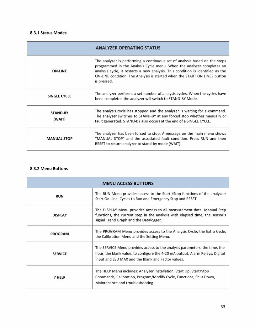
ANALYZER OPERATING STATUS
ON-LINE
The analyzer is performing a continuous set of analysis based on the steps programmed in the Analysis Cycle menu. When the analyzer completes an analysis cycle, it restarts a new analysis. This condition is identified as the ON-LINE condition. The Analysis is started when the START ON LINE? button is pressed.
SINGLE CYCLE The analyzer performs a set number of analysis cycles. When the cycles have been completed the analyzer will switch to STAND-BY Mode.
STAND-BY (WAIT)
The analysis cycle has stopped and the analyzer is waiting for a command. The analyzer switches to STAND-BY at any forced stop whether manually or fault generated. STAND-BY also occurs at the end of a SINGLE CYCLE.
MANUAL STOP The analyzer has been forced to stop. A message on the main menu shows “MANUAL STOP” and the associated fault condition. Press RUN and then RESET to return analyzer to stand-by mode (WAIT)
8.3.2 Menu Buttons
MENU ACCESS BUTTONS
RUN The RUN Menu provides access to the Start /Stop functions of the analyzer: Start On-Line, Cycles to Run and Emergency Stop and RESET.
DISPLAY The DISPLAY Menu provides access to all measurement data, Manual Step functions, the current step in the analysis with elapsed time, the sensor's signal Trend Graph and the Datalogger.
PROGRAM The PROGRAM Menu provides access to the Analysis Cycle, the Extra Cycle, the Calibration Menu and the Setting Menu.
SERVICE The SERVICE Menu provides access to the analysis parameters, the time, the hour, the blank value, to configure the 4-20 mA output, Alarm Relays, Digital Input and LED MAX and the Blank and Factor values.
? HELP The HELP Menu includes: Analyzer Installation, Start Up, Start/Stop Commands, Calibration, Program/Modify Cycle, Functions, Shut Down, Maintenance and troubleshooting.
33

8.4 RUN MENU The RUN Menu provides access to the Start /Stop functions of the analyzer, Start On-Line, Cycles to Run and Emergency Stop.
8.4.1 START ON-LINE? By pressing this button the analyzer will start a continuous cyclic analysis based on the steps set in the Analysis Cycle of the PROGRAM menu. ONLINE is now displayed on the button. By pressing the button again, the analyzer will finish the cycle in progress and then wait in STAND-BY mode.
8.4.2 CYCLE Ch1 / CYCLE Ch2 / Cycle Extra This command starts the analyzer, performing one cycle of analysis on channel 1 or channel 2 or extra auto-function. At the end of the cycle, the analyzer will turn in stand-by conditions waiting for a new user’s command.
8.4.3 EMERGENCY STOP This command will immediately stop the analyzer at the current step of the analysis. The analyzer will go into MANUAL STOP condition. MANUAL STOP in red colored letters will appear on the main screen and the FAULT contact will be activated. To restart the analyzer after an emergency stop is necessary to reset the fault. Press RUN then RESET EM. STOP yellow colored letters and the analyzer will switch to STAND-BY mode.
34

8.5 DISPLAY MENU
8.5.1 Display Process Values The following is a list of the displayed parameters in this menu (read only values)
Sensor: Displays the current measurement of the sensor
Refer: Displays the saved reference value, typically set to 9.00. (first point for the absorbance calculation)
Reading: Displays the saved reading of the sensor that was used for the absorbance calculation. (second point for the absorbance calculation)
Absorb: Displays the last absorbance value calculated.
Blank: Displays the absorbance value of the Blank.
Led: Displays the led voltage supply.
Valid %: Displays the validation value in percent, current reading in calibration solution compared to the calibration value.
Current operation: Displays the current analysis step and time (countdown for the programmed step).
8.5.2 Chart It displays a graph of the sensor's signal trend during the current analysis cycle, scaled 0-10 arbitrary units, readings higher than 10.00 go off the visible graph. Press CANCEL in the lower left corner of the graph to reset the graph.
8.5.3 Manual Step This selection provides manual control to each of the programming steps (see list in the section 2.3.1). The
operator can choose which single operation to run (select function) and set the time of the operation. This
function is protected with the 1st level password and is available only in STAND-BY mode.
35

8.6 PROGRAM MENU
Menu Functions:
Analysis Cycle Allows the user to program the 30 steps available in the Analysis Cycle. This function is protected with the 2nd level password.
Extra Cycle Allows the user to program the 30 steps available in the Extra Cycle. This function is protected with the 2nd level password.
Settings Set the ratio of the Analysis Cycles to Extra Cycles, the Alarm Value (low or high), the 4-20 mA Output and to Enable or Disable the Loss of Sample Alarm.
Calibration Menu
Allows the user to perform Blank and Factor Calibrations and to enter the value of the Standard Solution used for calibration. This function is protected with the 1st level password.
8.6.1 Analysis Cycle Analysis Cycle displays the numerical step, the time (in seconds) and the function for each of the 30 available steps in the Analysis Program. Touching a function changes it to the next function in the list; all functions are available in this circular list.
36

8.6.2 Extra Cycle Program the 30 available steps with the function and the time in seconds.
8.6.3 Settings Menu Cycles Ratio: Program the ratio of the ANALYSIS CYCLES versus the EXTRA CYCLES (for example ANALYSIS 20 &
EXTRA CYCLE 1 means that every 20 ANALYSIS CYCLEs the analyzer will perform 1 EXTRA CYCLE.
Result alarm: Program the low / high
alarm value. The alarm is expressed in
percent of the full scale.
Output signal: Allows the user to enable or
disable the 4-20 mA output.
Sample alarm: Allows the user to enable
or disable the Loss of Sample Alarm.
CYCLE WAIT Enter the WAIT Time for Step
30 of the ANALYSIS CYCLE
8.6.2 Calibration Menu Allows the user to enter the value of the standard used for calibration
Perform manual Blank and Span Calibration
(refer to Section 7)
Displays:
• Calibration Standard Used
• Calibration Factor
• Blank absorbance value
• Calibration Date and Time
• Last Calibration Date and Time and
Factor
37
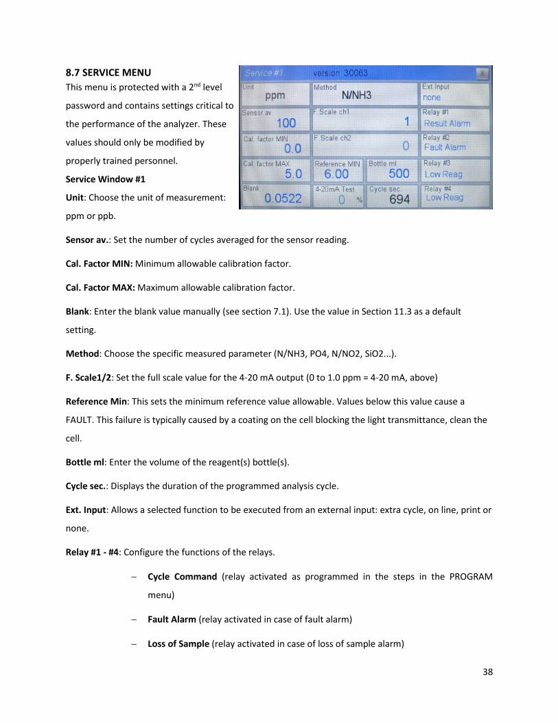
8.7 SERVICE MENU This menu is protected with a 2nd level
password and contains settings critical to
the performance of the analyzer. These
values should only be modified by
properly trained personnel.
Service Window #1
Unit: Choose the unit of measurement:
ppm or ppb.
Sensor av.: Set the number of cycles averaged for the sensor reading.
Cal. Factor MIN: Minimum allowable calibration factor.
Cal. Factor MAX: Maximum allowable calibration factor.
Blank: Enter the blank value manually (see section 7.1). Use the value in Section 11.3 as a default
setting.
Method: Choose the specific measured parameter (N/NH3, PO4, N/NO2, SiO2...).
F. Scale1/2: Set the full scale value for the 4-20 mA output (0 to 1.0 ppm = 4-20 mA, above)
Reference Min: This sets the minimum reference value allowable. Values below this value cause a
FAULT. This failure is typically caused by a coating on the cell blocking the light transmittance, clean the
cell.
Bottle ml: Enter the volume of the reagent(s) bottle(s).
Cycle sec.: Displays the duration of the programmed analysis cycle.
Ext. Input: Allows a selected function to be executed from an external input: extra cycle, on line, print or
none.
Relay #1 - #4: Configure the functions of the relays.
− Cycle Command (relay activated as programmed in the steps in the PROGRAM
menu)
− Fault Alarm (relay activated in case of fault alarm)
− Loss of Sample (relay activated in case of loss of sample alarm)
38
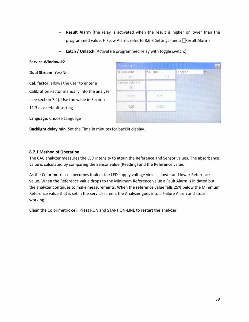
− Result Alarm (the relay is activated when the result is higher or lower than the
programmed value, Hi/Low Alarm, refer to 8.6.3 Settings menu Result Alarm)
− Latch / Unlatch (Activate a programmed relay with toggle switch.)
Service Window #2
Dual Stream: Yes/No.
Cal. factor: allows the user to enter a
Calibration Factor manually into the analyzer
(see section 7.2). Use the value in Section
11.3 as a default setting.
Language: Choose Language
Backlight delay min. Set the Time in minutes for backlit display.
8.7.1 Method of Operation The CA6 analyzer measures the LED intensity to attain the Reference and Sensor values. The absorbance value is calculated by comparing the Sensor value (Reading) and the Reference value.
As the Colorimetric cell becomes fouled, the LED supply voltage yields a lower and lower Reference value. When the Reference value drops to the Minimum Reference value a Fault Alarm is initiated but the analyzer continues to make measurements. When the reference value falls 25% below the Minimum Reference value that is set in the service screen, the Analyzer goes into a Failure Alarm and stops working.
Clean the Colorimetric cell. Press RUN and START ON-LINE to restart the analyzer.
39

8.8 ? HELP MENU Check these Help screens for the most up to date information.
40

8.8.1 Analyzer Installation
41
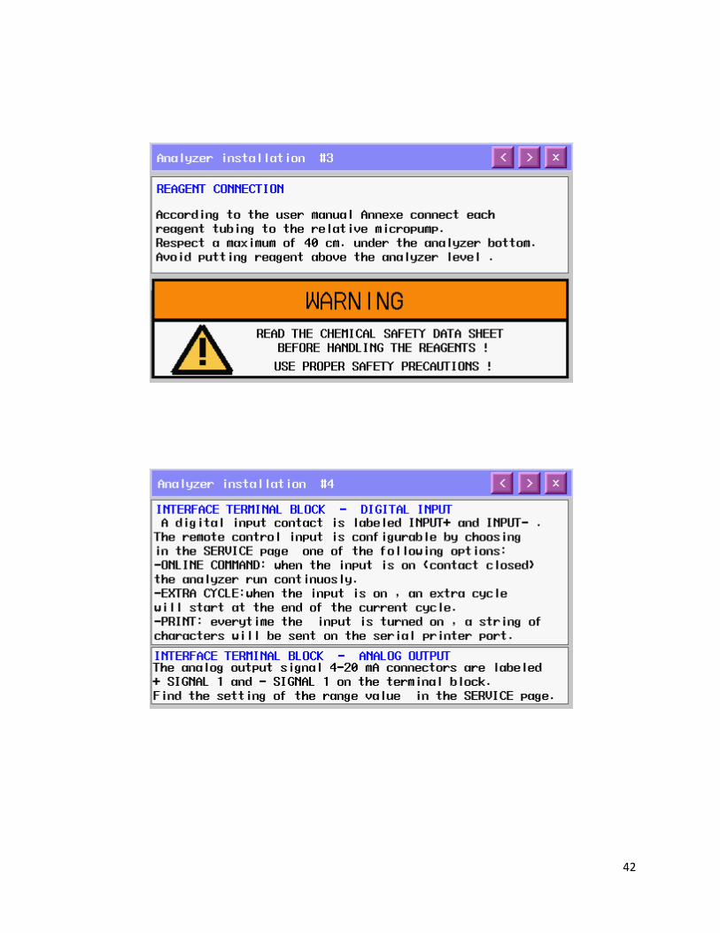
42

43
8.8.2 Analyzer Start Up
44

45
8.8.3 Start/Stop Commands
46
8.8.4 Calibrations
47

48
8.8.5 Program / Modify Cycles
49
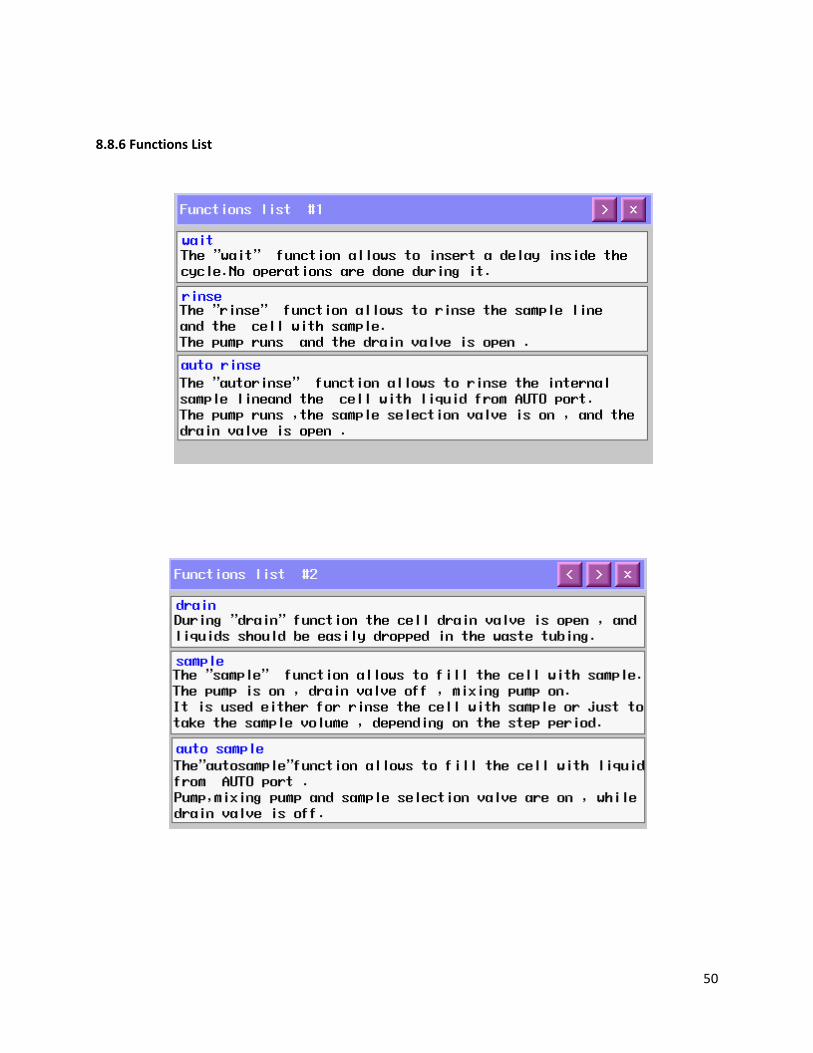
8.8.6 Functions List
50

51

52
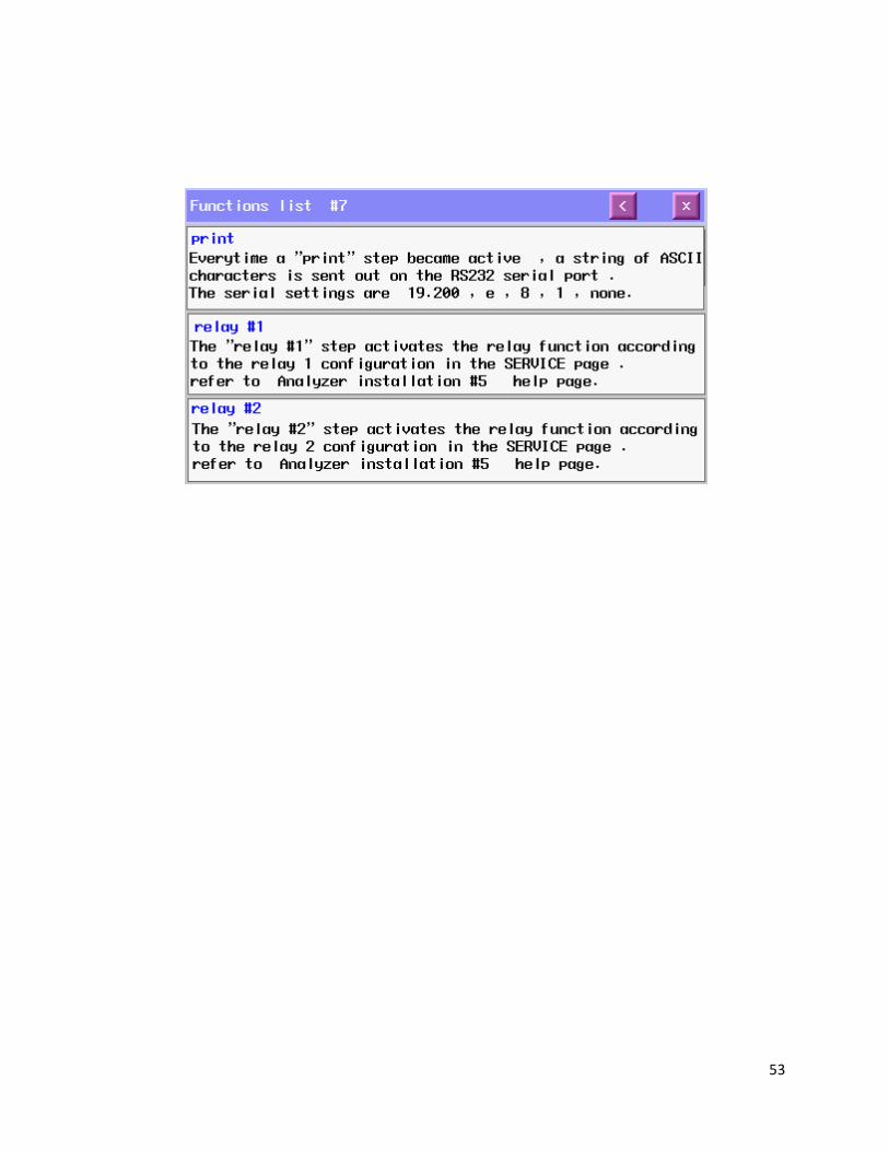
53
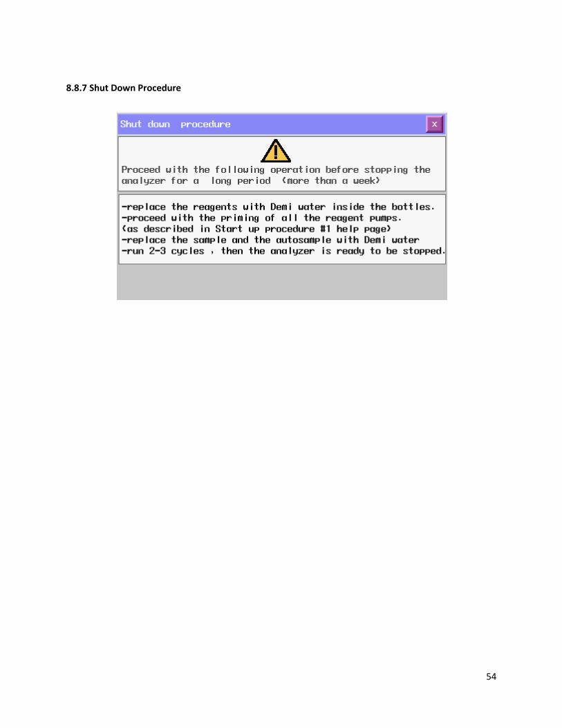
8.8.7 Shut Down Procedure
54
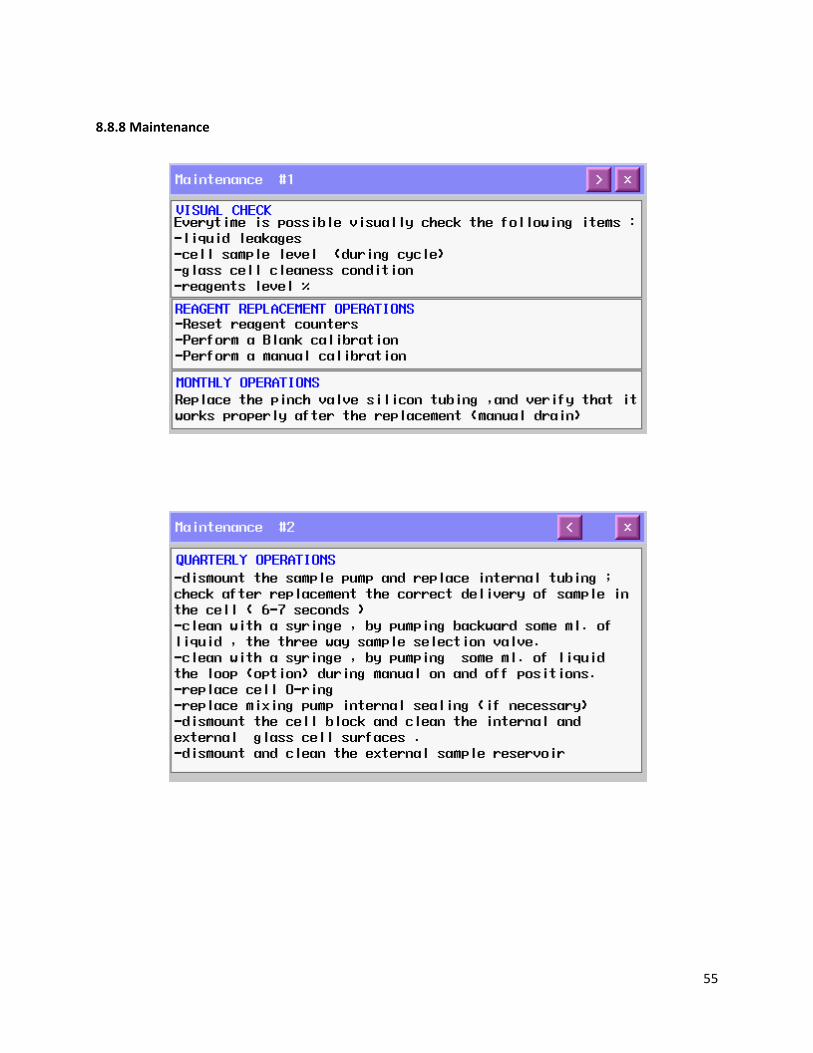
8.8.8 Maintenance
55
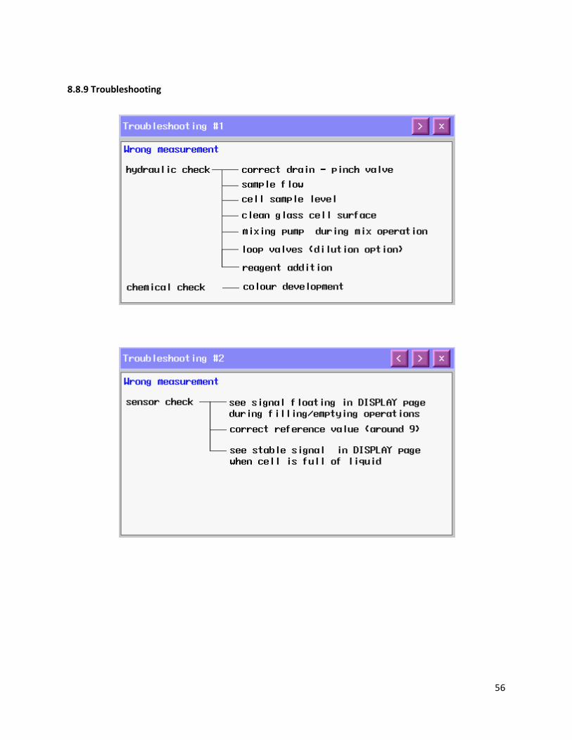
8.8.9 Troubleshooting
56
9.0 MAINTENANCE
Basic maintenance on the CA-6 Analyzer requires refilling or replacing reagent containers and cleaning
the colorimetric cell on a regular basis.
In addition we advise that you perform an overall visual check of the wetted parts for any leakage. If any
leaks are detected, take immediate corrective action. Cleaning of the analyzer cabinet is best performed
using a soft, non-aggressive cleaner.
The use of a logbook for registering reagent refilling, corrective measures and performed scheduled
maintenance is strongly recommended.
Switch off the power to the analyzer prior to the performance of the basic maintenance work, the CA6
Analyzer cannot be operational during maintenance. Prior to any maintenance work, take into
consideration all necessary precautions regarding personal safety (protective clothing, safety glasses
etc.).
Always label and rinse all connected tubing with water prior to removal.
! Caution
CA-6 Analyzer is based on colorimetric analysis methods, using chemical solutions.
Make sure proper safety precautions are taken (e.g. using safety gloves and glasses)
when handling chemical solutions.
List of maintenance operations:
9.0.1 Visual check Visually check the following items whenever possible:
• Liquid leakage
• Cell sample level (during cycle)
• Glass cell cleanliness and condition
• % Reagent levels
9.0.2 Monthly Visual Check (as above)
Replace Pinch Valve tubing
Clean the Colorimetric Cell
57
Replace Reagent(s) and reset reagent counters
Verify Micro Peristaltic pumps are primed and pumping
Run Calibrations:
• Blank with DI water,
• Slope with calibration solution
9.0.3 Every 4-6 months (depending on applications)
Replace Peristaltic Pump tubing
Manually clean 3 Way Valve(s), with a syringe
Clean Loop Valve (option) with a syringe
Replace Colorimetric Cell o-ring
Hydraulics tubing replacement
Replace Internal Seal of the mixing pump
Clean / Replace Fittings
9.0.4 Annual Analyzer general inspection (for qualified personnel only)
9.1 Sample Pump tubing replacement The peristaltic pump head is located in the Liquids section. Before replacing any tubing, carefully read
the Hazards and Dangers list in Section 1 and Health and Safety data sheets for the reagents. Always
wear protective clothing, gloves and eye protection. Use extreme care during tubing replacement to
avoid spills. See MasterFlex video at http://www.youtube.com/watch?v=zC1INbSnf8o .
Proceed as follows:
• Stop the analyzer and switch OFF the power.
• Using the key, open the liquids enclosure.
• Unscrew the four screws that hold the pump head in place.
• Disconnect the pump tubing from its inlet and outlet fittings, use caution to avoid liquid spills.
• Slide the pump head to the left and remove the pump head.
• Separate the two halves. Use care with the rotor and remove the used tubing.
• Place the half containing the rotor with the rollers in the 2, 6 and 10 o’ clock positions. Place
tubing in the outer groove and against the two rollers as shown. Keep your thumb on the tubing
to hold it in place and insert the tubing key on the back of the rotor shaft and push in as far as
58

possible. Tubing is now positioned in the pump head body. With the key firmly pressed against
the rotor, push down while turning counter clockwise until tubing is seated around the rotor.
• The tubing is now in place. Remove key and position other pump half into the rotor shaft and
snap shaft. Be careful not to pinch the tubing between the pump halves.
• Verify the pump turns correctly using the key.
• Slide the pump head onto the mounting screws moving the roller block with the key or with a
screwdriver until the shaft aligns with the motor drive.
• Secure the pump head with the four screws, hand tighten until it is firmly mounted.
• Restart the analyzer.
Figure 9-1: Pump tubing replacement details
9.2 Micro Peristaltic Tubing Replacement The Miniature Pump model peristaltic pumps are located in the liquid enclosure. Before proceeding to replace the tubing, it is recommended to wear adequate clothes, gloves and eyes protection and take extreme care with reagent spills during tubing replacement. (Read reagents' MSDS).
1. Stop the analyzer in stand-by. Open the liquids enclosure and disconnect the reagent's inlet line from its container taking caution to prevent liquid spills.
2. Using Manual mode activate the peristaltic pump for 10 seconds, the pump will suck air and the internal tubing will be empty of liquid.
3. Disconnect the outlet tubing taking caution to prevent liquid spills.
4. Unscrew the 3 TSPEI M3x8 screws using an Allen Key. 5. Remove the Plexiglas pump cover. 6. Remove the 3 black rollers and the used tubing. 7. Disconnect the inlet and outlet fittings from the pump
tubing. 8. Insert the inlet and outlet fittings in the new tubing.
59

9. Position the tubing and fittings deep into the pump head body.
10. Using Manual Mode, activate the peristaltic pump for 1 second and insert one roller at a time in the free position (where the roller is not in contact with the tubing). Repeat for the 3 rollers.
11. Replace the Plexiglas pump cover. Attach the cover with the 3 screws TSPEI M3x8 using an Allen Key.
12. Using Manual mode activate the peristaltic pump for 180 seconds (3 minutes) to settle the tubing into position.
13. Reconnect the outlet tubing to the peristaltic pump fitting. 14. Reconnect the reagent intake tubing to the peristaltic pump fitting. 15. Using Manual mode activate the peristaltic pump for 45 seconds to prime the pump. 16. Repeat the above steps for each additional pump for which it is necessary.
Maintenance frequency for tubing replacement is 70 working hours. To calculate the maintenance frequency for a pump, simply determine the number of analysis cycles per day and the reagent's dose time for each analysis cycle.
Example: 4 analysis cycles per hour (i.e. 96 analysis cycles per day), Dose time 1 5 seconds for each analysis cycle. Working hours per day = (96 cycles/day)(15 sec) / 3600 sec/hour = 0.4 hours / day
Maintenance frequency = 70 hours / 0.4 hours / day = 175 days
9.3 Accessories and Spare Parts
Model CA6 Analyzer: Spare Parts Part# Description
2000005 *Recommended Spare Part Yearly Maintenance Kit, Norprene size #16 tubing (4 each), Pinch Valve Tubing (6 each), Colorimetric Cell O-Rings (2 each) Tubing Replacement Tool (Sample Pump)
2010045-1 Aluminum Analyzer, 2 Reagent Kit, 2 x 2 liter bottles 2010046-1 Aluminum Analyzer Reagent #1 , 2 liter bottle 2010049-1 Aluminum Analyzer Reagent #2 , 2 liter bottle 2010044-1 Calibration Solution, Aluminum, 500 ppb, 2 liter bottle 9380012 Mixing Pump - PP EPDM 9380013 Mixing Pump - PP Teflon 9370044 Pinch Valve 9370045 3-Way Valve 3000004 Support for 3-Way Valve 8700001 Heater Element (Thermostatic Block) 3000001 Quartz Reaction Cell 16 mm *Recommended Spare Part
60
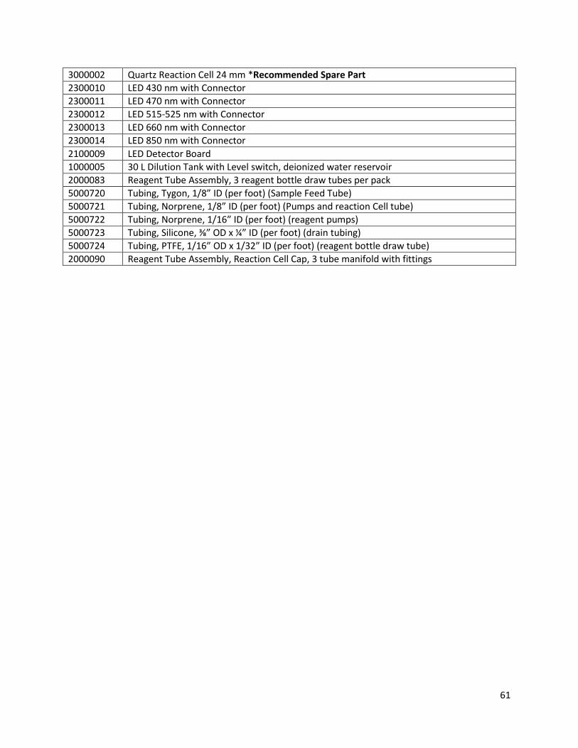
3000002 Quartz Reaction Cell 24 mm *Recommended Spare Part 2300010 LED 430 nm with Connector 2300011 LED 470 nm with Connector 2300012 LED 515-525 nm with Connector 2300013 LED 660 nm with Connector 2300014 LED 850 nm with Connector 2100009 LED Detector Board 1000005 30 L Dilution Tank with Level switch, deionized water reservoir 2000083 Reagent Tube Assembly, 3 reagent bottle draw tubes per pack 5000720 Tubing, Tygon, 1/8” ID (per foot) (Sample Feed Tube) 5000721 Tubing, Norprene, 1/8” ID (per foot) (Pumps and reaction Cell tube) 5000722 Tubing, Norprene, 1/16” ID (per foot) (reagent pumps) 5000723 Tubing, Silicone, ⅜” OD x ¼” ID (per foot) (drain tubing) 5000724 Tubing, PTFE, 1/16” OD x 1/32” ID (per foot) (reagent bottle draw tube) 2000090 Reagent Tube Assembly, Reaction Cell Cap, 3 tube manifold with fittings
61

10.0 ANALYZER SHUT DOWN If the CA-6 Analyzer will be out of service for a period of two weeks or greater, proceed as follows:
1. Empty all reagent containers.
2. Rinse and refill all reagent containers with distilled water.
3. Prime all of the pumps with DI water. (login with 1st level password, press DISPLAY,
MANUAL STEP, ADD REAG 1,2,3,4 for 40 seconds each)
4. Disconnect the sample feed line and fill the fast-loop reservoir (if present) with distilled
water.
5. With the sample inlet tubing attached to a container of distilled water, run the analyzer
for at least 2 cycles.
6. Empty the water from all lines.
7. Put the analyzer in stand-by condition.
8. Turn OFF the power to the analyzer and disconnect the plug from the wall socket.
62
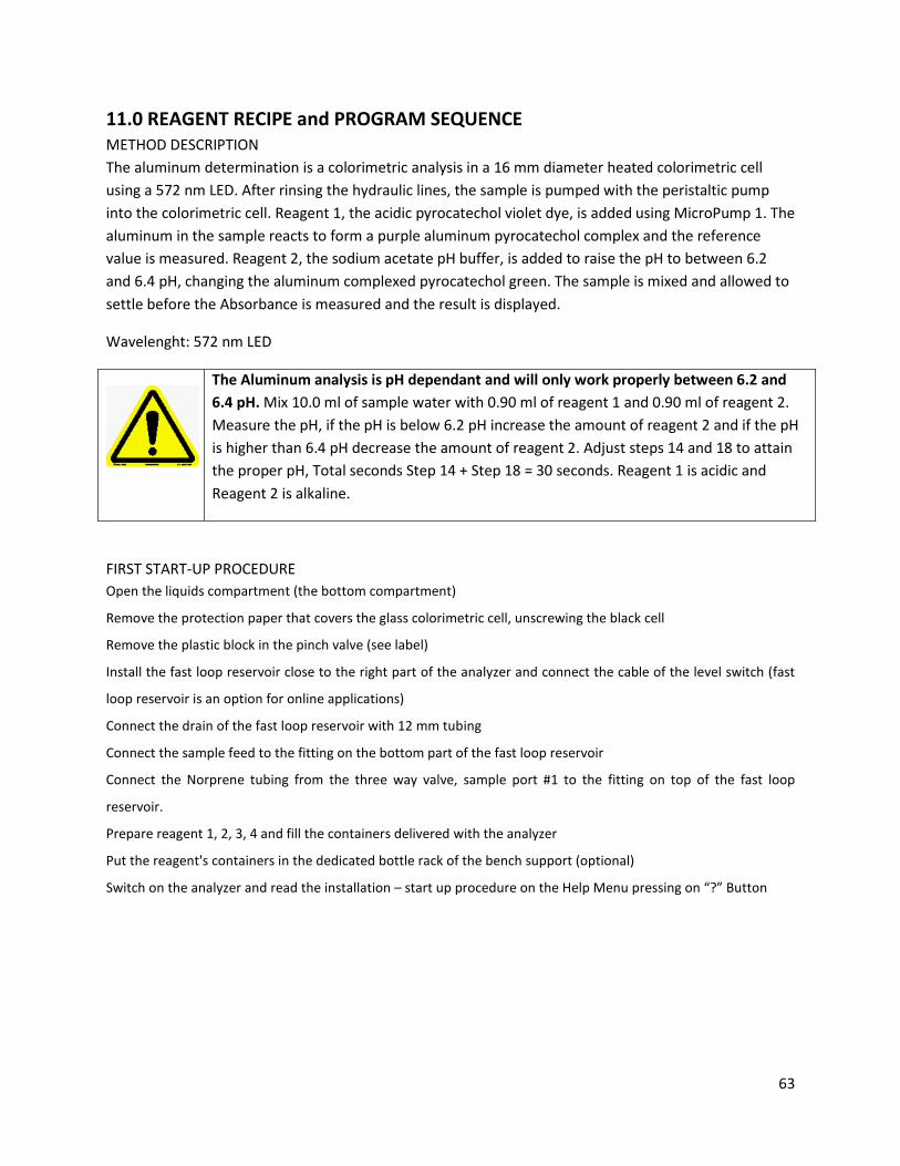
11.0 REAGENT RECIPE and PROGRAM SEQUENCE METHOD DESCRIPTION The aluminum determination is a colorimetric analysis in a 16 mm diameter heated colorimetric cell using a 572 nm LED. After rinsing the hydraulic lines, the sample is pumped with the peristaltic pump into the colorimetric cell. Reagent 1, the acidic pyrocatechol violet dye, is added using MicroPump 1. The aluminum in the sample reacts to form a purple aluminum pyrocatechol complex and the reference value is measured. Reagent 2, the sodium acetate pH buffer, is added to raise the pH to between 6.2 and 6.4 pH, changing the aluminum complexed pyrocatechol green. The sample is mixed and allowed to settle before the Absorbance is measured and the result is displayed.
Wavelenght: 572 nm LED
The Aluminum analysis is pH dependant and will only work properly between 6.2 and 6.4 pH. Mix 10.0 ml of sample water with 0.90 ml of reagent 1 and 0.90 ml of reagent 2. Measure the pH, if the pH is below 6.2 pH increase the amount of reagent 2 and if the pH is higher than 6.4 pH decrease the amount of reagent 2. Adjust steps 14 and 18 to attain the proper pH, Total seconds Step 14 + Step 18 = 30 seconds. Reagent 1 is acidic and Reagent 2 is alkaline.
FIRST START-UP PROCEDURE Open the liquids compartment (the bottom compartment)
Remove the protection paper that covers the glass colorimetric cell, unscrewing the black cell
Remove the plastic block in the pinch valve (see label)
Install the fast loop reservoir close to the right part of the analyzer and connect the cable of the level switch (fast
loop reservoir is an option for online applications)
Connect the drain of the fast loop reservoir with 12 mm tubing
Connect the sample feed to the fitting on the bottom part of the fast loop reservoir
Connect the Norprene tubing from the three way valve, sample port #1 to the fitting on top of the fast loop
reservoir.
Prepare reagent 1, 2, 3, 4 and fill the containers delivered with the analyzer
Put the reagent's containers in the dedicated bottle rack of the bench support (optional)
Switch on the analyzer and read the installation – start up procedure on the Help Menu pressing on “?” Button
63

11.1 Analysis Cycle The programmed sequence for the Analysis Cycle is detailed in the following table. This program assumes that Deionized water is connected to the Left side of the selection valve (Sample Port #1) and the sample is connected to the Right side of the selection valve (Sample Port #2).
Step 30 is user configurable to allow up to 15 minutes (900 seconds) between Analysis Cycles. To enter a time other than 30 seconds go to PROGRAM > SETTINGS > Cycles Wait and enter the new time in seconds.
Step Seconds Function 1 5 DRAIN 2 1 LOOP ON 3 25 RINSE 2 4 1 LOOP OFF 5 5 RINSE 1 6 18 SAMPLE 1 7 5 DRAIN 8 18 SAMPLE 1 9 5 DRAIN
10 6 SAMPLE 1 11 1 LOOP ON 12 6 SAMPLE 1 13 1 LOOP OFF 14 60 WAIT 15 15** ADD REAG 1** 16 30 MIX 17 2 REFERENCE 18 15** ADD REAG 2** 19 100 MIX 20 40 WAIT 21 1 ABSORBANCE 22 2 CALCULATION CH1 23 0 wait 24 2 SAVE DTLOG 25 5 DRAIN 26 18 SAMPLE #1 27 5 DRAIN 28 15 SAMPLE #1 29 0 wait 30 30 WAIT (User adjustable time in seconds)
Step 30 is adjustable by the end user: go to PROGRAM >SETTINGS >Cycle Wait
** May need adjusting to assure measurement between 6.2 pH and 6.4 pH, total time = 30 seconds.
64

11.2 Extra Cycle The EXTRA CYCLE is programmed as a Blank. The EXTRA CYCLE is not activated when shipped. Activate the EXTRA CYCLE in Program > Settings > Cycles Ratio, see section 8.6.3. These programs assume that distilled, de-ionized water is connected to the Left side of the selection valve (Sample Port #1) and the Sample solution is connected to the right side of the selection valve (Sample Port #2).
Step Seconds Function 1 5 DRAIN 2 1 LOOP ON 3 25 RINSE 2 4 1 LOOP OFF 5 5 RINSE 1 6 18 SAMPLE 1 7 5 DRAIN 8 18 SAMPLE 1 9 5 DRAIN
10 6 SAMPLE 1 11 1 LOOP ON 12 6 SAMPLE 1 13 1 LOOP OFF 14 15** ADD REAG 1 15 30 MIX 16 60 WAIT 17 2 REFERENCE 18 15** ADD REAG 2 19 100 MIX 20 40 WAIT 21 1 ABSORBANCE 22 2 BLANK 23 5 DRAIN 24 18 SAMPLE #1 25 5 DRAIN 26 18 SAMPLE #1 27 5 DRAIN 28 15 SAMPLE #1 29 0 Wait 30 30 WAIT (User adjustable time in seconds)
Step 30 is adjustable by the end user: go to PROGRAM >SETTINGS >Cycle Wait
** May need adjusting to assure measurement between 6.2 pH and 6.4 pH, total time = 30 seconds.
65

11.3 TEST DATA
CA6 Analyzer: Aluminum, Pyrocatechol Method Serial Number: CL329 Range (4-20 mA): 0-10 ppm Cell diameter: 16 mm Calibration Standard: 10.0 ppm Dilution Loop: 6.5 cm blue fittings Calibration Factor: 32.28 LED: 572 nm Blank: 0.0039 Number of Reagents: 2 Port#1: De-I water Port#2: Sample Calibration Cycle using Standard Solution
Std 10 ppm Reference Reading Absorbance LED Cal Factor 1 8.72 4.30 0.3074 4.43 32.531 2 8.70 4.35 0.3009 4.43 33.234 3 8.71 4.28 0.3090 4.43 32.362 4 8.69 4.31 0.3042 4.43 32.873 5 8.71 4.37 0.2997 4.43 33.367
Reagents Dosing Test
Reagent 1 (ml) Reagent 2 (ml) 15 sec. 0.851 0.849 60 sec. 3.334 3.318
Linearity test
Standard Solution Absorbance 0 0.000 5 0.1890 10 0.3316
R² = 0.9935
0
0.1
0.2
0.3
0.4
0 2 4 6 8 10 12PPM Aluminum
Absorbance vs ppm
66
11.4 Reagents
DANGER:
Read the precaution and (MSDS) datasheets and wear protective gloves, clothes and glasses before use of chemical products.
11.4.1 REAGENT 1 Reagent 1 is made in two parts and then combined, 80% reagent 1A and 20% reagent 1B.
Reagent 1A
Hydroxylamine hydrochloride, NH2OH · HCl CAS 5470-11-1
16.25 gm
1,10 Phenanthroline, C12H8N2 CAS 66-71-7
0.188 gm
Brij 35, 30%, CAS 9002-92-0
0.1 ml
Concentrated Hydrochloric acid HCl 37% CAS 7467-01-1
22.25 ml
Fill a 1 liter volumetric flask 2/3 full with deionized water. Add 16.25 gm of Hydroxylamine hydrochloride and the 22.25 ml of Hydrochloric acid to the flask while stirring the solution. When the Hydroxylamine hydrochloride has completely dissolved, add the1, 10 Phenanthroline and the Brij 35. Bring the volume to the 1 liter mark with deionized water and allow the solution to cool to room temperature. Check the volume when cool, adjust if necessary.
Reagent 1B
Pyrocatechol Violet, C19H14O7S
CAS 115-41-3
0.112 gm
Formaldehyde 40%, CH2O CAS 50-00-0
0.1 ml
67
Accurately dispense 200 mls of deionized water into a clean beaker. Add the Pyrocatechol Violet and the Formaldehyde, stir until the contents are completely dissolved. Pour the 200 mls of reagent 1B into a 1 liter volumetric flask then add reagent 1A to the 1.00 L mark on the flask, about 800 mls. Pour the mixed solution into the amber bottle labeled REAGENT 1.
11.4.2 REAGENT 2
Sodium Acetate 3-hydrate, CH3COONa· 3H2O
CAS 6131-90-4
200 gm
Sodium Hydroxide, NaOH
CAS 1310-73-2
11 gm
Fill a 1 liter volumetric flask 2/3 full with deionized water. Add 200 gm of Sodium Acetate 3-hydrate and 11 gm of Sodium Hydroxide to the flask while stirring the solution. Continue stirring until the Sodium Acetate 3-hydrate and sodium hydroxide are completely dissolved. Bring the volume to the 1 liter mark and transfer the solution into the amber bottle labeled Reagent 2 supplied with the analyzer.
11.4.3 Standard Solution, 500 ppm Al
Aluminum Potassium Sulfate 12-hydrate, AlK(SO4)2 · 12H2O
CAS 7784-24-9
8.792 gm
Fill a 1 liter volumetric flask 2/3 full with deionized water. Add 8.792 gm of Aluminum Potassium Sulfate 12-hydrate to the flask while stirring the solution. Continue stirring until the Aluminum Potassium Sulfate 12-hydrate is completely dissolved. Bring the volume to the 1 liter mark
Calibration solutions can be made by diluting the 500 ppm Al Standard Solution with an appropriate volume of deionized water, 1ml of 500 ppm Al in 1 liter of water corresponds to a 500 ppb solution of Al.
68

69

●1681 Kettering ● Irvine, CA 92614
● +1-949-336-6060 ● FAX +1-949-336-6064 ● ecdi.com
70