INSTRUCTION MANUAL MJ SERIES - Purdue University
22
Innovations in high voltage power supply technology. GLASSMAN HIGH VOLTAGE INC. 124 West Main Street, PO Box 317 High Bridge, NJ 08829 (908) 638-3800 * FAX (908) 638-3700 * www.GlassmanHV.com INSTRUCTION MANUAL MJ SERIES
Transcript of INSTRUCTION MANUAL MJ SERIES - Purdue University

Innovations in high voltage power supply technology.
GLASSMAN HIGH VOLTAGE INC.124 West Main Street, PO Box 317
High Bridge, NJ 08829(908) 638-3800 * FAX (908) 638-3700 * www.GlassmanHV.com
INSTRUCTION MANUAL
MJ SERIES
102002-038 Rev. B-1\1020\02038B1.P65 12/01/00 1
Glassman High Voltage, Inc. Series MJ
TABLE OF CONTENTSPage
Warranty/User Registration Card ......................................................................................... i
SECTION I - DATA SHEETS .............................................................................................
Features ......................................................................................................... 1aSpecifications, Models, & Outline ............................................................... 1bCE Declaration of Conformity (if applicable) .............................................EMC Directive Addendum (if applicable) ...................................................Specification Control(s) (if applicable) .......................................................
SECTION II - GENERAL INFORMATION .......................................................................
Unpacking and Inspection ............................................................................ 2Correspondence ............................................................................................ 2Safety .......................................................................................................... 3Connectors, Controls, & Indicators .............................................................. 4
AC Power Input Connector .............................................................. 4High Voltage Output Connector ....................................................... 4Remote Control Connector ............................................................... 4Ground Stud ...................................................................................... 5Local Program Control ..................................................................... 5
Installation .................................................................................................... 5Suggested Initial Turn On Procedure ........................................................... 6Control Connector Interface ......................................................................... 7
Interlock ............................................................................................ 7HV (TTL) Enable ............................................................................. 7Voltage Program ............................................................................... 8Current Program ............................................................................... 8Voltage Monitor ............................................................................... 9Current Monitor ................................................................................ 9Common ........................................................................................... 9Ground .............................................................................................. 9+10V Reference ................................................................................ 10X1 - X2 ............................................................................................. 10
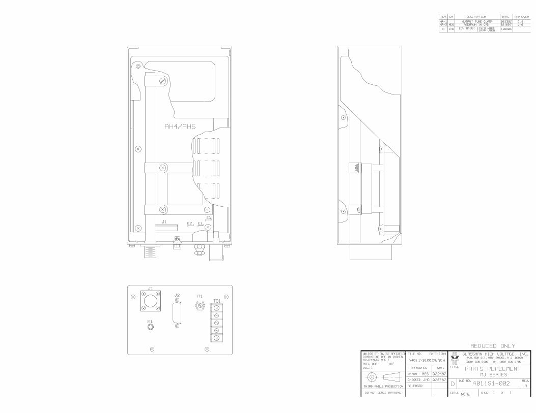
SECTION III - SCHEMATIC AND PARTS PLACEMENT DRAWINGS

MJ Series15 WattRegulatedHigh VoltageDC Modules
PremiumPerformance...Low Cost
Small Size and Weight
Fully compliant with the European harmonized EMI directive, EN50082-2,and with the low voltage (safety) directive, 73/23/EEC.
Line harmonics are within the European harmonized standard,EN61000-3-2 specifications.
Features:Current Regulation Unequalled in a Module of This Price Range.For example, the regulation from short circuit to rated voltage forthe 15 kV, 1 mA model is ± 500 nanoamperes.
Glassman’s “Air Insulated”designs are completely serviceable; this module is not an epoxy block “throw away”.
AC Input: Eliminates the need, and expense of an auxiliary DC power source.
Standard Accessories: Detachable8' shielded output cable, and mating control connector.
Constant Voltage/Current Operation - Standard
Low Stored Energy: Less than 200 millijoules for most models.
“Multi-Mode” operation permits maximum user flexibility.
• Local voltage or current control, user selectable.
• Remote voltage and/or current control via 0 - +10 volt signal.
• Remote voltage and/or current control via potentiometers.
Protection: Overload, short circuit, andarc protection is provided by automaticcurrent regulation and by careful surgelimiting design.
External Interlock Terminals
TTL Enable/Disable
Warranty. Standard power supplies are warranted for three years; OEM and modified power supplies are warranted for one year. A formal warranty statement is available.
Check the specs…
and compare
Designing Solutions for High Voltage Power Supply Applications
GLASSMAN HIGH VOLTAGE INC.124 West Main Street, PO Box 317, High Bridge, NJ 08829-0317(908) 638-3800 • Fax (908) 638-3700 • www.glassmanhv.com
GLASSMAN EUROPE Limited (UK) GLASSMAN JAPAN High Voltage Limited+44 1256 883007 FAX +44 1256 883017 +81 45 902 9988 FAX +81 45 902 2268E-mail: [email protected] E-mail: [email protected]
©Glassman High Voltage, Inc. Printed in the U.S.A. B 12/17/2003
Models from 0-3kVDC through 0-30kVDC; weight < 7.5 lbs.

Output Cable: Detachable, 8 foot.RG8U shielded high voltage coaxialcable is provided.
Controls: A DB15S D-subminiatureconnector, and mating plug, is provided for all control input functions.These include common, + 10 volt
reference, interlock, current monitor,current program, voltage monitor, voltage program, TTL, ground, and local control.
External Interlock: Open off, closed on.
HV Enable/Disable: 0-1.5 V off, 2.5-15 V on.
Specifications(From 5% to 100% rated voltage. Allunits operate down to zero output withvery slight degradation of performance.)
Input: 105-125V RMS or 210-250V RMS(must be specified when ordering),48-420HZ single phase, 0.25 amperes. 3 position terminal block with cover provided. (DC input available for quantity orders - contact factory)
Output: Continuous, stable adjust-ment, from 0 to rated voltage or currentby panel mounted 10-turn potentiome-ter with 0.05% resolution, or by external0 to 10V signals is provided. Voltageaccuracy is 0.5% of setting + 0.2% ofrated. Repeatability is <0.1% of rated.
Stored Energy: 15kV model, < 200 millijoules; 30kV model, < 400 millijoules.
Voltage Regulation: Better than 0.005%line and load.
Ripple: < 0.05% RMS of rated voltage atfull load. Ripple is proportional to loadand decreases linearly to approximately0.01% at no load.
Current Regulation: Better than 0.1%from short circuit to rated voltage at any load condition.
Voltage Monitor: Zero to + 10V DC signal is provided for zero to rated voltage. Accuracy is 0.5% of reading +0.2% of rated.
Current Monitor: Zero to +10V DC signal is provided for zero to rated current. Accuracy, 1% of reading +0.05%of rated current.
Stability: 0.01% per hour. after 1/2 hour warm-up. 0.05% per 8 hours.
Voltage Rise/Decay Time Constant:Using either the HV on/off or remote voltage control, with a 50% load, the output voltage will rise or decay with a typical time constant of 50 milliseconds (100 mS maximum).
Temperature Coefficient: 0.01% per degree C.
Ambient Temperature: -20 degree C to +60 degree C, operating; -40 degreeC to + 85 degree C storage.
Polarity: Available with either positiveor negative polarity with respect to chassis ground.
Protection: Automatic current regulation protects the power supplyagainst all overload conditions, including arcs and short circuits. Fuses, surge limiting resistors, and low energy components provide the ultimate protection.
Designing Solutions for High Voltage Power Supply Applications
GLASSMAN HIGH VOLTAGE INC.124 West Main Street, PO Box 317, High Bridge, NJ 08829-0317(908) 638-3800 • Fax (908) 638-3700 • www.glassmanhv.com
Positive Negative Output Output Output CasePolarity Polarity Voltage Current Cable Size
MJ3P5000 MJ3N5000 0-3 kV 0-5 mA RG-8U AMJ5P3000 MJ5N3000 0-5 kV 0-3 mA RG-8U AMJ10P1500 MJ10N1500 0-10 kV 0-1.5 mA RG-8U AMJ15P1000 MJ15N1000 0-15 kV 0-1 mA RG-8U AMJ20P700 MJ20N700 0-20 kV 0-0.7 mA RG-8U BMJ30P400 MJ30N400 0-30 kV 0-0.4 mA RG-8U B
Place Photo Here
Models:

Glassman High Voltage Inc. Series MJ
\1020\02083\MJC.doc 1 of 3 102002-083MJ Rev. C 11/19/10
Declaration of Conformity
Manufacturers Name: Glassman High Voltage, Inc. Manufacturers Address: PO Box 317 124 West Main Street High Bridge, NJ 08829 USA Manufacturer declares that the MJ Series Power Supplies conform to the following Product Specifications: EMC: EN 61000-6-4:2006, class A EN 61000-6-2:2005 CISPR 11, class A EN 61000-4-2:2005 - 4kV CD, 8kV AD EN61000-4-3:2005- 10V/m EN61000-4-6:2008 - 10V, 80% mod EN 61000-4-5:2005 - +/2kV EN 61000-4-4:2005 - 1kV Signal Cable, EN61000-4-11:2005 – 30/60/90% 2kV AC Mains Means Of Conformity: The product herewith complies with the requirements of the EMC Directive 2004/108/EC based on the use of a Technical Construction File (TCF) in accordance with Article 10.2 of the Directive. Technical Construction File: Prepared by: Mike Ruduski Function: Compliance Engineer Company: AT&T Global Compliance Labs. PO Box 3030 101 Crawfords Corner Road Holmdel, NJ 07733-3030 TCF number: TCF 95-1077MJ Date: December 20, 1995
Updated by: Steve DeClario Function: Chief Engineer
Company: Glassman High Voltage, Inc. PO Box 317 124 West Main Street High Bridge, NJ 08829-0317 USA
TCF number: TCF 95-1077MJ
Declaration of Conformity according to EMC Directive 2004/108/EC

Glassman High Voltage Inc. Series MJ
\1020\02083\MJC.doc 2 of 3 102002-083MJ Rev. C 11/19/10
EMC Compliance Reports: 41643-10-MJ-.GHV, Revision 1 Date: September 27, 2010
MJ15N1000-22EMC Date: October 04, 2010
Test Labs: NTS
36 Gilbert Street South Tinton Falls, NJ 07701
Notified Body: TUV Rheinland EPS B.V. PO Box 15 9822 ZG Niekerk The Netherlands
Signature: Function: Staff Engineer Date: November 19, 2010 EC Representative: Glassman Europe Limited, 21 Campbell Court, Campbell Road, Bramley, Tadley, Hampshire RG265EG, England.

Glassman High Voltage Inc. Series MJ
\1020\02083\MJC.doc 3 of 3 102002-083MJ Rev. C 11/19/10
Declaration of Conformity
Manufacturers Name: Glassman High Voltage, Inc. Manufacturers Address: PO Box 317 124 West Main Street High Bridge, NJ 08829 USA Manufacturer declares that the MJ Series Power Supplies conform to the following Product Specifications: EN 61010-1: Environmental conditions: Indoor use Altitude up to 2000 meters Temperature 5 deg C to 40 deg C Humidity 80% maximum Input Mains Fluctuations +/-10% Installation Category II per IEC1010-1, paragraph 1.4 & annex J Pollution Degree 2 per IEC1010-1, paragraph 3.7.3 Means Of Conformity: The product herewith complies with the requirements of the Low Voltage Directive 73/23/EEC based on design analysis and testing in accordance with Article 13, Annex IV of Directive 93/68/EEC, amending Directive 73/23/EEC. Signature: Function: Staff Engineer Date: February 10, 1997 EC Representative: Glassman Europe Limited, 21 Campbell Court, Campbell Road, Bramley, Tadley, Hampshire RG265EG, England.
Declaration of Conformity according to Low Voltage Directive 73/23/EEC
Glassman High Voltage Inc. EMC Directive Addendum
102002-081 Rev B 1 of 1 \1020\02081_B.doc 15 Jun 2011
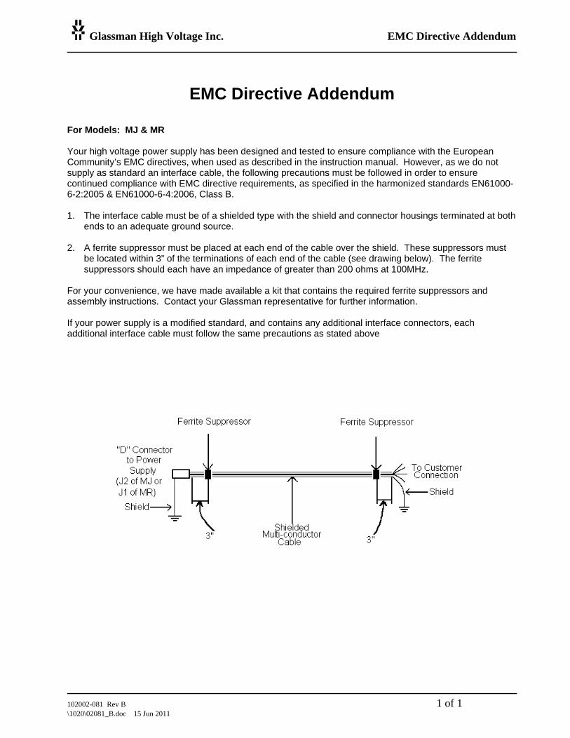
EMC Directive Addendum For Models: MJ & MR Your high voltage power supply has been designed and tested to ensure compliance with the European Community’s EMC directives, when used as described in the instruction manual. However, as we do not supply as standard an interface cable, the following precautions must be followed in order to ensure continued compliance with EMC directive requirements, as specified in the harmonized standards EN61000-6-2:2005 & EN61000-6-4:2006, Class B. 1. The interface cable must be of a shielded type with the shield and connector housings terminated at both
ends to an adequate ground source. 2. A ferrite suppressor must be placed at each end of the cable over the shield. These suppressors must
be located within 3” of the terminations of each end of the cable (see drawing below). The ferrite suppressors should each have an impedance of greater than 200 ohms at 100MHz.
For your convenience, we have made available a kit that contains the required ferrite suppressors and assembly instructions. Contact your Glassman representative for further information. If your power supply is a modified standard, and contains any additional interface connectors, each additional interface cable must follow the same precautions as stated above
102002-038 Rev. B-1\1020\02038B1.P65 12/01/00 2
Glassman High Voltage, Inc. Series MJ
SECTION II - GENERAL INFORMATION
UNPACKING AND INSPECTION
First inspect package exterior for evidence of rough handling in transit. If none,proceed to unpack ... carefully. After removing the supply from its shipping con-tainer, inspect it thoroughly for damage.
IMPORTANT! In cases of damage due to rough handling in transit, notify the carrierimmediately if damage is evident from appearance of package. Do not destroy orremove any of the packing material used in a damaged shipment. Carrier companieswill usually not accept claims for damaged material unless they can inspect thedamaged item and its associated packing material. Claims must be made promptly -certainly within five days of receipt of shipment.
CORRESPONDENCE
Each Glassman power supply has an identification label on the chassis that bears itsmodel and serial number. When requesting engineering or applications information,reference should be made to this model and serial number, as well as to the compo-nent symbol number(s) shown on the applicable schematic diagram, if specific com-ponents or circuit sections are involved in the inquiry.
GLASSMAN HIGH VOLTAGE, INC.PO Box 317
124 West Main StreetHigh Bridge, NJ 08829
TEL. 908-638-3800FAX. 908-638-3700
E-MAIL [email protected]
102002-038 Rev. B-1\1020\02038B1.P65 12/01/00 3
Glassman High Voltage, Inc. Series MJ
SAFETYThis symbol, wherever it appears on the supply, alerts you to thepresence of uninsulated dangerous voltages - voltages that may besufficient to constitute a risk of electrical shock.
This symbol, wherever it appears on the supply, alerts you to impor-tant operating and maintenance instructions in the accompanyingliterature. Read the manual.
TERMS IN THIS MANUAL
CAUTION statements identify conditions or practices that could resultin damage to the equipment or other property.
WARNING! statements identify conditions or practices that couldresult in injury or loss of life.
WARNING!To avoid the risk of shock, wait at least 15 seconds before disconnecting the HVcable from the supply.
To avoid the risk of shock and personal injury, do not remove the productcovers. No user serviceable components inside.
Upon loss of protective ground connection(s), all accessible conductive parts canrender an electric shock.
Use only a power cord rated greater than the input current rating of the unit.Use only a cord in good condition.
To avoid explosion, do not operate this product in an explosive atmosphere.
If liquid is spilled on the supply, shut it off immediately and disconnect it fromthe AC mains.
Always maintain adequate supply ventilation. All ventilation openings mustremain free from obstruction.

102002-038 Rev. B-1\1020\02038B1.P65 12/01/00 4
Glassman High Voltage, Inc. Series MJ
CONNECTORS, CONTROLS, & INDICATORS (Refer to the Interface Diagram inSection III for Figures 1-10)
TB1 AC POWER INPUT
WARNING! The ground terminal of TB1 should always be connected to theAC mains ground or other good earth ground.
This unit is a component type of power supply, and as such, is designed for perma-nent mounting within an equipment enclosure that will provide adequate fire andshock protection. This supply is not designed for "bench top" operation. Check tosee that your input line voltage and frequency matches the rating of the supply beforeapplying power. The line cord wires should be connected as follows (see Figures 8 &9):
TB1-1 Line (Brown)TB1-2 Line/Neutral (Blue)TB1-3 Ground (Green/Yellow)
For CE compliant supplies used in Europe:Please refer to the Declaration of Conformity located elsewhere in this manualfor installation environment conditions required to conform to 73/23/EEC (LowVoltage Directive).
J1 HIGH VOLTAGE OUTPUT CONNECTOR
WARNING! Do not make or remove connections to this connector or any otherconnector until AC power is off and the DC output has discharged.
This is the high voltage output of the supply (see Figures 7, 8, & 9). Engage theconnector as follows: Insert the high voltage output cable provided into the recep-tacle; spring action should be felt as the probe reaches the bottom. Hold the cablepressed down against the spring and screwthe locking nut onto the receptacle.
J2 REMOTE CONTROL CONNECTOR
WARNING! Do not make or remove connections to this connector or any otherconnector until AC power is off and the DC output has discharged.
This connector provides inputs and outputs for the remote control functions. For a

102002-038 Rev. B-1\1020\02038B1.P65 12/01/00 5
Glassman High Voltage, Inc. Series MJ
description of each of these signals and their application, see the Control ConnectorInterface portion of Section II (page 7) and Figures 1-10 of the INTERFACE DIA-GRAM in Section III. Pin-outs are as follows:
1 X1 (NOT USED ON STANDARD MODELS)2 COMMON3 COMMON4 COMMON5 +10V REFERENCE6 +10V REFERENCE7 X2 (NOT USED ON STANDARD MODELS)8 INTERLOCK9 CURRENT MONITOR10 HV (TTL) ENABLE11 CURRENT PROGRAM12 GROUND13 VOLTAGE PROGRAM14 VOLTAGE MONITOR15 LOCAL CONTROL
E1 GROUND STUD
WARNING! Do not operate unit without good external earth ground connectedto this point.
This is the main grounding terminal for the supply (see Figures 7, 8, & 9).
LOCAL PROGRAM CONTROL
This 10-turn control provides a 0 to +10V signal for local current or voltage program-ming. Clockwise rotation increases output. A locking nut is provided to secure thesetting.
INSTALLATION
This unit is a component type of power supply, and as such, is designed for perma-nent mounting within an equipment enclosure that will provide adequate fire andshock protection. This supply is not designed for "bench top" operation.
102002-038 Rev. B-1\1020\02038B1.P65 12/01/00 6
Glassman High Voltage, Inc. Series MJ
Refer to the OUTLINE AND INSTALLATION drawing in Section III for mechanicalmounting specifications and dimensions. Care should be taken when mounting thissupply not to block or otherwise impede airflow at inlet and exhaust areas.
WARNING!
NEVER ATTEMPT TO OPERATE THIS UNIT WITHOUT A GOOD EARTHGROUND CONNECTED TO THE GROUND STUD, E1. THE GROUNDTERMINAL OF THE LINE CORD CONNECTED TO TB1 SHALL ALSO BEGROUNDED.
READ AND FULLY UNDERSTAND THE OPERATING INSTRUCTIONSBEFORE APPLYING POWER TO THIS UNIT.
THIS EQUIPMENT EMPLOYS VOLTAGES THAT ARE DANGEROUS.EXTREME CAUTION MUST BE EXERCISED WHEN WORKING WITHTHIS EQUIPMENT.
DO NOT HANDLE THE LOAD OR EXPOSED HIGH VOLTAGE TERMINA-TIONS, OR ATTEMPT TO MAKE OR REMOVE ANY CONNECTIONS TOTHE SUPPLY UNTIL THE LOAD AND/OR SUPPLY HAS BEEN DIS-CHARGED (GROUNDED). AN UNLOADED SUPPLY MAY TAKE UP TO 15SECONDS TO FULLY DISCHARGE.
ALWAYS MAKE CERTAIN THAT THE RETURN SIDE OF THE LOAD ISCONNECTED TO COMMON OR GROUND.
SUGGESTED INITIAL TURN ON PROCEDURE (Refer to the Interface Diagram inSection III for Figures 1-10)
WARNING: This procedure should only be attempted by qualified personnel whoare knowledgeable in methods of safely testing and operating high voltage powersupplies and related high voltage equipment.
1. Check the AC input ratings of the power supply as indicated on the modellabel located on the side of the unit. Make certain that the AC power source isadequate and fusing is provided.
2. Make connections to plug P2 as shown in Figure 9. Connect high impedance

102002-038 Rev. B-1\1020\02038B1.P65 12/01/00 7
Glassman High Voltage, Inc. Series MJ
digital voltmeters or 1mA movement analog meters to the CURRENT andVOLTAGE MONITOR outputs (0 to +10V = 0 to supply rating). Connect P2to J2.
3. Be sure the supply is properly grounded. Connect the high voltage outputcable and a grounded return lead to a load as shown in Figure 9. Use agrounded resistive load of known value with adequate voltage and powercapability for the supply under test. Isolate the load from possible contactwith other objects and personnel.
4. Rotate the LOCAL CONTROL fully counter-clockwise.
5. Connect the AC input cable to TB1 and the power source. Apply AC inputpower to the supply.
6. Rotate the LOCAL CONTROL clockwise until the VOLTAGE MONITORindicates the desired output voltage. The CURRENT MONITOR shouldindicate expected output current as calculated by I=E/R.
7. Remove the AC input power to shut down the supply.
WARNING! DO NOT HANDLE THE LOAD OR EXPOSED HIGH VOLT-AGE TERMINATIONS, OR ATTEMPT TO MAKE OR REMOVE ANYCONNECTIONS TO THE SUPPLY UNTIL THE LOAD AND/OR SUPPLYHAS BEEN DISCHARGED (GROUNDED). AN UNLOADED SUPPLY MAYTAKE UP TO 15 SECONDS TO FULLY DISCHARGE.
CONTROL CONNECTOR INTERFACE (Refer to the Interface Diagram in Section IIIfor Figures 1-10)
J2-8 INTERLOCK
This terminal must be connected to COMMON to enable the supply. If an externalinterlock is desired, a switch can be connected between the INTERLOCK pin and anyCOMMON pin. This switch must be closed to make the supply operable. When theexternal switch is open, the supply is disabled. If no external interlock is required,this pin can be connected directly to COMMON with a wire jumper (see Figures 1, 8,& 9).
J2-10 HV (TTL) ENABLE

102002-038 Rev. B-1\1020\02038B1.P65 12/01/00 8
Glassman High Voltage, Inc. Series MJ
This terminal must be connected to a 2.5 - 10V source, positive with respect to COM-MON, to enable the supply. A 0 - 1.5V signal at this input will disable the supply.When no external control is required, this input can be jumpered to any +10V REF-ERENCE pin (see Figures 2, 8, & 9).
J2-13 VOLTAGE PROGRAMJ2-15 LOCAL CONTROL
A 0 - 10V positive signal, with respect to COMMON, will program the output voltageproportionally from zero to full output. This input can be programmed in severalways (see Figures 3, 8, & 9):
* A user supplied 0 - +10V signal.
* A user supplied potentiometer (5- 50k ohms, 10k nominal) can be connectedbetween any +10V REFERENCE pin and any COMMON pin, with the wiperconnected to the VOLTAGE PROGRAM pin.
* The 0 - +10V signal supplied by the LOCAL CONTROL pin and adjusted bythe LOCAL CONTROL.
* The VOLTAGE PROGRAM input may be jumpered to any +10V REFER-ENCE pin for a fixed output at the maximum rated voltage.
J2-11 CURRENT PROGRAMJ2-15 LOCAL CONTROL
A 0-10V positive signal, with respect to COMMON, will program the maximumoutput current proportionally from zero to full rated output. This input can be pro-grammed in several ways (see Figures 4, 8, & 9):
* A user supplied 0 - +10V signal.
* A user supplied potentiometer (5-50k ohms, 10k nominal) can be connectedbetween any +10V REFERENCE pin and any COMMON pin, with the wiperconnected to the CURRENT PROGRAM pin.
* The 0 - +10V signal supplied by the LOCAL CONTROL pin and adjusted bythe LOCAL CONTROL.
* The CURRENT PROGRAM input may be jumpered to any +10V REFER-ENCE pin for a fixed output at the maximum rated current.

102002-038 Rev. B-1\1020\02038B1.P65 12/01/00 9
Glassman High Voltage, Inc. Series MJ
J2411 VOLTAGE MONITOR
A 0-10V signal, positive with respect to COMMON, and in direct proportion to theoutput current, is available at this pin. A 10k ohm, 1% resistance is in series with thisoutput to protect the internal circuitry. An instrument with a high input impedance(>10M), such as a digital voltmeter, should be used to monitor this output. This willminimize the voltage drop across the 10k resistance. Alternately, a 1mA analogmeter can be used, since the 10k resistor provides the proper impedance to drive themeter to full scale at 10V (see Figure 5).
J2-9 CURRENT MONITOR
A 0-10V signal, positive with respect to COMMON, and in direct proportion tooutput current, is available at this pin. A 10k ohm, 1% resistance is in series with thisoutput to protect the internal circuitry. An instrument with a high input impedance(>10M), such as a digital voltmeter, should be used to monitor this output. This willminimize the voltage drop across the 10k resistance. Alternately, a 1mA analogmeter can be used, since the 10k resistor provides the proper impedance to drive themeter to full scale at 10V (see Figure 6).
J2-2, 3 & 4 COMMON
These pins are for instrumentation/measurement return. Normally, the COMMON isoperated at ground potential by means of a jumper to GROUND. In this condition,instrument returns and the load return may be connected to either COMMON orGROUND. If desired, the user may remove this jumper and allow the COMMON to“float”. This may be done for isolation or for the purpose of inserting a currentmonitoring device. When COMMON is floating, it is clamped internally by a bidi-rectional zener diode. Thus the inserted drop should not exceed 15.0V or erroneousreadings will be obtained. In this configuration, the load return must be connected toGROUND and all instrument/programming returns must be connected to COMMON.In addition, instrument returns to COMMON must be isolated from GROUND (seeFigures 7, 8, & 9).
J2-12 GROUND
This is the instrumentation ground connection. This terminal should not be used asthe main connection to earth ground. Use the main ground terminal “E1” for thatpurpose. This terminal is normally connected one of the COMMON pins unless afloating COMMON is required (see J1- 5, 8, etc.). If a floating COMMON is em-ployed, this connection (or E1) can be used as the load return (see Figures 7, 8, & 9).
Scott.Jarmicki
Cross-Out
Scott.Jarmicki
Inserted Text
J2-14

102002-038 Rev. B-1\1020\02038B1.P65 12/01/00 10
Glassman High Voltage, Inc. Series MJ
J2-5 & 6 +10V REFERENCE
The signal available at these pins is an ultra-stable, positive with respect to COM-MON, 10V reference voltage, supplied for user programming applications. Thecombined maximum current drawn should be limited to 5mA (see Figures 3, 4, 8, &9).
J2-1 X1J2-7 X2
These terminals are reserved for special options or future expansion of features.
NOTE REGARDING INTERFACE DIAGRAM:
Figure 8 is just one example of the many wiring con-figurations possible.
Figure 9 shows the minimum number of connections tocompletely enable the supply. In this configuration, theoutput voltage is adjusted by the LOCAL CONTROLand the current limit is fixed at the maximum ratedoutput current. No external INTERLOCK or HVENABLE signals are required.