Instruction Manual - Meade Instruments Telescopes, Solar ... · Instruction Manual Meade Model 4504...
48
Instruction Manual Meade Model 4504 4.5" (114mm) Equatorial Reflecting Telescope With Starfinder Electronic Hand Controller ENTER GO TO MODE MEADE ENTER GO TO MODE ? STARFINDER Meade Instruments Corporation
Transcript of Instruction Manual - Meade Instruments Telescopes, Solar ... · Instruction Manual Meade Model 4504...

Instruction ManualMeade Model 4504 4.5" (114mm) Equatorial Reflecting TelescopeWith Starfinder Electronic Hand Controller
ENTER GO TOMODE
MEADE
ENTER GO TOMODE
SPEED?
STARFINDER
Meade Instruments Corporation

WARNINGNEVER USE A MEADE® TELESCOPE TO LOOK AT THE SUN!LOOKING AT OR NEAR THE SUN WILL CAUSE INSTANT ANDIRREVERSIBLE DAMAGE TO YOUR EYE. EYE DAMAGE IS OFTENPAINLESS, SO THERE IS NO WARNING TO THE OBSERVER THATDAMAGE HAS OCCURRED UNTIL IT IS TOO LATE. DO NOT POINTTHE TELESCOPE OR ITS VIEWFINDER AT OR NEAR THE SUN. DONOT LOOK THROUGH THE TELESCOPE OR ITS VIEWFINDER AS ITIS MOVING. CHILDREN SHOULD ALWAYS HAVE ADULTSUPERVISION WHILE OBSERVING.
How This Manual is OrganizedThis manual is divided into three major sections.
Part One, "The Basics," presents several "Lessons" that will teach you how toassemble and use your telescope and Starfinder. If you follow all the Lessons in thissection, you will become familiar with the basic operation of your telescope and theStarfinder handbox by the end of Part One. This section covers the following proce-dures:
Lesson 1: Unpacking and Assembly.
How to unpack and assemble the basic telescope and tripod unit.
Lesson 2: Balancing the Telescope.
How to balance the telescope.
Lesson 3: Aligning the Viewfinder.
How to align the viewfinder and insert the eyepiece into the focuser.
Lesson 4: Observing by Moving the Telescope Manually.
How to focus an eyepiece. How to move your telescope manually to makeobservations.
Lesson 5: Observing using Starfinder's Arrow keys.
How to install the motor drives. How to change the slew speeds. How toobserve using Starfinder's Arrow keys.
Lesson 6: Tracking Objects.
How to Polar align your telescope. How to observe using automatic tracking.
Lesson 7: Observing using Starfinder's Go To Capabilities.
How to initialize Starfinder and train the drive. How to move around inStarfinder's menus. How to observe using Starfinder and how to take aGuided Tour of the night sky.
Part Two, "Starfinder's Controls and Menus," provides more information aboutStarfinder's databases and menus.
Part Three, "Caring for Your Telescope," provides information that explains how toproperly maintain your telescope.
The Appendices provide advanced information about your telescope, explain howobjects move through the skies, and teach how to locate objects not listed in theStarfinder database.
® The name "Meade" and the Meade logo are trademarks registered with the U.S. Patent Office and in principal countriesthroughout the world. All rights reserved.
© 2000 Meade Instruments Corporation

page 3
TABLE OF CONTENTS
PART ONE: The Basics
Lesson 1: Unpacking and Assembly ....................................................................5How to Assemble Your Telescope......................................................................8
Lesson 2: Balancing the Telescope ....................................................................10Lesson 3: Aligning the Viewfinder ......................................................................10Lesson 4: Observing by Moving the Telescope Manually ..................................11
Observe the World Around You........................................................................13Lesson 5: Using Starfinder's Arrow Keys ............................................................13
Motor Drive System and Starfinder Handbox Installation ................................13Activate the Arrow Keys ..................................................................................14Slew Speeds ....................................................................................................14Observe the Moon............................................................................................15
Lesson 6: Tracking Objects ................................................................................15To Polar Align the Telescope............................................................................15Observe a Star Using the Automatic Tracking Feature....................................16
Lesson 7: Using Starfinder's GO TO Capabilities ..............................................16Moving Through Starfinder's Menus ................................................................16Initializing Starfinder ........................................................................................17Training the Drive ............................................................................................19Align Your Telescope Using Starfinder ............................................................20Check Mount ....................................................................................................20Go To Saturn ....................................................................................................21Using the Guided Tour ....................................................................................21Some Observation Tips....................................................................................22
PART TWO: Starfinder Controls and Menus
Starfinder Controls ..............................................................................................23How Starfinder's Menus Work ............................................................................26Starfinder Navigation Exercise ............................................................................26Starfinder Menus..................................................................................................28
Object Menu ....................................................................................................28Event Menu ......................................................................................................29Glossary Menu ................................................................................................29Utilities Menu....................................................................................................30Setup Menu......................................................................................................31
PART THREE: Caring for Your Telescope
Cleaning ..............................................................................................................33Mount and Tripod Adjustments............................................................................33Collimation (Alignment) of the Optics ..................................................................34Specifications ....................................................................................................37Appendix A: Calculating Eyepiece Power ..........................................................38Appendix B:Terrestrial Viewing, Celestial Movement, & Polar Alignment ..........39Appendix C: Using Starfinder to Enter Celestial Coordinates ............................42Appendix D: Helpful Charts ................................................................................43Appendix E: Basic Astronomy ............................................................................44
Objects in Space ............................................................................................44A Roadmap to the Stars ..................................................................................46Star Locator ....................................................................................................46
page 4
1
2
3
4
5
7
8
96 10 11
12
13 14
15
16
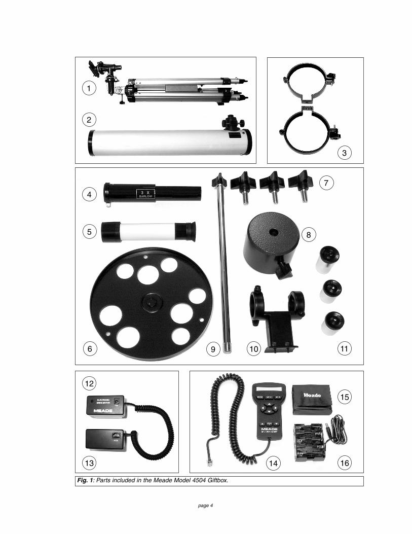
Fig. 1: Parts included in the Meade Model 4504 Giftbox.

page 5
PART ONE: The BasicsLESSON 1: Unpacking and AssemblyAs you unpack your telescope, carefully note the following parts. The bolded numbersin parentheses on this page refer to the photos on page 4.
Telescope Assembly
• Equatorial mount (1) with a pre-attached heavy duty, continuouslyadjustable aluminum tripod with leg braces
• 3 tripod leg lock knobs (7)• Complete optical tube assembly (2) including a 4.5" (114mm) diameter
primary mirror with dust cover and a 0.965" rack-and-pinion focuser withdust cap
• 2 Cradle rings (3) with attached lock knobs• Counterweight (8) and counterweight shaft (9)• 5 x 24 viewfinder with rubber eyecup (5) and viewfinder bracket (10)
Motor Assembly
• Dual electronic motor drive assembly: The Right Ascension (R.A.)electronic motor drive (12) has a connector for the battery pack, marked"15v." The Declination (Dec) electronic motor drive (13) has a connectorfor the Starfinder handbox, marked "HBX." The motors are connectedwith a coiled cord.
• Starfinder handbox (14)• Battery pack (16) and battery pack case (15) with adhesive backing
Accessories
• 3 Eyepieces (11) (0.965" optical diameter): SR 4mm, H 12.5mm, H 25mm
• 3x Barlow lens (4)• Accessory shelf with mounting knob (6)• 2 Hex Keys, 1.5mm, 5mm (not depicted)• Astronomical software (not depicted)
You will need a #1 or #2 Phillips screwdriver to assemble this telescope.
Key to the photos, Fig. 1, page 4.
1. Tripod assembly with equatorial mount2. Optical tube3. Cradle rings4. 3x Barlow lens5. Viewfinder tube6. Accessory shelf7. Tripod leg adjustment knobs8. Counterweight9. Counterweight shaft
10. Viewfinder bracket11. Eyepieces 12. R.A. motor drive13. Dec motor drive 14. Starfinder handbox15. Battery pack case16. Battery pack

page 6
1
2
6
5
4
7
8
3
16
10
11
12
9
14
13
15
Fig. 2a: The Meade Model 4504 4.5" Equatorial Reflecting Telescope.
1. Equatorial mount
2. Optical tube assembly
3. Cradle rings
4. Viewfinder bracket
5. Viewfinder rubber eyepiece
6. 5 x 24 viewfinder
7. Viewfinder bracket thumbscrews
8. Telescope front dust cover
9. Dec setting circle
10. Counterweight
11. Counterweight shaft
12. Safety washer/thumbscrew
13. Counterweight lock
14. Latitude dial
15. R.A. setting circle
Key to Figures 2a, 2b, and 2c
16. Latitude adjustment knob
17. Focuser, Focus knobs
18. Eyepiece thumbscrew
19. Eyepiece
20. Cradle ring lock knobs
21. Optical tube saddle plate
22. Dec motor drive assembly
23. Latitude lock
24. Azimuth lock
25. R.A. motor drive assembly
26. R.A. lock
27. Dec lock
28. Tripod legs brace support
29. Tripod legs lock knobs
30. Accessory shelf

page 7
23
18
21
22
27
25
19
20
20
24
26
17
28
29
30
28
29
NOTE: The coiled cord thatconnects to the two motordrives has been omittedfrom the illustration for thesake of clarity.
Fig. 2b: The Meade Model 4504 4.5" Equatorial Reflecting Telescope.
Fig. 2c: The Meade Model 4504 4.5" Equatorial Reflecting Telescope.

page 8
How to Assemble Your TelescopeThe giftbox contains the optical tube assembly and the tripod with the equatorialmount. The accessories are located within compartments custom-cut into the styro-foam block inserts. Refer to Figures 1, 2a, 2b, and 2c for images of the parts and theoverall assembly of the 4504 telescope.
1. Remove the components from the giftbox: Remove and identify the telescope’sstandard equipment. For a listing of parts that are included in the giftbox, seepages 4 and 5. When removing the tripod from the giftbox, hold the assemblyparallel (horizontal) to the ground or the inner tripod leg extensions will slide outas they are not locked in place.
2. Install the lock knobs on the tripod: Place the tripod in a horizontal position onthe floor before performing this step. The three tripod lock knobs (7, Fig. 1) havebeen removed from the bottom section of each tripod leg to insure safe arrival ofthe tripod assembly. To install, thread each tripod lock knob into the threaded holelocated at the right side of each of the three gray-colored castings at the bottomof each tripod leg. See Fig. 3, and 29, Fig. 2c. Tighten the tripod lock knob to a"firm feel" only to avoid damage to the tripod caused by overtightening.
3. Stand the tripod: Hold the mount for support (the mount will be loose) and standthe tripod in a vertical position. Slide the cardboard sheath upward to allow it tocome free when the tripod legs are spread out during the next step.
4. Adjust the tripod legs. Spread the tripod legs as far as they will open, so that theleg braces (28, Fig. 2c) are taut. Should one of the leg braces slip out of the centertriangle fastener, reposition the brace and slide it back into the triangle fastener.
5. Attach the accessory shelf to the tripod: Remove the mounting knob from theround accessory shelf (6, Fig. 1). Place the accessory shelf on top of the centertriangle leg brace fastener so that the threaded stud protruding from the bottom ofthe shelf (Fig. 4) passes through the hole in the center of the triangle fastener.Next, thread the mounting knob shaft into the threaded stud. Tighten to a firm feel.
6. Attach the counterweight to the counterweight shaft: Look through the hole inthe counterweight and note the pin blocking the hole (Fig. 5). Tilt thecounterweight slightly and the pin moves out of position, clearing the hole. If thepin does not move, slightly unscrew the counterweight lock knob (Fig. 5) until thepin moves. Holding the counterweight (8, Fig. 1) firmly in one hand, tilt thecounterweight to move the pin from the hole and slip the counterweight onto thecounterweight shaft (9, Fig. 1). Tighten the counterweight lock knob (Fig. 5) to afirm feel.
7. Attach the counterweight assembly to the mount: Attach the counterweightshaft assembly by supporting the counterweight firmly in one hand, whilethreading the counterweight shaft into the base (Fig. 6) of the Declination axis ofthe telescope’s equatorial mount with the other. Once firmly attached, loosen thecounterweight lock knob, slide the counterweight to the midpoint of thecounterweight shaft, and re-tighten the lock knob firmly in place (Fig. 5).
NOTE: If the counterweight ever slips, the secured threaded safetywasher/knob (12, Fig. 2a) prevents the counterweight from sliding entirelyoff the shaft. The safety washer/knob is pre-attached at the factory. Makesure that this safety washer/knob always remains in place.
Fig. 3: Tripod leg lockknob.
Fig. 5: Counterweightand pin.
Lock knob
Pin
Fig. 4: Accessoryshelf installation.
Fig. 6: Attachcounterweightassembly to themount.
Thread shaftinto base
Threadedhole
Slidinginner leg
Leg lock knob

page 9
8. Tilt the assembly: Unlock the R.A. lock (26, Fig. 2b) and the Dec lock (27, Fig.2b) so that the telescope turns freely on both axes. Tilting these axes makes iteasier for you to perform the following steps. Turn the latitude adjustment knob(16, Fig. 2a) until approximately 1 1/2 inches of thread is showing. This will adjustthe equatorial mount (1, Fig. 2a) to a comfortable angle for tube attachment.
9. Attach the cradle rings to the saddle plate: Remove the attachment screwsfrom the saddle plate (these screws come attached in the threaded screw holes ofthe saddle plate, 1, Fig. 7). Position the threaded screw hole of a cradle ring (4,Fig. 7) under one of the threaded screw holes of the saddle plate (1, Fig. 7).Thread one of the attachment screws (5, Fig. 7) through the bottom side of thecradle ring and through the saddle plate, tightening it with the provided 5mm hexwrench (so that it is only "fingertight," that is, just loose). Repeat for the secondcradle ring. Remove the cradle ring lock knobs (20, Fig. 2b) and open the cradlerings.
10. Position optical tube: While firmly holding the optical tube (2, Fig. 2a), position itonto the cradle rings (3, Fig. 2a) with the mid-point of the optical tube’s length lyingroughly in the center of the saddle plate. Point the tube so that the front end (thisend comes shipped with the dust cover (8, Fig. 2a) over it) is oriented as depictedin Fig. 2a. Then close the cradle rings (3, Fig. 2a) over the optical tube and looselytighten one of the cradle ring lock knobs (20, Fig. 2b) just to hold the tube in placeso you can perform the next step of this procedure.
11. Secure the optical tube: Tighten the cradle ring attachment hex screws to a firmfeel. Then tighten both cradle ring lock knobs (20, Fig. 2b) to a firm feel; do notovertighten these knobs as you may wish loosen them frequently in order to rotatethe optical tube and position the eyepiece (19, Fig. 2b) in a more comfortableobserving position. This adjustment may be performed several times in oneobserving session, if so desired.
12. Attach viewfinder: The viewfinder holder has two restrained screws, i.e., theycannot be removed from the holder. Position the two screws over the threadedholes in the viewfinder mounting plate and tighten the screws using a #1 or #2Phillips screwdriver. It does not matter which way you orient the holder lengthwise.Loosen the viewfinder's thumbscrews (7, Fig. 2a), but do not remove them.Remove the viewfinder tube's rubber eyecup (5, Fig. 2a) and slide the tube (6, Fig.2a) through the bracket rings of the holder. Then center the tube by adjusting thethumbscrews (7, Fig. 2a) on each bracket ring. Re-attach the eyecup. Make surethat the viewfinder is oriented so that the rubber eyecup is pointing away from frontend of the optical tube (5, Fig. 2a).
13. Insert the eyepiece: Lift to remove the dust cap from the focuser assembly (17,Fig. 2b). Put the dust cap aside in a safe place and replace it when you havefinished observing to protect the eyepiece assembly. Loosen the eyepiecethumbscrews (18, Fig. 2b) and insert the H 25mm eyepiece (Fig. 8) into thefocuser. Tighten the focuser thumbscrews to secure the eyepiece.
14. Adjust the height of the tripod: Adjust the height of the tripod by loosening thetripod lock knobs (29, Fig. 2c) and extending the sliding inner section of eachtripod leg to the desired length; then tighten each knob. Adjust the tripod to aheight that is comfortable for viewing.
Lesson 5 presents a procedure that explains how to attach the motor driveassemblies. However, that procedure is not necessary at this time. The followinglesson demonstrates how to balance your telescope.
Fig. 7: Attach cradlerings to the saddle platewith attachment screws.
1. Threaded screw hole(saddle plate)2. Saddle plate3. Cradle ring4. Threaded screw hole(cradle ring)5. Attachment screw
1 2 1
3
5
4
Fig. 8: Insert eyepieceinto the focuserassembly.
Eyepiece
Thumb-screwFocuser

page 10
LESSON 2: Balancing the TelescopeIn order for the telescope to be stable on the tripod and also for it to move smoothly,it must be balanced. To balance the telescope, you will unlock the Right Ascension orR.A. lock (26, Fig. 2b and Fig. 9a). When this axis is unlocked, the telescope pivotsmore or less horizontally on the mount. This is called the R.A. axis. Later in the pro-cedure, you will also unlock the Declination or Dec lock (27, Fig. 2b and Fig. 9a).When unlocked, the telescope pivots more or less vertically on the mount. This iscalled the Dec axis. Most of the motion of the telescope takes place by moving aboutthese two axes, separately or simultaneously. To obtain a fine balance of the tele-scope, follow the method below:
1. Firmly hold the optical tube secure so that it cannot accidentally swing freely.Loosen the R.A. lock (26, Fig. 2b). The optical tube now turns freely about theR.A. axis. Rotate the telescope so that the counterweight shaft (11, Fig. 2a) isparallel (horizontal) to the ground (Fig. 9b).
2. Unlock the counterweight lock knob (13, Fig. 2a) and slide the counterweight (10,Fig. 2a) along the counterweight shaft until the telescope remains in one positionwithout tending to drift down in either direction. Then re-tighten the counterweightlock knob (13, Fig. 2a), locking the counterweight in position.
3. Again, hold onto the optical tube so that it cannot accidentally swing freely. Lockthe R.A. lock (26, Fig. 2b), and unlock the Dec lock (27, Fig. 2b). The telescopenow is able to move freely about the Dec axis. Loosen the cradle ring lock knobs(20, Fig. 2b) so that the main tube slides easily back and forth in the cradle rings.Move the main tube in the cradle rings until the telescope remains in one positionwithout tending to drift down in either direction. Re-lock the Dec lock (27, Fig. 2b).
The telescope is now properly balanced on both axes. Next, the viewfinder must bealigned.
LESSON 3: Aligning the ViewfinderThe wide field of view of the 5 x 24mm viewfinder provides an easier way to initiallysight objects than the main telescope's eyepiece, which has a much narrower field ofview. If the 5 x 24 mm viewfinder (6, Fig. 2a) is not already attached to the telescopetube assembly, follow the procedure described in Lesson 1, step 7.
In order for the viewfinder to be functional, it must be aligned to the main telescope,so that both the viewfinder and main telescope point at the same position in the sky.This alignment makes it easier to find objects – first locate an object in the wide-fieldviewfinder, then look into the eyepiece of the main telescope for a detailed view.
To align the viewfinder, follow these steps. Perform steps 1 through 4 during the day-time; perform step 5 at night.
1. Remove the telescope front dust cover (8, Fig. 2a).
2. If you have not already done so, insert the low-power H 25mm eyepiece (19, Fig.2b) into the focuser of the main telescope. See Lesson 1, step #11.
3. Unlock the R.A. lock (26, Fig. 2b) and the Dec lock (27, Fig. 2b) so that thetelescope turns freely on both axes. Then point the main telescope at some well-defined and stationary land object (e.g., the top of a telephone pole) at least 200yards distant and center the object in the telescope's eyepiece. Re-tighten the R.Aand Dec locks.
4. Look through the viewfinder and loosen or tighten, as appropriate, one or more ofthe viewfinder bracket ring thumbscrews (7, Fig. 2a) until the viewfinder’scrosshairs are precisely centered on the object you previously centered in themain telescope's eyepiece.
Fig. 9b: Balancingthe telescope.
Counterweight shaftparallel to floor
Fig. 9a: Balancingthe telescope: theaxes locks.
R.A. Lock
Dec Lock

page 11
NEVER point the telescope directly at or near the Sun at any time!Observing the Sun, even for the smallest fraction of a second, willresult in instant and irreversible eye damage, as well as physicaldamage to the telescope itself.
5. Check this alignment on a celestial object, such as a bright star or the Moon, andmake any necessary refinements, using the method outlined above in steps 3 and 4.
With this alignment performed, objects first located in the wide-field viewfinder will alsobe centered in the main telescope’s field of view. You are now ready to make your firstobservations with your telescope.
NOTE: The viewfinder and telescope present an upside-down image.
LESSON 4: Observing by Moving the Telescope ManuallyThis method describes how to make observations by manually moving the telescope.
After the telescope is assembled and balanced as described previously, you are readyto begin manual observations. View easy-to-find terrestrial objects such as streetsigns or traffic lights to become accustomed to the functions and operations of the tele-scope. For the best results during observations, follow the suggestions below:
• When you wish to locate an object to observe, first loosen the telescope’s R.A.lock (26, Fig. 2b) and Dec lock (27, Fig. 2b). The telescope can now turn freely onits axes. Also unlock the Azimuth lock (24, Fig. 2b). Unlock each axis separatelyand practice moving your telescope. Then practice with two or more unlockedaxes at the same time. It is very important to practice this step to understandhow your telescope moves, as the movement of an equatorial mount is notintuitive.
• Use the aligned viewfinder to sight-in on the object you wish to observe. When theobject is centered in the viewfinder’s crosshairs, re-tighten the R.A. and Dec locks.
• A telescope’s eyepiece magnifies the image formed by the telescope’s mainoptics. Each eyepiece has a focal length, expressed in millimeters, or “mm.” Thesmaller the focal length, the higher the magnification. For example, an eyepiecewith a focal length of 4mm has a higher magnification than an eyepiece with afocal length of 25mm. See "APPENDIX A," page 38 for more information.
Low-power magnification eyepieces offer a wide field of view, bright, high-contrastimages, and relief of eye strain during long observing sessions. To observe an objectwith a telescope, always start with a low power eyepiece such as the H 25mmsupplied with the 4504. When the object is centered and focused in the eyepiece,switch to a higher power eyepiece to enlarge the image as much as practical forprevailing viewing conditions.
NOTE: Viewing conditions vary widely from night-to-night and site-to-site.Turbulence in the air, even on an apparently clear night, can distort images.If an image appears fuzzy and ill-defined, back off to a low-power eyepiecefor a more well-resolved image.
• The Barlow lens included with your telescope triples the eyepiece magnification.See "APPENDIX A," page 38 for more information.
• Once centered, an object can be focused by turning one of the knobs of thefocusing mechanism (17, Fig. 2b). Notice that when observing astronomicalobjects, the field of view begins to slowly drift across the eyepiece field. Thismotion is caused by the rotation of the Earth on its axis. Objects appear to movethrough the field more rapidly at higher powers. See "APPENDIX B," page 39, fordetailed information. Lesson 6 will explain how you can counteract the drift in thefield of view.
IMPORTANTNOTE:
Whenever youmove your tele-scope, either man-ually or withStarfinder, positionthe levers of theR.A. and Dec locksso that they pointupwards (see Fig.10). An incorrectlypositioned levermay strike anddamage anotherpiece of the tele-scope assemblywhile the telescopeis moving.
Pointleverupwards
Fig. 10: Correctlypositioned lever.

page 12
1
2
6
5 4
7
8
3
10 11
12
9
13
Fig. 11: Motor drive system assembly.
1. R.A. Worm Shaft
2. (R.A. Axis) Plastic Adapter
3. Aluminum Shaft
4. Set Screw
5. Circular Housing containing
notched plastic shaft
6. Battery Pack Connector
7. LED
8. R.A. Motor Drive
9. Handbox (HBX) Port
10. Dec Motor Drive
11. R.A. Lock
12. Dec Worm Shaft
13. Set Screws
Key to Figure 11

page 13
Observe the World Around YouPractice observing during the day, when it is easier to become familiar with the con-trols of your telescope.
1. Loosen the telescope’s R.A. lock (26, Fig. 2b) and Dec lock (27, Fig. 2b).
2. Move your telescope to observe distant street signs, mountains, trees, and otherstructures. Use your viewfinder to to help site-in an object.
3. When the object is centered in the viewfinder’s crosshairs, remember to re-tightenthe R.A. and Dec locks.
4. Center the object in your eyepiece. Practice focusing with your eyepieces.
5. Once you get a feel for how your telescope moves and focuses, try to viewsomething more challenging, like a bird or a distant moving train.
LESSON 5: Observing Using Starfinder's Arrow KeysBefore you can observe using Starfinder's Arrow keys, the motor drive assembliesand the Starfinder handbox must be attached to the telescope.
Motor Drive System and Starfinder Handbox InstallationTo attach the Electronic Motor Drive System to the telescope, follow this procedure:
1. Locate the plastic adapter (2, Fig. 11) on the R.A. axis (1, Fig. 11). Note thealuminum shaft (3, Fig. 12a) inside the adapter and the four small protrusions (2,Fig. 12a) on the adapter's circular edge.
2. Locate the components of the R.A. motor drive (8, Fig. 11). Note the notchedplastic shaft (6, Fig. 12b) inside the circular housing on the side of the motor drive.Also note the four small recesses (5, Fig. 12b) inside this housing.
NOTE: The R.A. motor drive has a connector for the battery pack that ismarked "15v."
3. Attach the R.A. motor drive to the R.A. axis: Align and slide the notch (6, Fig.12b) of the plastic shaft of the R.A. motor drive over the aluminum shaft (3, Fig.12a) inside the plastic adapter on the R.A. axis. Orient the R.A. motor drive boxas depicted in 8, Fig. 11.
4. Rotate the R.A. motor drive until you feel the four protrusions (2, Fig. 12a) on theplastic adapter slide into the four matching recesses (5, Fig. 12b) inside the motordrive.
5. Tighten the set screws: Tighten the two set screws (4, Fig. 11) to a firm feel onlywith the supplied 1.5mm hex key. The set screws come attached to the motordrive.
6. Repeat the process to attach the Dec electronic motor drive to the Dec axis (10,Fig. 11). Orient the Dec motor drive box as depicted in 10, Fig. 11.
7. Attach Starfinder: Plug Starfinder’s coiled cord into the connector (9, Fig. 11) onthe Dec motor box.
8. Install batteries: Install ten (user-supplied) AA-size batteries into the separatebattery pack and plug the battery pack into the connector (16, Fig. 1) on the R.A.motor box (6, Fig. 11). The battery pack case has a strip of adhesive attached toit. Remove the protective covering from the adhesive and attach the case to thetripod, if so desired.
The Electronic Motor Drive System is now ready for operation.
2
2
3
1
4
5
5
6
Fig. 12a: Plastic adapterassembly.1. Plastic adapter2. Protrusions3. Aluminum shaft
Fig. 12b: Motor driveassembly.4. Motor drive5. Recesses6. Notched shaft

page 14
Activate the Arrow KeysThis procedure describes how to activateStarfinder's Arrow keys:
1. After Starfinder's cord is plugged in and thebatteries are installed, a copyright messagelights on the Starfinder LCD display (1, Fig.13).
2. A message warning not to look at the Sunscrolls across the display. Press the keyprompted by Starfinder to acknowledge thatthe Sun warning has been read andunderstood.
3. Press the ENTER (2, Fig. 13) key repeatedlyuntil "Country/State" appears on the display.(Ignore the prompts requesting Date andTime – these functions will be explained inLesson 7, but are not necessary for thecurrent lesson.)
4. Use the Scroll keys (6 and 7, Fig. 13) to cycle through the database of countries,states, and provinces. Press ENTER when the correct location displays.
5. Starfinder then prompts you to enter the nearest city (listed alphabetically) to theobserving site. Use the Scroll keys to cycle through the database of cities. PressENTER when the correct city appears on screen. The display then reads "Align:One Star." You now can use Starfinder's Arrow keys to move the telescope toobserve.
NOTE: If you go past the "Align: One Star" (or any other menu display youwish to select), press MODE to return to the previous display(s).
6. Press the Arrow keys (5, Fig. 13) to slew (move) the telescope up, down, right, orleft. You can slew (move) the telescope at different speeds.
Slew SpeedsStarfinder has seven slew (move) speeds. Each speed has been calculated to accom-plish specific functions. Pressing the Speed/? key (8, Fig. 13) briefly changes the slewspeed, which is shown briefly on Starfinder’s display as the key is pressed. Each pressdecreases the slew speed down one level and then cycles back to the fastest speed.
NOTE: Pressing the Speed/? key briefly changes the slew speed. Holdingdown the Speed/? key longer (one to two seconds) accesses the Helpfunction.
The seven available speeds are:Speed 1 Max = 240 x sidereal (60 arc-min/sec or 1°/sec)
Speed 2 0.5° = 120 x sidereal (30 arc-min/sec or 0.5°/sec)
Speed 3 64X = 64 x sidereal (16 arc-min/sec or 0.27°/sec)
Speed 4 32X = 32 x sidereal (8 arc-min/sec or 0.13°/sec)
Speed 5 16X = 16 x sidereal (4 arc-min/sec or 0.067°/sec)
Speed 6 8X = 8 x sidereal (2 arc-min/sec or 0.033°/sec)
Speed 7 2X = 2 x sidereal (0.5 arc-min/sec or 0.008°/sec)
Fig. 13: The Starfinder handbox.
1
2
5
4
3
6
8
7
9
NOTE:
Press and hold theUp Arrow key tospeed up the scrollspeed of the displayor press and hold theDown Arrow key toslow down the scrollspeed. When thedisplay is scrolling ata speed that iscomfortable forreading, release thekey.
NOTE: Starfinderonly prompts you toenter Country (orState) and City asdescribed in steps 3,4, and 5, the first timeit is activated. Theseprompts do notappear again, unlessyou reset Starfinder(see "RESET," page32).
However, if you needto enter thisinformation (e.g., youchange yourgeographic location),you need not performa Reset, whicherases user entereddata, such asLandmarks and UserObjects. You canchange the locationinformation by usingthe Site option of theSetup menu. See"SITE," page 32, fordetailed information.

page 15
Speed 1: Fastest speed to move the telescope from one point in the sky to another.
Speeds 2 or 3: Best used for the rough centering of an object in the eyepiece.
Speeds 4 or 5: Enables the centering an object in the field of a low-to-moderate powereyepiece such as the standard H 25mm
Speeds 6 or 7: Best used for the fine centering of an object in the field of view of ahigh-power eyepiece such as the standard SR 4mm.
Observe the MoonPoint your telescope at the Moon (note that the Moon is not visible every night) andpractice using the Arrow keys and the slew speeds to view different features. TheMoon contains many interesting features, including craters, mountain ranges, andfault lines. The best time to view the Moon is during its crescent or half phase. Sunlightstrikes the Moon at an angle during these periods and adds a depth to the view. Noshadows are seen during a full Moon, causing the overly bright surface to appear flatand rather uninteresting. Consider the use a neutral density Moon filter when observ-ing the Moon. Not only does it cut down the Moon's bright glare, but it also enhancescontrast, providing a more dramatic image.
NOTE: Do not look through the telescope's eyepiece or viewfinder while itis rapidly moving. Children should always have adult supervision whileobserving.
LESSON 6: Tracking ObjectsAs the Earth rotates beneath the night sky, the stars appear to move from East toWest. The speed at which the stars move is called the sidereal rate. You can setupyour telescope to move at the sidereal rate so that it automatically tracks the stars andother objects in the night sky. The tracking function automatically keeps an objectmore or less centered in the telescope’s eyepiece.
To automatically track objects, you must first Polar align the telescope and then select"Targets: Astronomical" from the Starfinder Setup menu.
To Polar Align the Telescope:1. Level the mount, if necessary, by adjusting the length of the three tripod legs.
2. Release the Azimuth lock (24, Fig. 2b) of the tripod, so that the entire telescopemay be rotated in a horizontal direction. Rotate the telescope until it points dueNorth. Then re-tighten the lock. Use a compass or locate Polaris, the North Star(see Fig. 31, page 40), as an accurate reference for due North.
3. Determine the latitude of your observing location. See "APPENDIX D: HELPFULCHARTS," page 43, for a list of latitudes of major cities around the world. Releasethe latitude lock (23, Fig. 2b) and tilt the telescope mount with the latitudeadjustment knob (16, Fig. 2a) so that the pointer indicates the correct latitude ofyour viewing location on the latitude scale (Fig. 14). Re-tighten the latitude lock(23, Fig. 2b).
4 Unlock the Dec Lock (27, Fig. 2b). Rotate the Optical Tube Assembly until the Decsetting circle pointer (Fig. 15) points at 90°.
5. If steps 1 through 4 above were performed with reasonable accuracy, yourtelescope is now sufficiently well-aligned to Polaris, the North Star, for you to beginmaking observations.
Once the mount has been Polar-aligned as described above, the latitude angle neednot be adjusted again, unless you move to a different geographical location (i.e., a dif-ferent latitude). The only Polar Alignment procedure that needs to be performed eachtime you observe is to point the telescope due North, as described in step 2 above.
IMPORTANT NOTE: For almost all astronomical observing requirements,approximate settings of the telescope’s latitude and azimuth axis areacceptable. Do not allow undue attention to precise Polar Alignment of thetelescope to interfere with your basic enjoyment of the instrument.
Fig. 14: Latitude dial.
Fig. 15: Dec settingcircle.
page 16
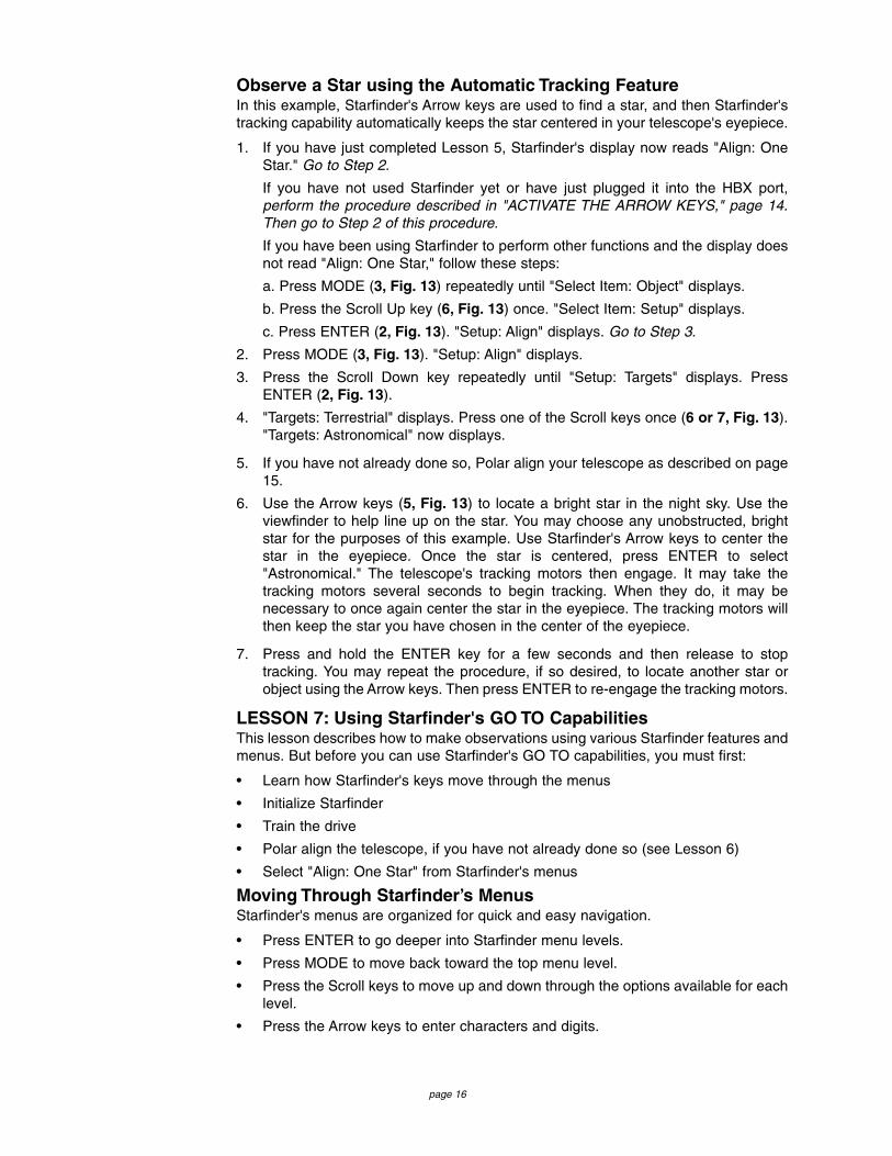
Observe a Star using the Automatic Tracking FeatureIn this example, Starfinder's Arrow keys are used to find a star, and then Starfinder'stracking capability automatically keeps the star centered in your telescope's eyepiece.
1. If you have just completed Lesson 5, Starfinder's display now reads "Align: OneStar." Go to Step 2.
If you have not used Starfinder yet or have just plugged it into the HBX port,perform the procedure described in "ACTIVATE THE ARROW KEYS," page 14.Then go to Step 2 of this procedure.
If you have been using Starfinder to perform other functions and the display doesnot read "Align: One Star," follow these steps:
a. Press MODE (3, Fig. 13) repeatedly until "Select Item: Object" displays.
b. Press the Scroll Up key (6, Fig. 13) once. "Select Item: Setup" displays.
c. Press ENTER (2, Fig. 13). "Setup: Align" displays. Go to Step 3.
2. Press MODE (3, Fig. 13). "Setup: Align" displays.
3. Press the Scroll Down key repeatedly until "Setup: Targets" displays. PressENTER (2, Fig. 13).
4. "Targets: Terrestrial" displays. Press one of the Scroll keys once (6 or 7, Fig. 13)."Targets: Astronomical" now displays.
5. If you have not already done so, Polar align your telescope as described on page15.
6. Use the Arrow keys (5, Fig. 13) to locate a bright star in the night sky. Use theviewfinder to help line up on the star. You may choose any unobstructed, brightstar for the purposes of this example. Use Starfinder's Arrow keys to center thestar in the eyepiece. Once the star is centered, press ENTER to select"Astronomical." The telescope's tracking motors then engage. It may take thetracking motors several seconds to begin tracking. When they do, it may benecessary to once again center the star in the eyepiece. The tracking motors willthen keep the star you have chosen in the center of the eyepiece.
7. Press and hold the ENTER key for a few seconds and then release to stoptracking. You may repeat the procedure, if so desired, to locate another star orobject using the Arrow keys. Then press ENTER to re-engage the tracking motors.
LESSON 7: Using Starfinder's GO TO CapabilitiesThis lesson describes how to make observations using various Starfinder features andmenus. But before you can use Starfinder's GO TO capabilities, you must first:
• Learn how Starfinder's keys move through the menus
• Initialize Starfinder
• Train the drive
• Polar align the telescope, if you have not already done so (see Lesson 6)
• Select "Align: One Star" from Starfinder's menus
Moving Through Starfinder’s MenusStarfinder's menus are organized for quick and easy navigation.
• Press ENTER to go deeper into Starfinder menu levels.
• Press MODE to move back toward the top menu level.
• Press the Scroll keys to move up and down through the options available for eachlevel.
• Press the Arrow keys to enter characters and digits.
page 17
Initializing StarfinderThis exercise describes how to initialize Starfinder.
Initialization is a procedure that enables Starfinder to operate correctly. When you firstuse Starfinder, it doesn't yet "know" the location of the observing site or the time ordate of the observation session. During the Initialization procedure, you will enter thisinformation. Starfinder then uses the information to calculate the location of celestialobjects (such as stars and planets) and to move your telescope correctly for variousoperations.
NOTE: Normally, you will enter the Time and Date at the beginning of eachobserving session, but you will only perform the full Initialization procedure(i.e., entering the Location information as well as the Time and Date) thefirst time you use Starfinder or after performing a Reset. Fig. 16 depicts anexample of Starfinder Initialization procedure.
NOTE: See "STARFINDER CONTROLS," page 23, for a detaileddescription of Starfinder's Keys.
1. Make sure that the telescope is assembled correctly, and that the batteries and themotor drives are installed as described previously.
2. Plug Starfinder's cord into the HBX port, as previously described, or if Starfinderis already plugged in, unplug it briefly and then plug it back in again.
3. A copyright message lights on Starfinder’s LCD display and a message warningnot to look at the Sun scrolls across the display. Press the key prompted byStarfinder to acknowledge the message has been read and understood.
4. The Getting Started menu displays a scrolling message with two choices:
a. Press and hold down the Speed/? key (8, Fig. 13) for about 2 seconds for information on Starfinder functions and controls. When finished, press MODE(3, Fig. 13) to exit Help, or,
b. Press ENTER (2, Fig. 13) to bypass the Help tutorial and continue withInitialization.
5. Starfinder then prompts you to enter the current date: a. To enter numbers, press either the Up or Down Arrow key (5, Fig. 13) to scroll
through numbers 0 through 9. After the desired number is displayed, use theRight Arrow key (5, Fig. 13) to move the cursor from one number to the nextin the day display (or use to Left Arrow key to move in the other directionacross the display, if necessary).
b. Use the Right Arrow key (5, Fig. 13) to move the cursor to the month. Use theScroll keys (8, 9, Fig. 13) to cycle through the list of months. When the currentmonth is displayed, use the Right Arrow (5, Fig. 13 to move the cursor to theyear.
c. Use the Up and Down Arrow keys to enter all four digits of the current year.Use the Right Arrow key to move the cursor from one number to the next.
d. Press ENTER (2, Fig. 13) when the entire date has been entered.
6. Starfinder then prompts you to enter the current time. Use the Up and Down Arrowkeys to enter digits and the Right and Left Arrow keys move the cursor across thescreen as described in the previous step. Enter the current time (use a "0" for thefirst digit if less than 10). Use the Up Arrow key (7, Fig. 13) to scroll through "AM,""PM,'" or "blank." The "blank" option selects the 24-hour (i.e., military time) clock.Then press ENTER to start the clock.
NOTE: When multiple choices are available within a menu option, theoption that is currently selected is usually displayed first and highlighted bya right pointing arrow (>).

page 18
7. Starfinder then prompts you to enter the status of Daylight Savings Time. Pressone of the Scroll keys to toggle between the YES/NO settings. Select the desiredsetting by pressing ENTER.
NOTE: Daylight Savings Time may be referred to by a different name invarious areas of the world.
8. If you have previously entered the Country/State and City of your observing site(as described in "ACTIVATE THE ARROW KEYS," page 14), go to step 9. If youhave not entered this information, perform the following steps:
a. Starfinder prompts you to enter the Country or State (listed alphabetically) ofthe observing site. Use the Scroll keys to cycle through the database ofcountries, states, and provinces. Press ENTER when the correct locationdisplays.
b. Starfinder then prompts you to enter the nearest city (listed alphabetically) tothe observing site. Use the Scroll keys to cycle through the database of cities.Press ENTER when the correct city appears on screen.
NOTE: Starfinder only prompts you to enter Country/State and City the firsttime it is activated. These prompts do not appear again, unless you resetStarfinder (see "RESET," page 32). However, if you change yourgeographic location, you can change the location information by using theSite option of the Setup menu. See "SITE," page 32, for detailedinformation.
9. System Initialization is complete and the display reads "Align: One Star." Afterperforming the Initialization procedure, you MUST train your drive. Continue topage 19.
ENTER
Enter Time:08:00:00PM (default)
1 (1X)
(1X)
1 (3X)
(1X)
4 (4X)
7 (7X)
PM
Enter Time:11:47:00PM
ENTER
Daylight Savings>NO
(00) Meade (1.0)S T A R F I N D E R
Initializing. . .
WARNING LOOKING AT . . .
ENTER
Getting StartedFor a Detailed...
Enter Date:01-Jan-2000
2 (2X)
(1X)
6 (5X)
(1X)
Mar (2X)
2000 (4X)
2001 (1X)
Enter Date:26-Mar-2001
ENTER
Country/State AFGHANISTAN
Country/State CALIFORNIA
Nearest City ALAMEDA NAS
Nearest City IRVINE
Setup Align
MultiplePresses
ENTER
ENTER
MultiplePresses
(default)
Press the appropriate key
Fig. 16: Example of the Initialization procedure.
Note:
The following parametersare used in the exampledepicted in Fig. 16:
Date: March 26, 2001
Time: 11:47 PM
Location: Irvine,California
In this example, it isassumed that theCountry/State and Citydata has not yet beenentered into Starfinder.

page 19
Training the DriveNext, train the drive using Starfinder. Perform this procedure the first time you useStarfinder with your telescope, after a Reset, or if you are experiencing any pointingaccuracy problems. Training the drive gives your telescope a higher degree of point-ing accuracy.
NOTE: Use a terrestrial object, such as a telephone pole or lamp post, totrain the drive. It is best to perform this procedure during the daytime.Complete this exercise once every 3 to 6 months to maintain the highestlevel of telescope pointing accuracy.
1. If you have just performed "INITIALIZING STARFINDER," go to step 2.
If you have not yet initialized Starfinder, go to page 17 and follow the proceduredescribed in "INITIALIZING STARFINDER." Then go to to step 2 of this procedure.
2. Keep pressing MODE until "Select Item: Object" displays. 3. Press the Scroll Up key once. "Select: Item: Setup" displays.4. Press ENTER to access the Setup menu. "Setup: Align" displays.5. Keep pressing the Scroll Up key until "Setup: Telescope" displays.6. Press ENTER to access the Telescope menu. "Telescope: Focal Length" displays.7. Keep pressing the Scroll Down key until "Telescope: Train Drive" displays.8. Press ENTER to choose the Train Drive option. "Train Drive: RA Train" displays.9. Press ENTER to begin RA (Right Ascension or horizontal) training.
10. "Drive Setup: For this...." begins to scroll across the display. This is a reminder topoint your telescope at a terrestrial object. Press ENTER when the telescope ispointing at the desired terrestrial object.
11. "Center reference object" displays. Center your target object using the Arrow keys.When centered, press ENTER.
12. The telescope slews and "Press > until it is centered" displays. Press the RightArrow key until the target is centered again. Then press ENTER.
NOTE: If you pass the object when pressing the Arrow key, you cannot slewthe telescope back in the other direction. Press MODE until "Train Drive: RATrain" displays and begin the procedure over again.
13. The telescope slews and "Press < until it is centered" displays. Press the LeftArrow key until the target is centered again. Then press ENTER.
14. "Train Drive: RA Train" displays again. Press the Scroll Down key and "Train Drive:Dec Train" displays. Press ENTER to begin Dec (Declination or vertical) training.
15. "Drive Setup: For this...." begins to scroll across the display. This is anotherreminder to point your telescope at a terrestrial object. Press ENTER when thetelescope is pointing at the desired terrestrial object.
16. "Center reference object" displays. Center your target object using the Arrow keys.When centered, press ENTER.
17. The telescope slews and "Press until it is centered" displays. Press the Up Arrowkey until the target is centered again. Then press ENTER.
18. The telescope slews and "Press until it is centered" displays. Press the DownArrow key until the target is centered again. Then press ENTER. "Train Drive: DecTrain" displays again. You have now completed this procedure. Continue onto thenext procedure, "Align Your Telescope Using Starfinder."
>
>

page 20
Align Your Telescope Using StarfinderAfter completing the "Train the Drive" procedure, align your telescope using Starfinder.The fastest and easiest way to start observing with Starfinder's Go To capabilities is toalign your telescope using One-Star (Polar) Alignment. An alternate method, Two-Staralignment, is described later in this manual.
1. With "Train Drive: Dec Train" displayed (or scroll to this menu, if necessary), keeppressing MODE until "Select Item: Setup" is displayed. Press ENTER.
2. "Setup: Align" displays. Press ENTER. "Align: One Star" displays. Press ENTER.
3. "German North" displays and a scrolling message prompts you to Polar align yourtelescope. See "TO POLAR ALIGN THE TELESCOPE," page 15, for a descriptionof how to Polar align your telescope. Press ENTER after you finish the alignmentprocedure.
4. "Ctr. Polaris" displays and the telescope begins to slew. Starfinder beeps and"Adjust Mount" displays after the telescope finishes slewing.
5. A scrolling message prompts you to unlock both the Latitude Lock (23, Fig. 2b)and the Azimuth Lock (24, Fig. 2b).
6. Manually rotate (do NOT use Starfinder's Arrow keys!) the telescope until Polarisis centered once again in the eyepiece. Then re-lock both the Latitude andAzimuth Locks and press ENTER.
7. Starfinder then chooses another star from its database and the telescope slews tothe star for alignment. It may not appear in the field of view in the eyepiece. Thealignment star should be easily recognized and be the brightest star in the area ofthe sky where the telescope is pointing. Use the Arrow keys to move the telescopeuntil the star is visible and centered in the eyepiece. When the star is centered,press ENTER.
Another method to find the alignment star if it does not appear in the eyepiece isto perform a "spiral search." If the alignment star is not visible in the eyepiecewhen the telescope finishes its search, press GO TO and the telescope startsslewing in a spiral pattern at a very slow speed around the search area. Lookthrough the eyepiece and when the object does become visible, press MODE tostop the spiral search. Then use the Arrow keys to center the object and pressENTER to complete the alignment procedure.
NOTE: Starfinder locates alignment stars based on the date, time, andlocation entered. The alignment stars may change from night to night. Allthat is required is for the observer to center the selected star in the eyepiecewhen prompted.
Check MountIt is possible for the 4504 telescope to move in such a way that the telescope tubemight interfere with the mount while slewing. Starfinder has a feature called "CheckMount" to alert you of this possibility.
If "Check Mount" displays, inspect the assembly to see if it's moving in such a way thatthe mount, tube, levers, motors, etc., might catch on or collide with each other. Alsoinspect the cable to see if it might become tangled. If any of these possibilities seemlikely to occur, press MODE to abort the current operation of the telescope. If they donot seem likely, press GO TO to continue with the current operation. Press any keyduring slewing to stop the telescope.
If "Check Mount" displays during alignment, and interference seems likely, press MODE.Select another alignment star by pressing one of the Scroll keys to select the next align-ment star in the database. Repeat this procedure as necessary to align the telescope.To abort the alignment procedure, press and hold MODE for about two seconds.

page 21
Which One’s the Alignment Star?If Starfinder has chosen an alignment star that you are unfamiliar with, how can yoube sure if the star in your eyepiece is really the alignment star?
The rule of thumb is that an alignment star is usually the brightest star in that area ofthe sky. When you view an alignment star in an eyepiece, it will standout dramaticallyfrom the rest of the stars in that portion of the sky.
If you have an obstruction, such as a tree or a building blocking your view of the align-ment star, or if you have any doubts at all about the star that has been chosen, noproblem. Just press the Scroll Down key and Starfinder will find another star to alignupon.
Go To SaturnAfter performing the Train the Drive and the One-Star alignment procedures, the motordrive begins operating and the telescope is aligned for a night of viewing. Objects inthe eyepiece should maintain their position even though the Earth is rotating beneaththe stars.
IMPORTANT NOTE: Once aligned, only use the Starfinder menus or Arrowkeys to move the telescope. Do not loosen the telescope locks, or move thebase manually, or alignment will be lost.
This exercise demonstrates how to select an object for viewing from Starfinder’s data-base, i.e., Saturn. Note that Saturn is not visible all year long and it may be necessaryfor you to choose another object from Starfinder's database. However, the procedureis identical to the one used for observing Saturn.
1. After the telescope is aligned, “Select Item: Object” displays. Press ENTER. If“Select Item: Object” is not currently displayed, press MODE repeatedly until itdisplays, then press ENTER.
2. “Object: Solar System” displays. Press ENTER.
3. “Solar System: Mercury” displays. Use the Scroll Down key until “Solar System:Saturn” displays.
4. Press ENTER. “Calculating” displays. Then “Saturn” and a set of coordinatesdisplays. Saturn’s (and other planets’) coordinates change throughout the year.
5. Press GO TO. “Saturn: Slewing...” displays and the telescope slews until it findsSaturn. You may need to use the Arrow keys to center Saturn precisely in theeyepiece. Starfinder then automatically slews (moves) the telescope so that ittracks Saturn (or whatever other object you may have chosen). Saturn remainscentered in the eyepiece.
Using the Guided TourThis example demonstrates using “Tonight’s Best” Guided Tour.
1. After observing Saturn, press MODE twice so that “Select Item: Object” displaysagain. If “Select Item: Object” is not currently displayed, press MODE repeatedlyuntil it displays.
2. Press the Scroll Down key twice. “Select Item: Guided Tour” displays.
3. Press ENTER. “Guided Tour: Tonight’s Best” displays. Press ENTER to select thistour.
NOTE: If you wish to try out other Guided Tours, press the Scroll Down keyto scroll through other tour choices. When the tour you wish to selectdisplays, press ENTER.

page 22
You have now completed all the Lessons for the basic operation of your 4504telescope. All of Starfinder's features perform in the same way as the featurescovered in Part 1. Practice these procedures so you can apply them to themore advanced Starfinder menu features presented in Part 2 of this manual.
4. “Tonight’s Best: Searching...” displays. After calculating, “Tonight’s Best: Jupiter”displays.
NOTE: Different objects may be displayed on a tour list on any given night.
Press ENTER and then use the Scroll keys to display information about the object.Press Mode to exit the information display. Press GO TO to move the telescopeto the object.
5. Press MODE to return to the Tour list. Press the Scroll keys to scroll through thelist. Press ENTER when you find the next object you wish to observe.
6. Press MODE and hold for about two seconds to leave the Guided Tour menu.
Some Observation Tips• Avoid touching the eyepiece while observing through the telescope. Vibrations
resulting from such contact will cause the image to move. Likewise, avoidobserving sites where ground-based vibrations may resonate the tripod. Viewingfrom the upper floors of a building may also introduce image movement.
• Allow your eyes a few minutes to become adapted to the dark before attemptingany serious astronomical observations. Use a red filtered flashlight to protect yournight vision when reading star maps or inspecting the components of thetelescope.
• Avoid setting up the telescope inside a room and observing through an openwindow (or worse yet, a closed window). Images viewed in such a manner mayappear blurred or distorted due to temperature differences between inside andoutside air. Also, it is a good idea to allow your telescope a chance to reach theambient (surrounding) outside temperature before starting an observing session.
• Avoid viewing objects low on the horizon. Objects will appear better resolved withfar greater contrast when viewed higher in the sky. If images appear to “shimmer”in the eyepiece, reduce eyepiece power until the image steadies. This condition iscaused by air turbulence in the upper atmosphere.
page 23
PART TWO: Starfinder Controls and MenusThis section describes how Starfinder operates, including:
• Starfinder's controls
• How to move through Starfinder's menus
• Alignment setups
• Starfinder's Menus
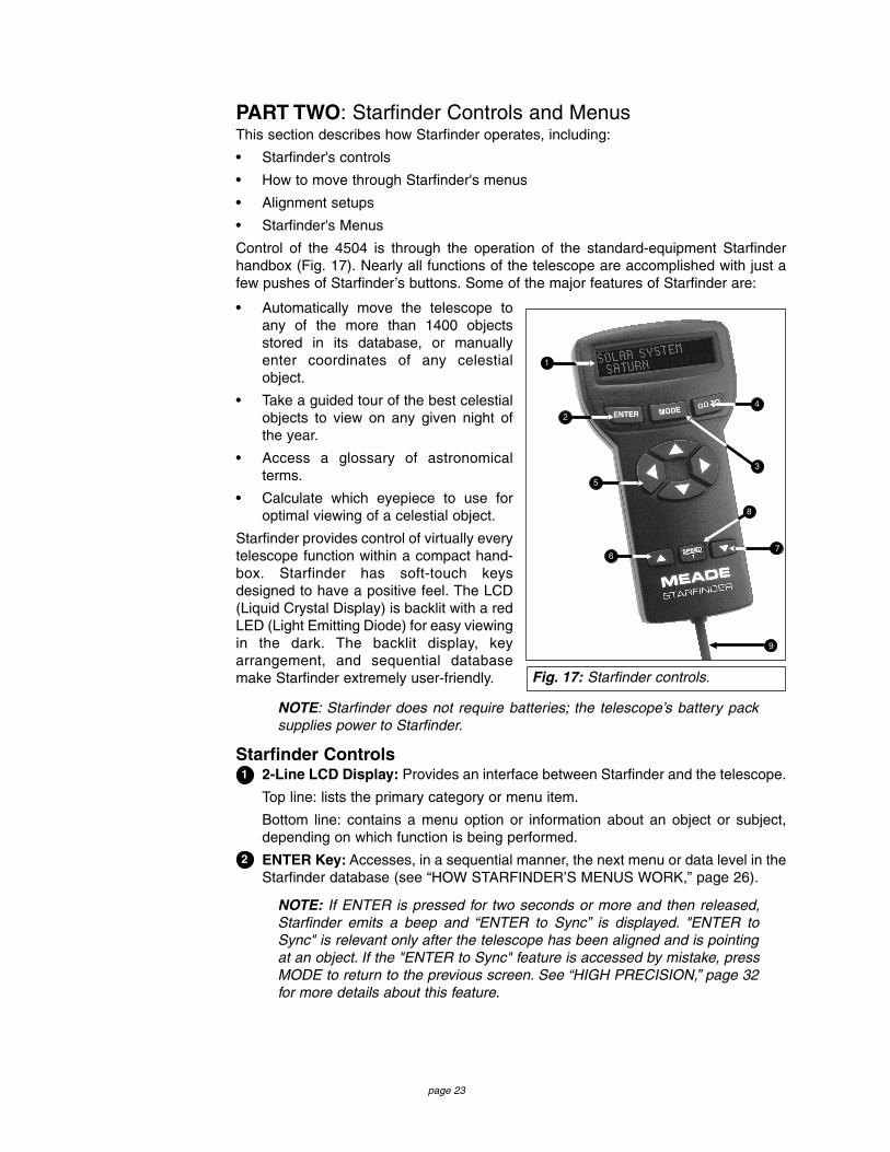
Control of the 4504 is through the operation of the standard-equipment Starfinderhandbox (Fig. 17). Nearly all functions of the telescope are accomplished with just afew pushes of Starfinder’s buttons. Some of the major features of Starfinder are:
• Automatically move the telescope toany of the more than 1400 objectsstored in its database, or manuallyenter coordinates of any celestialobject.
• Take a guided tour of the best celestialobjects to view on any given night ofthe year.
• Access a glossary of astronomicalterms.
• Calculate which eyepiece to use foroptimal viewing of a celestial object.
Starfinder provides control of virtually everytelescope function within a compact hand-box. Starfinder has soft-touch keysdesigned to have a positive feel. The LCD(Liquid Crystal Display) is backlit with a redLED (Light Emitting Diode) for easy viewingin the dark. The backlit display, keyarrangement, and sequential databasemake Starfinder extremely user-friendly.
NOTE: Starfinder does not require batteries; the telescope’s battery packsupplies power to Starfinder.
Starfinder Controls2-Line LCD Display: Provides an interface between Starfinder and the telescope.
Top line: lists the primary category or menu item.
Bottom line: contains a menu option or information about an object or subject,depending on which function is being performed.
ENTER Key: Accesses, in a sequential manner, the next menu or data level in theStarfinder database (see “HOW STARFINDER’S MENUS WORK,” page 26).
NOTE: If ENTER is pressed for two seconds or more and then released,Starfinder emits a beep and “ENTER to Sync” is displayed. "ENTER toSync" is relevant only after the telescope has been aligned and is pointingat an object. If the "ENTER to Sync" feature is accessed by mistake, pressMODE to return to the previous screen. See “HIGH PRECISION,” page 32for more details about this feature.
Fig. 17: Starfinder controls.
1
2
5
4
3
6
8
7
9
1
2

page 24
MODE Key: Returns to the previous menu or data level in the Starfinder databaseuntil the top level, “Select Item," is reached. The MODE key is similar to theESCAPE key on a computer.
NOTE: Pressing MODE while in the Select Item level moves Starfinder tothe topmost screen: "Select Item: Object."
NOTE: If MODE is pressed and held for two seconds or more, the followinginformation is then available using the Scroll keys (6 and 7, Fig. 17):
• Right Ascension and Declination coordinates
• Altitude and Azimuth coordinates
• Local Time and Local Sidereal Time (LST)
• Timer and Alarm Status
Press MODE again to return to the previous menu.
GO TO Key: Slews the telescope to the coordinates of the currently selectedobject. While the telescope is slewing, the operation may be aborted at any timeby pressing any key except GO TO. Pressing GO TO again resumes the slew tothe object.
The GO TO key also allows you to perform a "spiral search." A spiral search isuseful when the telescope slews to an object, but that object is not visible in theeyepiece after the telescope finishes it search. (This sometimes occurs during analignment procedure. See "ALIGN YOUR TELESCOPE USING STARFINDER,"page 20.) Press GO TO when the slew is finished and the telescope starts slewingin a spiral pattern at a very slow speed around the search area. Look through theeyepiece and when the object does become visible, press MODE to stop the spiralsearch. Then use the Arrow keys to center the object.
Arrow Keys: Slew the telescope in a specific direction (up, down, left, and right),at any one of seven different speeds (speed selection is explained in “SLEWSPEEDS,” page 14). The following functions are also available with the Arrowkeys:
• Data Entry: Use the Up and Down Arrow keys to Scroll through the letters ofthe alphabet and numerical digits. The Down Arrow key starts with the letter "A"and the Up Arrow key starts with the digit "9." Use the Left and Right Arrow keysto move the blinking cursor left and right across the LCD display.
• Polar Alignment: Use the Left and Right Arrow keys to move the telescope.The Left Arrow key rotates the telescope counterclockwise on the RightAscension axis, while the Right Arrow key rotates it clockwise.
Scroll Keys: Access database options within a selected menu. The menu isdisplayed on the first line of the screen. Options within the menu are displayed,one at a time, on the second line. Press the Scroll keys to move through theoptions. Press and hold a Scroll key to move quickly through the options.
The Scroll keys also scroll through the letters of the alphabet and numerical digits.
NOTE: The Scroll Down key and the Down Arrow key move forward throughthe alphabet & digits (A to Z, 0-9) and the Scroll Up key and the Up Arrowkey move backward (Z to A, 9-0).
Press and hold the Up Arrow key to speed up the rate at which a message scrollsacross the display. Press and hold the Down Arrow key to slow down the scrollingspeed. When the display is scrolling at a speed that is comfortable for reading,release the Scroll key.
3
4
5
76

page 25
Speed/? Key: Briefly pressing the Speed/? key cycles through the seven slewspeeds that move the telescope (see “Slew Speeds,” page 14).
NOTE: Pressing the Speed/? key briefly changes the slew speed. Holdingdown the Speed/? key longer (one to two seconds) accesses the Helpfunction.
The Speed/? key also accesses the "Help" file. "Help" provides on-screeninformation on how to accomplish whatever task is currently active.
Hold down the Speed/? key and then follow the prompts on the display to accessdetails of Starfinder functions in the Help feature. The Help system is essentiallyan on-screen instruction manual.
If you have a question about a Starfinder operation (i.e., INITIALIZATION,ALIGNMENT, etc.), hold down the Speed/? key and follow the directions that scrollon the second line of the LCD screen. When a word appears in [brackets], pressENTER to access the word in the Starfinder Glossary. A definition or more detailedinformation is displayed. Press MODE to return to the scrolling Starfinder Helpdisplay.
When satisfied with the Help provided, press MODE to return to the originalscreen and continue with the chosen procedure.
Coil Cord: To operate, the Starfinder coil cord must be plugged into the HBX port(9, Fig. 11) of the Dec motor box.
8
9

page 26
How Starfinder's Menus WorkIt is important to understand that Starfinder's menu selections are set in a loop. Thismeans that pressing the Scroll Down key cycles down through all the available optionswithin a given category and then returns to the first option. The Scroll Up key cyclesup through the options in the opposite order. Note that this capability is a quick way toget to an option that is near the bottom of the list. The following example demonstratesthis capability.
To navigate to the "Select Item: Setup" menu option when the "Select Item:Object" menu is displayed:
1. Press the Scroll Down key four times or the Scroll Up key once.
The screen in Fig. 19 displays two lines of information.The top line shows the current menu level. The secondline displays an option which may be selected withinthat menu level. Some options are choices that selectthe next menu level down. The Scroll keys move up anddown within the list of available options, showing oneoption at a time.
When the desired option is displayed on the second line, press the ENTER key tochoose that option and move down one menu level.
To leave a level (e.g., the wrong menu option is chosen), press the MODE key.
IMPORTANT NOTE: No matter how many menu levels of Starfinder aretraveled, each press of the MODE key moves up a level, until the top menulevel, "Select Item," is reached. Once in the Select Item level, press MODEto return to the topmost available screen: "Select Item: Object."
Starfinder Navigation ExerciseTo demonstrate how the Starfinder menu structure works, the following exercise cal-culates the Sunset time so an evening observing session can be planned.
Select Item Solar System
Select Item Object
ENTER
Fig. 19: Starfinder levels.
The Universe ofStarfinder
Select Item: Setup
Select Item: Utilities
Select Item: Glossary
Select Item: Guided Tour
Select Item: Event
Select Item: Object
SETUPQuick, easy alignmentpermits all telescopeoperations with onlya 2-minute setup.
UTILITIESCalculate eyepiecemagnifications; set thetimer for an observingsession; or survey userlandmarks in 30-secondintervals.
GLOSSARYDiscover the world of astronomyby alphabetically accessing astronomical terms.
OBJECT Select from over 1400 database objects andpress GO TO to move the telescope automatically to theobject and place it in the telescopic field of view.
EVENT Access the time ofan astronomicalevent, such as the rising or settingtimes of the Moon.
GUIDED TOURJourney through theuniverse as Starfinderescorts you to the best celestial objectsat your location.
Fig. 18: The Starfinder universe.

page 27
NOTE: To perform an accurate calculation, Starfinder must be properlyinitialized with the current date, time, and location of the observing site.
To enter the current date, time, and location information of your observingsite, see “ INITIALIZE STARFINDER” page 17, before proceeding with thisexercise.
To Calculate Sunset time:1. Press the MODE key several times, until "Select Item: Object" displays.
2. Press the Scroll Down key once to display the Event option in the Select Itemmenu.
3. Press the ENTER key to choose the Event option and move down a menu level."Event: Sunrise" displays.
4. Press the Scroll Down key once to display the Sunset option in the Event menu.
5. Press the ENTER key to choose the Sunset option and move down another menulevel.
6. Starfinder calculates the Sunset time based on the current date, time, andlocation. Starfinder then displays the time of Sunset.
7. Press MODE once to start moving back up through the Starfinder menu levels.The first menu level up is Event.
8. Press MODE again to move up another menu level. This is the top menu level,Select Item.
9. Press MODE again to return to the starting point of "Select Item: Object."
Solar SystemMercuryEtc.MoonAsteroidsComets
ConstellationsAndromedaEtc.
Deep SkyNamed ObjectGalaxiesNebulaePlanetary Neb.Etc.
StarNamed SAO CatalogDoubleEtc.
SatelliteSelectAddDeleteEdit
User ObjectsSelectAddDeleteEdit
LandmarksSelectAddDelete
Identify
SunriseSunsetMoonriseMoonsetMoon Phases
Next Full MoonNext New MoonNext 1st QtrNext 3rd Qtr
Meteor ShowersQuadrantidsLyridsEta AquaridsDelta AquaridsPerseidsOrionidsTauridsLeonidsGeminidsUrsids
Solar EclipsesLunar EclipsesMin. of AlgolAutumn EquinoxVernal EquinoxWinter SolsticeSummer Solstice
Tour Objects A...Accretion DiskEtc.
B...C...D...E...F...G...H...I...J...K...L...M...N...O...P...Q...R...S...T...U...V...W...X...Y...Z...
TimerSetStart & Stop
AlarmSetOn & Off
Eyepiece Calc.Field of ViewMagnificationSuggest
Display OptionsSun WarningGetting Started
Brightness Adj.Contrast Adj.Battery AlarmLandmark SurveySleep ScopePark Scope
Align
One StarTwo Star
DateTimeDaylight SavingTelescope
Focal LengthAz/Alt RatioTrain DriveTracking RateReverse L/RReverse Up/DnCalibrate MotorHigh Precision
TargetsAstronomicalTerrestrial
SiteSelectAddDelete Edit
Owner InfoDownloadStatisticsReset
Select Item: Object
Select Item: Event
Select Item: Guided Tour
Select Item: Glossary
Select Item: Utilities
Select Item: Setup
Tonight's BestHow Far is FarA Star's Life
Fig. 20: The complete Starfinder menu structure.

page 28
Starfinder MenusObject MenuAlmost all observing with Starfinder is performed using the Object menu. (Note:Exceptions include Guided Tour and Landmark Survey.) See “GO TO SATURN,” page20, for an example of observing using the Object menu. Also see “USING THEGUIDED TOUR,” page 21.
Many Starfinder menu categories contain databases. A Starfinder database is a list ofviewable objects. When one of these objects is selected, Starfinder moves your tele-scope (if properly aligned) and points it at the selected object.
Object Menu Options:Solar System is a database of the eight planets (Earth is not included) in order outfrom the Sun, followed by the Moon, asteroids, and comets.
Constellation is a database of all 88 Northern and Southern Hemisphere constella-tions. When this menu option is chosen and a constellation name appears on the firstline of the screen, press GO TO once to change the second line to the name of thebrightest star in the constellation. Press GO TO a second time to slew the telescopeto that star. Use the Scroll keys to cycle through the list of stars in the constellation,from brightest to dimmest.
Deep Sky is a database of objects outside our Solar System such as nebulae, starclusters, galaxies, and quasars.
Star is a database of stars listed in different categories such as named, double, vari-able, or nearby.
User Objects allows the user to define deep-sky objects of specific interest that arenot currently in the Starfinder database. See "APPENDIX C," page 42, for detailedinformation.
Landmarks stores the location of terrestrial points of interest in the permanentStarfinder database.
IMPORTANT NOTE: To use the Landmark function, the telescope must belocated and aligned exactly as when the landmark was added to thedatabase.
• Select: To select a landmark already in the database, choose the Select optionand scroll through the list. Press ENTER to select a landmark, then press GO TOand the telescope slews to the object.
• Add: To add a landmark, choose the Add option. Enter the name of the landmark.Locate the object with the Arrow keys (the telescope must be aligned) and centerthe landmark. Press ENTER.
Use the Landmark Survey option in the Utilities menu to sequentially view all land-marks entered into Starfinder. See "LANDMARK SURVEY," page 32.
Identify is an exciting feature for an observer who wants to scan the night sky andstart exploring.
After the telescope has been properly aligned, use the Starfinder Arrow keys to moveabout in the sky, and then follow this procedure:
IMPORTANT NOTE: Only use the Arrow keys to move the telescope duringthe Identify procedure. Do not loosen the telescope locks, or move the base,or alignment will be lost.

page 29
1. When a desired object is visible in the eyepiece, press MODE until the "SelectItem: Object" menu is displayed.
2. Scroll through the Object menu options until "Object: Identify" displays.
3. Press ENTER to search the database for the identity of the object being observed.
4. If the telescope is not directly on a Starfinder database object, the nearestdatabase object is located and displayed on the screen. Press GO TO and thetelescope slews to that object.
Event MenuThe Event menu provides access to dates and times of astronomical events. TheEvent database includes:
Sunrise and Sunset calculates the time that the Sun rises or sets on the current date.Find rise and set times for other dates (e.g., a date three months in the past or future)by entering the new date into the "Setup: Date" menu.
Moonrise and Moonset calculates the time that the Moon rises or sets on the currentdate. Find rise and set times for other dates by entering a new date into the "Setup:Date" menu.
Moon Phases displays the date and time of the next Full, New, 1st Quarter, and 3rdQuarter Moon.
Meteor Showers provides information on upcoming meteor showers (e.g., thePerseids, the Leonids, etc.), the dates of the showers, and when they reach maximum.
NOTE: Meteors are fast moving objects that cover large areas of the skyand are usually best observed with the naked eye.
Solar Eclipse lists upcoming Solar Eclipses, including the date and type (total, annu-lar, or partial) of eclipse, and the location and time of the first and last contacts of theMoon's shadow. Use the Scroll Up and Down keys to display the available data.
Lunar Eclipse lists upcoming Lunar Eclipses, including the date and type (total, partial,penumbral) of eclipse. Use the Scroll Up and Down keys to display the available data.
Min. (Minimum) of Algol is the minimum brightness of the dramatic eclipsing binarystar system, Algol. It is relatively close at a distance of 100 light years. Every 2.8 daysduring a 10-hour period, Algol undergoes a major change in apparent magnitude asone of the two stars passes behind the other. The combined magnitude of the twostars thus dips from +2.1 to a minimum of +3.4 halfway through the eclipse as the sec-ond star is hidden. Starfinder calculates minimum magnitude time at mid-eclipse.
Autumn and Vernal Equinox calculates the time and date of the fall or spring equinoxof the current year.
Winter and Summer Solstice calculates the time and date of the winter or summersolstice of the current year.
Glossary MenuThe Glossary menu provides an alphabetical listing of definitions and descriptions forcommon astronomical terms and Starfinder functions. Access directly through theGlossary menu or through hypertext words embedded in Starfinder.
A hypertext word is any word in [brackets], usually found when in the Starfinder Helpfunction or in a scrolling message such as a description of a planet or star. PressENTER whenever a hypertext word is displayed and Starfinder links directly to theglossary entry for that word.
NEVER point thetelescope directlyat or near theSun at any time!Observing theSun or an eclipseof the Sun, evenfor the smallestfraction of a sec-ond, will result ininstant and irre-versible eye dam-age, as well asphysical damageto the telescopeitself.

page 30
To access a hypertext word directly from the Glossary menu, use the Scroll keys toscroll through the alphabet. Press ENTER on the desired letter. Scroll to the desiredentry, then press ENTER to read the description.
Utilities MenuThe Utilities menu provides access to several extra features within Starfinder, includ-ing a countdown timer and an alarm. The Utilities functions include:
Timer selects a countdown timer. This feature is useful for functions such as astropho-tography. To use the Timer, press ENTER, then choose "Set" or "Start/Stop."
• Set: Enter the time to be counted down (in hours, minutes, and seconds), thenpress ENTER.
• Start/Stop: Activates the timer set previously. Use the Scroll keys to togglebetween ON and OFF. When ON is displayed, press ENTER to activate the timer.When the timer runs out, four beeps sound and the timer is deactivated.
Alarm selects a time for an alarm signal as a reminder. To use the Alarm, pressENTER, then choose "Set" or "Start/Stop."
• Set: Enter the time of day for the alarm to sound (in hours, minutes, and seconds),then press ENTER.
• Start/Stop: Activates the alarm set previously. Use the Scroll keys to togglebetween ON and OFF. When ON is displayed, press ENTER to activate the alarm.When the alarm time arrives, Starfinder beeps. Press ENTER to deactivate thealarm.
Eyepiece Calc calculates information about an eyepiece for the specific telescope towhich Starfinder is connected:
• Field of View: Scroll through a list of available eyepieces. When an eyepiece isselected, the field of view is calculated.
• Magnification: Scroll through a list of available eyepieces. When an eyepiece isselected, the magnification is calculated.
• Suggest: Starfinder calculates and suggests the best eyepiece for viewing, basedon the telescope and the object being viewed.
Display Options enables or disables Starfinder’s two initial displays. If both displaysare disabled, Starfinder begins with the Date display.
• Sun Warning: Turns the Sun warning message on or off.
• Getting Started: Turns the “Getting Started” message on or off.
Brightness Adj: Adjusts the brightness of the display using the Scroll keys. Whencomplete, press ENTER.
Contrast Adj: Adjusts the contrast of the display using the Scroll keys. When com-plete, press ENTER.
NOTE: This feature is usually only required in very cold weather.
Landmark Survey automatically slews the telescope to all user-defined landmarkswith a short pause at each location. Press ENTER to start the survey. While a slew isin progress, press any key to skip that object and go to the next landmark on the list.To observe a landmark for a longer period, press MODE when paused on the objectto stop the survey. Press ENTER to restart the survey at the first object on the list.
Sleep Scope is a power saving option that shuts down Starfinder and the telescopewithout forgetting its alignment. Press ENTER to activate the Sleep function.Starfinder goes dark, but the internal clock keeps running. Press any key, exceptENTER, to re-activate Starfinder and the telescope.

page 31
Park Scope is designed for a telescope that is not moved between observing ses-sions. Align the telescope one time, then use this function to park the telescope. Nexttime it is powered up, enter the correct date and time – and no alignment is required.Pressing ENTER causes the telescope to move to its pre-determined Park position.Once parked, the screen prompts you to turn off the power (i.e., unplugging the bat-tery pack).
IMPORTANT NOTE: When the Park Scope option is chosen and thedisplay prompts to turn off the telescope power, Starfinder is unable to bereturned to operation without unplugging the battery pack and thenplugging it back in.
Setup MenuThe Setup menu’s primary function is to align the telescope (see "ALIGN YOUR TELE-SCOPE USING STARFINDER," page 20). However, there are numerous other fea-tures available within Setup. These options include:
Date changes the date used by Starfinder. This function is useful to check events inthe past or future. Example: set the Date for a day three months in the future and thencheck the" Select Item: Event" menu for the Sunset time or Moon phase on that date.See “EVENT MENU,” page 29.
Time changes the time entered into Starfinder. Setting the correct time is critical forStarfinder to properly calculate locations and events.
Daylight Saving is used to set the status of Daylight Savings time.
NOTE: Daylight Savings Time may be referred to by a different name invarious areas of the world. Check local time to verify.
Telescope accesses the following options:
• Focal Length: Displays the focal length of the selected telescope.
• Az Ratio and Alt Ratio: The Az (Azimuth or horizontal) ratio and Alt (Altitude orvertical) ratio refers to the gears installed in the telescope motors. Do not alterthese numbers.
• Train Drive: Trains the motors to locate objects with more precision.
NOTE: If you are experiencing any problems with pointing accuracy, followthe procedure described in “TRAINING THE DRIVE,” page 19, to insureaccurate pointing and tracking.
Tracking Rate: Changes the speed at which the telescope tracks targets in the sky.
a. Sidereal: The default setting for Starfinder; sidereal rate is the standard rateat which stars move from East to West across the sky due to the rotation of the Earth.
b. Lunar: Choose this option to properly track the Moon over long observing sessions.
c. Custom: Allows entry of user-defined tracking rates.
• Reverse L/R: Reverses the functions of the Left and Right Arrow keys (i.e., theRight key moves the telescope to the left).
• Reverse UP/DOWN: Reverses the functions of the Up and Down Arrow keys (i.e.,the Up key moves the telescope down).
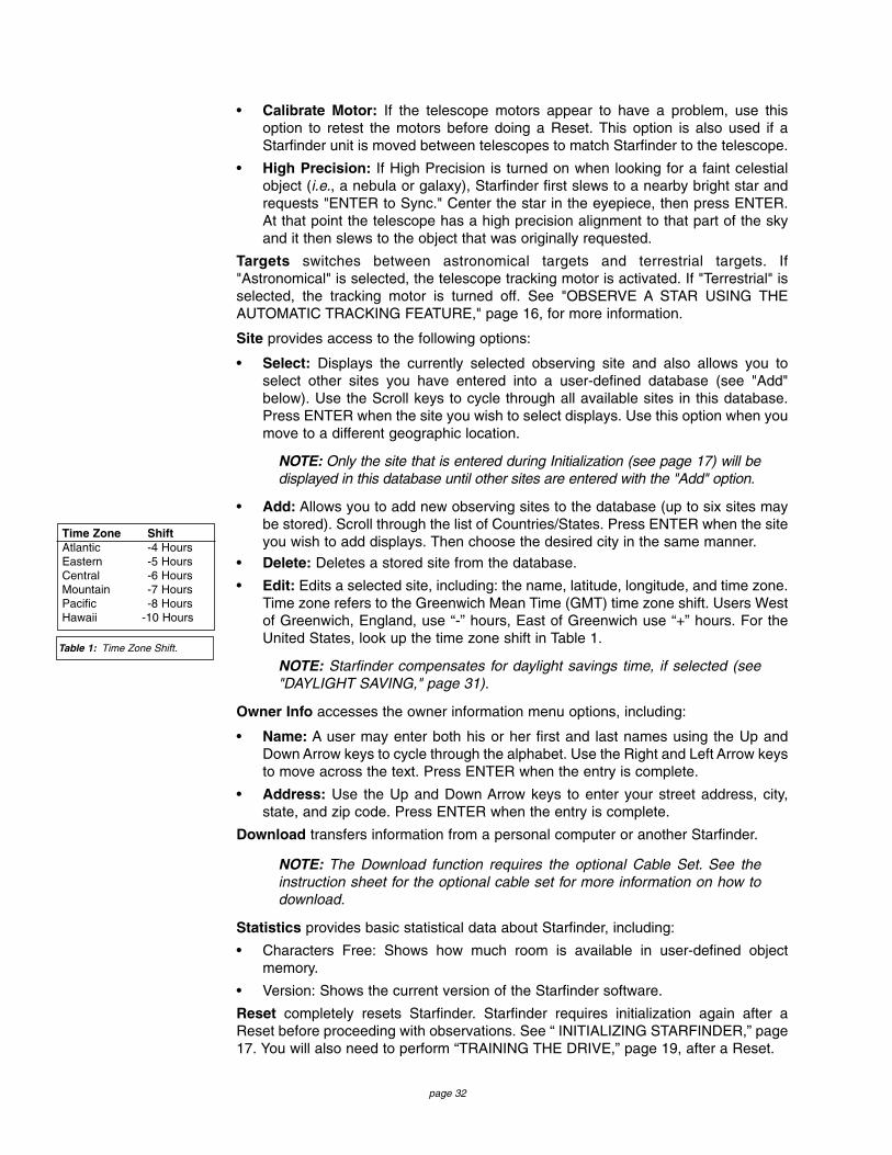
page 32
• Calibrate Motor: If the telescope motors appear to have a problem, use thisoption to retest the motors before doing a Reset. This option is also used if aStarfinder unit is moved between telescopes to match Starfinder to the telescope.
• High Precision: If High Precision is turned on when looking for a faint celestialobject (i.e., a nebula or galaxy), Starfinder first slews to a nearby bright star andrequests "ENTER to Sync." Center the star in the eyepiece, then press ENTER.At that point the telescope has a high precision alignment to that part of the skyand it then slews to the object that was originally requested.
Targets switches between astronomical targets and terrestrial targets. If"Astronomical" is selected, the telescope tracking motor is activated. If "Terrestrial" isselected, the tracking motor is turned off. See "OBSERVE A STAR USING THEAUTOMATIC TRACKING FEATURE," page 16, for more information.
Site provides access to the following options:
• Select: Displays the currently selected observing site and also allows you toselect other sites you have entered into a user-defined database (see "Add"below). Use the Scroll keys to cycle through all available sites in this database.Press ENTER when the site you wish to select displays. Use this option when youmove to a different geographic location.
NOTE: Only the site that is entered during Initialization (see page 17) will bedisplayed in this database until other sites are entered with the "Add" option.
• Add: Allows you to add new observing sites to the database (up to six sites maybe stored). Scroll through the list of Countries/States. Press ENTER when the siteyou wish to add displays. Then choose the desired city in the same manner.
• Delete: Deletes a stored site from the database.
• Edit: Edits a selected site, including: the name, latitude, longitude, and time zone.Time zone refers to the Greenwich Mean Time (GMT) time zone shift. Users Westof Greenwich, England, use “-” hours, East of Greenwich use “+” hours. For theUnited States, look up the time zone shift in Table 1.
NOTE: Starfinder compensates for daylight savings time, if selected (see"DAYLIGHT SAVING," page 31).
Owner Info accesses the owner information menu options, including:
• Name: A user may enter both his or her first and last names using the Up andDown Arrow keys to cycle through the alphabet. Use the Right and Left Arrow keysto move across the text. Press ENTER when the entry is complete.
• Address: Use the Up and Down Arrow keys to enter your street address, city,state, and zip code. Press ENTER when the entry is complete.
Download transfers information from a personal computer or another Starfinder.
NOTE: The Download function requires the optional Cable Set. See theinstruction sheet for the optional cable set for more information on how todownload.
Statistics provides basic statistical data about Starfinder, including:
• Characters Free: Shows how much room is available in user-defined objectmemory.
• Version: Shows the current version of the Starfinder software.
Reset completely resets Starfinder. Starfinder requires initialization again after aReset before proceeding with observations. See “ INITIALIZING STARFINDER,” page17. You will also need to perform “TRAINING THE DRIVE,” page 19, after a Reset.
Time Zone ShiftAtlantic -4 HoursEastern -5 HoursCentral -6 HoursMountain -7 HoursPacific -8 HoursHawaii -10 Hours
Table 1: Time Zone Shift.

page 33
PART 3: Caring for Your TelescopeCleaningThe lens or mirror surfaces should be cleaned as infrequently as possible. Front sur-face aluminized mirrors, in particular, should be cleaned only when absolutely neces-sary. In all cases, avoid touching any mirror surface. A little dust on the surface of amirror or lens causes negligible loss of performance and should not be considered rea-son to clean the surface. When lens or mirror cleaning does become necessary, usea camel’s hair brush or compressed air gently to remove dust. If the telescope’s dustcover is replaced after each observing session, cleaning of the optics will rarely berequired.
Mount and Tripod AdjustmentsEvery Meade 4504 Telescope equatorial mount and tripod is factory inspected forproper fit and function prior to shipment. It is unlikely that you will need to adjust ortighten these parts after receipt of the telescope. However, if the instrument receivedunusually rough handling in shipment, it is possible that some of these assemblies canbe loose. To make adjustments you will need a 1/2" or 11/16" socket or adjustable endwrench, a 5/64" hex wrench, and a Phillips-head screwdriver.
The equatorial mount has four main areas thatcan be adjusted: A loose polar shaft can be tight-ened by releasing a 5/64" hex set-screw that ison the side of the 11/16" polar shaft acorn capnut (3, Fig. 21), and then turning the 11/16"acorn cap nut clockwise to a firm feel, and thentightening the 5/64" hex set-screw. A looseAzimuth base (4, Fig. 21), can be tightened byturning the 11/16" Azimuth shaft bolt, locatedunderneath the mount and in between the threetripod legs, clockwise to a firm feel. The R.A. (1,Fig. 11), and Dec (12, Fig. 11) worm blockassemblies can have backlash removed byreleasing the two Phillips-head screws on eachassembly, applying pressure to the worm block against the worm gear, and then tight-ening the Phillips-head screws. Note that overtightening of any of the nuts, bolts, orscrews can inhibit the smooth rotating action of the axes and gears, and may result instripping the threads.
The tripod legs have 1/2" nuts (1, Fig. 21), and Phillips-head screws (2, Fig. 21) thatmay have backed off. Tighten to a firm feel for the most sturdy performance of the tele-scope.
DiagonalAssembly Diagonal Mirror
Focused Image
Primary Mirror
Primary Mirror-TiltScrews
Fig. 22: The Newtonian reflecting telescope.
1
2 2
3
4
Fig. 21: Maintenance adjustments.

page 34
Collimation (Alignment) of the OpticsYour telescope is optically aligned at the factory prior to shipment. It is unlikely that youwill need to align, or collimate, the optics after receipt of the instrument. However, ifthe telescope received unusually rough handling in shipment, it is possible that theoptics must be re-aligned for best optical performance. Take the time to familiarizeyourself with the following collimation procedure, so that you will recognize a properlycollimated instrument and can adjust the collimation yourself, if necessary.
Correct collimationThe properly collimated (aligned) mirror system in the Meade 4504 Telescope assuresthe sharpest images possible. This occurs when the primary mirror and diagonal mir-ror are tilted so that the focused image (Fig. 22) falls directly through the center of thefocuser drawtube. These mirror tilt adjustments are made with the diagonal assembly(Fig. 22) and the primary mirror cell (Fig. 22), and will be discussed later.
To inspect the view of the mirror collimation, look down the focuser drawtube with theeyepiece removed. The edge of the focuser drawtube will frame the reflections of theprimary mirror with the 3 mirror clips (2, Fig. 25), the diagonal mirror (3, Fig. 25), thespider vanes (4, Fig. 25), and your eye (5, Fig. 25). Properly aligned, all of thesereflections will appear concentric (i.e. centered) as illustrated in Fig. 25. Any deviationfrom the concentric reflections will require adjustments to the diagonal assembly (Fig.23), and/or the primary mirror cell (Fig. 24).
Spider vane adjustmentsIf the diagonal mirror (1, Fig. 26) is left or right of center within the drawtube (2, Fig.26), loosen the spider vane adjustment/lock knobs (1, Fig. 23) located on the outsidesurface of the main tube and slide the entire diagonal assembly up or down the tubealong the slotted holes, until the diagonal mirror is centered in the drawtube. If thediagonal mirror (1, Fig. 26) is above or below of center within the drawtube, thread inone of the spider vane adjustment/ lock knobs while unthreading the other. Only makeadjustments to two knobs at a time until the diagonal mirror is in the drawtube. Whenthe spider vane is correctly positioned, it will look like Fig. 27 (the diagonal mirror ismisaligned).
Diagonal holder adjustmentsIf the diagonal mirror (1, Fig. 27) is centered in the drawtube (2, Fig. 27), but the pri-mary mirror is only partially visible in the reflection (3, Fig. 27), the three Phillips-headdiagonal tilt screws (2, Fig. 23) must be unthreaded slightly to the point of where youcan rotate the diagonal holder (3, Fig. 23) from side-to-side by grasping the diagonalholder with your hand and rotating until you see the primary mirror become as cen-tered in the reflection of the diagonal mirror as possible. Once you are at the best posi-tion, thread in the three Phillips-head diagonal tilt screws to lock the rotational posi-tion. Then, if necessary, make adjustments to these three Phillips-head screws to
2
1
3
Fig. 23: Diagonal assembly.
3 2
Fig. 24: Primary mirror cell.

page 35
refine the tilt-angle of the diagonal mirror until the entire primary mirror can be seencentered within the diagonal mirror reflection. When the diagonal mirror is correctlyaligned, it will look like Fig. 28 (the primary mirror is shown out of alignment).
Primary mirror adjustmentsIf the diagonal mirror (1, Fig. 28) and the reflection of the primary mirror (2, Fig. 28)appear centered within the drawtube (3, Fig. 28), but the reflection of your eye and thereflection of the diagonal mirror (4, Fig. 28) appear off-center, you will need to adjustthe primary mirror tilt Phillips-head screws of the primary mirror cell (3, Fig. 24). Theseprimary tilt screws are located behind the primary mirror, at the lower end of the maintube (Fig. 22). To adjust the primary mirror tilt screws, first unscrew several turns thethree hex-head primary mirror cell locking screws (2, Fig. 24) that are next to each pri-mary mirror tilt Phillips-head screw. Then by trial-and-error, turn the primary mirror tiltPhillips-head screws (3, Fig. 24) until you develop a feel for which way to turn eachscrew to center the reflection of your eye. Once centered, as in Fig. 25, turn the threehex-head primary mirror cell locking screws (2, Fig. 24) to relock the tilt-angle adjust-ment.
4
5
3
31
2
2
2
2
2
1
34
1
1
Fig. 27: Diagonal mirror misalignment. Fig. 28: Primary mirror misalignment.
Fig. 25: Correct collimation. Fig. 26: Spider vane misalignment.

page 36
Star testing the collimationWith the collimation performed, you will want to test the accuracy of the alignment ona star. Use the H 25mm eyepiece and point the telescope at a moderately bright (sec-ond or third magnitude) star, then center the star image in the telescope’s field-of-view.With the star centered, follow the method below:
• Bring the star image slowly out of focus until one or more rings are visible aroundthe central disc. If the collimation was performed correctly, the central star disk andrings will be concentric circles, with a dark spot dead center within the out-of-focusstar disk (this is the shadow of the secondary mirror), as shown in C, Fig. 29. (Animproperly aligned telescope will reveal elongated circles (A, Fig. 29), with an off-center dark shadow.)
• If the out-of-focus star disk appears elongated (B, Fig. 29), you will need to adjustthe primary mirror Phillips-head tilt screws of the primary mirror cell (3, Fig. 24).
• To adjust the primary mirror tilt screws (3, Fig. 24), first unscrew several turns thethree hex-head primary mirror cell locking screws (2, Fig. 24), to allow free turningmovement of the tilt knobs.
• As you make adjustments to the primary mirror tilt screws (3, Fig. 24), you willnotice that the out-of-focus star disk image will move across the eyepiece field.Choose one of the three primary mirror tilt screws that will move the star diskimage to the center of the eyepiece field.
• Repeat this process as many times as necessary until the out-of-focus star diskappears as in C, Fig. 29, when the star disk image is in the center of the eyepiecefield.
• With the star testing of the collimation complete, tighten the three hex-headprimary mirror locking screws (2, Fig. 24).
Fig. 29: Collimation.
A B C

page 37
MODEL 4504 TELESCOPE SPECIFICATIONS
Optical design ................................................................Newtonian ReflectorClear aperture ..............................................................114mm (4.5”)Focal length ....................................................................910mmFocal ratio (photographic speed) ..................................f/8Resolving power ............................................................1.0 arc secsMulti-coatings on objective lens ....................................StandardLimiting visual stellar magnitude (approx.) ....................12.4Image scale ..................................................................1.6°/inchMaximum practical visual power ..................................325XOptical tube dimensions
(dia. x length) ..........................................................14cm x 86.4cm (5.5” x 34”)Eyepieces
Modified Achromatic ..............................................H 25mm (0.965” O.D.)Modified Achromatic ..............................................H 12.5mm (0.965” O.D.)Modified Achromatic ..............................................SR 4mm (0.965” O.D.)Barlow ....................................................................3x magnification
Telescope mounting........................................................German equatorial mountSetting circle diameters ..........................................6.2cm (2.45")Input voltage ..........................................................12-volts DCMotor Drive System ................................................DC servo motors with encoders, both axes
Slow-Motion Controls ....................................................Electric, 7 speeds, both axesHemispheres of operation ..............................................North and South, switchableMaterials
Tube body ..............................................................AluminumMounting ................................................................Die-cast aluminum
Telescope net weight: (telescope only, without batteries, eyepieces)................10.5 kg (23 lbs.)Telescope shipping weight (telescope, accessories, instruction manual, packing) ..14 kg (31 lbs.)Battery Life (approx.)
with Starfinder ........................................................20 hrs.
STARFINDER SPECIFICATIONSProcessor ......................................................................68HC11, 8MHzFlash Memory ................................................................512KB, reloadableKeypad ..........................................................................10 key Display............................................................................2 line, 16 character LCDBacklight ........................................................................Red LEDCoil Cord ........................................................................24"
STARFINDER DIMENSIONSLength ............................................................................14.2cm (5.60")Width (LCD end) ............................................................78.0cm (3.08")Width (Connector end) ..................................................53.5cm (2.10")Depth ..............................................................................23.5cm (0.93")

page 38
APPENDIX A: Calculating Eyepiece PowerThe power, or magnification of the telescope depends on two optical characteristics:the focal length of the main telescope and the focal length of the eyepiece used dur-ing a particular observation. The focal length of the 4504 telescope is fixed at 910mm.To calculate the power in use with a particular eyepiece, divide the focal length of theeyepiece into the focal length of the main telescope. E.g., using the H 25mm eyepiecesupplied with the telescope, the power is calculated as follows:
Power = telescope focal length 910mm = 36xeyepiece focal length 25mm
The maximum practical magnification is determined by the nature of the object beingobserved and, most importantly, by the prevailing atmospheric conditions. Generallypowers of perhaps 35x to 175x will be useful most often, consistent with high imageresolution. When unsteady air conditions prevail (as witnessed by rapid “twinkling” ofthe stars), extreme high-power results in “empty magnification,” where the object detailobserved is actually diminished by the excessive power.
The 3x Barlow lens included with your telescope triples the eyepiece magnification. Tocalculate the power of an eyepiece used with a Barlow lens, multiply the eyepiecepower by the Barlow value. E.g., using the H 25mm eyepiece, the power or magnifi-cation of the 4504 telescope (as calculated in the example above) is 36x and theBarlow value is 3x. The total power using the Barlow lens is:
Total power = eyepiece power x Barlow value = 36 x 3 = 108x
To install the Barlow lens, first place the Barlow lens into the focuser assembly(remove the focuser dustcap, if necessary), followed by the eyepiece (Fig. 30).Tighten the Barlow thumbscrews and the focuser thumbscrews to a firm feel only.
=
Fig. 30: Insert Barlow into focuserassembly.
Eyepiece
Barlow
Thumbscrew
Thumbscrew
Focus knob
FocuserAssembly

page 39
APPENDIX B: Terrestrial Viewing, Celestial Movement,and Polar Alignment
Terrestrial ViewingThe 4504 is an excellent, high-resolution terrestrial (land) telescope. Viewing terrestrialobjects requires looking along the Earth's surface through heat waves. These heatwaves often cause degradation of image quality. Low power eyepieces, like the H 25mmeyepiece, magnify these heat waves less than higher power eyepieces. Therefore, lowpower eyepieces provide a steadier, higher quality image. If the image is fuzzy or ill-defined, reduce to a low-power, where the heat waves do not have such an effect onimage quality. Observing in early morning hours, before the ground has built up internalheat, produces better viewing conditions than during late-afternoon hours.
Astronomical ObservingUsed as an astronomical instrument, your telescope has many optical and electro-mechanical capabilities. It is in astronomical applications where the high level of opti-cal performance is readily visible. The range of observable astronomical objects is,with minor qualification, limited only by the observer’s motivation.
Polar AlignmentLunar or planetary photography requires that the telescope be Polar aligned. In PolarAlignment, the telescope is oriented so that the horizontal and vertical axes of the tele-scope are lined up with the celestial coordinate system.
In order to understand Polar Alignment, it is essential to have an understanding of howand where to locate celestial objects as they move across the sky. This section pro-vides a basic introduction to the terminology of Polar-aligned astronomy, and includesinstructions for finding the celestial pole and for finding objects in the night sky usingDeclination and Right Ascension.
Understanding Celestial Movements and CoordinatesUnderstanding where to locate celestial objects and how those objects move acrossthe sky is fundamental to enjoying the hobby of astronomy. Most amateur astronomersadopt the simple practice of “star-hopping” to locate celestial objects by using starcharts or astronomical software which identify bright stars and star patterns (constel-lations) that serve as “road maps” and “landmarks” in the sky. These visual referencepoints guide amateur astronomers in their search for astronomical objects.
Understanding How Astronomical Objects MoveDue to the Earth’s rotation, celestial bodies appear to move from East to West in acurved path through the sky. The path they follow is known as their line of RightAscension (R.A.). The angle of the path that they follow is known as their line ofDeclination (Dec). The system of R.A. and Dec is analogous to the Earth-based coor-dinate system of latitude and longitude. Like Earth, imaginary lines have been drawnon the celestial sphere to form a coordinate grid. Celestial object positions on theEarth's surface are specified by their latitude and longitude.
Understanding Celestial CoordinatesCelestial objects are mapped according to the R.A. and Dec coordinate system on the“celestial sphere” (Fig. 31), the imaginary sphere on which all stars appear to beplaced. The Poles of the celestial coordinate system are defined as those two pointswhere the Earth's rotational axis, if extended to infinity, North and South, intersect thecelestial sphere. Thus, the North Celestial Pole is that point in the sky where an exten-sion of the Earth's axis through the North Pole intersects the celestial sphere. In fact,this point in the sky is located near the North Star, or Polaris.

page 40
On the surface of the Earth,“lines of longitude” are drawnbetween the North and SouthPoles. Similarly, “lines of latitude”are drawn in an East-West direc-tion, parallel to the Earth's equa-tor. The celestial equator is sim-ply a projection of the Earth'sequator onto the celestialsphere. Just as on the surface ofthe The celestial equivalent toEarth latitude is called“Declination,” or simply “Dec.” Itis measured in degrees, minutesor seconds north ("+") or south("-") of the celestial equator. Thusany point on the celestial equator(which passes, for example,through the constellations Orion, Virgo and Aquarius) is specified as having 0°0'0"Dec. The Dec of the star Polaris, located very near the North Celestial Pole, is +89.2°.
The celestial equivalent to Earth longitude is called “Right Ascension,” or “R.A.” It ismeasured in hours, minutes, and seconds from an arbitrarily defined “zero” line of R.A.passing through the constellation Pegasus. R.A. coordinates range from 0hr0min0secup to (but not including) 24hr0min0sec. Thus there are 24 primary lines of R.A., locat-ed at 15 degree intervals along the celestial equator. Objects located further and fur-ther east of the prime (0h0m0s) R. A. grid line carry increasing R.A. coordinates.
With all celestial objects therefore capable of being specified in position by their celes-tial coordinates of R.A. and Dec, the task of finding objects (in particular, faint objects)in the telescope is vastly simplified. The setting circles, R.A. (15, Fig. 2a) and Dec (9,Fig. 2a)of the Meade 4504 Telescope may be dialed, in effect, to read the object coor-dinates, and the object can be found without resorting to visual location techniques.However, these setting circles may be used to advantage only if the telescope is firstproperly aligned with the Celestial Pole.
Lining Up with the Celestial PoleObjects in the sky appear to revolve around the Celestial Pole (actually, celestial objectsare essentially “fixed,” and their apparent motion is caused by the Earth’s axial rotation).During any 24 hour period, stars make one complete revolution about the pole, makingconcentric circles with the pole at the center. By lining up the telescope’s polar axis withthe North Celestial Pole (or, for observers located in Earth’s Southern Hemisphere, withthe South Celestial Pole), astronomical objects may be followed, or tracked, by movingthe telescope about one axis, the polar axis.
Virtually all of the required tele-scope tracking will be in R.A. (ifthe telescope were perfectlyaligned with the pole, no Dectracking of stellar objects wouldbe required). For the purposes ofcasual visual telescopic obser-vations, lining up the telescope’spolar axis to within a degree ortwo of the pole is more than suf-ficient.
141516171819
20 21 22 23 0 1
12 11 10 9 87
56
432
13
Earth’sRotation
0 Dec.
South Celestial Pole
Right Ascension
Star
Celestial Equator
-90 Dec.
+90 Dec.North Celestial Pole(Vicinity of Polaris)
Declination
1
2
Fig. 31: Celestial sphere.
PolarisLittle Dipper
Big Dipper Cassiopeia
Fig. 32: Locating Polaris.

page 41
Using Setting CirclesThe setting circles of the Polar aligned equatorial mount can be used to locate faintcelestial objects not easily found by direct visual observation. To use the setting cir-cles, follow this procedure:
• Use a star chart or star atlas, and look up the celestial coordinates, RightAscension and Declination (R.A. and Dec), of an easy-to-find bright star that iswithin the general vicinity of the faint object you wish to locate.
• Center the determined bright star in the telescope’s field of view.
• Manually turn the R.A. setting circle (15, Fig. 2a) to read the R.A. of the object nowin the telescope’s eyepiece.
• The setting circles are now calibrated (the Dec setting circle (9, Fig. 2a) is factorycalibrated). To locate a nearby faint object using the setting circles, determine thefaint object’s celestial coordinates from a star chart and move the telescope inR.A. and Dec until the setting circles read the R.A. and Dec of the object you areattempting to locate. If the above procedure has been carefully performed, thefaint object will now be in the field of a low power eyepiece.
• The R.A. setting circle must be manually re-calibrated on the current R. A. of a starevery time the telescope is set up, and reset to the centered object’s R.A.coordinate before moving to a new R.A. coordinate setting. The R.A. setting circlehas two sets of numbers. The inner set is for Southern hemisphere use while theouter set (the set closest to the R.A. gear) is for use by observers located Northof the Earth’s equator (e.g., in North America and Europe).
Two-Star Polar AlignmentBesides One-Star Polar Alignment which was covered earlier in this manual (see"ALIGNING YOUR TELESCOPE USING STARFINDER," page 20), another type ofalignment, Two-Star Polar Alignment, is also available.
Two-Star Polar Alignment requires some knowledge of the night sky. Starfinder pro-vides a database of bright stars and two stars from this database are chosen by theobserver for alignment. The rest of the alignment procedure is identical to One-StarPolar Alignment.
1. Perform steps 1 through 4 as described in the "ALIGN YOUR TELESCOPEUSING STARFINDER," page 20.
2 . Starfinder displays a database of stars for the observer to choose from. Use theScroll keys to scroll to a star that you wish to align upon. Select a star that you caneasily locate in the night sky.
3. Press ENTER. The telescope slews to the star for alignment. Use the Arrow keysto move the telescope until the star is visible and centered in the eyepiece.
4. Press ENTER. Repeat the procedure for the second alignment star. The telescopeis aligned and you are now ready to use Starfinder's GO TO capabilities for a nightof observing.

APPENDIX C: Using Starfinder to Enter CelestialCoordinates Although Starfinder's database contains more than 1400 objects (stars, nebulae,planets, etc.) that you can observe, you may eventually want to view objects that arenot part of the database. Starfinder provides a feature that allows you to enter anobject's R.A and Dec coordinates in the "User: Objects" option of Starfinder's Objectmenu, and then will automatically slew the telescope to the user-entered coordinates.
In order to use this menu option, you first need to look up the R.A and Dec coordi-nates of the object or objects you wish to observe. Check out your local library, com-puter store, or bookstore for astronomy books, CD Roms, or magazines (such as Sky& Telescope or Astronomy), to find coordinates of celestial objects. A list of the coor-dinates of 14 common stars are printed at the end of this manual; see "STAR LOCA-TOR," page 46.
The objects/coordinates you enter become part of your own permanent database,called "User Objects." You may use this menu to view these object as often as youlike, but the objects' coordinates just need to be entered once.
To enter coordinates of an object into the "User: Objects" option of the Objectmenu:1. Make sure Starfinder has been initialized (see "INITIALIZING STARFINDER,"
page 17) and the telescope has been aligned (see "ALIGN YOUR TELESCOPEUSING STARFINDER," page 20).
2. After the telescope is aligned, "Select Item: Object" displays. (If necessary, usethe Scroll keys to scroll through the menus, as previously described, to find thisoption.) Press ENTER.
3. "Object: Solar System" displays. Keep pressing the Scroll Up key until "Object:User Object" displays and press ENTER.
4. "User Object: Select" displays. Press the Scroll Down key once. "User Object:Add" displays. Press ENTER.
5. "Name" displays on the top line and a blinking cursor on the second line. Use theArrow keys (as previously described) to enter the name of the object you wish toadd to the database. When you are finished, press ENTER.
6. "Right Asc.: +00.00.0" displays. Use the Arrow keys to enter the digits for theRight Ascension (R.A.) coordinate of your object. If necessary, use the Scroll Keysto change "+" to "-." When you are finished, press ENTER.
7. "Declination: +00°.00'" displays. Use the Arrow keys to enter the digits for theDeclination (Dec) coordinate of your object. If necessary, use the Scroll Keys tochange "+" to "-." When you are finished, press ENTER.
8. Starfinder then prompts you to enter the Size of the object. This step is optional.Use the Arrow keys to enter this information, if so desired, and press ENTER togo to the next display. If you do not wish to enter this information, simply pressENTER.
9. Starfinder then prompts you to enter the Magnitude of the object. This step is alsooptional. Use the Arrow keys to enter this information, if so desired, and pressENTER to go to the next display. "User Object: Add" displays again.
To GO TO a user-entered object:
1. With "User Object: Add" displayed, press the Scroll Up key once. "User Object:Select" displays. Press ENTER.
2. Use the Scroll keys (if necessary) to scroll to the desired object. Press ENTER.
3. The name of the object and the R.A. and Dec coordinates display.
4. Press GO TO and the telescope slews to the object.
page 42

page 43
APPENDIX D: Helpful Charts
Latitude Chart for Major Cities of the WorldTo aid in the Polar Alignment procedure (see "TO POLAR ALIGN THE TELESCOPE," page 15), latitudesof major cities around the world are listed below. To determine the latitude of an observing site not listedon the chart, locate the city closest to your site. Then follow the procedure below:
Northern Hemisphere observers (N): If the site is over 70 miles (110 km) North of the listed city, add onedegree for every 70 miles. If the site is over 70 miles South of the listed city, subtract one degree per 70miles.
Southern Hemisphere observers (S): If the site is over 70 miles North of the listed city, subtract onedegree for every 70 miles. If the site is over 70 miles South of the listed city, add one degree per 70 miles.
UNITED STATESCity State LatitudeAlbuquerque New Mexico 35° NAnchorage Alaska 61° NAtlanta Georgia 34° NBoston Massachusetts 42° NChicago Illinois 42° NCleveland Ohio 41° NDallas Texas 33° NDenver Colorado 40° NDetroit Michigan 42° NHonolulu Hawaii 21° NJackson Mississippi 32° NKansas City Missouri 39° NLas Vegas Nevada 36° NLittle Rock Arkansas 35° NLos Angeles California 34° NMiami Florida 26° NMilwaukee Wisconsin 46° NNashville Tennessee 36° NNew Orleans Louisiana 30° NNew York New York 41° NOklahoma City Oklahoma 35° NPhiladelphia Pennsylvania 40° NPhoenix Arizona 33° NPortland Oregon 46° NRichmond Virginia 37° NSalt Lake City Utah 41° NSan Antonio Texas 29° NSan Diego California 33° NSan Francisco California 38° NSeattle Washington 47° NWashington District of Columbia 39° NWichita Kansas 38° N
EUROPECity Country LatitudeAmsterdam Netherlands 52° NAthens Greece 38° NBern Switzerland 47° NCopenhagen Denmark 56° NDublin Ireland 53° NFrankfurt Germany 50° NGlasgow Scotland 56° NHelsinki Finland 60° NLisbon Portugal 39° N
EUROPE (cont'd)City Country LatitudeLondon England 51° NMadrid Spain 40° NOslo Norway 60° NParis France 49° NRome Italy 42° NStockholm Sweden 59° NVienna Austria 48° NWarsaw Poland 52° N
SOUTH AMERICACity Country LatitudeAsuncion Paraguay 25° SBrasilia Brazil 24° SBuenos Aires Argentina 35° SMontevideo Uruguay 35° SSantiago Chile 34° S
ASIACity Country LatitudeBeijing China 40° NSeoul South Korea 37° NTaipei Taiwan 25° NTokyo Japan 36° NVictoria Hong Kong 23° N
AFRICACity Country LatitudeCairo Egypt 30° NCape Town South Africa 34° SRabat Morocco 34° NTunis Tunisia 37° NWindhoek Namibia 23° S
AUSTRALIACity State LatitudeAdelaide South Australia 35° SBrisbane Queensland 27° SCanberra New South Wales 35° SAlice Springs Northern Territory 24° SHobart Tasmania 43° SPerth Western Australia 32° SSydney New South Wales 34° SMelbourne Victoria 38° S
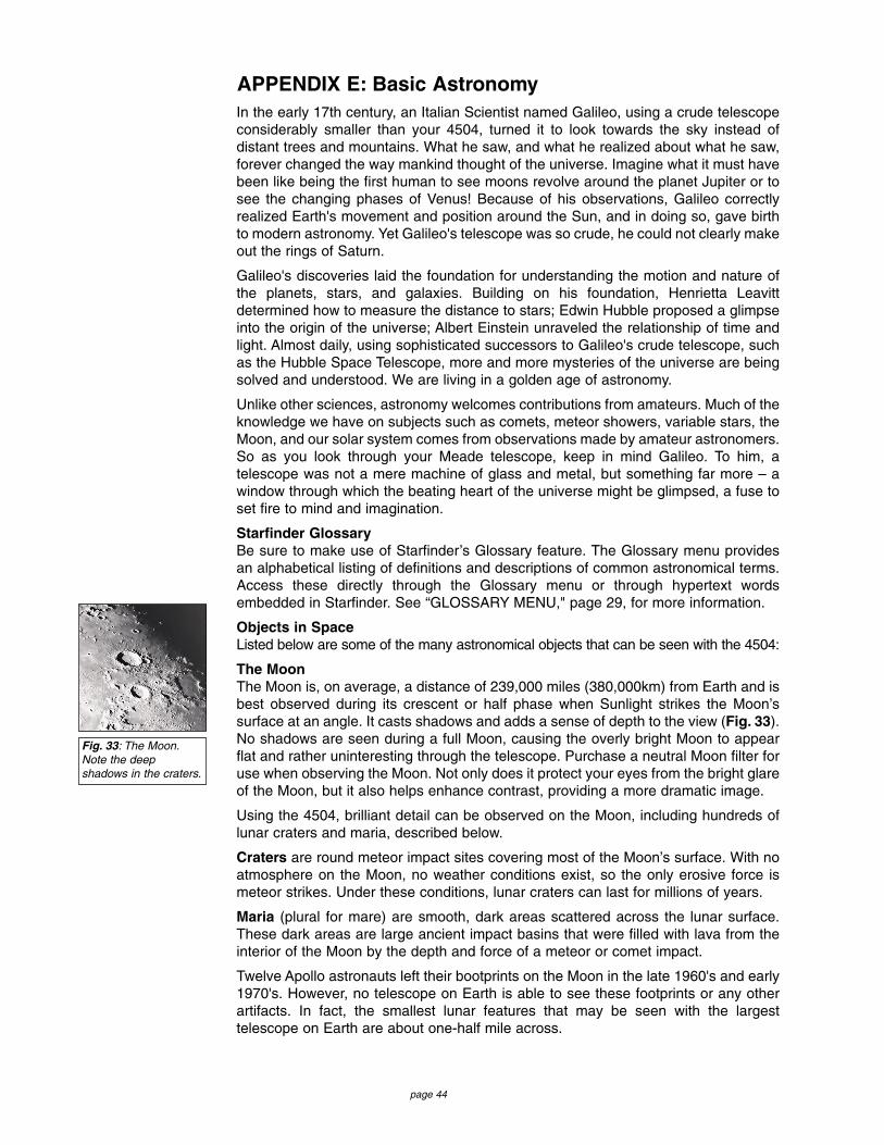
page 44
In the early 17th century, an Italian Scientist named Galileo, using a crude telescopeconsiderably smaller than your 4504, turned it to look towards the sky instead ofdistant trees and mountains. What he saw, and what he realized about what he saw,forever changed the way mankind thought of the universe. Imagine what it must havebeen like being the first human to see moons revolve around the planet Jupiter or tosee the changing phases of Venus! Because of his observations, Galileo correctlyrealized Earth's movement and position around the Sun, and in doing so, gave birthto modern astronomy. Yet Galileo's telescope was so crude, he could not clearly makeout the rings of Saturn.
Galileo's discoveries laid the foundation for understanding the motion and nature ofthe planets, stars, and galaxies. Building on his foundation, Henrietta Leavittdetermined how to measure the distance to stars; Edwin Hubble proposed a glimpseinto the origin of the universe; Albert Einstein unraveled the relationship of time andlight. Almost daily, using sophisticated successors to Galileo's crude telescope, suchas the Hubble Space Telescope, more and more mysteries of the universe are beingsolved and understood. We are living in a golden age of astronomy.
Unlike other sciences, astronomy welcomes contributions from amateurs. Much of theknowledge we have on subjects such as comets, meteor showers, variable stars, theMoon, and our solar system comes from observations made by amateur astronomers.So as you look through your Meade telescope, keep in mind Galileo. To him, atelescope was not a mere machine of glass and metal, but something far more – awindow through which the beating heart of the universe might be glimpsed, a fuse toset fire to mind and imagination.
Starfinder GlossaryBe sure to make use of Starfinder’s Glossary feature. The Glossary menu providesan alphabetical listing of definitions and descriptions of common astronomical terms.Access these directly through the Glossary menu or through hypertext wordsembedded in Starfinder. See “GLOSSARY MENU," page 29, for more information.
Objects in SpaceListed below are some of the many astronomical objects that can be seen with the 4504:
The MoonThe Moon is, on average, a distance of 239,000 miles (380,000km) from Earth and isbest observed during its crescent or half phase when Sunlight strikes the Moon’ssurface at an angle. It casts shadows and adds a sense of depth to the view (Fig. 33).No shadows are seen during a full Moon, causing the overly bright Moon to appearflat and rather uninteresting through the telescope. Purchase a neutral Moon filter foruse when observing the Moon. Not only does it protect your eyes from the bright glareof the Moon, but it also helps enhance contrast, providing a more dramatic image.
Using the 4504, brilliant detail can be observed on the Moon, including hundreds oflunar craters and maria, described below.
Craters are round meteor impact sites covering most of the Moon’s surface. With noatmosphere on the Moon, no weather conditions exist, so the only erosive force ismeteor strikes. Under these conditions, lunar craters can last for millions of years.
Maria (plural for mare) are smooth, dark areas scattered across the lunar surface.These dark areas are large ancient impact basins that were filled with lava from theinterior of the Moon by the depth and force of a meteor or comet impact.
Twelve Apollo astronauts left their bootprints on the Moon in the late 1960's and early1970's. However, no telescope on Earth is able to see these footprints or any otherartifacts. In fact, the smallest lunar features that may be seen with the largesttelescope on Earth are about one-half mile across.
APPENDIX E: Basic Astronomy
Fig. 33: The Moon.Note the deepshadows in the craters.

page 45
PlanetsPlanets change positions in the sky as they orbit around the Sun. To locate the planetson a given day or month, consult a monthly astronomy magazine, such as Sky andTelescope or Astronomy. Listed below are the best planets for viewing through the4504.
Venus is about nine-tenths the diameter of Earth. As Venus orbits the Sun, observerscan see it go through phases (crescent, half, and full) much like those of the Moon.The disk of Venus appears white as Sunlight is reflected off the thick cloud cover thatcompletely obscures any surface detail.
Mars is about half the diameter of Earth, and appears through the telescope as a tinyreddish-orange disk. It may be possible to see a hint of white at one of the planet’sPolar ice caps. Approximately every two years, when Mars is closest to Earth in itsorbit, additional detail and coloring on the planet's surface may be visible.
Jupiter is the largest planet in our solar system and is 11 times the diameter of Earth.The planet appears as a disk with dark lines stretching across the surface. These linesare cloud bands in the atmosphere. Four of Jupiter’s 16 moons (Io, Europa,Ganymede, and Callisto) can be seen as “star-like” points of light when using eventhe lowest magnification. These moons orbit Jupiter so that the number of moonsvisible on any given night changes as they circle around the giant planet.
Saturn is nine times the diameter of Earth and appears as a small, round disk withrings extending out from either side. In 1610, Galileo, the first person to observeSaturn through a telescope, did not understand that what he was seeing were rings.Instead, he believed that Saturn had “ears.” Saturn’s rings are composed of billions ofice particles ranging in size from a speck of dust to the size of a house. The majordivision in Saturn's rings, called the Cassini Division, is occasionally visible throughthe 4504. Titan, the largest of Saturn’s 18 moons can also be seen as a bright, star-like object near the planet.
Deep-Sky ObjectsStar charts can be used to locate constellations, individual stars and deep-skyobjects. Examples of various deep-sky objects are given below:
Stars are large gaseous objects that are self-illuminated by nuclear fusion in theircore. Because of their vast distances from our solar system, all stars appear aspinpoints of light, irrespective of the size of the telescope used.
Nebulae are vast interstellar clouds of gas and dust where stars are formed. Mostimpressive of these is the Great Nebula in Orion (M42), a diffuse nebula that appearsas a faint wispy gray cloud. M42 is 1600 light years from Earth.
Open Clusters are loose groupings of young stars, all recently formed from the samediffuse nebula. The Pleiades is an open cluster 410 light years away. Through the4504, numerous stars are visible.
Constellations are large, imaginary patterns of stars believed by ancient civilizationsto be the celestial equivalent of objects, animals, people, or gods. These patterns aretoo large to be seen through a telescope. To learn the constellations, start with aneasy grouping of stars, such as the Big Dipper in Ursa Major. Then, use a star chartto explore across the sky.
Galaxies are large assemblies of stars, nebulae, and star clusters that are bound bygravity. The most common shape is spiral (such as our own Milky Way), but galaxiescan also be elliptical, or even irregular blobs. The Andromeda Galaxy (M31) is theclosest spiral-type galaxy to our own. This galaxy appears fuzzy and cigar-shaped. Itis 2.2 million light years away in the constellation Andromeda, located between thelarge “W” of Cassiopeia and the great square of Pegasus.
Fig. 35: Saturn hasthe most extensivering structure in ourSolar System.
Fig. 36: ThePleiades is one ofthe most beautifulopen clusters.
Fig. 34: Jupiter andits four largestmoons. The moonscan be observed ina different positionevery night.

page 46
A Roadmap to the StarsThe night sky is filled with wonder andintrigue. You too can enjoy exploringthe universe simply by following a fewpointers on a roadmap to the stars.
First, find the Big Dipper which is part ofthe constellation Ursa Major. The BigDipper is usually easy to locate yearround in North America.
Extending directly out from the far sideof the Big Dipper’s cup is theconstellation Orion. One of the mostexquisite areas of the winter sky, Orionis distinguished by Orion’s belt, which ismarked by three stars in a row. TheOrion Nebula is located South of thebelt and is one of the most observeddeep-sky objects by amateurastronomers.
Extending from the “pointer stars” of theBig Dipper’s cup is Polaris, the North Star. Extending from Polaris is the Great Squareshared by the constellations Pegasus and Andromeda.
The Summer Triangle is a notable region in the sky to the left of the handle of the BigDipper. The triangle is made up of three very bright stars: Vega, Deneb, and Altair.
By drawing an imaginary line outward from the handle of the Big Dipper, you reachthe southern constellation “Scorpius.” Scorpius curves to the left like the tail of ascorpion in the sky, or like letter “J.”
Amateur astronomers commonly use the phrase “Arc to Arcturus and spike to Spica”to refer to the area directly off the arc in the handle of the Big Dipper. Follow the arcto Arcturus, the second brightest star in the Northern Hemisphere, then spike down toSpica, the 16th brightest star in the sky.
Star LocatorThe chart below lists bright stars with their R.A. and Dec coordinates, along with theNorthern Hemisphere season when these stars are prominent in the night sky. Thislist aids the observer to find alignment stars at various times of the year. For example,if it is a midsummer evening in the Northern Hemisphere, Deneb in the constellationCygnus would be an excellent alignment star, while Betelgeuse could not be usedbecause it is in the winter constellation Orion and thus, below the horizon.
Season Star Name Constellation R.A. Dec
Spring Arcturus Bootes 14h16m 19° 11"Spring Regulus Leo 10h09m 11° 58"Spring Spica Virgo 13h25m -11° 10"
Summer Vega Lyra 18h37m 38° 47"Summer Deneb Cygnus 20h41m 45° 17"Summer Altair Aquila 19h51m 08° 52"Summer Antares Scorpius 16h30m -26° 26"
Fall Markab Pegasus 23h05m 15° 12"Fall Fomalhaut Pisces Austrinus s22h58m -29° 38"Fall Mira Cetus 02h19m -02° 58"
Winter Rigel Orion 05h15m -08° 12"Winter Betelgeuse Orion 05h55m 07° 25"Winter Sirius Canis Major 06h45m -16° 43" Winter Aldebaran Taurus 04h35m 16° 31"
Orion
GeminiAndromeda
Pegasus
Aquila
Lyra
Cygnus
Boötes
Virgo
Scorpius
Leo“Big Dipper”
“SummerTriangle”
Polaris
Betelgeuse
Rigel
Pollux
Castor
“Sickle”
RegulusDeneb
Vega
Antares
Altair Arcturus
Spica
Fig. 37: Roadmap to the stars.

Meade Limited WarrantyEvery Meade telescope, spotting scope, and binocular is warranted by Meade Instruments Corp. (MIC) tobe free of defects in materials and workmanship for a period of ONE YEAR from date of original retailpurchase in the U.S.A. MIC will repair or replace the product, or part thereof, found upon inspection by MICto be defective, provided the defective part or product is returned to MIC, freight prepaid, with proof ofpurchase. This warranty applies to the original purchaser only and is non-transferable. Meade productspurchased outside North America are not included in this warranty, but are covered under separatewarranties issued by Meade International Distributors.
RGA Number Required: Prior to the return of any product or part, a Return Goods Authorization (RGA)number must be obtained by writing to MIC or by calling 949-451-1450. Each returned part or product mustinclude a written statement detailing the nature of the claimed defect, as well as the owner’s name, address,phone number, and a copy of the original sales invoice.
This warranty is not valid in cases where the product has been abused or mishandled, where unauthorizedrepairs have been attempted or performed, or where depreciation of the product is due to normal wear-and-tear. MIC specifically disclaims special, indirect, or consequential damages or lost profit, which may resultfrom a breach of this warranty. Any implied warranties which cannot be disclaimed are hereby limited to aterm of one year from the date of purchase by the original retail purchaser.
This warranty gives you specific rights. You may have other rights which vary from state to state.
MIC reserves the right to change product specifications or to discontinue products without prior notice.
This warranty supersedes all previous Meade product warranties.

0600 14-7010-04
A D V A N C E D P R O D U C T S D I V I S I O N
Meade Instruments CorporationWorld’s Leading Manufacturer of Astronomical Telescopes for the Serious Amateur6001 Oak Canyon, Irvine, California 92618 � (949) 451-1450FAX: (949) 451-1460 � www.meade.com © 2000