March 10, 20041 Iris Recognition Instructor: Natalia Schmid BIOM 426: Biometrics Systems.
INSTRUCTION MANUALBinocular Indirect OphthalmoMicroscope
i / ii
Notes on this instruction manual
Thank you for your purchase and the trust you have placed in this OCULUS product. The BIOM 4 has been manufactured and tested according to strict quality criteria. You have selected a modern and well-engineered product.
The Binocular Indirect Ophthalmomicroscope, BIOM 4, is an advancement of the BIOM.
It successfully combines an ophthalmoscope with an operating microscope. Without corneal contact, it provides an optimum image of the vitreous space under stereoscopic conditions with a panoramic, up to 120° view of the fundus.
To ensure safe operation, it is essential that you use the device correctly. For this reason you should familiarise yourself thoroughly with the contents of this instruction manual before operating the device. In particular, pay attention to the safety instructions.
This operating manual describes the following BIOM 4 models:
BIOM 4c and 4cl (long version)
BIOM 4m and 4ml (long version)
Except for the difference in length, the respective long version is identical with re-spect to handling and features. The long version should be used on microscopes withfocal length of 200 mm or more.
Due to ongoing development, the diagrams shown in the instruction manual may depictminor changes to the actual device delivered.
If you have any queries or would like additional information about your device, do nothesitate to call or send us a fax. Our service team will gladly assist.
OCULUS Optikgeräte GmbH
OCULUS is certified according to DIN EN ISO 9001:2000 and 13485:2003, setting highstandards of quality where development, manufacture, quality assurance and service re-garding the entire range of products are concerned.

Table of Contents
Table of Contents
1 Scope of Delivery...................................................................................................................................... 1
2 Safety Instructions................................................................................................................................... 2
2.1 Pictogram definitions ............................................................................................................... 2
2.2 Safety instructions concerning organisation ................................................................. 2
2.3 Safety instructions for use of the BIOM 4....................................................................... 3
2.3.1 Safety instructions for focusing the BIOM 4 .............................................. 4
3 Proper Usage.............................................................................................................................................. 5
4 Transport of the BIOM 4........................................................................................................................ 5
5 Device Description ................................................................................................................................... 6
5.1 Overview of device components.......................................................................................... 6
5.2 Mode of operation of the BIOM 4....................................................................................... 6
5.3 To use a BIOM 4c on SDI 3c................................................................................................... 7
6 Operation..................................................................................................................................................... 8
6.1 First-time operation .................................................................................................................. 8
6.2 Daily operation............................................................................................................................ 8
7 Use of the BIOM 4.................................................................................................................................... 9
7.1 Prior to each use......................................................................................................................... 9
7.2 Assembly and handling..........................................................................................................10
7.3 Preparing the BIOM 4 for use .............................................................................................12
7.3.1 Under sterile conditions: Perform a safety function test ....................137.3.2 Connect the BIOM 4 to the microscope......................................................147.3.3 Swing the BIOM 4 to the parked position ..................................................16
7.4 Practical application tips for the BIOM 4.......................................................................21
8 Troubleshooting......................................................................................................................................22
9 Exchanging the BIOM 4c Drive Module ........................................................................................24
10 Care and Maintenance .........................................................................................................................24
11 Disposal of Used Devices ....................................................................................................................27
12 Warranty and Service ...........................................................................................................................27
12.1 Warranty ......................................................................................................................................27
12.2 Assumption of liability for functions and damage ....................................................27
12.3 Manufacturer’s and service addresses ............................................................................28
13 Declaration of Conformity .................................................................................................................28
14 Order Information, Accessories and Replacement Parts........................................................29
15 Technical Data .........................................................................................................................................32
ii / ii

1 Scope of Delivery
1 Scope of Delivery
BIOM 4m
BIOM 4c
Supplementary components needed for BIOM 4c and 4m
Please read the special packing notice included with the adapter and accessories.
If you have also selected our company’s Stereoscopic Diagonal Inverter (SDI 4), youwill find this unit and its accessories in a lined plastic carrying case.
Please read the separate operating instructions for the SDI 4 and accessories.
☞
Note
We reserve the right to change the scope of delivery in line with ongoing technical devel-opment.
Component
BIOM 4m
Instruction manual
Box with cover
Conditioning manual
Component
BIOM 4c
Sterilizable drive belts (10 of)
Sterilizable cable duct
Drive unit as spare part (item no. 54405)
Instruction manual
Box with cover
Conditioning manual
Needed supplementary components
Reduction lens and ophthalmoscopy front lens
Adapter for operating microscope (if necessary, with additional adaptionmodules).
Stereoscopic diagonal inverter for erecting the image
Instruction manual BIOM 4 (G/54400/0109/en) 1 / 34

2 Safety Instructions
2 Safety Instructions
2.1 Pictogram definitions
Attention
Indicates a potentially hazardous situation that can result in injury or material damage.
Note
Instructions for use and useful or important information.
☞
Note
Identifies important information about the product or on how to use it, which requiresspecial attention.
2.2 Safety instructions concerning organisation
The law requires that the manufacturer expressly informs the user about safety aspectsconcerning the handling of the device. This chapter contains a summary of the most im-portant safety-related information.
Attention
Do not operate the unit until you have read and fully understood the entire instructionmanual.
Make sure to keep this instruction manual in a safe place and available to operatingpersonnel at all times.
Observe the legal regulations with regard to accident prevention.
The unit must not be used if a fault occurs that you cannot rectify. Get in touch withour service personnel.
2 / 34 Instruction manual BIOM 4 (G/54400/0109/en)
2 Safety Instructions
Attention
Heed unconditionally the instruction manual and safety advice of the operating micro-scope and of the additional equipment. Familiarize yourself with all safety features anddevices before you put the unit into initial operation.
2.3 Safety instructions for use of the BIOM 4
☞
Note
Before putting this instrument into operation for the first time, the user must be famil-iarized with it by an Oculus Optikgeräte GmbH representative or an authorized dealer.
Attention
No modifications may be made to this device without the permission of the manufactur-er.
Only operate the device using original accessory parts supplied by us, and when thedevice is in technically correct working order.
Do not use the unit if it is damaged; in this case, get in touch with your supplier.
Observe the legal regulations with regard to accident prevention.
Also comply with the legal provisions in force in your country, and with the hygieneand waste disposal regulations of the hospital or clinic.
If a fault occurs that you cannot rectify with the help of the troubleshooting table(sect. 8, page 22), the unit must not be used. Clearly mark the unit as non-operation-al and get in touch with our service personnel.
The BIOM and all sterilizable BIOM components must be sterilely condi-tioned prior to the first, and every subsequent use.It is imperative that you heed the cleaning, disinfection and sterilization instructionsgiven in the "conditioning manual".
Instruction manual BIOM 4 (G/54400/0109/en) 3 / 34

2 Safety Instructions
Attention
After the BIOM 4 has been swung in into the working position, the following must not beperformed during the proper use:
to use the rough adjustment mechanism of the microscope support under any circumstances (since the mechanism is not designed for precisely controlled movement)
to change the height position of the microscope support by mechanical or motorized means whilst above the operating area
to change the patient´s position by raising/lowering the OP-table
2.3.1 Safety instructions for focusing the BIOM 4
Attention
The following points must be heeded when focusing the BIOM 4:
The BIOM 4 is only needed for visualization of the posterior segment of the eye.
After performing the operation steps at the anterior segment of the eye and outsideof the eye, the microscope should be remaining at this position (height).
Before swinging it to the operating position, make sure that the BIOM has been setto the shortest overall length.
Before you begin to focus the BIOM 4, check the distance from the ophthalmoscopyfront lens to the patient’s eye.
Monitor the distance between the front lens and the eye while focusing the BIOM 4.
Make sure that the ophthalmoscopy front lens does not come into contact with the eye.
The microscope must not be adjusted in height, nor must the focusing function ofthe microscope be used while the BIOM is being focused.
For BIOM 4c only (focusing done by electric motor):Only use the motorized BIOM focusing function when the ophthalmoscopy lens isfar enough away from the eye.
The motorized focusing function of the BIOM 4c may only be used by the surgeon,when this distance is simultaneously monitored.
It must be ensured that the operator can stop the motorized focusing function atany time.
4 / 34 Instruction manual BIOM 4 (G/54400/0109/en)

3 Proper Usage
3 Proper Usage
This binocular indirect ophthalmomicroscope (BIOM 4) is used for non-contact observa-tion of surgeries in the posterior segment of the eye.
The BIOM 4 should be used only by physicians and OP personnel who have been corre-spondingly trained and who have the training, knowledge, and practical experience to en-sure appropriate handling.
The BIOM 4 is intended for use with compatible designed operating microscopes in hos-pitals, clinics or other institutions for human medicine.
Use only operating microscopes named by OCULUS Optikgeraete GmbH as adaptable forthe BIOM 4.
Only operate the device using original accessory parts supplied by us, and when the de-vice is in technically correct working order.
Please note carefully all safety information in this manual.
4 Transport of the BIOM 4
Avoid shock/vibration when transporting the BIOM 4 and the optical modules to adifferent location.
Check the unit and its accessories for damage after every transport.
Instruction manual BIOM 4 (G/54400/0109/en) 5 / 34

5 Device Description
5 Device Description
5.1 Overview of device components
fig. 5-1: BIOM 4m with reduction lens and ophthalmoscopy front lens
5.2 Mode of operation of the BIOM 4
The BIOM 4 is used in conjunction with an SDI (Stereoscopic Diagonal Inverter) to erectthe image for non-contact, wide-angle observation of the fundus and vitreous body.
The combination of operating microscope and the optical components of the BIOM 4 allows examination of the vitreous body in the posterior chamber under stereoscopic
1 Reduction lens (not supplied with the BIOM)
5 Ophthalmoscopy lens - so called front lens
(not supplied with the BIOM)2 Lens receptacle 6 Focus adjustment wheel3 Control mark 7 Bridge4 Lens holder with safety slider 8 Housing with swivel mechanism
6
7
8
1
2
3
4
5
6 / 34 Instruction manual BIOM 4 (G/54400/0109/en)

5 Device Description
conditions. The BIOM 4 works as an indirect ophthalmomicroscope without corneal con-tact during the surgery.
The patient’s eye ball can be moved freely during the surgery. Peripheral fundus portionsare thus easy to examine. This combined optical system achieves a fundus view of up to120° in total.
The optical system of the BIOM 4 consists of the reduction lens and the front lens. Thereduction lens provides a virtually constant distance between the patient’s eye and theoperating microscope when the BIOM 4 is swung in or swung out. Individually adjustedto the respective operating microscope, the microscope objective’s focal distance is re-duced.
The position of the reduction lens with respect to the operating microscope is preset.
The height adjustment of the front lens is used for focusing the BIOM image. The distancebetween the operating microscope and the front lens is set using the adjusting wheel atthe BIOM 4.
For BIOM 4c only:
Press the combination foot switch to focus by means of the electric motor.
This height adjustment of the front lens brings the fundus image into the focal point ofthe microscope objective.
As the image is completely reversed when the BIOM 4 is used, safe use is only guaranteedin conjunction with a stereoscopic diagonal inverter (SDI). The SDI rights the completeimage reversal and can be switched on and off as required.
5.3 To use a BIOM 4c on SDI 3c
If this BIOM 4c (4-pin plug) should be used on the former SDI 3c (2-pin socket) version, a plug adapter (item no. 54406) is needed.This plug adapter should be connected with the 2-pin socket in the SDI housing. The sterile plug of the connecting cable of the BIOM 4c then needs to be connected withthe adapter plug.For dismantling the BIOM 4c, grip the plug of the BIOM 4c connecting cable and pull itout of the adapter plug.
Attention
For use of a BIOM 4c, the adapter plug (item no. 54406) has to be removed from the SDI4c housing.
Instruction manual BIOM 4 (G/54400/0109/en) 7 / 34
6 Operation
6 Operation
6.1 First-time operation
Please remove the BIOM 4 and its accessories from the packaging and dispose of the lat-ter in the proper manner.
The BIOM and all sterilizable accessories must be cleaned, disinfected and sterilized priorto initial use and before each subsequent use.
As part of an optical system, the BIOM 4, and the operating microscope too, must be han-dled with care and must not be subjected to vibrations, blows or be allowed to get dirty.
6.2 Daily operation
To mount the BIOM 4, an adapter is needed, which is customized to the type of op-erating microscope that is being used.
If necessary, the adapter must be supplemented with an intermediate piece or amounting fixture.
Installation and instruction in the use of the BIOM 4 and its accessories will be doneby an Oculus employee or by a duly authorized Oculus representative.
A part of the mounting fixture generally remains installed at the microscope. Justlike the BIOM 4 and its components, the detachable adapter plate must be cleaned,disinfected and sterlized prior to use. If, however, you do have to remove the mount-ing fixture for any reason, please proceed as shown on the assembly diagram pro-vided with the adapter.
When assembling dovetail connections, first visually check that the connection sitsproperly. Then tighten the knurled screw hand-tight. If the connection is correct, thedovetail connection will have no play. Check this by gently rocking the connectionbefore you begin mounting any of the other attachments.
Attention
Detachable connections can be a source of danger if used incorrectly.
Therefore, after each conversion, check that all retaining elements (e.g. lockingscrews) are present and are tight.
8 / 34 Instruction manual BIOM 4 (G/54400/0109/en)

7 Use of the BIOM 4
7 Use of the BIOM 4
7.1 Prior to each use
Under sterile conditions: Perform a safety function test
Make sure that all components are present and are sterile.
Flip the BIOM 4 towards the adapter plate. It is equipped with a swivel mechanismfor 90° and a detent for this purpose.
Make sure that the housing body can be swiveled without resistance.
fig. 7-1: Moving Components of the BIOM
Check that the safety slider for the lens holder runs smoothly by sliding it in and outseveral times by hand.
Check that the focus adjustment wheel can be adjusted with ease, and shorten theoverall length of the BIOM until the bridge is located at the top position.
Attention
If one of these functions is not assured, the unit may not be used.
Before each use, check thatThe unit is in technically perfect condition.
All connections and fasteners that can be loosened are properly tightened and arein a safe condition.
The dovetail mount for the adapter is securely fastened at the micropscope.
Instruction manual BIOM 4 (G/54400/0109/en) 9 / 34

7 Use of the BIOM 4
All fastening screws are present (e.g. screws (A) at the feather key (B) of the safetyinsertion)
The detachable adapter plate and the BIOM 4 have been conditioned and sterilized
All needed optical components for the BIOM 4 are available and are sterile
For the BIOM 4c only:At least one sterile drive belt is available.
7.2 Assembly and handling
All components of the BIOM 4 must be on hand and must be sterile, and must be assem-bled under sterile conditions.
Choose the appropriate optics
Use the appropriate reduction lens for the operating microscope’s objective.
Select the appropriate front lens for the surgery.
fig. 7-2: Surgical Ophthalmoscopy lenses (front lenses)
Currently available front lenses:
53606 Hi Res lens, excellent resolution, can be used with highest magnification ofthe microscope; the maximum field of view with this lens is approx. 60º, whereas the
10 / 34 Instruction manual BIOM 4 (G/54400/0109/en)

7 Use of the BIOM 4
working distance between the cornea and the front lens (bottom surface) is approx.10 mm.
The outside diameter of the lens mount is 19 mm.
53604 90D lens, very good resolution; standard lens for most applications; maxi-mum field of view with this lens is approx. 90º, whereas the working distance is ap-prox. 8 mm.
The outside diameter of the lens mount is 19 mm.
53602 Wide-Field (E)-lens, good resolution; provides the largest field of view, largedepth of field; top-selling lens, first choice of experienced surgeons; the maximumfield of view with this lens is approx. 120º, whereas the working distance is approx.3-4 mm.
The outside diameter of the lens mount is 19 mm.
53601 Wide-Field-lens for deep set eyes; the maximum field of view with this lensis approx. 70°, whereas the working distance is approx. 3-4 mm.
The outside diameter of the lens mount is 12 mm.
Note
All steam autoclavable front lenses mentioned above, have a thin, amorphous carboncoating and must be sterilized in steam autoclaves.
Disposable lens set
Beside the re-sterilizable lenses, there is also the possibility to use a disposable lens setfor most types of microscopes.
fig. 7-3: Disposable lenses
The disposable lens set consists of wide field front lens with about 120° field of view,working distance approx. 3 - 4 mm. The included reduction lens is designed to work withmicroscope objectives with a focal length of 175 mm and 200 mm. These lens sets can be used with BIOM 4m and BIOM 4c (not with the long versions BIOM4ml and BIOM 4cl). The disposable lens sets are sold sterile in a box of 6 sets and cannotbe sterilized again.
For detailed information please see the instructions for use for the "Disposable BIOM Wide Field Lens-Set" attached to this instruction manual.
Instruction manual BIOM 4 (G/54400/0109/en) 11 / 34
7 Use of the BIOM 4
7.3 Preparing the BIOM 4 for use
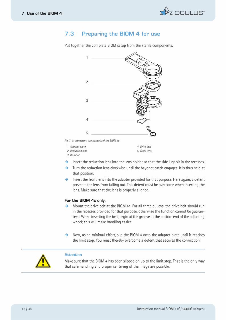
Put together the complete BIOM setup from the sterile components.
fig. 7-4: Necessary components of the BIOM 4c
Insert the reduction lens into the lens holder so that the side lugs sit in the recesses.
Turn the reduction lens clockwise until the bayonet catch engages. It is thus held atthat position.
Insert the front lens into the adapter provided for that purpose. Here again, a detentprevents the lens from falling out. This detent must be overcome when inserting thelens. Make sure that the lens is properly aligned.
For the BIOM 4c only:Mount the drive belt at the BIOM 4c. For all three pulleys, the drive belt should runin the recesses provided for that purpose, otherwise the function cannot be guaran-teed. When inserting the belt, begin at the groove at the bottom end of the adjustingwheel; this will make handling easier.
Now, using minimal effort, slip the BIOM 4 onto the adapter plate until it reachesthe limit stop. You must thereby overcome a detent that secures the connection.
Attention
Make sure that the BIOM 4 has been slipped on up to the limit stop. That is the only waythat safe handling and proper centering of the image are possible.
1 Adapter plate 4 Drive belt2 Reduction lens 5 Front lens3 BIOM 4c
1
2
3
4
5
12 / 34 Instruction manual BIOM 4 (G/54400/0109/en)

7 Use of the BIOM 4
7.3.1 Under sterile conditions: Perform a safety function test
Make sure that all components are present and are sterile.
Flip the BIOM against the adapter plate. It is equipped with a swivel mechanism for90° and a detent for this purpose.
Make sure that the housing body can be shifted without resistance.
fig. 7-5: Moving Components of the BIOM 4m
Check that the safety insertion for the lens holder runs smoothly by sliding it in andout several times by hand.
Check the function of the focusing wheel and shorten the overall length of the BIOMuntil the bridge is located at the top position.
Attention
If one of these functions is not assured, the unit may not be used.
Instruction manual BIOM 4 (G/54400/0109/en) 13 / 34

7 Use of the BIOM 4
7.3.2 Connect the BIOM 4 to the microscope
Slide the adapter plate with the BIOM components in compact state into the dovetailmount that is installed at the microscope. Secure the adapter into place with theknurled screw.
fig. 7-6: BIOM 4c secured in the dovetail mount
☞
Note: For BIOM 4c only
Also connect the control cable to one of the side couplers of the SDI 4c. Make sure thatthe cable does not touch any unsterile parts of the microscope.
Suggestion: If surgery is to be done on the left eye, connect the control cable at the lefthand side of the SDI. Or vice-versa if surgery is being done on the right eye.
For the BIOM 4c only: Installation of the cable duct
The cable duct helps to keep the connecting cable for the drive unit at the BIOM 4c (alsofits BIOM 3c) away from unsterile microscope parts.
The cable duct can be sterilized in a steam autoclave and is conditioned in the same wayas all other BIOM 4 components. Install the sterile cable duct at the plug and cable asshown in (fig. 7-7, page 15) and then connect the plug of the BIOM 4c with the socket onthe SDI 4c housing.
14 / 34 Instruction manual BIOM 4 (G/54400/0109/en)

7 Use of the BIOM 4
Fit the cable duct at the end of the plug (2) first.
Then fit the other semi-open part (1) over the cable.
Proceed in reverse order prior to conditioning.
fig. 7-7: Installation of the cable duct at the BIOM 4c
Caution:
The cable duct must be removed before conditioning, otherwise sterilization is not possible.
1
2
Instruction manual BIOM 4 (G/54400/0109/en) 15 / 34
7 Use of the BIOM 4
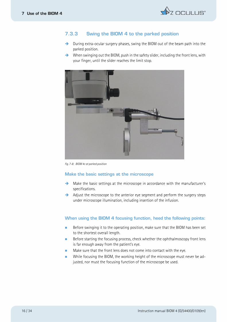
7.3.3 Swing the BIOM 4 to the parked position
During extra-ocular surgery phases, swing the BIOM out of the beam path into theparked position.
When swinging out the BIOM, push in the safety slider, including the front lens, withyour finger, until the slider reaches the limit stop.
fig. 7-8: BIOM 4c at parked position
Make the basic settings at the microscope
Make the basic settings at the microscope in accordance with the manufacturer’sspecifications.
Adjust the microscope to the anterior eye segment and perform the surgery stepsunder microscope illumination, including insertion of the infusion.
When using the BIOM 4 focusing function, heed the following points:
Before swinging it to the operating position, make sure that the BIOM has been setto the shortest overall length.
Before starting the focusing process, check whether the ophthalmoscopy front lensis far enough away from the patient’s eye.
Make sure that the front lens does not come into contact with the eye.
While focusing the BIOM, the working height of the microscope must never be ad-justed, nor must the focusing function of the microscope be used.
16 / 34 Instruction manual BIOM 4 (G/54400/0109/en)

7 Use of the BIOM 4
For BIOM 4c only (focusing done by electric motor):Only use the BIOM 4c’s motorized focusing function when the front lens is farenough away from the patient’s eye.
The surgeon may only use the motorized focusing function when the distance be-tween the ophthalmoscopy front lens and the eye is simultaneously monitored.
It must be ensured that the operator can stop the motorized focusing function atany time.
Attention
After the BIOM 4 has been swung in into the working position, the following must not beperformed during the proper use:
to use the rough adjustment mechanism of the microscope support under any circumstances (since the mechanism is not designed for precisely controlled movement).
to change the height position of the microscope support by mechanical or motorized means whilst above the operating area.
to change the patient´s position by raising/lowering the OP-table.
Visualization of the posterior eye segment
After all preparations for surgery in the posterior segment have been completed proceedas follows, without changing the microscope position!
Use a suitable endoillumination.
Swing the BIOM 4 into the beam path of the microscope. Lift up safety insertion andonly release it again when the swung-in end position has been reached.
The lens slides down to its designated position. This position has been reached whenthe control marks are fully visible.
Turn off the microscope illumination.
Activate the SDI to right the complete image reversal.
For BIOM 4c and SDI 4c only: If the BIOM 4c is swung out of the beam path the inverter function is not activated.
While swinging the BIOM 4c into working position the SDI 4c is activated automatically.
The position switch on board of the BIOM 4c thus operates the re-inverting function.
If another status of the inverter is desired, the SDI 4c can be optionally operated viaa combi foot switch.
At a low microscope magnification: Begin initial focusing of the BIOM 4-image byturning the BIOM 4 focus adjusting wheel.
Magnify the image section by actuating the focus foot switch at the microscope.
Instruction manual BIOM 4 (G/54400/0109/en) 17 / 34

7 Use of the BIOM 4
Then use the microscope footswitch control to zoom in to maximum magnification.Now finely focus the image with the adjusting knob of the BIOM 4. Only thus is a parfocal image (i.e. a sharp image at every magnification) guaranteed!
For the BIOM 4c only:
Adjust the sharpness of the image with the rocker of the combination foot switch,both for initial focusing and for parfocally setting the image.
The microscope magnification should then be reduced to the minimum required, inorder to achieve as wide a fundus view as possible.
The use of the focusing function with the microscope foot pedal when the BIOM 4is in use only changes the size of the image field ("keyhole effect").
Attention
During the whole process, make sure that the front lens cannot come into contact withthe cornea!
The cornea must be kept moist with a suitable fluid, to protect the cornea and to achievea good and clear view of the fundus.
Swing the BIOM 4 back to its parked position
After completing the surgery in the posterior segment, slide the safety insertion ofthe BIOM 4 upwards by hand and swing the BIOM aside.
Deactivate the SDI.
For BIOM 4c and SDI 4c only:
Swinging the BIOM 4c aside deactivates the SDI 4c.
18 / 34 Instruction manual BIOM 4 (G/54400/0109/en)

7 Use of the BIOM 4
Remove the BIOM 4 from the microscope
After completing the surgery, loosen the knurled screw and remove the BIOM 4, in-cluding the adapter plate, from the dovetail mount.
For the BIOM 4c only:
Also disconnect the plug of the BIOM 4c-drive unit from the coupler at the SDI 4chousing. Only pull on the corrugated sleeve of the plug (fig. 7-9, page 19). When theplug is pushed into the socket, the plug locks into place automatically. The lock canonly be released by pulling on the corrugated sleeve.
Note
Always grip the plug of the BIOM 4c at the sleeve, in order to release the lock. Pulling onthe cable itself could damage it and the complete drive module would then have to beexchanged.
fig. 7-9: Unlocking the BIOM 4c plug
Instruction manual BIOM 4 (G/54400/0109/en) 19 / 34
7 Use of the BIOM 4
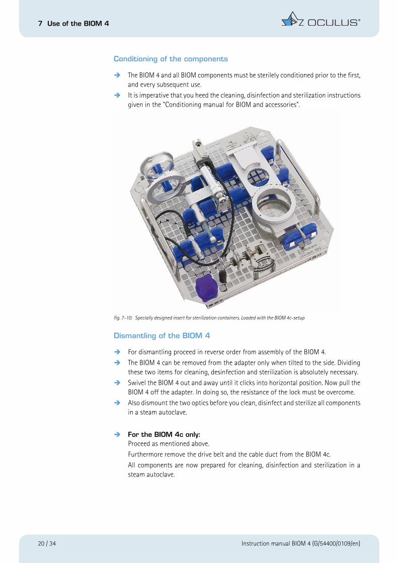
Conditioning of the components
The BIOM 4 and all BIOM components must be sterilely conditioned prior to the first,and every subsequent use.
It is imperative that you heed the cleaning, disinfection and sterilization instructionsgiven in the "Conditioning manual for BIOM and accessories".
fig. 7-10: Specially designed insert for sterilization containers. Loaded with the BIOM 4c-setup
Dismantling of the BIOM 4
For dismantling proceed in reverse order from assembly of the BIOM 4.
The BIOM 4 can be removed from the adapter only when tilted to the side. Dividingthese two items for cleaning, desinfection and sterilization is absolutely necessary.
Swivel the BIOM 4 out and away until it clicks into horizontal position. Now pull theBIOM 4 off the adapter. In doing so, the resistance of the lock must be overcome.
Also dismount the two optics before you clean, disinfect and sterilize all componentsin a steam autoclave.
For the BIOM 4c only:Proceed as mentioned above.
Furthermore remove the drive belt and the cable duct from the BIOM 4c.
All components are now prepared for cleaning, disinfection and sterilization in asteam autoclave.
20 / 34 Instruction manual BIOM 4 (G/54400/0109/en)
7 Use of the BIOM 4
7.4 Practical application tips for the BIOM 4
Attention
Take suitable measures to suppress uncontrolled head movements of the patient duringthe surgery. These could cause injury to the patient.
Any contact of the front lens with the cornea must be avoided in general.
If, however, the lens does happen to come into contact with the cornea, the image willimmediately become blurred. In an extreme emergency, e.g. an uncontrolled downwardmovement of the microscope, that cannot be stopped using the emergency stop switchon the microscope, pull or move the complete operating microscope upwards, or shift theBIOM 4 out of the beam path.
After a contact between front lens and the eye, swing the BIOM 4 out, or slide the safetyinsertion upwards to facilitate cleaning of the optics, so that you can clean the lens witha sterile swab.
Make sure that the cornea is sufficiently moistened with a suitable solution. This will pre-vent damage to the cornea and will give you the optimal view into the eye.
Using the focus of the microscope during use of the BIOM 4, creates a field aperture effect. The greater the distance between the eye and the microscope, the smaller the an-gle of observation. This leads to the so-called "keyhole effect".
Focusing on the BIOM 4 is done manually with the adjusting wheel and can also be doneby a sterile assistant, who follows the surgery via a co-observer viewer.
For the BIOM 4c only:
Focusing of the BIOM 4c is done solely by the surgeon by means of the combination footswitch while observing through the microscope.
Note
Adjust the ophthalmoscopy front lens rather upwards for hyperopic eyes and downwardsfor myopic eyes.
Instruction manual BIOM 4 (G/54400/0109/en) 21 / 34

8 Troubleshooting
8 Troubleshooting
Attention
If an error occurs which you are unable to correct by following the instructions below,label the device as "out of order" and contact our service department. (Address: sect. 12.3,page 28)
Troubleshooting guide - BIOM 4
Fault Possible Cause HelpThe safety extension of the BIOM 4 isstuck
BIOM 4 must not be used in this condition !
Deposits on the BIOM 4 due to inade-quate sterilization
Foreign body in safety rod extensionchannel
Careful mechanical cleaning, use of an-other sterilizing agent, use ultra sonicbath
Careful mechanical cleaning and removalof the foreign bodyCleaning the BIOM 4 in the ultrasonicbathTreat the slider with a suitable, siliconeoil-free lubricant prior to the next steril-ization
Adapter wobblesDovetail mount wobbles
The knurled head locking screws arelooseScrews are loose
Tighten the locking screws by hand
Tighten the screws with a suitable screw-driver
Image is cropped or out-of-center The SDI, other components, or theBIOM 4 adapter are incorrectly mountedat an angleThe front lens clip is bent or mechanicallydamaged
Correct the assembly
Carefully bend the front lens clip backinto shape or senr it to our service address for adjustment
Unclear image Soiled glass surfacesThe glass surfaces have been damagedduring sterilizationThe glass surfaces have been mechani-cally damagedThe ophthalmoscopy front lens is in contact with the eyeDry patient cornea
Clean the glass surfacesChange the sterilization method, replacelenses if necessaryGreater care in use and storage of lenses;replace if necessaryCorrect the working distance, clean thelens surfacesMoisten the cornea regularly with a suit-able solution
Unfocused image Incorrect adjustment of the BIOM 4
A reduction lens is not being usedThe reduction lens is not compatible withthe microscope objective
Focus the BIOM 4 in accordance with theinstructionsUse a reduction lensCheck the engraving on the reductionlens and exchange it, if necessary (referto "Optical Components, Pg. 29)
22 / 34 Instruction manual BIOM 4 (G/54400/0109/en)

8 Troubleshooting
only BIOM 4c
Fundus view is too narrow Too much distance between the ophthal-moscopy lens and the eyeMagnification of the microscope systemto high
Carefully reduce the distance using themicroscope fine adjustment mechanismReduce magnification of the microscope
The eye or the lens reflect strongly The microscope light is on Turn the light off, illuminate only in-traocular
The BIOM 4 cannot be detached from theadapter
BIOM 4 has not been tilted to the side fordisassemblyVacuum has developed between theBIOM 4 and the adapter, or there are de-posits on the connecting parts
Tilt the BIOM 4 to the side
Place the BIOM 4 and adapter into an ul-trasonic bath (for approx. 5 min)
No function whatsoever when the com-bination foot switch is actuated
The combination foot switch is not connected to the SDI 4cThe SDI 4c is not connected to the 6V-15V power supply
Power failure or power outlet is not ac-tive
The electric sockets on the support are in use but inactive
Establish the connection to the SDI 4c
Establish the connection to the 6V-15V power supply
Inform the in-house electrician
Use the 6V-15V plug transformerUse the mechanical adjusting element or adjusting wheelActivate the sockets in accordance with the instructions for the standAsk the microscope manufacturer for as-sistance
Malfunciton when using the combina-tion foot switch
5-pole plug has been forcibly plugged in the wrong way round
Plug it in the right way round (pay atten-tion to the lug and slot of the polarity re-versal protection)
Motorized focusing not possible with the BIOM 4c when using the combination control unit
BIOM 4c connector not plugged into the SDI 4c properlyDefective drive belt
Drive belt missingConnecting cable damagedDefective drive module
Plug in the connector correctly
Install a new sterile drive belt or focus manually using the focusing knob at the BIOM 4cInstall a sterile drive beltExchange the drive moduleExchange the drive module
Fault Possible Cause Help
Instruction manual BIOM 4 (G/54400/0109/en) 23 / 34
9 Exchanging the BIOM 4c Drive Module
9 Exchanging the BIOM 4c Drive Module
Attention
Handle the drive module and the clutch disk with care!
The drive module has a magnetic coupling. Strong magnetic forces!
Risk of injury!
Dismount the BIOM 4c from the microscope and remove the drive belt.
Remove only the one hexagon socket head screw (allen screw) M2.5 (key size 2),which holds the drive module in place on the triangular base plate.
Slightly move the drive unit from side to side while pulling it out of the position.
Clean the clutch disk of the magnetic clutch that is mounted on the base plate.
Install the new drive module.
To do so, insert the square shoulder of the drive module the correct way round intothe square recess in the triangular base plate.
Now fasten down the drive module with a new hexagon socket head screw.
Use only the supplied, self-locking hexagon socket head screw M2.5x4 (with blue ad-hesive coating).
Attention
Heed the assembly instructions provided with the drive module.
10 Care and Maintenance
Attention
Please heed the separate Conditioning manual.
Note
The sterilization insert from the company Oculus Optikgeaete GmbH (Art. No. 54185) canalso be used for cleaning the BIOM components in a washer.
24 / 34 Instruction manual BIOM 4 (G/54400/0109/en)

10 Care and Maintenance
General
Do not use aggressive cleaning agents that contain chlorine or solvents, nor abrasiveor sharp-edged cleaning products to clean the unit.
Always heed the product descriptions and directions for use of products you use todesinfect.
Due to the special surface finish required for sterilizability of the BIOM 4, structuralpatterns may become visible. This unavoidable minor blemish does not in any wayadversely affect the function, handling and sterilization of the unit.
Care of the BIOM 4
After cleaning and prior to sterilization, treat all moving parts of the BIOM 4 with asterilizable, silicone-oil-free conditioning lubricant.
Remove any excess oil from the surfaces, as staining could otherwise occur.
The following can be used for this purpose: Aesculap Sterilit i (JG600) oilspray orMedicon Instrumentensprühöl 46.00.40.
Cleaning and sterilizing the BIOM 4
Clean the BIOM 4 with water immediately after use. This prevents incrustationswhich can make sterilization impossible.
The BIOM 4 can be cleaned and disinfected in a dishwasher with a mildly alkalinedetergent, as well as in the disinfector (refer to the Conditioning manual).
All components of the BIOM 4 listed in Chapter 14 can be sterlized in a steam auto-clave (max. 134°C / 273°F). Always remove the optical system components beforeautoclaving.
Instruction manual BIOM 4 (G/54400/0109/en) 25 / 34

10 Care and Maintenance
Attention
Use only demineralized, filtered water for steam sterilization. Only in this way do you pro-tect the unit against deposits which can adversely affect its function.
Take care when sterilizing the BIOM 4 that the safety extension rod is completelypulled out. This permits a free flow of steam through the hollow spaces of the unit.
The Oculus Optikgeaete GmbH company offers a sterilization-container with a spe-cially designed inset keeping the BIOM 4, optical components and the adapter platein place for optimum care during and after sterilization.
Attention
Sterilization of the BIOM 4 using STERRAD® is not allowed. It may damage the BIOM 4.
Cleaning and sterilizing the adapter
Dismount the adapter plate from the BIOM 4, as this is the only way to ensure sat-isfactory cleaning and sterilization of this component and of the BIOM 4.
Clean the adapter by wiping it off with a damp cloth.
The adapter can be cleaned and disinfected in a dishwasher with a mildly alkalinedetergent, as well as in the disinfector (refer to the Reconditioning Manual).
All BIOM 4 adapters provided by us are autoclavable with steam (max. 134°C/273°F).
Attention
Sterilization of the BIOM 4 adapters using STERRAD® is not allowed. It may damage theadapters.
Cleaning and sterilizing the reduction lens and the ophthalmoscopy lens
Dismantle the optical components of the BIOM 4 before cleaning and sterilizing it.
Clean the optical system with water immediately after use. This avoids incrustationswhich can make complete sterilization more difficult.
The optics (lenses) can be cleaned and disinfected in a dishwasher with a mildly al-kaline detergent, as well as in the disinfector (refer to the conditioning manual).
Under no circumstances should the optical system be autoclaved while beingmounted on the BIOM 4. The presently available reduction lenses and front lenses,with the exception of disposable lenses sets, can be sterilized in a steam autoclaveat a max. temperature of 134°C / 273°F. To prevent water stains on the optics, thefront lenses and reduction lenses should be kept in a vertical position during steril-ization.
26 / 34 Instruction manual BIOM 4 (G/54400/0109/en)

11 Disposal of Used Devices
The optics can be double shrink-wrapped or secured in the sterilization inset fromOculus Optikgeaete GmbH, for sterilization in the autoclave.
Please be sure to heed the additional instructions given in the specific conditioningmanual that are provided with all sterilizable OCULUS products and sterilization anddisinfection systems.
Avoid damage to the surface and its coating. Always place the optical componentson a soft surface.
11 Disposal of Used Devices
In accordance with Directive 2002/96/EC of the European Parliament and the Council of 27 Janu-ary 2003, and in accordance with German law governing the circulation, return and environmen-tally friendly disposal of used electrical and electronic devices, such appliances must be recycledand may not be discarded as household waste.
12 Warranty and Service
12.1 Warranty
The device you have purchased is a high-quality OCULUS product. This device was care-fully manufactured using quality materials and modern production methods. Any soft-ware included in the delivery was tested by us and complies with technical standards.Prior to and while operating the device it is important that you observe the instructionmanual and safety instructions.
The device carries a warranty to which you are entitled in accordance with the legal provisions.
If the unit is tampered in any way by non-authorized persons, all warranty claims are ren-dered null and void, because improper modifications, maintenance and repairs can leadto considerable hazards for the user and the patient.
In the event of transport damage, we request that you notify the shipping company im-mediately and have the damage confirmed on the consignment note, to enable a properclaims settlement procedure.
Overall, the general terms and conditions of business and delivery apply as per the dateof purchase.
12.2 Assumption of liability for functions and damage
Oculus Optikgeaete GmbH will only accept responsibility for the safety, reliability and ser-viceability of the unit if the BIOM 4 is used in compliance with the instructions containedin this instruction manual.
Instruction manual BIOM 4 (G/54400/0109/en) 27 / 34

13 Declaration of Conformity
OCULUS shall not assume any liability if assembly, extensions, adjustments, changes orrepairs are carried out by unauthorised personnel, if the unit is maintained improperly orif it is handled incorrectly.
12.3 Manufacturer’s and service addresses
Our service department or authorised representatives will furnish you with additional in-formation.
Manufacturer - Service Addresses:
Germany:OCULUS Optikgeräte GmbH
Münchholzhaeuser Str. 29
D - 35582 Wetzlar, Germany
Tel.: ++49 641/2005-0
Fax: ++49 641/2005-295
E-mail: [email protected]
13 Declaration of Conformity
We declare under our sole responsibility that this product meets the fundamental re-quirements of Annex 1 of Directive 93/42/EEC of 14th June, 1993 for medical products.
Following harmonized standards were employed to verify the above mentioned require-ments:
-DIN EN ISO 15004
according to the regulations of MDD
Dipl.Ing. Rainer Kirchhübel
ManagementOCULUS Optikgeräte GmbH
28 / 34 Instruction manual BIOM 4 (G/54400/0109/en)

14 Order Information, Accessories and Replacement Parts
14 Order Information, Accessories and Replacement Parts
Basic unit
Accessories for the BIOM 4c / BIOM 4cl
Component Order number
BIOM 4c 54400
BIOM 4cl 54403
BIOM 4m 54462
BIOM 4ml 54463
Component Order number
Drive belts (pack of 10) 54176
Cable duct (pack of 5) 54178
Instruction manual BIOM 4 (G/54400/0109/en) 29 / 34

14 Order Information, Accessories and Replacement Parts
Adaption components for BIOM 4
Sterilization components for BIOM 4
Component Order number
Adapter for Zeiss Retrolux 1/3 54421
Adapter for Zeiss Retroskop 1/2 54422
Adapter for Zeiss OPMI MDI/MDO/MDU/Retrolux CS/VISU/Lumera 54423
Adapter for Zeiss OPMI 6 54424
Adapter for Zeiss Retroskop CS 54428
Adapter for Takagi OM 18 54418
Adapter for Moeller/WedelOphtamic 900/Hi-R 900 54440
Adapter OPMI VISU with VISULUX slitlamp 54431
Adapter for Topcon OMS 600/OMS 610/ OMS 650/ OMS 800 Pro/OMS 800Standard/OMS 710
54441
Adapter for Topcon OMS 110 54442
Adapter for Leica M690 with 0°-Coobserver 54444
Adapter for Leica M500/M501/M620 54445
Adapter for Leica M690 54446
Adapter for Leica M841/M820/M844 54448
Dovetail for Zeiss OPMI VISU/Lumera 54511
Distancing part for ring support objective at Zeiss OPMI 6 54535
Adaption part for 0°-Coobservation holder at Zeiss OPMI 6 54536
Dovetail for Zeiss OPMI 1/6 54537
Dovetail for Zeiss MDO/Retrolux CS 54538
Distancing part Zeiss OPMI MD 54539
Distancing part for Möller Ophtamic 900 mit 20°-illumination unit 54639
Component Order number
Sterilization-Container with inset for BIOM 4 and accessories 54180
Inset for steri-container 54185
Paper filters for steri-container (1000 pcs/box) 54190
Seals for steri-container (1000 pcs/box) 54194
Indicator labels for steri-container (1000 pcs/box) 54193
Autoclavable adhesive tape with steam indicator, 50 m long, 19 mm wide 54192
30 / 34 Instruction manual BIOM 4 (G/54400/0109/en)

14 Order Information, Accessories and Replacement Parts
Optical components for BIOM 4
Reduction lenses
Ophthalmoscopy front lenses
Disposable lens set
Component Order number
Reduction lens for f = 175 mm 54547
Reduction lens for f = 200 mm 54545
Reduction lens for f = 225 mm 54548
Reduction lens for Retroskop 54544
Component Order number
Autoclavable lenses:
Wide-Field-lens, Diameter 12 mm for BIOM 4 53601
Wide-Field-(Enhanced)-lens for BIOM 4 53602
90 D-lens for BIOM 4 53604
Hi Res-lens for BIOM 4 53606
Wide field lens set, including reduction lens for objective focal lengths off=175 and f= 200mm (disposable, pack of 6), not to be used with BIOM longversion
53595
Instruction manual BIOM 4 (G/54400/0109/en) 31 / 34
15 Technical Data
Image Inverting Systems for BIOM 4
15 Technical Data
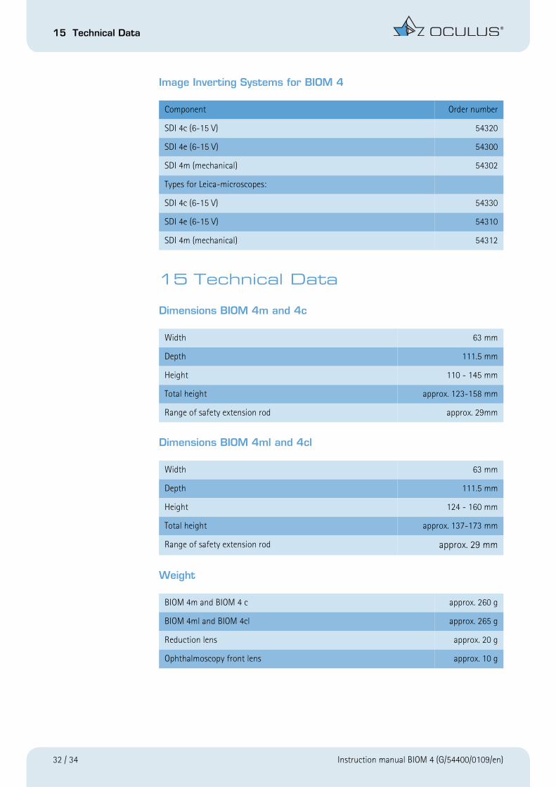
Dimensions BIOM 4m and 4c
Dimensions BIOM 4ml and 4cl
Weight
Component Order number
SDI 4c (6-15 V) 54320
SDI 4e (6-15 V) 54300
SDI 4m (mechanical) 54302
Types for Leica-microscopes:
SDI 4c (6-15 V) 54330
SDI 4e (6-15 V) 54310
SDI 4m (mechanical) 54312
Width 63 mm
Depth 111.5 mm
Height 110 - 145 mm
Total height approx. 123-158 mm
Range of safety extension rod approx. 29mm
Width 63 mm
Depth 111.5 mm
Height 124 - 160 mm
Total height approx. 137-173 mm
Range of safety extension rod approx. 29 mm
BIOM 4m and BIOM 4 c approx. 260 g
BIOM 4ml and BIOM 4cl approx. 265 g
Reduction lens approx. 20 g
Ophthalmoscopy front lens approx. 10 g
32 / 34 Instruction manual BIOM 4 (G/54400/0109/en)

15 Technical Data
Operating conditions with optical system
Sterilization and disinfection procedures
Symbols on the instrument
The instruments meets the requirements of the specified standard:
Follow the instruction manual:
Type B application:
Type of device protection:
IP 64
Temperature +10 °C (50° F) to+40 °C (104^F)
Humidity 30% to 70%
Air pressure 700 hPa to 1060 hPa
BIOM 4 steam autoclaving,max. 134°C (273° F)
Reduction lens (only the reduction lenses listed in this manual) steam autoclaving,max. 134°C (273° F)
Ophthalmoscopy front lens (only the lenses listed in this manual) steam autoclaving,max. 134°C (273° F)
Adapter steam autoclaving,max. 134°C (273° F)
Drive belt steam autoclaving,max. 134°C (273° F)
Instruction manual BIOM 4 (G/54400/0109/en) 33 / 34

15 Technical Data
The unit can be attached to the following microscopes:
Zeiss:
OPMI 1/6
OPMI CS with Retrolux 1/3/CS
OPMI CS withRetroskop 1/2/CS
OPMI MDI/MDO/MDU
OPMI VISU 150/ VISU 160
OPMI VISU 200 / VISU 210
OPMI Lumera
OPMI Lumera T
Leica:
M500 / M501 / M620
M650 / M690
M820 / M840 / M841 / M844
Moeller:
Ophtamic 900 / Hi-R 900 / EOS 900
Takagi:
OM 18
Topcon:
OMS 600 / OMS 610 / OMS 650
OMS 110
OMS 710
OMS 800 Standard / OMS 800 Pro
Kaps:
SOM
34 / 34 Instruction manual BIOM 4 (G/54400/0109/en)

Disposable B
IOM
Wide Field Lens-Set for f=175m
m and for f=200m
m
Order no.: 53595
Instructions for use D
escription: Disposable lenses for use w
ith the BIO
M 4 m
odel wide-angle view
ing system
from O
culus. Parts include: (1x) D
isposable wide-field lens,
(1x) D
isposable reduction lens for use with an f=175 m
m or
f=200 mm
objective lens. W
arning: Never use a product that appears to be dam
aged! D
irections: N
on- Sterile personnel
1. C
heck the packaging for damage. The product m
ust not be used if any damage is found on the packaging.
2. A
fter a visual check, open the outer plastic wrapping w
ithout touching the inner fleece packing of the lenses. 3.
Let the lenses, which are packed in sterile fleece, slide on to a sterile surface. M
ake sure that the sterile lenses are not contaminated
during this process. Sterile O
perating Nurse/Surgtech
4.
Rem
ove the lenses from the fleece packing w
ithout touching the lens surface. 5.
Hold the reduction lens (A
) by its black plastic ring and place it in the Biom
´s lens holder (B) so that the m
ounting ring tabs on the lens fit into the notches in the lens holder.
6. Turn the reduction lens clockw
ise, passing through the resistance of the spring clip. The reduction lens is now secure and w
ill not fall out. 7.
Using your thum
b and index finger, hold the wide-field lens (D
) on either side of the black arm w
ithout touching the lens surface. (Figure 1) Failure to hold the clip in this regard m
ay result in the premature breaking of the clip. The lens is correctly orientated if its position m
atches the diagram
below. (Figure 2) Fasten the lens by inserting the black plastic tab into the slot (C
) of the Biom
lens holder passing the resistance until the sm
all outer tabs click and lock into position. 8.
To remove the lenses after use, grasp the w
ide-field lens clip in the “front” (Figure 3) and simply break the lens clip in a firm
downw
ard motion.
Next, rem
ove the “back” portion clip and discard. Turn the reduction lens counter clockwise and carefully lift out of the lens ring holder.
Sterilization: These lenses are delivered in a sterile condition and are intended for SIN
GLE U
SE ON
LY . After surgery they should be properly disposed of according
to contaminated m
edical waste guidelines of your facility.
If sterile packaging appears damaged, do not use this item
.