
Instruction Manual for Portable Compressors English XA(S ... · Instruction Manual for Portable...
75
Instruction Manual for Portable Compressors English XAS 127 Kd - XAS 275 KD7 XA(S) 137 Kd - XA(S) 300 KD7 Engine XA(S) 137 KdG - XA(S) 300 KD7G Kubota V3800 XAHS 107 Kd - XAHS 225 KD7
Transcript of Instruction Manual for Portable Compressors English XA(S ... · Instruction Manual for Portable...

Instruction Manualfor Portable CompressorsEnglish
XAS 127 Kd - XAS 275 KD7XA(S) 137 Kd - XA(S) 300 KD7 EngineXA(S) 137 KdG - XA(S) 300 KD7G Kubota V3800XAHS 107 Kd - XAHS 225 KD7

08/2011
Instruction Manualfor Portable Compressors
XAS 127 Kd - XAS 275 KD7XA(S) 137 Kd - XA(S) 300 KD7XA(S) 137 KdG - XA(S) 300 KD7GXAHS 107 Kd - XAHS 225 KD7
Printed matter N°2954 3170 04
Original instructions

78 9 9123
4
4
68899..
256
77789
4.1.4 Lifting instructions................................. 294.2 Control panel.............................................. 304.3 Starting/Stopping ....................................... 304.3.1 Before starting ....................................... 304.3.2 Starting procedure.................................. 314.3.3 During operation .................................... 324.3.4 Stopping procedure ................................ 324.3.5 Generator function (XA(S) 137 KdG -
XA(S) 300 KD7G) 33
5 Maintenance ............................................. 345.1 Use of service paks .................................... 345.2 Preventive maintenance schedule .............. 345.3 Maintenance schedule compressor............. 345.4 Fuel............................................................. 385.5 Lubrication oils .......................................... 385.6 Oil level check ........................................... 405.6.1 Check engine oil level ........................... 405.6.2 Check compressor oil level.................... 405.7 Oil and oil filter change ............................. 415.7.1 Engine oil and oil filter change.............. 415.7.2 Compressor oil and oil filter change...... 415.8 Compressor Oil Flushing Procedure .......... 425.9 Cleaning coolers......................................... 435.10 Battery care ................................................ 445.10.1 Electrolyte.............................................. 445.10.2 Activating a dry-charged battery ........... 445.10.3 Recharging a battery .............................. 445.10.4 Battery maintenance .............................. 445.11 Storage ....................................................... 455.12 Service paks ............................................... 455.13 Service kits................................................. 455.14 Compressor element overhaul.................... 45
- 5 -
PrefacePlease read the following instructions carefullybefore starting to use your compressor.It is a solid, safe and reliable machine, builtaccording to the latest technology. Follow theinstructions in this booklet and we guarantee youyears of troublefree operation.Always keep the manual available near the machine.In all correspondence always mention thecompressor type and serial number, shown on thedata plate.The company reserves the right to make changeswithout prior notice.
Table of contents1 Safety precautions for portable
compressors with generator 71.1 Introduction ..................................................1.2 General safety precautions ........................... 1.3 Safety during transport and installation .......1.4 Safety during use and operation...................1.5 Safety during maintenance and repair........ 11.6 Tool applications safety ............................. 11.7 Specific safety precautions......................... 1
2 Leading particulars .................................. 12.1 Description of safety pictograms used in this
manual 142.2 General description .................................... 1
3 Main Parts................................................. 13.1 Compressor regulating system ................... 13.1.1 Overview (Load condition)................... 13.1.2 Air flow.................................................. 13.1.3 Oil system .............................................. 13.1.4 Continuous pneumatic regulating system .
203.2 Electrical system ........................................ 23.2.1 Description............................................. 23.3 Markings and information labels ............... 2
4 Operating instructions ............................. 24.1 Parking, towing and lifting instructions ..... 24.1.1 Parking instructions ............................... 24.1.2 Towing instructions ............................... 24.1.3 Height adjustment .................................. 2
.
45813
4
555
6
- 6 -
5.15 Liability ...................................................... 45
6 Adjustments and servicing procedures .. 466.1 Adjustment of the continuous pneumatic
regulating system 466.2 Air filter engine/compressor....................... 486.2.1 Servicing ................................................ 486.2.2 Main parts .............................................. 486.2.3 Cleaning the dust trap ............................ 486.2.4 Cleaning instructions filter element ....... 486.2.5 Replacing the air filter element .............. 496.3 Air receiver................................................. 506.4 Safety valve ................................................ 506.5 Fuel system................................................. 506.6 Brake (= option) adjustment....................... 516.7 Brake shoe adjustment................................ 516.7.1 Brake cable adjustment .......................... 526.7.2 Brake adjustment check ......................... 526.8 Wheels ........................................................ 536.8.1 Wheel check ........................................... 536.8.2 Lubrication ............................................. 536.8.3 Wheel bolts check .................................. 546.8.4 Wheel bearing adjustment...................... 556.9 Towbar and overrun brake check ............... 566.9.1 Towbar and overrun brake lubrication... 57
7 Problem solving ........................................ 59
8 Available options ...................................... 62
9 Technical specifications ........................... 639.1 Torque values ............................................. 639.1.1 For general applications ......................... 639.1.2 For important assemblies ....................... 63
9.2 Compressor/Engine/Generator specifications64
9.2.1 Reference conditions.............................. 69.2.2 Limitations ............................................. 69.2.3 Performance data ................................... 69.2.4 Design data............................................. 79.2.5 Design data for generator....................... 7
10 Data plate .................................................. 7
11 Disposal ..................................................... 711.1 General ....................................................... 711.2 Disposal of materials.................................. 7
12 Maintenance Log ...................................... 7

nerator
tr
ee
italdisyn
ealyse
rrs
oo
Take necessary steps to keep unauthorized personsaway from the unit and eliminate all possible sourcesof danger at the unit.When handling, operating, overhauling and/orperforming maintenance or repair on Atlas Copcoequipment, the mechanics are expected to use safeengineering practices and to observe all relevant localsafety requirements and ordinances. The followinglist is a reminder of special safety directives andprecautions mainly applicable to Atlas Copcoequipment.These safety precautions apply to machineryprocessing or consuming air. Processing of any othergas requires additional safety precautions typical tothe application and are not included herein.Neglecting the safety precautions may endangerpeople as well as environment and machinery:- endanger people due to electrical, mechanical or
chemical influences,- endanger the environment due to leakage of oil,
solvents or other substances,- endanger the machinery due to function failures.All responsibility for any damage or injury resultingfrom neglecting these precautions or by non-observance of ordinary caution and due care requiredin handling, operating, maintenance or repair, also ifnot expressly mentioned in this instruction manual, isdisclaimed by Atlas Copco.
g
- 7 -
Safety precautions for portable compressors with ge
INTRODUCTION
The policy of Atlas Copco is to provide the users oftheir equipment with safe, reliable and efficientproducts. Factors taken into account are amongothers:- the intended and predictable future use of the
products, and the environments in which they areexpected to operate,
- applicable rules, codes and regulations,- the expected useful product life, assuming proper
service and maintenance,- providing the manual with up-to-date
information.Before handling any product, take time to read therelevant instruction manual. Besides giving detailedoperating instructions, it also gives specificinformation about safety, preventive maintenance,etc.Keep the manual always at the unit location, easyaccessible to the operating personnel.See also the safety precautions of the engine andpossible other equipment, which are separately sentalong or are mentioned on the equipment or parts ofthe unit.These safety precautions are general and somestatements will therefore not always apply to aparticular unit.Only people that have the right skills should beallowed to operate, adjust, perform maintenance orrepair on Atlas Copco equipment.
It is the responsibility of management to appoinoperators with the appropriate training and skill foeach category of job.Skill level 1: OperatorAn operator is trained in all aspects of operating thunit with the push-buttons, and is trained to know thsafety aspects.Skill level 2: Mechanical technicianA mechanical technician is trained to operate the unthe same as the operator. In addition, the mechanictechnician is also trained to perform maintenance anrepair, as described in the instruction manual, and allowed to change settings of the control and safetsystem. A mechanical technician does not work olive electrical components.Skill level 3: Electrical technicianAn electrical technician is trained and has the samqualifications as both the operator and the mechanictechnician. In addition, the electrical technician macarry out electrical repairs within the variouenclosures of the unit. This includes work on livelectrical components.Skill level 4: Specialist from the manufactureThis is a skilled specialist sent by the manufacturer oits agent to perform complex repairs or modificationto the equipment.In general it is recommended that not more than twpeople operate the unit, more operators could lead tunsafe operating conditions.
To be read attentively and acted accordingly before towing, lifting, operating, performinmaintenance or repairing the unit.

s,
de,
n,r
e,r
y.
eyf
ys,re
dllle
ealge
e
13 In the event the safety labels are damaged ordestroyed, they must be replaced to ensureoperator safety.
14 Keep the work area neet. Lack of order willincrease the risk of accidents.
15 When working on the unit, wear safety clothing.Depending on the kind of activities these are:safety glasses, ear protection, safety helmet(including visor), safety gloves, protectiveclothing, safety shoes. Do not wear the hair longand loose (protect long hair with a hairnet), orwear loose clothing or jewelry.
16 Take precautions against fire. Handle fuel, oil andanti-freeze with care because they areinflammable substances. Do not smoke orapproach with naked flame when handling suchsubstances. Keep a fire-extinguisher in thevicinity.
17 Portable compressors with generator (withearthing pin):Earth the generator as well as the load properly.
18 Portable compressors with generator IT:Note: This generator is built to supply a sheeralternating current IT network.Earth the load properly.
- 8 -
The manufacturer does not accept any liability for anydamage arising from the use of non-original parts andfor modifications, additions or conversions madewithout the manufacturer’s approval in writing.If any statement in this manual does not comply withlocal legislation, the stricter of the two shall beapplied.Statements in these safety precautions should not beinterpreted as suggestions, recommendations orinducements that it should be used in violation of anyapplicable laws or regulations.
GENERAL SAFETY PRECAUTIONS
1 The owner is responsible for maintaining the unitin a safe operating condition. Unit parts andaccessories must be replaced if missing orunsuitable for safe operation.
2 The supervisor, or the responsible person, shall atall times make sure that all instructions regardingmachinery and equipment operation andmaintenance are strictly followed and that themachines with all accessories and safety devices,as well as the consuming devices, are in goodrepair, free of abnormal wear or abuse, and arenot tampered with.
3 Whenever there is an indication or any suspicionthat an internal part of a machine is overheated,the machine shall be stopped but no inspectioncovers shall be opened before sufficient coolingtime has elapsed; this to avoid the risk ofspontaneous ignition of oil vapour when air isadmitted.
4 Normal ratings (pressures, temperatures, speedetc.) shall be durably marked.
5 Operate the unit only for the intended purpose anwithin its rated limits (pressure, temperaturspeeds, etc.).
6 The machinery and equipment shall be kept cleai.e. as free as possible from oil, dust or othedeposits.
7 To prevent an increase in working temperaturinspect and clean heat transfer surfaces (coolefins, intercoolers, water jackets, etc.) regularlSee the Preventive maintenance schedule.
8 All regulating and safety devices shall bmaintained with due care to ensure that thefunction properly. They may not be put out oaction.
9 Care shall be taken to avoid damage to safetvalves and other pressure-relief deviceespecially to avoid plugging by paint, oil coke odirt accumulation, which could interfere with thfunctioning of the device.
10 Pressure and temperature gauges shall be checkeregularly with regard to their accuracy. They shabe replaced whenever outside acceptabtolerances.
11 Safety devices shall be tested as described in thmaintenance schedule of the instruction manuto determine that they are in good operatincondition. See the Preventive maintenancschedule.
12 Mind the markings and information labels on thunit.

lee
g
e
e
ygyedd
y,y
eiren
gsad
etnot
11 Locate the unit away from walls. Take allprecautions to ensure that hot air exhausted fromthe engine and driven machine cooling systemscannot be recirculated. If such hot air is taken inby the engine or driven machine cooling fan, thismay cause overheating of the unit; if taken in forcombustion, the engine power will be reduced.
12 The electrical connections shall correspond tolocal codes. The machines shall be earthed andprotected against short circuits by fuses or circuitbreakers.
13 Never connect the generator outlets to aninstallation which is also connected to a publicmains.
14 Before connecting a load, switch off thecorresponding circuit breaker, and check whetherfrequency, voltage, current and power factorcomply with the ratings of the generator.
SAFETY DURING USE AND OPERATION
1 When the unit has to operate in a fire-hazardousenvironment, each engine exhaust has to beprovided with a spark arrestor to trap incendiarysparks.
2 The exhaust contains carbon monoxide which is alethal gas. When the unit is used in a confinedspace, conduct the engine exhaust to the outsideatmosphere by a pipe of sufficient diameter; dothis in such a way that no extra back pressure iscreated for the engine. If necessary, install anextractor. Observe any existing local regulations.Make sure that the unit has sufficient air intakefor operation. If necessary, install extra air intakeducts.
- 9 -
SAFETY DURING TRANSPORT AND INSTALLATION
To lift a unit, all loose or pivoting parts, e.g. doors andtowbar, shall first be securely fastened.Do not attach cables, chains or ropes directly to thelifting eye; apply a crane hook or lifting shacklemeeting local safety regulations. Never allow sharpbends in lifting cables, chains or ropes.Helicopter lifting is not allowed. It is strictly forbidden to dwell or stay in the risk zoneunder a lifted load. Never lift the unit over people orresidential areas. Lifting acceleration and retardationshall be kept within safe limits.1 Before towing the unit:
- ascertain that the pressure vessel(s) is (are)depressurized,
- check the towbar, the brake system and thetowing eye. Also check the coupling of thetowing vehicle,
- check the towing and brake capability of thetowing vehicle,
- check that the towbar, jockey wheel or standleg is safely locked in the raised position,
- ascertain that the towing eye can swivel freelyon the hook,
- check that the wheels are secure and that thetyres are in good condition and inflatedcorrectly,
- connect the signalisation cable, check all lightsand connect the pneumatic brake couplers,
- attach the safety break-away cable or safetychain to the towing vehicle,
- remove wheel chocks, if applied, anddisengage the parking brake.
2 To tow a unit use a towing vehicle of ampcapacity. Refer to the documentation of thtowing vehicle.
3 If the unit is to be backed up by the towinvehicle, disengage the overrun brake mechanism(if it is not an automatic mechanism).
4 Never exceed the maximum towing speed of thunit (mind the local regulations).
5 Place the unit on level ground and apply thparking brake before disconnecting the unit fromthe towing vehicle. Unclip the safety break-awacable or safety chain. If the unit has no parkinbrake or jockey wheel, immobilize the unit bplacing chocks in front of and/or behind thwheels. When the towbar can be positionevertically, the locking device must be applied ankept in good order.
6 To lift heavy parts, a hoist of ample capacittested and approved according to local safetregulations, shall be used.
7 Lifting hooks, eyes, shackles, etc., shall never bbent and shall only have stress in line with thedesign load axis. The capacity of a lifting devicdiminishes when the lifting force is applied at aangle to its load axis.
8 For maximum safety and efficiency of the liftinapparatus all lifting members shall be applied anear to perpendicular as possible. If required, lifting beam shall be applied between hoist anload.
9 Never leave a load hanging on a hoist.10 A hoist has to be installed in such a way that th
object will be lifted perpendicular. If that is nopossible, the necessary precautions must be taketo prevent load-swinging, e.g. by using twhoists, each at approximately the same angle noexceeding 30° from the vertical.

keir/
eet
rs
snire
icollr
tesrt
s
lleood,
ege
When the sound pressure level, at any pointwhere personnel normally has to attend, is:- below 70 dB(A): no action needs to be taken,- above 70 dB(A): noise-protective devices
should be provided for people continuouslybeing present in the room,
- below 85 dB(A): no action needs to be takenfor occasional visitors staying a limited timeonly,
- above 85 dB(A): room to be classified as anoise-hazardous area and an obvious warningshall be placed permanently at each entranceto alert people entering the room, for evenrelatively short times, about the need to wearear protectors,
- above 95 dB(A): the warning(s) at theentrance(s) shall be completed with therecommendation that also occasional visitorsshall wear ear protectors,
- above 105 dB(A): special ear protectors thatare adequate for this noise level and thespectral composition of the noise shall beprovided and a special warning to that effectshall be placed at each entrance.
18 Insulation or safety guards of parts thetemperature of which can be in excess of 80 °C(175 °F) and which may be accidentally touchedby personnel shall not be removed before theparts have cooled to room temperature.
19 Never operate the unit in surroundings wherethere is a possibility of taking in flammable ortoxic fumes.
20 If the working process produces fumes, dust orvibration hazards, etc., take the necessary steps toeliminate the risk of personnel injury.
- 10 -
3 When operating in a dust-laden atmosphere, placethe unit so that dust is not carried towards it by thewind. Operation in clean surroundingsconsiderably extends the intervals for cleaningthe air intake filters and the cores of the coolers.
4 Close the compressor air outlet valve beforeconnecting or disconnecting a hose. Ascertainthat a hose is fully depressurized beforedisconnecting it. Before blowing compressed airthrough a hose or air line, ensure that the open endis held securely, so that it cannot whip and causeinjury.
5 The air line end connected to the outlet valvemust be safeguarded with a safety cable, attachednext to the valve.
6 No external force may be exerted on the air outletvalves, e.g. by pulling on hoses or by installingauxiliary equipment directly to a valve, e.g. awater separator, a lubricator, etc. Do not step onthe air outlet valves.
7 Never move a unit when external lines or hosesare connected to the outlet valves, to avoiddamage to valves, manifold and hoses.
8 Do not use compressed air from any type ofcompressor, without taking extra measures, forbreathing purposes as this may result in injury ordeath. For breathing air quality, the compressedair must be adequately purified according to locallegislation and standards. Breathing air mustalways be supplied at stable, suitable pressure.
9 Distribution pipework and air hoses must be ofcorrect diameter and suitable for the workingpressure. Never use frayed, damaged ordeteriorated hoses. Replace hoses and flexiblesbefore the lifetime expires. Use only the correcttype and size of hose end fittings and connections.
10 If the compressor is to be used for sand-blastingor will be connected to a common compressed-air
system, fit an appropriate non-return valve (checvalve) between compressor outlet and thconnected sand-blasting or compressed-asystem. Observe the right mounting positiondirection.
11 Before removing the oil filler plug, ensure that thpressure is released by opening an air outlvalve.
12 Never remove a filler cap of the cooling watesystem of a hot engine. Wait until the engine hasufficiently cooled down.
13 Never refill fuel while the unit is running, unlesotherwise stated in the Atlas Copco InstructioBook. Keep fuel away from hot parts such as aoutlet pipes or the engine exhaust. Do not smokwhen fuelling. When fuelling from an automatpump, an earthing cable should be connected tthe unit to discharge static electricity. Never spinor leave oil, fuel, coolant or cleansing agent in oaround the unit.
14 All doors shall be shut during operation so as noto disturb the cooling air flow inside thbodywork and/or render the silencing leseffective. A door should be kept open for a shoperiod only e.g. for inspection or adjustment.
15 Periodically carry out maintenance workaccording to the maintenance schedule.
16 Stationary housing guards are provided on arotating or reciprocating parts not otherwisprotected and which may be hazardous tpersonnel. Machinery shall never be put intoperation, when such guards have been removebefore the guards are securely reinstalled.
17 Noise, even at reasonable levels, can causirritation and disturbance which, over a lonperiod of time, may cause severe injuries to thnervous system of human beings.

s,n
n
g.e
e.
dsdd,eeey
isde
sley
lsreeyr
g
SAFETY DURING MAINTENANCE AND REPAIR
Maintenance, overhaul and repair work shall only becarried out by adequately trained personnel; ifrequired, under supervision of someone qualified forthe job.1 Use only the correct tools for maintenance and
repair work, and only tools which are in goodcondition.
2 Parts shall only be replaced by genuine AtlasCopco replacement parts.
3 All maintenance work, other than routineattention, shall only be undertaken when the unitis stopped. Steps shall be taken to preventinadvertent starting. In addition, a warning signbearing a legend such as ”work in progress; donot start” shall be attached to the startingequipment. On engine-driven units the battery shall bedisconnected and removed or the terminalscovered by insulating caps. On electrically driven units the main switch shallbe locked in open position and the fuses shall betaken out. A warning sign bearing a legend suchas ”work in progress; do not supply voltage” shallbe attached to the fuse box or main switch.
4 Before dismantling any pressurized component,the compressor or equipment shall be effectivelyisolated from all sources of pressure and the entiresystem shall be relieved of pressure. Do not relyon non-return valves (check valves) to isolatepressure systems. In addition, a warning signbearing a legend such as ”work in progress; donot open” shall be attached to each of the outletvalves.
5 Prior to stripping an engine or other machine orundertaking major overhaul on it, prevent allmovable parts from rolling over or moving.
- 11 -
21 When using compressed air or inert gas to cleandown equipment, do so with caution and use theappropriate protection, at least safety glasses, forthe operator as well as for any bystander. Do notapply compressed air or inert gas to your skin ordirect an air or gas stream at people. Never use itto clean dirt from your clothes.
22 When washing parts in or with a cleaning solvent,provide the required ventilation and useappropriate protection such as a breathing filter,safety glasses, rubber apron and gloves, etc.
23 Safety shoes should be compulsory in anyworkshop and if there is a risk, however small, offalling objects, wearing of a safety helmet shouldbe included.
24 If there is a risk of inhaling hazardous gases,fumes or dust, the respiratory organs must beprotected and depending on the nature of thehazard, so must the eyes and skin.
25 Remember that where there is visible dust, thefiner, invisible particles will almost certainly bepresent too; but the fact that no dust can be seenis not a reliable indication that dangerous,invisible dust is not present in the air.
26 Never operate the unit at pressures or speedsbelow or in excess of its limits as indicated in thetechnical specifications.
27 Never operate the generator in excess of its limitsas indicated in the technical specifications andavoid long no-load sequences.
28 Never operate the generator in a humidatmosphere. Excessive moisture causesworsening of the generator insulation.
29 Do not open electrical cabinets, cubicles or otherequipment while voltage is supplied. If suchcannot be avoided, e.g. for measurements, tests oradjustments, have the action carried out by a
qualified electrician only, with appropriate tooland ascertain that the required bodily protectioagainst electrical hazards is applied.
30 Never touch the power terminals during operatioof the machine.
31 Whenever an abnormal condition arises, e.excessive vibration, noise, odour, etc., switch thcircuit breakers to OFF and stop the enginCorrect the faulty condition before restarting.
32 Check the electric cables regularly. Damagecables and insufficient lightening of connectionmay cause electric shocks. Whenever damagewires or dangerous conditions are observeswitch the circuit breakers to OFF and stop thengine. Replace the damaged wires or correct thdangerous condition before restarting. Make surthat all electric connections are secureltightened.
33 Avoid overloading the generator. The generator provided with circuit breakers for overloaprotection. When a breaker has tripped, reducthe concerned load before restarting.
34 If the generator is used as stand-by for the mainsupply, it must not be operated without controsystem which automatically disconnects thgenerator from the mains when the mains supplis restored.
35 Never remove the cover of the output terminaduring operation. Before connecting odisconnecting wires, switch off the load and thcircuit breakers, stop the machine and make surthat the machine cannot be started inadvertentlor there is any residual voltage on the powecircuit.
36 Running the generator at low load for lonperiods will reduce the lifetime of the engine.
r,o-
t,g-
r
err
alknyhn
dy.e
kde
rf
is
sy
23 Before clearing the unit for use after maintenanceor overhaul, check that operating pressures,temperatures and speeds are correct and that thecontrol and shutdown devices function correctly.
TOOL APPLICATIONS SAFETY
Apply the proper tool for each job. With theknowledge of correct tool use and knowing thelimitations of tools, along with some common sense,many accidents can be prevented.Special service tools are available for specific jobsand should be used when recommended. The use ofthese tools will save time and prevent damage toparts.
- 12 -
6 Make sure that no tools, loose parts or rags are leftin or on the machine. Never leave rags or looseclothing near the engine air intake.
7 Never use flammable solvents for cleaning (fire-risk).
8 Take safety precautions against toxic vapours ofcleaning liquids.
9 Never use machine parts as a climbing aid.10 Observe scrupulous cleanliness during
maintenance and repair. Keep away dirt, coverthe parts and exposed openings with a clean cloth,paper or tape.
11 Never weld on or perform any operationinvolving heat near the fuel or oil systems. Fueland oil tanks must be completely purged, e.g. bysteam-cleaning, before carrying out suchoperations. Never weld on, or in any way modify,pressure vessels. Disconnect the alternator cablesduring arc welding on the unit.
12 Support the towbar and the axle(s) securely ifworking underneath the unit or when removing awheel. Do not rely on jacks.
13 Do not remove any of, or tamper with, the sound-damping material. Keep the material free of dirtand liquids such as fuel, oil and cleansing agents.If any sound-damping material is damaged,replace it to prevent the sound pressure level fromincreasing.
14 Use only lubricating oils and greasesrecommended or approved by Atlas Copco or themachine manufacturer. Ascertain that theselected lubricants comply with all applicablesafety regulations, especially with regard toexplosion or fire-risk and the possibility ofdecomposition or generation of hazardous gases.Never mix synthetic with mineral oil.
15 Protect the engine, alternator, air intake filteelectrical and regulating components, etc., tprevent moisture ingress, e.g. when steamcleaning.
16 When performing any operation involving heaflames or sparks on a machine, the surroundincomponents shall first be screened with nonflammable material.
17 Never use a light source with open flame foinspecting the interior of a machine.
18 When repair has been completed, the machinshall be barred over at least one revolution foreciprocating machines, several revolutions forotary ones to ensure that there is no mechanicinterference within the machine or driver. Checthe direction of rotation of electric motors whestarting up the machine initially and after analteration to the electrical connection(s) or switcgear, to check that the oil pump and the fafunction properly.
19 Maintenance and repair work should be recordein an operator’s logbook for all machinerFrequency and nature of repairs can reveal unsafconditions.
20 When hot parts have to be handled, e.g. shrinfitting, special heat-resistant gloves shall be useand, if required, other body protection shall bapplied.
21 When using cartridge type breathing filteequipment, ascertain that the correct type ocartridge is used and that its useful service life not surpassed.
22 Make sure that oil, solvents and other substancelikely to pollute the environment are properldisposed of.
sir
e
),n
C
p
ees
o
isd
hsy
d
e
r
Safety valvesAll adjustments or repairs are to be done by anauthorized representative of the valve supplier (seealso Preventive maintenance schedule).
- 13 -
SPECIFIC SAFETY PRECAUTIONS
BatteriesWhen servicing batteries, always wear protectingclothing and glasses.1 The electrolyte in batteries is a sulphuric acid
solution which is fatal if it hits your eyes, andwhich can cause burns if it contacts your skin.Therefore, be careful when handling batteries,e.g. when checking the charge condition.
2 Install a sign prohibiting fire, open flame andsmoking at the post where batteries are beingcharged.
3 When batteries are being charged, an explosivegas mixture forms in the cells and might escapethrough the vent holes in the plugs. Thus anexplosive atmosphere may form around thebattery if ventilation is poor, and can remain inand around the battery for several hours after ithas been charged. Therefore:- never smoke near batteries being, or having
recently been, charged,- never break live circuits at battery terminals,
because a spark usually occurs.4 When connecting an auxiliary battery (AB) in
parallel to the unit battery (CB) with boostercables: connect the + pole of AB to the + pole ofCB, then connect the - pole of CB to the mass ofthe unit. Disconnect in the reverse order.
Pressure vessels(according to directive 87/404/EEC annex II § 2)Maintenance/installation requirements:1 The vessel can be used as pressure vessel or a
separator and is designed to hold compressed afor the following application:- pressure vessel for compressor,- medium AIR/OIL,and operates as detailed on the data plate of thvessel:- the maximum working pressure ps in bar (psi- the maximum working temperature Tmax i
°C (°F),- the minimum working temperature Tmin in °
(°F),- the capacity of the vessel V in l (US gal, Im
gal, cu.ft).2 The pressure vessel is only to be used for th
applications as specified above and in accordancwith the technical specifications. Safety reasonprohibit any other applications.
3 National legislation requirements with respect tre-inspection must be complied with.
4 No welding or heat treatment of any kind permitted to those vessel walls which are exposeto pressure.
5 The vessel is provided and may only be used witthe required safety equipment such amanometer, overpressure control devices, safetvalve, etc.
6 Draining of condensate shall be performeregularly when vessel is in use.
7 Installation, design and connections should not bchanged.
8 Bolts of cover and flanges may not be used foextra fixation.

, -5wgr
el
r
CompressorThe compressor casing houses two screw-type rotors,mounted on ball and roller bearings. The male rotor,driven by the engine, drives the female rotor. Theelement delivers pulsation-free air.Injected oil is used for sealing, cooling andlubricating purposes.
Compressor oil systemThe oil is boosted by air pressure. The system has nooil pump.The oil is removed from the air, in the air/oil vessel atfirst by centrifugal force, secondly by the oil separatorelement.The vessel is provided with an oil level indicator.
RegulationThe compressor is provided with a continuouspneumatic regulating system and a blow-down valvewhich is integrated in the unloader assembly. Thevalve is closed during operation by air receiverpressure and opens by air receiver pressure via thecompressor element when the compressor is stopped.When the air consumption increases, the air receiverpressure will decrease and vice versa.This receiver pressure variation is sensed by theregulating valve which, by means of control air to theunloader and engine speed regulator, matches the airoutput to the air consumption. The air receiverpressure is maintained between the pre-selectedworking pressure and the corresponding unloadingpressure.
- 14 -
Leading particularsDESCRIPTION OF SAFETY PICTOGRAMS USED IN THIS MANUAL
GENERAL DESCRIPTION
The compressors type XAS 127 Kd - XAS 275 KD7XA(S) 137 Kd - XA(S) 300 KD7, XA(S) 137 KdGXA(S) 300 KD7G and XAHS 107 Kd - XAHS 22KD7 are silenced, single-stage, oil-injected screcompressors, built for a nominal effective workinpressure, ranging from 7 bar (102 psi) up to 12 ba(175 psi) (see chapter Technical specifications).
EngineThe compressors are driven by a liquid-cooled diesengine.The engine’s power is transmitted to the compressothrough a heavy-duty coupling.
This symbol draws your attention todangerous situations. The operationconcerned may endanger persons andcause injuries.
This symbol is followed bysupplementary information.

dds.-
e
e,r
tee
ed
Generator - XA(S) 137 KdG - XA(S) 300 KD7GThe built-in generator is driven by a multi V-beltdrive. The generated current can be drawn via3 sockets (3 x 16 A, 2 x 3 phases, 1 x 1 phase).The compressor and the generator of the XA(S) 137KdG - XA(S) 300 KD7G may be usedsimultaneously.
- 15 -
Cooling systemThe engine is equipped with a liquid cooler. Allcompressors are equipped with an oil cooler. The cooling air is generated by a fan, driven by theengine.
Safety devicesA thermal shut-down switch protects the compressoragainst overheating. The air receiver is provided witha safety valve.The engine is equipped with low oil pressure and highoil temperature shut-down switches.
Frame and axleThe compressor/engine unit is supported by rubberbuffers in the frame.The standard unit has a non-adjustable towbar with atowing eye.As an option the unit can be equipped with anadjustable towbar, an overrun and parking brake andtowing eyes type DIN, ball, ITA, NATO, AC(France), (see chapter Available options).The braking system consists of an integrated parkingbrake and overrunbrake. When driving backwards theoverrunbrake is not engaged automatically.
BodyworkThe bodywork has openings at the shaped front anrear end for the intake and outlet of cooling air anhinged door for maintenance and service operationThe bodywork is internally lined with soundabsorbing material.
Lifting eyeA lifting eye is accessible when the small door at thtop of the unit is unlocked.
Control panelThe control panel grouping the air pressure gaugcontrol switch etc., is placed in the center at the reaend.
Data plateThe compressor is furnished with a data plashowing the product code, the unit number and thworking pressure (see chapter Data plate).
Serial numberThe serial number is located on the right-hand sidtowards the front on the upper edge of the frame analso on the data plate.

) (SL) (BH)
(FCft)(FFp)(FFa)(TB)
(FCeo)(OFe)
(SR)
(DSE)
(VV)(DP)(FT)
- 16 -
Main Parts
(AR)(FPco)
(AOV)
(OLG)
(B)
(G) (VI)
(AFce)
(A)
(EP) (E) (F) (R)(WLI)
(OC
(CPg)
(CE)
(CP)
(RV)
(AR)
(SV)(OFce)
(UV)(BDV)
(CH)
XAS 127 Kd - XAS 275 KD7, XA(S) 137 Kd - XA(S) 300 KD7, XA(S) 137 KdG - XA(S) 300 KD7Gand XAHS 107 Kd - XAHS 225 KD7 with some options

- 17 -
Reference NameA AlternatorAFce Air Filter Compressor/EngineAOV Air Outlet ValveAR Air ReceiverB BatteryBDV Blow Down ValveBH Brake HandleCE Compressor ElementCH Coupling HousingCP Control PanelCPg Control Panel GeneratorD Data PlateDSE Engine Oil Level DipstickE EngineEP Exhaust PipeF FanFCeo Filler Cap (engine oil)FCft Filler Cap (fuel tank)FFp Primary Fuel FilterFFa Additional Fuel FilterFPco Filler Plug (compressor oil)FT Fuel Tank
Reference NameG GeneratorOC Oil CoolerOFce Oil Filter (compressor element)OFe Oil Filter (engine)OLG Oil Level Gauge (compressor
element)R RadiatorRV Regulating ValveSL Support LegSR Speed RegulatorSV Safety ValveTB TowbarUV Unloading ValveVI Vacuum IndicatorVV Vacuator ValveWLI Water Level Indicator

Reference NameAFce Air Filter Compressor/EngineAFE Air Filter ElementAFSC Air Filter Safety CartridgeAOV Air Outlet ValveAR Air Receiver/Oil SeparatorBDV Blow Down ValveBV By-Pass Valve Oil FilterCE Compressor ElementCH Coupling HousingCP Control PanelCV Check ValveDP Drain PlugE EngineEW Electrical WiringF Cooling FanOC Oil CoolerOFC Oil Filter CompressorOFE Oil Filter EngineOSE Oil Separator ElementPSE Pressure Switch EngineR RestrictorRV Regulating Valve
- 18 -
COMPRESSOR REGULATING SYSTEM
OVERVIEW (LOAD CONDITION)
(AFE)
(SRE)
(BDV)
(TSC)
(OC)
(F)(UA)
(OFE)(E)(CH)(CE)
(AFSC)(VI)
(SOV)
(AFce)
(CV)(RV)
(AR)(SV)
(OSE)
(R)(AOV)
(DP)(BV)
(OFC)(SL)
(EW)
(CP)(TSE)
(PSE)

e
eeir
fneg
f
hwnets
e
rir
OIL SYSTEM
The system comprises:AR/OSE Air receiver/oil separator elementOC Oil coolerOF Oil filter
The lower part of the air receiver (AR) serves as oiltank.Air pressure forces the oil from the air receiver/oilseparator (AR/OSE) through the oil cooler (OCce)and oil filter (OF) to the compressor element (CE).The compressor element has an oil gallery in thebottom of its casing. The oil for rotor lubrication,cooling and sealing is injected through holes in thegallery.Lubrication of the bearings is ensured by oil injectedinto the bearing housings.The injected oil, mixed with the compressed air,leaves the compressor element and re-enters the airreceiver, where it is separated from the air asdescribed in section Air flow. The oil that collects inthe bottom of the oil separator element is returned tothe system through scavenging line (SL), which isprovided with a flow restrictor.The oil filter by-pass valve opens when the pressuredrop over the filter is above normal because of aclogged filter. The oil then by-passes the filterwithout being filtered. For this reason, the oil filtermust be replaced at regular intervals (see sectionPreventive maintenance schedule).
- 19 -
AIR FLOW
The system comprises:AFce Air filter compressor/engineAR/OSE Air receiver/oil separator elementCE Compressor elementUA/UV Unloader assembly with unloader valvBDV Blow-down valve
Air drawn through the airfilter (AFce) into thcompressor element (CE) is compressed. At thelement outlet, compressed air and oil pass into the areceiver/oil separator (AR/OSE).The check valve (CV) prevents blow-back ocompressed air when the compressor is stopped. Ithe air receiver/oil separator (AR/OSE), most of thoil is removed from the air/oil mixture; the remaininoil is removed by the separator element.The oil collects in the receiver and on the bottom othe separator element.The air leaves the receiver via a restriction whicprevents the receiver pressure from dropping belothe minimum working pressure (specified in sectioLimitations), even when the air outlet valves aropen. This ensures adequate oil injection and prevenoil consumption.A temperature switch (TS) and a working pressurgauge (WPG) are comprised in the system.A blow-down valve (BDV) is fitted in the unloadeassembly to automatically depressurise the areceiver (AR) when the compressor is stopped.
Reference NameSL Scavenge LineSOV Solenoid Valve (Generator option)SRE Speed Regulator EngineSV Safety ValveTSE Temperature Switch EngineTSC Temperature Switch CompressorUA Unloader AssemblyVI Vacuum Indicator

- 20 -
CONTINUOUS PNEUMATIC REGULATING SYSTEM
(AR)
(CE)
(UA)
(SOV)
(RV)
(BOV)(VH)
(BDV)(TV)
(SR)

t
eaty
irodalgal
ff)r
The construction of the regulating valve (RV) is suchthat any increase (decrease) of the air receiverpressure above the pre-set valve opening pressureresults in a proportional increase (decrease) of thecontrol pressure to the unloading valve and the speedregulator.Part of the control air is vented to atmosphere, andany condensate discharged, through the vent holes(VH).
XA(S) 137 KdG - XA(S) 300 KD7G:When the generator is switched on, the solenoid valve(SOV) via the speed regulator (SR) controls the motorand allows it to reach maximum speed (the normalcontrol system is switched off).
- 21 -
The system comprises:RV Regulating valveUA Unloader assemblySR Speed regulator
The compressor is provided with a continuouspneumatic regulating system. This system is providedwith a blow-down valve (BDV) which is integrated inthe unloader assembly (UA). The valve is closedduring operation by air receiver pressure and opensby air receiver pressure via the compressor elementwhen the compressor is stopped.When the air consumption increases, the air receiverpressure will decrease and vice versa. This receiverpressure variation is sensed by the regulating valvewhich, by means of control air to the unloader,matches the air output to the air consumption. The airreceiver pressure is maintained between the pre-selected working pressure and the correspondingunloading pressure.When starting the compressor, the throttle valve (TV)is kept open by spring force, the engine runs atmaximum speed. The compressor element (CE) takesin air and pressure builds up in the receiver (AR).
The air output is controlled from maximum outpu(100%) to no output (0%) by:1. Speed control of the engine between maximum
load speed and unloading speed (the output of ascrew compressor is proportional to the rotatingspeed).
2. Air inlet throttling.3. Blow off valve (BOV).If the air consumption is equal to or exceeds thmaximum air output, the engine speed is held maximum load speed and the unloading valve is fullopen.If the air consumption is less than the maximum aoutput, the regulating valve supplies control air tunloader valve (UV) to reduce the air output anholds air receiver pressure between the normworking pressure and the corresponding unloadinpressure of approx. 1.5 bar (22 psi) above the normworking pressure.When the air consumption is resumed, the blow ovalve (BOV) closes and the unloader valve (UVgradually opens the air intake and the speed regulato(SR) increases the engine speed.

H2
K5 30
87a87
S5
Y1
H1
12
b6
12
b6
7
b3
3
b3
3
C3
6
b3
8
b3
3
C3
2
ab3
K6
30
87a87V2
4
b3
4
b3
12
b6
3
b3
X1:7 X1:8 X1:9
X1:10
4
b3
12
b6
12
b6
V3
2
123
K6 86
85
X1:11
- 22 -
ELECTRICAL SYSTEM
All compressors are equipped with a negative earthed system.
86
85
86
85
+
-G1
F1 10A
E
h
P1
-
+
K3
30
87
M
M1
K0
K5
1
432
1
S1
K3
12
b6
12
a6
1
dc2
1
f2
1
d2
20
f2
16a3
3
b3
15
d3
5
d2
3
1
d2
14
b3
K2
30
87
13
b3
3
b3
22
b3
21
d3
X1:1
X1:2
X1:5
X1:6
15
b3
X1:3
86
85
K7
X1:12
17
3
V1
P
b6
b3
G2
GND
B+LIG
X1:4
3b3
13
b3
K2 86
85
S4
K7
87
30
S3P
X3:A
X3:B
3
a3
12
a6
(9822 0841 56)

Wire size Colour codeaa = 0.5 mm2 1 = browna = 1 mm2 2 = redb = 1.5 mm2 3 = orangec = 2.5 mm2 4 = yellowd = 4 mm2 5 = greene = 6 mm2 6 = bluef = 10 mm2 7 = purpleg = 16 mm2 8 =greyh = 25 mm2 9 = whitei = 35 mm2 10 = blackj = 50 mm2
- 23 -
Reference NameE Glowplugs engineF1 Circuit breakerG1 BatteryG2 Charging alternatorH1 Lamp engine alarmH2 Lamp compressor temperature
alarmK0 Starter solenoidK2 Relay starter protectionK3 Relay glowplugsK5 Relay engine alarmK6 Relay temperature oil compressorK7 Relay engine oil pressureM1 Starter motorP1 HourmeterP2 Electric fuel feed pumpS1 Start switch
1 Off2 On3 Override - Preheat4 Start
Reference NameS3 Pressure switch engine oilS4 Temperature switch engine coolantS5 Temperature switch compressorV1 Free wheeling diodeV2 DiodeV3 DiodeX1 ConnectorX3 Auxiliary connector

34
97 01iagram
3
62
35
XA(S) 137 KdG - XA(S) 300 KD7GThis generator is built to supply a sheeralternating current IT network.
- 24 -
b3
12
b6
13
b3b3b3
12
b6 12
9822 07To Circuit d
b
b12
b6b6
13
3
1
1313
Y2R
B
P
S75152
K5A2
A1
uS6
H3
W1
b6
16b0
b0
W1
16b6
N
b016
b54b54
b0
b54
W1b0
b0
N
16A16A16A
Q1
16A
NNW
1
U1 V1
WVU
8
7
6
5
4
3
2
1
K5
MX
c0
c0
c0
c0
c0
c0
c6
c6
c0 c0 c0 c6 c54
G3U1 V1 W1 N
G
16AL1L2
L3 N
NL3L2L1
X1.1
c0 c6 c54
16A
L3 N
NL2
X1.3
c0 c0 c0 c6 c54
16AL1L2
L3 N
NL3L2L1
X1.2
PE
D1K6R<
111214
R T PE
A1
A2L

r l
ee,g
- 25 -
DESCRIPTION
Generator function:Turn switch S6 to position 1. The solenoid valveY2 via the speed regulator SR controls the motoand allows it to reach maximum speed (the normacontrol system is switched off). Lamp H1 is activated (sockets X1.1, X1.2, X1.3 are under tension).The generator can be switched off by turning switch S6 to position 0.
In the case of an insulation fault, lamp H2 of thsystem is activated. When the red lamp H2 is activa reset can only be made by stopping and restartinthe unit.
Reference NameD1 DiodeG3 GeneratorH3 Lamp (Power control)K5 Contactor 4-poleK6 Insulation Monitoring RelayQ1 Main circuit breaker 4-poleS6 Thermal contact (N/O)S7 Switch (Generator-compressor)X1.1 Socket outletX1.2 Socket outletX1.3 Socket outletY2 Solenoid valve (Generator
operation)

Read the instruction manual before starting.
Service every 24 hours.
Warning! Part under pressure.
Do not stand on outlet valves.
Start-Stop indication of switch.
Do not run the compressor with open doors.
Lifting permitted.
Use diesel fuel only.
4.75 bar(69 psi) Tyre pressure.
Sound power level in accordance with Directive 2000/14/EC (expressed in dB (A)).
Horizontal towbar position required in case of coupling.
- 26 -
MARKINGS AND INFORMATION LABELS
Compressor outlet temperature too high.
Compressor outlet temperature.
Compressor outlet pressure.
Dangerous outlet gases.
Danger, hot surface.
Electrocution hazard.
Atlas Copco mineral compressor oil.
Atlas Copco synthetic compressor oil.
Atlas Copco mineral engine oil.
Atlas Copco synthetic engine oil.
Manual.
Read the instruction manual before working on the battery.
Reset fuse.
On / off button.
Hours, time.
Prohibition to open air valves without connected hoses.
Compressor loaded.
Runlamp.
Airfilter.
Compressor temperature too high.
Rotation direction.
Inlet.
Outlet.
Compressor oil drain.

ut Parking position of jockey wheel
When parking a compressor, secure support leg (1) orjockey wheel (2) to support the compressor in a levelposition. Be sure that the jockey wheel (2) is blockedby the blocking pin (4).Apply parking brake by pulling parking brake handle(3) upwards. Place the compressor as level aspossible; however, it can be operated temporarily inan out-of-level position not exceeding 15°. If thecompressor is parked on sloping ground, immobilizethe compressor by placing wheel chocks (available asoption) in front of or behind the wheels.
(2)
(4) (4)
(2)
- 27 -
Operating instructionsPARKING, TOWING AND LIFTING INSTRUCTIONS
Safety precautions
Attention:
PARKING INSTRUCTIONS
Non-adjustable towbar with standard support leg withobrakes
Adjustable towbar with jockey wheel and brakes
The operator is expected to apply allrelevant safety precautions, includingthose mentioned on the pages 7 - 13 ofthis book.
Before putting the compressor in to use,check the brake system as described insection Brake (= option) adjustment.After the first 100 km travel:Check and retighten the wheel nuts andtowbar bolts to the specified torque. Seesection Height adjustment and sectionTorque values.Check the brake adjustment. See sectionBrake (= option) adjustment.
(1)
(3)
(2)
(4)

ee
se.stis
elere
(1)
(2)(3)
- 28 -
Locate the rear-end of the compressor upwind, awayfrom contaminated wind-streams and walls. Do notobstruct air evacuation from the cooling system.Avoid recirculation of exhaust air from the engine.This causes overheating and engine power decrease.
TOWING INSTRUCTIONS
Label on towbar
For both non-adjustable - and adjustable towbar, thtowbar should be as level as possible and thcompressor and towing eye end in a level position.Push the hand brake lever (1) completely downwardand connect breakaway cable (2) to the vehiclSecure jockey wheel (3) or support leg in the highepossible position (see figure). The jockey wheel prevented from turning.
Before towing the compressor, ensurthat the towing equipment of the vehicmatches the towing eye or ball connectoand ensure that the service doors arclosed and locked properly.

g
t .
e
LIFTING INSTRUCTIONS
When lifting the compressor, the hoist has to beplaced in such a way that the compressor, which mustbe placed level, will be lifted vertically. Keep liftingacceleration and retardation within safe limits.Preferably use the lifting eye (1) herefore open thesmall door (2).
Lifting acceleration and retardationmust be kept within safe limits (max. 2g).Helicopter lifting is not allowed.Lifting is not allowed when the unit isrunning.
(1)
(2)
- 29 -
HEIGHT ADJUSTMENT(with adjustable towbar)
Remove spring pin (1). Release locking nut (2) with support tools
(Extension tube 3). Adjust required height of the towbar. Tighten locking nut (2) by hand first. Secondly tighten locking nut (2) with a tightenin
torque corresponding to table. With an extensiontube (3) (”A” corresponding to table) and handforce (”B” corresponding to table) easy tightening is possible.
Fix locking nut (2) with spring pin (1).
Height adjustment should be undertaken on levelled ground and in coupled condition.
When readjusting, make sure that the front poinof the towbar is horizontal to the coupling point
Before starting a trip, ensure that the adjustmentshaft is secure, so that the stability and safety is guaranteed while driving. If necessary tighten thlocking nut (2) corresponding to table.
Before towing the compressor, makesure that the joints of the towbar aresecured with maximum strength withoutdamaging the towbar. Be sure that thereis no clearance between the teeth of thejoints.
(3)
(1)
(A)
(2)
(B)X
XX
*
For specific instruction see below!
Type M [Nm/lbf.ft.] ”A” [mm/in] ”B” [N/lbf]*ZV 2000 250 - 300 / 185 - 221 600 / 23.4 420 - 500 / 95 - 112*ZV 2500 350 - 400 / 260 - 295 600 / 23.4 580 - 660 / 131 - 148
Attention:

STARTING/STOPPING
BEFORE STARTING
1. Before initial start-up, prepare battery for operation if not already done. See section Battery care.
2. With the compressor standing level, check the level of the engine oil. Add oil, if necessary, to the upper mark on dipstick. Consult the Engine Operation Manual for the type and viscosity grade of the engine oil.
3. Check the level of the compressor oil. See section Compressor regulating system. The pointer of oil level gauge (OLG) should register in the green range. Add oil if necessary. See section Lubrication oils for the oil to be used.
4. Check that the fuel tank contains sufficient fuel. Top up, if necessary. Consult the Engine Operation Manual for the type of fuel.
5. Drain any water and sediment from the fuel filter until clean fuel flows from the drain cock.
6. Press vacuator valves (VV) of the air filters to remove dust.
7. Check the air filter vacuum indicators (VI). If the yellow piston reaches the red marked service range, replace the filter element. Reset the indicator by pushing the reset button.
8. Open air outlet valve to allow air flow to the atmosphere.
Before removing oil filler plug (FP),ensure that the pressure is released byopening an air outlet valve.
- 30 -
CONTROL PANEL
The control panel indicates receiver pressure (PG) and accumulated operating hours (P1).
Reference NameP1 Hour meterPG Working pressure gaugeH1 General alarm lamp (red)H2 Temperature alarm lamp (red)S1 Start switch with preheating position
(P1) (PG) (H2)
(H1)
(S1)
(1)(0) (2)(3)
p
e
e
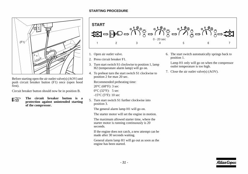
6. The start switch automatically springs back to position 1.Lamp H1 only will go on when the compressor outlet temperature is too high.
7. Close the air outlet valve(s) (AOV).
20 sec4 5 6 7
- 31 -
Before starting open the air outlet valve(s) (AOV) andpush circuit breaker button (F1) once (open hoodfirst).Circuit breaker button should now be in position B.
The circuit breaker button is aprotection against unintended startingof the compressor.
(F1)
STARTING PROCEDURE
1. Open air outlet valve.2. Press circuit breaker F1.3. Turn start switch S1 clockwise to position 1, lam
H2 (temperature alarm lamp) will go on.4. To preheat turn the start switch S1 clockwise to
position 2 for max 20 sec.Recommended preheating time:20°C (68°F): 3 sec0°C (32°F): 5 sec-15°C (5°F): 10 sec
5. Turn start switch S1 further clockwise into position 3.The general alarm lamp H1 will go on.The starter motor will set the engine in motion.The maximum allowed starter time, where the starter motor is running continuously is 20 seconds.If the engine does not catch, a new attempt can bmade after 30 seconds waiting.General alarm lamp H1 will go out as soon as thengine has been started.
0 - 1 2 3

)
Do not open the air outlet valve whenmachine is shut down. Remaining airinside the vessel will be evacuated via ablow down valve automatically! If pressure is released from the vessel tooquickly, oil will start creating foam. Thisfoam could reach the oil separatorelement resulting in oil carry over. Failures caused by not correctly shuttingdown the compressor will not be coveredby warranty!
- 32 -
DURING OPERATION
Regularly carry out following checks:1. That the regulating valve (RV) is correctly
adjusted, i.e. starts decreasing the engine speed when reaching the preset working pressure in the receiver.
2. Check the air filter vacuum indicator (VI). If the yellow piston reaches the red marked service range, replace the filter element. Reset the indicator by pushing the reset button.
Fault situations and protective devices:A fault which occurs with the engine, either oilpressure (too low), coolant temperature (too high),will always and immediately cause the engine to cutout and the alarm lamp H1 will light up.By doing some simple checks, it can be determinedwhat it was that caused the engine to fail: low oillevel, clogged-up cooler.Alarm lamp H2 will light up. The alarm lamp willremain on, until the compressor has been restarted(start switch to position 3), or the contact is turned off(start switch to position 0; also when, due to coolingoff, the thermocontact has closed again (= memoryfunction).
STOPPING PROCEDURE
1. Close the air outlet valves (AOV).2. Run unloaded for 3 minutes.3. Turn the start switch S1 counterclockwise (CCW
to position 0.4. Push the circuit breaker button (F1) once (open
hood first).
When the engine is running, the airoutlet valves (ball valves) must always beput in a fully opened or fully closedposition.
The hood must be closed duringoperation and may be opened for shortperiods only.
3 min
1 2 3 4
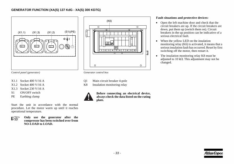
Fault situations and protective devices: Open the left machine door and check that the
circuit breakers are up. If the circuit breakers are down, put them up (switch them on). Circuit breakers in the up position can be indicative of a serious electrical fault.
When the yellow LED on the insulation monitoring relay (K6) is activated, it means that a serious insulation fault has occurred. Reset by first switching off the motor, then restart it.
The insulation monitoring relay K8 must be adjusted to 10 k. This adjustment may not be changed.
e,g
- 33 -
GENERATOR FUNCTION (XA(S) 137 KdG - XA(S) 300 KD7G)
Control panel (generator)
Start the unit in accordance with the normalprocedure. Let the motor warm up until it reachesoperational temperature.
Generator control box
X1.1 Socket 400 V/16 AX1.2 Socket 400 V/16 AX1.3 Socket 230 V/16 AS1 ON/OFF switchPE Earthing clamp
Only use the generator after thecompressor has been switched over fromNO-LOAD to LOAD.
(X1.3) (S1)(X1.2)(X1.1) (PE)
Q1 Main circuit breaker 4-poleK8 Insulation monitoring relay
Before connecting an electrical devicalways check the data listed on the ratinplate.
(K6)
1 2 3 4 5 6 7 8 9 10
(Q1)

eg
g.
n
The maintenance schedule has to be seen as aguideline for units operating in a dusty environmenttypical to compressor applications. Maintenanceschedule can be adapted depending on applicationenvironment and quality of maintenance.
ial p
Every 500 hrs
Every 1000 hrs
Yearly
002912 4517 05 2912 4518 062912 4520 05 2912 4521 06
These service kits offer you the benefits onents. Refer to the parts list for more
x x xx x x
- 34 -
MaintenanceUSE OF SERVICE PAKS
Service Paks include all genuine parts needed fornormal maintenance of both compressor and engine.Service Paks minimize downtime and keep yourmaintenance budget low.Order Service Paks at your local Atlas Copco dealer.
The schedule contains a summary of the maintenancinstructions. Read the respective section before takinmaintenance measures.When servicing, replace all disengaged packings, e.gaskets, O-rings, washers.For engine maintenance refer to Engine OperatioManual.
PREVENTIVE MAINTENANCE SCHEDULE
MAINTENANCE SCHEDULE COMPRESSOR
To determine the maintenance intervals, use service hours, or calendar time, whichever occurs first.Service hours Daily 50 hrs
after initstart-u
Service pakEngine oil filterStandard fuel system
2913 3087
Heavy duty fuel system
For the most important subassemblies, Atlas Copco has developed service kits that combine all wear parts. of genuine parts, save on administration costs and are offered at reduced price, compared to the loose compinformation on the contents of the service kits.
Drain water from fuel filter xCheck on abnormal noise xCheck for leaks in engine-, compressor-, air-, oil-, or fuel system xCheck electrolyte level and terminals of battery x(to be continued on page 35)

ial p
Every 500 hrs
Every 1000 hrs
Yearly
x x xx x xx x xx x xx x xx x xx x xx x xx x xx xx x x
x xx xx xx xx xx xx x
xxx
- 35 -
Maintenance schedule (hrs)(continuation of page 34)
Daily 50 hrsafter init
start-uHoses and clamps - Inspect/Replace xChange engine oil (2) (12) xReplace engine oil filter (2) xCheck electrical system cables for wear xDrain/Clean fuel tank water and sediments (1)Replace fuel (pre)filters (6)Clean oil cooler(s) (1)Inspection by Atlas Copco service technicianCheck torque on critical bolt connectionsCheck engine (minimum and maximum) speedClean after cooler (option) (1)Replace compressor oil filter(s) (5)Grease hingesAdjust engine inlet and outlet valves (2)Replace DD/PD/QD filter (option)Change compressor oil (1) (7)Replace oil separator elementReplace air filter element (1)Check functioning of regulating valveCheck/Test glow plugsTest safety valve (9)(to be continued on page 36)

ial p
Every 500 hrs
Every 1000 hrs
Yearly
xxxx
Keep the bolts of the housing, the liftingeye, the towbar and the axle securelytightened.Refer to section Technical specificationsand section Height adjustment for thetorque values.
- 36 -
Notes
Maintenance schedule (hrs)(continuation of page 35)
Daily 50 hrsafter init
start-uAnalyse Coolant (4) (8)Measure alternator insulation resistance (on optional generatorset)Check rubber flexibles (11)Check emergency stop(to be continued on page 37)
1. More frequently when operating in a dusty environment.2. Refer to engine operation manual.3. After a day’s work.4. Yearly is only valid when using PARCOOL. Change coolant every 5 years.5. Use Atlas Copco oil filters, with by-pass valve as specified in the parts list.6. Gummed or clogged filters means fuel starvation and reduced engine performance.7. See section Lubrication oils.8. Check inhibitors and freezing points using tools
2913 0028 00 : refractometer 2913 0029 00 : pH meter.
9. See section Safety valve.10. See section Before starting.11. Replace all rubber flexibles every 6 years.
For other specific engine and alternator requirements refer to specific manuals.12. Note not applicable.

Every
500 kmEvery
2000 kmYearly
x xx
x x x
x x xx xx x
x xx x
x x xx xx xx xx xx xx x
xx
- 37 -
Maintenance schedule (km)(continuation of page 36)
Daily 50 km after initial
start-upCheck coupling head xCheck height of adjusting facility xCheck drawbar handbrake lever spring actuator, reversing lever, linkage and all movable parts for ease of movement
x x
Check tyre pressure xCheck torque of wheel nuts xGrease coupling head, drawbar bearings at the housing of the overrun brake
x
Check brake system (if installed) and adjust if necessary xOil or grease brake lever and moving parts such as bolts and joints xCheck/Adjust lateral play of wheel bearing (conventional bearing)Check tyres for uneven wearGrease sliding points on height adjusting partsCheck safety cable for damageCheck Bowden cable on height adjustable connection device for damageLubricate torsion bar axle trailing armCheck hub cap for firm seatingCheck brake lining wearChange wheel hub bearing grease

rocarbon oil with rust and oxidation inhibitors and anti-foamsity grade should correspond to the ambient temperature and
das
nto Ittod
orin
eh
lpor
toto
gmer
PAROIL releases excess heat efficiently, whilstmaintaining excellent bore-polish protection to limitoil consumption.PAROIL has an excellent Total Base Number (TBN)retention and more alkalinity to control acidformation.PAROIL prevents Soot build-upPAROIL is optimized for the latest low emissionEURO -3 & -2, EPA TIER II & III engines running onlow sulphur diesel for lower oil and fuel consumption.PAROIL E xtra is a Synthetic ultra high performancediesel engine oil with a high viscosity- index. AtlasCopco PAROIL E xtra is designed to provideexcellent lubrication from start-up in temperatures aslow as -25°C (-13°F).PAROIL E is a mineral based high performancediesel engine oil with a high viscosity- index. AtlasCopco PAROIL E is designed to provide a high levelof performance and protection in ‘standard’ ambientconditions as from -15°C (5°F).
between -10°C (14°F) and +50°C (122°F)between -20°C (-4°F) and +50°C (122°F)
between -10°C (14°F) and +50°C (122°F)between -25°C (-13°F) and +50°C (122°F)
- 38 -
FUEL
For fuel specifications, please contact your AtlasCopco Customer Center.
LUBRICATION OILS
High-quality, mineral, hydraulic or synthesized hydand anti-wear properties is recommended. The viscoISO 3448, as follows:
PAROIL from Atlas Copco is the ONLY oil testeand approved for use in all engines built into AtlCopco compressors and generators.Extensive laboratory and field endurance tests oAtlas Copco equipment have proven PAROIL match all lubrication demands in varied conditions.meets stringent quality control specifications ensure your equipment will run smoothly anreliably.The quality lubricant additives in PAROIL allow fextended oil change intervals without any loss performance or longevity.PAROIL provides wear protection under extremconditions. Powerful oxidation resistance, higchemical stability and rust- inhibiting additives hereduce corrosion, even within engines left idle fextended periods.PAROIL contains high quality anti-oxidants control deposits, sludge and contaminants that tend build up under very high temperatures.PAROIL’s detergent additives keep sludge forminparticles in a fine suspension instead of allowing theto clog your filter and accumulate in the valve/rockcover area.
Compressor PAROIL MPAROIL S
Engine PAROIL EPAROIL E xtra

US gal Order number1.3 1615 5947 005.2 1615 5948 0055 1615 5949 00
US gal Order number1.3 1630 0160 005.2 1630 0161 0055 1630 0162 00264 1630 0163 00
US gal Order number1.3 1615 5953 005.2 1615 5954 0055 1615 5955 00264 1630 0096 00
US gal Order number1.3 1630 0135 005.2 1630 0136 00
- 39 -
*If you want to use another brand of oil,consult the Engine Operation Manual.
**It is strongly recommended to use AtlasCopco branded lubrication oils for bothcompressor and engine. If you want touse another brand of oil, consult AtlasCopco.
Never mix synthetic with mineral oil.Remark: When changing from mineral tosynthetic oil (or the other way around),you will need to do an extra rinse:After doing the complete changeprocedure to synthetic oil, run the unitfor a few minutes to allow good andcomplete circulation of the synthetic oil.Then drain the synthetic oil again andfill again with new synthetic oil. To setcorrect oil levels, proceed as in normalinstruction.
Mineral compressor oil PAROIL M
Synthetic compressor oil PAROIL S
Mineral engine oil PAROIL E
Synthetic engine oil PAROIL E xtra
Litercan 5can 20barrel 210
Litercan 5can 20barrel 210container 1000
Litercan 5can 20barrel 210container 1000
Litercan 5can 20

e)n
),y
- 40 -
OIL LEVEL CHECK
CHECK ENGINE OIL LEVEL
Consult also the Engine Operation Manual for the oilspecifications, viscosity recommendations and oilchange intervals.For intervals, see Preventive maintenance schedule.Check engine oil level according to the instructions inthe Engine Operation Manual and top up with oil ifnecessary.
CHECK COMPRESSOR OIL LEVEL
With the unit standing level, check the level of thcompressor oil. The pointer of the oil level gauge (1must register in the upper extremity of the greerange. Add oil if necessary.
Never mix oils of different brands ortypes.Use only non-toxic oils where there is arisk of inhaling delivered air.
Before removing oil filler plug (2ensure that the pressure is released bopening an air outlet valve.
(2)
(1)

e
eilal
yd
t
y
2. Drain the oil by removing all relevant drain plugs. Drain plugs are located at the air receiver, compressor element and compressor oil cooler. Catch the oil in a drain pan. Screw out the filler plug to speed up draining. Tighten the plugs after draining.
3. Remove the oil filter (1), e.g. by means of a special tool. Catch the oil in a drain pan.
4. Clean the filter seat on the manifold, taking care that no dirt drops into the system. Oil the gasket of the new filter element. Screw it into place until the gasket contacts its seat, then tighten one half turn only.
5. Fill the air receiver until the pointer of the oil level gauge (3) registers in the upper extremity of the green range. Take care that no dirt drops into the system. Reinstall and tighten the filler plug.
6. Run the unit at no load for a few minutes to circulate the oil and to evacuate the air trapped in the oil system.
7. Stop the compressor. Let the oil settle for a few minutes. Check that the pressure is released by opening an air outlet valve. Screw out filler plug (2) and add oil until the pointer of the oil level gauge (3) again registers in the upper extremity of the green range. Reinstall and tighten the filler plug.
GE
Never add more oil. Overfilling results inoil consumption.
- 41 -
OIL AND OIL FILTER CHANGE
ENGINE OIL AND OIL FILTER CHANGE
For replacing the engine oil filter, see sectionPreventive maintenance schedule.
The quality and the temperature of the oil determinthe oil change interval.The prescribed interval (see section Preventivmaintenance schedule) is based on an otemperature of up to 100 °C (212 °F) and normoperating conditions.When operating in high ambient temperatures, in verdusty or high humidity conditions, it is recommendeto change the oil more frequently.
1. Run the compressor until warm. Close the outlevalve(s) and stop the compressor. Wait until the pressure is released through the automatic blow-down valve. Unscrew the oil filler plug (2) one turn. This uncovers a vent hole, which permits anpressure in the system to escape.
In this case, contact Atlas Copco.
COMPRESSOR OIL AND OIL FILTER CHAN
(3)
(1) (2)

.
,
Vessel cover contaminated clean
Vesselcontaminated clean
ging interval, draining is sufficient
PAROIL S PAROIL S xtremeflushing flushing
draining * drainingdraining draining *
- 42 -
COMPRESSOR OIL FLUSHING PROCEDURE
To avoid problems when changing over to a new typeof oil (see table) a special Compressor Oil FlushingProcedure has to be followed. The table is only validin case the replaced oil has not exceeded its lifetime.For more information consult Atlas Copco Servicedept.Aged oil can be recognized best by using an oilsampling analysis program. Indicators for aged oil arestrong smell, or contamination like sludge andvarnish inside the oil vessel and oil stop valve or abrownish colour of the oil.Whenever aged oil is discovered, eg. when changingthe oil separator, contact Atlas Copco Service dept. tohave your compressor cleaned and flushed.1. First thoroughly drain the system when the oil is
warm, leaving as little oil in the system as feasible especially in dead areas, if possible blow out remaining oil by pressurising the oil system. Check the instruction manual for detailed description.
2. Remove the compressor oil filter(s).3. Open the oil vessel and remove the oil separator
element.
4. Check the interior of the oil vessel (see pictures)If varnish deposits are discovered, contact AtlasCopco Service dept. and do not continue.
5. Put in a new oil separator, screw on new compressor oil filter(s) and close the oil vessel according to the instructions.
6. Fill the oil vessel with the minimum amount of replacement oil, run the compressor under light load conditions for 30 minutes.
7. Thoroughly drain the system when the oil is warm, leaving as little oil in the system as feasibleespecially in dead areas, if possible blow out remaining oil by pressurising the oil.
8. Fill the system with the final oil charge.9. Run the compressor under light load conditions
for 15 minutes and check for leakage. 10. Check the oil level and top up if necessary.11. Collect all waste lubricant used during the
flushing process and dispose of it in accordancewith the applicable procedures for managing waste lubricant.
Not respecting compressor oil changingintervals according to the maintenanceschedule, can lead to serious problems,including fire hazard! The manufacturerdoes not accept any liability for damagearising from not following themaintenance schedule or not usinggenuine parts.
Instructions on replacing the oilseparator element are available fromAtlas Copco Service dept. * When changing over to the same oil within the oil chan
** Change over not recommended
PAROIL MPAROIL M draining *PAROIL S draining **PAROIL S xtreme draining **

t
lee.
gst
l,r
- 43 -
CLEANING COOLERS
Keep the coolers clean to maintain the coolingefficiency.
Remove the baffle (1). Then clean by air jet in reversedirection of normal flow.
Steam cleaning in combination with a cleansing agenmay be applied.
Install the baffle (1).
Remove any dirt from the coolers with afibre brush. Never use a wire brush ormetal objects.
(1)
To avoid damaging the coolers, angbetween jet and coolers should bapprox. 90° (do not use jet at maxpower) .
Protect the electrical and controllinequipment, air filters, etc. againpenetration of moisture.
Never leave spilled liquids such as fueoil, water and cleansing agents in oaround the compressor.
e
RECHARGING A BATTERY
Before and after charging a battery, always check theelectrolyte level in each cell; if required, top up withdistilled water only. When charging batteries, eachcell must be open, i.e. plugs and/or cover removed.
Apply with preference the slow charging method andadjust the charge current according to the followingrule of thumb:battery capacity in Ah divided by 20 gives safecharging current in Amp.
BATTERY MAINTENANCE
Keep the battery clean and dry. Keep the electrolyte level at 10 mm (0.4 in) to
15 mm (0.6 in) above the plates or at the indicated level; top up with distilled water only.
Keep the terminals and clamps tight, clean, and lightely covered with petroleum jelly.
Use a commercial automatic batterycharger according to its manufacturer’sinstructions.
- 44 -
BATTERY CARE
If the battery is still dry, it must be activated asdescribed in section Activating a dry-chargedbattery.The battery must be in operation within 2 monthsfrom being activated; if not, it needs to be rechargedfirst.
ELECTROLYTE
Electrolyte in batteries is a sulphuric acid solution indistilled water.The solution must be made up before beingintroduced into the battery.
ACTIVATING A DRY-CHARGED BATTERY
Take out the battery. Battery and electrolyte must be at equal
temperature above 10°C (50°F). Remove cover and/or plug from each cell. Fill each cell with electrolyte until the level
reaches 10 mm (0.4 in) to 15 mm (0.6 in) abovethe plates, or to the level marked on the battery.
Rock the battery a few times so that possible airbubbles can escape; wait 10 minutes and check thlevel in each cell once more; if required, add electrolyte.
Refit plugs and/or cover. Place the battery in the compressor.
Before handling batteries, read therelevant safety precautions and actaccordingly.
Read the safety instructions carefully.

a
at
e
ic
att.e
COMPRESSOR ELEMENT OVERHAUL
When a compressor element is due for overhaul, it isrecommended to have it done by Atlas Copco. Thisguarantees the use of genuine parts and correct toolswith care and precision.
LIABILITY
The manufacturer does not accept any liability for anydamage arising from the use of non-original parts andfor modifications, additions or conversions madewithout the manufacturer’s approval in writing.
- 45 -
STORAGE
Run the compressor regularly, e.g. twice a week, untilwarm.Load and unload the compressor a few times tooperate the unloading and regulating components.Close the air outlet valves after stopping.
SERVICE PAKS
A Service Pak is a collection of parts to be used forspecific maintenance measure.It guarantees that all necessary parts are replaced the same time keeping down time to a minimum.The order number of the Service Paks are listed in thAtlas Copco Parts List.
SERVICE KITS
A service kit is a collection of parts to fit a specifrepair or rebuilding task.It guarantees that all necessary parts are replaced the same time which improves the uptime of the uniThe order numbers of the Service Kits are listed in thAtlas Copco Parts List.
If the compressor is going to be storedwithout running from time to time,protective measures must be taken.
Contact Atlas Copco.

The working pressure is determined by the tension ofthe spring in the regulating valve (RV). This tensioncan be increased to raise the pressure and decreased tolower it by turning the adjusting wheel clockwise andanti-clockwise respectively.
The solenoid valve (SOV) is only presentat units equipped with a generator(XA(S) 137 KdG - XA(S) 300 KD7G).
- 46 -
Adjustments and servicing proceduresADJUSTMENT OF THE CONTINUOUS PNEUMATIC REGULATING SYSTEM
(SOV)
(AR)
(AOV)
(RV)
(SR)
(E)
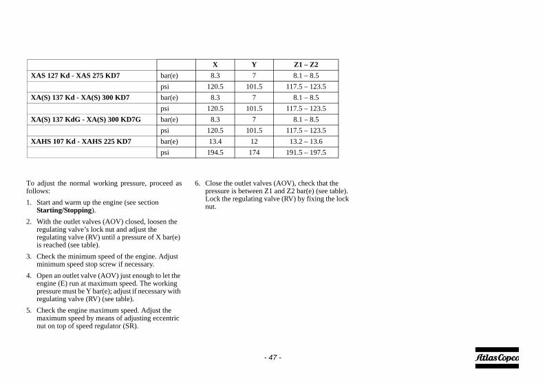
. k
- 47 -
To adjust the normal working pressure, proceed asfollows:1. Start and warm up the engine (see section
Starting/Stopping).2. With the outlet valves (AOV) closed, loosen the
regulating valve’s lock nut and adjust the regulating valve (RV) until a pressure of X bar(e) is reached (see table).
3. Check the minimum speed of the engine. Adjust minimum speed stop screw if necessary.
4. Open an outlet valve (AOV) just enough to let the engine (E) run at maximum speed. The working pressure must be Y bar(e); adjust if necessary with regulating valve (RV) (see table).
5. Check the engine maximum speed. Adjust the maximum speed by means of adjusting eccentric nut on top of speed regulator (SR).
6. Close the outlet valves (AOV), check that the pressure is between Z1 and Z2 bar(e) (see table)Lock the regulating valve (RV) by fixing the locnut.
X Y Z1 – Z2XAS 127 Kd - XAS 275 KD7 bar(e) 8.3 7 8.1 – 8.5
psi 120.5 101.5 117.5 – 123.5XA(S) 137 Kd - XA(S) 300 KD7 bar(e) 8.3 7 8.1 – 8.5
psi 120.5 101.5 117.5 – 123.5XA(S) 137 KdG - XA(S) 300 KD7G bar(e) 8.3 7 8.1 – 8.5
psi 120.5 101.5 117.5 – 123.5XAHS 107 Kd - XAHS 225 KD7 bar(e) 13.4 12 13.2 – 13.6
psi 194.5 174 191.5 – 197.5

CLEANING THE DUST TRAP
Remove dust daily.To remove dust from the dust trap pinch the vacuatorvalve (6) several times.
CLEANING INSTRUCTIONS FILTER ELEMENT
If element cleaning can not be avoided, care should betaken that the filter element (4) is not washed out.Please note that engine damage can causeconsiderable costs, which makes the cost of a newfilter element seam insignificant.Safety cartridges (3) can not be cleaned but must beexchanged.Please note that a cleaned element will never matchthe service life and performance of a new element.Take the element from the air filter housing (5) (seesection Replacing the air filter element).
- 48 -
AIR FILTER ENGINE/COMPRESSOR
SERVICING
Always select the service point according to thevacuum indicator or display message. A regularinspection or cleaning as it is sometimes practiced inthe field is more likely to be damaging than useful asthere is a risk that the element will be damaged anddust will gain access to the engine.Atlas Copco always recommends exchangingrather than cleaning the filter element in order toavoid damage and ensure maximum engineprotection.
MAIN PARTS
The Atlas Copco air filters are speciallydesigned for the application. The use ofnon-genuine air filters may lead tosevere damage of engine and/orcompressor element.Never run the compressor without airfilter element.
1. Snap clips 6. Vacuator valve2. Dust trap cover 7. Vacuum indicator3. Safety cartridge
(option)8. Reset button
4. Filter element 9. Yellow indicator5. Filter housing
(1)
(6)(2) (3)(4) (5)(7)(9)
(8)

New elements must also be inspected for tears orpunctures before installation.Discard the element (4) when damaged.In heavy duty applications it is recommended toinstall a safety cartridge which can be ordered withpart no.: 2914 9311 00.A dirty safety cartridge (3) is an indication of a mal-functioning air filter element. Replace the elementand the safety cartridge in this case.The safety cartridge cannot be cleaned.
1. Release the snap clips (1) and remove the dust trap (2). Clean the trap.
2. Remove the element (4) and the safety cartridge.3. Reassemble in reverse order of dismantling. Make
sure the vacuator valve (6) points down.4. Inspect and tighten all air intake connections.5. Reset the vacuum indicator by pressing the reset
button (5).
- 49 -
In order to clean, position a pipe with an end bent byapprox. 90° on the end of a compressed-air pistol. Thepipe must be long enough to reach the bottom of thefilter element. Carefully blow out the filter elementwith dry compressed air (max. 5 bar (72.5 psi)) fromthe inside to the outside until there is no moredevelopment of dust. The end of the pipe must nottouch the element.Next carefully examine the element for possibledamage. Never beat or knock the element as this willdamage it and there will be a danger of damage to theengine.Carefully clean the inside of the housing and put theelement in the housing (see section Replacing the airfilter element).
REPLACING THE AIR FILTER ELEMENT
(1)
(2) (3)(4) (5)(6)
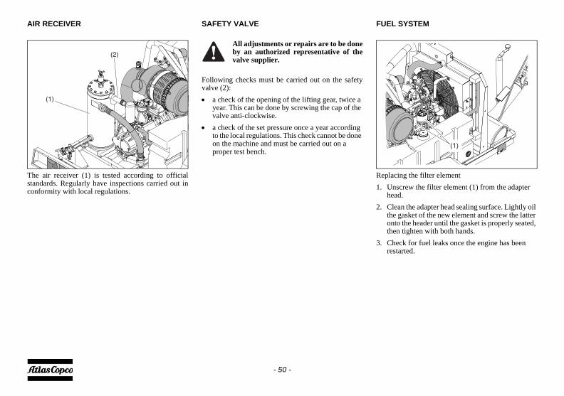
y
a e
e
FUEL SYSTEM
Replacing the filter element1. Unscrew the filter element (1) from the adapter
head.2. Clean the adapter head sealing surface. Lightly oil
the gasket of the new element and screw the latter onto the header until the gasket is properly seated, then tighten with both hands.
3. Check for fuel leaks once the engine has been restarted.
ee
(1)
- 50 -
AIR RECEIVER
The air receiver (1) is tested according to officialstandards. Regularly have inspections carried out inconformity with local regulations.
SAFETY VALVE
Following checks must be carried out on the safetvalve (2): a check of the opening of the lifting gear, twice
year. This can be done by screwing the cap of thvalve anti-clockwise.
a check of the set pressure once a year accordingto the local regulations. This check cannot be donon the machine and must be carried out on a proper test bench.
(1)
(2)
All adjustments or repairs are to be donby an authorized representative of thvalve supplier.

he
d.h
eg
Lift and support the compressor. Make sure that allbrakes are off (overrunbrake and hand brake lever).The brake cables must be free from tension. Lock theswivel cams of the wheel brake from the outside bymeans of a pin 4 mm (4) through the hole as shownin the Figure.Turn the adjusting bolt (1) clockwise with a wrenchtill the wheel locks up. Center the brake shoes byactuating the parking brake several times.Turn the adjusting bolt anti-clockwise until the wheelis running free in direction of travel (approx. 1 fullturn of the adjusting bolt).Check the position of the equalizer (see sectionBrake cable adjustment, 6) with the parking brakeactuated.Perpendicular position of equalizer = identicalclearance of wheel brakes.Re-adjust the brake shoes, if necessary.To test, slightly apply the parking brake and checkidentical brake torque on left and right side.Remove locking pin (4). Remove clearance frombrake cables. Check all lock nuts (Brake cable adjustment, 2).
- 51 -
BRAKE (= OPTION) ADJUSTMENT BRAKE SHOE ADJUSTMENT
Check the thickness of the brake lining. Remove botblack plastic plugs (5), one on each wheel. When thbrake lining has been worn to a thickness of 1 mm(0.039 in) or less, the brake shoes have to be replaceAfter inspection and/or replacement re-insert botplugs.Brake shoe adjustment re-establishes the braklining-to-drum clearance and compensates for lininwear.
Before jacking up the compressor,connect it to a towing vehicle or attach aweight of minimum 50 kg (110 lb) to thetowbar.
1. Adjusting bolt 4. Pin 4 mm2. Axle 5. Plug3. Brake cable
(1)(5) (3) (2)
(4)

BRAKE ADJUSTMENT CHECK
This check has to be performed when brake partswere replaced.1. Check if the towing eye rod of the overrun brake
mechanism is in the outmost position.2. Check if the adjustable towbar (= option) is in the
actual towing position.3. Apply the hand brake lever.4. Push the compressor a few centimeters backwards
so that the brake lever is automatically pulled further up.
Check the reference angle. The angle from the controldevice top cover to the inside of the pulled handbrakelever must be 110° +4°.Adjust if necessary.
�+4˚
110˚+0˚
- 52 -
BRAKE CABLE ADJUSTMENT
1. With the towing eye pulled out in the outmost position and the hand brake lever in the downward position, loosen the lock nuts (2). Turn adjusting nuts and brake cable nuts (4) clockwise until there is no slack in the brake mechanism.The equalizer (6) must remain perpendicular to main brake cable (5).
2. Apply the hand brake lever several times and repeat the adjustment. Tighten the nuts with their lock nuts (2). Remove the jack and the blocks.
3. Road test the compressor and brake several times. Check brake shoe and brake cable adjustment and if necessary adjust.
1. Brake cable 4. Brake cable nut2. Lock nut 5. Main brake cable3. Adjusting nut 6. Equalizer
(4) (2)(1) (6)
(1) (3) (4) (2)(2) (5)

ll
e
o.e.
l)
or
Greasing bearing race
Fill the hub caps to 3/4 full with grease.Fit wheel hubs, adjust the bearing play and fit the hubcaps.Grease: part number 1626 5402 80
- 53 -
WHEELS
WHEEL CHECK
Check wheel bolts for firm seating (initially) Check hub caps for firm seating (every 2,500 km
or anually) Check tyres for uneven wear (every 2,500 km or
anually) Check lateral play of wheel bearing. If necessary,
readjust.Compact bearings (every 2 years)Conventional bearings (after 500 km, every 2,500 km or anually)
LUBRICATION
Tapered type hub cap
Taper roller bearings and deep groove babearingAxles fitted with taper roller bearings arrecognizable by a tapered type hub cap, see Figure.Remove wheels and wheel hubs.Mark dismounted wheel hubs and bearing races sthat their identity is not mistaken during reassemblyClean wheel hubs thoroughly inside and outsidRemove old grease totally.Clean taper roller bearings and seals (using diesel oiand check for reuseability.Work BPW special longlife grease ECO_Li 91 intthe cavities between the taper roller and cage. Smeagrease into the hub's outer bearing race.

h.
Tightening torques of wheel bolts
h
Spannerwidth (mm)
Thread Tighteningtorque
17 (19) M 12x1.5 80 100 Nm
19 M 14x1.5 110 120 Nm
24 M 18x1.5 270 280 Nm
- 54 -
Cylindrical hub cap shape
Compact bearingsCompact bearings are recognizable by cylindrical hubcap shape, see Figure.Compact bearings are maintenance-free due topermanent lubrication and are designed for highmileages.Therefore, there is no grease change or regreasingnecessary.
WHEEL BOLTS CHECK
Wheel bolts tightening
Tighten wheel bolts crosswise using a torque wrencto the tightening torque in compliance with the table
After the first run, likewise after eacwheel change.

al
t y
n
e
Compact bearingsCompact bearings are recognizable by theircylindrical hub cap shape.
If noticeable bearing play is felt, thecompact bearings should be replaced.
- 55 -
WHEEL BEARING ADJUSTMENT
Bearing play
Jack up the compressor, release brakes.Turn wheels manually and rock. If any bearing play is perceivable, adjust the bearings.
Conventional taper roller bearingsTaper roller bearings are recognisable by the conicprofile of the hub cap. Lever off hub cap. Remove split pin from axle nu
and tighten so that rotation of the wheel is slightlbraked.
Turn back the axle nut to the next possible split pihole, by a maximum of 30 degrees.
Insert split pin and bend ends slightly outwards. Check wheel rotation, fit hub cap.
Important:The grease in the hub cap and bearing must not bcontaminated with dirt during this job!

e.
ct
Brake play
The check is carried out visually on the stroke (x) ofthe overrun coupling.As soon as this is more than 50 mm when the brakesare applied, adjust the wheel brakes.Check towbar, handbrake lever, spring actuator,reversing lever, linkage and all movable parts for easeof movement.
0s
After the first run, then every 2,000 -3,000 kilometres.
(x)
- 56 -
TOWBAR AND OVERRUN BRAKE CHECK
Coupling head
Check coupling head for wear and correct operation.Check the wear indicator (use within the "+" rangeonly). Check the coupling head fastenings (see arrows,Figure) at regular intervals for firm seating.
Height adjustment facility
After every adjustment the clamping nuts (1) must bscrewed up tight and secured with the spring pin (2)Tightening torque:M 24 = 250 - 350 NmM 32 = 350 - 400 NmCheck tight fit of the clamping nuts and correpositioning of the adjustment facility.
Initially, then every 5,000 kilometres orannually.
Initially, before every journey, after 50kilometres, then every 5,000 kilometreor annually.
(2)
(1)
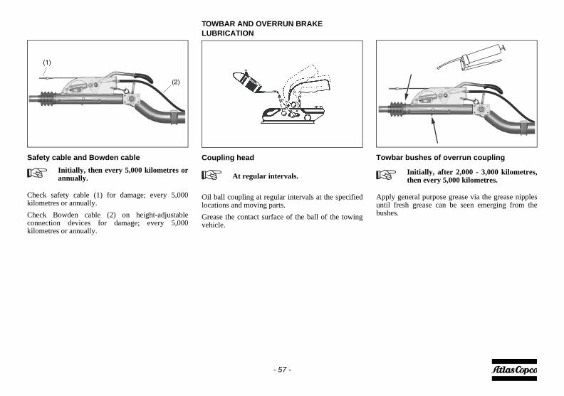
d
g
Towbar bushes of overrun coupling
Apply general purpose grease via the grease nipplesuntil fresh grease can be seen emerging from thebushes.
Initially, after 2,000 - 3,000 kilometres,then every 5,000 kilometres.
- 57 -
Safety cable and Bowden cable
Check safety cable (1) for damage; every 5,000kilometres or annually.Check Bowden cable (2) on height-adjustableconnection devices for damage; every 5,000kilometres or annually.
TOWBAR AND OVERRUN BRAKE LUBRICATION
Coupling head
Oil ball coupling at regular intervals at the specifielocations and moving parts.Grease the contact surface of the ball of the towinvehicle.
Initially, then every 5,000 kilometres orannually.
(2)
(1)
At regular intervals.

g
0.
- 58 -
Reversing lever, moving parts and pivot pins
Check reversing lever for ease of motion.If fitted, apply general purpose grease via the greasenipple until fresh grease can be seen emerging fromthe bush.If grease nipples are not fitted, then apply oil to thereversing lever bush.All moving parts of drawbar, handbrake lever, springactuator, reversing lever, linkages etc. are to be oiledor greased as required.
Sliding locations on the height-adjustindevice
Oil threaded parts and grease toothed parts.
Initially, after 2,000 - 3,000 kilometres,then every 5,000 kilometres. For the first time, after 2,000 - 3,00
kilometres, then every 5,000 kilometres

at
orrective actions
Check electrolyte level and charge battery. If no cells are shorted and battery is discharged, trace cause and correct.
See corrective action 1.
Check and correct if necessary.Have assembly repaired.
Replace.
Release button after engine oil pressure has built up above the minimum allowed level.Stop at once, consult the engine instruction manual.Fill fuel tank.
Check and, if necessary consult Atlas Copco.Check hoses and their fittings. Stop leaks; replace leaking hoses.
- 59 -
Problem solvingIt is assumed that the engine is in good condition andthat there is adequate fuel flow to the filter andinjection equipment.
Make sure that the wires are not damaged and ththey are clamped tight to their terminals.
An electrical fault must be traced by anelectrician.
Problem Possible faults C
1. Starter motor does not crank engine after switching startbutton (S) to ” ”.
a. Low battery output. a.
2. Starter motor cranks engine when switching start button (S) to ” ”, but engine does not fire.
a. Low battery output. a.
3. Engine fires, but engine stops when releasing start button (S).
a. Alternator drive belt broken or slipping.b. Alternator/regulator defective.
a.b.
4. Hourmeter (P1) does not count running time.
a. Hourmeter (P1) defective. a.
5. Engine is running, but shuts down immediately after start button (S) has been released.
a. Start button (S) released too soon.
b. Insufficient engine oil pressure.c. Fuel tank contains insufficient fuel.
a.
b.c.
6. Compressor is loaded automatically to full capacity after starting.
a. Air intake throttle valve stuck in opened position.b. Air leaks in regulating system.
a.b.

Check and, if necessary consult Atlas Copco.Check and, if necessary consult Atlas Copco.
Check oil level. Release pressure and drain oil to correct level.
Check equipment connected.Remove and inspect elements.Check and, if necessary consult Atlas Copco.
Check and, if necessary consult Atlas Copco.Check hoses and their fittings. Stop leaks and, if necessary consult Atlas Copco.Check and, if necessary consult Atlas Copco.
Check and, if necessary consult Atlas Copco.Check hoses and their fittings. Stop leaks and, if necessary consult Atlas Copco.Check and, if necessary consult Atlas Copco.Check safety valve; consult Atlas Copco.
Fill fuel tank.Check filters and hoses for leaks, dirt and bends.Refer to the engine instruction manual.See corrective actions 14.See corrective actions 15.Top up cooling system.
Check and, if necessary consult Atlas Copco.Consult Atlas Copco.
orrective actions
- 60 -
7. Engine does not speed up immediately after compressor loading valve button has been pressed and compressor does not deliver air.
a. Regulating valve defective.b. Air intake throttle valve stuck in closed position.
a.b.
8. Excessive compressor oil consumption. Oil mist being discharged from air outlet valves.
a. Compressor oil level too high. a.
9. Compressor capacity or pressure below normal.
a. Air consumption exceeds capacity of compressor.b. Choked air filter elements.c. Unloading valve not completely open.
a.b.c.
10. Compressor does not unload and engine keeps running at max. speed when closing the air outlet valves, safety valve blows.
a. Regulating valve incorrectly set or defective.b. Air leaks in regulating system.
c. Unloading valve stuck.
a.b.
c.
11. Working pressure rises during operation and causes safety valve to blow.
a. Regulating valve incorrectly set or defective.b. Air leaks in regulating system.
c. Unloading valve stuck.d. Safety valve defective.
a.b.
c.d.
12. After working some time, the unit stops through a shutdown switch.
a. Fuel tank contains insufficient fuel.b. Air in fuel system, or insufficient fuel supply.c. Engine oil pressure too low.d. Engine temperature too high.e. Compressor temperature too high.f. Low coolant level.
a.b.c.d.e.f.
13. Air and oil mist expelles from air filters immediately after stopping.
a. Unloader valve jammed.b. Wrong oil type (without foam-retarding additives).
a.b.
Problem Possible faults C

Relocate compressor.Clean engine oil cooler. Refer to section Cleaning coolers.
Locate compressor away from walls; when banked with other compressors, leave space between them.Clean oil cooler. Refer to section Cleaning coolers.Check oil level. Top up with recommended oil.
Check filters and hoses for leaks, dirt and bends.
orrective actions
- 61 -
Alternator precautions1. Never reverse the polarity of the battery or the
alternator.2. Never break any alternator or battery connections
while the engine is running.3. When recharging the battery, disconnect it from
the alternator. Before using booster cables to start the engine, be sure of the polarity and connect the batteries correctly.
4. Never operate the engine without the main or voltage sensing cables connected in the circuit.
14. Engine overheating. a. Insufficient engine cooling.b. Engine oil cooler clogged externally.
a.b.
15. Compressor overheating. a. Insufficient compressor cooling.
b. Oil cooler clogged externally.c. Oil level too low.
a.
b.c.
16. After working for some time, the unit stops for no apparent reason.
a. Air in fuel system, or insufficient fuel supply. a.
Problem Possible faults C

ur local safety regulations and are available with overrun .ts for safety on the road. the aftercooler, reheater and fine filters.
nt: Aftercooler + water separatorAftercooler + water separator + fine filter PDAftercooler + water separator + fine filter DD + PDAftercooler + water separator + fine filter PD + reheater (C)Aftercooler + water separator + fine filter DD + PD + reheater (C)Aftercooler + water separator + reheaterLubricator on 7 bar units-20 °C (-4 °F)SingleDoubleTriple
- 62 -
Available options
A. These units meet yoand parking brakes
B. Reflectors and lighC. Quality air through
Vessel type: EUROASME
Towbar: Adjustable with brakes (A)Fixed with brakes (A)Fixed without brakes
Without towbar: Support (without undercarriage)Towing eyes: Atlas Copco
DINBallItalianNATOAC (France)
Towbar support: Support legJockey wheel
Road signalisation: Full (B)Safety: Wheel chocks
Safety cartridgeRefinery equipment: Spark arrestor
Inlet shut down valve
Air quality equipme
Cold start:Customer colour:

SSEMBLIES
Torque value (Nm / lbf.ft)120 (89) +/- 10%205 (151) +/- 10%80 (59) +/- 10%205 (151) +/- 10%
bar 80 (59) +/- 10%heel housing 80 (59) +/- 10%using (M12) 80 (59) +/- 10%using (M14) 125 (92) +/- 10%ment/drive 80 (59) +/- 5%
35 (26) +/- 10%ar (M24) 275 (203) +/- 10%ar (M32) 375 (277) +/- 5%
rain cock and tank cap of the fuel tank handtight.
- 63 -
Technical specificationsTORQUE VALUES
FOR GENERAL APPLICATIONS
The following tables list the recommended torques applied for general applicationsat assembly of the compressor.
For hexagon screws and nuts with strength grade 8.8
For hexagon screws and nuts with strength grade 12.9
FOR IMPORTANT A
Thread size Torque value (Nm / lbf.ft) M6 9 (6.5)M8 23 (17)M10 46 (35)M12 80 (59)M14 125 (92)M16 205 (151)
Thread size Torque value (Nm / lbf.ft) M6 15 (11)M8 39 (29)M10 78 (58)M12 135 (100)M14 210 (155)M16 345 (255)
AssembliesWheel nutsBolts, axle/beamsBolts, towbar/axleBolts, towbar/bottomBolts, towing eye/towBolts, lifting eye/flywBolts, engine/drive hoBolts, engine/drive hoBolts, compressor elehousingSafety switchesJoints adjustable towbJoints adjustable towb
Secure the d

S) 137 Kd - S) 300 KD7
XA(S) 137 KdG - XA(S) 300 KD7G
XAHS 107 Kd - XAHS 225 KD7
230/400 V1 1 1
14.5 14.5 14.50 0 0
20 20 2068 68 687 7 12
102 102 174
- 64 -
COMPRESSOR/ENGINE/GENERATOR SPECIFICATIONS
REFERENCE CONDITIONS
The inlet conditions are specified at the air inlet grating outside the canopy.
Designation XAS 127 Kd - XAS 275 KD7
XA(XA(
Absolute inlet pressure bar(e) 1psi 14.5
Relative air humidity % 0Air inlet temperature °C 20
°F 68Nominal effective working pressure bar(e) 7
psi 102

S) 137 Kd - S) 300 KD7
XA(S) 137 KdG - XA(S) 300 KD7G
XAHS 107 Kd - XAHS 225 KD7
230/400 V4.14 4 460 58 58
8.21 13.5 13.5119.1 195.8 195.8
45 50 50113 122 12240 40 40104 104 104- 10 - 10 - 1014 14 14
- 20 - 20 - 20- 4 - 4 - 4
see curves
- 65 -
LIMITATIONS
Designation XAS 127 Kd - XAS 275 KD7
XA(XA(
Minimum effective receiver pressure bar(e) 5.12psi 74
Maximum effective receiver pressure, compressor unloaded bar(e) 9.1psi 132
Maximum ambient temperature at sealevel
standard °C 50°F 122
aftercooler option
°C 45°F 113
Minimum starting temperature °C - 10°F 14
Minimum starting temperature, with coldstart equipment 1) °C - 20°F - 4
Altitude capability
1) Coldstart: Compressor: PAROIL S i.s.o. PAROIL MEngine: PAROIL E xtra i.s.o. PAROIL E

,0 0,0 10,0 20,0 30,0 40,0 50,0
4 32 50 68 86 104 12213.124
9.843
6.562
3.281
0 ft
S) 137 Kd
S) 300 KD7
7 bar
102 psi
ALT
ITU
DE
IN F
T
TEMPERATURE IN °F
TEMPERATURE IN °C
- 66 -
Performance dataMax. allowable working pressure as a function of altitude and ambient temperature.
6000
5000
4000
3000
2000
1000
0
14 32 50 68 86 104 122
-10,0 0,0 10,0 20,0 30,0 40,0 50,0
16.405
13.124
9.843
6.562
3.281
0 ft
7 bar102 psi
XAS 127 Kd
XAS 275 KD7
ALT
ITU
DE
IN M
ALT
ITU
DE
IN F
T
TEMPERATURE IN °F
TEMPERATURE IN °C
4000
3000
2000
1000
0-10
1
XA(
XA(
ALT
ITU
DE
IN M

0,0 0,0 10,0 20,0 30,0 40,0 50,0
4 32 50 68 86 104 12213.124
9.843
6.562
3.281
0 ft
S 107 Kd
S 225 KD7
12 bar
175 psi
ALT
ITU
DE
IN F
T
TEMPERATURE IN °F
TEMPERATURE IN °C
- 67 -
4000
3000
2000
1000
0-10,0 0,0 10,0 20,0 30,0 40,0 50,0
14 32 50 68 86 104 12213.124
9.843
6.562
3.281
0 ft
XA(S) 137 KdG
XA(S) 300 KD7G
7 bar
102 psi
ALT
ITU
DE
IN M
ALT
ITU
DE
IN F
T
TEMPERATURE IN °F
TEMPERATURE IN °C
4000
3000
2000
1000
0-1
1
XAH
XAH
ALT
ITU
DE
IN M

S) 137 Kd - S) 300 KD7
XA(S) 137 KdG - XA(S) 300 KD7G
XAHS 107 Kd - XAHS 225 KD7
230/400 V2400 2400 24001700 1700 1700138 109 106292 231 225133 105 102281 222 216
- 68 -
PERFORMANCE DATA
At reference conditions, if applicable, and at normal shaft speed, unless otherwise stated.
1) Free Air Delivery (volume flow rate) is measured according to ISO 1217 ed.3 1996 annex D
Tolerance: +/- 5% 25 l/s (53 cfm) < FAD < 250 l/s (530 cfm) +/- 4% 250 l/s (530 cfm) < FADThe international standard ISO 1217 corresponds to following national standards: British BSI 1571 part 1 German DIN 1945 Part 1 Swedish SS-ISO 1217 American ANSI PTC9
Designation XAS 127 Kd - XAS 275 KD7
XA(XA(
Engine shaft speed, normal and maximum r/min 2400Engine shaft speed, compressor unloaded r/min 1700Free air delivery 1) standard l/s 128
cfm 271with aftercooler l/s 123
cfm 261

S) 137 Kd - S) 300 KD7
XA(S) 137 KdG - XA(S) 300 KD7G
XAHS 107 Kd - XAHS 225 KD7
230/400 V12.6 12.6 12.627.7 27.7 27.710.1 10.1 10.122.2 22.2 22.28.0 8.4 8.4
17.6 18.5 18.56.7 6.9 6.9
14.7 15.2 15.26.2 6.2 6.213.6 13.6 13.6
25.4 32.1 33.01.58 2.00 2.06
- 69 -
Fuel consumption
Designation XAS 127 Kd - XAS 275 KD7
XA(XA(
at 100% FAD kg/h 11.8lb/h 26.0
at 75% FAD kg/h 9.8lb/h 21.6
at 50% FAD kg/h 8.4lb/h 18.5
at 25% FAD kg/h 6.9lb/h 15.2
at unload kg/h 6.2lb/h 13.6
Specific fuel consumption at 100% FAD g/m3 25.2lb/103 cu.ft 1.57

S) 137 Kd - S) 300 KD7
XA(S) 137 KdG - XA(S) 300 KD7G
XAHS 107 Kd - XAHS 225 KD7
230/400 V< 5 < 5 < 5
< 0.005 < 0.005 < 0.0058.6 8.6 8.6
0.303 0.303 0.30390 90 90194 194 19430 30 3086 86 86
EC NON ECISO 2151 EPA
71 7499
102
- 70 -
Designation XAS 127 Kd - XAS 275 KD7
XA(XA(
Typical oil content of compressed air mg/m3 < 5oz/103 cft < 0.005
Engine oil consumption (maximum) g/h 8.6oz/h 0.303
Compressed air temperature at outlet valves
standard °C 90°F 194
with aftercooler °C 30°F 86
Noise levelSound pressure level (Lp), measured according to:measured under free field conditions at 7 m (23 ft) distance dB(A)Sound pressure level (Lw) complies with
2000/14/EC dB(A)84/533/EEC and 85/406/EEC limits dB(A)

XAS 127 Kd - XAS 275 KD7XA(S) 137 Kd - XA(S) 300 KD7
XA(S) 137 KdG - XA(S) 300 KD7GXAHS 107 Kd - XAHS 225 KD7
l 11US gal 2.91l 9.5US gal 2.5
ystem l 13.5US gal 3.6
- 71 -
DESIGN DATA
Compressor
Engine
1) With filter change.
DesignationNumber of compression stages 1
Designation XAS 127 Kd - XAS 275 KD7XA(S) 137 Kd - XA(S) 300 KD7
XA(S) 137 KdG - XA(S) 300 KD7GXAHS 107 Kd - XAHS 225 KD7
Make KubotaType V3800Coolant LiquidNumber of cylinders 4Bore mm 100
in 3.94Stroke mm 120
in 4.72Swept volume l 3.769
cu.in 300.0Output according to DIN 6271 at normal shaft speed
kW 71BHP 95.0
- Load factor % 50
Designation
Capacity of oil sump:- Initial fill
- Refill (max.) 1)
Capacity of cooling s

towbarfixed adjustable
mm 3768 4278in 148.3 168.4mm 1676 1676in 66 66mm 1479 1479in 58.2 58.2
rate) see dataplate
- 72 -
Unit
1) Air required for engine and compressor cooling, for combustion and forcompression.
Unit dimensions
Designation XAS 127 Kd - XAS 275 KD7XA(S) 137 Kd - XA(S) 300 KD7
XA(S) 137 KdG - XA(S) 300 KD7GXAHS 107 Kd - XAHS 225 KD7
Capacity of compressor oil system
l 13US gal 3.43
Net capacity of air receiver l 35US gal 9.25
Capacity of fuel tank l 130US gal 34.3
Air volume at inlet grating (approx.) 1)
m3/s 2.5cfm 88
with brakes
Length
Width
Height
Weight (ready-to-ope

cuit
tion
230/400V (3 phase)ve power COP kW 9.6agging) 0.8arent power kVA 12
e to line V 400A 17.4
arent power kVA
e to line V 230A 16% < 5
230/400V (3 phase)kOhm 13
- 73 -
DESIGN DATA FOR GENERATOR
Alternator
Circuit-breaker
Electrical power cir
Fault current protec
DesignationStandard IEC 34-1Make MECC ALTEModel TR-2 ---/2Rated output kVA 12Degree of protection IP 23Insulation- stator class H- rotor class HNumber of phases 3Number of leads 6
Designation 230/400V (3 phase)Number of poles 4Rated current In 1ph/3ph A 16/16Thermal release It 1ph/3ph A 16/32Magnetic release Im A 3..5 In
DesignationRated continuous actiRated power factor (lRated continuous app3ph COPRated voltage 3ph linRated current 3phRated continuous app1ph COPRated voltage 1ph linRated current 1phFrequency droop
DesignationInsulation resistance

e
e
- 74 -
Data plate1 Company code2 Product code3 Unit serial number4 Name of the manufacturer5 EEC or national type approval number6 Vehicle identification number7 A Maximum permitted total weight of th
vehicleB Maximum permitted axle loadC Maximum permitted load on the towing eye
8 Model9 Working pressure10 Speed11 Engine power12 Manufacturing year13 CE mark in accordance with Machine Directiv
89/392 EC14 Register number or number of notified body
Atlas Copco Airpower n.v.
Atlas Copco Airpower n.v.Boomsesteenweg 957
B-2610, WILRIJK0038
kg
kgkg1 -
A
CB
2 -kgD
S/N Manuf. year
(1) (2) (3)
(4)
(5)
(6)
(7)
(8)(9)
(10)(11)
(12)
(14)(13)

alle
tsf
ee.g,
le
stdalr
- 75 -
DisposalGENERAL
When developing products and services, Atlas Copcotries to understand, address, and minimize thenegative environmental effects that the products andservices may have, when being manufactured,distributed, and used, as well as at their disposal.Recycling and disposal policy are part of thedevelopment of all Atlas Copco products. AtlasCopco company standards determine strictrequirements.Selecting materials the substantial recyclability, thedisassembly possibilities and the separability ofmaterials and assemblies are considered as well as theenvironmental perils and dangers to health during therecycling and disposal of the unavoidable rates of notrecyclable materials.Your Atlas Copco compressor consists for the mostpart of metallic materials, that can be remelted insteelworks and smelting works and that is thereforealmost infinite recyclable. The plastic used islabelled; sorting and fractioning of the materials forrecycling in the future is forseen.
DISPOSAL OF MATERIALS
Dispose contaminated substances and materiseparately, according to local applicabenvironmental legislations.Before dismantling a machine at the end of ioperating lifetime drain all fluids and dispose oaccording the applicable local disposal regulations. Remove the batteries. Do not throw batteries into thfire (explosion risk) or into the residual wastSeparate the machine into metal, electronics, wirinhoses, insulation and plastic parts. Dispose all components according to the applicabdisposal regulations.Remove spilled fluid mechanically; pick up the rewith absorbing agent (for example sand, sawdust) andispose it according the applicable local disposregulations. Do not drain into the sewage system osurface water.
This concept can only succeed with yourhelp. Support us by disposingprofessionally. By assuring a correctdisposal of the product you help toprevent possible negative consequencesfor environment and health, that canoccur with an inappropriate wastehandling.Recycling and re-usage of material helpsto preserve natural resources.

.........................................................
.........................................................
By initials
- 76 -
Maintenance Log
Compressor .......................................................................................... Customer ......................................
Serial number........................................................................................ .......................................................
Service hours Maintenance action Date

pco Group
twerp 44651 2.231
ve
p.1(1)
tion of the lth and
ents as
l Att’mnt
X
X
X
ct to the ation to the
- 77 -
Atlas Copco Airpower n.v. A company within the Atlas Co
Postal address Visitors address Phone: +32 (0)3 870 21 11 Com. Reg. AnP.O. Box 100 Boomsesteenweg 957 Fax: +32 (0)3 870 24 43 V.A.T. 403.99B-2610 Wilrijk-Antwerp B-2610 Wilrijk-Antwerp Belgium Belgium For info, please contact your local Atlas Copco representatiwww.atlascopco.com F
orm
50
09
06
00
00
ed
. 0
9,
20
10
-03
-15
1 EC DECLARATION OF CONFORMITY
2 We, Atlas Copco Airpower n.v., declare under our sole responsibility, that the product 3 Machine name : 4 Commercial name : 5 Serial number :
Which falls under the provisions of article 12.2 of the EC Directive 2006/42/EC on the approximalaws of the Member States relating to machinery, is in conformity with the relevant Essential HeaSafety Requirements of this directive. The machinery complies also with the requirements of the following directives and their amendmindicated.
Directive on the approximation of laws of the
Member States relating to Harmonized and/or Technica
Standards used
a. Pressure equipment 97/23/EC
b. Machinery safety 2006/42/EC EN ISO 12100-1 EN ISO 12100-2
EN 1012-1
c. Simple pressure vessel 87/404/EEC
d. Electromagnetic compatibility 2004/108/EC EN 61000-6-2 EN 61000-6-4
e. Low voltage equipment 2006/95/EC EN 60034
EN 60204-1 EN 60439
f. Outdoor noise emission 2000/14/EC ISO 3744
6
7
8.a The harmonized and the technical standards used are identified in the attachments hereafter 8.b Atlas Copco Airpower n.v. is authorized to compile the technical file
9
10
Conformity of the specification to the Directives
Conformity of the produspecification and by implic
directives 11
12
13
Issued by Product engineering Manufacturing
14 Name 15 Signature
16 Place , Date
Following documents are provided with this unit:- Test Certificate- EC Declaration of Conformity: