INSTRUCTION MANUAL FOR OIL BURNER … MANUAL FOR OIL BURNER MODELS X400 X500 X600 E90-803-001-001-00...
21
INSTRUCTION MANUAL FOR OIL BURNER MODELS X400 X500 X600 E90-803-001-001-00 - 02/06
Transcript of INSTRUCTION MANUAL FOR OIL BURNER … MANUAL FOR OIL BURNER MODELS X400 X500 X600 E90-803-001-001-00...
INSTRUCTION MANUAL FOR OIL BURNER MODELS
X400X500X600
E90-803-001-001-00 - 02/06

E90-803-001-001-00 - 02/06
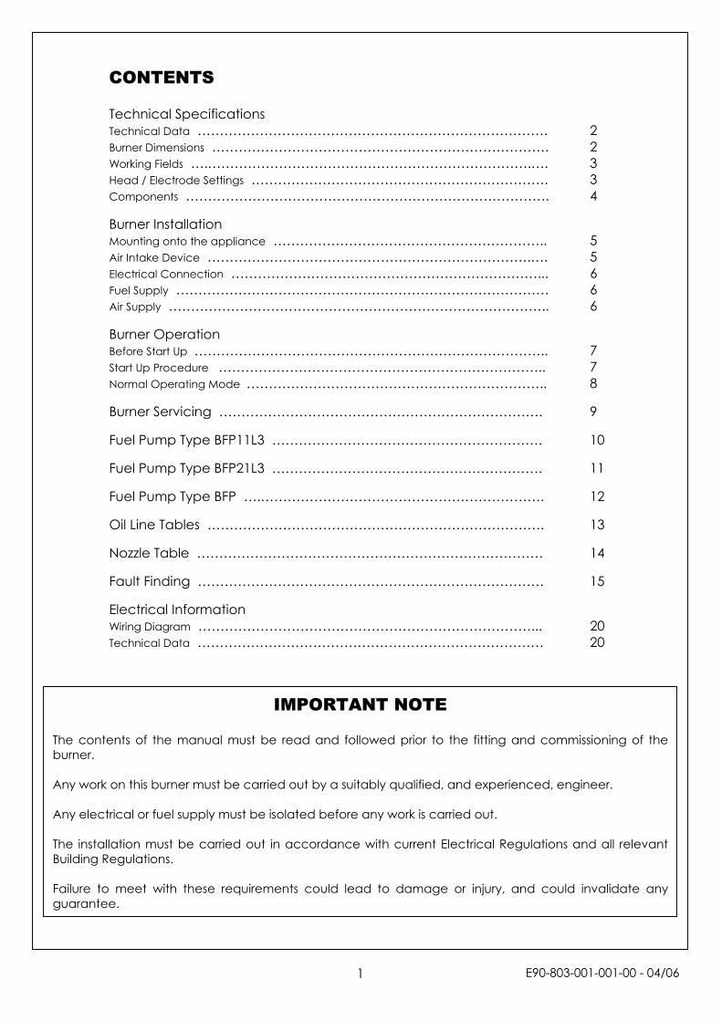
CONTENTS Technical Specifications Technical Data ……………………………………………………………………. 2 Burner Dimensions …………………………………………………………………. 2 Working Fields ….……………………………………………………………….…. 3 Head / Electrode Settings …………………………………………………………. 3 Components ………………………………………………………………………. 4 Burner Installation Mounting onto the appliance …………………………………………………….. 5 Air Intake Device ……………………………………………………………….…. 5 Electrical Connection ……………………………………………………………... 6 Fuel Supply ………………………………………………………………………… 6 Air Supply ………………………………………………………………………….. 6 Burner Operation Before Start Up …………………………………………………………………….. 7 Start Up Procedure ……………………………………………………………….. 7 Normal Operating Mode ………………………………………………………….. 8 Burner Servicing ………………………………………………………………. 9 Fuel Pump Type BFP11L3 ……………………………………………………. 10 Fuel Pump Type BFP21L3 ……………………………………………………. 11 Fuel Pump Type BFP ….………………………………………………………. 12 Oil Line Tables …………………………………………………………………. 13 Nozzle Table …………………………………………………………………… 14 Fault Finding …………………………………………………………………… 15 Electrical Information Wiring Diagram …………………………………………………………………... 20 Technical Data …………………………………………………………………… 20
The contents of the manual must bburner. Any work on this burner must be carr Any electrical or fuel supply must be The installation must be carried out Building Regulations. Failure to meet with these requiremguarantee.
IMPORTANT NOTE
e read and followed prior to the fitting and commissioning of the
ied out by a suitably qualified, and experienced, engineer.
isolated before any work is carried out.
in accordance with current Electrical Regulations and all relevant
ents could lead to damage or injury, and could invalidate any
E90-803-001-001-00 - 04/06
1
TECHNICAL SPECIFICATIONS Technical Data Model X400 X500 X600 Burner output Min kW 14 30 58 Max kW 50 70 130 Fuel Flow rate Min Kg/h 1.2 2.5 4.8 Max Kg/h 4.2 5.8 10.8 Fuel Kerosene Gas Oil
Max viscosity 5.5cst @ 20ºC
Electrical supply V 230V ±10% 50Hz 1 phase Motor W 90 90 130 Transformer 40mA (rms) 15kV Current Start A 1.60 1.60 2.20 Run A 0.53 0.53 0.87 Weight kg 9.2 9.2 9.5 Mode of operation On/off Burner Dimensions (mm)
MX
X
X
X
X
X
X
X
odel AØ
root AØ max B* C D E F G H J K L
400-1N 89 89 73 231 50 161 194 138 268 90 125-150 10
400-2N 89 89 73 231 50 161 194 138 268 90 125-150 10
400-1 89 89 73 231 50 161 194 138 297 90 125-150 10
400-2 89 89 73 231 50 161 194 138 297 90 125-150 10
500-1 89 89 73 231 50 161 204 204 318 90 125-150 10
500-2 89 89 80 231 50 161 204 204 318 90 125-150 10
600-1 89 89 80 231 50 161 204 204 360 90 125-150 10
600-2 89 109 120 231 50 161 204 204 360 90 125-150 10
*Standard lengths only - other lengths are available.
E90-803-001-001-00 - 02/06
2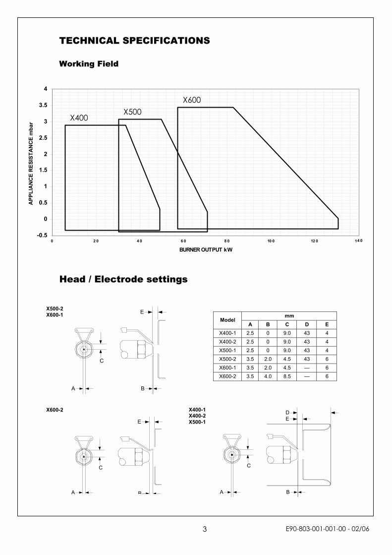
TECHNICAL SPECIFICATIONS
Working Field
-0.5
0
0.5
1
1.5
2
2.5
3
3.5
4
0 2 0 4 0 6 0 8 0 10 0 12 0 1
BURNER OUTPUT kW
APP
LIA
NC
E R
ESIS
TAN
CE
mba
r
BA
C
E
D
X600 X500
X400
4 0
Head / Electrode settings
X500-2
X600-1 mm Model
A B C D E X400-1 2.5 0 9.0 43 4 X400-2 2.5 0 9.0 43 4 X500-1 2.5 0 9.0 43 4 X500-2 3.5 2.0 4.5 43 6 X600-1 3.5 2.0 4.5 — 6 X600-2 3.5 4.0 8.5 — 6
X400-1 X600-2
BA
C
EX400-2 X500-1
3
BA
C
E
E90-803-001-001-00 - 02/06
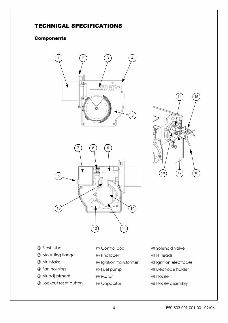
TECHNICAL SPECIFICATIONS Components
1
18 17 16
1514
13
12 11
10
987
6
5
432
① Blast tube ② Mounting flange
③ Air intake
④ Fan housing
⑤ Air adjustment
⑥ Lockout reset button
⑦ Control box ⑧ Photocell
⑨ Ignition transformer
⑩ Fuel pump
⑪ Motor
⑫ Capacitor
⑬ Solenoid valve ⑭ HT leads
⑮ Ignition electrodes
⑯ Electrode holder
⑰ Nozzle
⑱ Nozzle assembly
E90-803-001-001-00 - 02/06
4
BURNER INSTALLATION Mounting onto the appliance The burner is mounted onto the appliance by means of a removable 6-bolt flange. The gasket needs to be put in place before the flange is fixed onto the appliance. The burner tube is then inserted through the centre hole. With the burner rotated a few degrees clockwise the flange bolts will pass through the locating holes. When the burner is twisted into position the top bolt can then be tightened to secure the burner. If necessary the lower screw can be adjusted to give a more secure fixing. If required the burner can be mounted in any position. It is important though to ensure that the solenoid valve on the oil pump is not inclined below horizontal. Air Intake Device
The burner is supplied with an air intake device that can be rotated through 180º to allow the air to be taken from a position suitable within the appliance housing. The intake has a 60mm diameter entry to allow a snorkel tube, as used on some balanced flue units, to be connected. There is a grill fitted to the entry that can be removed if required.
Top locating hole
Bottom locating cut-out
apter
Tube Ad An intake adapter isavailable forapplications equipped with70mm diameter airtubes. For the part numbersee pages 10 and 11for details.
E90-803-001-001-00 - 02/065
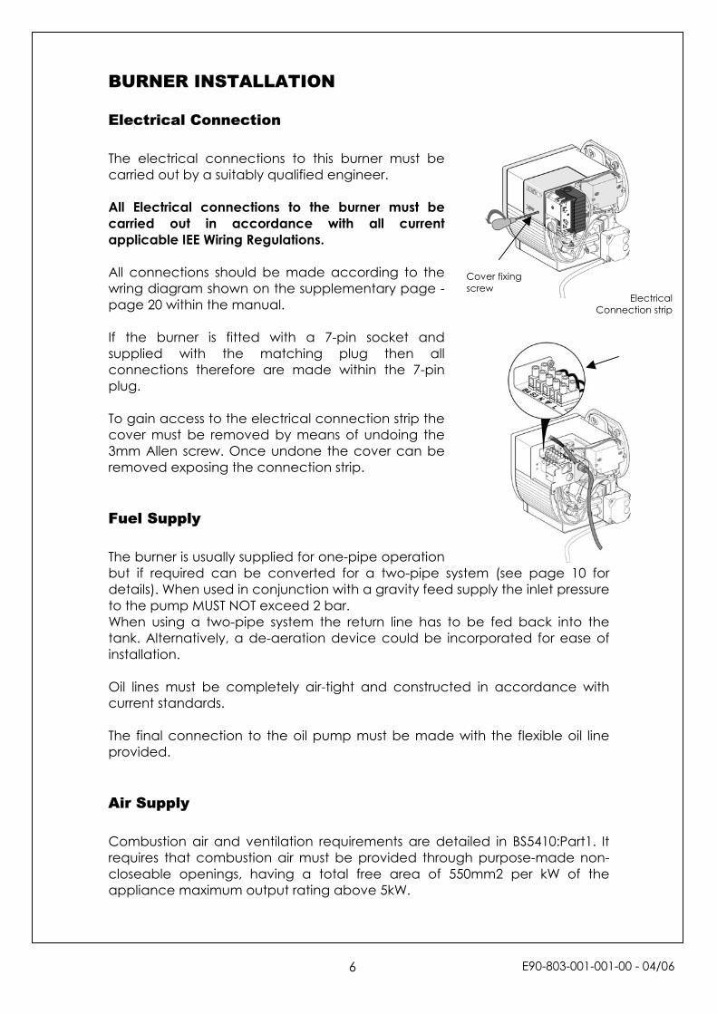
BURNER INSTALLATION Electrical Connection The electrical connections to this burner must be carried out by a suitably qualified engineer. All Electrical connections to the burner must be carried out in accordance with all current applicable IEE Wiring Regulations. All connections should be made according to the wring diagram shown on the supplementary page - page 20 within the manual. If the burner is fitted with a 7-pin socket and supplied with the matching plug then all connections therefore are made within the 7-pin plug. To gain access to the electrical connection strip the cover must be removed by means of undoing the 3mm Allen screw. Once undone the cover can be removed exposing the connection strip.
Fuel Supply The burner is usually supplied for one-pipe operation but if required can be converted for a two-pipe systdetails). When used in conjunction with a gravity feed suto the pump MUST NOT exceed 2 bar. When using a two-pipe system the return line has to tank. Alternatively, a de-aeration device could be incoinstallation. Oil lines must be completely air-tight and constructedcurrent standards. The final connection to the oil pump must be made wprovided. Air Supply Combustion air and ventilation requirements are detarequires that combustion air must be provided throughcloseable openings, having a total free area of 550appliance maximum output rating above 5kW.
Cs
over fixing crew
em (see page 10 for pply the inlet pressure
be fed back into the rporated for ease of
in accordance with
ith the flexible oil line
iled in BS5410:Part1. It purpose-made non-mm2 per kW of the
ElectricalConnection strip
E90-803-001-001-00 - 04/06
6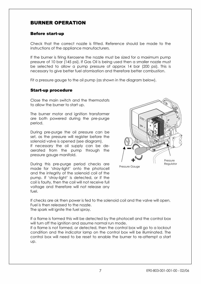
BURNER OPERATION Before start-up Check that the correct nozzle is fitted. Reference should be made to the instructions of the appliance manufacturers. If the burner is firing Kerosene the nozzle must be sized for a maximum pump pressure of 10 bar (145 psi). If Gas Oil is being used then a smaller nozzle must be selected to allow a pump pressure of approx 14 bar (200 psi). This is necessary to give better fuel atomisation and therefore better combustion. Fit a pressure gauge to the oil pump (as shown in the diagram below). Start-up procedure Close the main switch and the thermostats to allow the burner to start up. The burner motor and ignition transformer are both powered during the pre-purge period. During pre-purge the oil pressure can be set, as the pressure will register before the solenoid valve is opened (see diagram). If necessary the oil supply can be de-aerated from the pump through the pressure gauge manifold. During this pre-purge period checks are made for ‘stray-light’ onto the photocell and the integrity of the solenoid coil of the pump. If ‘stray-light’ is detected, or if the coil is faulty, then the coil will not receive full voltage and therefore will not release any fuel. If checks are ok then power is fed to the solenoid coil and the valve will open. Fuel is then released to the nozzle. The spark will ignite the fuel spray. If a flame is formed this will be detected by the photocell and the control box will turn off the ignition and assume normal run mode. If a flame is not formed, or detected, then the control box will go to a lockout condition and the indicator lamp on the control box will be illuminated. The control box will need to be reset to enable the burner to re-attempt a start up.
Pressure Gauge
Pressure Regulator
E90-803-001-001-00 - 02/067
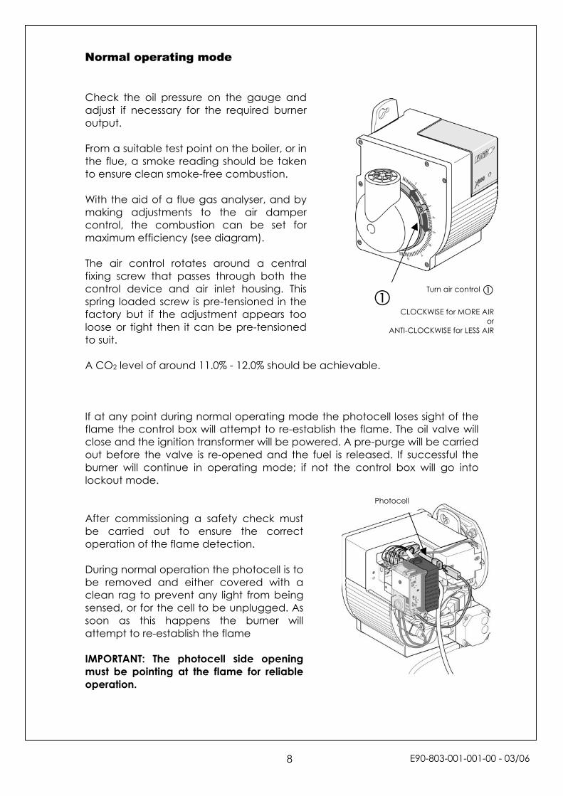
Normal operating mode Check the oil pressure on the gauge and adjust if necessary for the required burner output. From a suitable test point on the boiler, or in the flue, a smoke reading should be taken to ensure clean smoke-free combustion. With the aid of a flue gas analyser, and by making adjustments to the air damper control, the combustion can be set for maximum efficiency (see diagram). The air control rotates around a central fixing screw that passes through both the control device and air inlet housing. This spring loaded screw is pre-tensioned in the factory but if the adjustment appears too loose or tight then it can be pre-tensioned to suit. A CO2 level of around 11.0% - 12.0% should be achievable. If at any point during normal operating mode the photocell loses sight of the flame the control box will attempt to re-establish the flame. The oil valve will close and the ignition transformer will be powered. A pre-purge will be carried out before the valve is re-opened and the fuel is released. If successful the burner will continue in operating mode; if not the control box will go into lockout mode. After commissioning a safety check must be carried out to ensure the correct operation of the flame detection. During normal operation the photocell is to be removed and either covered with a clean rag to prevent any light from being sensed, or for the cell to be unplugged. As soon as this happens the burner will attempt to re-establish the flame IMPORTANT: The photocell side opening must be pointing at the flame for reliable operation.
Turn air control
CLOCKWISE for MORE AIRor
ANTI-CLOCKWISE for LESS AIR
Photocell
E90-803-001-001-00
- 03/06
8
BURNER SERVICING For ease of servicing and access to the burner components the burner has, on the bottom face, a keyhole cut-out. This allows the burner to be hung from the mounting flange in a more convenient position. After loosening the fixing bolt the burner can be extracted from the flange, turned around and then the keyhole can be located onto the bolt. The burner service requires that all of the comchecked for correct operation, or signs of damagout on all safety devices i.e. photocell, solenoid vbe replaced every 12 months, or sooner if worn must be inspected and replaced if necessary. Below are a series of diagrams showing the remocomponents from the burner. This gives access foand the electrodes to be inspected. As shown beis to be removed from the nozzle holder before thprevent any accidental damage.
Once the burner has been re-fitted a smoke chemust be carried out. Once the burner has bappliance and all settings are correct the figures s The burner and all other related equipment must bworking order.
9
ponents are cleaned and e. A check must be carried
alves, etc. The nozzle should or dirty. Filters and fuel lines
val of the combustion head r the nozzle to be replaced low the electrode assembly e nozzle is replaced. This will
ck and combustion analysis een commissioned on the hould then be recorded.
e left in a safe and reliable
E90-803-001-001-00 - 02/06
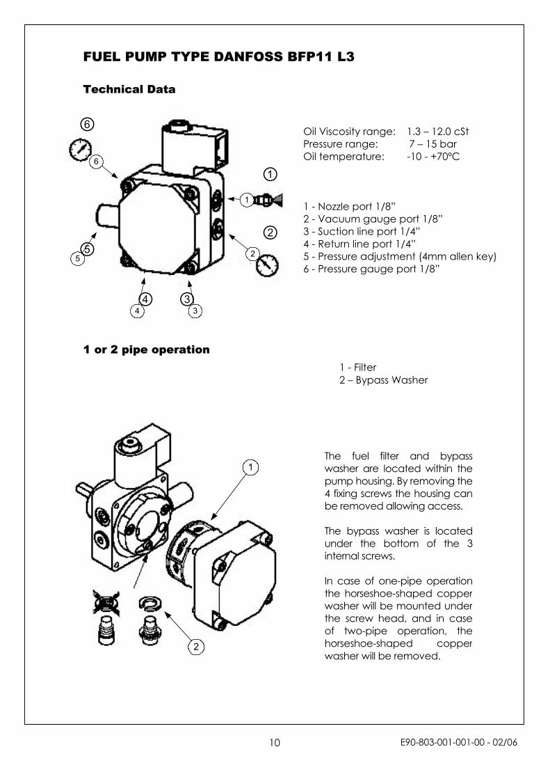
FUEL PUMP TYPE DANFOSS BFP11 L3 Technical Data
1 or 2 pipe operation
1
2
3
6
5
4
2
1
⑥
⑤
①
④ ③
②
Oil Viscosity range: 1.3 – 12.0 cSt Pressure range: 7 – 15 bar Oil temperature: -10 - +70ºC 1 - Nozzle port 1/8” 2 - Vacuum gauge port 1/8” 3 - Suction line port 1/4” 4 - Return line port 1/4” 5 - Pressure adjustment (4mm allen key) 6 - Pressure gauge port 1/8”
The fuel filter and bypasswasher are located within thepump housing. By removing the4 fixing screws the housing canbe removed allowing access. The bypass washer is locatedunder the bottom of the 3internal screws. In case of one-pipe operationthe horseshoe-shaped copperwasher will be mounted underthe screw head, and in caseof two-pipe operation, thehorseshoe-shaped copperwasher will be removed.
1 - Filter 2 – Bypass Washer
E90-803-001-001-00 - 02/06
10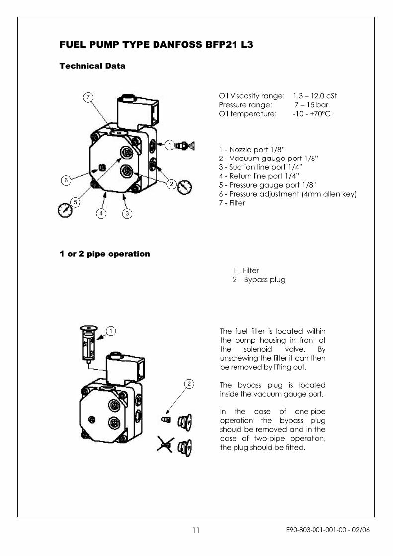
FUEL PUMP TYPE DANFOSS BFP21 L3 Technical Data
1 or 2 pipe operation
1
2
3
6
7
4
5
2
1
Oil Viscosity range: 1.3 – 12.0 cSt Pressure range: 7 – 15 bar Oil temperature: -10 - +70ºC 1 - Nozzle port 1/8” 2 - Vacuum gauge port 1/8” 3 - Suction line port 1/4” 4 - Return line port 1/4” 5 - Pressure gauge port 1/8” 6 - Pressure adjustment (4mm allen key) 7 - Filter
The fuel filter is located withinthe pump housing in front ofthe solenoid valve. Byunscrewing the filter it can thenbe removed by lifting out. The bypass plug is locatedinside the vacuum gauge port. In the case of one-pipeoperation the bypass plugshould be removed and in thecase of two-pipe operation,the plug should be fitted.
1 - Filter 2 – Bypass plug
E90-803-001-001-00 - 02/06
11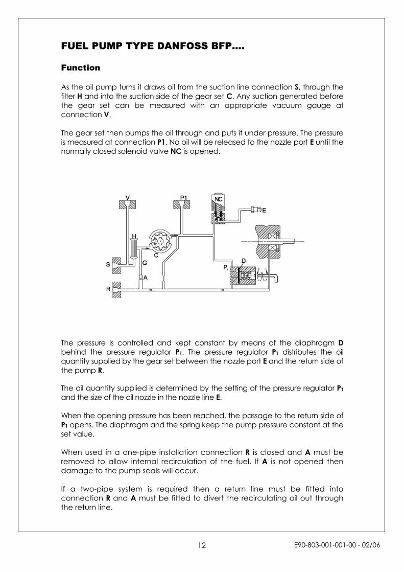
FUEL PUMP TYPE DANFOSS BFP…. Function As the oil pump turns it draws oil from the suction line connection S, through the filter H and into the suction side of the gear set C. Any suction generated before the gear set can be measured with an appropriate vacuum gauge at connection V. The gear set then pumps the oil through and puts it under pressure. The pressure is measured at connection P1. No oil will be released to the nozzle port E until the normally closed solenoid valve NC is opened.
The pressure is controlled and kept constant by means of the diaphragm D behind the pressure regulator P1. The pressure regulator P1 distributes the oil quantity supplied by the gear set between the nozzle port E and the return side of the pump R. The oil quantity supplied is determined by the setting of the pressure regulator P1 and the size of the oil nozzle in the nozzle line E. When the opening pressure has been reached, the passage to the return side of P1 opens. The diaphragm and the spring keep the pump pressure constant at the set value. When used in a one-pipe installation connection R is closed and A must be removed to allow internal recirculation of the fuel. If A is not opened then damage to the pump seals will occur. If a two-pipe system is required then a return line must be fitted into connection R and A must be fitted to divert the recirculating oil out through the return line.
E90-803-001-001-00 - 02/06
12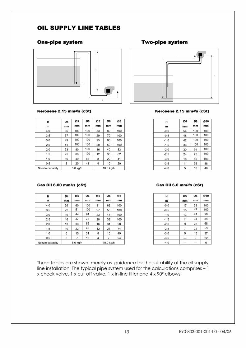
OIL SUPPLY LINE TABLES One-pipe system Two-pipe system
L
Kerosene 2.15 mm2/s (cSt)Gas Oil 6.00 mm2/s (cSt)
These tables are shown merely as guidancline installation. The typical pipe system usex check valve, 1 x cut off valve, 1 x in-line fi
H Ø4 Ø5 Ø6 Ø5 Ø6 Ø8m mm mm mm mm mm mm
4.0 66 100 100 33 80 100 3.5 57 100 100 29 70 100 3.0 49 100 100 25 60 100 2.5 41 100 100 20 50 100 2.0 33 80 100 16 40 83 1.5 25 60 100 12 30 62 1.0 16 40 83 8 20 41 0.5 8 20 41 4 10 20
Nozzle capacity 5.0 kg/h 10.0 kg/h
L
H
H Ø4 Ø5 Ø6 Ø5 Ø6 Ø8m mm mm mm mm mm mm
4.0 26 60 100 31 62 100 3.5 22 51 100 27 55 100 3.0 19 44 94 23 47 100 2.5 16 37 78 20 39 100 2.0 13 30 62 16 31 98 1.5 10 22 47 12 23 74 1.0 6 15 31 8 15 49 0.5 3 7 15 4 7 24
Nozzle capacity 5.0 kg/h 10.0 kg/h
13
Kerosene 2.15 mm2/s (cSt)
Gas Oil 6.0 mm2/s (cSt)
e for the suitability of the oil supply d for the calculations comprises – 1 lter and 4 x 90º elbows
H
H Ø6 Ø8 Ø10m mm mm mm
-0.0 17 53 100 -0.5 15 47 100
-1.0 13 41 99
-1.5 11 34 84
-2.0 9 28 68
-2.5 7 22 53
-3.0 5 15 37 -3.5 — 9 22 -4.0 — — 6
H Ø6 Ø8 Ø10m mm mm mm
-0.0 54 100 100 -0.5 48 100 100
-1.0 42 100 100
-1.5 36 100 100
-2.0 30 94 100
-2.5 24 75 100
-3.0 18 55 100 -3.5 11 36 88 -4.0 5 16 40
E90-803-001-001-00 - 04/06
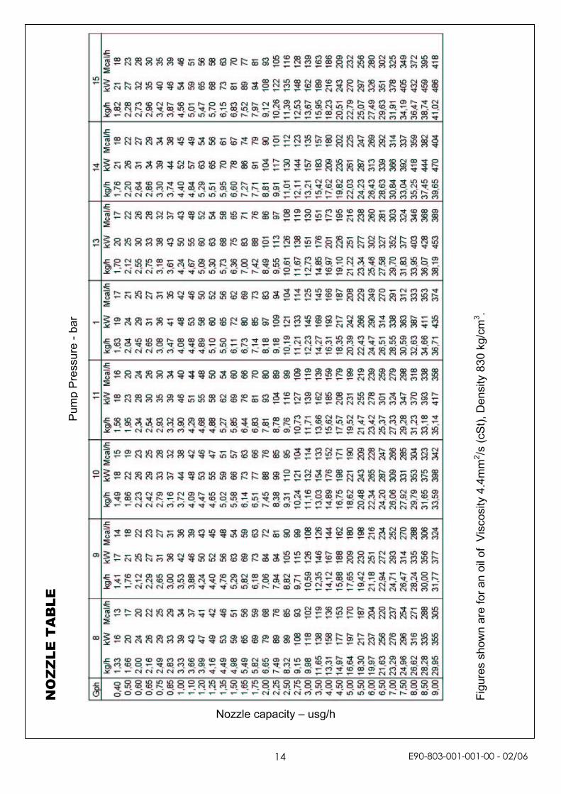
Nozzle capacity – usg/h
Figu
res
show
n ar
e fo
r an
oil o
f V
isco
sity
4.4
mm
2 /s (c
St),
Den
sity
830
kg/
cm3 .
Pum
p P
ress
ure
- bar
NO
ZZ
LE T
AB
LE
E90-803-001-001-00 - 02/06
14
FAULT FINDING Below is a list of some scenarios that may lead to a failure causing the burner to go into lockout mode. There are also some relevant tests and solutions to hopefully overcome any problem that may occur. Push the reset button to re-start the burner. If the burner then functions correctly the control has simply responded to a temporary fault. If the burner still fails then a further investigation will be required to correct any fault.
Fault Probable cause Useful Test Solution
The burner will not start 1) Lack of voltage. 1) If there is 240V onto terminal 9 of the control box but it is not responding then the box is at fault.
2) If there is no voltage onto terminal 9 then there is an external fault.
1) Replace control box. 2) Check any thermostats,
switches, fuses, etc to trace fault.
The burner starts but no flame is present and the burner goes to lockout
1) No fuel to burner. 2) No fuel to the nozzle.
a) No voltage to solenoid coil
b) Voltage to coil but not energizing.
c) Coil energized but no oil at pump outlet.
d) Oil at pump outlet but none through the nozzle.
3) No spark
1) Check if there is oil present at the pump inlet
2)
a) i) Cover photocell. If burner fires up ok then photocell must be detecting a light source during pre-purge.
ii) If there is still no flame disconnect photocell. If now ok then cell must be faulty.
3) Check electrodes, HT leads and voltage to igniter. If all ok then igniter is faulty.
1) Check fuel tank, valves, etc for problems. 2)
a) i) Identify source, spark, etc and remedy.
ii) Replace photocell
b) Replace coil.
c) Check valve opening. Replace if necessary.
d) Replace nozzle, or check line for blockage.
3) Replace igniter.
The burner starts, a flame is established but the burner goes to lockout
1) Check burner wiring. 2) Flame recognition.
2) Expose photocell to
good ambient (or torch) light. a) If the problem
disappears then the problem is with the flame picture
b) If the problem does not disappear then the photocell must be at fault
1) Remedy wiring connections.
2)
a) Reset combustion.
b) Replace photocell.
E90-803-001-001-00 - 02/06
15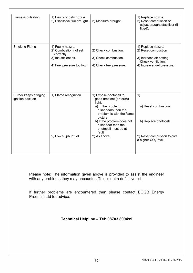
Flame is pulsating 1) Faulty or dirty nozzle 2) Excessive flue draught.
2) Measure draught.
1) Replace nozzle. 2) Reset combustion or
adjust draught stabilizer (if fitted).
Smoking Flame 1) Faulty nozzle. 2) Combustion not set
correctly. 3) Insufficient air. 4) Fuel pressure too low
2) Check combustion. 3) Check combustion. 4) Check fuel pressure.
1) Replace nozzle. 2) Reset combustion 3) Increase air setting.
Check ventilation. 4) Increase fuel pressure.
Burner keeps bringing ignition back on
1) Flame recognition. 2) Low sulphur fuel.
1) Expose photocell to good ambient (or torch) light. a) If the problem
disappears then the problem is with the flame picture
b) If the problem does not disappear then the photocell must be at fault
2) As above.
1)
a) Reset combustion.
b) Replace photocell. 2) Reset combustion to give a higher CO2 level.
Please note: The information given above is provided to assist the engineer with any problems they may encounter. This is not a definitive list. If further problems are encountered then please contact EOGB Energy Products Ltd for advice.
Technical Helpline – Tel: 08703 899499
E90-803-001-001-00 - 02/06
16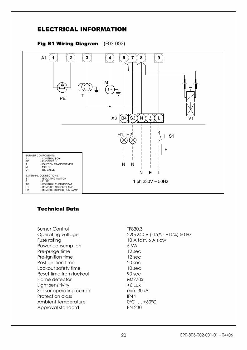
ELECTRICAL INFORMATION Fig B1 Wiring Diagram – (E03-002)
A1 1 2 5 83 974
1 ~
X3 V1
M
TPE
EN L
1 ph 230V ~ 50Hz
N N
F
H2H1 S1
LNS3B4
BURNER COMPONENTS A1 - CONTROL BOX PE - PHOTOCELL T - IGNITION TRANSFORMER M - MOTOR V1 - OIL VALVE EXTERNAL CONNECTIONS S1 - ISOLATING SWITCH F - FUSE TC - CONTROL THERMOSTAT H1 - REMOTE LOCKOUT LAMP H2 - REMOTE BURNER RUN LAMP
Technical Data Burner Control TF830.3 Operating voltage 220/240 V (-15% - +10%) 50 Hz Fuse rating 10 A fast, 6 A slow Power consumption 5 VA Pre-purge time 12 sec Pre-ignition time 12 sec Post ignition time 20 sec Lockout safety time 10 sec Reset time from lockout 90 sec Flame detector MZ770S Light sensitivity >6 Lux Sensor operating current min. 30µA Protection class IP44 Ambient temperature 0ºC …. +60ºC Approval standard EN 230
E90-803-002-001-01 - 04/0620

E90-803-001-001-00 - 02/06

EOGB Energy Products Ltd 5 Howard Road, Eaton Socon, St Neots, Cambs, PE19 8ET
Telephone: 08703 899499 Facsimile: 01480 477022
Website: www.eogb.co.uk E-mail: [email protected]
E90-803-001-001-00 - 02/06