
users instruction manual users instruction manual users instruction ...

IM-280001-2019
Instruction Manual
Eddy-Current Press Drives Models 37-21 49-63
7900 Durand Avenue, Building 3 Sturtevant, Wisconsin, U.S.A. 53177 Tel: 262-554-7977 Fax: 262-554-7041 Toll Free: 800-548-2169 E-Mail: [email protected]

2
Motor control equipment and electronic controllers are connected to hazardous line voltage. When servicing drives and electronic controllers, there may be exposed components with their cases and protrusions at or above line potential. Extreme care should be taken to protect against shock. Stand on an insulating pad and make it a habit to use only one hand when checking components. Always work with another person in case an emergency occurs. Disconnect power whenever possible to check controllers or to perform maintenance. Be sure equipment is properly grounded. Wear safety glasses whenever working on an electronic controller or electrical rotating equipment.
CAUTION: Rotating shafts and above ground electrical potentials can be hazardous. Therefore, it is strongly recommended that all
electrical work conform to National Electrical Codes and local regulations. Installation, alignment and maintenance should be performed only by qualified personnel.
Factory recommended test procedures, included in the instruction manual, should be followed. Always disconnect electrical power before working on the unit.
REFER TO OSHA RULES AND REGULATIONS, PARAGRAPH 1910.219 FOR GUARDS ON MECHANICAL POWER TRANSMISSION APPARATUS. Note Since improvements are continually being made to available equipment, the enclosed data is subject to change without notice. Any drawings are for reference only, unless certified. For additional information contact your nearest Eddy Current representative listed in the Yellow pages under "Power Transmission Equipment". Or write: Drive Source International, Inc. 7900 Durand Avenue Sturtevant WI 53177
IMPORTANT NOTICE
The printed contents in this manual are to be used for reference only. Due to periodic engineering design changes and the addition of modifications, this material is provided as a guide only.
Refer to the enclosed engineering drawings, which are furnished for your specific unit.
For additional information regarding contents, send your request to one of the following departments:
Instruction Material ................................................................... Publications Department Operational Functions .............................................................. Field Service Department Parts ...................................................................................... Renewal Parts Department
This notice is provided to clarify the intent of the instruction book contents and to inform our customers how to obtain appropriate technical assistance from the proper source.
©Copyright DYNAMATIC ,2019
DANGER HIGH VOLTAGE

3
Contents C.E.S. Mechanical Press Drive Introduction ................................................................................................................. 4
Description and Numbering System .............................................................................................................................. 5 Construction of “Package Press Drive” ......................................................................................................................... 5
The Clutch Field and Belt Assembly ............................................................................................................................. 5 Typical Press Drive Mechanical Unit Figure 2 ........................................................................................................ 6
Typical Press Drive Cutaway (37-42 or 49-42) Figure 3 ............................................................................................. 8 Eddy Current Principle .................................................................................................................................................. 9
Relationship of the Mechanical Unit to Electrical Controller ........................................................................................ 9 Mechanical unit energy transference ........................................................................................................................ 9 Tach Generator Assembly; Refer to figures 4, 5, or 6 ............................................................................................ 10
Field Coil Assemblies for Clutch and Brake; Refer to figures 4, 5, or 6 ................................................................ 10 Press Drive Assembly 37-42 Figure 4 ................................................................................................................... 11
Press Drive Assembly 49-42 Figure 5 ................................................................................................................... 12 Press Drive Assembly 49-63 Figure 6 ................................................................................................................... 13
Preventive Maintenance .............................................................................................................................................. 14 Lubrication requirements; Refer to figures 4, 5, 6, & 7 .......................................................................................... 14
Clutch and Brake End Oil Drains ........................................................................................................................... 14 Typical Oil Piping Layout for Bearing Lubrication Figure 7 ................................................................................ 15
Slip Ring and Brush Assembly .................................................................................................................................... 16 Eddy Current Coupling Figure 8 ............................................................................................................................. 17
Ventilation .............................................................................................................................................................. 18 Pedestal Bearing Driver Bearing Cap (Brake End) Figure 9 .................................................................................. 18
Pedestal Bearing Driver Bearing Cap (Clutch End) Figure 10 ............................................................................... 18 Belts ............................................................................................................................................................................. 19
Inspection of Flywheel Brake Shoes ........................................................................................................................... 19 Minimum Brake Shoe Wear Table 1 ...................................................................................................................... 20
Safety Guard Figure 11 ........................................................................................................................................... 20 Troubleshooting ........................................................................................................................................................... 20
Bearings .................................................................................................................................................................. 20 Vibration ................................................................................................................................................................. 21
Press Drive Pedestal (Showing Four positions of Oil Drain Outlet)Figure 12.......................... 21
Repair and Minor part Replacement ............................................................................................................................ 21
Brushes ................................................................................................................................................................... 21 Thyrites ................................................................................................................................................................... 22
Installation/Replacement of Belts ........................................................................................................................... 22 Lifting of the Press Drive Mechanical Unit Figure 13 ............................................................................................ 22
Complete Mechanical Unit Change-out ...................................................................................................................... 23

4
C.E.S. Mechanical Press Drive Introduction The C.E.S. (Constant Energy System) controller and eddy current mechanical drive unit are applied in stamping press applications to provide the starting torque and braking action that are required without the need for physical contact between the drive shaft and the crankshaft, or the crankshaft and the holding brake until after the slide velocity is almost completely at rest. This eliminates the periodic replacement of clutch pads by removing the air actuated clutch and only utilizing the holding brake to stop movement at low slide velocity and hold slide position. The largest advantage is in regard to ability to slow the slide velocity during the cycle by reducing the clutch action and using the eddy current brake portion of the mechanical unit to slow the slide to the desired working speed. At this point the braking action stops and the clutch portion provides the necessary driving torque through the material. If required, upon exiting or passing the bottom of the stroke, the clutch portion could accelerate the slide to a higher rate of speed or the same rate as during the initial start of the cycle. This flexibility within the system allows for an overall greater number of parts per hour by means of a higher average rate of strokes per minute. The unique advantages of the eddy current press drives are:
1. Does not require a friction clutch 2. Can provide slow down during cycle 3. Higher production rates with slow down during drawing process 4. Soft starting and stopping of press crankshaft

5
Description and Numbering System The mechanical unit is comprised of four primary parts that make up the complete unit. The clutch field and flywheel assembly, the rotor and output shaft, the brake coil assembly, and the bearings and support structure. The physical size of the unit is identified with a series, of numbers which refer to the diameter of the inner rotor assembly and the number of clutch and brake coils mounted within the package press drive. An example of this would be 49-63 and 49-42. In each case, there is a 49-inch drum (rotor assembly), and either 6 or 4 clutch coils and 3 or 2 brake coils.
Construction of “Package Press Drive” The support structure or pedestal is of pedestal is of fabricated steel construction which is bolted to the sole plate. The straight through drive shaft is supported by spherical roller bearing at each end of the shaft.
The Clutch Field and Belt Assembly This portion of the mechanical unit is mounted on bearings on the output shaft of the press drive and is driven with belts by the motor. The field coil assembly is enclosed within the outer flywheel by a number of pole faces to firm an electromagnet. Energy is supplied to the clutch coils through three slip ring assemblies and brushes. Because of the designed weight and mass, the flywheel and clutch coil assembly stores a large amount of kinetic energy which may be transferred to the output shaft. The ability to store energy in this assembly creates a flywheel effect which may be tapped into at any time by providing clutch coil current and transferring that energy through the rotor assembly to the output shaft and to the press crankshaft. The outboard end of the flywheel assembly is supported by a single roller bearing. This allows the flywheel and field assembly to rotate on the output shaft independently with regard to the rotation of the output shaft. On the inboard side of the belt ring assembly, there is a double spherical roller bearing which supports the belt ring and offsets thrust in a lateral direction by incorporation opposingly angled rollers to eliminate deflection in any direction. The brake coil field assembly is the stationary member of the unit. It is bolted directly to output pedestal. The brake field can contain from 1 to 3 separate field coils. This assembly is used to apply braking torque to the brake rotor when slowing or stopping the slide velocity.

6
Typical Press Drive Mechanical Unit Figure 2

7
The clutch and brake rotor assemblies are both constructed of fabricated steel with smooth segmented outer surfaces. There are two separate assemblies which are keyed to the output shaft. The clutch and brake rotor assemblies are located within the respective fields with only an air gap between the pole faces and the rotor surfaces to separate them. This air gap allows for air to flow across the pole faces for cooling purposes and created an area where the eddy current field is established allowing for torque transference without any mechanical interaction. Since the drive shaft can be accelerated and decelerated for each press ram cycle, the weight has been minimized to curtail high inertia and reduce acceleration and braking energy requirements. Both rotors rotate at the same speed by being keyed to the output shaft. Clutch current to the mechanical unit provides the accelerating torque and current supplied to the brake coils provides braking action, but not to a compete stop. For both the clutch and brake fields to create torque, there is a minimum amount of slip or rotation that is required. This is why the output speed of the mechanical unit will never match the speed of the flywheel assembly of the brake assembly will not completely stop the press because of the need for movement (slip) to cut the electromagnet field that is created by the filed assemblies. WARNING! THE EDDY CURRENT BRAKE CANNOT BE USED AS A HOLDING BRAKE. Safety laws require that a mechanical holding brake be installed on all press drives to hold the press ram stationary until the succeeding ram cycle has begun. The braking capacity of this mechanical brake must be sufficient to bring the press drive shaft to a complete stop in the event of a loss of electrical power or eddy current brake failure. Attached to the belt ring and clutch field assembly is a slip ring assembly. It consists of three bronze rings mounted in insulating material. Since the clutch coils are physically and electrically connected to the slip rings, they rotate together. Power to the clutch coils is carried through these slip rings from brushes mounted inside the clutch pedestal. The brushes, eight for each slip ring, are positioned on opposing sides of the slip ring to ensure uninterrupted brush-to-ring contact during periods of vibration

8
Typical Press Drive Cutaway (37-42 or 49-42) Figure 3

9
Eddy Current Principle The eddy current principle is used by the press drive clutch to accelerate the press drive shaft and transmit power from the clutch flywheel (belt ring assembly) to the press ram. The clutch filed and rotor have no physical contact between them, except for the two support bearings. The eddy current principle also is used in the brake section to decelerate the output shat, which in turn transmits braking torque to the press crankshaft. Drive motor rotation is coupled to the press ram through the electromagnetic field in the eddy current clutch. The drive motor is not stopped or started for each ram cycle, thus allowing for continuous motor operation during press operation. The only parts that are subject to wear are the bearings, brushes, and slip rings. Providing a dc current through either the clutch or brake coils of the mechanical unit produces an electromagnetic field within the air gap between the field assembly and the rotor assembly. As the rotor surface cuts this field, it produces attraction to the mechanism producing the field. If this happened to be the flywheel assembly in which the clutch coils are mounted, the rotor will attempt to catch up to the rotating field until the necessary speed that is requested in met. At this point, the dc current will be shut off and the attraction will stop. If the dc current is applied to the brake field assembly, the electromagnetic field will provide torque to the rotor in the brake section. The brake field assembly is mounted to the output pedestal and is stationary. The eddy current field provides a braking torque to the already turning rotor and will provide stopping torque. It should be noted that the amount of torque produced in either the clutch or the brake portion of the mechanical unit is a function of the amount of excitation current presented to the coil assemblies and the amount of slip between the electromagnetic field and the attracted rotor. For this reason, the output shaft of the mechanical unit will never rotate at the same speed as the flywheel assembly. Also, the brake section will not provide complete stopping torque or holding torque because of the low speed (rpm) of the rotor and its inability to cut sufficient lines of the electromagnetic field.
Relationship of the Mechanical Unit to Electrical Controller Mechanical unit energy transference The C.E.S. controller provides the voltage and current to the mechanical portion of the press drive package for regulating the ram velocity. The current for the clutch section is transferred to the brush and slip ring assembly to excite the field coils to provide rotating torque. The brake

10
assembly is fixed in position, so there is no need for a set of slip rings; and the output from the controller is directly connected to the brake coil assembly. In the beginning of a stroke, the C.E.S. controller will force current into the clutch coil. This will apply magnetic attraction from the already rotating field coil and flywheel assembly to the stationary rotor assembly which is attached to the output shaft. As the press velocity becomes equal to the required speed, the clutch coil field will be reduced, and rotational torque will be reduced, as the speed increases above the desired set point, the brake field coil assembly will be energized to provide baking torque to bring the speed back to the desired operating range., this type of operation between the clutch and brake circuit is referred to as a “Mutuatrol” operation. Tach Generator Assembly; Refer to figures 4, 5, or 6 The tach generator assembly is located on the clutch input end of the mechanical unit. Since the eddy current clutch is a torque transmitter, it has no inherent speed sense. The tach generator field assembly is located around the input end of the drive shaft to provide a velocity feedback to the controller. The tach field assembly is assembled in a special housing that provides an end cap for the output shaft pedestal bearing. The fields surround the output shaft. Seated on the output shaft is a magnet that rotates with shaft movement. This assembly, as depicted on the assembly drawing, is pinned to the shaft every 120 degrees around the shaft circumference for each assembly. The field windings in the assembled housing are oriented so that they are 90 degrees apart in regard to phase of the output waveforms. In this particular application, only one set of the two field windings is used for feedback and the other is a spare set usually marked G5 and G6, with the main set being labeled G1 and G2. Field Coil Assemblies for Clutch and Brake; Refer to figures 4, 5, or 6 The clutch coils that are inside the flywheel are pressed into the outer belt ring housing. Each coil is situated so that it is in series aiding, and the coils must be marked and installed in the same fashion. The brake coils are mounted in the brake and ring assembly and must be installed in a series aiding configuration. The flywheel assembly is then mounted to the pedestal at the output shaft end.

11
Press Drive Assembly 37-42 Figure 4

12
Press Drive Assembly 49-42 Figure 5

13
Press Drive Assembly 49-63 Figure 6

14
Preventive Maintenance Lubrication requirements; Refer to figures 4, 5, 6, & 7 Lubrication is supplied to the four bearings by a forced oil system. This system may either be tied in with the press lube system or by a separate closed system. The outlet of either type of system is tied into a main inlet block. The two end bearings that are mounted in the pedestal are fed by individual lines. The oil flows through the bearing by gravity and collects in two galleries for return through separate headers. The two clutch support bearings are lubricated through the input end of the drive shaft. Oil enters through a toto-seal feed assembly to a rifle drilled channel through the center of the shaft to the bearings. Each bearing has its own gallery for oil return to the reservoir through two separate return lines. Typically, the amount of oil for each bearing is 0.85 cu. In. per bearing per minute. The viscosity may be between 1000 to 1600 S.U.S. at 110 to 115 degrees Fahrenheit. Straight mineral type oil containing rust and oxidation inhibitors must be used with the minimum viscosity of 90, flashpoint of 470 degrees Fahrenheit. Oil viscosities that are thicker may not flow properly and cause a starvation condition. If the viscosity is too thin, proper lubrication will not be maintained and bearing failure will occur. Also, the bearing seals will no be able to retain the oil, and oil consumption will be considerable. It, therefore, is required that oil guidelines be adhered to for proper oil distribution to the bearings. In order to maintain the proper oil flow, it is necessary to position the oil drains in the pedestal bearing inner caps in the proper position to provide a gravity flow return to the press lube system. Each bearing cap may be placed in any one of four positions. The oil outlet should always be positioned at the lowest position of the cap when installed on the press. Please refer to the Press Drive Pedestal drawing (showing four positions of oil drain outlet). Clutch and Brake End Oil Drains If the oil drain are not in their proper position, remove the shaft end guard from the pedestal bearing outer cap on the clutch end of the press drive. Remove the pedestal bearing outer cap from the brush ring assembly on the clutch end. Remove the four socket head screws that secure the pedestal bearing inner cap to the pedestal. Refer to Pedestal Bearing Cap (Clutch End) drawing. Rotate the bearing inner cap carefully to its proper position and install the four socket head screws and reassemble the outer bearing cap and shaft cover. The brake end bearing may be changed in the same manner with the exception of the shaft end guard. Refer to pedestal bearing inner cap (brake end) drawing. By shifting these oil drains, it will allow the press drive to be mounted in various positions to facilitate mounting restrictions and still maintain a gravity flow for oil return to the sump.

15
ALL AIR-COOLED PRESS DRIVES HAVE SIMILAR PIPING LAYOUTS C36034
Typical Oil Piping Layout for Bearing Lubrication Figure 7
Item No. Description
'I Main oil system connector 2 Hose 3 Copper coated steel tubing
(Normal output end) 4 Copper coated steel tubing
(Oiler end) 5 Hose
• • '
SHAFT BEARING INLET THRU
BEARING CAP
CLUTCH BEARING BRAKE END
SHAFT BEARING INLET THRU
BEARING CAP
DUAL SWIVEL OIL FEED TO
CLUTCH BEARINGS
NORMAL OUTPUT END
OILER END
N ‘ \
CLUTCH BEARING FRONT END
1/4 N.P.T. — 4 HOLES TO CONNECT SECONDARY SECONDARY OIL LINES
OIL LINES FROM MAIN FEEDER

16
Slip Ring and Brush Assembly It is important that the slip rings and brushes be periodically inspected to prevent uninterrupted press operation.
1. Keep slip rings and brushes free of dirt, grease, oil and ay foreign particles or contaminants.
2. Clean slip rings and adjacent surfaces with compressed air and approved cleaning solvents. Buff slip rings periodically with a fine, nonconductive abrasive cloth or paper to ensure god electrical contact with brushes.
3. If the brush contact surfaces become pitted from electrical arcing or contact with abrasive materials, it will be necessary to polish the rings, using any of the accepted procedures. This should also be done if for some reason the rings become out of round, causing the brushes to jump off the slip rings during each revolution, breaking the electrical contact or at least causing severe arcing.
4. After polishing the slip rings, all metal particles should be removed from the slip ring area. 5. All brushes should be removed to check their slip ring contact area. 6. If the curvature is not correct for full contact, polish with sandpaper to maintain good
current transfer without arcing. Do not use Carborundum paper. 7. Before the brushes become short and start to bind in the holder, they should be replaced. 8. Quarterly inspection of the slip rings and brushes should be performed as part of
preventive maintenance.

17
Eddy Current Coupling Figure 8
18
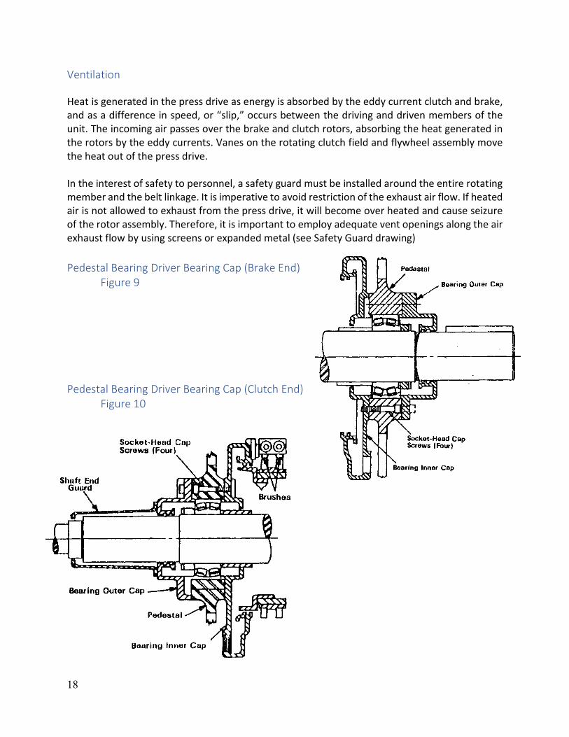
Ventilation Heat is generated in the press drive as energy is absorbed by the eddy current clutch and brake, and as a difference in speed, or “slip,” occurs between the driving and driven members of the unit. The incoming air passes over the brake and clutch rotors, absorbing the heat generated in the rotors by the eddy currents. Vanes on the rotating clutch field and flywheel assembly move the heat out of the press drive. In the interest of safety to personnel, a safety guard must be installed around the entire rotating member and the belt linkage. It is imperative to avoid restriction of the exhaust air flow. If heated air is not allowed to exhaust from the press drive, it will become over heated and cause seizure of the rotor assembly. Therefore, it is important to employ adequate vent openings along the air exhaust flow by using screens or expanded metal (see Safety Guard drawing) Pedestal Bearing Driver Bearing Cap (Brake End) Figure 9 Pedestal Bearing Driver Bearing Cap (Clutch End) Figure 10

19
Belts If the drive belts need to be replaced, replacement may be performed without having to remove the entire mechanical unit from the press.
1. Uncouple the mechanical unit from the press gearing. 2. Remove all the air and lube line connections that are attached to the pedestal running to
and from the oil supply reservoir and flywheel brake cylinders if they will interfere with placement of the belts.
3. Remove all wiring for the clutch and for the tach generator assembly at the junction box on the pedestal.
4. Remove the return oil collection piping for the center support bearing. This would interfere with placement of the belt around the belt ring assembly.
5. Install both tie bard (refer to Figure 13) and tighten to secure the two ends of the pedestal from moving while lifting the mechanical unit off the sole plate. Lifting of the mechanical unit without the tie bars will cause twisting of the pedestals and misalignment of the clutch and brake components.
6. Remove the pedestal centering pin that is located on each corner of the mechanical unit. 7. Remove the anchoring bolt at each corner of the clutch end pedestal. Back the anchor
bolts on the brake end of the pedestal out 1/16” of an inch. 8. If shims are used to align the output shaft with the press shaft make sure they stay in the
proper location. 9. Attach a four-hook sling for the proper weight to the four lifting eyes on each corner of
the end pedestals (refer to figure 13) 10. Lift the mechanical unit high enough to allow the spacer plates between the clutch end
pedestal foot and the sole plate to be removed. 11. Slide the belts under the pedestal and insert spacers, replacing any shims which may have
been removed, and lower unit back into position. Replace centering pins and re-bolt the mechanical unit to sole plate.
12. Remove the lifting sling and remove tie bars on the mechanical unit. 13. Place the v-belts in position over the belt ring assembly and in the grooves. 14. The belts should, at this point, be led out to the motor and the tie bars on the top should
be replaced to support the upper portions of the pedestal during operation. 15. Reconnect the lubrication lines and air lines to the mechanical unit along with the wiring.
The coupling to the press gearing should be installed and belts positioned around the motor sheave and tightened.
Inspection of Flywheel Brake Shoes The flywheel brake shoes are used to stop the rotation of the belt ring assembly when the main motor is stopped. The shoes are made of non-asbestos type material. The wear of these shoes is a function of the number of stops over a period of time. They should be inspected as part of preventive maintenance on a quarterly basis and replaced when the shoes are worn down to the

20
figures in Table 1. Minimum Brake Shoe Wear Table 1 Model No. 37-42 49-42 49-63 Wear 0.50 in. 0.50 in. 0.50 in
Safety Guard Figure 11
Air Exhaust
Troubleshooting Bearings All the bearings incorporated in the eddy current mechanical unit are of the spherical roller variety. The outer pedestal bearings are double roller type with a single roller for the inner support bearing on the clutch end of the mechanical unit. A double spherical bearing is used for the center support bearing. With proper lubrication of the bearings, the wear on these bearings should be minimal for long periods of operation. If the mechanical unit is improperly aligned the offset loading on the bearings will cause premature wear and early failure. Steps should be taken to assure that the mechanical unit has been aligned to the press crankshaft and is level with respect to the sole plate, and within 1 degree.

21
Vibration During the manufacturing process, the eddy current mechanical unit is balanced for minimal vibration. If excessive vibration is noticed during operation, the bearings should be inspected for excessive noise levels. It may also be due to improper alignment with respect to the press crankshaft. Angular misalignment should not exceed 0.005 of an inch between the two shafts. If excessive bearing noise or vibration is noticed, please consult the text covering realignment of the output shaft and leveling of the mechanical unit. Press Drive Pedestal (Showing Four positions of Oil Drain Outlet) Figure 12
Repair and Minor part Replacement Brushes Brushes are the only parts of the systems that are subjected to constant wear. They may need to be replaced on a periodic basis as their length becomes too short to allow proper alignment within the brush holder to the slip ring conducting surface. They may be removed by releasing the retaining spring on the back side of the depression arms. After retracting the arm, the brush will slide out of the slot and the copper braided wire can be loosened and removed from the terminal. Before installing the new brush, the bottom contact surface should be inspected for proper curvature. If the curvature is not proper, it may be changed with a non-carborundum paper to assure for proper current transfer. Place the brush in the holder and reset the retaining spring to the original setting. Terminate the copper braided wire on the corresponding terminal.

22
Thyrites Thyrites assemblies are connected across the clutch coil and slip ring assemblies in order to protect the coil assemblies against high voltage transients. These assemblies should be inspected on a periodic basis to assure that the epoxy has not cracked or blistered, causing contamination. Thyrite assemblies usually consist of three protector plates isolated from each other by thyrite resistor discs. An insulated stud is positioned through the center of the assembly. A locking nut on each end of the stud are wired according to the schematic on your assembly drawing. If replacement is necessary, please refer to the instruction sheet that has been provided at the back of your instruction book. The instruction sheet for thyrite replacements is IS-000071-8100. Installation/Replacement of Belts Periodic inspection of belts should be performed as a part of overall preventive maintenance. The belts may display signs of fatigue, cracks, fraying, or they may have been adjusted to the furthest point of adjustment at the drive motor; then they will have to be replaced. They should always be replaced in sets to eliminate the possibility of having to perform the same task within a short time later. A full description of the procedure of belt change-out is contained in the section covering belts Lifting of the Press Drive Mechanical Unit Figure 13

23
Complete Mechanical Unit Change-out If a failure occurs, it may be a bearing or field coil failure within the mechanical unit. The unit may be changed out by the following procedure:
1. Release the tension to the drive belts by backing off the adjustment screws or bolts at the base of the motor and moving the motor toward the mechanical unit.
2. Remove the belts from the motor sheave 3. Disconnect all wiring to the clutch and brake coil termination points and label them
accordingly. Remove the wiring to the tach generator field assembly and tag the wires accordingly.
4. Disconnect the lubrication lines to the main inlet termination block and remove the oil return lines to the reservoir.
5. Disconnect the airlines to the belt ring and flywheel assembly brake shoe cylinders mounted on the pedestal
6. Install the tie bars on the top and bottom positions on both sides of the pedestal. This will retain the pedestal alignment and eliminate twisting while lifting the unit off the top pf the press.
7. Uncouple the mechanical unit from the press drive shaft at the coupling. 8. Unbolt the sole plate from the press mounting position. 9. Move the crane into position and attach the four-point lifting harness to the lifting eyes. 10. Before lifting, fasten the drive belts to the mechanical unit to eliminate the possibility of
them becoming hooked on press components while moving the unit. 11. At this point, the mechanical unit may be lifted from its mounting on the press. This
should be performed slowly to assure that obstacles are cleared, and any unseen piping or wiring can be removed if it was missed previously.
12. Before placing the new unit on the mounting area, the area should be thoroughly cleared of debris and the actual mounting areas be checked for gouges or scratches that will cause alignment problems.
13. Install the tie bars on the new mechanical unit and secure them in place. The drive belts should be installed on the shop floor; it will be easier there because of the restriction of space on top of the press. The belts may be replaced by unbolting the mechanical unit from the sole plate and lifting the unit up just enough to allow the belts to the slipped under the clutch end of the mechanical unit. Once in position, the sole plate and pedestal may be reconnected. The tie bars may be removed to allow the belts to be placed around the belt ring in their proper position.
14. At this point, the tie bars may be installed and the four-point lifting harness attached so the mechanical unit may be lifted into position on the press.
15. The mechanical unit may be bolted into place 16. It will be necessary to check for angular alignment and run-out between the directly
connected shafts. It will also be necessary to check the pedestal for level within 1 degree of plum at any of the four corners of the pedestal. Please refer to the insert supplied with the instruction book on installation and alignment of eddy current equipment
24
17. After completion of alignment and leveling, all wiring, lubrication and air piping should be installed. The belts may be installed.
18. Before operation, the lubrication system should be started, and the oil flow checked for the proper amount of oil flow to each bearing. The brake and clutch coil wiring should be checked by the electrician for the proper resistance readings according to the prints stating the size and connection configuration. The tach generator wiring should also be checked for proper wiring.
At this point, the mechanical unit is ready to be placed back into service. The press operation should yield the same tonnage and speed as the original unit. There will be no need to make any changes to the C.E.S. press drive controller. Please feel free to address any questions you may have regarding the equipment installed in your facility. These questions may be address to the service department.

25
7900 Durand Avenue, Building 3
Sturtevant, Wisconsin, U.S.A. 53177 Tel: 262-554-7977 Fax: 262-554-7041
Toll Free: 800-548-2169 E-Mail: [email protected]