INSTRUCTION MANUAL Diagonal lift 504 - Mountway · INSTRUCTION MANUAL Diagonal lift 504 ... 9....
20
Diagonal lift Diago 504 Doc. No: M504 Edition: 9 Date: 2014-10-29 INSTRUCTION MANUAL Diagonal lift 504 Granberg Interior AB Box 6112 SE-600 06 Norrköping SWEDEN English
Transcript of INSTRUCTION MANUAL Diagonal lift 504 - Mountway · INSTRUCTION MANUAL Diagonal lift 504 ... 9....

Diagonal lift Diago 504 Doc. No: M504
Edition: 9 Date: 2014-10-29
INSTRUCTION MANUAL Diagonal lift 504
Granberg Interior AB Box 6112SE-600 06 NorrköpingSWEDEN
English

For mer information, see:www.granberg.se

Section: Headline: Page:
1. Introduction ...................................................................................................................................................42. Declaration of Conformity ........................................................................................................................43. Intended use - Technical data ................................................................................................................ 4
Installation instructions:4.1 Mechanical construction ....................................................................................................................... 54.2 Delivery modules ........................................................................................................................................ 54.3 Pre-assembly of the lift mechanism .................................................................................................... 64.4 Joist heights .................................................................................................................................................. 74.5 Location wall socket and control devices ..........................................................................................84.6 Location wall socket for lighting ...........................................................................................................9 4.7 To consider before installation ..............................................................................................................94.8 Installation on a wall ............................................................................................................................... 104.9 Adjustments to get the lift vertical ....................................................................................................104.10 Installation of cabinet on lift mechanism ........................................................................................ 114.11 Installation of light ramp (accessory) ................................................................................................. 124.12 Installation, connection of trip plate.................................................................................................. 124.13 Installation of lighting under the safety panel (accessory) ........................................................ 124.14 Functional test.............................................................................................................................................. 12
Operator’s information:5.1 Safe use .......................................................................................................................................................... 13 5.2 Safety arrangements .................................................................................................................................14 5.3 Load distribution and side forces .........................................................................................................14 5.4 Actions after use ........................................................................................................................................ 14 5.5 Alternative control devices .................................................................................................................... 15 5.6 Cleaning ....................................................................................................................................................... 15 5.7 Maintenance ............................................................................................................................................... 16
6. Instructions for Recycling ...................................................................................................................... 16 7. Decals ............................................................................................................................................................ 16 8. Warranty ....................................................................................................................................................... 17 9. Service & maintenance records ........................................................................................................... 17 10. Fault finding ................................................................................................................................................ 1811. Spare parts list ............................................................................................................................................ 18 12. El. system / Electric circuit diagram .................................................................................................... 19 13. CE-Declaration of Conformity ............................................................................................................... 19
Content

4
2. Declaration of Conformity with EU-directives
This product is CE-marked and is granted to conform to the basic safety and operation requirements, in accordance with de actual Machinery, EMC- and Low voltage Directives. A separate ”CE-Declaration of Conformity” is available in section 13.
3. Intended use - Technical data
The wall cabinet lift series 504 is intended to achieve a convenient location to put or pick of normal kitchen cabinet items, e.g. dry groceries and household objects, by means of manoeuvring the shelf system along an arc-shaped path down to the worktop level below it. The operation shall be indoors, under normal housing conditions regarding temperature, humidity and lighting.
The Diagonal lift is not intended for use in moist environments.
It is assumed that the wall cabinet is made according the standards EN 1116 and EN 1153.
Technical data, Diagonal Lift 504
Model 504-055 (600 - 1100 mm cabinet width)
504-115 (1200 - 1800 mm cabinet width)
Cabinet width 600 - 1100 mm 1200 - 1800 mm
Cabinet height 700 - 1100 mm 700 - 1100 mm
Cabinet depth, max 400 mm 400 mm
Vertical stroke, max 435 mm 435 mm
Horizontal stroke, max 147 mm 147 mm
Time for a lift or lowering stroke, approx. 26 s 26 s
Mains voltage 230 V / 120 V* 230 V / 120 V*
Power consumption 345 W / 324 W* 345 W / 324 W*
Max number of full work cycles/ hour 6 6
Control and lighting voltage 24 V DC 24 V DC
Weight excl. cabinet 22 kg 31 kg
Weight incl cabinet, maximum size 66 kg 115 kg
Max load in the cabinet 95 kg 50 kg
Noise pressure less than 70 db(A) 70 db(A)
1. Introduction
We have the pleasure to deliver a Granberg Interior wall cabinet lift series Diago 504. This is an electrically operated lifting and lowering system for installation of new or existing wall cabinets. It can be used separately, or together with the Granberg work top units, and it becomes then a total adaptation of the kitchen. The lift is suitable for all wall cabinets of various makes, which are made according the standards EN 1116 and EN 1153.
Only authorized persons may use the 504 wall cabinet lift!
Authorization means obligation to read and follow the instructions.
It is very important that you read and understands the instructions before you use the device. If you have any questions - contact your supplier.
This Instruction manual shall be available for all concerned persons, be kept in a protected place and shall follow the product, if it is moved to another installation site or another house or apartment owner.
Correct use, operation, inspections and maintenance are decisive for efficient and safe work.
* The voltage depends on which model that is delivered

5
4.1 Mechanical construction
The diagonal lift Diago 504 comprises a wall frame, to be installed on a wall, a cabinet frame onto which one or more cabinets are installed, and four link arms that operate in parallel. The arc-shaped lift and lowering path is achieved by an electrically pow-ered screw jack, which operates between the wall and cabinet frames.
4.2 Delivery modules
The diagonal lift is delivered in boxes. The components shall be assembled in accordance with the assembly instructions.The packaging material shall be handed over to an organized material re-cycling organisation.
Top and bottom plates with attachment details. The plastic retainers and strips shall be used for fastening the electric cables, once the lift installation work is finished.
Lift mechanism without top and bottom plates.
Trip panel with attachment details. Control box (The box on the picture is used for outside installation).
Lighting and transformer with attachment details. (Accessory)
Top plate
Bottom plate

6
C
A
B
G
E
D
K
E
4.3 Pre-assembly of the lift mechanism 4.3.1 Install the bottom plate (A) onto which the cabinet shall be mounted. The plate is hung on the frame, and then locked with the M5x45 screws (B). (Do not forget the washer).
NOTE! It is very important that the locking screws (B) are installed
4.3.2 Install the top plate (D) on the height adjustable side profiles (E) with the cabinet support downwards.
4.3.3 Lock with the hexagonal screws (K).
4.3.4 Put in the cover plugs (G). The top plate shall later on be fastened in the top plate of the cabinet.
The locking screw (C) must not be too hard tighten. The bottom plate must be able to move without jamming.
The picture shows the Diagonal lift 504 ready for installation on a wall.
Picture 1
Picture 2
Picture 3

7
1 48
5 m
m 2 07
5 m
mB
A
4.4 Joist heights for the wall cabinet lift
Laying joists shall be placed according to the dimensions below:A = 1485 mm from floor to centre of the joist B = 2075 mm from floor to centre of the joist

8
1 82
0 m
m
1 97
0 m
m
A
C D
EE
B
K
H
G
I
4.5 Location of sockets and control devices
The wall cabinet lift shall be connected to a separate main switch, which is placed in the kitchen or its vicinity. The location of a socket for 230 V, 50 Hz / 120 V, 60 Hz (depends on model) should be coordinated with other equipment in the kitchen. The wall cabinet lift is often in combined with a worktop system. See pictures below for proposed locations. * Power consumption 230 W
A - Overall width of the lift The overall width of the lift is 550 mm, alternatively 1150 mm, depending on the model..
B - Centreline Centreline
C - Space for electric socket to the left of the centreline 60 - 180 mm free space to the left of the centreline. 1820 - 1970 mm above floor is free space. NOTE! The socket shall be recessed in the wall. Double wall socket is recommended for possible lighting
D - Space for electric socket to the right of the centreline 60 - 180 mm free space to the left of the centreline 1820 - 1970 mm above floor is free space. NOTE! The socket shall be recessed in the wall. Double wall socket is recommended for possible lighting
E - Space outside the lift If there is space available between the lifting mechanism and adjacent cabinet you can place the socket here.
F - Location of steel conduit for control cable A steel conduit is placed in the wall behind the Lift. In this the cable to the control button placed. The lower part of the tube shall exit from the wall just above the floor if the kitchen is equipped with a worktop lift. The upper part of the tube shall exit acc. Point D, 1910 mm above the floor. The cable length is 5 meters.
G - Alternative control cable locationAlternative location of the control cable is through a high cabinet. The cable length is 5 meters.
H - Proposed location of recessed buttons Proposed location of button if the kitchen is equipped with a worktop lift. (Recessed buttons).
I - Proposed location of outside buttons When the kitchen is not equipped with a worktop lift the button can be placed e.g. on the side of a high cabinet (approx. 110 cm above the floor if it is placed above a worktop lift), inside a floor cabinet etc.Check carefully how the cables are placed and connected, so that no cable is jammed.
Picture 1

9
1 48
5 m
m
2 07
5 m
m
A
B BCD
E
4.6 Location of sockets and control devices
The socket for the lighting is recommended to be coordinated with the socket for the lift mechanism. Recommended location is according C or D, Picture 1 section 4.5.
NOTE! The socket must be recessed in the wall. Alternatively a socket can be placed onto the wall, above the cabinet.
A Space between fixed cabinets 810 mm.
B Space between fixed cabinets and the lift cabinet 130 mm.
C Overall width of the lift mechanism 550 mm.
D Measure from floor to the lower attachment screws.
E Measure from floor to the upper attachment screws.
4.7 To consider before installation
The installation technician is responsible for that sufficient method and dimensions are used for the installation on the wall. The wall properties, such as porosities, and the type of attachment components will be decisive for the requirements. Be aware of that the Diagonal lift can have an overall weight of more than 165 kg plus dynamic effects from the motions. Flat sides of adjacent cabinets or wall:Check that the cabinet sides or walls next the cabinet at the lifting system is flat. It should under no circumstances be uneven as this may pose a trapping risk
Adaptation pieces: If there must be an adaptation piece up to the cabinet on the lift, this piece must be fitted onto the wall. The adaptation piece must under no conditions be fitted onto the cabinet on the Diagonal lift!
Side cover plates: If a cover panel shall be fitted onto the cabinet side the light ramp strip must be installed on the short end of the trip panel. Check that the trip panel and the light ramp strip really cover the underside of the cover panel, so that there is no trip risk.
Aligning of adjacent cabinets:Adjacent cabinets should be brought forward to be aligned with the cabinets on the lift. Granberg can offer extension parts for this purpose.
Example when installing a 550 mm wide lift onto an 80 cm wide cabinet: The wall cabinets shall be centred on the lift mechanism. There must be a gap of 5-8 mm between the lift cabinet and fixed cabinets or walls.
Only an authorized electrician may carry out the installation!
The installation work must be made by competent persons!

10
A
B
C
E
D4.9 Adjustments to get the lift vertical
4.9.1 Loosen the four locking screws on both sides of the frame. (D), picture 4.
4.9.2 Run the lift up and down. Check simultaneously with a water level that the lift is exactly vertically positioned, see picture 5. It must absolutely not slant forward, as this can make the objects to fall out of the cabinet.
4.9.3 Adjust when necessary on the four adjustment screws in the corners of the lift. (E), picture 4. Also check the measure from the kitchen wall to the frame on the left and right sides of the lift.
4.9.4 Lock the four adjustment screws with the locking nuts, (E), picture 4. Also lock the four locking screws, (D), picture 4.
4.9.5 Check that the height location to the adjacent cabinets is correct. See picture 6.
4.9.6 Check with a water level that the frame plate is horizontal. See picture 7.
Picture 2
Attachment strips and cable retainers.
4.8 Installation on a wall
4.8.1 Start by installing the fixed cabinets besides the lift cabinet. The space shall be 10 - 15 mm wider than the cabinet to be placed on the lift.
4.8.2 Connect the cable to the UP/DOWN control unit acc. picture. 1.
4.8.3 Run the lift to the position shown in picture 2.
4.8.4 Measure and mark on the wall where the lift shall be located. The lift shall be centred in the space between the fixed cabinets.
4.8.5 Fasten the lift with the screws placed in the oval holes of the mounting plate (B), picture 2.
4.8.6 Check the position with a water level, so that the lift is levelled, and fasten the bottom mounting plate (C), picture 2. There must be screws in all holes.
4.8.7 Fasten the lift to the wall in the rest of the holes. There must be screws in all holes.
4.8.8 Attach the cable with the included attachment strips and cable retainers (A), Picture 1. Make sure that the cable cannot get jammed. (Not necessary if the cable is placed in a steel conduit)
Picture 3
Picture 4
Picture 7
Picture 6Picture 5
Picture 1

11
K
5-8 mm
5-8 mm
A
B
C
D
4.10 Install the cabinet / cabinets on the lift
4.10.1 Lower the lift and push up the top plate. Put the cabinet on the bottom plate. The cabinet shall be centred within the space between the fixed cabinets. The gap shall be 5-8 mm at each side. See picture 2. NOTE! The gap shall be 5-8 mm also when installing a top moulding and a light ramp strip.
4.10.2 Fasten the cabinet in the top plate with screws for wood. Operate the lift up and down. Check that the cabinet is vertically and horizontally and that it does not touch any adjacent cabinet. Adjust when necessary.
4.10.3 Pre-drill through the mounting holes in the top plate and through the cabinet top panel with a 6 mm drill. Be careful not to cause any eruption on the inside of the cabinet top panel. 4.10.4 Take down the cabinet and enlarge the holes with a 9 mm drill from the inside of the cabinet.
4.10.5 Put the cabinet on the bottom plate and push down the top plate to the cabinet roof. Lock the screws acc. pos. (D) picture 3.
4.10.6 Fasten the cabinet in the top plate acc. picture 4. Use the included M6 hexagonal screws. (The brass cap shall be placed inside the cabinet). 4.10.7 Fasten the underside of the cabinet. Use the included screw for wood 4x16 mm. See picture 5.
4.10.8 If there are more cabinets on the lift, fasten these together at the sides. (Screws for this purpose are not included).
4.10.9 The lift can also afterwards be finally adjusted to exactly fit to the adjacent cabinets. (See section 4.9).
4.9.7 Adjust when necessary the two adjustment screws on the underside of the bottom plate (A). See pos. (B), picture 1. NOTE! After adjustment, lock the screws acc. pos. (C), picture 1.
Picture 1
Picture 4
Picture 2
Picture 3
Picture 5

12
B
A
G
4.11 Installation of light ramp strip (Accessory)
Install the light ramp strip with angles on the trip plate. (Angles and screws are not included).
NOTE! The light ramp must not be mounted under the cabinet, only under the trip panel, as the trip panel safety function otherwise is lost.
4.12 Installation / connection of the safety trip panel / panels
If lighting shall be fitted this shall be made prior to mounting of the safety trip panel. See section 4.13. Fasten the safety trip panel under the cabinet with the included 4x25 mm semi-threaded screw. (4 or 5 pcs). See pos. (A), picture 2. Put the panel at the front edge of the cabinet bottom.
NOTE! The panel shall be free to move up/down.The rubber strip on the topside of the trip panel, on three sides, shall barely touch the under side of the cabinet. It shall be approx. 1 millimetre gap between the strip and the cabi-net. Put on the cover caps on the panel under side, to hide the screws. See pos. (B), picture 2.
Connect the trip panel cable acc. the picture. The socket is marked ”Klämskydd” (”Trip panel”).
NOTE! The safety trip panel shall be installed so that the switches head upwards under the cabinet bottom.
The trip panel must be completed with a spring when the lighting shall be installed.
4.13.1 Fit the spring under the trip panel by means of the included double sided tape. The spring shall sit as pos. (B), picture 3.
4.13.2 Connect the electric cable to the lighting acc. picture 4. Plus and minus to be connected according the cable marking.
4.13.3 Demount the lighting plastic cover and install the lighting under the trip plate. Use the included screw. See picture 5.
4.13.4 Fasten the cable with the included tension reliever. See pos. (C), picture 5.
NOTE!Only the Granberg original lighting grants full safety.
4.13 Installation of lighting under the trip panel (Accessory)
Picture 4
4.14 Functional test
After installation a complete functional test with full load shall be made: * Run the cabinet lift down and up all the way to respectively end position. Check that it moves freely, without hindrance and jarring sounds. Check that no cables are jammed.
* Check that the trip panel works under the entire surface. Test in particular with point loads and in which way a water tap on the worktop influences the safety trip panel operation.
Picture 2
Picture 1
Picture 3
B
Picture 4
Picture 5
C

13
5.1 Safe use
In order to utilise the properties of the Diagonal lift 504 and to prevent and avoid damages it is important that you carefully read the instructions and operates it in the right way.
The lift is a diagonal lift that lowers the cabinet along an arc-shaped path down to the worktop level below it. The travel can be stopped at any height.It is provided with safety arrangements in order to prevent and avoid damages and accidents.It is however still very important that the operator is well instructed in how to install and operate the Diagonal lift. In the fol-lowing the Diagonal Lift means the lifting machine and the fitted wall cabinet.
• Only use the Diagonal lift for its intended purpose• The operation and use must be made in such way that there is no risk for damages on persons and property.• The Diagonal lift may only be operated by persons who have read and understood these instructions, and are authorized to use it.• Be aware of that you as an operator are responsible for that nobody is damaged.• The lift and the work area must be in proper condition. The Diagonal lift must not be used if any fault has appeared which
influences the functions or the operation safety. It shall also not be used if it has been repaired, altered or adjusted without permission of a responsible person.
• Make sure that the Diagonal lift is installed on a firm, flat and fully vertical wall, with sufficient attachment devices for the total weight. Only competent persons shall make the installation.
• The Control devices shall be placed so that the operator has got full view over Diagonal lift and its work area when opera-tions are made.
• Do not touch any part of the lift when operating it. Only press the button for desired motion direction.• Do not put hands, arms, or any other part of the body or any object into the Diagonal lift unit when it is brought from the park-
ing position. The parking position means when the Diagonal lift is fully raised and brought to the wall, i.e. at the top level.• Do not operate with open cabinet doors.• Keep in mind that when the Diagonal lift has left the parking position the risk increases to get damaged by the cabinet and
the doors.• Do not lower the Diagonal lift the space below it is free from persons or obstacles. In particular if the Diagonal lift unit is
installed above a workbench with adjustable height there is an imminent risk that you do not notice objects or equipment that might be trapped.
• Observe the risk for collision between the Diagonal lift unit and the Workbench. Turn the water tap and its lever towards the wall before operating the Diagonal lift, otherwise there is a risk that the cabinet will jam the spout of the water tap and the control lever
• Notice the jamming risk between the Diagonal lift and adjacent cabinets and behind the Diagonal lift• Only stable and securely loaded items may be handled. Mind the tilting risk for objects in the cabinet, which are unstable,
e.g. carelessly piled.• Never let the Diagonal lift come in contact with adjacent objects. • Safety devices must not be taken out of service or removed.• Alterations of the Diagonal lift that influence the operational safety or the functions are not allowed.• Decals and markings must not be removed or made illegible.• Do not overload the Diagonal lift.• Always distribute the load within the cabinet, to avoid cantilevered loading. See section 5.3. Consider the risk that the load
can roll, slide or fall over. • If the cabinet have no doors the risk is even bigger that objects may fall out of the cabinet.• Use safe and sufficient lifting methods when handling load to and from the Diagonal lift. In particular beware when handling
heavy items, and goods with hazardous content or with sharp corners and edges.• The Diagonal lift unit shall regularly, once a year, be inspected in order to prevent accidents.• The lift may not be operated when there are saucepans/frying pans in use on the cooker, nearby or under the Diagonal lift.
There is a risk that these will fall over if they are hit by the Diagonal lift.• Applicable Building and Safe use Regulations must be complied with.• It is forbidden to stay in wall the cabinet, to hang in the cabinet shelves or to use the lift for lifting of persons.• Do not use the Diagonal lift as a lifting jack, e.g. for lifting things from the floor.• The machine must not come in direct contact with food• Do not use the Diagonal lift in a potentially explosive environment.• When the operation is in a public location, particularly when children can enter the work area, the operator shall make sat-
isfactory arrangements to prevent persons from entering the hazardous area when the lift is being operated, or it has been lowered from the parking position, e.g. by means of blocking the work area or by means of adding protection devices.
• During inspections, service and repair work there shall be no load in the cabinet. It can be necessary to demount the shelves from the lift to carry out service or repair.
• Competent persons only must carry out installation, service and repair works.• Only Granberg original spare parts shall be used when replacing any parts. Our warranty commitment can otherwise be
invalidated.

14
Note that the max. rated load means that the load is distributed over the entire cabinet volume.Horizontal forces are not allowed.
Basic loading requirements:* 100 % of the rated load distributed over the entire cabinet volume. * The Centre of Gravity of the load is assumed to be in or under the cabinet centre.* Horizontal forces are not allowed.
Horizontal forces can appear, for example, when pressing onto the shelves or the load. It is difficult to estimate the size of the actual horizontal force, so utmost care must always be taken. Further to the incorporated safety arrangements additional can safety actions may be required on or at the Diagonal lift. Dis-cuss suitable actions with your Granberg representative or with the health and safety inspection.
We recommend that a Risk assessment in accordance with the Machinery Directive shall be made for the actual working con-ditions.If the owner fits accessories, contact Granberg to get approval for the loading conditions.
5.3 Load distribution and side forces
Incorrect load distribution! All heavy items placed to the right.
Correct load distribution! The load is uniformly distributed in the cabinet.
5.2 Safety arrangements
Below the bottom shelf there is a fully covering safety trip plate with reversal operation. If the trip plate is pressed the Diagonal lift will lift until the obstacle that activated the movement does not actuate the trip plate any longer.Check the safety trip plate function often. (See section 4.14)
5.4 Actions after use
The Diagonal lift unit shall after use be left fully raised to the top level, the parking position.
Switch off the main switch and lock it in closed position, if unauthorized use can occur.To prevent unauthorized use can it is also possible to furnish the control panel with a key switch, by means of which the con-trol circuit is disconnected. It can also is placed inside a lockable cabinet.

15
5.5 Alternative control devices
The operator shall have a clear view of the hazardous parts of the Diagonal lift and its motions, but not directly within the work area, as there is a risk that objects may fall out of the cabinet. (Due to limited space it can be necessary to place the control devices is placed within the work area).
Control buttons UP / DOWN of plastic, recessed.The button unit is mounted recessed in workbench front, cabinet side etc. A control position frame for several control devices can ordered, to be able to control more lifting devices and the lighting from one position.
Remote control with handheld control unitThe IR-receiver is placed above the cabinet and is connected to lifts´s control device socket
Before the receiver is permanently fixed, check that it is placed so that the signals from the hand unit reach the receiver when the operator is on a convenient and safe control position.
Handheld control unit mounted on a spiral cable. The control unit is provided with a hook on the backside, as suspension device. Self-adhesive Velcro pads are included, to enable suspension position according to your own choice.
A cable shall be fixed mounted between the junction box in the Diagonal lift and the connection for the spiral cable. The connection plug is included.
Frame for several control devicesIf the control devices have been brought together to a common control station is it important to clearly mark which buttons control resp. lifting device. This will decrease the risk for operating another lifting device than the desired.
In order to prevent unauthorized use the control position can be provided with a key switch.
Control buttons UP / DOWN of plastic, fitted on the front.The button unit is mounted on the outside of a panel, e.g. on front of the bottom cabinet, on a wall or on a cabinet side.
See also section 5.1, ”Safe use”, regarding safe conditions and risks at handling the machine and the load!
5.6 Cleaning
In its use in a kitchen environment the mechanism can be exposed to dirt. As the Diagonal lift unit contains electrical compo-nents it is very important that cleaning is made according this instruction.
If there are fixed cabinets on both sides of the Diagonal lift it is necessary to demount the cabinet from the lift mechanism, in order to be able to clean the mechanism.
WARNING!* The Diagonal lift unit must absolutely not be connected to the electric supply when cleaning is carried out.* The Diagonal lift unit must absolutely not be rinsed with water!
Care instructions:The Diagonal lift unit is cleaned with lukewarm water and a non-scratching detergent containing soap or similar. Use a Wettex swab or similar. After cleaning the surfaces shall be dried to avoid lime deposits. Scratching detergents or tools e.g. steel wool may not be used.
The kitchen cabinets shall be cleaned and maintained in accordance with the manufacturers’ instructions.

16
5.7 Maintenance
The Diagonal lift is maintenance-free. Greasing and other actions are made during the manufacturing for the lifetime of the Diagonal lift. From safety point of view however some components shall be inspected each year.
* Inspections, service and repair work shall be made by competent persons.* Remove the objects from the cabinet before maintenance and repair works are made.
1. Run the lift down and up all the way to resp. end position. Check that it runs freely without trapping risks and jarring sounds. Check that it stops and stays in the lower resp. upper positions.
2. Lower the cabinet a bit. Press the trip panel under the cabinet and check that the lift moves upwards until the actuation of the trip panel ceases.
3. Check that the cables are not chafed, squeezed or breaking.
4. Check that the wall and cabinet attachments are in proper order. If the cabinet is inclined due to subsidence in the wall attachments adjustment can be made according section 4.9.
5. Inspect the lighting on the safety trip panel. (If lighting is included in the delivery) Check that the lamp glass and the fluorescent tube are undamaged.
Accomplished inspections and repair works shall be specified in the service records in section 9.
6. Instructions for recycling
When the Diagonal lift is reused make sure that safety trip panel is the right size. When the Diagonal lift unit shall be re-used shall it must be cleaned, inspected and go through a full operation test before it is installed on the new site.
We recommend the machine to be sent to Granberg or to the Granberg distributor to get this done.
The machine is manufactured from re-usable materials or from materials that can be recycled.
7. Decals Two decals are included in the instruction manual envelope, and these must be placed in the kitchen.
The Max. load decal shall be placed clearly visible on the inside of the cabinet or the cabinet door. Max. load means the overall weight of all objects that are placed in the cabinets, which are mounted on the Diagonal lift unit.
The decal that explains that the kitchen is specially equipped shall be placed close to the control the button.
If the depth of the adjacent cabinet is less than 325 mm:In this case is the backside of the movable cabinet outside the fixed cabi-net and a trapping risk exists at the back of the movable cabinet.
Place the sign that is warning for the trapping risk at the side (at the back) on the movable cabinet.

17
8. Warranty
In accordance with the warranty conditions Orgalime S 2000 the manufacturer will replace or repair all faults which depend on manufacturing or material faults and which appear within twenty-four (24) months from the delivery. For further details about the conditions, see Orgalime S 2000.
Note! Alternative warranty conditions may apply. See the Order Acknowledgement for actual conditions.The warranty is only valid if inspections and maintenance is carried out in accordance with the instructions. This warranty does not cover the cost of normal maintenance, settings or scheduled adjustments as specified in the instructions. Also the labour costs for such actions are not covered by the warranty.
Damages caused by misuse or incorrect operation of the equipment means that the warranty would expire.
Before any warranty work is commenced by a customer Granberg must be contacted for analysis and approval. We do not ac-cept to carry any warranty costs if the repair work has started without an agreement by us.
Do not return any parts that have been worn out during normal operation or accidentally damaged. Only return worn or dam-aged parts if it is considered that the fault is covered by our warranty conditions. In such cases, return the parts without delay, otherwise the right to replacement may be lost.
When returning parts always quote the details shown on the manufacturer’s plate, i.e.Type, manufacturing number, year and describe the operating conditions for the machine.
Remember to quote name, address and telephone number for the appropriate contact person.
9. Service and Maintenance Records
Type and model:_______________________ Manufacturing No.:________________________
Delivery date:_____________________________
Service & maintenance
Date:______________________ Sign._______________________ Remarks:___________________ ___________________________ ___________________________ ___________________________
Service & maintenance
Date:______________________ Sign._______________________ Remarks:___________________ ___________________________ ___________________________ ___________________________
Service & maintenance
Date:______________________ Sign._______________________ Remarks:___________________ ___________________________ ___________________________ ___________________________
Service & maintenance
Date:______________________ Sign._______________________ Remarks:___________________ ___________________________ ___________________________ ___________________________
Service & maintenance
Date:______________________ Sign._______________________ Remarks:___________________ ___________________________ ___________________________ ___________________________
Service & maintenance
Date:______________________ Sign._______________________ Remarks:___________________ ___________________________ ___________________________ ___________________________
18
1
2
3
4 5 6
The Diagonal lift wall cabinet lift unit is designed and tested to achieve optimum operation reliability and long life, provided that the operation, maintenance and inspections are carried out in accordance with the prescribed instructions. If in spite of this a fault appears you can get guidance about what to do according to the fault finding list below.
Remove the load from the cabinet before fault finding and repair work is carried out.Fault finding, service and repair work shall made by competent persons only.
If any problem remains after you have taken actions in accordance with the list below you must contact a competent techni-cian or you supplier.
10. Fault finding
When repair work has been carried out on the Diagonal lift unit a complete functional test with full load shall be made, before it is taken into use. (See section 4.14)
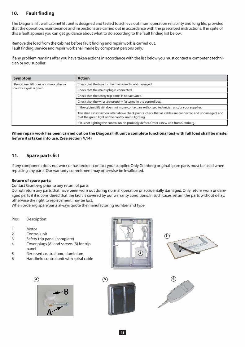
11. Spare parts list
If any component does not work or has broken, contact your supplier. Only Granberg original spare parts must be used when replacing any parts. Our warranty commitment may otherwise be invalidated.
Return of spare parts:Contact Granberg prior to any return of parts. Do not return any parts that have been worn out during normal operation or accidentally damaged. Only return worn or dam-aged parts if it is considered that the fault is covered by our warranty conditions. In such cases, return the parts without delay, otherwise the right to replacement may be lost.When ordering spare parts always quote the manufacturing number and type.
Pos: Description: 1 Motor2 Control unit3 Safety trip panel (complete)4 Cover plugs (A) and screws (B) for trip panel5 Recessed control box, aluminium6 Handheld control unit with spiral cable
Symptom Action
The cabinet lift does not move when a control signal is given
Check that the fuse for the mains feed is not damaged.
Check that the mains plug is connected.
Check that the safety trip panel is not actuated.
Check that the wires are properly fastened in the control box.
If the cabinet lift still does not move contact an authorized technician and/or your supplier.
This shall as first action, after above check points, check that all cables are connected and undamaged, and that the green light on the control unit is lighting.
If it is not lighting the control unit is probably defect. Order a new unit from Granberg.

19
A control unit, containing contactor and a transformer for 24 V DC control voltage shall be connected to 230 V, 50 Hz or 120 V 60 Hz (Depends on model) wall socket. The power consumption is only 345 W (230 V) or 324 W (120 V). Also the drive motor, operating on 24 V DC is connected to the control unit.
The control boxes and the safety trip panel are connected to the junction boxes in the upper part of the wall frame. These are then connected to the control box.
12. Electric system / Electric circuit diagram
Electric diagram
NOTE! The text “TOP OBEN” shall be turned upside down when the control box is installed.
(According Machinery Directive 2006/42/EG, Annexe 2A)
Manufacturer: Granberg Interior AB Tel. +46-11-19 77 50 Box 6112, Fax +46-11-12 76 76 SE-600 06 NORRKÖPING, Sweden
declares under sole responsibility that the product:
to which this declaration relates, is in manufactured in conformity with the following harmonised documents, following the provisions of Machinery Directive 2006/42/EG, the Low Voltage Directive 2006/95/EG and the EMC Directive 2004/108/EG.
It also conforms to the following harmonised standards:EN 60204-1 Safety of Machinery - Electrical Equipment of Machines -General RequirementsEN ISO 13857:2008 Safety distances to prevent hazard zones being reached by upper and lower limbs
Norrköping, 2012-12-07Granberg Interior AB
Tobias GranbergManaging Director
18. CE-Declaration of conformity
Space for machine plate
Red
Green
BlackRed
Yellow Down Up
Control box Linak CB09
Grey
Motor out
230V / 50 Hz / 1,5A* OR 120 V / 60 hz / 2,7A*
Safety trip panel
The picture shows a double wall socket, to which the control unit as well as the transformer for the lighting are connected.
* Depends on model

Box 6112 SE-600 06, Norrköping SwedenTel: +46 (0)11-19 77 50 Fax: +46 (0)11-12 76 76
E-mail: [email protected] - Internet: www.granberg.se