INSTRUCTION MANUAL Copyright © 2009 -...
45
INSTRUCTION MANUAL 9522B Iridium Satellite Modem & COM9522B Interface Modem August 2017 Copyright © 2009 - 201 7 Campbell Scientific (Canada) Corp.
Transcript of INSTRUCTION MANUAL Copyright © 2009 -...

INST
RU
CT
ION
MA
NU
AL
9522B Iridium Satellite Modem& COM9522B Interface Modem
August 2017
Copyright © 2009 - 2017 Campbell Scienti f ic (Canada) Corp.

1
Table of Contents 1. Overview ............................................................................................................................. 3
1.1. General Description and Modes of Operation ............................................................... 3 1.2. Modem Models and Accessories .................................................................................. 3 1.3. Hardware Overview...................................................................................................... 4 1.4. Power Control .............................................................................................................. 5 1.5. Global Coverage .......................................................................................................... 6
2. Specifications ...................................................................................................................... 6 2.1. 9522B Specifications .................................................................................................... 6 2.2. COM9522B Specifications............................................................................................ 7
3. Iridium SIM card & Modem Setup ........................................................................................ 7 3.1. Campbell Scientific Canada’s Field & Data Services..................................................... 7 3.2. Iridium SIM Card Use ................................................................................................... 8 3.3. Setup of Iridium Modems ............................................................................................. 8
3.3.1. Step 1: Hardware Connections ............................................................................. 8 3.3.2. Step 2: Start Hyperterminal................................................................................... 8 3.3.3. Step 3: Hyperterminal Connection Type ................................................................ 9 3.3.4. Step 4: Hyperterminal Port Settings .................................................................... 10 3.3.5. Step 5: Configuring Port Settings ........................................................................ 11 3.3.6. Step 6: Hyperterminal Communications .............................................................. 12
4. Datalogger Configuration ................................................................................................... 15 5. LoggerNet Configuration .................................................................................................... 16
5.1. Setup of Loggernet Communications .......................................................................... 16 5.1.1. Step 1: LoggerNet Setup .................................................................................... 16 5.1.2. Step 2: ComPort Configuration ........................................................................... 17 5.1.3. Step 3: Generic Modem Configuration ................................................................ 18 5.1.4. Step 4: Generic Modem Configuration Continued ............................................... 19 5.1.5. Step 5: PakBusPort Configuration ...................................................................... 20 5.1.6. Step 6: CR1000 Configuration ............................................................................ 21
6. Remote Modem Configuration ........................................................................................... 23 6.1. Program Example 1 ................................................................................................... 23 6.2. Program Example 2 ................................................................................................... 24
7. Troubleshooting Tools and Tips ......................................................................................... 26 8. Appendix A: Sample Data Transfer Calculations ................................................................ 28 9. Appendix B: Hardware Installation ..................................................................................... 30
9.1. SIM Card Installation .................................................................................................. 30 9.2. Antenna Installation.................................................................................................... 31 9.3. 9522B Modem Installation .......................................................................................... 33
10. Appendix C: Unlocking a SIM Card ................................................................................ 34 10.1. Handset Method ..................................................................................................... 34 10.2. Terminal Emulator Method ..................................................................................... 34
11. Appendix D: Interfacing Loggernet to RUDICS ............................................................... 36 11.1. Base Station System Requirements: ...................................................................... 36 11.2. Remote Station Requirements: ............................................................................... 36 11.3. Serial Port Redirector ............................................................................................. 36 11.4. Loggernet Setup..................................................................................................... 38
11.4.1. Step 1: ComPort Configuration ........................................................................... 38 11.4.2. Step 2: Generic Modem Configuration ................................................................ 39
9522B Iridium Satellite Modem _____________________________________________________________________________
2
Disclaimer
This manual addresses the concerns of interfacing another manufacturer’s product with Campbell Scientific Dataloggers. At the time of writing the information in this manual is currently accurate and up-to-date. However, changes to the manufacturer’s product are beyond our control. Such changes may affect equipment setup, configuration, and even safe use of the product. This manual should be used in conjunction with the original manufacturer’s technical information concerning product use and safety. If you encounter out-of-date, incomplete, or incorrect information, please contact us so we can attempt to remedy the situation. Because this product is manufactured by another company, their warranty applies. Contact the original manufacturer for warranty information, and servicing. Our website (www.campbellsci.ca) lists the updated manuals.
9522B Iridium Satellite Modem _____________________________________________________________________________
3
1. Overview
1.1. General Description and Modes of Operation
The Iridium satellite network consists of a constellation of 66 satellites situated in 6 planes in low-earth orbit. Each plane is populated by 11 satellites in polar orbits, giving the Iridium network excellent coverage in high latitudes that equatorial satellites often cannot reach. Iridium provides 5 different services: dial-up data, Short Burst Data (SBD), Short Messaging Service (SMS), Internet Connection, and Router Based Unrestricted Digital Internetworking Connectivity Solution (RUDICS). For the purposes of this manual we will discuss dial-up data and RUDICS as the preferred methods of connecting with Campbell Scientific dataloggers. However, while other services may not be directly relevant to datalogger operations, the end user may find them valuable. Please contact your Iridium service provider with questions on these methods.
1.2. Modem Models and Accessories
The Iridium Satellite System used with Campbell Scientific consists of the 9522B modem, COM9522B Interface Module kit, data cables, antenna and power supply. The base and remote stations utilize the same modem type, which both require a change to their configuration. The recommended connection of the remote modem to dataloggers, when possible is via the RS232 port. It is possible to communicate with a datalogger via either the CSI/O port or COM Ports 1-4. All datalogger connections will require appropriate cabling and interface accessories (See Table1). The COM9522B is required to connect the modem to the datalogger or computer and an appropriate power source. For remote applications where AC power is not available it is recommended to operate the modem on a schedule to avoid discharging the battery power supply. The antenna used for both Iridium modems is the SAF5350A mast mount antenna. For best signal reception the antenna should be mounted so that it has an unobstructed view of the sky and horizon. Reception quality changes as satellites move overhead so it is critical that the view be clear. See Section 7 of this manual for information about checking signal quality. For the ease of installation, the C2626 right angle SMA adaptor is used between the 9522B antenna connector and the
9522B Iridium Satellite Modem _____________________________________________________________________________
4
SAF5350A antenna cable. The antenna mounts to a ¾” diameter pipe which can be connected to a horizontal arm using a nu-rail connector. The nu-rail connector used will depend on the type of horizontal pipe. For a ¾” pipe, use #L1017, for a 1” pipe use #L1049.
Base Station Remote Station
9522B L-Band Data Modem 9522B L-Band Data Modem
L14394 Mounting Kit
SAF5350A antenna plus cable SAF5350A antenna plus cable
C2626 Right Angle SMA adaptor (may be required depending on installation)
C2626 Right Angle SMA adaptor
COM9522B COM9522B
Iridium SIM card (comes with modem)
Iridium SIM card (comes with modem)
L18663 Null Modem Cable (1ft lead)
SC932A with L10873 & SC12 (Only required if using CSI/O port of datalogger)
SC110 9-pin male DTE to bare leads (Only required if using a datalogger COM Port)
C2440 mounting kit for SAF5350A antenna C2440 mounting kit for SAF5350A antenna
L29796 and PS150 or L9591 and PS100 power supply
Table 1: Equipment List for Base and Remote Stations
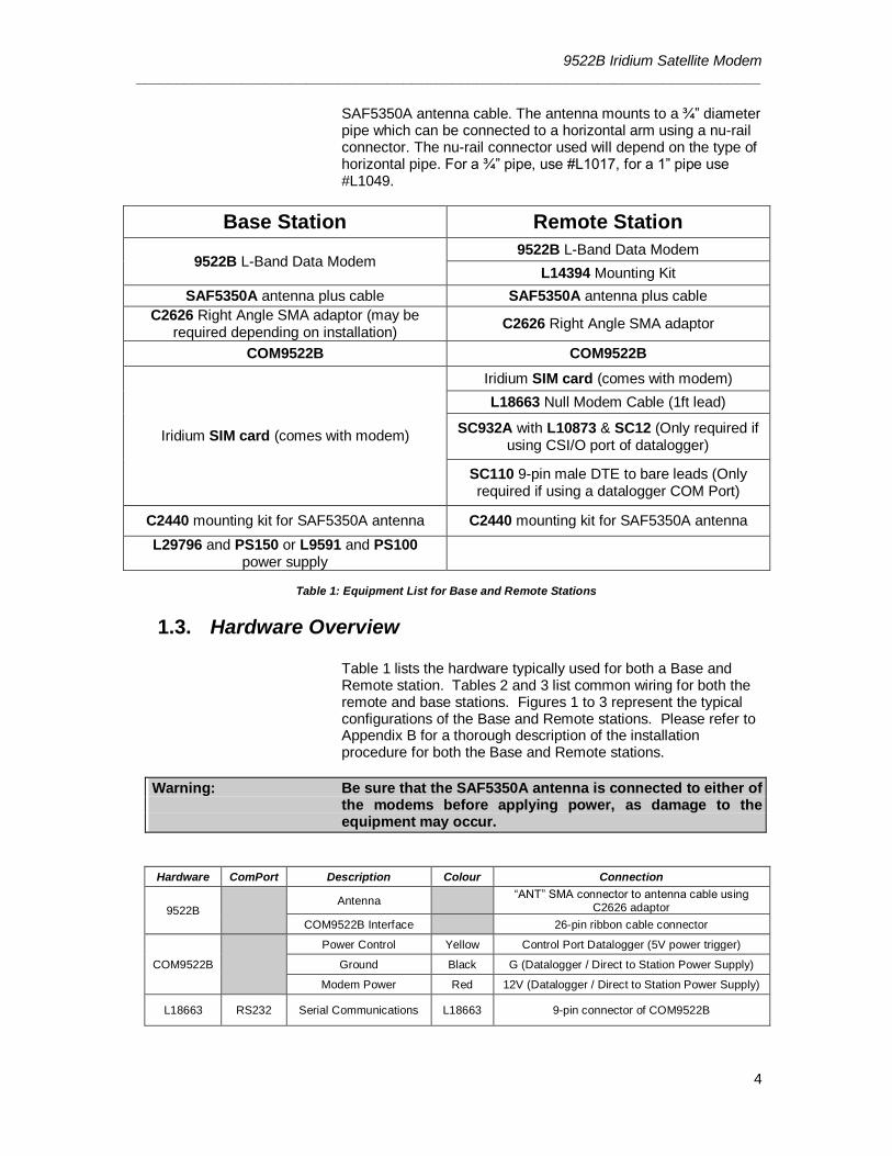
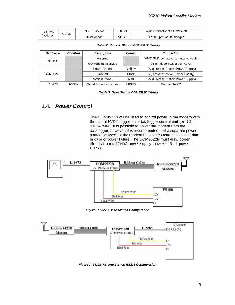
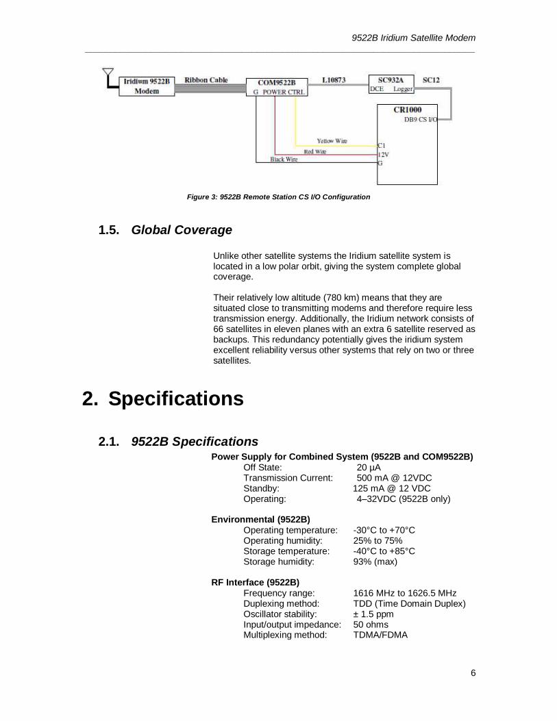
1.3. Hardware Overview Table 1 lists the hardware typically used for both a Base and Remote station. Tables 2 and 3 list common wiring for both the remote and base stations. Figures 1 to 3 represent the typical configurations of the Base and Remote stations. Please refer to Appendix B for a thorough description of the installation procedure for both the Base and Remote stations.
Warning: Be sure that the SAF5350A antenna is connected to either of the modems before applying power, as damage to the equipment may occur.
Hardware ComPort Description Colour Connection
9522B Antenna
“ANT” SMA connector to antenna cable using C2626 adaptor
COM9522B Interface 26-pin ribbon cable connector
COM9522B
Power Control Yellow Control Port Datalogger (5V power trigger)
Ground Black G (Datalogger / Direct to Station Power Supply)
Modem Power Red 12V (Datalogger / Direct to Station Power Supply)
L18663 RS232 Serial Communications L18663 9-pin connector of COM9522B
9522B Iridium Satellite Modem _____________________________________________________________________________
5
SC932A (optional)
CS I/O “DCE Device” L10873 9-pin connector of COM9522B
“Datalogger” SC12 CS I/O port of Datalogger
Table 2: Remote Station COM9522B Wiring
Hardware ComPort Description Colour Connection
9522B Antenna “ANT” SMA connector to antenna cable
COM9522B Interface 26-pin ribbon cable connector
COM9522B
Power Control Yellow 12V (Direct to Station Power Supply)
Ground Black G (Direct to Station Power Supply)
Modem Power Red 12V (Direct to Station Power Supply)
L10873 RS232 Serial Communications L10873 Connect to PC
Table 3: Base Station COM9522B Wiring
1.4. Power Control
The COM9522B will be used to control power to the modem with the use of 5VDC trigger on a datalogger control port (ex. C1: Yellow wire). It is possible to power the modem from the datalogger, however, it is recommended that a separate power source be used for the modem to avoid catastrophic loss of data in case of power failure. The COM9522B must draw power directly from a 12VDC power supply (power +: Red, power -: Black)
Figure 1: 9522B Base Station Configuration
Figure 2: 9522B Remote Station RS232 Configuration
9522B Iridium Satellite Modem _____________________________________________________________________________
6
Figure 3: 9522B Remote Station CS I/O Configuration
1.5. Global Coverage
Unlike other satellite systems the Iridium satellite system is located in a low polar orbit, giving the system complete global coverage. Their relatively low altitude (780 km) means that they are situated close to transmitting modems and therefore require less transmission energy. Additionally, the Iridium network consists of 66 satellites in eleven planes with an extra 6 satellite reserved as backups. This redundancy potentially gives the iridium system excellent reliability versus other systems that rely on two or three satellites.
2. Specifications
2.1. 9522B Specifications Power Supply for Combined System (9522B and COM9522B)
Off State: 20 µA Transmission Current: 500 mA @ 12VDC Standby: 125 mA @ 12 VDC Operating: 4–32VDC (9522B only)
Environmental (9522B)
Operating temperature: -30°C to +70°C Operating humidity: 25% to 75% Storage temperature: -40°C to +85°C Storage humidity: 93% (max)
RF Interface (9522B)
Frequency range: 1616 MHz to 1626.5 MHz Duplexing method: TDD (Time Domain Duplex) Oscillator stability: ± 1.5 ppm Input/output impedance: 50 ohms Multiplexing method: TDMA/FDMA
9522B Iridium Satellite Modem _____________________________________________________________________________
7
Mechanical (9522B) Length: 162 mm Width: 81 mm Depth: 28 mm Weight: 420 g (approximate)
2.2. COM9522B Specifications
Power Supply Operating: 9 – 18 VDC, 12VDC nominal
The COM9522B interface is capable of supplying up to 2500 mA of power to the Modem.
Max Supply Current: 2500 mA
Operating Temperature -40°C to +70°C Control Input Voltage
Guaranteed Off: < 1.25 volts Guaranteed On: > 3.24 volts Maximum Voltage: 18 VDC
Mechanical Length (with mounting ears): 201 mm Length (without mounting ears): 170 mm Width: 38 mm Weight: 476 g (approximate)
3. Iridium SIM card & Modem Setup
3.1. Campbell Scientific Canada’s Field & Data Services
CSC provides Field & Data Services provides service and assistance with the modem setup process, including but not limited to:
SIM Card setup and activation
Datalogger setup and configuration
LoggerNet configuration
Datalogger programming
Remote modem configuration
In-house testing and troubleshooting
Remote installation If you are interested, please contact Field & Data Services at 780-454-2505, or email [email protected].
9522B Iridium Satellite Modem _____________________________________________________________________________
8
In the case that you wish to configure the modem yourself, please refer to the following sections.
3.2. Iridium SIM Card Use
Please note that the new SIM cards that come with the Iridium modems are already unlocked. The SIM cards can be activated through Joubeh Technologies at: 11 Thornhill Dr., Suite 201 Dartmouth, NS, CANADA, B3B 1R9 T: (902) 405-4428 www.joubeh.com If you require that the SIM card be unlocked please see Appendix C. This should be done before going to the field.
3.3. Setup of Iridium Modems
Once the SIM cards are unlocked (Appendix C) it is necessary to set up the base and remote modems using a terminal emulation program such as ProComm, Hyperterminal. The following examples are taken using Hyperterminal.
3.3.1. Step 1: Hardware Connections
Connect the Iridium Satellite Modem to the COM9522B and connect a serial cable from the COM9522B to a COM Port on your computer. Connect the COM9522B to the power supply. Be sure to connect the Yellow power control wire to +12V, so that the COM9522B will switch on power for the 9522B.
3.3.2. Step 2: Start Hyperterminal
Open a new session of Hyperterminal from the Start Menu under: Start, All Programs, Accessories, or Communications. Choose a name for the connection (Figure 4).

9522B Iridium Satellite Modem _____________________________________________________________________________
9
Figure 4: Starting a Hyperterminal Session
3.3.3. Step 3: Hyperterminal Connection Type
After clicking OK the next screen should resemble Figure 5. This screen allows you to select what type of connection you will establish.
Figure 5: Hyperterminal Connection Type
9522B Iridium Satellite Modem _____________________________________________________________________________
10
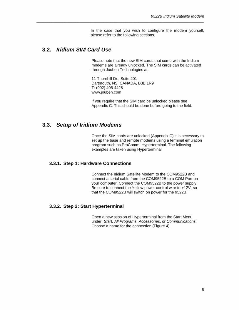
Click on the pull down tab next to the box marked ‘Connect using’. Select the COM port to which the modem is currently connected. In this example we use COM1 (Figure 6). Click OK.
Figure 6: Hyperterminal ComPort Connection
3.3.4. Step 4: Hyperterminal Port Settings
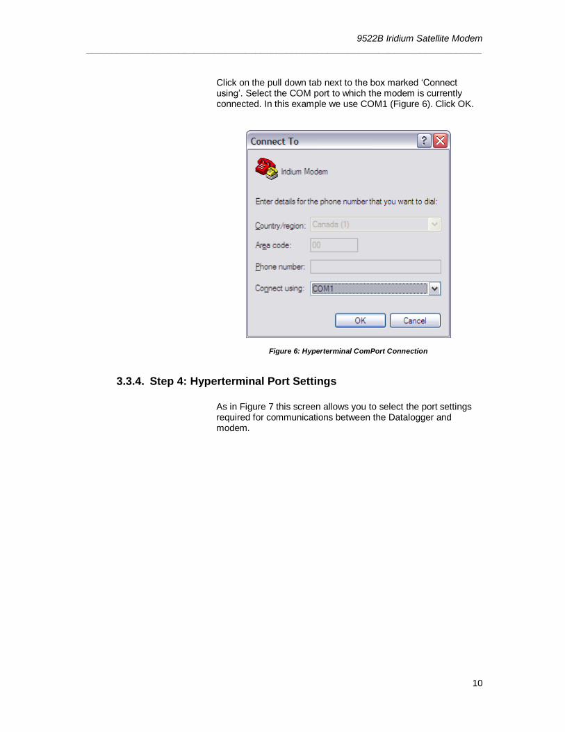
As in Figure 7 this screen allows you to select the port settings required for communications between the Datalogger and modem.
9522B Iridium Satellite Modem _____________________________________________________________________________
11
Figure 7: Hyperterminal Port Settings
3.3.5. Step 5: Configuring Port Settings
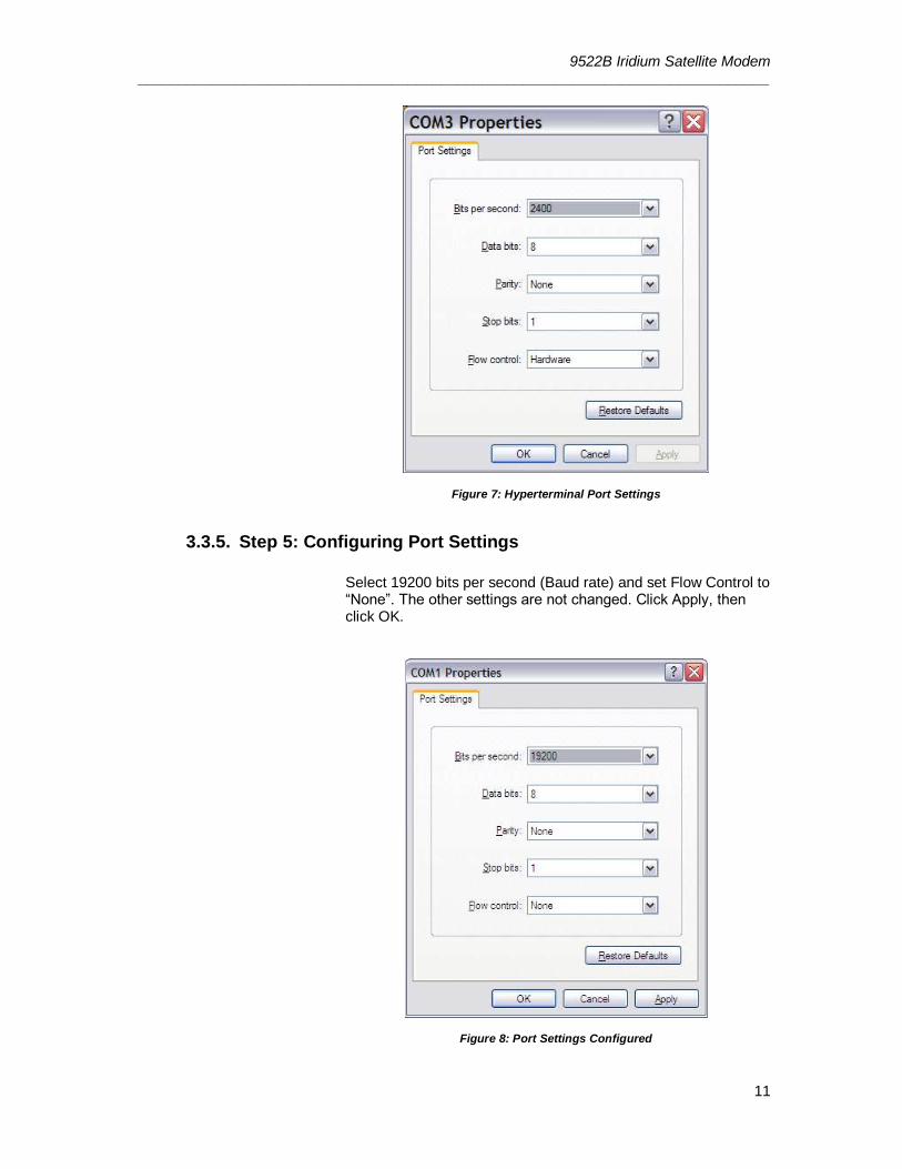
Select 19200 bits per second (Baud rate) and set Flow Control to “None”. The other settings are not changed. Click Apply, then click OK.
Figure 8: Port Settings Configured
9522B Iridium Satellite Modem _____________________________________________________________________________
12
3.3.6. Step 6: Hyperterminal Communications
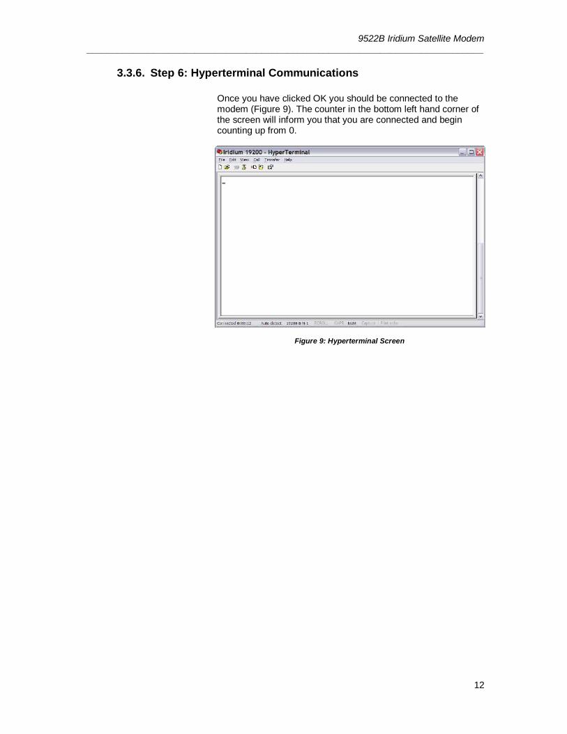
Once you have clicked OK you should be connected to the modem (Figure 9). The counter in the bottom left hand corner of the screen will inform you that you are connected and begin counting up from 0.
Figure 9: Hyperterminal Screen
9522B Iridium Satellite Modem _____________________________________________________________________________
13
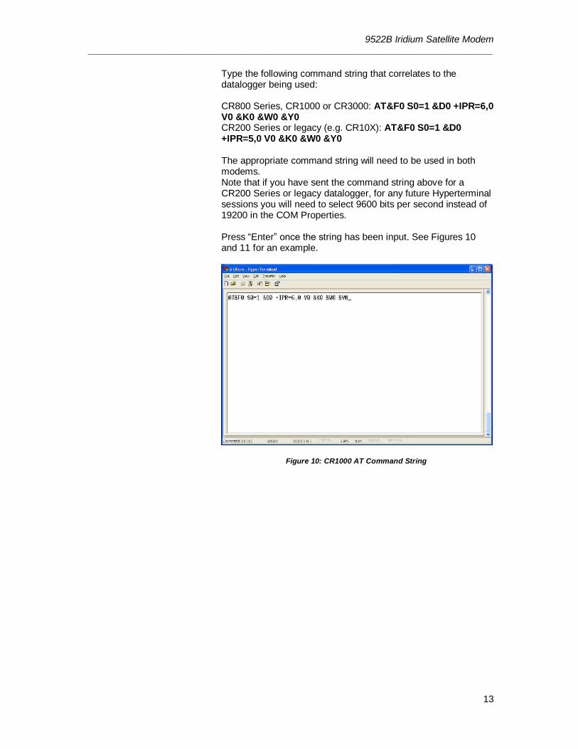
Type the following command string that correlates to the datalogger being used: CR800 Series, CR1000 or CR3000: AT&F0 S0=1 &D0 +IPR=6,0 V0 &K0 &W0 &Y0 CR200 Series or legacy (e.g. CR10X): AT&F0 S0=1 &D0 +IPR=5,0 V0 &K0 &W0 &Y0 The appropriate command string will need to be used in both modems. Note that if you have sent the command string above for a CR200 Series or legacy datalogger, for any future Hyperterminal sessions you will need to select 9600 bits per second instead of 19200 in the COM Properties. Press “Enter” once the string has been input. See Figures 10 and 11 for an example.
Figure 10: CR1000 AT Command String
9522B Iridium Satellite Modem _____________________________________________________________________________
14
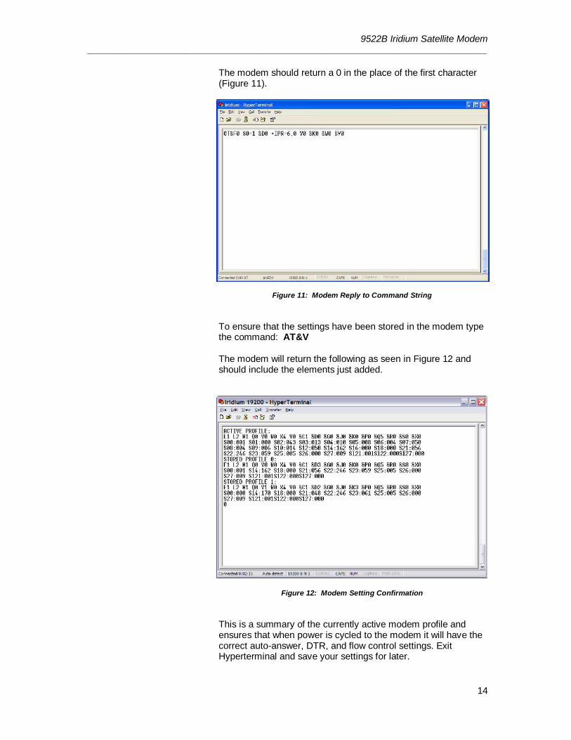
The modem should return a 0 in the place of the first character (Figure 11).
Figure 11: Modem Reply to Command String
To ensure that the settings have been stored in the modem type the command: AT&V The modem will return the following as seen in Figure 12 and should include the elements just added.
Figure 12: Modem Setting Confirmation
This is a summary of the currently active modem profile and ensures that when power is cycled to the modem it will have the correct auto-answer, DTR, and flow control settings. Exit Hyperterminal and save your settings for later.
9522B Iridium Satellite Modem _____________________________________________________________________________
15
4. Datalogger Configuration
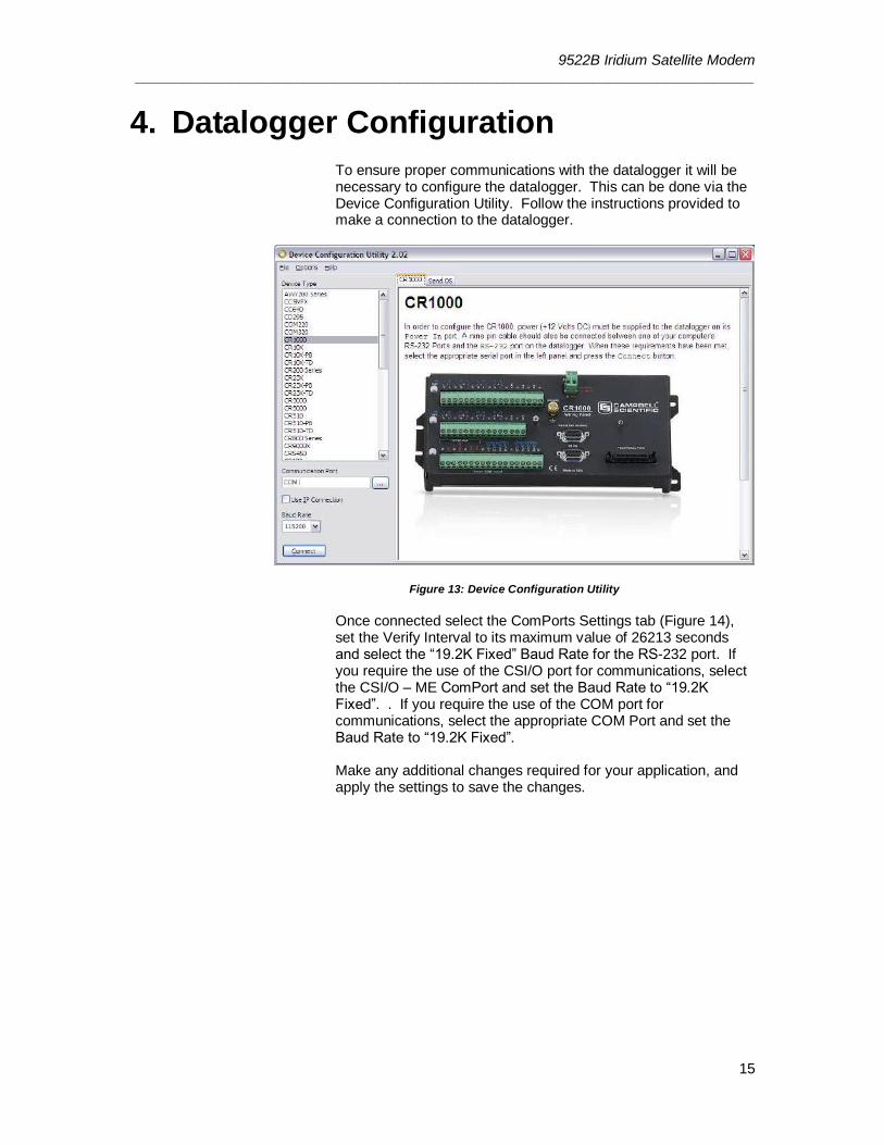
To ensure proper communications with the datalogger it will be necessary to configure the datalogger. This can be done via the Device Configuration Utility. Follow the instructions provided to make a connection to the datalogger.
Figure 13: Device Configuration Utility
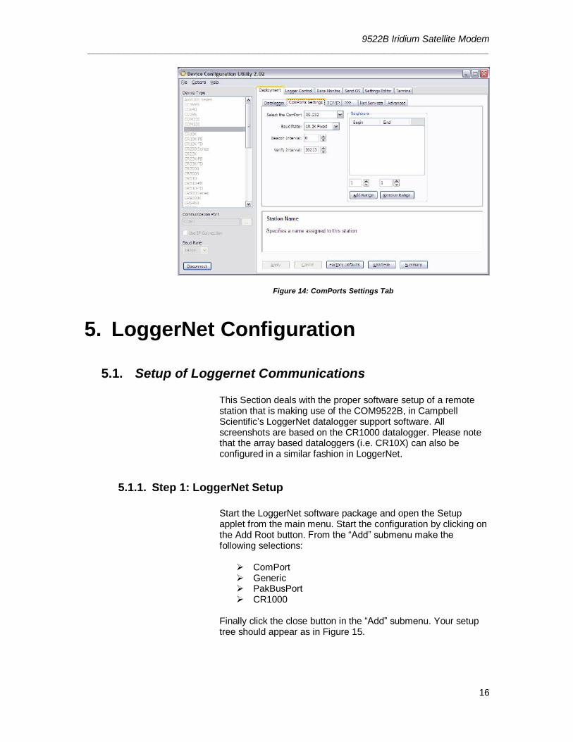
Once connected select the ComPorts Settings tab (Figure 14), set the Verify Interval to its maximum value of 26213 seconds and select the “19.2K Fixed” Baud Rate for the RS-232 port. If you require the use of the CSI/O port for communications, select the CSI/O – ME ComPort and set the Baud Rate to “19.2K Fixed”. . If you require the use of the COM port for communications, select the appropriate COM Port and set the Baud Rate to “19.2K Fixed”. Make any additional changes required for your application, and apply the settings to save the changes.
9522B Iridium Satellite Modem _____________________________________________________________________________
16
Figure 14: ComPorts Settings Tab
5. LoggerNet Configuration
5.1. Setup of Loggernet Communications
This Section deals with the proper software setup of a remote station that is making use of the COM9522B, in Campbell Scientific’s LoggerNet datalogger support software. All screenshots are based on the CR1000 datalogger. Please note that the array based dataloggers (i.e. CR10X) can also be configured in a similar fashion in LoggerNet.
5.1.1. Step 1: LoggerNet Setup
Start the LoggerNet software package and open the Setup applet from the main menu. Start the configuration by clicking on the Add Root button. From the “Add” submenu make the following selections:
ComPort Generic PakBusPort CR1000
Finally click the close button in the “Add” submenu. Your setup tree should appear as in Figure 15.
9522B Iridium Satellite Modem _____________________________________________________________________________
17
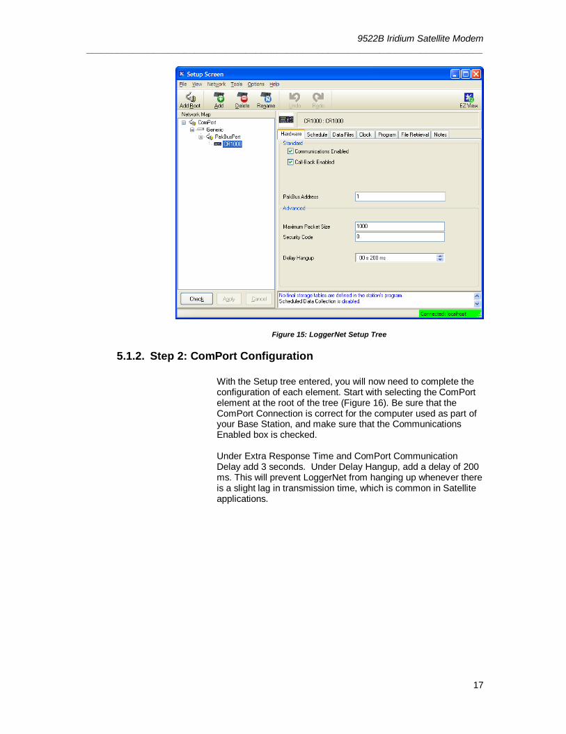
Figure 15: LoggerNet Setup Tree
5.1.2. Step 2: ComPort Configuration
With the Setup tree entered, you will now need to complete the configuration of each element. Start with selecting the ComPort element at the root of the tree (Figure 16). Be sure that the ComPort Connection is correct for the computer used as part of your Base Station, and make sure that the Communications Enabled box is checked. Under Extra Response Time and ComPort Communication Delay add 3 seconds. Under Delay Hangup, add a delay of 200 ms. This will prevent LoggerNet from hanging up whenever there is a slight lag in transmission time, which is common in Satellite applications.
9522B Iridium Satellite Modem _____________________________________________________________________________
18
Figure 16: ComPort Configuration
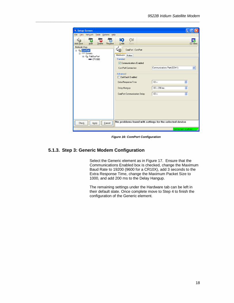
5.1.3. Step 3: Generic Modem Configuration
Select the Generic element as in Figure 17. Ensure that the Communications Enabled box is checked, change the Maximum Baud Rate to 19200 (9600 for a CR10X), add 3 seconds to the Extra Response Time, change the Maximum Packet Size to 1000, and add 200 ms to the Delay Hangup. The remaining settings under the Hardware tab can be left in their default state. Once complete move to Step 4 to finish the configuration of the Generic element.
9522B Iridium Satellite Modem _____________________________________________________________________________
19
Figure 17: Generic - Hardware Configuration
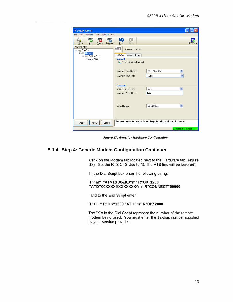
5.1.4. Step 4: Generic Modem Configuration Continued
Click on the Modem tab located next to the Hardware tab (Figure 18). Set the RTS CTS Use to “3. The RTS line will be lowered”. In the Dial Script box enter the following string: T"^m" "ATV1&D0&K0^m" R"OK"1200 "ATDT00XXXXXXXXXXXX^m" R"CONNECT"50000 and to the End Script enter: T"+++" R"OK"1200 "ATH^m" R"OK"2000 The “X”s in the Dial Script represent the number of the remote modem being used. You must enter the 12-digit number supplied by your service provider.
9522B Iridium Satellite Modem _____________________________________________________________________________
20
Figure 18: Generic - Modem Configuration
5.1.5. Step 5: PakBusPort Configuration
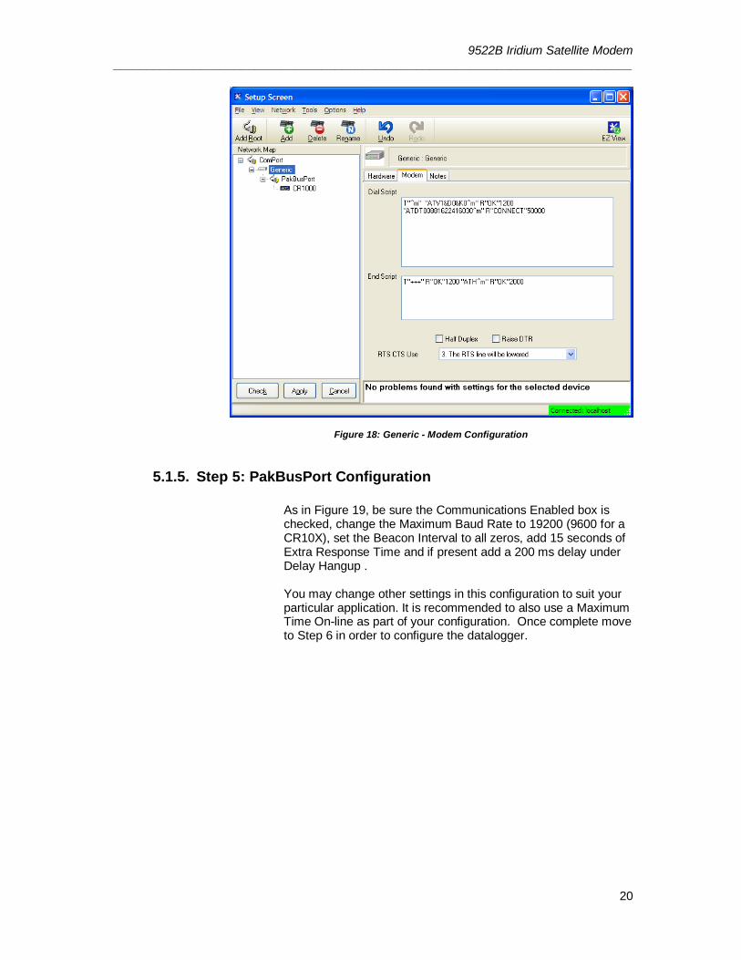
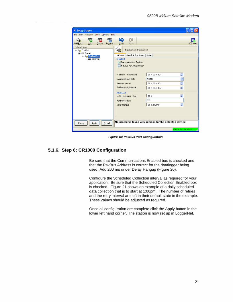
As in Figure 19, be sure the Communications Enabled box is checked, change the Maximum Baud Rate to 19200 (9600 for a CR10X), set the Beacon Interval to all zeros, add 15 seconds of Extra Response Time and if present add a 200 ms delay under Delay Hangup . You may change other settings in this configuration to suit your particular application. It is recommended to also use a Maximum Time On-line as part of your configuration. Once complete move to Step 6 in order to configure the datalogger.
9522B Iridium Satellite Modem _____________________________________________________________________________
21
Figure 19: PakBus Port Configuration
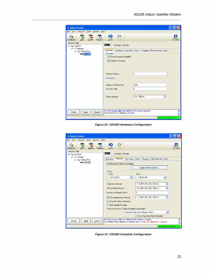
5.1.6. Step 6: CR1000 Configuration
Be sure that the Communications Enabled box is checked and that the PakBus Address is correct for the datalogger being used. Add 200 ms under Delay Hangup (Figure 20). Configure the Scheduled Collection interval as required for your application. Be sure that the Scheduled Collection Enabled box is checked. Figure 21 shows an example of a daily scheduled data collection that is to start at 1:00pm. The number of retries and the retry interval are left in their default state in the example. These values should be adjusted as required. Once all configuration are complete click the Apply button in the lower left hand corner. The station is now set up in LoggerNet.
9522B Iridium Satellite Modem _____________________________________________________________________________
22
Figure 20: CR1000 Hardware Configuration
Figure 21: CR1000 Schedule Configuration
9522B Iridium Satellite Modem _____________________________________________________________________________
23
6. Remote Modem Configuration
As a matter of system redundancy it is recommended that the following programming be used as part of your datalogger program. If this programming is not used it is possible that the remote modem may lose it’s configuration. If this occurs remote communication will no longer be available. The program examples are for a CR1000, but are adaptable to the CR800 series, and CR3000 dataloggers.
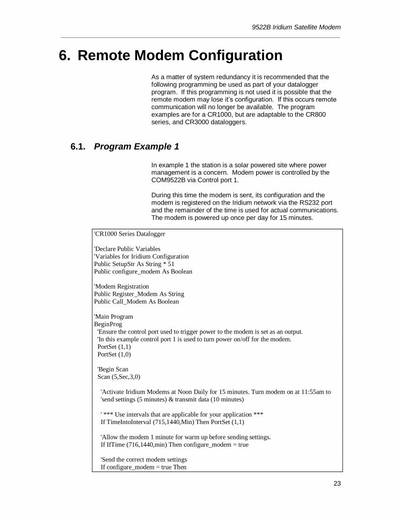
6.1. Program Example 1 In example 1 the station is a solar powered site where power management is a concern. Modem power is controlled by the COM9522B via Control port 1. During this time the modem is sent, its configuration and the modem is registered on the Iridium network via the RS232 port and the remainder of the time is used for actual communications. The modem is powered up once per day for 15 minutes.
'CR1000 Series Datalogger
'Declare Public Variables
'Variables for Iridium Configuration
Public SetupStr As String * 51
Public configure_modem As Boolean
'Modem Registration
Public Register_Modem As String
Public Call_Modem As Boolean
'Main Program
BeginProg
'Ensure the control port used to trigger power to the modem is set as an output.
'In this example control port 1 is used to turn power on/off for the modem.
PortSet (1,1)
PortSet (1,0)
'Begin Scan
Scan (5,Sec,3,0)
'Activate Iridium Modems at Noon Daily for 15 minutes. Turn modem on at 11:55am to
'send settings (5 minutes) & transmit data (10 minutes)
' *** Use intervals that are applicable for your application ***
If TimeIntoInterval (715,1440,Min) Then PortSet (1,1)
'Allow the modem 1 minute for warm up before sending settings.
If IfTime (716,1440,min) Then configure_modem = true
'Send the correct modem settings
If configure_modem = true Then
9522B Iridium Satellite Modem _____________________________________________________________________________
24
SerialOpen (ComRS232,19200,0,0,2000)
Delay (0,1,Sec)
'Send the correct settings
SetupStr = "AT&F0 S0=1 &D0 +IPR=6,0 V0 &K0 &W0 &Y0" & CHR(13) & CHR(10)
SerialOut (ComRS232,SetupStr,"",0,0)
configure_modem = false
SerialClose (ComRS232)
EndIf
'Once settings are sent to the modem allow 2 minutes before sending the modem
'registeration command to the modem.
If IfTime (718,1440,min) Then Call_Modem = true
'Send ATDT dialing command from 9522B to force modem registration on Iridium
network
If Call_Modem = True
SerialOpen (ComRS232,19200,0,0,2000)
Delay (0,1, sec)
Register_Modem = "ATDT1234" & CHR(13) & CHR(10)
SerialOut (ComRS232,Register_Modem,"",0,0) Call_Modem = False
SerialClose (ComRS232)
EndIf
'Turn modem off at 12:10pm
If TimeIntoInterval (730,1440,Min) Then PortSet (1,0)
NextScan
EndProg
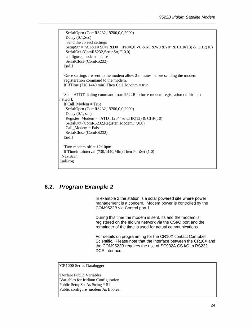
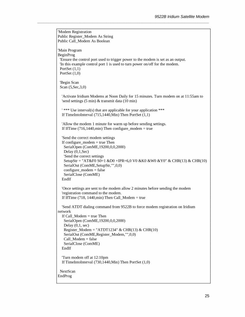
6.2. Program Example 2
In example 2 the station is a solar powered site where power management is a concern. Modem power is controlled by the COM9522B via Control port 1. During this time the modem is sent, its and the modem is registered on the Iridium network via the CSI/O port and the remainder of the time is used for actual communications. For details on programming for the CR10X contact Campbell Scientific. Please note that the interface between the CR10X and the COM9522B requires the use of SC932A CS I/O to RS232 DCE interface.
'CR1000 Series Datalogger
'Declare Public Variables
'Variables for Iridium Configuration
Public SetupStr As String * 51
Public configure_modem As Boolean
9522B Iridium Satellite Modem _____________________________________________________________________________
25
'Modem Registration
Public Register_Modem As String
Public Call_Modem As Boolean
'Main Program
BeginProg
'Ensure the control port used to trigger power to the modem is set as an output.
'In this example control port 1 is used to turn power on/off for the modem.
PortSet (1,1) PortSet (1,0)
'Begin Scan
Scan (5,Sec,3,0)
'Activate Iridium Modems at Noon Daily for 15 minutes. Turn modem on at 11:55am to
'send settings (5 min) & transmit data (10 min)
' *** Use interval(s) that are applicable for your application ***
If TimeIntoInterval (715,1440,Min) Then PortSet (1,1)
'Allow the modem 1 minute for warm up before sending settings.
If IfTime (716,1440,min) Then configure_modem = true
'Send the correct modem settings
If configure_modem = true Then
SerialOpen (ComME,19200,0,0,2000)
Delay (0,1,Sec)
'Send the correct settings
SetupStr = "AT&F0 S0=1 &D0 +IPR=6,0 V0 &K0 &W0 &Y0" & CHR(13) & CHR(10)
SerialOut (ComME,SetupStr,"",0,0)
configure_modem = false SerialClose (ComME)
EndIf
'Once settings are sent to the modem allow 2 minutes before sending the modem
'registration command to the modem.
If IfTime (718, 1440,min) Then Call_Modem = true
'Send ATDT dialing command from 9522B to force modem registration on Iridium
network
If Call_Modem = true Then
SerialOpen (ComME,19200,0,0,2000)
Delay (0,1, sec) Register_Modem = "ATDT1234" & CHR(13) & CHR(10)
SerialOut (ComME,Register_Modem,"",0,0)
Call_Modem = false
SerialClose (ComME)
EndIf
'Turn modem off at 12:10pm
If TimeIntoInterval (730,1440,Min) Then PortSet (1,0)
NextScan
EndProg
9522B Iridium Satellite Modem _____________________________________________________________________________
26
7. Troubleshooting Tools and Tips
Problem: I have intermittent successful connections between the remote and base station modem. The signal strength is weak and the data transfer speeds are slow. Solution: The antenna may not have a complete 180° view of the sky. Some objects and debris such as snow and trees can interfere with communications. Make sure that there are no obstructions to the antennas when installing. You may need to reposition or elevate your antenna to obtain the best reception. The Signal Quality AT command can be used to confirm signal strength during the installation/repositioning of the antenna. This will require the use of a laptop connected to the COM9522B interface and a terminal emulator. Once the terminal emulator is connected the following command can be entered to check signal strength:
AT+CSQ The modem should return a value of between 0 and 5 within 10 seconds. Attempt to get the largest value during your installation/repositioning. Problem: LoggerNet immediately brings back an error message saying that communications with the station have failed. Solution: Sometimes PakBus© beacons sent to other stations by LoggerNet interfere with successful communications using Iridium Satellite Modems. Either turn PakBus© beaconing off or disable communications with your other stations when you attempt to download using Iridium. This can be accomplished in the Setup applet in LoggerNet. Finally, reboot LoggerNet to clear the communications queue of any tasks. Problem: Loggernet makes several attempts to connect to the remote station with no success. The failure is not immediate and the Loggernet LogTool may show a “No Carrier Detected” error. Solution: It is possible that the base modem has lost it’s configuration. Resend the configuration as shown in Section 2.2 of this manual and attempt communications again. Problem: I am using Iridium to communicate through the CS I/O port on my datalogger. Whenever I try connecting with the datalogger LoggerNet reports that communication with the station has failed. This message takes several seconds to appear. Solution: You may have connected your SC932A device backwards at the remote station. When you install the SC932A it is imperative to make sure that the device is connected in the

9522B Iridium Satellite Modem _____________________________________________________________________________
27
proper way. Follow the label on the device for the proper connections.
9522B Iridium Satellite Modem _____________________________________________________________________________
28
8. Appendix A: Sample Data Transfer Calculations
Note: The calculations below are based upon maximum theoretical throughputs. Real world transmission times for the Iridium Satellite Network have proven to be as much as twice as slow.
When transmitting the data back from the station, the power consumption of the modem must be taken into account in order to avoid excessive discharge of the battery power supply. To get an idea of what the transmission time and associated power drain might be for a typical metrological station, consider the following example: A station measures wind-speed and direction, precipitation, temperature and relative humidity, solar radiation, and barometric pressure. The datalogger is a CR1000. The monthly data file contains 2 data tables; a small maintenance table and a 30 parameter meteorological data table. The size of a monthly ASCII data file is 124Kb. If the station’s data were downloaded monthly, the time (T) for the data transfer could be calculated as shown below: T(Download) = File size (Kb) / Transfer Rate (10 Kb/min) With a file size of 124 Kb and a transfer rate of 10 Kbytes per minute, the download time is approximately 13 minutes. If the data were downloaded daily, the file would be much smaller, approximately 5KB. A daily data transfer time would be approximately 30 seconds. Please note that a 15 second connection time should be added to the above times to account for the initial connection time. Table 4 below shows the transfer time depending on whether data is collected daily, weekly or monthly.
Collection Interval File size (Kbytes) Transfer time
Monthly 124 13 minutes
Weekly 35 3.5 minutes
Daily 5 30 seconds
Table 4: Data Transfer Time Estimates
The CR10X datalogger generates data arrays which are very similar in size to the table-based dataloggers. For example the station mentioned above generates a 124 Kb meteorological data table and a 2 Kb maintenance table each month. If a CR10X is employed to measure the same parameters the data arrays would be the same size.

9522B Iridium Satellite Modem _____________________________________________________________________________
29
Power Calculation
Note: When configuring a power supply (i.e. solar panel and battery) for a remote station it essential to design with the worst case scenario in mind. This will help to ensure that the station will perform as expected.
The power calculation for data transfer can be carried out now that the transfer time is known. The modem has the following power consumption characteristics @ 12VDC: - 0 mA when powered off - 125 mA stand-by - 500 mA transmit (2500mA max) The time slot for powering the modem must be long enough to allow for the complete downloading of the datalogger’s data and connection times. Refer to Table 2 or make your own calculation based on the collection interval you intend to use. It is advisable to make the time slot longer than the minimum download time required to allow for initial connection times and possible retries. It is also advisable to arrange the time slot during a time of day when the power supply is its most robust. For a solar powered station this would be the early afternoon. The periods of power consumption in a day can be divided up as follows: Period A: the modem is powered off – 0 mA Period B: the modem powered up in stand-by mode –300mA Period C: the modem is transmitting the data – 2500mA 26.5Now consider a 35 Kbyte data file size and a datalogger programmed power time slot of 1/2 hour; the Periods above become: Period A = 24 hours - Period B – Period C Period B = 30 minutes – Period C Period C = 3.5 minutes (from Table 2) We can substitute in the Period B and C values to obtain all Periods: Period A = 23.5 hours = 0.0 Ah/Day Period B = 26.5 minutes @ 125 mA = 0.061 Ah/Day Period C = 3.5 minutes @500mA = 0.004 Ah/Day The total draw for the data transfer is the sum of the periods, 0.065 Ah/Day, one day per week.
Note: The Ah/Day calculation for each period is as follows: = Current Draw in mA * (Interval in minutes / 60 min) / 1000
9522B Iridium Satellite Modem _____________________________________________________________________________
30
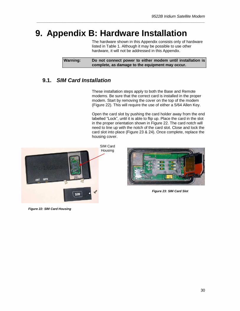
9. Appendix B: Hardware Installation The hardware shown in this Appendix consists only of hardware listed in Table 1. Although it may be possible to use other hardware, it will not be addressed in this Appendix.
Warning: Do not connect power to either modem until installation is complete, as damage to the equipment may occur.
9.1. SIM Card Installation
These installation steps apply to both the Base and Remote modems. Be sure that the correct card is installed in the proper modem. Start by removing the cover on the top of the modem (Figure 22). This will require the use of either a 5/64 Allen Key. Open the card slot by pushing the card holder away from the end labelled “Lock”, until it is able to flip up. Place the card in the slot in the proper orientation shown in Figure 22. The card notch will need to line up with the notch of the card slot. Close and lock the card slot into place (Figure 23 & 24). Once complete, replace the housing cover.
Figure 22: SIM Card Housing
Figure 23: SIM Card Slot
SIM Card
Housing
9522B Iridium Satellite Modem _____________________________________________________________________________
31
Figure24: Installed SIM Card
9.2. Antenna Installation
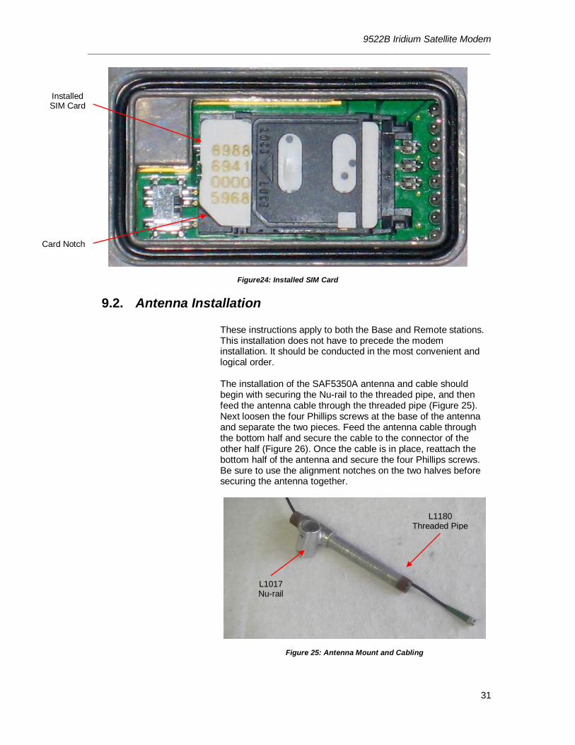
These instructions apply to both the Base and Remote stations. This installation does not have to precede the modem installation. It should be conducted in the most convenient and logical order. The installation of the SAF5350A antenna and cable should begin with securing the Nu-rail to the threaded pipe, and then feed the antenna cable through the threaded pipe (Figure 25). Next loosen the four Phillips screws at the base of the antenna and separate the two pieces. Feed the antenna cable through the bottom half and secure the cable to the connector of the other half (Figure 26). Once the cable is in place, reattach the bottom half of the antenna and secure the four Phillips screws. Be sure to use the alignment notches on the two halves before securing the antenna together.
Figure 25: Antenna Mount and Cabling
Installed SIM Card
L1180 Threaded Pipe
L1017 Nu-rail
Card Notch
9522B Iridium Satellite Modem _____________________________________________________________________________
32
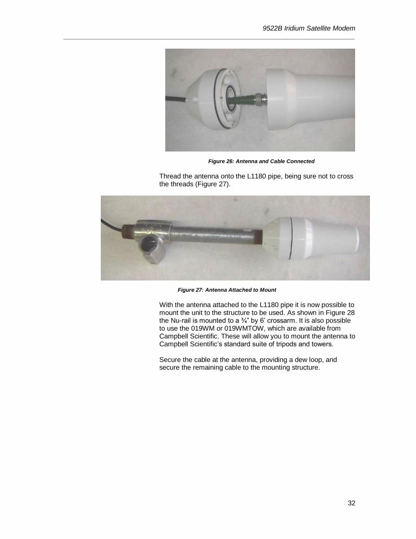
Figure 26: Antenna and Cable Connected
Thread the antenna onto the L1180 pipe, being sure not to cross the threads (Figure 27).
Figure 27: Antenna Attached to Mount
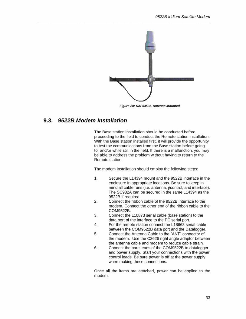
With the antenna attached to the L1180 pipe it is now possible to mount the unit to the structure to be used. As shown in Figure 28 the Nu-rail is mounted to a ¾” by 6’ crossarm. It is also possible to use the 019WM or 019WMTOW, which are available from Campbell Scientific. These will allow you to mount the antenna to Campbell Scientific’s standard suite of tripods and towers. Secure the cable at the antenna, providing a dew loop, and secure the remaining cable to the mounting structure.
9522B Iridium Satellite Modem _____________________________________________________________________________
33
Figure 28: SAF5350A Antenna Mounted
9.3. 9522B Modem Installation
The Base station installation should be conducted before proceeding to the field to conduct the Remote station installation. With the Base station installed first, it will provide the opportunity to test the communications from the Base station before going to, and/or while still in the field. If there is a malfunction, you may be able to address the problem without having to return to the Remote station. The modem installation should employ the following steps: 1. Secure the L14394 mount and the 9522B interface in the
enclosure in appropriate locations. Be sure to keep in mind all cable runs (i.e. antenna, j/control, and interface). The SC932A can be secured in the same L14394 as the 9522B if required.
2. Connect the ribbon cable of the 9522B interface to the modem. Connect the other end of the ribbon cable to the COM9522B.
3. Connect the L10873 serial cable (base station) to the data port of the interface to the PC serial port.
4. For the remote station connect the L18663 serial cable between the COM9522B data port and the Datalogger.
5. Connect the Antenna Cable to the “ANT” connector of the modem. Use the C2626 right angle adaptor between the antenna cable and modem to reduce cable strain.
6. Connect the bare leads of the COM9522B to datalogger and power supply. Start your connections with the power control leads. Be sure power is off at the power supply when making these connections.
Once all the items are attached, power can be applied to the modem.
9522B Iridium Satellite Modem _____________________________________________________________________________
34
10. Appendix C: Unlocking a SIM Card There are two methods to unlock a SIM Card, and the equipment you have available will dictate which method is used.
10.1. Handset Method To unlock the Iridium SIM card permanently using the Iridium Handset follow these instructions. Install the SIM card, attach the antenna, and 9522B interface. Attach the handset as required. Apply power to the modem. The handset will request the PIN number before proceeding. Once you enter the PIN number (default 1111) the modem will register itself. You will need to navigate the menus of the handset as follows:
Find “PHONE SETUP”, click ok
From this menu select “REQUIRE SIM PIN”
Navigate until “OFF” is displayed, select by clicking ok
Exit out of the menus once the PIN requirement is deactivated.
With the card unlocked you can continue with your modem setup.
10.2. Terminal Emulator Method In order to unlock the SIM cards with this method you will need a terminal emulator like Hyperterminal. The configuration will need to be same as list in Section 2.2 of this manual. Refer to Section 2.2 for this setup. NOTE: Both SIM Cards must be unlocked. When conducting these steps you will need to have the SIM Card installed in the modem. The antenna must be connected, and have a sky view for communications with the satellite network. Finally the unit must be powered. Refer to the appropriate Sections of this manual for information about these requirements.
9522B Iridium Satellite Modem _____________________________________________________________________________
35
Once the modem and terminal emulator are ready enter the following command: AT+CPIN? <Enter> The command requests that the modem respond as to whether a password is required. The expected modem response is: +CPIN: SIM PIN The response confirms that the SIM Card PIN1 code is required to unlock the Card. If you get a different response, contact the SIM Card provider to determine if a different code is required. If you get a response of “+CPIN: SIM PIN2” this may mean that the Card is already unlocked or requires a different code. The next step is to enter the PIN code for the SIM Card. AT+CPIN=”1111” <Enter> The modem should response with an “OK” which means the PIN code has been accepted. This explanation assumes that the default code of “1111” is being used. If you get an “ERROR” reply, be sure that the command was entered as shown. If you continue to get an error response, contact the SIM Card provider to determine if a different code is required. The next step is to enter the command to deactivate the PIN code requirement. If your PIN code is different from the “1111” then use this in the command in its place. AT+CLCK=”SC”,0,”1111” <Enter> The modem should respond with an “OK” which means the command has been accepted. If you get an “ERROR” reply, be sure that the command was entered as shown. If you continue to get an error response, contact the SIM Card provider for further information. The final step should be to test that the SIM Card is unlocked and will remain unlocked. Start by powering down the modem and then reapplying power. Allow the modem to warm up for about 30 seconds. The test consists of attempting to dial the 12-digit data number for the other SIM Card in the terminal emulator. ATDT00<12-DIGIT DATA #> <Enter> If you are able to dial the number without getting a prompt for a PIN code then the code requirement is deactivated. The modem should respond with “NO ANSWER” after several seconds. This assumes the other modem is not communicating.
9522B Iridium Satellite Modem _____________________________________________________________________________
36
11. Appendix D: Interfacing Loggernet to RUDICS
If you require assistance, refer to Section 3.1 for information on Campbell Scientific Canada’s Field & Data Services. Field & Data Services can be contacted at 780-454-2505 or [email protected].
11.1. Base Station System Requirements: 1. Loggernet Software version 4.0 or greater 2. Telnet compliant Serial Port Redirector software 3. Iridium service account, supplied by Iridium Service Provider.
Will also need to make arrangements with Service Provider to access the RUDICS network.
4. A PC with static IP internet access 5. Loggernet and Serial Port Redirector software should be
referenced for relevant PC hardware requirements
11.2. Remote Station Requirements:
1. Datalogger configured as described in Sections 4, 5.1.5 & 5.1.6
2. Datalogger program should include modem configuration (section 6)
3. Modem configured as described in Section 3.2
11.3. Serial Port Redirector In order to communicate with a remote datalogger using RUDICS, the computer running LoggerNet must have telnet compliant serial port redirector software installed (also known as a serial port to telnet emulator software). Currently compatible software can be found here. The software version tested at Campbell and known to operate is version 2.6.1. http://www.fabulatech.com/serial-port-redirector.html
Note: Campbell Scientific cannot guarantee that other versions of this software will operate as intended in this application. Any support will need to be requested directly of any third party software provider.
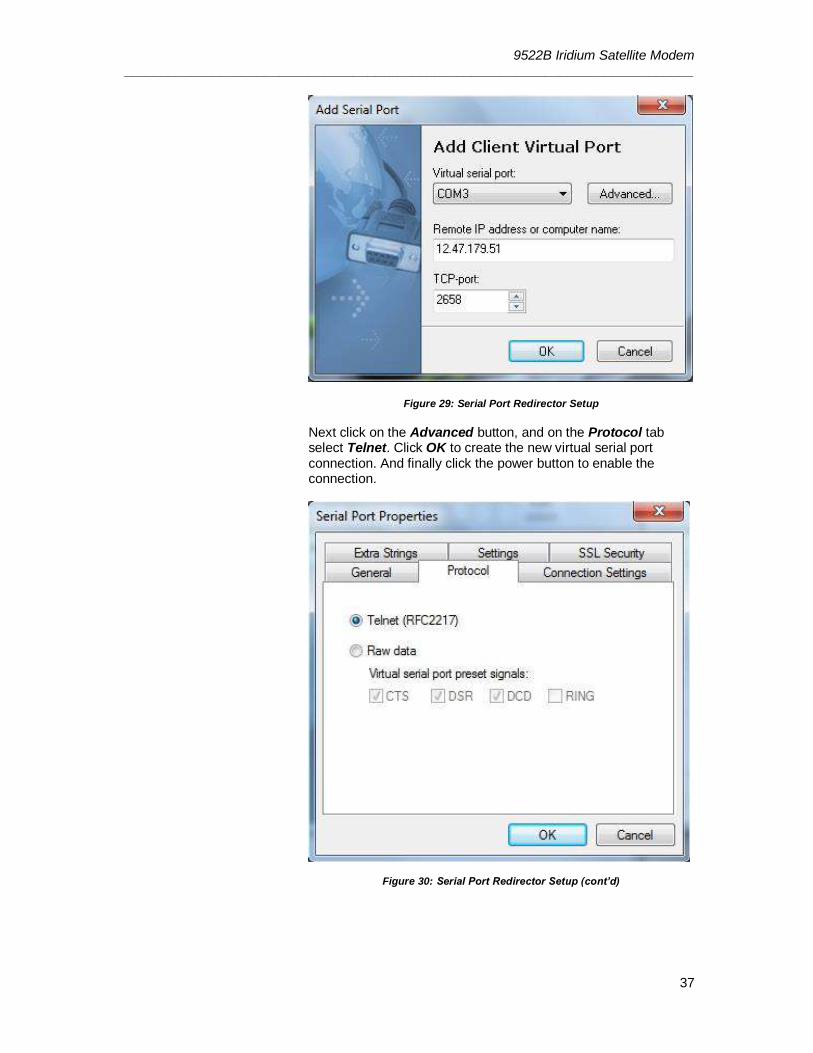
Once the software is installed, click on the Add Client Virtual Port button to create a connection to the RUDICS system. Fill in the information in the Add Serial Port window, select an unused serial port and add the IP address and port number to connect too.
9522B Iridium Satellite Modem _____________________________________________________________________________
37
Figure 29: Serial Port Redirector Setup Next click on the Advanced button, and on the Protocol tab select Telnet. Click OK to create the new virtual serial port connection. And finally click the power button to enable the connection.
Figure 30: Serial Port Redirector Setup (cont’d)
9522B Iridium Satellite Modem _____________________________________________________________________________
38
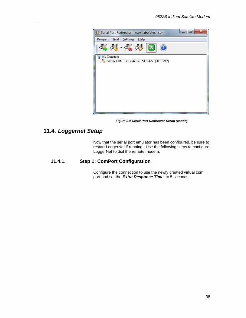
Figure 31: Serial Port Redirector Setup (cont’d)
11.4. Loggernet Setup Now that the serial port emulator has been configured, be sure to restart LoggerNet if running. Use the following steps to configure LoggerNet to dial the remote modem.
11.4.1. Step 1: ComPort Configuration
Configure the connection to use the newly created virtual com port and set the Extra Response Time to 5 seconds.
9522B Iridium Satellite Modem _____________________________________________________________________________
39
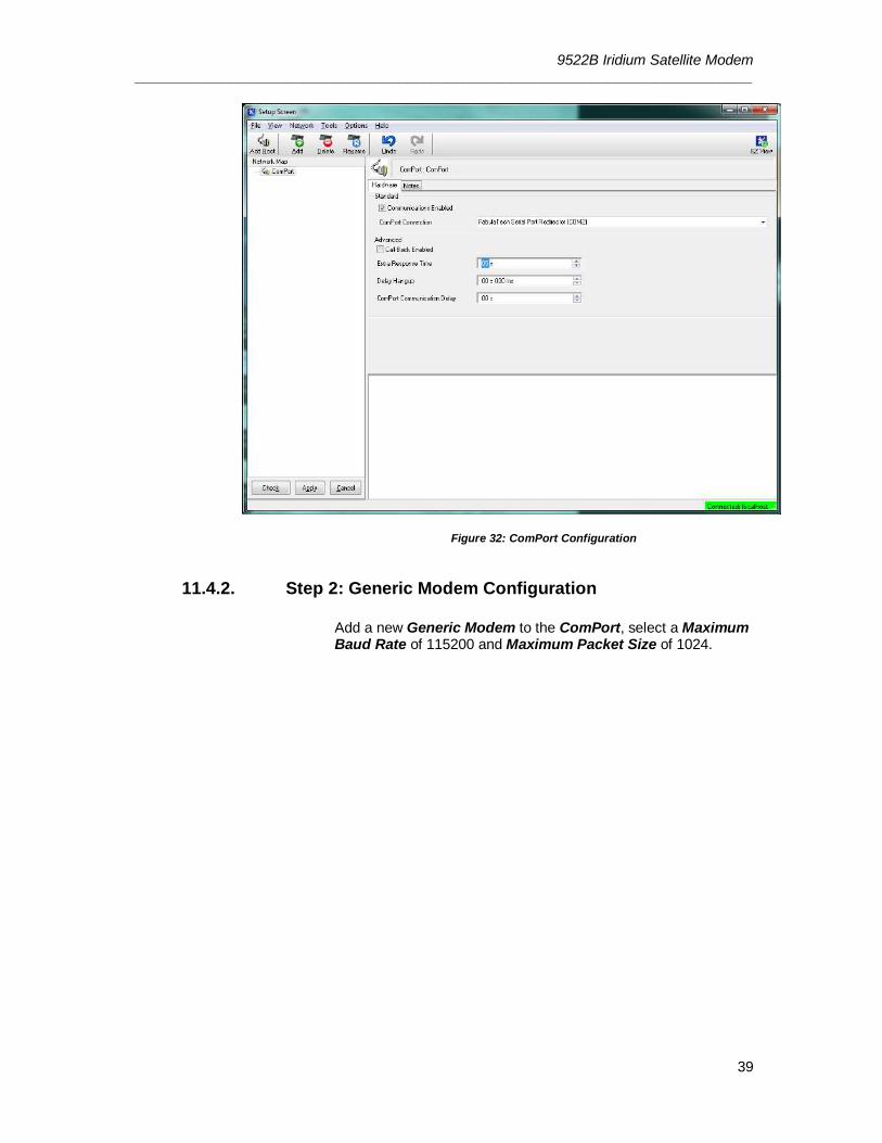
Figure 32: ComPort Configuration
11.4.2. Step 2: Generic Modem Configuration
Add a new Generic Modem to the ComPort, select a Maximum Baud Rate of 115200 and Maximum Packet Size of 1024.

9522B Iridium Satellite Modem _____________________________________________________________________________
40
Figure 33: Generic Modem Configuration
In the Modem tab, add a dial script to instruct the RUDICS system to create a new connection to the remote modem. Use the following script to dial number the number of the modem to be contacted. Be sure to replace the “X…” below with the 12 digit number supplied by your Service Provider.
D2000 T "ATS29=8^M" R "OK" 40000 T "ATS57=9600^M" R "OK" 40000 T "ATDI00XXXXXXXXXXXX^M" R "CONNECT" 40000
Next add an end script to close the connection to the remote modem.
D1200 T "+++" D1200 T "ATH^M"
9522B Iridium Satellite Modem _____________________________________________________________________________
41
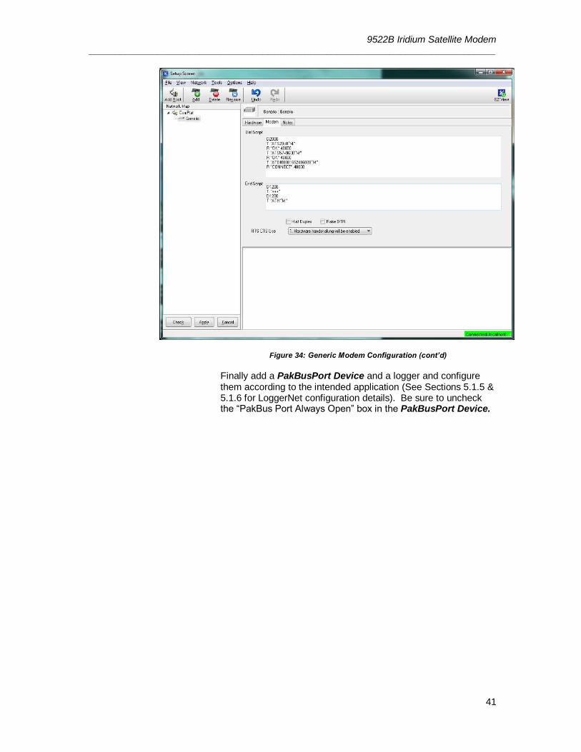
Figure 34: Generic Modem Configuration (cont’d) Finally add a PakBusPort Device and a logger and configure them according to the intended application (See Sections 5.1.5 & 5.1.6 for LoggerNet configuration details). Be sure to uncheck the “PakBus Port Always Open” box in the PakBusPort Device.


Campbell Scienti�c (Canada) Corp. | 14532 131 Avenue NW | Edmonton AB T5L 4X4 | 780.454.2505 | www.campbellsci.caAUSTRALIA | BRAZIL | CANADA | COSTA RICA | FRANCE | GERMANY | SOUTH AFRICA | SPAIN | UNITED KINGDOM | USA