Instruction Manual - Cooper Industries · 2020-01-20 · Instruction Manual FAA L-828 and L-829...
73
DOCUMENT 1207 REVISION A January 12, 2016 Instruction Manual PRO POWER REGULATOR, SMALL FAA L-828 and L-829 Constant Current Regulator Series 82860PES and 82960PRS 4 kW, 7.5 kW, 10 kW, 6.6 Amperes Crouse-Hinds By EATON 1200 Kennedy Road Windsor, CT 06095 Copyright © 2016 Cooper Technologies Company
Transcript of Instruction Manual - Cooper Industries · 2020-01-20 · Instruction Manual FAA L-828 and L-829...

DOCUMENT 1207
REVISION A January 12, 2016
Instruction Manual
PRO POWER REGULATOR, SMALL
FAA L-828 and L-829 Constant Current Regulator Series 82860PES and 82960PRS
4 kW, 7.5 kW, 10 kW, 6.6 Amperes
Crouse-Hinds By EATON 1200 Kennedy Road Windsor, CT 06095
Copyright © 2016 Cooper Technologies Company

DOCUMENT 1207 REV. A
Instruction Manual FAA L-828 and L-829 Constant Current Regulator
Series 82860PES and 82960PRS; 4 kW, 7.5 kW, 10 kW, 6.6 Amperes
ii
Table of Contents 1 Revisions ................................................................................................................................ v 2 Product Warranty ................................................................................................................... vi 3 Safety Notices ...................................................................................................................... vii
3.1 Keep Away from Live Circuits ..................................................................................... vii 3.2 RESUSCITATION ....................................................................................................... vii
4 Safety Symbols ................................................................................................................... viii 4.1 Danger .......................................................................................................................... viii 4.2 Warning ........................................................................................................................ viii 4.3 Caution ......................................................................................................................... viii 4.4 Warning: Notice ........................................................................................................... viii 4.5 Warning : Important ..................................................................................................... viii
5 Recommended Test Equipment and Tools ............................................................................ ix 6 General Information ............................................................................................................... 1
6.1 Introduction ...................................................................................................................... 1 6.2 Applicability ..................................................................................................................... 1 6.3 Equipment Features .......................................................................................................... 1 6.4 Options ............................................................................................................................. 2 6.5 FAA Classification ........................................................................................................... 2 6.6 Electrical Characteristics .................................................................................................. 2 6.7 Physical Characteristics ................................................................................................... 3 6.8 Part Numbers, Input Voltages, Output Load Ratings and Available Options: ................. 4
7 Installation .............................................................................................................................. 5 7.1 Recommended Installation Tools ..................................................................................... 6 7.2 Mechanical Installation .................................................................................................... 6 7.3 Proper Location ................................................................................................................ 6 7.4 Door Latch Operation ...................................................................................................... 6 7.5 Knockouts and Wiring Paths ............................................................................................ 6 7.6 Standard Wiring Knockouts ............................................................................................. 6 7.7 Alternate Grounding Location ......................................................................................... 6 7.8 Lifting and Transport ....................................................................................................... 7 7.9 Stand-alone Installation .................................................................................................... 7 7.10 Stacked Installation .......................................................................................................... 7 7.11 Electrical Installation ..................................................................................................... 14 7.12 Equipment Ground Connection ...................................................................................... 14 7.13 Input Power/Line Connections ....................................................................................... 14

DOCUMENT 1207 REV. A
Instruction Manual FAA L-828 and L-829 Constant Current Regulator
Series 82860PES and 82960PRS; 4 kW, 7.5 kW, 10 kW, 6.6 Amperes
iii
7.14 Input Power/Line Ground Connection ........................................................................... 15 7.15 Output/Load Power Connections ................................................................................... 15 7.16 Remote Control Connections ......................................................................................... 17 7.17 Remote Using Internal Power Supply ............................................................................ 17 7.18 Remote Using External Power Supply ........................................................................... 18 7.19 CCR Configuration ........................................................................................................ 18 7.20 Configuration Dip Switch Settings ................................................................................ 19 7.21 Internal Remote Power Supply Enable .......................................................................... 20 7.22 L-829 Monitor Enable .................................................................................................... 20 7.23 Step Mode Configuration ............................................................................................... 20 7.24 Final Installation Check ................................................................................................. 20
8 Operation .............................................................................................................................. 21 8.1 Local Control Rotary Switch ......................................................................................... 22 8.2 Remote Control .............................................................................................................. 22 8.3 Pro Power Essential Model Option Control ................................................................... 22 8.4 Pro Power Premium Model Touch Pad Control and Display ........................................ 22 8.5 Pro Power Essential Model (Standard) Digital Display ................................................. 22
9 Problem Solving and Maintenance ....................................................................................... 24 9.1 CCR Safety .................................................................................................................... 24 9.2 Maintenance Tools ......................................................................................................... 25 9.3 Periodic Maintenance ..................................................................................................... 25 9.4 Corrective Maintenance ................................................................................................. 26 9.5 Troubleshooting Guide................................................................................................... 27 9.6 Power Supply ................................................................................................................. 27 9.7 Control Board ................................................................................................................. 29 9.8 Control Board Diagnostic Indicators ............................................................................. 29 9.9 MCU (Microprocessor Control Unit) Indicator “D31” .................................................. 31 9.10 24V Remote Indicator “D22” & “D20” ......................................................................... 31 9.11 Contactor Indicator “D34” & “D38” .............................................................................. 31 9.12 24V Indicator “D15” & “D16” ...................................................................................... 31 9.13 Control Board Relay Indicators “D11” to “D18” ........................................................... 31 9.14 Output Current Regulation ............................................................................................. 32 9.15 Remote Control .............................................................................................................. 34 9.16 Recommended Torque Values for CCR Hardware ........................................................ 42 9.17 Recommended CCR Spare Parts .................................................................................... 43 9.18 Major CCR Parts and Locating Figures ......................................................................... 44

DOCUMENT 1207 REV. A
Instruction Manual FAA L-828 and L-829 Constant Current Regulator
Series 82860PES and 82960PRS; 4 kW, 7.5 kW, 10 kW, 6.6 Amperes
iv
10 L-829 Monitor and Option “P”; Use and Display, Pro Power Essential Models ............... 55 10.1 Pro Power Essential L-829 Setup and Calibration ......................................................... 56 10.2 Percent Power Monitor .................................................................................................. 57 10.3 Circuit Power Calibration .............................................................................................. 57 10.4 Lamp Out Monitor ......................................................................................................... 58 10.5 Lamp out settings and Calibration ................................................................................. 58 10.6 Power Calibration .......................................................................................................... 58 10.7 First Lamp threshold ...................................................................................................... 58 10.8 Second Lamp Threshold ................................................................................................ 59 10.9 Lamp out Calibration ..................................................................................................... 59 10.10 L-829 Relay Indicators ................................................................................................... 60 10.11 L-829 Operation ............................................................................................................. 60 10.12 Lamp-out Operation ....................................................................................................... 60 10.13 L-829 Alarms ................................................................................................................. 60 10.14 Option “P” (Input Line Voltage and Input Line Current) Display ................................. 61
11 L-829 Monitor, Digitrac, Megatrac and Option “P”; Use and Display , Pro Power Premium Models (Touch Screen) ................................................................................................................. 62

DOCUMENT 1207 REV. A
Instruction Manual FAA L-828 and L-829 Constant Current Regulator
Series 82860PES and 82960PRS; 4 kW, 7.5 kW, 10 kW, 6.6 Amperes
v
1 Revisions
Revision Number
Issue/Reissue Number Letter Description Checked Approved
A A215-233 Initial release TG/PG/MG/JL/PR/RB
1/12/16

DOCUMENT 1207 REV. A
Instruction Manual FAA L-828 and L-829 Constant Current Regulator
Series 82860PES and 82960PRS; 4 kW, 7.5 kW, 10 kW, 6.6 Amperes
vi
2 Product Warranty Warranty Refer to Eaton’s Crouse-Hinds Airport Lighting Products Terms and Conditions for product specific warranty information.
DOCUMENT 1207 REV. A
Instruction Manual FAA L-828 and L-829 Constant Current Regulator
Series 82860PES and 82960PRS; 4 kW, 7.5 kW, 10 kW, 6.6 Amperes
vii
3 Safety Notices This equipment is normally used or connected to circuits that may employ voltages which are dangerous and may be fatal if accidentally contacted by operating or maintenance personnel. Extreme caution should be exercised when working with this equipment. While practical safety precautions have been incorporated in this equipment, the following rules must be strictly observed:
3.1 Keep Away from Live Circuits Operating and maintenance personnel must at all times observe all safety regulations. Do not perform maintenance on internal components or service with power ON.
DANGER:
DANGER
Lock Out electrical power to the Constant Current Regulator (CCR) at its source before opening the CCR door and attempting servicing. Note, if the CCR is equipped with an integral circuit breaker (Option “B”), power is present at CB1 input terminals even with the circuit breaker in the “off” position. Lock Out electrical power prior to CB1 if entering the CCR cabinet.
3.2 RESUSCITATION Maintenance personnel should familiarize themselves with the technique for resuscitation found in widely published manuals of first aid instruction.

DOCUMENT 1207 REV. A
Instruction Manual FAA L-828 and L-829 Constant Current Regulator
Series 82860PES and 82960PRS; 4 kW, 7.5 kW, 10 kW, 6.6 Amperes
viii
4 Safety Symbols
4.1 Danger
DANGER:
DANGER The hazard or unsafe practice will result in severe injury or death.
4.2 Warning
WARNING:
WARNING The hazard or unsafe practice could result in severe injury or death.
4.3 Caution
CAUTION:
CAUTION The hazard or unsafe practice could result in minor injury.
4.4 Warning: Notice
WARNING:
NOTICE Possibly dangerous situation, goods might be damaged.
4.5 Warning : Important
WARNING:
IMPORTANT Helpful information.

DOCUMENT 1207 REV. A
Instruction Manual FAA L-828 and L-829 Constant Current Regulator
Series 82860PES and 82960PRS; 4 kW, 7.5 kW, 10 kW, 6.6 Amperes
ix
5 Recommended Test Equipment and Tools There is a wide variety of tools and equipment needed to safely and correctly perform airfield lighting equipment installation and maintenance. In addition to the obvious tools (screwdrivers, wrenches, etc.), there is specialized equipment needed to do the job. Multimeter One of the most important pieces of test equipment is the Multimeter. It is used to measure voltages, currents, and resistances. Almost every single maintenance task requires the use of a multimeter at one point or another. A quality meter in good repair and calibration is a must because airfield lighting power distribution equipment produces non-sinusoidal waveforms, traditional average reading meters are inaccurate and have very limited use. Checking or adjusting equipment based upon incorrect current reading may dramatically reduce lamp life and adversely affect power equipment performance. A meter with TRUE RMS measuring capability with a current clamp-on accessory is needed to accurately measure distorted or chopped waveforms. All meter manufacturers offer TRUE RMS measuring meters. The following is a short list of TRUE RMS Multimeters from Fluke:
Manufacturer Model Number
Fluke 287 Our recommended multimeter is the Fluke 287 with the Fluke I800 current clamp accessory. Refer to the equipment manufacturer’s manuals for the proper use, maintenance and calibration (if necessary) of all meters. Voltage Detector, Fluke P/N 1AC-A1-II or equal. The Fluke model detects voltages ranging from 90 to 1,000 VAC. 3/8 inch square drive sockets, extensions and ratchet, sizes 5/16/ 7/16, 9/16 and 1/2. We recommend you buy a set of Paramount Sockets/Extensions/Ratchets that come as a complete set for both 1/4 and 3/8 drive ratchets and associated extensions, standard and deep sockets, fractional and metric size sockets, P/N PAR-TK103-B or equal Ratcheting combination wrenches, sizes 11/32, 3/8, 7/16 and 3/4. We recommend you buy a set of Paramount Ratcheting Combination Wrenches that come as a complete set in fractional sizes 5/16 to 1 inch, P/N PAR-13PCBTRSET or equal Hex Keys, sizes .050, 3/16 and 1/4. We recommend that you buy a complete set of Bondhus Hex Keys, .050, 1/16 to 3/8, P/N 10937 or equal Screwdriver, Phillips, #1, Proto P/N 9482 or equal Screwdriver, straight blade, 3/32, Wera P/N 05118008004 or equal Screwdriver, straight blade, 1/8, Stanley P/N 66-112 or equal

DOCUMENT 1207 REV. A
Instruction Manual FAA L-828 and L-829 Constant Current Regulator
Series 82860PES and 82960PRS; 4 kW, 7.5 kW, 10 kW, 6.6 Amperes
x
Screwdriver, straight blade, 3/16, Proto P/N 9403 or equal Screwdriver, straight blade, 5/16, Proto P/N 9406 or equal A calibrated adjustable torque screwdriver. Sturtevant Richmont P/N 810568 (comes with bits [hex, slotted, Torx, Phillips, sq. recess, bit holder, socket adapter], case and certificate of calibration), range 2 to 36 in-lbs/0.2 to 4 Nm or equal. Note, never loosen screws with a torque screwdriver. A calibrated torque wrench (micrometer adjustable solid audible/tactile “click” impulse when torque value attained with an accuracy of +/- 4. Sturtevant Richmont P/N 810751, range 30 to 150 in-lbs or equal. Certificate of calibration included with suggested torque wrenches. Note, never loosen bolts with a torque wrench. A calibrated torque wrench (micrometer adjustable solid audible/tactile “click” impulse when torque value attained with an accuracy of +/- 4. Sturtevant Richmont P/N 810748, range 100 to 600 in-lbs or equal. Certificate of calibration included with suggested torque wrenches. Note, never loosen bolts with a torque wrench. Hand tools indicated above can be purchased from MSC Industrial Supply Co. ( http://www.mscdirect.com/ ). A grounded ESD Wrist Strap when working on circuit cards. ESD Wrist Straps, also known as anti-static Wrist Straps, are used to prevent electrostatic discharge (ESD) by safely grounding a person working with electronic equipment or at an electronic assembly facility. It consists of a band of fabric with fine conductive fibers woven into it. The fibers are usually made of carbon-filled rubber, and the strap is bound with a stainless steel clasp or plate. ESD Products brand ( http://www.esdproduct.com/esd_wrist_straps.php ) or equal. Lock-out/Tag-out accessories as required. A vacuum cleaner for cleaning debris from installation and during Regulator maintenance. Avoid compressed air since it can force debris into places where damage can occur. Tools and connectors/crimpers (as required) to install/bend/cut conduit, pliers tighten conduit locknut fittings and cable from utility power source to the Regulator line connections at initial installation. Airfield FAA L-824 cable and FAA L-823 primary connector kits to make connections between Regulator output load and airfield circuit at initial installation. Use an FAA L-823 primary connector kit pin crimper that the O.E.M. recommends for their kits. A cable penciller for preparing ends of FAA L-824 cable for connector kits, Crouse-Hinds Airport Lighting P/N 10036-36.

DOCUMENT 1207 REV. A
Instruction Manual FAA L-828 and L-829 Constant Current Regulator
Series 82860PES and 82960PRS; 4 kW, 7.5 kW, 10 kW, 6.6 Amperes
xi
Cable/wire (recommend using #24-20 AWG) to connect Regulator remote control terminal block (will accept #24-12) to a control system if remote control is to be utilized.

DOCUMENT 1207 REV. A
Instruction Manual FAA L-828 and L-829 Constant Current Regulator
Series 82860PES and 82960PRS; 4 kW, 7.5 kW, 10 kW, 6.6 Amperes
1
6 General Information
6.1 Introduction The Constant Current Regulator (CCR) is a power supply designed for precision operation of airfield lighting. This instruction manual provides information for installing and maintaining FAA Type L-828 and L-829 Constant Current Regulators manufactured by Eaton, Crouse-Hinds, Airport Lighting Products, Windsor, Connecticut 06095, U.S.A.
6.2 Applicability Only 4kW, 7.5kW, and 10kW CCRs bearing Eaton, Crouse-Hinds catalog number series 82860PES or 82960PRS, are covered by this manual. Refer to section 6.8 for complete part number information. Specific parts and wiring unique to option “CA” are also provided in this manual, as indicated in text or figures.
6.3 Equipment Features
• Output current is regulated within FAA specifications at any rated load and for line voltages from +10% to –5% of nominal.
• 1, 3 or 5 discrete brightness steps conform to FAA standards with other brightness steps available
for a wider range of discrete brightness steps applications.
• The CCR may be controlled both locally and from a remote location.
• Ferroresonant design provides a clean sine wave output current which reduces electrical noise and circuit crosstalk.
• Protective monitoring circuits are provided to shut down the regulator when load is above or
below the specified range.
• A front panel digital display provides an RMS ammeter reading of output current and indication of various faults and warnings.
• L-829 models provide additional monitoring and warnings when the connected lighting circuit
has lamp failures or other faults.
• The CCR may be connected directly to an FAA approved load switching device.

DOCUMENT 1207 REV. A
Instruction Manual FAA L-828 and L-829 Constant Current Regulator
Series 82860PES and 82960PRS; 4 kW, 7.5 kW, 10 kW, 6.6 Amperes
2
6.4 Options This CCR can be factory supplied with various options. See section 6.8 for a list of options.
6.5 FAA Classification Specification: Constant Current Regulator manufactured and qualified to FAA Advisory Circular
150/5345-10 (latest) Type: L-828 and L-829 Regulator Class: 1 – 6.6 amperes output current Style: 1 – 3 Brightness Steps: 4.8, 5.5, 6.6 amperes
2 – 5 Brightness Steps: 2.8, 3.4, 4.1, 5.2, 6.6 amperes Ratings: Sizes – 4kW, 7.5kW, 10kW
Voltages – 208VAC 60 Hz, 220VAC 60Hz, 240VAC 60Hz, 347VAC 60Hz, 380VAC 60Hz, 400VAC 60HZ, 480 VAC 60Hz
6.6 Electrical Characteristics Table 1 lists the minimum recommended circuit breaker or fuse ratings and maximum output voltage for the various CCR power and voltage ratings. The listed line currents are 125% of the rated input current. If exact breaker or fuse sizes are not available for a given configuration, chose an available device with the next higher rating above the minimum recommended.
CCR Size Minimum Recommended Breaker/Fuse Rating (Amps RMS) Maximum Output
Voltage Load at 6.6A
208V 220V 240V 347V 380V 400V 480V 4 kW 29 28 25 18 17 15 13 606.1
7.5 kW 54 50 47 33 30 28 24 1136.4 10 kW 72 68 62 43 39 38 32 1515.2
TABLE 1
WARNING:
NOTICE The CCR load (VA) shall not exceed the rated load (kW) on the name plate, at installation and subsequent load changes.

DOCUMENT 1207 REV. A
Instruction Manual FAA L-828 and L-829 Constant Current Regulator
Series 82860PES and 82960PRS; 4 kW, 7.5 kW, 10 kW, 6.6 Amperes
3
WARNING:
WARNING Running the CCR while overloaded may cause damage to the CCR.
6.7 Physical Characteristics Dimensions: Refer to Outline Drawings, Figures 2 – 5
Weight 4 kW – 490 lbs.
7.5kW – 581 lbs. 10kW – 711 lbs.
Mechanical: The CCR has a vented steel enclosure painted blue and the door painted black. Premium models have a brushed aluminum control panel. The enclosure is load-bearing which allows stacking of CCRs (up to 3 high).
Environmental: Temperature: -40 degrees C to +55 degrees C (-40 degrees F to +131 degrees F)
Relative Humidity: 10 percent to 95 percent
Altitude: Zero to 6,600 feet (2000 m)

DOCUMENT 1207 REV. A
Instruction Manual FAA L-828 and L-829 Constant Current Regulator
Series 82860PES and 82960PRS; 4 kW, 7.5 kW, 10 kW, 6.6 Amperes
4
6.8 Part Numbers, Input Voltages, Output Load Ratings and Available Options:
DOCUMENT 1207 REV. A
Instruction Manual FAA L-828 and L-829 Constant Current Regulator
Series 82860PES and 82960PRS; 4 kW, 7.5 kW, 10 kW, 6.6 Amperes
5
7 Installation
WARNING:
IMPORTANT Maintenance and troubleshooting on Constant Current Regulator (CCRs) should only be performed by qualified electricians with a working knowledge of airfield lighting series circuit power.
WARNING:
NOTICE Read these instruction before attempting installation. Improper installation can damage the CCR and may void the warranty.
WARNING:
IMPORTANT User and installer should review FAA AC 150/5340-30 (latest), Design and Installation Details for Airport Visual Aids regarding CCRs use, Standby Power and Vaults.
WARNING:
IMPORTANT If equipment fails to perform properly at any step of this procedure, consult the maintenance and troubleshooting guides in Section 9. And if L-829, the set-up procedure in Section 10 or 11.

DOCUMENT 1207 REV. A
Instruction Manual FAA L-828 and L-829 Constant Current Regulator
Series 82860PES and 82960PRS; 4 kW, 7.5 kW, 10 kW, 6.6 Amperes
6
7.1 Recommended Installation Tools See section 5.
7.2 Mechanical Installation Unpack the Constant Current Regulator, and check for any shipping damage.
7.3 Proper Location The regulator is designed for indoor locations meeting the environment specified in section 6.7. The area should be clean and dry, protected from rain, snow, dust, etc., and have adequate ventilation. The equipment should be accessible to qualified personnel only.
7.4 Door Latch Operation The door latch operates by depressing the top of it and lifting its bottom, rotating clockwise (CW). Note, the keys for the latch lock are cable tied to its mechanism on the interior. These keys are intended to be possessed by the end user. Door latch should be locked during normal operation of CCR.
7.5 Knockouts and Wiring Paths It may be necessary or preferable to remove wiring knockouts before the CCR is installed into position. Plan wiring paths and remove or enlarge knockouts before moving the CCR into position where access may be difficult.
WARNING:
NOTICE Be sure to avoid getting debris/metal chips inside the interior of the CCR if enlarging knockout holes. Metal chips may void warranty.
7.6 Standard Wiring Knockouts There are 6 knockout locations (3 top, 3 bottom) intended for input, output, and control wiring. In stacked configurations, the top and bottom knockouts may need to be enlarged in the field to accommodate wiring from multiple CCRs. The existing knockouts may be enlarged to a maximum 1 ½ (trade size). Equipment ground connection is located on left side of the cabinet exterior. See Figures 1 and 3 for ground and knockout locations.
7.7 Alternate Grounding Location Installations where CCRs are placed in close proximity to other CCRs, walls, or other equipment, the equipment ground connection on the left side exterior may not be accessible, and must be removed by the installer. A knockout location and alternative ground connection point is provided for these situations. The knockout is located at the rear of the cabinet as shown in Figure 4 and the alternate ground connection is located at the left interior of the cabinet. If an alternate ground location is used with option

DOCUMENT 1207 REV. A
Instruction Manual FAA L-828 and L-829 Constant Current Regulator
Series 82860PES and 82960PRS; 4 kW, 7.5 kW, 10 kW, 6.6 Amperes
7
“CA”, attach equipment ground lead to grounding bar by replacing the lead that goes from the bonding bar to the exterior ground lug.
7.8 Lifting and Transport Move CCR to its installation location. There is forklift clearance of 2” underneath the unit. Eye bolts are also provided for lifting and moving the CCR. The regulator should be close to its intended installation location before lifting.
CAUTION:
CAUTION The CCR is extremely heavy and must be moved only by qualified personnel with proper equipment.
7.9 Stand-alone Installation Install the CCR on a flat, solid surface with the back of the unit at least 1 foot away from walls or other obstructions. This allows clearance for the rear ventilation holes.
7.10 Stacked Installation Refer to Figure 5 for stacked information. Before stacking CCRs, it may be necessary to enlarge the entry and exit holes for wiring.
WARNING:
NOTICE Be sure to avoid getting debris/metal chips inside the interior of the CCR if enlarging knockout holes.
1) Install the lower CCR on a flat, solid surface as in a stand-alone installation with the back of the unit at least 1 foot away from walls or other obstructions.

DOCUMENT 1207 REV. A
Instruction Manual FAA L-828 and L-829 Constant Current Regulator
Series 82860PES and 82960PRS; 4 kW, 7.5 kW, 10 kW, 6.6 Amperes
8
WARNING:
WARNING The CCR with the highest kW rating must be located in the lowest position if stacking CCRs. This is due to the CCR weight, to avoid a top heavy stacked line-up.
2) Fasten the lower CCR to the floor through the mounting holes at each bottom corner. The bottom
mounting hole locations are for 3/8 diameter hardware at the same dimensions as the (4) CCR cover bolts.
3) Remove the bolts that hold the top cover of the lower CCR.
4) Lift the upper CCR into position and align its bottom mounting holes at each corner with the 4 bolt
holes in the top cover of the lower CCR.
WARNING:
WARNING
Do not use eye bolts for lifting multiple attached CCRs at once. Eye bolts are rated to support a single CCR only. If an eyebolt is damaged, remove and destroy by cutting through the eye. Sling angles should not exceed angles indicated on Figures 1 and 2.
WARNING:
WARNING
Be sure to safely support the entire weight of the CCR to be secured to the one beneath it. Painted surfaces are slippery, and a CCR stacked on top of another CCR could slip off before it is properly secured to the CCR under it.
5) Install the bolts that were removed in step 3 through the bottom mounting holes of the upper CCR and
into the top bolt holes of the lower CCR and tighten.
6) Repeat for CCR at next level (maximum of 3 levels).

DOCUMENT 1207 REV. A
Instruction Manual FAA L-828 and L-829 Constant Current Regulator
Series 82860PES and 82960PRS; 4 kW, 7.5 kW, 10 kW, 6.6 Amperes
9
FIGURE 1 Height and Width Dimensions
LOCALCONTROLSWITCH
1
2
3
45
OFFREMOTE
OPTIONCONTROL SWITCH

DOCUMENT 1207 REV. A
Instruction Manual FAA L-828 and L-829 Constant Current Regulator
Series 82860PES and 82960PRS; 4 kW, 7.5 kW, 10 kW, 6.6 Amperes
10
FIGURE 2
Depth Dimension

DOCUMENT 1207 REV. A
Instruction Manual FAA L-828 and L-829 Constant Current Regulator
Series 82860PES and 82960PRS; 4 kW, 7.5 kW, 10 kW, 6.6 Amperes
11
FIGURE 3
Knockout Locations, Top and Bottom of Cabinet

DOCUMENT 1207 REV. A
Instruction Manual FAA L-828 and L-829 Constant Current Regulator
Series 82860PES and 82960PRS; 4 kW, 7.5 kW, 10 kW, 6.6 Amperes
12
FIGURE 4
Knockout Location, Alternate Ground Entrance Location

DOCUMENT 1207 REV. A
Instruction Manual FAA L-828 and L-829 Constant Current Regulator
Series 82860PES and 82960PRS; 4 kW, 7.5 kW, 10 kW, 6.6 Amperes
13
FIGURE 5 Stacked CCR Installation
LOCALCONTROLSWITCH
1
2
3
45
OFFREMOTE
OPTIONCONTROL SWITCH
LOCALCONTROLSWITCH
1
2
3
45
OFFREMOTE
OPTIONCONTROL SWITCH
LOCALCONTROLSWITCH
1
2
3
45
OFFREMOTE
OPTIONCONTROL SWITCH

DOCUMENT 1207 REV. A
Instruction Manual FAA L-828 and L-829 Constant Current Regulator
Series 82860PES and 82960PRS; 4 kW, 7.5 kW, 10 kW, 6.6 Amperes
14
7.11 Electrical Installation
DANGER:
DANGER
Lock Out electrical power going to the CCR at the source prior to utility power wiring that will be installed into the CCR. Note, if the CCR is equipped with an integral circuit breaker (Option “B”), power is present at CB1 (integral input circuit breaker) input terminals even with the circuit breaker in the “off” position. Lock Out electrical power prior to CB1 if entering the CCR cabinet after initial electrical installation.
7.12 Equipment Ground Connection Connect the equipment ground conductor (this is not the input line/utility power ground lead) to the equipment ground terminal on the cabinet left side exterior lower front. Depending on the placement of the CCR, a ground connection is provided on the left side interior as an alternate, see section 7.7. The ground lead should be copper and the same gauge or larger than the line/utility power ground lead gauge. Torque the slotted head screw on this lug to 20 in-lbs if #14-10 AWG, 25 in-lbs if #8-6 AWG and 35 in-lbs if #4 AWG.
WARNING:
Notice Do not connect a counterpoise system to the equipment ground terminal or any CCR or other CCR grounding locations.
7.13 Input Power/Line Connections Verify that the line voltage is the same as the regulator nameplate voltage rating.
WARNING:
Notice Connection to the incorrect line voltage may void the warranty.
Connect the line utility power voltage leads (line and neutral) to the line side box terminals (one lead per box lug) of the main contactor K1 and torque the box lug screws to the value indicated on the K1 part label. See Figure 6 for line lead K1 connection points. If option “B” is installed, connect the line voltage leads to CB1 input/line box terminals. Torque values for CB1 line gauge sizes on front face of circuit breaker. If option “P” (Line Voltage and Current Monitoring) is installed, be sure to insert the utility
DOCUMENT 1207 REV. A
Instruction Manual FAA L-828 and L-829 Constant Current Regulator
Series 82860PES and 82960PRS; 4 kW, 7.5 kW, 10 kW, 6.6 Amperes
15
power voltage black lead only through the center of T7 donut transformer before attaching to K1. If option “B” is installed, the utility black voltage line lead will terminate at CB1, and wire assembly 26A is already present through T7 center to K1. See Figure 23.
7.14 Input Power/Line Ground Connection Connect the line utility power ground lead to the INPUT GND box terminal located on the component panel. See Figure 6 for ground lead connection point. Torque the slotted head screw on this lug to 20 in-lbs if #14-10 AWG, 25 in-lbs if #8-6 AWG and 35 in-lbs if #4 AWG. If option “B” is installed, connect the line utility ground lead to CB1 ground box terminal lug located on the CB1 mounting bracket.
7.15 Output/Load Power Connections Connect the airfield series load leads for the circuit the be powered by the CCR to the stud connections (3/8) on the output lighting arrestors, LA2 and LA3 located under their plastic caps. Be careful not to loosen or damage other connections on the same studs. Re-install plastic caps (you may need to enlarge the wire exit slot) after connecting only a single airfield series lead on each lightening arrestor. See Figure 6 for LA2 and LA3 locations. If CCR has option “S” (S-1 Cutout) installed, than the airfield series load leads will connect to box lugs located on the top side of the installed S-1 cutout box, only a single airfield series load lead to each box lug. If option “M” (Megatrac) installed, a single airfield series load lead must be inserted through to center of the Megatrac current sensing transformer mounted over one of the S-1 Cutout output box lug access holes in housing.
CAUTION:
CAUTION Do not megger test the series lighting load while it is connected to the CCR.
WARNING:
IMPORTANT
Option “S”, S-1 Cutout will aid in troubleshooting the CCR by shorting the airfield load connections together, and also shorting the CCR output load side together, as the shorted output series CCR can be tested in a shorted load to determine if a problem exists in the CCR, or if the problem is in the series airfield circuit. Removing the S-1 cutout handle will ensure that no electrical energy produced by the CCR will enter the airfield circuit connected to the S-1 cutout. An airfield series circuit may have electrical energy induced on to it by adjacent energized circuits or by direct contact with energized circuits in a casualty condition. Maintenance personal should always check for Current and Voltage present on airfield series circuit prior to handling the circuit directly with appropriate measuring equipment/means. Airfield series circuits will often have stored a static charge on them following energized operation. If

DOCUMENT 1207 REV. A
Instruction Manual FAA L-828 and L-829 Constant Current Regulator
Series 82860PES and 82960PRS; 4 kW, 7.5 kW, 10 kW, 6.6 Amperes
16
detected, static potential charges can be discharged by grounding the circuit. Input power to the CCR should be locked out before removing or inserting an S-1 cutout handle.
FIGURE 6
Input/Line and Output/Load Power Connections
T1LA3
LA2
LA2 OUTPUT
K2
LA1
T3
E1
T4
TB2
T7 K1
INPUT
INPUTGND
T2
T9
LA3 OUTPUT

DOCUMENT 1207 REV. A
Instruction Manual FAA L-828 and L-829 Constant Current Regulator
Series 82860PES and 82960PRS; 4 kW, 7.5 kW, 10 kW, 6.6 Amperes
17
7.16 Remote Control Connections
WARNING:
NOTICE Incorrect wiring can cause a malfunction or damage to the control system and may void the equipment warranty. Recheck these connections before operating.
Connect remote control lines to terminal block TB1 located on the 34229 Control Board mounted to the door interior. This terminal block accepts #24-12 AWG, but the use of #24-20 AWG is recommended. The regulator is shipped configured for internally supplied remote control power.
7.17 Remote Using Internal Power Supply For 120VAC remote operation using internal remote power, a jumper is placed on the Control Board between terminals E1 and E2 near TB1 where the remote wiring is connected. See Figure 13B, left side edge between the two terminal blocks. The internal remote power at the CCI terminal is connected from the CCR to the remote location and returned through the remote operation switches to each of the remote terminals at the CCR. Note, if option “V” (Internally Supplied 24 VDC) is specified, the remote operation using internal remote power will be 24 VDC.
WARNING:
NOTICE Do not connect remote neutral (N) in this configuration.
Add a wire jumper between the CC and B1 terminals. Refer to Figure 7 below.
FIGURE 7 Remote Control Using Internal Power

DOCUMENT 1207 REV. A
Instruction Manual FAA L-828 and L-829 Constant Current Regulator
Series 82860PES and 82960PRS; 4 kW, 7.5 kW, 10 kW, 6.6 Amperes
18
7.18 Remote Using External Power Supply For remote operation using external remote power, a jumper is placed on the Control Board between terminals E2 and E3 near TB1 where the remote wiring is connected. Run the remote neutral at the N terminal from the CCR to the remote location. See Figure 13B, left side edge between the two terminal blocks.
WARNING:
NOTICE Do not connect internal remote power (CCI) in this configuration.
Remote neutral from the CCR is connected to the neutral or ground of the external remote power source. The remote power source is returned through the remote operation switches to each of the remote terminals at the CCR. Add a wire jumper between the CC and B1 terminals. Refer to Figure 8 below.
FIGURE 8 Remote Control Using External Power
7.19 CCR Configuration The CCR is shipped with its configuration as specified when it was ordered, but may need to be reconfigured for different application (number of steps, for example). Configuration is controlled by the SW1 dip switch on the control board shown in Figure 9.

DOCUMENT 1207 REV. A
Instruction Manual FAA L-828 and L-829 Constant Current Regulator
Series 82860PES and 82960PRS; 4 kW, 7.5 kW, 10 kW, 6.6 Amperes
19
FIGURE 9 Configuration Dip Switch
7.20 Configuration Dip Switch Settings Table 2 below shows the settings configured by control board switch SW1.
CAUTION:
CAUTION Do not change current output switch setting. 10 kW and smaller CCRs are only available with 6.6A output current. Do not change undocumented switch settings.
SW1 POSITION Function 1 2 3 4 5 6 7 8 Remote Mode Standard x x x OFF x x x x Remote Mode ALCMS x x x ON x x x x L829 Monitor Enabled x x x x ON x x x L829 Monitor Disabled x x x x OFF x x x 1 Step Mode 5.5A OFF ON x x x x x x 3 Step Mode OFF OFF x x x x x x 5 Step Mode ON OFF x x x x x x Custom Step Mode ON ON x x x x x x 6.6A Current Output x x OFF x x x x x 20A Current output x x ON x x x x x
“x” = position (on/off) is of no importance TABLE 2
Configuration Dip Switch Settings

DOCUMENT 1207 REV. A
Instruction Manual FAA L-828 and L-829 Constant Current Regulator
Series 82860PES and 82960PRS; 4 kW, 7.5 kW, 10 kW, 6.6 Amperes
20
7.21 Internal Remote Power Supply Enable If the CCR will use an external power source for the remote control, the internal remote power supply is disabled. If internal remote power is needed, this switch may be changed to activate internal remote power through remote contact closures.
7.22 L-829 Monitor Enable L-829 models are configured with L-829 monitoring active. This monitoring can be disabled by its configuration switch.
WARNING:
NOTICE
A potential transformer (T4) rated for the applicable CCR must be installed internally to the CCR for L-829 monitoring to function. If T4 is not present and L-829 enabled at control board SW1 switch, false readings and alarms will be present. Note, no damage to equipment will occur.
7.23 Step Mode Configuration There are 4 brightness step configurations. If the CCR must provide a different number of brightness steps than originally configured, change the SW1 switch settings on the control board as shown in Table 2. Custom step mode is used for special applications and Crouse-Hinds Airport Lighting would need to be contacted prior to purchase for feasibility or to provide special instructions and/or factory set-up. You will also need to change the Brightness Control Switch plate. The 3 and 5 brightness control step plate is reversible by removing the (4) re-useable push pins in the plate corners by pushing on the pin shaft ends on the interior side of the door. The 1 step/8 step brightness control plate is also reversible. The brightness control rotary switch stops will also need to be changed, removing it from the door and reinstalling it after its stop tabs have been repositioned per the wiring diagram.
7.24 Final Installation Check Check that all cables and wiring are dressed within the cabinet. Reinstall all covers.
DOCUMENT 1207 REV. A
Instruction Manual FAA L-828 and L-829 Constant Current Regulator
Series 82860PES and 82960PRS; 4 kW, 7.5 kW, 10 kW, 6.6 Amperes
21
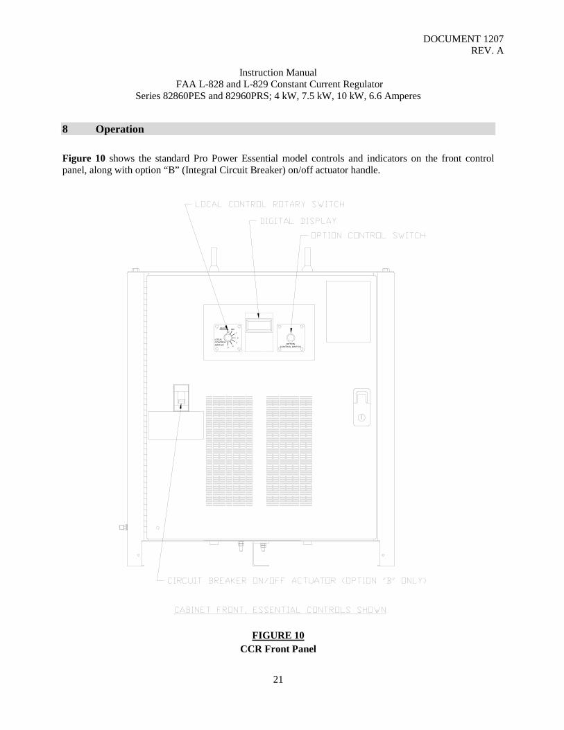
8 Operation Figure 10 shows the standard Pro Power Essential model controls and indicators on the front control panel, along with option “B” (Integral Circuit Breaker) on/off actuator handle.
FIGURE 10
CCR Front Panel
LOCALCONTROLSWITCH
1
2
3
45
OFFREMOTE
OPTIONCONTROL SWITCH

DOCUMENT 1207 REV. A
Instruction Manual FAA L-828 and L-829 Constant Current Regulator
Series 82860PES and 82960PRS; 4 kW, 7.5 kW, 10 kW, 6.6 Amperes
22
8.1 Local Control Rotary Switch The local control rotary switch is used to command the CCR into various brightness steps from the front panel or to place it into remote control mode to accept remote commands. Rotating the switch clockwise from “OFF” to “1” will cause the CCR to turn on and produce output current corresponding to B1 (or B10 for 3 step CCRs). Continuing to rotate local control switch clockwise will increase the CCR output current according to the specified brightness step. Rotating the local control switch counterclockwise from “OFF” to “REMOTE” will place the CCR in remote control mode. The switch must be in this position to accept remote commands from a wired remote control or computer control system (ALCMS).
8.2 Remote Control Please refer to section 7.16 and 7.17 for proper wiring of the remote control. As mentioned above, the local control switch must be in the “REMOTE” position for the remote control to function. When power is applied to remote inputs CC/B1, the CCR will turn on and automatically operate at step B1/B10. If power is simultaneously applied to remote inputs B2-B5 (B30-B100), then the CCR will operate at the highest step corresponding to the remote input pin that has power applied. For example, if power is applied to remote input CC/B1 and B2-B5, the CCR will operate at step B5 and if power is applied to remote input B2-B3, the CCR will operate at step B3. If power is removed from CC/B1, the CCR will turn off, overriding all other signals.
8.3 Pro Power Essential Model Option Control The Pro Power Essential option control is a freely rotating knob with push-button functionality when the knob is pressed inward. This control is used for both service diagnostics and to control various CCR options. On L-829 models, this control is used for data entry and activation of L-829 monitoring features. This control is also used to display line voltage and line current when option “P” is installed. Please refer to section 10 for information on Pro Power Essential L-829 monitoring functions.
8.4 Pro Power Premium Model Touch Pad Control and Display The Pro Power Premium touch pad is scrolled upwards or downwards via its touch capability to access menus to input data for a particular function or installed option. This touch pad is also used for service diagnostics and to monitor various CCR options parameters as well as standard current output. On L-829 models, this control is used for data entry and activation of L-829 monitoring features. It is also used for optional Digitrac (option “D”) [Digitrac is for use with Crouse-Hinds Airport Lighting FAA L-890 ALCMS (Airfield Lighting Control and Monitoring Systems, FAA L-890) systems] and Megatrac (Option “M”) [Megatrac is used to automatically measure insulation resistance on the airfield series lighting circuit cable attached to the CCR] to input and display data for these options. When option “P” is installed, it also will display line voltage and line current. Please refer to section 11 for information on Pro Power Premium L-829 monitoring functions and options “D” and “M”.
8.5 Pro Power Essential Model (Standard) Digital Display When the CCR is not producing output current, the digital display will read “OFF”. During normal operation at any brightness level, the digital display functions as a True RMS ammeter, displaying the regulator load current. Other conditions such as faults or information may appear on the digital display. Multiple errors or information will be displayed in order with each item remaining on the display for

DOCUMENT 1207 REV. A
Instruction Manual FAA L-828 and L-829 Constant Current Regulator
Series 82860PES and 82960PRS; 4 kW, 7.5 kW, 10 kW, 6.6 Amperes
23
approximately 3 seconds. The table below lists the standard display functions. Other information may be displayed on L-829 models with monitoring enabled. Please refer to section 10 for information on L-829 monitoring functions.
FIGURE 11 Standard Digital Display Messages
MESSAGE DESCRIPTION
Program Level: When power is applied, this message will be displayed for 1 second. The number “1.0” will be replaced with the
current level of the control board firmware.
Off: the CCR is operating normally but is not producing output current. This will be displayed if the local rotary switch is in the “OFF” position or in “REMOTE” when the CCR is not commanded to a brightness step.
Ammeter: the CCR is operating normally and producing output current. The number displayed will reflect the RMS value of the load current. This is displayed when the local rotary switch is in position “1” or above or in “REMOTE” when the CCR is commanded to a brightness step.
Step Error: The CCR is unable to produce the output current commanded by the user. See section TBD on protection problems.
Over Current Protection: The regulator has tripped off-line due to an over current condition. See section TBD on protection problems.
Open Circuit: The regulator has tripped off-line due to an open circuit (low output current) condition. See section TBD on protection problems.

DOCUMENT 1207 REV. A
Instruction Manual FAA L-828 and L-829 Constant Current Regulator
Series 82860PES and 82960PRS; 4 kW, 7.5 kW, 10 kW, 6.6 Amperes
24
9 Problem Solving and Maintenance
9.1 CCR Safety
DANGER:
DANGER
Lock Out electrical power to the CCR at its source before opening the CCR door and attempting servicing. Note, if the CCR is equipped with an integral circuit breaker (Option “B”), power is present at CB1 input terminals even with the circuit breaker in the “off” position. Lock Out electrical power prior to CB1 if entering the CCR cabinet.
DANGER:
DANGER
Energy may be stored in CCR “C1” capacitors. Capacitors discharge automatically during normal operation. However the “C1” capacitors should be assumed to be charges until proven safe to handle. Charged “C1” capacitors can be detected by measuring across the capacitor terminals with a DC voltmeter. Charged “C1” capacitors can be discharged by placing a 10 K Ohm, 5 Watt resistor across the capacitors terminals until the charge is dissipated.
DANGER:
DANGER
CCRs utilizing remote control wiring may have power present on the remote line coming from an external source. Check for voltage on the remote control lines, and if present lock out at its source.
DANGER:
DANGER
Airfield series circuits may be energized by other sources. Check for the presence of voltage between CCR output/load terminals and from output terminals to ground before working on airfield series circuit.

DOCUMENT 1207 REV. A
Instruction Manual FAA L-828 and L-829 Constant Current Regulator
Series 82860PES and 82960PRS; 4 kW, 7.5 kW, 10 kW, 6.6 Amperes
25
WARNING:
IMPORTANT Maintenance and troubleshooting on Constant Current Regulator (CCRs) should only be performed by qualified electricians with a working knowledge of airfield lighting series circuit power.
DANGER:
DANGER
Never use a Video Borescope Probe on an energized CCR. Lock Out electrical power to the Constant Current Regulator (CCR) at its source before opening the CCR door and attempting servicing or inspections.
9.2 Maintenance Tools See section 5 for a list of recommended tools.
9.3 Periodic Maintenance The CCR (Constant Current Regulator) should be inspected periodically as shown below:
6 Month Interval
Procedure
1. Remove main power from the CCR and lock out.
2. Open the front door. Check that no voltage is present on remote control lines or at output/load terminals using a voltage detector to verify if AC voltage is present. Verify no DC voltage on capacitors. Discharge as necessary, see section 9.1.
3. Check all wiring connections for loose connections and tighten as necessary.
See Tables 3 and 4 for hardware torque values, and sections 7.12 to 7.15 for input/line, input/ground, equipment ground and output/load torque values.
4. Check for broken or damaged wires and parts.
5. Remove dust build – up with a vacuum.

DOCUMENT 1207 REV. A
Instruction Manual FAA L-828 and L-829 Constant Current Regulator
Series 82860PES and 82960PRS; 4 kW, 7.5 kW, 10 kW, 6.6 Amperes
26
6. Inspect housing for rust or chipped paint. Clean and touch up with paint as required. Paint used on the cabinet is electrostatically applied powder coat paint. You will only be able to apply liquid paint that you must purchase from your local hardware store. Approximate blue color match; Pantone 541C. Approximate black color match; Pantone 6C.
7. Apply current clamp to either wire #T1-X1 at LA2 or wire #T3-H2 at LA3.
Close door. Note, there are slots at the bottom of the door on each side to allow door to be closed with meter cables attached.
8. Connect your current clamp leads to your calibrated true Root Mean Square (RMS) digital multi-meter. Restore main power to the CCR. Operate the CCR at all brightness steps, first by local control, then by remote control. Check for proper load current values with your calibrated true RMS multi-meter.
9. Remove main power from the CCR and lock out. Open door and remove
current clamp. Close door and restore power.
WARNING:
NOTICE
Maintenance personal should reference any requirements/ periodic inspections and reports required by FAA AC 150/5340-26 (latest) , Maintenance of Airport Visual Aid Facilities regarding CCRs and Lighting Vaults.
9.4 Corrective Maintenance Corrective maintenance is required when the regulator does not work properly. This may require the replacement of parts or subassemblies. The removal and replacement method should be obvious to qualified personnel. The control assembly contains parts which can be replaced in the field by a service person. If properly trained personnel are not available, replace the entire control assembly. Improper removal and handling can cause damage to the equipment. Particular areas of concern are: A. Remove power from the regulator before disconnecting the connector plugs from the control board. B. Note connections of terminal block connectors when replacing them back onto the control board.
WARNING:

DOCUMENT 1207 REV. A
Instruction Manual FAA L-828 and L-829 Constant Current Regulator
Series 82860PES and 82960PRS; 4 kW, 7.5 kW, 10 kW, 6.6 Amperes
27
NOTICE The circuit cards contained in the CCR are static sensitive. Do not remove or handle them without a static control wrist strap. Circuit boards should be stored in static sensitive bags.
9.5 Troubleshooting Guide These guides will assist qualified airport maintenance personnel in locating and correcting equipment failures. Each section gives an overview of related components and theory of operation of that function. Refer to Figure 17 for a complete standard wiring diagram or to Figure 18 for a complete “CA” option wiring diagram.
9.6 Power Supply Primary power is connected from the mains to the line side of the main contactor K1 and to control transformer T2. T2 provides control power even when the CCR is “OFF”. T2 provides a nominal 24VAC and 115VAC with a third common connection. This terminal will typically be unconnected. The 24VAC output is supplied to terminal/interface board 34232. The terminal board has fuses F100 and F101 (1A, SLO-BLO, 5 x 20mm, BUSSMAN GMD-1A or equal) for the 24VAC and 115VAC respectively. A full bridge rectifier and filter circuit on the terminal board rectifies the 24VAC and provides DC power to the 34229 control board. The DC voltage will represent the peak value of the 24VAC (nominal 32VDC). The terminal board also provides coil power to the contactor. 32VDC is connected to the control board through J1 and a multi-conductor cable. The control board contains converters to supply internal voltages of 12VDC, 5VDC, 3.3VDC, and isolated 24VDC for remote control power. When the CCR commanded “ON”, the main contactor K1 switches mains voltage directly to the main transformer T1.

DOCUMENT 1207 REV. A
Instruction Manual FAA L-828 and L-829 Constant Current Regulator
Series 82860PES and 82960PRS; 4 kW, 7.5 kW, 10 kW, 6.6 Amperes
28
FIGURE 12 Power Troubleshooting Flowchart
Note, LEDs can be safely viewed by powering the control board with a DC supply.
DOCUMENT 1207 REV. A
Instruction Manual FAA L-828 and L-829 Constant Current Regulator
Series 82860PES and 82960PRS; 4 kW, 7.5 kW, 10 kW, 6.6 Amperes
29
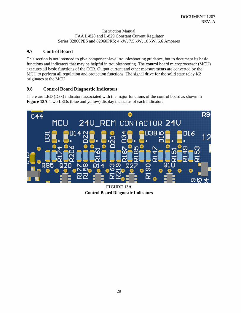
9.7 Control Board This section is not intended to give component-level troubleshooting guidance, but to document its basic functions and indicators that may be helpful in troubleshooting. The control board microprocessor (MCU) executes all basic functions of the CCR. Output current and other measurements are converted by the MCU to perform all regulation and protection functions. The signal drive for the solid state relay K2 originates at the MCU.
9.8 Control Board Diagnostic Indicators There are LED (Dxx) indicators associated with the major functions of the control board as shown in Figure 13A. Two LEDs (blue and yellow) display the status of each indicator.
FIGURE 13A
Control Board Diagnostic Indicators

DOCUMENT 1207 REV. A
Instruction Manual FAA L-828 and L-829 Constant Current Regulator
Series 82860PES and 82960PRS; 4 kW, 7.5 kW, 10 kW, 6.6 Amperes
30
FIGURE 13B
Control Board Complete

DOCUMENT 1207 REV. A
Instruction Manual FAA L-828 and L-829 Constant Current Regulator
Series 82860PES and 82960PRS; 4 kW, 7.5 kW, 10 kW, 6.6 Amperes
31
9.9 MCU (Microprocessor Control Unit) Indicator “D31” This indicates the status of the MCU. While the MCU is executing software normally, the blue LED D31 for this indicator will be illuminated. The yellow LED indicator D14 will be illuminated if the MCU is halted, or has encountered an internal error.
9.10 24V Remote Indicator “D22” & “D20” This indicates the operating range of the 24VDC internal remote voltage. While the internal remote power supply is operating within its normal range, the blue LED D22 for this indicator will be illuminated. The yellow LED indicator D20 will be illuminated if power supply is out of range or switched off (dip switch must be configured per section 7.19-7.20 and the jumper moved on Control Board 34229 from E2/E3 to E1/E2 ).
9.11 Contactor Indicator “D34” & “D38” A blue LED D34 in this position indicates that the main contactor K1 is being signaled to turn on. If the contactor is signaled off, the yellow LED D38 will be illuminated.
9.12 24V Indicator “D15” & “D16” This indicates the operating range of the main 24VDC input supply to the control board. While this voltage is in the correct range, the blue LED D15 will be illuminated, the yellow LED D16 will be illuminated otherwise.
9.13 Control Board Relay Indicators “D11” to “D18” There are LED indicators associated with each of the 8 control board relays as shown in Figure 14. Each blue LED is illuminated when its associated relay is energized and the normally open contact is closed.

DOCUMENT 1207 REV. A
Instruction Manual FAA L-828 and L-829 Constant Current Regulator
Series 82860PES and 82960PRS; 4 kW, 7.5 kW, 10 kW, 6.6 Amperes
32
FIGURE 14
Control Board Relay Indicators
9.14 Output Current Regulation Output current is provided through the output terminal from the main transformer T1. When the CCR is commanded to a step by local or remote control, the main contactor K1 is closed and connects mains power to T1. The RMS output current value is sensed by current transformer T3 and converted to a digital value. The value is then compared to a digital set point internal to the MCU on the Control Board. The controller regulates the current by providing a switched Pulse Width Modulated (PWM) signal to solid state relay K2. When K2 is switched fully on (shorted), the minimum amount of power will be provided by T1. When K2 is switched fully off (open), T1 provides the maximum amount of power. The switching of K2 must be synchronized to a signal provided by a specific sync winding (R1 and R2 connections) on T1. The output current waveform is shaped and regulated in part by the capacitor bank attached to the CAP windings on T1.

DOCUMENT 1207 REV. A
Instruction Manual FAA L-828 and L-829 Constant Current Regulator
Series 82860PES and 82960PRS; 4 kW, 7.5 kW, 10 kW, 6.6 Amperes
33
FIGURE 15
Regulation Troubleshooting Flowchart

DOCUMENT 1207 REV. A
Instruction Manual FAA L-828 and L-829 Constant Current Regulator
Series 82860PES and 82960PRS; 4 kW, 7.5 kW, 10 kW, 6.6 Amperes
34
9.15 Remote Control The remote control consists of a series of optically isolated digital input lines and an internally regulated 24VDC power supply on the control board. The remote signals are rectified and filtered for compatibility with externally supplied 120VAC remote systems. Jumper connections E1-E3, see sections 7.16- 7.18 select internal or external power. Both of the control board internal remote power and external neutral connection are fused, F1 and F2 (1/8A, SLO-BLO, 5 x 20mm, BUSSMAN GMD-125MAor equal). Voltage applied to a remote input connection activates that input. Open connections are deactivated. Both CC and B1 connections must have voltage applied to operate other remote steps. The local control switch must me set to “REMOTE” for the CCR to respond to remote signals.

DOCUMENT 1207 REV. A
Instruction Manual FAA L-828 and L-829 Constant Current Regulator
Series 82860PES and 82960PRS; 4 kW, 7.5 kW, 10 kW, 6.6 Amperes
35
FIGURE 16 Remote Control Troubleshooting Flowchart
Note, to read values with cabinet door closed and cover on, wires need to be connected to terminal block positions that will be checked and then routed to the outside of the cabinet interior.

DOCUMENT 1207 REV. A
Instruction Manual FAA L-828 and L-829 Constant Current Regulator
Series 82860PES and 82960PRS; 4 kW, 7.5 kW, 10 kW, 6.6 Amperes
36
FIGURE 17
Standard Wiring Diagram, Complete (see Figures 17A & B for enlarged halves of this diagram)

DOCUMENT 1207 REV. A
Instruction Manual FAA L-828 and L-829 Constant Current Regulator
Series 82860PES and 82960PRS; 4 kW, 7.5 kW, 10 kW, 6.6 Amperes
37
FIGURE 17A
Standard Wiring Diagram, Part A

DOCUMENT 1207 REV. A
Instruction Manual FAA L-828 and L-829 Constant Current Regulator
Series 82860PES and 82960PRS; 4 kW, 7.5 kW, 10 kW, 6.6 Amperes
38
FIGURE 17B Standard Wiring Diagram, Part B
DOCUMENT 1207 REV. A
Instruction Manual FAA L-828 and L-829 Constant Current Regulator
Series 82860PES and 82960PRS; 4 kW, 7.5 kW, 10 kW, 6.6 Amperes
39
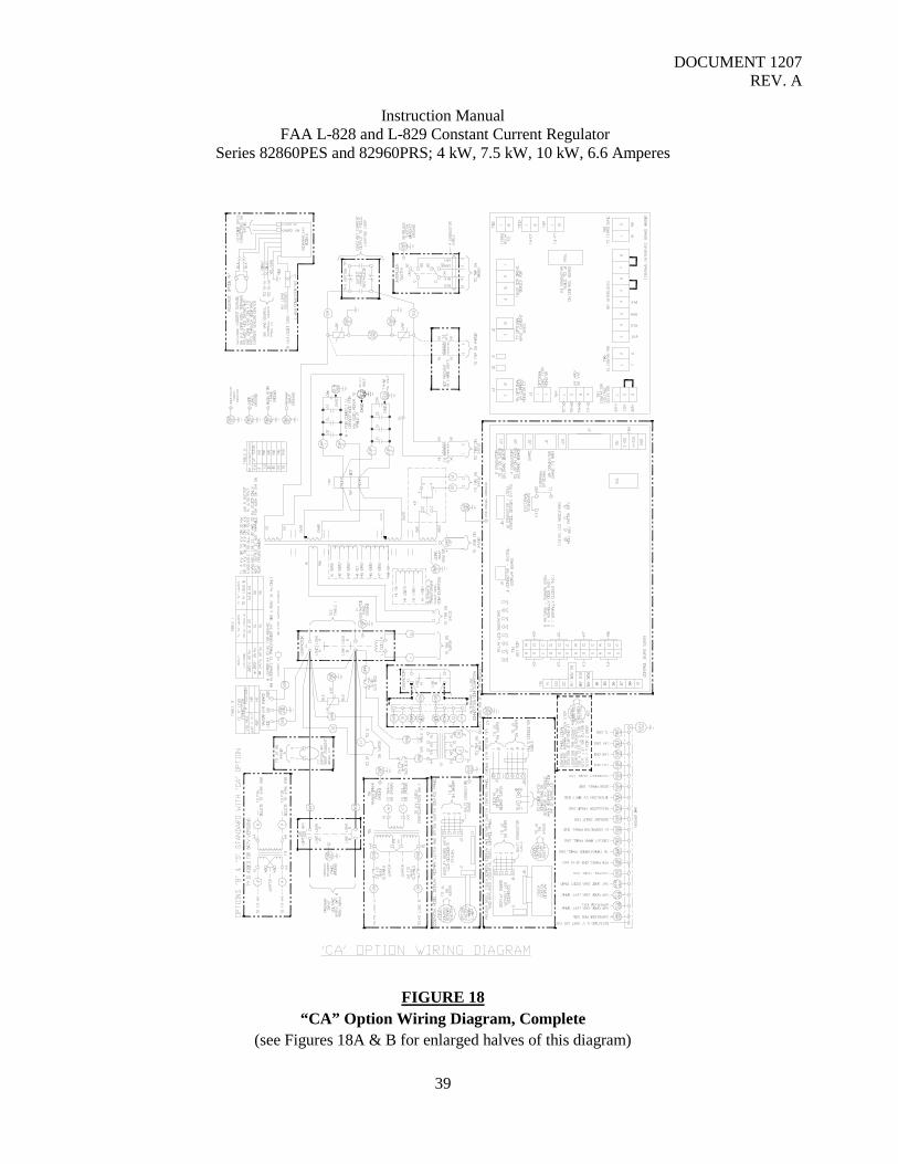
FIGURE 18 “CA” Option Wiring Diagram, Complete
(see Figures 18A & B for enlarged halves of this diagram)

DOCUMENT 1207 REV. A
Instruction Manual FAA L-828 and L-829 Constant Current Regulator
Series 82860PES and 82960PRS; 4 kW, 7.5 kW, 10 kW, 6.6 Amperes
40
FIGURE 18A “CA” Option Wiring Diagram, Part A

DOCUMENT 1207 REV. A
Instruction Manual FAA L-828 and L-829 Constant Current Regulator
Series 82860PES and 82960PRS; 4 kW, 7.5 kW, 10 kW, 6.6 Amperes
41
FIGURE 18B “CA” Option Wiring Diagram, Part B

DOCUMENT 1207 REV. A
Instruction Manual FAA L-828 and L-829 Constant Current Regulator
Series 82860PES and 82960PRS; 4 kW, 7.5 kW, 10 kW, 6.6 Amperes
42
9.16 Recommended Torque Values for CCR Hardware
REGULATOR TORQUE VALUES - SCREWS & BOLTS THREAD
SIZE MATERIAL TORQUE VALUE
*1/4 Type F STL, Zinc Plated 40 - 50 in-lb *1/4-28 STL, Zinc Plated 40 - 50 in-lb 1/2-13 STL (T1 Mtg Bolts) 500 - 550 in-lb
*1/4-28 BRASS 20 - 30 in-lb 1/4-20 BRASS 20 - 30 in-lb
5/16-18 BRASS 45 - 60 in-lb 3/8-16 BRASS 50 - 75 in-lb #6-32 STN STL 5 - 6 in-lb #8-32 STN STL 10 - 15 in-lb
#10-32 STN STL 18 - 20 in-lb 3/8-16 STN STL 130 - 150 in-lb
K1 & CB1 See Markings on Part
K2 Small Screw = 10 in-lb Large Screw = 18 in-lb
* = Present on Option "CA" only TABLE 3
CCR Screw and Bolt Recommended Torque Values (unless otherwise specified)

DOCUMENT 1207 REV. A
Instruction Manual FAA L-828 and L-829 Constant Current Regulator
Series 82860PES and 82960PRS; 4 kW, 7.5 kW, 10 kW, 6.6 Amperes
43
TABLE 4 CCR Hex Nut Recommended Torque Values (unless otherwise specified)
9.17 Recommended CCR Spare Parts The number of recommended parts depends on the quantity of PRO POWER Series CCRs present at your airfield. These spare parts will help in operational restoration of your CCRs if problems arise. Some parts may have higher spare part on hand recommendations, based on getting the CCRs basic functions restored if problems arise. For 1 to 10 CCRs:
Solid State Relay(SSR) (K2), P/N 10047-2789, quantity 1* Thermal Pad for Solid State Relay K2, P/N 10047-2937, quantity 1* * = Purchase Kit, P/N 34207 which contains quantity 1 each of P/N 10047-2789 and 10047-2937. Thermal Pad must be changed when replacing K2 SSR. Main Circuit Card, P/N 34229, quantity 1 Main Circuit Card Fuses F1 and F2, P/N 10047-2889, quantity 4 Interface Circuit Card, P/N 34232, quantity 1 Interface Circuit Card Fuses F1 and F2, P/N 10047-2890, quantity 4 Rotary Step Switch/Cable Assembly, P/N 34311, quantity 1 Rotary Switch Step Knob (requires .050 hex key to tighten), P/N 10041-31, quantity 1 F1 Fuses (Option “CA”), Bussman 3/4A FNQ-R, quantity 2 (4 if 30 kW, 240V)(C-H Airport Lighting P/N 10047-2933) Capacitor (C1), P/N 32990, quantity 4
REGULATOR TORQUE VALUES - HEX NUTS THREAD
SIZE MATERIAL TORQUE VALUE
*1/4-28 BRASS 20 - 30 in-lb 1/4-20 BRASS 20 - 30 in-lb 3/8-16 BRASS 50 - 75 in-lb #8-32 STN STL 10 - 15 in-lb
#10-32 STN STL
W/NYLON 20 - 25 in-lb
1/4-20 STN STL
W/NYLON 80 - 90 in-lb
3/8-16 STN STL
W/NYLON 260 - 300 in-lb 1/2-13 STN STL 500 - 550 in-lb
1/2-13 STN STL
W/NYLON 500 - 550 in-lb * = Present on Option "CA" only

DOCUMENT 1207 REV. A
Instruction Manual FAA L-828 and L-829 Constant Current Regulator
Series 82860PES and 82960PRS; 4 kW, 7.5 kW, 10 kW, 6.6 Amperes
44
Additional recommended spare parts for 1 to 50 CCRs: Display Circuit Card (Essential Model), P/N 34313-1, quantity 1 Display Circuit Card (Premium Model), P/N 34313-2, quantity 1 Touch Pad and its Integral Circuit Card (Premium Model), P/N 10047-3176, quantity 1 Option Switch/Cable Assembly (Essential Model), P/N 34250, quantity 1 Option Switch Knob (Essential Model, requires 1/8 wide blade screwdriver to tighten), P/N 10041-40, quantity 1 Main Circuit Card to Interface Circuit Card Cable Assembly, P/N 34248, quantity 1 J2 Cable Assembly, P/N 34315, quantity 1 Digitrac Interface Circuit Card (Option “D” & “M”), P/N 34235, quantity 1 Digitrac J1 to 34229 J11 Cable Assembly (Option “D” & “M”), P/N 34309, quantity 1 Digitrac J10 to 34229 J5 Cable Assembly (Option “D” & “M”), P/N 34310, quantity 1 Contactor (K1), P/N 10047-1249, quantity 1
9.18 Major CCR Parts and Locating Figures Figures 19 through 28 show major parts, their part numbers and location in the CCR that can be purchased from Crouse-Hinds. The user should retain any mounting and leads for re-use on the replacement part. Please note that some components shown are only present if the particular option was factory installed at initial order.

DOCUMENT 1207 REV. A
Instruction Manual FAA L-828 and L-829 Constant Current Regulator
Series 82860PES and 82960PRS; 4 kW, 7.5 kW, 10 kW, 6.6 Amperes
45
FIGURE 19
Major Replaceable Parts
LOCALCONTROLSWITCH
1
2
3
45
OFFREMOTE
OPTIONCONTROL SWITCH

DOCUMENT 1207 REV. A
Instruction Manual FAA L-828 and L-829 Constant Current Regulator
Series 82860PES and 82960PRS; 4 kW, 7.5 kW, 10 kW, 6.6 Amperes
46
FIGURE 20
Major Replaceable Parts
LOCALCONTROLSWITCH
1
2
3
45
OFFREMOTE
OPTIONCONTROL SWITCH

DOCUMENT 1207 REV. A
Instruction Manual FAA L-828 and L-829 Constant Current Regulator
Series 82860PES and 82960PRS; 4 kW, 7.5 kW, 10 kW, 6.6 Amperes
47
FIGURE 21
Major Replaceable Parts
CABGND
EXTGND

DOCUMENT 1207 REV. A
Instruction Manual FAA L-828 and L-829 Constant Current Regulator
Series 82860PES and 82960PRS; 4 kW, 7.5 kW, 10 kW, 6.6 Amperes
48
FIGURE 22 Major Replaceable Parts
INTGND

DOCUMENT 1207 REV. A
Instruction Manual FAA L-828 and L-829 Constant Current Regulator
Series 82860PES and 82960PRS; 4 kW, 7.5 kW, 10 kW, 6.6 Amperes
49
FIGURE 23 Major Replaceable Parts
C1
CABGND
EXTGND
INPUTCB1
WARNINGDISCHARGE CAPACITORSBEFORE HANDLING
HIGHVOLTAGE
DANGER
BEFORE HANDLINGDISCHARGE CAPACITORS
WARNING

DOCUMENT 1207 REV. A
Instruction Manual FAA L-828 and L-829 Constant Current Regulator
Series 82860PES and 82960PRS; 4 kW, 7.5 kW, 10 kW, 6.6 Amperes
50
FIGURE 24 Major Replaceable Parts
CA
P2
CA
P1
TB3
C1
BEFORE HANDLINGDISCHARGE CAPACITORS
WARNING

DOCUMENT 1207 REV. A
Instruction Manual FAA L-828 and L-829 Constant Current Regulator
Series 82860PES and 82960PRS; 4 kW, 7.5 kW, 10 kW, 6.6 Amperes
51
FIGURE 25
Major Replaceable Parts
T1LA3
LA2
LA2 OUTPUT
K2
LA1
T3
E1
T4
TB2
T7 K1
INPUT
INPUTGND
T2
T9
LA3 OUTPUT

DOCUMENT 1207 REV. A
Instruction Manual FAA L-828 and L-829 Constant Current Regulator
Series 82860PES and 82960PRS; 4 kW, 7.5 kW, 10 kW, 6.6 Amperes
52
FIGURE 26
Major Replaceable Parts
T1LA3
LA2
LA2 OUTPUT
K2
T3
E1
T4
TB2
T7 K1
INPUT
INPUTGND
T2
T9
LA3 OUTPUT

DOCUMENT 1207 REV. A
Instruction Manual FAA L-828 and L-829 Constant Current Regulator
Series 82860PES and 82960PRS; 4 kW, 7.5 kW, 10 kW, 6.6 Amperes
53
FIGURE 27
Major Replaceable Parts
DOORGND
12
BLOCKTERMINALCONTROLREMOTE
B2/B30
B4
B610
B5
11
B3/B100
TB1
CC
N
B1/B10/0N
CCI

DOCUMENT 1207 REV. A
Instruction Manual FAA L-828 and L-829 Constant Current Regulator
Series 82860PES and 82960PRS; 4 kW, 7.5 kW, 10 kW, 6.6 Amperes
54
FIGURE 28
Major Replaceable Parts
LOCALCONTROLSWITCH
1
2
3
45
OFFREMOTE

DOCUMENT 1207 REV. A
Instruction Manual FAA L-828 and L-829 Constant Current Regulator
Series 82860PES and 82960PRS; 4 kW, 7.5 kW, 10 kW, 6.6 Amperes
55
10 L-829 Monitor and Option “P”; Use and Display, Pro Power Essential Models L-829 monitoring provides sensing and alarms for the following FAA specified internal and external faults:
1) Loss of input power to the CCR. 2) Shutdown of the CCR due to operation of protective circuits. 3) A 10 percent or greater drop in the volt-amperes (VA) delivered to the series circuit. 4) Failure of the regulator to deliver the output current that corresponds to the brightness step
selected. 5) Failure of a preset number of lamps in the field circuit.
Items 1, 2 and 4 are standard and active in both L-828 and L-829 CCRs. Lamp out detection and circuit power detection are the two remaining monitor functions described below. Each of these modes can be activated or deactivated. All setup and calibration for Pro Power Essential L-829 is accomplished using the option control knob on the CCR front panel (see section 8.3). L-829 data entry and mode selection can be visualized as a menu navigated using the option control knob. Figure 29 shows the L-829 menu tree.
WARNING:
IMPORTANT
L-829 Monitoring will not work for LED fixtures. This is true regardless of LED fixtures being from the same manufacturer, and even being the same type. LED fixtures may have unique shorting present in their power supply or board circuitry to meet FAA EB67 requirements, or in other specifications which allow fixtures with multiple LEDs in the fixture to have some of them not functioning as long as a certain percentage are working as required by their particular requirements.

DOCUMENT 1207 REV. A
Instruction Manual FAA L-828 and L-829 Constant Current Regulator
Series 82860PES and 82960PRS; 4 kW, 7.5 kW, 10 kW, 6.6 Amperes
56
FIGURE 29 L-829 Menu Tree
10.1 Pro Power Essential L-829 Setup and Calibration
WARNING:
IMPORTANT Before entering setup data for L-829 functions, disable both detection modes. This will prevent false alarm indications during setup.
Push and hold the option control knob for approximately 3 seconds until “L829” appears on the display, and release. Push the knob again to enter the L-829 menu. Rotate the knob to navigate between “CNT”

DOCUMENT 1207 REV. A
Instruction Manual FAA L-828 and L-829 Constant Current Regulator
Series 82860PES and 82960PRS; 4 kW, 7.5 kW, 10 kW, 6.6 Amperes
57
(count), and “PCT” (percent), and “dd” (degraded). These menu items represent the three L-829 detection modes available. In order to indicate that each mode is active, a small circle will be displayed to the left of setting as shown in Figure 30 below.
FIGURE 30 Indication of Active Percent Mode
Verify that both “CNT”, “PCT” and “dd” modes are inactive. If a mode is active, rotate the option control knob until it shows the active setting, then push and hold the knob for approximately 3 seconds. The display will flash to acknowledge the command and the active indicator should no longer appear. The L-829 detection modes are now disabled. Rotate the knob until “done” is displayed. Push the knob to exit the menu.
10.2 Percent Power Monitor The percent power monitor detects problems in the field circuit by detecting changes in the power profile of the circuit. This detection mode may be used on any circuit including circuits with mixed types of devices. The only initial data to be saved is the power profile (W and VA) of the circuit when it is fully connected and in good condition. This monitor mode will detect changes from this initial condition specifically a 10% rise or fall in power (W) or a 10% rise or fall in apparent power (VA).
10.3 Circuit Power Calibration
WARNING:
IMPORTANT The field circuit must be fully connected and in good operating condition before attempting calibration.
Use the local control knob to operate the CCR at the maximum brightness setting. Operate the field circuit for a minimum of 20 minutes to allow temperature of wiring and fixtures to stabilize. The circuit power profile may change significantly due to heating. Refer to Figure 29 while navigating through the L-829 menu tree. Press and hold the option control knob for approximately 3 seconds until “L829” appears on the display, and release. Rotate the knob until “PCAL” (power calibration) appears on the display.

DOCUMENT 1207 REV. A
Instruction Manual FAA L-828 and L-829 Constant Current Regulator
Series 82860PES and 82960PRS; 4 kW, 7.5 kW, 10 kW, 6.6 Amperes
58
Press and hold the option knob to activate power calibration. “PCAL” will flash on the display during calibration. The CCR will automatically detect and save the field circuit power profile at the two maximum brightness steps. The calibration routine will last approximately 1 minute. When the routine has completed successfully, only maximum brightness step current will be displayed.
10.4 Lamp Out Monitor The lamp out monitor will provide alarm indications when a user specified number of lamps have failed. This type of monitoring is only accurate given the following:
1) All lamps on the circuit must be of the same type and wattage. 2) All isolation transformers must be the same wattage and manufacturer. 3) Lamps must be incandescent types. LED fixtures cannot be monitored accurately in lamp count
mode. 4) No film disc cut-outs may be used
The lamp out alarm has two alarm levels. The initial alarm is triggered when a user specified number of lamps have failed. The initial alarm may be cleared and the CCR will operate in a degraded mode. In this mode, the CCR will alarm again only after an additional user specified number of lamps has failed. There are 4 data items that must be entered in lamp count mode:
1) The power profile of the field circuit when it is fully operational with no lamp failures. 2) The number of lamp failures that will trigger the initial alarm (4-10). 3) The number of additional lamp failures that will trigger a second alarm after the first alarm is
cleared (1-5). 4) The power profile of the field circuit with the exact number of lamps removed (open transformer)
as were chosen in step 2.
10.5 Lamp out settings and Calibration Refer to Figure 29 while navigating through the L-829 menu tree.
10.6 Power Calibration Power calibration must be performed first as part of the lamp out calibration routine. Refer to section 10.3.
10.7 First Lamp threshold When power calibration has been completed, enter first lamp threshold. This is the number of lamps (4-10) that will trigger the initial lamp alarm. Press and hold the option control knob for approximately 3 seconds until “L829” appears on the display, and release. Push the knob again to enter the L-829 menu. Rotate the knob until “LPTH” (lamp threshold) appears on the display. Push the knob again and a number will appear on the display. This number is the current lamp threshold setting.

DOCUMENT 1207 REV. A
Instruction Manual FAA L-828 and L-829 Constant Current Regulator
Series 82860PES and 82960PRS; 4 kW, 7.5 kW, 10 kW, 6.6 Amperes
59
Rotate the knob to select the required number of lamp failures that will trigger the first alarm. Press and hold the option knob to save the lamp threshold. The display will flash to confirm that the data has been saved and then return to the menu item “LPTH”.
10.8 Second Lamp Threshold The first alarm threshold is cleared by entering degraded mode. The second lamp threshold will set the number of lamp failures that will trigger an alarm in degraded mode. The display should still be operating in the L-829 menu. Rotate the option control knob until “LPdd” (lamp degraded) appears on the display. Push the knob again and a number will appear on the display. This number is the current degraded lamp threshold setting. Rotate the knob to select the required number of lamp failures (1-5) that will trigger the degraded mode alarm. Press and hold the option knob to save the lamp threshold. The display will flash to confirm that the data has been saved and then return to the menu item “LPdd”.
10.9 Lamp out Calibration In order to accurately determine the number of lamps that have failed, the CCR must perform a calibration with the exact number of lamps removed matching the first alarm threshold entered in section 10.7.
WARNING:
IMPORTANT
See DANGER warning below. Unplug the correct number of lamps from their isolation transformer secondary connection in the airfield series lighting circuit after CCR power lock out is performed. Do not install shorting plugs. Restore CCR power after lamp have been unplugged. Perform calibration, and lock out CCR after calibration to re-install lamps to series circuit. Restore CCR power.
DANGER:
DANGER
Lock Out electrical power to the Constant Current Regulator (CCR) at its source before lamp out calibration per this section is performed or if opening the CCR door and attempting servicing. Note, if the CCR is equipped with an integral circuit breaker (Option “B”), power is present at CB1 input terminals even with the circuit breaker in the “off” position. Lock Out electrical power prior to CB1 if entering the CCR cabinet.

DOCUMENT 1207 REV. A
Instruction Manual FAA L-828 and L-829 Constant Current Regulator
Series 82860PES and 82960PRS; 4 kW, 7.5 kW, 10 kW, 6.6 Amperes
60
Use the local control knob to operate the CCR at the maximum brightness setting. Operate the field circuit for a minimum of 20 minutes to allow temperature of wiring and fixtures to stabilize. The circuit power profile may change significantly due to heating, affecting calibration results. The display should still be operating in the L-829 menu. Rotate the option control knob until “LCAL” (lamp calibration) appears on the display. Press and hold the option knob to activate lamp calibration. “LCAL” will flash on the display during calibration. The CCR will automatically detect and save the field circuit lamp out power profile at the two maximum brightness steps. The calibration routine will last approximately 1 minute. When the routine has completed successfully, only maximum brightness step current will be displayed and normal operation has resumed.
10.10 L-829 Relay Indicators Remote indication of L-829 alarms is accomplished through isolated relay contacts available on the control board TB3.
10.11 L-829 Operation Once L-829 data has been entered and calibration is complete, the desired detection mode may be activated.
WARNING:
IMPORTANT Although both modes may be activated, lamp-out monitoring will be incorrect on circuits with mixed fixture or transformer wattages, and should be deactivated on these types of circuits.
Refer to section 10.1 for L-829 mode activation and deactivation. In power percentage mode no user intervention is required.
10.12 Lamp-out Operation When the CCR is operating normally and the user specified number of lamps has failed (first alarm), “LOUT” will appear on the display (Table 5) and the lamp-out relay will energize. Replacement of failed lamps should be completed at this time. If repair cannot be completed, then enter degraded mode as described in Section 10.1. When the CCR is operating in degraded mode, the display will alternately flash “on”, “dd” along with the brightness step current. After the additional number of user selected lamps has failed, “LOUT” will appear on the display. Replacement of failed lamps must be completed at this time to prevent the lamp-out alarm from appearing.
10.13 L-829 Alarms When a specified alarm limit has been reached, the display will indicate the alarm as shown in Table 5 below. If multiple alarms are active, the display will cycle through each alarm.

DOCUMENT 1207 REV. A
Instruction Manual FAA L-828 and L-829 Constant Current Regulator
Series 82860PES and 82960PRS; 4 kW, 7.5 kW, 10 kW, 6.6 Amperes
61
Table 5
L-829 Alarm Displays
10.14 Option “P” (Input Line Voltage and Input Line Current) Display To display Input Line Voltage, TBD. To Display Input Line Current, TBD.
L-829 DISPLAY DESCRIPTION
Lamps Out: Appears when the selected number of lamps has failed in either normal or degraded mode.
Step: The CCR is unable to reach the specified output current required by selected brightness step.
Power High: The circuit real power (W) has risen by 10% or more since original calibration.
Power Low: The circuit real power (W) has fallen by 10% or more since original calibration.
Apparent Power High: The circuit apparent power (VA) has risen by 10% or more since original calibration.
Apparent Power Low: The circuit apparent power (VA) has fallen by 10% or more since original calibration.

DOCUMENT 1207 REV. A
Instruction Manual FAA L-828 and L-829 Constant Current Regulator
Series 82860PES and 82960PRS; 4 kW, 7.5 kW, 10 kW, 6.6 Amperes
62
11 L-829 Monitor, Digitrac, Megatrac and Option “P”; Use and Display , Pro Power Premium Models (Touch Screen)
Under development. TBD.


![KW-R925BTS / KW-R920BTS · Data Size: B6L (182 mm x 128 mm) Book Size: B6L (182 mm x 128 mm) ENGLISH FRANÇAIS ESPAÑOL B5A-0831-00 [K] KW-R925BTS / KW-R920BTS CD RECEIVER INSTRUCTION](https://static.fdocuments.in/doc/165x107/6042d8b7daa11d3c657e2b35/kw-r925bts-kw-r920bts-data-size-b6l-182-mm-x-128-mm-book-size-b6l-182-mm.jpg)