Instruction Manual - CompX International...
20
StealthLock ® , Keyless Invisible Security 1 Instruction Manual
Transcript of Instruction Manual - CompX International...
StealthLock®
, Keyless Invisible Security 1
Instruction Manual

StealthLock®
, Keyless Invisible Security 2
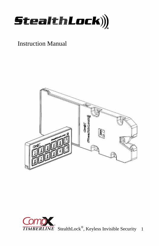
Thank you for purchasing StealthLock®. StealthLock® is an innovative solution for
keyless invisible security. Using radio frequency technology, StealthLock® allows you to
secure almost any wood cabinet door or drawer with little or no changes to the cabinet
design.
StealthLock® is battery operated and works with a user established 4 to 8 digit code.
Operation is simple: input your code and press lock or unlock. The Latch can operate any
Receiver Latch within a 15 foot range which allows it to be placed anywhere, leaving no
trace of visible hardware. In addition, the Latch can operate multiple Receiver Latches to
secure an entire room or bank of cabinets.
StealthLock® is designed to install and program easily and offers:
Programmable user and supervisor codes
Programmable modes of operation
Programmable reset features
StealthLock® is recommended for use on cabinets made from:
Wood
Wood products
Phenolic resin
Glass
StealthLock® is NOT intended for:
Metal furnishings or cabinets
Exterior furnishings or cabinets
Applications where temperatures fall below 50° F or above 120° F
StealthLock® may be used in households to help protect minors from unsafe materials.
It is strongly recommended that all batteries used by the StealthLock® be replaced on an
annual basis. Please mark this date on your calendars to insure replacement. In the event
you have allowed the batteries to die, you will need to forcefully enter the cabinet. The
StealthLock® strike plate is designed to shear away at 80lbs of force. A new strike plate
will then be needed to operate the lock.

StealthLock®
, Keyless Invisible Security 3
1 – TL-600
Installation Tool
1 – TP-100
Transmitter Pad
CR2032 Battery Included
1 – SP-600
Cabinet Strike Plate
Screws Included
1 – RL-100
Receiver Latch
Screws Included
SL-100 StealthLock® Contents
2.500
.437
6.785
3.375
.325
1.500
1.250
2.670
ACR0SS
REAR TABS
.350

StealthLock®
, Keyless Invisible Security 4
Battery Installation – Receiver Latch
While gripping the rear
tabs, slide the battery
housing in and up as
shown
Slide the battery
housing back until it is
completely free of the
Receiver Latch
Install four AAA batteries in
the slots indicated on the back
of the battery housing.
The Receiver Latch uses 4 AAA batteries that
are expected to last 2 years in normal operation
(4 open/close cycles per day).
Batteries should be replaced on an annual basis
to insure continued reliability.
The LED will begin to blink after 5,500 operations
to warn that batteries need to be replaced

StealthLock®
, Keyless Invisible Security 5
Battery Installation - Transmitter Pad
During initial installation, remove
the red ribbon to activate the
installed battery
To replace the battery, insert a
small flat blade screwdriver into
the battery tray slot as shown
Rotate the Screwdrive up
(clockwise) as shown to release
the battery tray.
Replace old battery with fresh CR2032
making sure that the positive (+) side of the
battery is facing down in the battery tray
Slide the battery tray back into the transmitter
housing and snap into place
The Transmitter Pad uses a CR2032 battery
that is expected to last 2 years in normal
operation (4 open/close cycles per day).
Batteries should be replaced on an annual basis
to insure continued reliability.
The LED will begin to blink after
5,500 operations to warn that
batteries need to be replaced

StealthLock®
, Keyless Invisible Security 6
Installation Instructions – Receiver Latch
The StealthLock® is designed to operate within non-metallic cabinetry. Use with other
materials may limit or prohibit operation of the lock. We recommend testing the lock if
using in a material other than wood. Batteries should be installed before installation.
The SL-100 StealthLock® kit is designed for
mounting in cabinets with solid panel
construction and full overlay doors. An
INSTALLATION VIDEO and tips for
mounting this kit in other cabinet types can
be found at www.stealthlock.com
Step #1 - Position the Receiver Latch with
strike plate and installation tool attached as
shown. The front tabs on the installation tool
should contact the front edge
of the cabinet
Installation Tool Tabs
Front Edge of Cabinet
Step #2 - Screw the Receiver Latch in place using
2 of the #6 x ½” screws supplied, in the front side
of the oval holes. If attaching to material less than
¾” thick, alternate fasteners may be required.
Start with Screws in Front
Side of Oval Holes

StealthLock®
, Keyless Invisible Security 7
Step #3 – Press the learn button
on the Receiver Latch until the
yellow LED lights to insure that
the Latch is in the open position
Step #4 – Remove release paper
from the back of the strike plate
Learn
Button
Step #5 – Close door firmly and open it
again. The strike plate will become
affixed to the door in the proper
mounting position. Remove and discard
red installation tool
Step #6 - Screw the strike plate in
place using 2 of the #6 x ½” screws
supplied. If attaching to material
less than ¾” thick, alternate
fasteners may be required.
Step #7 – Check the fit after any bumpers are installed. Door should
latch into the Receiver Latch and still have a little free play. Adjust
Receiver Latch forward on oval holes as required.
Release Paper
Finish by installing the remaining
screws at the front of the Receiver Latch

StealthLock®
, Keyless Invisible Security 8
Installation Instructions – Transmitter Pad
The Transmitter Pad has a functional range of 15 feet from the Receiver Latch and can be
mounted virtually anywhere on any non-metallic panel. To mount, simply remove the
release paper from the tape on the back side of the Transmitter Pad, and press into place.
Suggested mounting areas
Cabinet door face or drawer face
Wall above switch plate
Inside unlocked cabinet door or drawer to be hidden
Remove release
paper from tape

StealthLock®
, Keyless Invisible Security 9
Programming – Introduction
StealthLock® is very easy to use and operate. Once installed, the user enters the user
code (factory default 0000) and presses Lock to lock the cabinet. To unlock the
cabinet, the user enters the user code and presses Unlock and the cabinet will open.
StealthLock® is fully programmable allowing the user or supervisor the ability to change
codes, modes, and restore lock settings. While the StealthLock® is easy to program, we
highly recommend reading the complete programming instructions prior to making any
changes. Remember to keep track of any changes made in a secure location.
Key locations and indicator lights referenced in the programming instructions are shown
below.
RL-100 Receiver Latch
Yellow and Green
LED Indicator
Learn Button – Use pen tip or
paper clip to depress

StealthLock®
, Keyless Invisible Security 10
Programming – Introduction
TP-100 Transmitter Pad
Please note the following:
StealthLock® will reset to an unlocked position whenever the learn button is
pressed.
Only one Transmitter Pad should be used for programming in a given area at
any one time. The StealthLock® is a radio frequency device and the use of
multiple Transmitter Pads in the same area may result in interference and
improper programming.
After pressing Lock or Unlock, the Green LED on the Transmitter Pad will
light for about 2 seconds indicating that a transmission is in progress.
While the Green LED on the Transmitter Pad is lit, the keypad will not respond
to any other entries until the transmission is completed.
If the Green LED on the Transmitter Pad flashes rapidly after pressing Lock or
Unlock, this indicates that an improper code has been entered. Codes must
always be 4 to 8 digits in length.
If the LED indicator on the Receiver Latch flashes Green/Yellow, this indicates
that an improper code as been received. Start the learning function over taking
care to enter the correct codes.
Unlock Button
Green LED
Indicator
Lock Button

StealthLock®
, Keyless Invisible Security 11
Programming the User Code
Use these steps to change your current user code. The factory default code is 0000. User
codes must be 4 to 8 digits in length. To view a video of these steps, go to
www.StealthLock.com Note that the user code can not be changed if the Receiver Latch
has been set to Single Use Mode.
There is a 60 second programming time limit to each step. If you time out or make an
error, programming will end and you will need to restart from step 1.
1. We suggest reading through the instructions prior to beginning programming
2. Press and hold the Receiver Latch learn button until the yellow LED light
begins a one blink pattern, then release
3. Using the Transmitter Pad enter the current user code and press the
Unlock button
4. Wait for green light on Transmitter Pad to turn off then enter the new user
code and press the Lock button
5. Wait for green light on Transmitter Pad to turn off then re-enter the new user
code and press the Lock button to secure code
6. If successful, the green LED light on the Receiver Latch will stay illuminated
for 3 seconds
7. Once the green LED light has turned off, the Receiver Latch will automatically
exit the learn mode
8. Test lock function with new code
9. We recommend writing down your new code in the back of these instructions
and storing in a safe area
StealthLock®
, Keyless Invisible Security 12
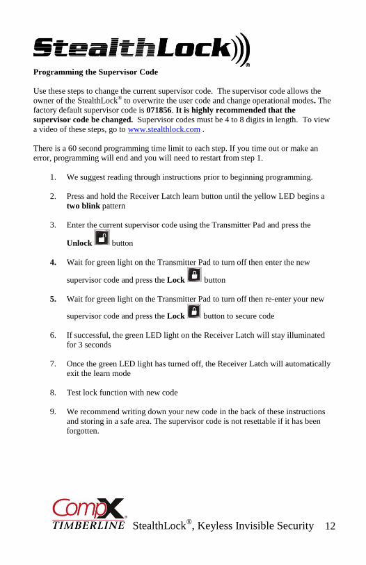
Programming the Supervisor Code
Use these steps to change the current supervisor code. The supervisor code allows the
owner of the StealthLock® to overwrite the user code and change operational modes. The
factory default supervisor code is 071856. It is highly recommended that the
supervisor code be changed. Supervisor codes must be 4 to 8 digits in length. To view
a video of these steps, go to www.stealthlock.com .
There is a 60 second programming time limit to each step. If you time out or make an
error, programming will end and you will need to restart from step 1.
1. We suggest reading through instructions prior to beginning programming.
2. Press and hold the Receiver Latch learn button until the yellow LED begins a
two blink pattern
3. Enter the current supervisor code using the Transmitter Pad and press the
Unlock button
4. Wait for green light on the Transmitter Pad to turn off then enter the new
supervisor code and press the Lock button
5. Wait for green light on the Transmitter Pad to turn off then re-enter your new
supervisor code and press the Lock button to secure code
6. If successful, the green LED light on the Receiver Latch will stay illuminated
for 3 seconds
7. Once the green LED light has turned off, the Receiver Latch will automatically
exit the learn mode
8. Test lock function with new code
9. We recommend writing down your new code in the back of these instructions
and storing in a safe area. The supervisor code is not resettable if it has been
forgotten.
StealthLock®
, Keyless Invisible Security 13
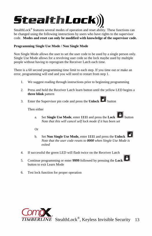
StealthLock® features several modes of operation and reset ability. These functions can
be changed using the following instructions by users who have rights to the supervisor
code. Modes and reset can only be modified with knowledge of the supervisor code.
Programming Single Use Mode / Non Single Mode
Non Single Mode allows the user to set the user code to be used by a single person only.
Single Use Mode allows for a revolving user code so the lock maybe used by multiple
people without having to reprogram the Receiver Latch each time.
There is a 60 second programming time limit to each step. If you time out or make an
error, programming will end and you will need to restart from step 1.
1. We suggest reading through instructions prior to beginning programming
2. Press and hold the Receiver Latch learn button until the yellow LED begins a
three blink pattern
3. Enter the Supervisor pin code and press the Unlock button
Then either
a. Set Single Use Mode, enter 1111 and press the Lock button
Note that this will cancel self lock mode if it has been set
Or
b. Set Non Single Use Mode, enter 1111 and press the Unlock
Note that the user code resets to 0000 when Single Use Mode is
exited
4. If successful the green LED will flash twice on the Receiver Latch
5. Continue programming or enter 9999 followed by pressing the Lock
button to exit Learn Mode
6. Test lock function for proper operation
StealthLock®
, Keyless Invisible Security 14
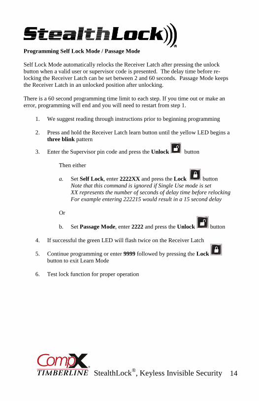
Programming Self Lock Mode / Passage Mode
Self Lock Mode automatically relocks the Receiver Latch after pressing the unlock
button when a valid user or supervisor code is presented. The delay time before re-
locking the Receiver Latch can be set between 2 and 60 seconds. Passage Mode keeps
the Receiver Latch in an unlocked position after unlocking.
There is a 60 second programming time limit to each step. If you time out or make an
error, programming will end and you will need to restart from step 1.
1. We suggest reading through instructions prior to beginning programming
2. Press and hold the Receiver Latch learn button until the yellow LED begins a
three blink pattern
3. Enter the Supervisor pin code and press the Unlock button
Then either
a. Set Self Lock, enter 2222XX and press the Lock button
Note that this command is ignored if Single Use mode is set
XX represents the number of seconds of delay time before relocking
For example entering 222215 would result in a 15 second delay
Or
b. Set Passage Mode, enter 2222 and press the Unlock button
4. If successful the green LED will flash twice on the Receiver Latch
5. Continue programming or enter 9999 followed by pressing the Lock
button to exit Learn Mode
6. Test lock function for proper operation

StealthLock®
, Keyless Invisible Security 15
Programming Learn Disable / Learn Enable
Learn Disable / Learn Enable Mode allows the supervisor to either allow or not allow a
user to program a new user code. In Learn Disable Mode, only the users with knowledge
of the supervisor code can make any programming changes.
There is a 60 second programming time limit to each step. If you time out or make an
error, programming will end and you will need to restart from step 1.
1. We suggest reading through instructions prior to beginning programming
2. Press and hold the Receiver Latch learn button until the yellow LED begins a
three blink pattern
3. Enter the Supervisor pin code and press the Unlock button
Then either
a. Set Learn Disable, enter 3333 and press the Lock button
Or
b. Set Learn Enable, enter 3333 and press the Unlock button
4. If successful the green LED will flash twice on the Receiver Latch
5. Continue programming or enter 9999 followed by pressing the Lock button to
exit Learn Mode
6. Test lock function for new mode operation. If Learn Disable has been set, the
Receiver Latch should automatically go to a three blink pattern when the learn
button is pushed and held.

StealthLock®
, Keyless Invisible Security 16
Reset Factory Default Settings
This feature returns the lock to its original factory settings. This will place the Receiver
Latch into a Non Single Use Mode, Passage Mode, and Learn Enable Mode. It does not
reset the user or supervisor code.
There is a 60 second programming time limit to each step. If you time out or make an
error, programming will end and you will need to restart from step 1.
1. We suggest reading through instructions prior to beginning programming
2. Press and hold the Receiver Latch learn button until the yellow LED begins a
three blink pattern
3. Enter the Supervisor pin code and press the Unlock button
4. Enter 4444 and press the Lock button
5. If successful the green LED will flash twice on the Receiver Latch.
Note that if Single Use mode was exited, the user pin code will default to 0000
6. Continue programming or enter 9999 followed by pressing the Lock
button to exit Learn Mode
7. Test lock function to make sure default settings are restored
StealthLock®
, Keyless Invisible Security 17
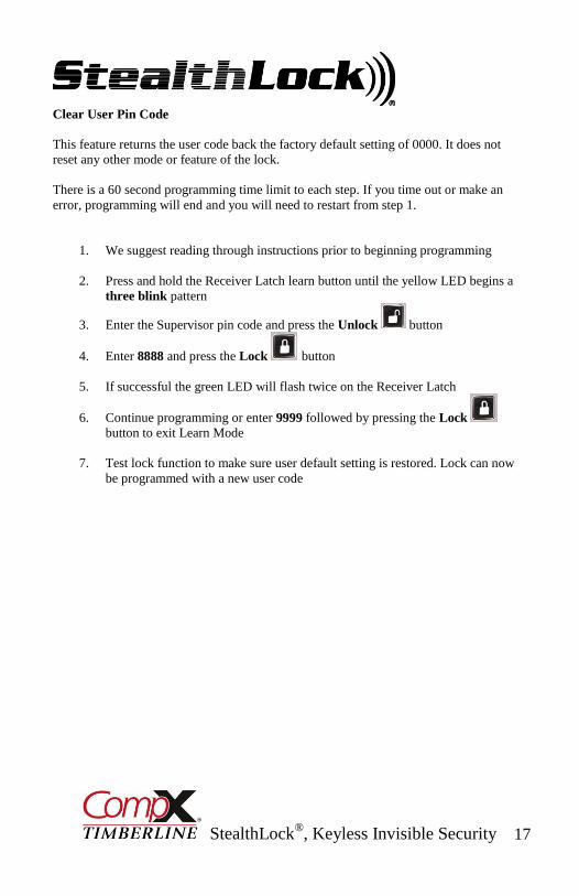
Clear User Pin Code
This feature returns the user code back the factory default setting of 0000. It does not
reset any other mode or feature of the lock.
There is a 60 second programming time limit to each step. If you time out or make an
error, programming will end and you will need to restart from step 1.
1. We suggest reading through instructions prior to beginning programming
2. Press and hold the Receiver Latch learn button until the yellow LED begins a
three blink pattern
3. Enter the Supervisor pin code and press the Unlock button
4. Enter 8888 and press the Lock button
5. If successful the green LED will flash twice on the Receiver Latch
6. Continue programming or enter 9999 followed by pressing the Lock
button to exit Learn Mode
7. Test lock function to make sure user default setting is restored. Lock can now
be programmed with a new user code

StealthLock®
, Keyless Invisible Security 18
Auxiliary Power
If desired, the StealthLock® Receiver Latch may
be connected to 120 VAC power using the
optional RL-AP1 Power Supply
Up to 10 Receiver Latches may
be powered from the same
Power Supply using the optional
RL-APC Power Cords as shown
RL-APC
Power Cords
RL-AP1
Power Supply
RL-AP1 Power Supply
(Includes 5-1/2 foot cord)
cord
RL-APC-3 Power Cord – 3 foot
RL-APC-5 Power Cord – 5 foot
RL-APC-10 Power Cord – 10 foot
Power
Port

StealthLock®
, Keyless Invisible Security 19
Transmitter Pad Mounting Accessories
MP-700-WM Mounting Plate
Satin Nickel Finish
Allows mounting to any
flat surface or wall
MP-700 Mounting Plate
Satin Nickel Finish
Allows mounting to material
5/8” – 7/8” Thick
Mounting screws and
template included
Wall mounting
screws not included
Mounting Plate
screws included

StealthLock®
, Keyless Invisible Security 20
Regulatory Information
The user is cautioned that changes or modifications not expressly approved by CompX
Timberline could void the user’s authority to operate the equipment.
This device complies with Part 15 of the FCC Rules. Operation is subject to the following
two conditions: (1) This device may not cause harmful interference, and (2) this device
must accept any interference received, including interference that may cause undesired
operation.
This equipment has been tested and found to comply with the limits for a Class B digital
device, pursuant to Part 15 of the FCC Rules. These limits are designed to provide
reasonable protection against harmful interference in a residential installation. This
equipment generates, uses and can radiate radio frequency energy and, if not installed and
used in accordance with the instructions, may cause harmful interference to radio
communications. However, there is no guarantee that interference will not occur in a
particular installation. If this equipment does cause harmful interference to radio or
television reception, which can be determined by turning the equipment off and on, the
user is encouraged to try to correct the interference by one or more of the following
measures:
Reorient or relocate the receiving antenna.
Increase the separation between the equipment and receiver.
Connect the equipment into an outlet on a circuit different from that to which
the receiver is connected.
Consult the dealer or an experienced radio/TV technician for help.
IS-600-K Copyright 2016 © CompX Security Products