Instruction Manual - CBS MAGVAC manual.pdf · flow across the vacuum bottle or interrupter assembly...
43
[i] 50 DH-MGV-250, 1200/2000A Medium-Voltage Vacuum Circuit Breaker Retrofit Instruction Manual Circuit Breaker Sales & Repair, Inc. 1502 Old Underwood Dr. La Porte, TX 77571 (940) 665-4444 Revision 2 February 2012
Transcript of Instruction Manual - CBS MAGVAC manual.pdf · flow across the vacuum bottle or interrupter assembly...

[i]
50 DH-MGV-250, 1200/2000A Medium-Voltage Vacuum Circuit Breaker Retrofit
Instruction Manual
Circuit Breaker Sales & Repair, Inc. 1502 Old Underwood Dr. La Porte, TX 77571 (940) 665-4444
Revision 2 February 2012

[ii]
Figure 1 – Circuit Breaker Sales™ Type 50 DH MGV-250, 1200/2000A

[iii]
Table of Contents
Table of Contents ............................................................................................................................. iii
Introduction ...................................................................................................................................... 5
Safety ............................................................................................................................................... 5
Section 1 – Receiving, Handling, and Storage ..................................................................................... 7
1.1 Receiving and Handling ..................................................................................................................... 7
1.2 Storage .............................................................................................................................................. 7
Section 2 – Description and Operation............................................................................................... 9
2.1 Introduction ...................................................................................................................................... 9
2.2 Description ..………………………………………………………………………………………………………………………….….10
2.2.1 Movable Frame ………………………………………………………………………………………………………………………10
2.2.2 ISM / Magnetic Operating Mechanism ……………………………………………………………………………..……11
2.2.3 Disconnect Assembly ……………………………………………………………………………………………………………..13
2.2.4 Interlock Linkage Assembly ………………………………………………………………………………………………….…14
2.2.5 Semaphore Operation ……………………………………………………………………………………………………………14
2.2.6 Auxiliary Circuit Control Box …………………………………………………………………………………………………..15
2.2.7 Circuit Breaker Levering Device (Racking) ………………………………………………………………………………16
2.2.8 Circuit Breaker Interlocks ……………………………………………………………………………………………………….17
2.2.9 Secondary Contacts ……………………………………………………………………………………………………………….18
2.2.10 Rail Latch ……………………………………………………………………………………………………………………………..19
2.3 Operation ………………………………………………………………………………………………………………………………...19
2.3.1 Closing Operation …………………………………………………………………………………………………………………..19
2.3.2 Open (Tripping Operation) …………………………………………………………………………………………………….19
2.3.3 Manual-Emergency-Tripping ………………………………………………………………………………………………….19
2.3.4 Controls and Indication ................................................................................................................ 19
Section 3 – Commissioning and Installation ..................................................................................... 22
3.1 General ............................................................................................................................................ 22
3.2 Installation Inspection ..................................................................................................................... 22
3.3 Compartment Positions .................................................................................................................. 22
3.4 Examination and Preoperational Checks ........................................................................................ 22
3.5 Installing Breaker into Compartment ………………………………………….…………………………………………….22

[iv]
Section 4 – Trouble Shooting ........................................................................................................... 24
4.1 Introduction ………………………………………………………………………………………………………………………………24
4.2 CM Trouble Codes ........................................................................................................................... 25
Section 5 – Maintenance ................................................................................................................. 27
5.1 Maintenance Schedule ................................................................................................................... 27
5.2 Inspection and Cleaning .................................................................................................................. 28
5.3 Contact Resistance Test .................................................................................................................. 28
5.4 Dielectric Withstand - Primary ........................................................................................................ 28
5.5 Timing Test ...................................................................................................................................... 30
5.6 Lubrication of Moving Parts ............................................................................................................ 30
Section 6 – Mechanical Drawings .................................................................................................... 39
[5]
Introduction
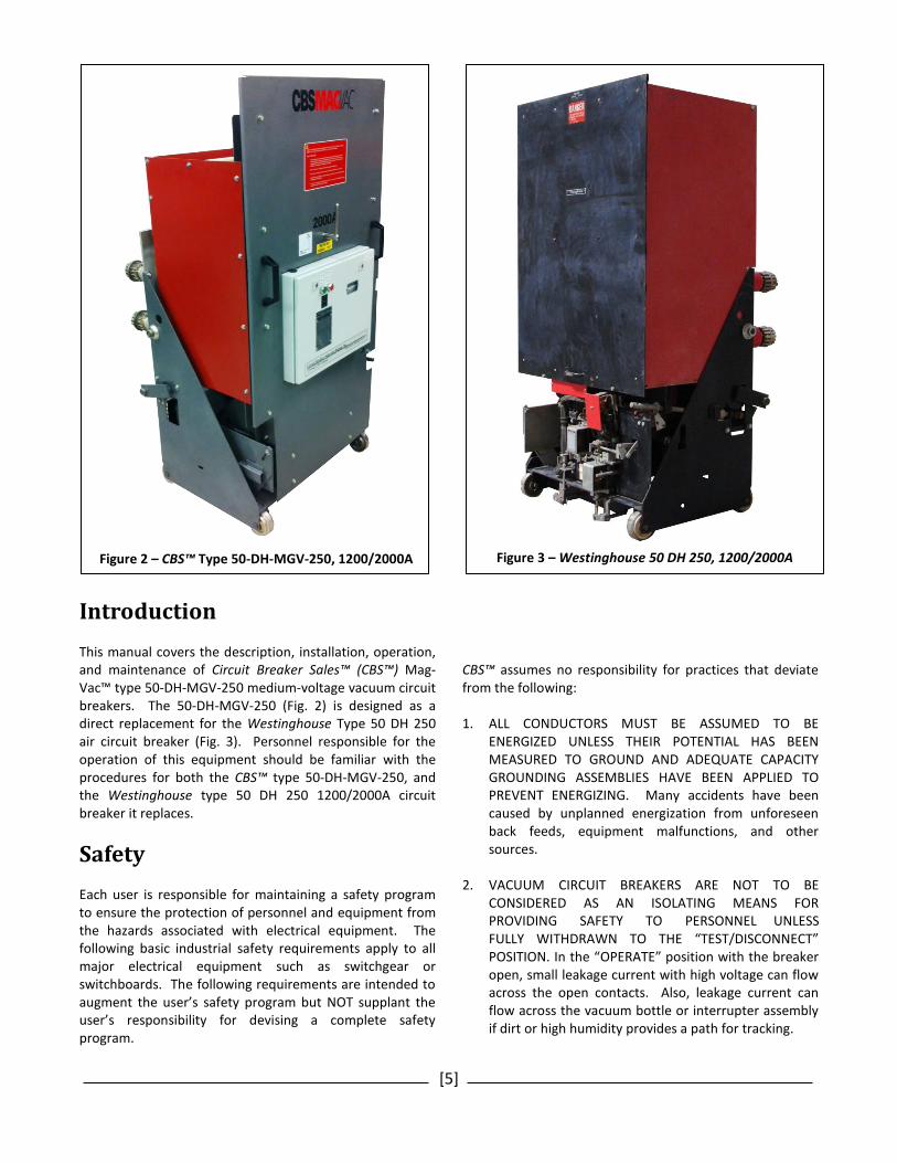
This manual covers the description, installation, operation, and maintenance of Circuit Breaker Sales™ (CBS™) Mag-Vac™ type 50-DH-MGV-250 medium-voltage vacuum circuit breakers. The 50-DH-MGV-250 (Fig. 2) is designed as a direct replacement for the Westinghouse Type 50 DH 250 air circuit breaker (Fig. 3). Personnel responsible for the operation of this equipment should be familiar with the procedures for both the CBS™ type 50-DH-MGV-250, and the Westinghouse type 50 DH 250 1200/2000A circuit breaker it replaces.
Safety
Each user is responsible for maintaining a safety program to ensure the protection of personnel and equipment from the hazards associated with electrical equipment. The following basic industrial safety requirements apply to all major electrical equipment such as switchgear or switchboards. The following requirements are intended to augment the user’s safety program but NOT supplant the user’s responsibility for devising a complete safety program.
CBS™ assumes no responsibility for practices that deviate from the following:
1. ALL CONDUCTORS MUST BE ASSUMED TO BE
ENERGIZED UNLESS THEIR POTENTIAL HAS BEEN MEASURED TO GROUND AND ADEQUATE CAPACITY GROUNDING ASSEMBLIES HAVE BEEN APPLIED TO PREVENT ENERGIZING. Many accidents have been caused by unplanned energization from unforeseen back feeds, equipment malfunctions, and other sources.
2. VACUUM CIRCUIT BREAKERS ARE NOT TO BE CONSIDERED AS AN ISOLATING MEANS FOR PROVIDING SAFETY TO PERSONNEL UNLESS FULLY WITHDRAWN TO THE “TEST/DISCONNECT” POSITION. In the “OPERATE” position with the breaker open, small leakage current with high voltage can flow across the open contacts. Also, leakage current can flow across the vacuum bottle or interrupter assembly if dirt or high humidity provides a path for tracking.
Figure 2 – CBS™ Type 50-DH-MGV-250, 1200/2000A Figure 3 – Westinghouse 50 DH 250, 1200/2000A

[6]
3. It is strongly recommended that all equipment be completely de-energized, verified to be “dead,” and then grounded with adequate capacity grounding assemblies prior to performing any maintenance or troubleshooting. The grounding cable assemblies must be able to withstand energizing fault levels so that protective equipment may clear the circuit safely. See Chapter 20 of ANSI/NFPA 70B, Electrical Equipment Maintenance, for further information.
Specific hazards throughout this instruction manual are presented in red danger call-outs, such as the following example:
DANGER
RED DANGER boxes contain information that point out potential hazards to personnel and equipment.
While personnel should pay particular attention to the hazards presented in red danger call-outs, it would be impossible to alert the operator to every potential hazard. It is the responsibility of knowledgeable operators to rely on safe work practices to protect them from the inherent risks associated with industrial electrical equipment. Important information throughout this instruction manual is emphasized with green attention call-outs, such as the following example.
ATTENTION
GREEN ATTENTION boxes contain useful information to which the reader will want to pay particular attention.
Circuit Breaker Sales™ MAG Vac™ circuit breakers are equipped with high-energy/high-speed magnetic mechanisms. The design includes several interlocks and safety features which help to ensure safe and proper operating sequences. To ensure the safety of personnel associated with the installation, operation, and maintenance of these circuit breakers, the following recommendations MUST be followed:
DANGER
Always ensure the circuit breaker displays OPEN/OFF prior to insertion into or removal from the connected position.
DANGER
Only qualified persons who are familiar with the installation and maintenance of medium-voltage circuit breakers should be permitted to work on these circuit breakers.
DANGER
Read these instructions carefully before attempting any installation, operation, or maintenance of these breakers.
DANGER
DO NOT work on an energized circuit breaker.
DANGER
DO NOT work on a circuit breaker unless all components are disconnected by means of a visual break and secure ground.
DANGER
DO NOT work on a circuit breaker while power is applied to the control power receptacle.
DANGER
DO NOT DEFEAT SAFETY INTERLOCKS. Defeating interlocks may result in property damage, bodily injury, and/or death.
DANGER
DO NOT work on a closed circuit breaker; doing so may result in bodily injury.
DANGER
DO NOT use a circuit breaker as the sole means of isolation of a high-voltage circuit.
DANGER
DO NOT install or remove circuit breakers without adequate personal protective equipment and/or a specifically designed remote racking device (contact CBS™ for remote racking solutions).

[7]
Section 1 – Receiving, Handling, and Storage
1.1 Receiving and Handling
Every circuit breaker is carefully tested and inspected then packaged securely to ensure the breaker arrives safely. Immediately upon receipt, the circuit breaker should be examined to ascertain if any damage was sustained during transit. If damage or evidence of rough handling is present, or the “Tip ‘n’ Tell” indicator is missing or disturbed, file a damage claim immediately with the Transportation Company and contact the CBS MAGVac™ sales office. Remove all traces of packing, crating, and foreign material carefully. Exercise care while uncrating the circuit breaker so that no damage will occur from careless or rough handling or from exposure to moisture or dirt. Save the shipping material for storing the circuit breaker when not in use. Verify the order with the packing list to ensure that no components have been overlooked or misplaced, such as racking and charging tools, test reports, and instruction booklets. The circuit breaker is normally shipped in the CLOSED position to prevent damage from occurring to the vacuum interrupter during shipment. Verify the indicator flags (Fig. 13, Fig. 19-6) on the front of the circuit breaker display OPEN prior to moving, installing, or removing. When lifting the circuit breaker, use of a specifically designed rigging or skid tray is recommended. If it is necessary to lift the circuit breaker without the designed rigging or skid, slings may be placed under the breaker frame, or hooks may be connected to the two lift locations are provided on the right and left sides of the circuit breaker housing (Fig. 4). When liftng, ensure a properly rated lifting apparatus is used, lift and lower the circuit breaker slowly, and avoid abrupt movements.
1.2 Storage
After inspection it is recommended that the circuit breaker be put into service in its permanent location immediately. If the circuit breaker cannot be placed into service ensure the following storage criteria are met: 1. Store the breaker unpacked and OPEN. 2. The breaker should be carefully protected against
condensation, preferably by storing it in a warm, dry room of moderate temperature such as 5–37⁰C (41–98⁰F). An environment high in humidity may have an adverse effect on the circuit breaker insulation and should be avoided.
3. The breaker should be stored in a clean location, free from corrosive gases or fumes; particular care should be taken to protect the equipment from moisture and cement/mineral dust, as this combination has a very corrosive effect on many breaker components.
4. Cover the circuit breaker with a plastic sheet to protect from dust, dirt, and small animal or insect infestation.
5. Outdoor storage is not recommended. When no other option is available, the breaker must be completely covered and protected from rain, snow, dirt and all other contaminants.
If the breaker is stored for any length of time, it should be inspected periodically to ensure that rust is not present and that the breaker is in good mechanical condition. Should the breaker be stored under unfavorable atmospheric conditions, it should be cleaned and dried out prior to being placed into service. If the breaker is stored longer than one year, prior to putting into service follow this procedure to ensure correct operation of the control module: · Connect auxiliary power supply to Control Module (CM) for 20 seconds. · Disconnect auxiliary power supply to CM for one minute. · Repeat this procedure two times. · Connect auxiliary power to CM for at least 8 hours.
DANGER
DO NOT improperly lift the breaker via the primary disconnects.

[8]
Figure 4 – Circuit Breaker Lift Points

[9]
Section 2 – Description and Operation
2.1 Introduction
The Circuit Breaker Sales™ Type 50-DH-MGV-250 vacuum circuit breaker is designed as a direct replacement for the Westinghouse Type 50 DH 250 air circuit breaker. This section provides basic descriptions of the circuit breaker components and its operation. A thorough understanding of 50-DH-MGV-250 circuit breaker hardware must be reached prior to installation, operation, and maintenance of the equipment.
DANGER
The circuit breakers described in this manual are designed and tested to operate within their nameplate ratings. OPERATION OUTSIDE OF THE RATINGS MAY CAUSE EQUIPMENT TO FAIL, RESULTING IN PROPERTY DAMAGE, BODILY INJURY, AND/OR DEATH.
13
1
7
Figure 5 – Circuit Breaker and Frame Components
1. Primary Disconnect Assembly 7. Magnetic Operating Mechanism 13. Racking Shaft 2. Secondary Disconnect 8. Position Interlock Switch/Manual Trip 14. Secondary Actuation 3. Levering-in Device Arm 9. Trip/Close push buttons 15. Shutter Roller 4. Blast Shield 10. Movable Frame (Truck) 16. Interlock Linkage Assembly 5. Ratings Nameplate 11. Flanged Steel Wheels (x4) 6. Control Module Enclosure 12. Primary Disconnects (x6)
2
3
4
5
8
6
9
14
5
10
12
15
11
163

[10]
2.2 Description
The 50-DH-MGV-250 circuit breaker is comprised of a movable frame (truck) (Fig. 5-10), on which are mounted the magnetic operating mechanism (Fig. 5-7), the disconnect assembly (Fig. 5-1), the manual trip latch, (Fig. 5-8) and the interlock linkage assembly (Fig 5-16, 5-8).
ATTENTION
All descriptions of circuit breaker operations and component locations assume the operator/reader is viewing the circuit breaker from the front unless otherwise stated.
2.2.1 Movable Frame
(Fig. 5-10, Fig. 6) – The movable frame is constructed of heavy-gauge steel and is the main support structure of the circuit breaker. The frame consists of the shutter rollers(Fig. 5-15, 6-1), the circuit breaker position interlock assembly (Fig. 6-2), the frame ground disconnect (Fig. 6-3), the racking levers (Fig. 6-4), steel wheels (Fig. 5-11), the blast shield (Fig. 5-4), the levering/racking assembly (Fig. 6-5), and the secondary disconnect assembly (Fig. 5-14). The circuit breaker ratings nameplate (Fig. 5-5) is mounted to the control module door.
DANGER
Use the handles provided on the blast shield to move the circuit breaker. NEVER handle or transport the circuit breaker via the primary disconnects.
Shutter Rollers (Fig. 5-15, 6-1) – The shutter rollers are fixtures on the sides of the rolling breaker frame. As the breaker is racked into the cubicle, the rollers actuate the movable shutters located in the rear of the cubicle. This allows a clear path for the primary disconnect fingers to engage the line/load current studs in the cubicle. Circuit Breaker Position Interlock (Fig. 6-2) – The circuit breaker position interlock is comprised of a steel lever that engages a mechanism that blocks the breaker from being racked /levered into the cubicle. This lever also manually opens the breaker contacts.
DANGER
Reconfiguring the circuit breaker position interlock can lead to installing the breaker when in the closed position. The interlock is configured at the factory. Never tamper with the circuit breaker interlock.
Frame Ground Disconnect (Fig. 6-3) – All metal parts of the circuit breaker except those that are part of the high-voltage or control circuitry, are grounded through a high-current sliding contact. The frame ground disconnect grounds the frame when the breaker is installed in the TEST/DISCONNECT or OPERATE position in the breaker compartment.
Figure 6 – Frame Components, Rear 1. Shutter Rollers 2. Interlock Assembly 3. Frame Ground Disconnect 4. Racking Levers 5. Levering / Racking Assembly
1
2
3
Circuit Breaker Ratings Nameplate
55
3
4

[11]
Racking Levers (Fig. 6-4) – The racking levers are located on each side of the breaker frame and are connected by a common shaft. On each arm is a roller which engages a groove in the sidewall of the cell. They are actuated when the breaker is levered into the cell. In their original position they point to the rear and slightly downward. The arms rotate 193 degrees, slowly moving the breaker body into the cell. Flanged Steel Wheels (Fig. 5-11) – The four non-pivoting steel wheels provide a means of positioning the circuit breaker in the switchgear and for removing the breaker from the cubicle for circuit isolation and maintenance. Blast Shield (Fig. 5-4) – The blast shield is constructed from heavy-gauge steel and serves as a grounded barrier between the operator and the high-voltage present in the switchgear. Control Module Enclosure (Fig. 5-6) – The circuit breaker’s control module enclosure protects the operator from the control voltage and contains the close and trip buttons. The circuit breaker ratings nameplate (Fig. 5-5) is mounted to the control module enclosure’s front panel.
2.2.2 ISM / Magnetic Operating Mechanism
(Fig. 5-7, Fig. 7, Fig. 12) – The 50-DH-MGV-250 utilizes a self-contained breaker element with a magnetic actuator driven mechanism. This highly innovative indoor switching module (ISM, Fig. 7) is designed specifically for high switching duty cycles, where traditional spring charged mechanisms would require significant maintenance. Each pole is enclosed in a molded support insulator (Fig. 7-1) with fixing point inserts (Fig. 7-16). The vacuum interrupters in each pole (Fig. 7-3) are connected to drive insulators (Fig. 7-6), which in turn are connected to magnetic actuators (Fig. 7-7) inside the base of the module. The three magnetic actuators (one per pole) are linked together via a synchronizing shaft (Fig. 7-11). When driven by a pulse from the control module (Fig. 16) through the actuator coils (Fig. 7-9), the armatures of the actuators (Fig. 7-10) rise and become magnetically latched to the stators (Fig. 7-7), closing the primary contacts. This in turn rotates the synchronizing shaft, engaging six normally open (NO) and six normally closed (NC) auxiliary contacts (Fig. 7-12)
A reverse pulse from the control module disrupts the magnetic latching, allowing an opening spring (Fig. 7-8) in each actuator to open the contacts at high speed.
DANGER
The ISM is a sealed unit. There are no user-serviceable parts inside the ISM; any attempt to repair, modify or otherwise adjust the ISM could result in severe injury or death when re-connected to primary power.

[12]
During the close / open operations, a position indicator link (Fig. 7-14) drives a semaphore (Section 2.2.5) to give visible indication of the breaker status. An interlocking shaft (Fig. 7-13) provides manual trip and simultaneous electrical / mechanical blocking of racking operations. In the 50-DH-MGV-250 this shaft is connected directly to the interlocking mechanisms of the truck.
The ISM breaker element is built with compact 4th generation vacuum interrupters (Fig. 8). These interrupters use a welded steel disc bellows (Fig. 9) to both reduce the size and dramatically increase the lifetime of the interrupters.
The mechanism consists of the following components: the operating mechanism (Fig. 10) the support insulator (Fig. 7-1), contact terminals (Fig. 7-2, 5), vacuum interrupter assemblies (Fig 7-3, 4), actuator assemblies (Fig. 7-6, 7,9), opening and contact pressure springs (Fig. 7-8), the synchronizing shaft (Fig. 7-11), auxiliary contacts (Fig. 7-12), and the interlock shaft (Fig 7-13). The circuit breaker operating mechanism can also be equipped with an optional mechanism operated contacts (MOC) operating linkage assembly. All electrical controls are housed in the control module (Fig. 5-6, Fig. 16). A detailed explanation of the magnetic operating mechanism is described in Section 2.3. Support Insulator (Fig. 7-1, 16) – The vacuum interrupter assemblies, insulated pull-rods, and contact terminals are all housed in structurally supportive insulator housings. These support insulators also contain the fixing points used to mount the element onto the circuit breaker frame. Contact Terminals (Fig. 7-2, 5) – The interrupting contact surfaces inside the vacuum interrupters are connected to the primary disconnects via upper and lower terminals, rather than connecting the disconnect bus bars directly to the vacuum interrupters. This relieves any possibility of introducing unnecessary stress on the vacuum interrupter, and also allows the movable contact of the interrupter to be isolated from the disconnect bus. Vacuum Interrupters (Fig. 7-3, 4, Fig. 8, Fig. 9, Fig. 10) – In the MagVac switching module, the vacuum interrupters are sealed inside of insulating jackets. They are capable of 30,000 close-open operations at full load without any maintenance. Actuator Assemblies (Fig. 7-6, 7, 9, 10) – The contacts inside the MagVac switching module are opened and closed using an electromagnetic actuator coil that is powered by a stator and interfaces with a magnetic armature. This actuation drives the opening and closing of the circuit breaker’s contacts. The actuator is held in two end positions without the use of mechanical latches. In the OPEN position the armature is held by the opening

[13]
spring. In the CLOSED position the armature is held by magnetic flux produced by a ring permanent magnet. Opening and Contact Pressure Springs (Fig. 7-8) – The MagVac breaker uses a contact pressure spring to ensure that the movable contact closes securely against the fixed contact. In addition to the contact pressure spring, an opening spring assists in the opening and closing of the electrical contacts. The opening spring holds the breaker in its open position. Synchronizing Shaft (Fig. 7-11) – The movable contacts of all three phases of the MagVac switching module are linked together by a synchronizing shaft. This ensures that each phase will open and close in an identical fashion. Auxiliary Contacts (Fig. 7-12) – The breaker-mounted auxiliary micro switches provide auxiliary contacts for the control circuitry of the circuit breaker and contacts for use in relaying and external logic circuits. The auxiliary switch is actuated electrically, and by the synchronizing shaft. The auxiliary switch contains both normally open (A) and normally closed (B) contacts. To clarify, when the circuit breaker is closed, A contacts are closed, while B contacts are open. The position interlock switch (PIS) (Fig. 7-13) is actuated by the hand-operated interlock lever (Fig. 5-8) located in the center of the blast shield. The position interlock switch manually trips the breaker when operated by hand. The position interlock switch must be engaged before the breaker can be racked in. When the handle is turned 90 degrees, it actuates a linkage that removes a blockage which previously prevented the racking shaft from engaging the pinion gear of the racking levers, thus allowing the breaker to be racked/levered into the cell.
2.2.3 Disconnect Assembly
(Fig. 5-1,2,12) – The disconnect assembly is the primary current path of the circuit breaker. The disconnect assembly is comprised of the primary (Fig. 11-4) and secondary (Fig. 5-2, 11-6) disconnects, the vacuum interrupters (Fig. 7-3, Fig. 10), the insulating push-rods (Fig. 7-6), and the phase barriers (Fig. 7-1, Fig. 11-2).

[14]
Vacuum Interrupters (Fig. 7-3, Fig.10) – Each circuit breaker contains three vacuum interrupters (commonly known as vacuum bottles), one bottle per phase. The vacuum interrupters are essentially a movable and stationary contact enclosed within a vacuum chamber. The upper, stationary terminal of the vacuum interrupter is connected to the upper disconnect stud (Fig. 11-1) of the MagVac operating mechanism which in turn is connected through a copper bus-bar to the forward primary disconnect. The lower, movable interrupter terminal passes through a slide contact which transmits current to the lower disconnect stud (Fig. 11-3) and connects to the driving mechanism of the circuit breaker via an insulated push-rod; the lower disconnect stud is connected to the rear primary disconnect of the circuit breaker via a copper bus-bar. A metal bellows assembly provides a secure seal around the movable contact, preventing a loss of vacuum while permitting vertical motion of the movable contact.
Insulated Pull-rods (Fig. 7-6) – There are three insulated pull-rods. Each pull-rod connects the movable terminal of one of the vacuum interrupters to the actuator assembly of the MagVac operating mechanism. The pull-rods transfer the motion generated by the magnetic actuators to the movable terminals while insulating the high voltage potential present on the primary disconnect assembly from the circuit breaker frame and operating mechanism. Primary Disconnects (Fig. 5-12, 11-4) – The circuit breaker has three sets of primary disconnects, one set per phase. The three upper primaries are connected to the stationary terminals of the vacuum interrupters, the three lower primaries attach to the movable terminals. When the circuit breaker is in the OPERATE position, the female primary disconnects connect with stationary male disconnect studs in the cubicle. Secondary Disconnects (Fig. 5-2, 11-6) – The secondary disconnect provides an array of contacts for making electrical connections with the breaker electrical controls, limit switches, and breaker mounted auxiliary switch. The secondary disconnects mates with the secondary disconnect receptacle in the circuit breaker cubicle when the breaker is in the OPERATE position. Phase Barriers (Fig.7-1, Fig. 11-2) – Each vacuum interrupter assembly is insulated via its vacuum interrupter phase barrier. The phase barriers provide an insulating medium between each phase and the walls of the circuit breaker cubicle
2.2.4 Interlock Linkage Assembly
(Fig. 5-9, 10) – The interlock linkage assembly consists of the hand-operated interlock switch) position interlock, and their associated linkage. An explanation of the operation of the interlock linkage assembly is included in the Operations Section 2.2.8.
2.2.5 Semaphore Operation
The ISM breaker element utilizes a mechanical semaphore (contact position indicator) for primary contact indication. This semaphore is connected to the ISM breaker element via a tension cable (Fig. 12). On rotation of the interlocking shaft during close or open, the semaphore changes state to indicate “Open” (Fig. 13) or “Closed” (Fig. 14). The semaphore is visible

[15]
through the viewing window located at the bottom right hand side of the circuit breaker (Fig. 19-6).
2.2.6 Auxiliary Circuit Control Box
DANGER
The ACCB contains live points when connected to the auxiliary power supply that could cause severe injury or death. Disconnect all sources of power before opening the ACCB door.
The ACCB houses the CM-12-02A control module (Fig. 16-1). This module is purpose-designed to control the ISM breaker element. In addition to the control module, the ACCB houses terminal blocks for interconnecting the devices (Fig. 16-3), wiring duct to route the cabling (Fig. 16-2), and power resistors (Fig. 16-4) that form the trip / close supervisory circuit. The ACCB has a “coin-slot” cam lock that allows for easy access to the auxiliary circuits during configuration or servicing (Fig. 15).

[16]
2.2.7 Circuit Breaker Levering Device (Racking)
In order to move the breaker in or out of the metal cell against the resistance of the contact fingers on the rear of each bushing, a levering-in device is provided on each breaker. Figure 17 shows the levering mechanism used to rack-in the DH circuit breaker. The main parts of the device are: 1. The levering shaft (Racking shaft) 2. The interlocking fork 3. Levering shaft worm gear 4. Levering arm pinion gear 5. Levering Arms These are a part of the chassis (truck) assembly, and are identical to those on an original Westinghouse 50-DH-250 circuit breaker. The levering-in procedure is therefore
identical to that of the original Westinghouse circuit breaker. There is an arm on each side mounted on a common shaft across the back of the breaker. On each (levering) arm is a roller which engages a groove in the sidewall of the cell. A removable crank engages the racking shaft in the right front corner of the breaker which turns the arms through a worm gear and pinion arrangement. Before a breaker is rolled in to a cell, the arms with rollers, at each side of the breaker must point to the rear and slightly downward as shown in figure 17. The arms travel 193 degrees and assume a horizontal forward-facing
DANGER
DO NOT DEFEAT SAFETY INTERLOCKS. Defeating interlocks may result in property damage, bodily injury, and/or death.

[17]
position when the breaker is cranked into the operating position in the cell. To put the arms in the position shown in figure 17, place the original Westinghouse crank on the racking shaft at the front right corner of the breaker, push in, and rotate COUNTER-CLOCKWISE to engage the coupling in the levering-in mechanism. The breaker contacts must be open to engage the coupling. To ensure that the contacts are open, simply turn the large handle in the middle of the blast shield (Fig. 5-8) counterclockwise 90 degrees. Continue rotating the crank until the end of travel. During this time, as long as positive pressure is applied, the interlock mechanism will hold the coupling engaged. At the end of travel, the interlock will release, the crank will move to the front, and the breaker will be ready to install into the cell. With the levering-arms in the position show in figure 17, the breaker is now ready to be rolled into the cell as far as the test position. The rollers on the arms strike vertical angles on the cell wall and stop the breaker at the test position. If the breaker is to be operated at this position, remove the crank and engage the secondary contacts in the manner described in section 2.2.9 Secondary Contacts. To move the breaker from the test position to the fully engaged operating position, you must first ensure that the manual trip lever has been turned 90 degrees to the left. Then put the crank on the shaft, push in and rotate to engage the levering-in coupling and crank CLOCKWISE. The torque required will increase when the primary contact fingers engage the stationary contact studs in the cell. Continue cranking to the end of the travel where the interlock will again fall free, pushing the crank back out. Remove the crank, and return the manual trip/interlock handle on the blast shield back to its upright position. The breaker is now ready to operate electrically using the close and trip buttons. To remove the breaker from the operating position, first check that the breaker is open. The levering-in device cannot be engaged, unless the breaker is open, and the manual trip/position interlock handle is turned to the left. Put the crank on the racking shaft, push in and rotate to engage the coupling, and turn COUNTER-CLOCKWISE until
the breaker returns to the test position. Remove the crank. The breaker may now be operated at the test position or be rolled out of the cell.
2.2.8 Circuit Breaker Interlocks
The purpose of the circuit breaker interlocks is to prevent the installation or removal of the circuit breaker from the OPERATE position while the breaker contacts are CLOSED. Mechanical and electrical interlocks keep the breaker from closing unless the breaker is locked in either the TEST or OPERATE position. The interlock linkage assembly consists of the hand-lever interlock, position interlock, and their associated linkage. Levering Interlock - The levering interlock is designed to prevent moving the breaker into or out of the energized position if the breaker contacts are in the closed position. The primary function of this interlock is to provide a lock that prevents the racking shaft from being engaged when the breaker contacts are closed. The levering interlock is activated by turning the handle located on the blast shield 90 degrees COUNTER-CLOCKWISE. This rotates a linkage which interacts with the levering process. When the handle is turned to the left, it opens a gate, which allows the motion of a fork, which normally prohibits the racking/levering shaft from being pushed in. When this handle is turned to the left, the racking shaft is free to engage the worm gear seen in Fig. 17. When the interlock handle is in its upright position, it prohibits the motion of a linkage that interfaces with the levering shaft. This linkage contains a fork which either allows, or blocks the racking shaft from being pushed inward by the levering crank. The racking shaft must travel approximately 1-2 inches inward towards the cell to engage the breaker’s levering mechanism. This can be seen in Figure 17. The handle used to actuate the levering interlock serves multiple purposes. It is also the lever used to manually trip the breaker. This process is discussed in section 2.3.3.
Engaged

[18]
2.2.9 Secondary Contacts
The breaker control wiring is arranged for draw-out disconnection by means of an 18-point connector plug arranged to connect to a mating receptacle mounted in the rear of the cell. See Fig. 11-6. The secondary connector plug is mounted on a movable bracket on the lower left-hand side of the breaker frame. This permits it to be extended to the rear while the breaker is in the test position, and to make contact with the stationary receptacle so that the control circuits are completed. Sufficient clearance is provided in the mounting of both plug and receptacle, and two large tapered pins on the plug provide positive alignment. The secondary contacts of the plug are made from high-conductivity copper alloy and are slotted to provide a spring action which ensures a good electrical contact. The flexible control wires are soldered to each plug and are arranged in a loop to allow free movement of the contact slide. To engage the secondary contacts while the breaker is in the test position, place the breaker maintenance closing handle (Provided with original Westinghouse breaker. Contact CBS MagVac for replacement) in the socket on the secondary contact slide at the lower left hand side of the breaker. Push forward slightly to release the latch, then raise up slightly to the end of travel. To disengage the secondary contacts, the maintenance closing handle is inserted into the socket and lowered. See Figure 18 for
engaged/disengaged positions. If the breaker is levered into the operating position, the secondary plug and slide will automatically return to the normal position; and the latch will hold it in place when the breaker is later moved to the test position.

[19]
2.3 Operation
This section introduces and explains the modes of CBS Mag-Vac™ Type 50-DH-MGV-250 circuit breaker operation. The status conditions of the circuit breaker are the charging, closing, opening (tripping), trip-free, and rapid auto-reclosing modes of operation.
2.3.1 Closing Operation
In the open position the contacts are kept open by the force of the opening springs. To close the contacts the coils of the magnetic actuators are excited by a current impulse of the close capacitors of the CM. As a result the contacts close. At the same time the opening springs are compressed. In the close position the contacts are kept closed by means of the magnetic force only. The ISM maintains the closed position without mechanical latching so in case of a failure of the auxiliary power supply.
2.3.2 Open (Tripping Operation)
To open the contacts a current impulse in the reverse polarity derived from the opening capacitors of the CM is
injected in the coils of the magnetic actuators, releasing the magnetic holding force. The compressed opening springs and contact pressure springs open the contacts.
2.3.3 Manual-Emergency-Tripping
The ISM can be tripped mechanically without auxiliary power supply (emergency trip). It may be opened manually by means of the interlocking shaft rotating counter-clockwise. The interlocking cam of the interlocking shaft acts on an armature inside the MagVac mechanism when the manual trip lever (Fig. 19-1) is rotated 90 degrees to the left. As the air gap increases, the opening springs and contact pressure springs overcome any magnetic holding force and the module opens.
2.3.4 Controls and Indications
The controls and indications are located on the front of the circuit breaker housing; see Fig. 19 for locations and explanations of circuit breaker controls. The ISM breaker element is controlled and monitored by the CM-12-02A. This control module has the following functions: 1. Trip / close of the ISM breaker element 2. Monitoring of the magnetic actuator health 3. Monitoring of the actual breaker contact position vs. the CM command position 4. Trip / close supervisory circuit emulation 5. Ready / malfunction indication 6. Anti-pumping duty The CM-12-02A receives close or trip commands from the existing control system in the switchgear. On acceptance of a close command, the CM will send a ~300VDC pulse to the magnetic actuators of the ISM. This causes the permanent magnetic latching of the actuators, until a trip command is received. On acceptance of a trip command, the CM will send a much lower level pulse to the actuators, weakening the magnetic latch and allowing the pull down springs to open the contacts. This entire operating sequence can be seen in the timing chart (Fig. 21). The CM-12-02A has status indication provided through three LED’s (Fig. 20). The LED’s are visible through the control module viewing window (Fig. 5-6).

[20]
When the breaker is first inserted into the test position in the cubicle (or attached to a dedicated testing device), the “POWER” LED will begin blinking. At this stage the CM is charging its internal capacitors in preparation for acceptance of a close command. After approximately 10 seconds, the “READY” LED will remain continuously lit. At this stage the CM is ready to accept a “CLOSE” command. The capacitors are ready for a “TRIP” command within 100ms of power-on. On receipt of a “CLOSE” command from the switchgear or locally through the circuit breaker push button, the CM will close the ISM. The “READY“ light will remain illuminated. Throughout and after this stage the CM is ready for a “TRIP” command. There are three special conditions in which a command will not be executed: 1. Anti-Pumping Duty - During close operation, if a trip instruction is received before the close instruction
becomes passive then the close instruction will be blocked. For the next close operation the close instruction must be reapplied after the trip instruction has become passive. 2. Blocking Duty - For close and trip inputs the following rule is applicable: If a close instruction is received while a trip instruction remains active then the close instruction is blocked. For the next close operation the close instruction must be reapplied after the trip instruction has become passive.

[21]
4. Combined Blocking and Anti-Pumping Duty - A close
command during a pending trip command is not executed (blocking duty) even if it is pending longer than the trip command (anti-pumping duty).

[22]
Section 3 – Commissioning and Installation
3.1 General
Prior to installation of the circuit breaker into a switchboard, certain preliminary inspections are made to ensure proper operation.
3.2 Installation Inspection
Inspect the condition of contact and electrical connections prior to installing the circuit breaker into the switchboard. Even though each circuit breaker is completely adjusted and tested at the factory, shipping and handling conditions could cause defects.
3.3 Compartment Positions
The four positions of the circuit breaker with respect to the cubicle are: REMOVED: The circuit breaker is either partially or completely out of the cubicle. DISCONNECTED: The circuit breaker is installed in the cubicle with the interlock lever engaged in the disconnect position and the front panel aligned with the position indicator. TEST: The circuit breaker interlock lever is engaged in the test position; the front panel will align with the TEST position indicator. OPERATE: The circuit breaker is engaged in the operate position; the front panel will align with the CONNECTED position indicator.
3.4 Examination and Preoperational Checks
Prior to placing the circuit breaker into the compartment, and especially when it is the first time the circuit breaker is installed, perform the following: 1. Check that the data on the circuit breaker rating
nameplate agrees with that stated on the purchase order and with the installation requirements. Ensure that the CBS Mag-Vac™ type 50-DH-MGV-250 circuit breaker nameplate data matches the Westinghouse Type 50 DH 250 circuit breaker it is replacing.
2. Check the circuit breaker for general cleanliness and ensure that it is free of foreign material.
3. The circuit breaker is normally shipped in the CLOSED position to prevent damage from occurring to the vacuum interrupter during shipment. Verify the indicator flag on the front of the circuit breaker display OPEN prior to moving, installing, or removing.
4. If the circuit breaker is being commissioned, perform a vacuum interrupter integrity test as described in Section 4. (This test is performed at the factory prior to shipment.)
5. Install the Circuit Breaker into the TEST position inside the cell.
6. Charge the capacitors: Closing and trip capacitors of the CM are charged when the CM is connected to the auxiliary power supply. The charged closing capacitors correspond with the charged springs of a conventional circuit breaker. After the loss of auxiliary power supply any pending trip or any trip command arriving to the CM will be executed up to 30 seconds after loss.
7. Close the circuit breaker by pressing the red Close (I) pushbutton.
8. Open the circuit breaker by pressing the green Open (O) pushbutton.
DANGER
When the circuit breaker operating housing is accessed for maintenance, ensure the housing is free of tools and foreign material prior to replacing the housing faceplate.
9. Record the circuit breaker operation counter (Fig.
19-2) 10. Continue to Section 3.5.
3.5 Installing Breaker into Compartment
The installation procedure for the CBS™ Mag-Vac™ type 50-DH-MGV-250 is identical to the Westinghouse type 50 DH 250 circuit breaker it replaces. Operator should refer to this manual and the original Westinghouse instruction manual for details on the racking/levering system of this breaker. NOTE: CLOCKWISE ROTATION of racking crank for inserting breaker. COUNTERCLOCKWISE ROTATION of racking crank for removal of the breaker.

[23]
To place the breaker in the OPERATE position, proceed as given below:
ATTENTION
All circuit breaker removable elements of the same type and rating which have duplicate wiring may be interchanged.
DANGER
CBS recommends utilizing a remote racking system to protect against potential arc-flash hazards.
1. Prior to placing the circuit breaker in the cubicle,
ensure the circuit breaker is OPEN. 2. Verify control power is off and remove foreign
material that might hinder or prevent smooth insertion of the breaker.
3. If primary contact engagement will be verified (see step 10) de-energize and lockout primary system power.
4. Line up the circuit breaker in front of the respective cubicle.
DANGER
NEVER rely on circuit breaker interlocks to OPEN the circuit breaker prior to installing/removing from the OPERATE or TEST positions.
5. Apply a .03 to .06 inch (1 to 2mm) layer of Sanchem
NO-OX-ID Special Grade “A” contact lubricant (or equivalent) inside the primary finger clusters at contact point area.
ATTENTION
The finger clusters are lubricated in preparation for the check of the primary contact engagement which is made when the circuit breaker is removed (see step 10) and also to protect contact surfaces (see step 11).
6. Turn the hand-lever interlock located on the blast
shield to the left and move the breaker into the disconnect position, the flanged steel wheels of truck should align with the guide rails on the cell floor. In this position, check the following items: a) The secondary contacts have good alignment. b) The ground contact (underside, rear of breaker)
has good contact alignment.
c) If an MOC switch is provided, that the operating fork on the breaker is in line with the MOC operating arm.
d) The breaker shutter system is in line and will engage correctly.
7. Slide the breaker completely into the test position. To close the breaker, make sure that the hand-operated manual trip lever is in its upright position. In this position, check the following items:
a) That the secondary contacts can be slid
backwards and make adequate contact with the receiving socket in the rear of the cell.
b) That the ground contact has been made, or is in alignment.
c) If the cubicle has an MOC switch installed with TEST position pickup, verify that it has properly engaged the breaker operating fork.
d) Close and trip the breaker electrically several times using the panel-mounted control switch.
e) De-energize control power. f) Close the breaker and trip mechanically by
turning the manual trip handle on the front of the blast door. The circuit breaker is now discharged and ready for insertion to the connected position.
DANGER
Always ensure the circuit breaker displays OPEN/OFF and DISCHARGED prior to insertion to or removal from the connected position.
8. Grasp the circuit breaker by the handles and push
into compartment until stopped. 9. Turn the hand-operated interlock on the blast shield
to the left and lever the breaker into the operating position. Use the original Westinghouse racking crank. The breaker will travel towards the rear of the cell until the primary disconnects are completely latched to the contacts in the back of the cell. Once the primary disconnect fingers (Fig. 11-5) begin to connect to the cell’s contacts, turning the racking/levering crank may become slightly more difficult. This is normal. Once any extra pressure is experienced, there will only be 1-2 inches of travel left in the levering procedure. NOTE: For details on the racking/levering assembly, refer to section 2.3.4.

[24]
10. Ensure that the breaker is completely racked in and the crank will not turn any further. Do not continue to turn the levering crank if the breaker is completely racked in, because you can damage the levering shaft pin. Check the indicator on the cell or cubicle to make sure that the breaker is in the fully CONNECTED position.
11. Energize control power by engaging the secondary disconnects. Perform the following checks in this position: a) With primary system power de-energized, close
and trip the breaker to verify operation in the connected position.
b) Check ground contact.
DANGER
IT WILL BE NECESSARY TO OPEN THE SHUTTERS COVERING THE PRIMARY DISCONNECTS. MAKE CERTAIN THAT BOTH LINE/LOAD AND BUS ARE DE-ENERGIZED FIRST. DO NOT MAKE THIS CHECK FOR BUS TIE UNITS, SOURCE BREAKERS, OR UNITS THAT COULD BE BACK-FED UNLESS ALL BUSSES ARE DE-ENERGIZED. FAILURE TO DO THIS CAN RESULT IN SERIOUS INJURY, BURNS, OR DEATH. THEN OPEN THE SHUTTERS AND BLOCK THEM OPEN. USING A HOT STICK POTENTIAL DEVICE, DOUBLE-CHECK THAT ALL DISCONNECTS ARE DE-ENERGIZED.
12. Remove the breaker from the cubicle to check the
length of engagement of the primary contact fingers over the straight portion of the contact surface on the stationary contact. The contact point of the fingers must have a minimum engagement of .12 inch (3mm) over the straight portion of the stationary contacts (Fig. 25). Proper connection can be observed by opening the shutters and with a flashlight note the polish marks on the stationary contacts. Remove excess grease from contact fingers.
13. Before final installation of the circuit breaker, check
that all primary disconnect studs, contact fingers, and secondary disconnect strips and fingers are lubricated with a film of Sanchem™ NO-OX-ID Special grade “A” contact lubricant. This lubricant will insure long service life for the contacts and will protect them against corrosion and overheating.
Section 4 – Trouble Shooting
4.1 Introduction
The self-monitoring system inside the CM detects
malfunctions and reports them via the MALFUNCTION
LED using blink signals. The meaning of the blink codes
and the variations per type of malfunction are shown in
the following table.
As the CM monitors the majority of the functionality of
the breaker, any troubleshooting should start with
review of the trouble codes in Table 1.

[25]
4.2 CM Trouble Codes

[26]
DANGER
The 50-DHP-MGV-250 has few parts that can be serviced by the end user. Information in this troubleshooting section is for reference only, and should be used when contacting CBS MAGVac™ to isolate the malfunction.

[27]
Section 5 – Maintenance
5.1 Maintenance Schedule
DANGER
Tests and maintenance routines described in this document should only be carried out by qualified and experienced breaker maintenance personnel. Certain procedures, such as dielectric withstand tests, can produce hazardous voltages as well as x-ray emissions.
Additionally:
1.NEVER work on a breaker in the connected position 2.NEVER work on a breaker with the secondary disconnects engaged 3.NEVER defeat safety interlocks 4.ALWAYS keep at least two meters away from breakers under dielectric test 5.ALWAYS follow safe discharge procedures after applying a dielectric test to a circuit breaker
Periodic maintenance and checks should be performed on the breaker to ensure safe and continued service. A maintenance schedule should be developed that takes into consideration the conditions of the site, including particulate accumulation, frequency of switching and routine switchgear maintenance. In a clean environment, the MAGVac breaker should not require more than periodic cleaning and inspection. Table 2 can serve as a guide to establish the best protocol of tests and frequency for your site.
Inspection and cleaning are part of the routine maintenance of the circuit breaker and can be performed by qualified site personnel. Contact, dielectric, and timing tests require specialized equipment and knowledge, and
should only be performed by qualified breaker service personnel. Any maintenance of the breaker should be undertaken only by qualified breaker service personnel.

[28]
5.2 Inspection and Cleaning
The breaker should be inspected routinely. This includes anytime the breaker is fully withdrawn from the cell, or during regular maintenance intervals. The inspection is primarily visual: - Check primary contacts for signs of damage, such as broken contact fingers, burn marks or pitting. - Check secondary self-coupling contacts for signs of damage, such as burn marks or pitting. - Check mechanical connections for loose or missing bolts, binding of parts, deformation or physical damage. - Check racking mechanism for smooth operation without binding or noise indicative of a lack of lubrication. - Open auxiliary cabinet on the breaker and inspect for loose wires, evidence of burn marks on electrical connections or evidence of heat damage. - Check insulation for cracks and damage. The breaker should be cleaned with a lint free, dry cloth to remove dust or other particulates that may interfere with operation of the breaker. Any items that do not pass inspection should be logged and rectified prior to putting the circuit breaker back into service.
5.3 Contact Resistance Test
Contact wear of the circuit breaker follows a logarithmic scale as shown in Fig. 26. At full load, the ISM element is capable of 30,000 operations without maintenance. At higher current interruption, up to and including the rated value of 31.5 kA, the number of operations drops accordingly. It is recommended to test the contact resistance of each phase of the breaker after five fault events. As some older relays are not capable of duplicating the curve in Fig. 26 for calculation and logging, any fault event should be taken as a full fault on the scale. A 100 amp DLRO is recommended to obtain the most accurate contact resistance measurement. If the breaker has contact resistance which exceeds the specified limit of <40 uOhms, but is less than twice this limit (<80 uOhms), continuation of use is possible, if actual continuous current does not exceed the following value:
Ia<Ir*√(Rr/Ra)
Where: la, Ra – Actual current and contact resistance respectively lr, Rr – Rated values If the contact resistance is more than double the specified limit, the ISM must be replaced.
5.4 Dielectric Withstand – Primary
Dielectric tests of the primary paths of the circuit breaker are critical to the safe operation of the device. These tests should take place any time a primary component is altered (replaced or repaired) or every three years. There are three primary tests: Vacuum integrity, phase to phase insulation, and phase to ground insulation.
DANGER
Dielectric tests of the primary path of the circuit breaker involve high voltages, and under vertain circumstances can cause X-ray emmissions from the vacuum interrupters. This test should only be performed by qualified personnel with the appropriate safety equipment.
The test voltage levels listed in this document should not be exceeded during testing in order to mitigate the X-ray potential.

[29]
Vacuum Integrity:
This test measures the relative level of vacuum present in the interrupters by applying a high voltage source across the all three poles, with the contacts open.
1. Tie the lower three phases to frame ground and to the dielectric tester ground. 2. Tie the upper poles together and connect to the dielectric tester lead. 3. Ensure personnel are at least six feet from the breaker under test and any high voltage connections. 4. Apply 15 kV AC, or 20kV DC, depending on the type of test equipment used. 5. If the test shows any more than 200 µA, the ISM element should be considered failed and taken out of service. Note that vacuum interrupters can show restrikes when DC current is applied. If any reading is suspect, the breaker should be taken out of service until CBS MagVac can be notified for further investigation.
Phase to Phase:
This test measures the relative level of isolation between the poles by applying a high voltage source to the center pole, with the contacts closed and the two outer poles tied together to ground.
1. Tie the two outer poles to frame ground and to the dielectric tester ground 2. Tie the center pole to the dielectric tester lead. 3. Ensure personnel are at least six feet from the breaker under test and any high voltage connections. 4. Apply 15kV AC or 20kV DC, depending on the type of test equipment used. 5. If the test shows any more than 200 µA, the breaker should be taken out of service until further analysis and repair has taken place.
Phase to Ground:
This test measures the relative level of isolation between the poles and ground by trying all of the poles to the voltage source, with the contacts closed.

[30]
1. Tie the ground lead of the dielectric tester to the frame ground of the circuit breaker. 2. Tie the upper and lower poles together and to the dielectric tester lead. Do not connect to ground. 3. Ensure personnel are at least six feet away from the breaker under test and any high voltage connections. 4. Apply 15kV AC or 20kV DC, depending on the type of test equipment used. 5. If the test shows any more than 200 µA, the ISM element should be considered failed and taken out of service.
5.5 Timing Test
Timing tests validate the contact opening and closing speed, and are an assurance that the circuit breaker is operating within specifications for fault clearing speed. This test requires specialized, calibrated equipment and should be left to qualified service technicians. It should be performed after replacement of the control module or ISM breaker element or every three years. From initiation of command, the total close time should be <77 ms (<5cycles), while trip time should be <42 ms (<2.8 cycles). Should the breaker be higher than these values, CBS MAGVac should be contacted for further determination of the remedial action required.
5.6 Lubrication of Moving Parts
During routine maintenance, the breaker should be checked for adequate lubrication of the moving parts shown in Fig. 34 through 43.
Should lubrication be required, clean the lubrication points first with dry rags to remove dirt buildup and other contaminants. Re-apply the correct lubricant for each point, taking care to follow the instructions of the lubricant manufacturer.
DANGER
The current carrying components on the breaker can only be lubricated with NO-OX-ID Special Grade “A” manufactured by Sanchem. Use of any other lubricant for these areas could cause overheating and / or electrical malfunction.

[31]

[32]

[33]
In Figure 33 – Figure 41, the contact pairs and components that need to be greased with ANDEROL 757 (Tenneco Chemical) are marked with the letter “A.”
In Figure 33 – Figure 41, the contact pairs and single contact surfaces that need to be greased with NO-OX-ID Special “Grade A” (Sanchem), are marked with the letter “N.”

[34]

[35]

[36]

[37]

[38]

[39]
Section 6 - Mechanical Drawings

[40]

[41]

[42]

[43]